Three-dimensional Numerical Simulation of a Mechanized Twin Tunnels in Soft Ground
12
Three-dimensional numerical simulation of a mechanized twin tunnels in soft ground Ngoc-Anh Do a,d , Daniel Dias b,⇑ , Pierpaolo Oreste c , Irini Djeran-Maigre a a University of Lyon, INSA of Lyon, Laboratory LGCIE, Villeurbanne, France b Grenoble Alpes University, Laboratory LTHE, Grenoble, France c Politecnico of Torino, Department of Environmental, Land and Infrastructural Engineering, Italy d Hanoi University of Mining and Geology, Department of Underground and Mining Construction, Faculty of Civil Engineering, Hanoi, Viet Nam article info Article history: Received 8 April 2013 Received in revised form 15 January 2014 Accepted 2 February 2014 Available online 25 February 2014 Keywords: Numerical modelling Twin tunnel Segmental lining Lining response Settlement abstract The increase in transportation in large cities makes it necessary to construct of twin tunnels at shallow depths. Thus, the prediction of the influence of a new tunnel construction on an already existing one plays a key role in the optimal design and construction of close parallel shield tunnels in order to avoid any damage to the existing tunnel during and after excavation of the new tunnel. Most of the reported cases in the literature on parallel mechanized excavation of twin tunnels have focused on the effects of the ground condition, tunnel size, tunnel depth, surface loads, and relative posi- tion between the two tunnels on tunnel behaviour. The numerical investigation performed in this study, using the FLAC 3D finite difference element programme, has made it possible to include the influence of the construction process between the two tunnels. The structural forces induced in both tunnels and the development of the displacement field in the surrounding ground have been highlighted. The results of the numerical analysis have indicated a great impact of a new tunnel construction on an existing tunnel. The influence of the lagged distance between the two tunnels faces has also been high- lighted. Generally, the simultaneous excavation of twin tunnels causes smaller structural forces and lin- ing displacements than those induced in the case of twin tunnels excavated at a large lagged distance. However, the simultaneous excavation of twin tunnels could result in a higher settlement above the two tunnels. Ó 2014 Elsevier Ltd. All rights reserved. 1. Introduction In recent years, many tunnels have been built in urban environ- ments; this often involves the construction of twin tunnels in close proximity to each other. In addition, in many cases, the new tunnel is often excavated adjacent to an already existing one. Thus, the prediction of the influence of new shield tunnel construction on the existing tunnel plays a key role in the optimal design and construction of close parallel shield tunnels in order to avoid any damage to the existing tunnel during and after excavation of the new tunnel. Interactions between closely-spaced tunnels were studied in the past using a variety of approaches: physical model testing, field observations, empirical/analytical methods and finite element modelling. Kim et al. (1996, 1998) performed physical tests to investigate the response of the first tunnel lining on the approaching of the second shield. The results of their model tests showed that the interaction effects are greater in the spring line and crown of the existing tunnel. Chapman et al. (2007) described results from a series of small-scale (1/50) laboratory model tests carried out in a kaolin clay which focused on studying the short-term ground movements associated with closely spaced multiple tunnels. The influence of tunnel distance, tunnel depth and tunnel number were highlighted. The results showed asymmetrical settlement troughs, greater settlement above the second of the twin tunnels con- structed. Their study also demonstrated that the commonly used semi-empirical method to predict the short-term settlement above twin tunnels, using the summation of Gaussian curves, can give inaccurate results. In the study by Choi and Lee (2010), the influ- ence of the size of an existing tunnel, the distance between tunnel centres and the lateral earth pressure factor on mechanical behav- iour of the existing and new tunnels was investigated by quantify- ing the displacement and crack propagation during the excavation http://dx.doi.org/10.1016/j.tust.2014.02.001 0886-7798/Ó 2014 Elsevier Ltd. All rights reserved. ⇑ Corresponding author. Tel.: +33 4 76 63 51 35; fax: +33 4 76 82 52 86. E-mail address: [email protected] (D. Dias). Tunnelling and Underground Space Technology 42 (2014) 40–51 Contents lists available at ScienceDirect Tunnelling and Underground Space Technology journal homepage: www.elsevier.com/locate/tust
-
Upload
carmine-tranfa -
Category
Documents
-
view
8 -
download
0
description
Tunneling, FEM, soft ground
Transcript of Three-dimensional Numerical Simulation of a Mechanized Twin Tunnels in Soft Ground
Tunnelling and Underground Space Technology 42 (2014) 40–51
Contents lists available at ScienceDirect
Tunnelling and Underground Space Technology
journal homepage: www.elsevier .com/ locate / tust
Three-dimensional numerical simulation of a mechanized twin tunnelsin soft ground
http://dx.doi.org/10.1016/j.tust.2014.02.0010886-7798/� 2014 Elsevier Ltd. All rights reserved.
⇑ Corresponding author. Tel.: +33 4 76 63 51 35; fax: +33 4 76 82 52 86.E-mail address: [email protected] (D. Dias).
Ngoc-Anh Do a,d, Daniel Dias b,⇑, Pierpaolo Oreste c, Irini Djeran-Maigre a
a University of Lyon, INSA of Lyon, Laboratory LGCIE, Villeurbanne, Franceb Grenoble Alpes University, Laboratory LTHE, Grenoble, Francec Politecnico of Torino, Department of Environmental, Land and Infrastructural Engineering, Italyd Hanoi University of Mining and Geology, Department of Underground and Mining Construction, Faculty of Civil Engineering, Hanoi, Viet Nam
a r t i c l e i n f o a b s t r a c t
Article history:Received 8 April 2013Received in revised form 15 January 2014Accepted 2 February 2014Available online 25 February 2014
Keywords:Numerical modellingTwin tunnelSegmental liningLining responseSettlement
The increase in transportation in large cities makes it necessary to construct of twin tunnels at shallowdepths. Thus, the prediction of the influence of a new tunnel construction on an already existing one playsa key role in the optimal design and construction of close parallel shield tunnels in order to avoid anydamage to the existing tunnel during and after excavation of the new tunnel.
Most of the reported cases in the literature on parallel mechanized excavation of twin tunnels havefocused on the effects of the ground condition, tunnel size, tunnel depth, surface loads, and relative posi-tion between the two tunnels on tunnel behaviour. The numerical investigation performed in this study,using the FLAC3D finite difference element programme, has made it possible to include the influence ofthe construction process between the two tunnels. The structural forces induced in both tunnels andthe development of the displacement field in the surrounding ground have been highlighted.
The results of the numerical analysis have indicated a great impact of a new tunnel construction on anexisting tunnel. The influence of the lagged distance between the two tunnels faces has also been high-lighted. Generally, the simultaneous excavation of twin tunnels causes smaller structural forces and lin-ing displacements than those induced in the case of twin tunnels excavated at a large lagged distance.However, the simultaneous excavation of twin tunnels could result in a higher settlement above thetwo tunnels.
� 2014 Elsevier Ltd. All rights reserved.
1. Introduction
In recent years, many tunnels have been built in urban environ-ments; this often involves the construction of twin tunnels in closeproximity to each other. In addition, in many cases, the new tunnelis often excavated adjacent to an already existing one. Thus, theprediction of the influence of new shield tunnel construction onthe existing tunnel plays a key role in the optimal design andconstruction of close parallel shield tunnels in order to avoid anydamage to the existing tunnel during and after excavation of thenew tunnel.
Interactions between closely-spaced tunnels were studied inthe past using a variety of approaches: physical model testing, fieldobservations, empirical/analytical methods and finite elementmodelling.
Kim et al. (1996, 1998) performed physical tests to investigatethe response of the first tunnel lining on the approaching of thesecond shield. The results of their model tests showed thatthe interaction effects are greater in the spring line and crown ofthe existing tunnel. Chapman et al. (2007) described results froma series of small-scale (1/50) laboratory model tests carried outin a kaolin clay which focused on studying the short-term groundmovements associated with closely spaced multiple tunnels. Theinfluence of tunnel distance, tunnel depth and tunnel number werehighlighted. The results showed asymmetrical settlement troughs,greater settlement above the second of the twin tunnels con-structed. Their study also demonstrated that the commonly usedsemi-empirical method to predict the short-term settlement abovetwin tunnels, using the summation of Gaussian curves, can giveinaccurate results. In the study by Choi and Lee (2010), the influ-ence of the size of an existing tunnel, the distance between tunnelcentres and the lateral earth pressure factor on mechanical behav-iour of the existing and new tunnels was investigated by quantify-ing the displacement and crack propagation during the excavation
N.-A. Do et al. / Tunnelling and Underground Space Technology 42 (2014) 40–51 41
of a new tunnel constructed near an existing tunnel. A series ofexperimental model tests was performed and analysed. It wasfound that the displacements decreased and stabilized as the dis-tance between the tunnel centres increased, depending on the sizeof the existing tunnel.
Suwansawat and Einstein (2007) introduced interesting fieldmeasurement results on ground movements induced by parallelEPB tunnels excavated in soft ground in Bangkok. They showedthat the operational parameters, such as face pressure, penetrationrate, grouting pressure and filling, have significant effects on themaximum settlement and extent of the settlement trough. Theyalso showed that the maximum settlement for twin tunnels isnot usually located over the midpoint between the two tunnelsand that the settlement trough is often asymmetric.
Chen et al. (2011) presented field measurements conducted onparallel tunnels using EPB shields in silty soil. Their results showeda great dependence of the ground movements on the distance be-tween the second tunnel face and the monitored section. They alsoindicated that the two settlement troughs caused by the construc-tion of the first and the second tunnel had similar shapes. However,the second tunnel trough was shallower and wider than that of thefirst tunnel. The first tunnel made the symmetric axis of the finaltrough of the parallel tunnels incline towards the first tunnel. Inthe study by Ocak (2012), thirty longitudinal monitoring sections,obtained through EPB tunnelling, were used to determine theinteractions of the longitudinal surface settlement profiles in shal-low twin tunnels. He et al. (2012) carried out field and model tests,based on Chengdu Metro Line 1 in China, to study the surface set-tlement caused by twin parallel shield tunnelling in sandy cobblestrata. The surface settlement mechanism and the effect of tunneldistance on the surface settlement were also studied using the dis-crete element method (DEM). They showed that when the spacingbetween two tunnels is higher than twice the tunnel diameter, anindependent collapsed arch can form. However, in any of the abovestudies, the resulting structural forces induced in the tunnel liningwere not mentioned.
Field observations remain the key to understanding the interac-tion between adjacent tunnels. Unfortunately, however, field dataare often incomplete. It is clear that model testing can only be usedto study limited interaction behaviour. Empirical and analyticalmethods, using the superposition technique (e.g. Wang et al.,2003; Hunt, 2005; Suwansawat and Einstein, 2007; Yang andWang, 2011), have been used on the basis of the prediction of eachindividual excavation in order to obtain the final accumulated set-tlement trough. Generally, superposition method cannot take intoaccount rigorously the effect of an existing tunnel and the repeatedunloading of the ground caused by the previous excavation of thefirst tunnel and, therefore, the settlement curves do not representthe final displacement very well (Divall et al., 2012). Furthermore,empirical and analytical methods also introduce drawbacks forthose cases in which complex geological conditions (e.g. multilayerstrata) are expected. The use of a finite element model seems to be apromising way of addressing this issue.
Leca (1989), Addenbrooke and Potts (1996), Yamaguchi et al.(1998), Sagaseta et al. (1999), Hefny et al. (2004), Ng et al.(2004), Karakus et al. (2007), Hage Chehade and Shahrour (2008),Afifipour et al. (2011), Chakeri et al. (2011), Ercelebi et al. (2011),Mirhabibi and Soroush (2012), Hasanpour et al. (2012) have all car-ried out numerical analysis of this interaction problem. Most ofthese studies focused on considering the effect of the ground con-dition, tunnel size, tunnel depth, surface loads, and relative posi-tion between two tunnels on the surface settlement. Their resultswere similar in that the influence of the second tunnel on the pre-viously installed lining of the first one has been shown to dependon the relative position of the tunnel and on the spacing betweenthe two tunnels.
The literature reviewed above clearly indicates that an exten-sive amount of research has been conducted on tunnel interactionsbetween parallel tunnels. Most of this research has focused on theinfluence of twin tunnels on ground deformation. However, lesswork has been devoted to the influence of the interaction betweentunnels on the structural forces induced in a tunnel lining.
Ng et al. (2004) performed a series of three dimensional (3D)numerical simulations to investigate the interactions betweentwo parallel noncircular tunnels constructed using the newAustrian tunnelling method (NATM). Special attention was paidto the influence of the lagged distance between the excavated facesof the twin tunnels (LF) and the load-transfer mechanism betweenthe two tunnels. It was found that LF has a greater influence on thehorizontal movement than on the vertical movement of eachtunnel and that the magnitude of the maximum settlement is inde-pendent of LF. They showed that the distributions of the bendingmoment induced in the tunnel lining are similar in shape, butdifferent in magnitude in the two tunnels.
In the study by Liu et al. (2008), the effect of tunnelling on theexisting support system (i.e. shotcrete lining and rock bolts) of anadjacent tunnel was investigated through full 3D finite elementcalculations, coupled with an elasto-plastic material model. Itwas concluded that the driving of a new tunnel significantly af-fects the existing support system when the advancing tunnel facepasses the existing support system and has less effect when theface is far from the system. It was also pointed out that the effectsof tunnelling on the existing support system depend to a greatextent on the relative position between the existing and newtunnels.
In order to investigate the influence of new shield tunnel exca-vation on the internal forces and deformations in the lining of anexisting tunnel, Li et al. (2010) presented a series of 3D numericalsimulations of the interaction between two parallel shield tunnelsand parametric analyses. Unfortunately, the existence of thejoints in the segmental lining, the construction loads inducedduring shield tunnelling, such as face pressure, jacking force,grouting pressure, were not simulated in this numerical model.The impact of the new tunnel excavation on the existing tunnelduring the advancement of the new tunnel was not consideredeither.
The purpose of a numerical mechanized tunnelling (TBM)model is to take into consideration the large number of processesthat take place during tunnel excavation. In order to conduct arigorous analysis, a 3D numerical model should be used. Obviously,there is not a full 3D numerical simulation for mechanized twintunnels in soft ground that allows both ground displacement andstructural lining forces to be taken into consideration.
The main purpose of this study was to provide a full 3D modelwhich would allow the behaviour of the interaction of mechanizedtwin tunnels to be evaluated, in terms of structural forces inducedin the tunnel lining and ground displacement surrounding the twotunnels. Most of the main elements of a mechanized excavationcan be simulated in this model: the conical geometry of the shield,the face pressure, the circumferential pressure acting on the cylin-drical surface of the excavated ground in the working chamber be-hind the tunnel face, the circumferential pressure caused by themigration of the grout acting on the excavated ground at the shieldtail, the grouting pressure acting simultaneously on the excavatedground and on the tunnel structure behind the shield tail, progres-sive hardening of the grout, the jacking force, the weight of theshield machine, the weight of the back-up train behind the shieldmachine and the lining joint pattern, including the segment joints,the ring joints and their connection condition. The CYsoil model,which is a strain hardening constitutive model, has been adopted.The Bologna–Florence high speed railway line has been adopted inthis study as a reference case.
900
Tunnel periphery
Shield’s self-weight
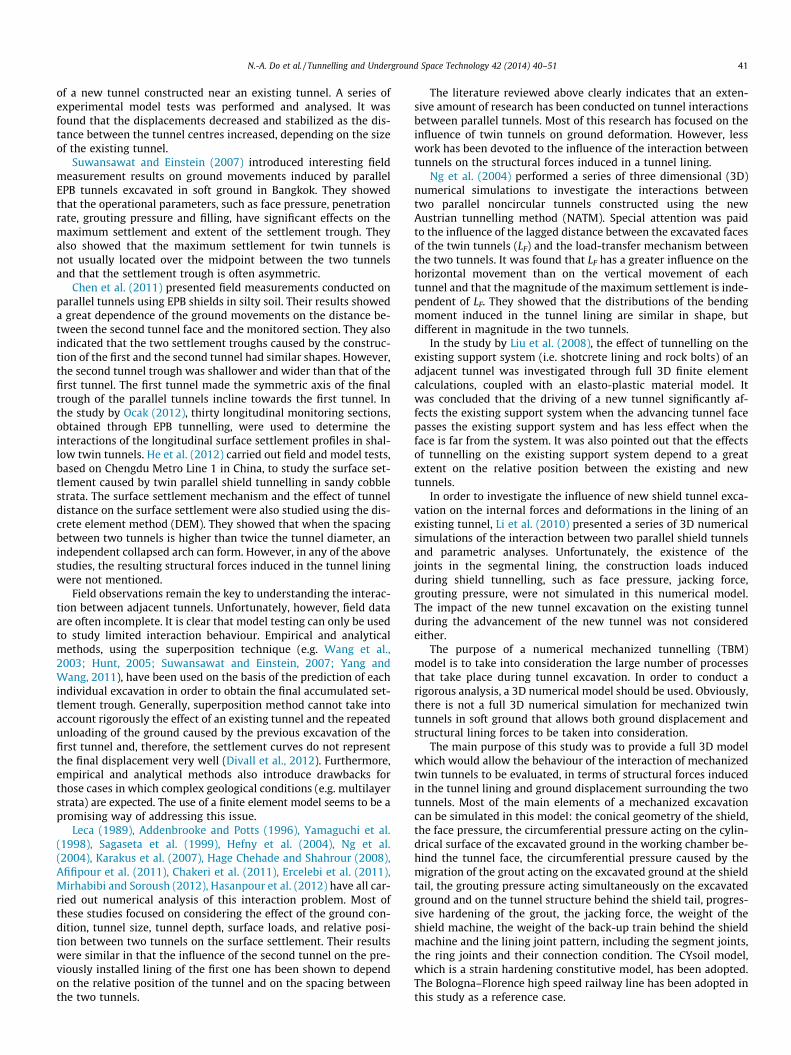
Fig. 2. Self-weight scheme of the shield machine.
42 N.-A. Do et al. / Tunnelling and Underground Space Technology 42 (2014) 40–51
2. Numerical model
2.1. Three-dimensional numerical model
The numerical model, the 3D simulation procedure of a singletunnel and the parameter calibration of the CY soil model weredescribed in Do et al. (2013a). Therefore, only a short overview isgiven here. However, the numerical model introduced by Doet al. (2013a) has been improved and some other components ofthe tunnelling process have been simulated in the present study.It includes the weight of the shield machine and the weight ofthe back-up train behind the shield machine.
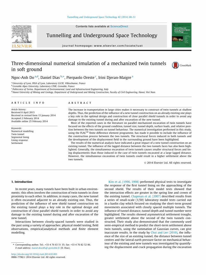
The tunnel construction process is modelled using a step-by-step approach. Each excavation step corresponds to an advance-ment of the tunnel face of 1.5 m, which is equal to the width of alining ring. A schematic view of the present model is provided inFig. 1.
Face pressure has been estimated depending on the horizontalstress induced in the ground in front of the tunnel face (Mollonet al., 2013). This face pressure has been modelled by applying apressure distribution to the excavation face using a trapezoidalprofile in order to account for the slurry density. Owing a slightovercutting, a possible slurry migration could occur over a shortdistance behind the cutting wheel. Therefore, in addition to thepressure acting on the tunnel face, a pressure, caused by the slurrysolution, has also been applied to the cylindrical surface just be-hind the tunnel face. The shield machine has been simulated using‘‘fictive’’ shield introduced by Mollon et al. (2013), Dias et al.(2000) and Jenck and Dias (2004). The geometrical parameters ofthe shield are presented in Fig. 1.
The self-weight of the shield is simulated through the verticalloads acting on the grid points of the ground mesh at the tunnelbottom region over an assumed range of 90� in the cross-sectionand over the whole shield length, as can be seen in Figs. 1 and 2.In this study, a shield weight value of 6000 kN, which refers to atunnel diameter of 9.4 m (JSCE, 1996), has been adopted.
The distribution of the jacking force has been assumed to be lin-ear over the height of the tunnel. The jacking forces were set oneach segment, considering three plates located at 1/6, 1/2, and 5/6of the segment length. A total jacking force of about 40 MN wasadopted in the present model on the basis of the theoreticalmethod proposed by Rijke (2006).
The grouting action is modelled in two phases: (1) the liquidstate (state 1) represented by a certain pressure acting on the
Face
pre
ssur
e
Shield
Cutting wheel
Grouting press
Jacking force
1.5m 1.5m 7.5m 1.5m
1.5cm
Shield weight
Fig. 1. Layout of the proposed
ground surface and on the tunnel lining; (2) the solid state (state 2).The distributional radial pressure has been used to simulate thiskind of pressure. The grouting pressure has been estimateddepending on the ground overburden pressure at the crown ofeach tunnel (Mollon et al., 2013). The grout was simulated byadopting a uniform pressure which was applied to both the cylin-drical surface of the excavated ground and the external surface ofthe tunnel lining. As for the face pressure, the annular void be-tween the outside surface of the shield and the excavated groundmade the migration of some grout towards the shield possible. Thismigration was simulated by means of a triangular pressure overthe length of one ring (1.5 m). The grout was assumed to hardenbeyond this length and was simulated by means of volume ele-ments with perfect elastic behaviour, and with the elastic charac-teristics Egrout = 10 MPa and mgrout = 0.22 (Mollon et al., 2013).
In the present model, the tunnel segments have been modelledusing a linear-elastic embedded liner element. The segment jointshave been simulated using double node connections. The stiffnesscharacteristics of the joint connection have been represented by aset composed of a rotational spring (Kh), an axial spring (KA) and aradial spring (KR) (Do et al., 2013a, 2013b).
In the same way as for the segment joint, the ring joint has alsobeen simulated using double connections. In this study, the rigiditycharacteristics of the ring joint connection have been representedby a set composed of a rotational spring (KhR), an axial spring(KAR) and a radial spring (KRR). The interaction mechanism of eachspring is the same as that applied for a segment joint.
Once the TBM back-up train enters the excavated tunnels dur-ing the excavation process, it is necessary to take its self-weightinto consideration. In a study performed by Lambrughi et al.
Segmental lining
Fresh grout Hardened grout ure
1.5m
2.5cm
12.5cm
9.1mBack-up train weight
TBM model (not scaled).
Measured ring (30)First tunnel (left)
Second tunnel (right)
Tunnel face
YMS
Tunnelling direction
y
x
Shield
Segmental lining B
LF
LS
LS
Shield
Fig. 3. Plan view of the twin tunnels (not scaled).
N.-A. Do et al. / Tunnelling and Underground Space Technology 42 (2014) 40–51 43
(2012), this weight was simulated by artificially increasing thedensity value of the concrete lining. Kasper and Meschke (2004,2006) instead modelled the back-up train using an assumed load-ing scheme along the tunnel axis. In the present study, a totalweight of 3980 kN for the back-up train has been simulatedthrough the distribution loads which act on the lining elementsat the tunnel bottom region over an assumed angle of 90� in thecross-section and over a tunnel length of 72 m behind the shieldtail (Kasper and Meschke, 2004) (see Fig. 1).
2.2. Simulation procedure of mechanized twin tunnels
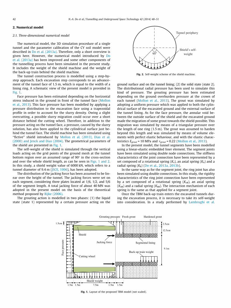
The twin tunnel excavation sequence was modelled as follows:(i) excavation of the first tunnel (left); (ii) excavation of the secondtunnel (right) with a lagged distance LF behind the face of the firsttunnel. The plan view and typical cross section of the twin tunnelexcavation procedure is illustrated in Figs. 3 and 4.
In this work, two different lagged distances (i.e., LF = 0D and10D) that correspond to LF = 0 and 7.875LS, in which LS is the shield
H
D
tl
x
DB
Tunnel on the left
Tunnel on the right
PC
B/2
z
Fig. 4. Typical cross section view of the twin tunnels with the lateral movementmonitoring axis PC located in the middle between the two tubes (not scaled).
Fig. 5. Perspective view of the developed nu
length (LS = 12 m in the present model), between the tunnel on theleft and the one on the right have been adopted and analysed. Thecase of LF = 0D corresponds to the situation in which two tunnelfaces are excavated simultaneously in parallel. The case ofLF = 10D means that the second (new) tunnel is excavated whenthe lining structure behaviour and ground displacement causedby the first (existing) tunnel excavation appear to have reached asteady state. The latter case usually occurs in reality. The twin tun-nels in the Bologna–Florence railway line project presented in thispaper is a typical example. In fact, the distance between the twotunnels in the Bologna–Florence railway line project is 15 m(Croce, 2011). However, in order to highlight the influence of theexcavation process of a new tunnel on an existing tunnel, a dis-tance from centre to centre of 11.75 m (1.25D) has been adoptedin this study.
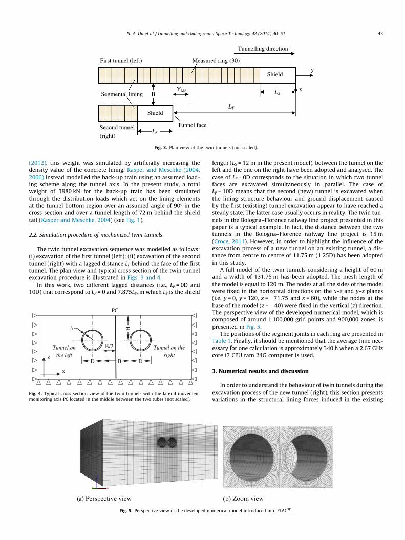
A full model of the twin tunnels considering a height of 60 mand a width of 131.75 m has been adopted. The mesh length ofthe model is equal to 120 m. The nodes at all the sides of the modelwere fixed in the horizontal directions on the x–z and y–z planes(i.e. y = 0, y = 120, x = �71.75 and x = 60), while the nodes at thebase of the model (z = �40) were fixed in the vertical (z) direction.The perspective view of the developed numerical model, which iscomposed of around 1,100,000 grid points and 900,000 zones, ispresented in Fig. 5.
The positions of the segment joints in each ring are presented inTable 1. Finally, it should be mentioned that the average time nec-essary for one calculation is approximately 340 h when a 2.67 GHzcore i7 CPU ram 24G computer is used.
3. Numerical results and discussion
In order to understand the behaviour of twin tunnels during theexcavation process of the new tunnel (right), this section presentsvariations in the structural lining forces induced in the existing
merical model introduced into FLAC3D.
Ring 1
Ring 2
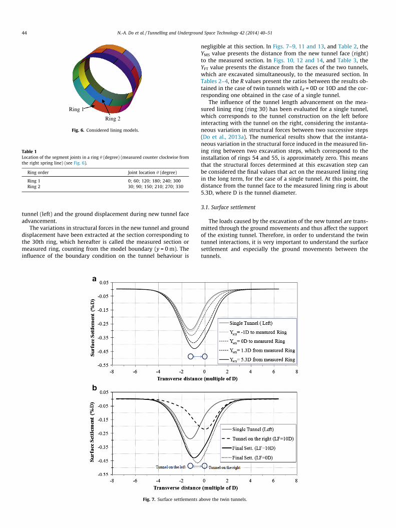
Fig. 6. Considered lining models.
Table 1Location of the segment joints in a ring h (degree) (measured counter clockwise fromthe right spring line) (see Fig. 6).
Ring order Joint location h (degree)
Ring 1 0; 60; 120; 180; 240; 300Ring 2 30; 90; 150; 210; 270; 330
44 N.-A. Do et al. / Tunnelling and Underground Space Technology 42 (2014) 40–51
tunnel (left) and the ground displacement during new tunnel faceadvancement.
The variations in structural forces in the new tunnel and grounddisplacement have been extracted at the section corresponding tothe 30th ring, which hereafter is called the measured section ormeasured ring, counting from the model boundary (y = 0 m). Theinfluence of the boundary condition on the tunnel behaviour is
Fig. 7. Surface settlements a
negligible at this section. In Figs. 7–9, 11 and 13, and Table 2, theYMS value presents the distance from the new tunnel face (right)to the measured section. In Figs. 10, 12 and 14, and Table 3, theYFT value presents the distance from the faces of the two tunnels,which are excavated simultaneously, to the measured section. InTables 2–4, the R values present the ratios between the results ob-tained in the case of twin tunnels with LF = 0D or 10D and the cor-responding one obtained in the case of a single tunnel.
The influence of the tunnel length advancement on the mea-sured lining ring (ring 30) has been evaluated for a single tunnel,which corresponds to the tunnel construction on the left beforeinteracting with the tunnel on the right, considering the instanta-neous variation in structural forces between two successive steps(Do et al., 2013a). The numerical results show that the instanta-neous variation in the structural force induced in the measured lin-ing ring between two excavation steps, which correspond to theinstallation of rings 54 and 55, is approximately zero. This meansthat the structural forces determined at this excavation step canbe considered the final values that act on the measured lining ringin the long term, for the case of a single tunnel. At this point, thedistance from the tunnel face to the measured lining ring is about5.3D, where D is the tunnel diameter.
3.1. Surface settlement
The loads caused by the excavation of the new tunnel are trans-mitted through the ground movements and thus affect the supportof the existing tunnel. Therefore, in order to understand the twintunnel interactions, it is very important to understand the surfacesettlement and especially the ground movements between thetunnels.
bove the twin tunnels.

Fig. 8. Horizontal displacements between the twin tunnels, for the LF = 10D case.
Fig. 10. Normal displacement in measured lining ring 30 of the tunnel on the left,for the LF = 0D case.
N.-A. Do et al. / Tunnelling and Underground Space Technology 42 (2014) 40–51 45
Fig. 7a shows the development of the surface settlement troughin the transverse section during the face advancement of the newtunnel on the right in the case of LF = 10D. This figure shows thatthe twin tunnels cause an increase in the surface settlement. Thiscould be explained by the accumulated loss of the ground in bothtwo tunnels. In the considered case, the maximum settlement
Fig. 9. Normal displacement in measured lining ring 30 of the existing (left) tunnel,for the LF = 10D case.
measured above the twin tunnels is 47.4% higher than that devel-oped above a single tunnel. In addition, the settlement profile isasymmetric. This means that the maximum settlement is notlocated over the mid-point between the two tunnels. During thenew tunnel advancement (right), the settlement trough shiftsgradually from the left to the right. An asymmetric profile of thesettlement trough has also been observed through field measure-ments obtained at shield tunnelling sites (Suwansawat andEinstein, 2007; Chen et al., 2011), analytical results using thesuperposition technique (Suwansawat and Einstein, 2007) andlaboratory model tests (Chapman et al., 2006; 2007).
Fig. 7b shows that the two settlement troughs caused by theconstruction of the tunnels on the left and right have a similarshape. The settlement trough above the new tunnel (right) is deter-mined on the basic of the final settlement trough of the twin tun-nels minus the one developed above the existing tunnel (left)before it interacts with the new tunnel. However, the settlementtrough caused by the excavation of the new tunnel is shallowerand wider than the one caused by the existing tunnel. These con-clusions are in good agreement with field observations made byChen et al. (2011), and He et al. (2012) during the excavation oftwin tunnels through respectively silty and sandy soil. The volumeloss ratios, determined at the final state as the ratio of settlementtrough area developed on the ground surface to the cross-sectionarea of the tunnel, of the existing tunnel and new tunnel are sim-ilar and equal to about 0.92% and 0.79%, respectively, and the totalvolume loss above the twin tunnels is equal to 1.71%. Above resultare however different from the laboratory results obtained fromthe work of Chapman et al. (2007) conducted in clay. Their workshowed a greater settlement above the second tunnel. This differ-ence could be attributed to the influence of the soil type or due tothe undrained behaviour of soils.
Fig. 7b also presents a comparison of the final settlementtroughs for the different construction procedures (LF = 0D and10D). The maximum settlement above the twin tunnels of about43.8 mm (0.47%D) (Table 4) and the volume loss ratio of 1.81%are observed in the LF = 0D case. These results are 109% and 106%higher than the corresponding ones for the LF = 10D case. However,the widths of the settlement troughs are similar in both cases. In
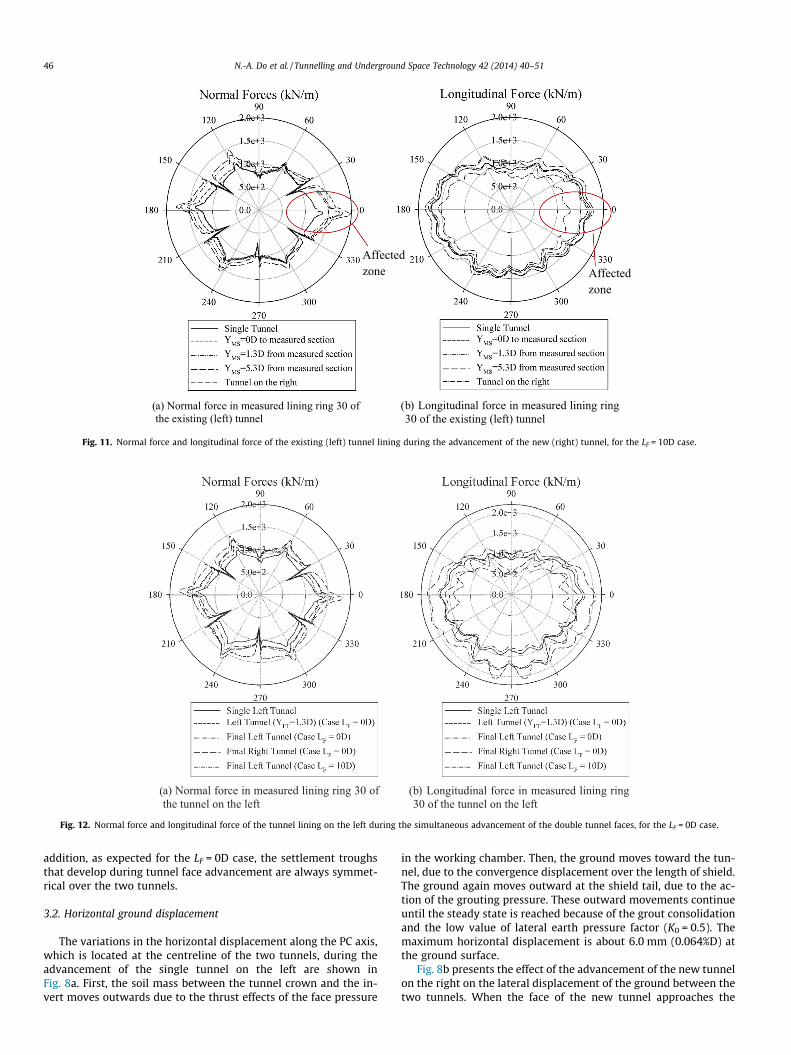
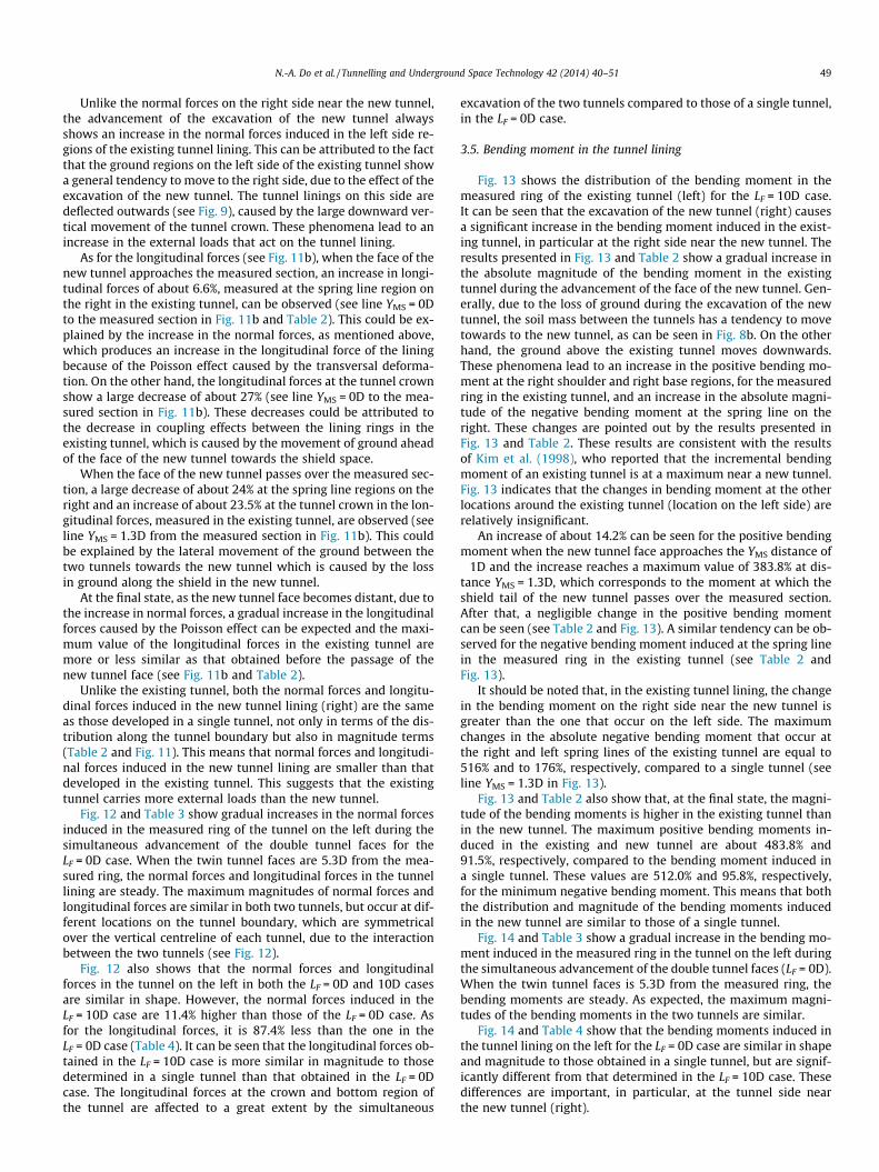
Fig. 11. Normal force and longitudinal force of the existing (left) tunnel lining during the advancement of the new (right) tunnel, for the LF = 10D case.
Fig. 12. Normal force and longitudinal force of the tunnel lining on the left during the simultaneous advancement of the double tunnel faces, for the LF = 0D case.
46 N.-A. Do et al. / Tunnelling and Underground Space Technology 42 (2014) 40–51
addition, as expected for the LF = 0D case, the settlement troughsthat develop during tunnel face advancement are always symmet-rical over the two tunnels.
3.2. Horizontal ground displacement
The variations in the horizontal displacement along the PC axis,which is located at the centreline of the two tunnels, during theadvancement of the single tunnel on the left are shown inFig. 8a. First, the soil mass between the tunnel crown and the in-vert moves outwards due to the thrust effects of the face pressure
in the working chamber. Then, the ground moves toward the tun-nel, due to the convergence displacement over the length of shield.The ground again moves outward at the shield tail, due to the ac-tion of the grouting pressure. These outward movements continueuntil the steady state is reached because of the grout consolidationand the low value of lateral earth pressure factor (K0 = 0.5). Themaximum horizontal displacement is about 6.0 mm (0.064%D) atthe ground surface.
Fig. 8b presents the effect of the advancement of the new tunnelon the right on the lateral displacement of the ground between thetwo tunnels. When the face of the new tunnel approaches the

Fig. 13. Bending moment in measured lining ring 30 of the existing (left) tunnel, forthe LF = 10D case.
Table 2Development of the structural forces and deformation in measured ring 30 of the existing tunnel (left) and surface settlement during the new tunnel advancement (right) (for theLF = 10D case).
Parameters Single tunnel Distance YMS (m) Tunnel on the right
– �1D 0 1.3D 3D 4.5D 5.3D –
Max. pos. bending moment (kN m/m) 71.9 82.2 162.8 348.1 343.9 347.2 348.1 65.8RM+ (%) 100.0 114.2 226.2 483.8 478.0 482.5 483.8 91.5Min. neg. bending moment (kN m/m) �93.8 �107.4 �279.5 �498.1 �481.6 �481.2 �480.6 �89.9RM� (%) 100.0 114.5 297.8 530.7 513.1 512.8 512.0 95.8Max. normal force (kN/m) 1490 1598 2096 1859 1948 1931 1927 1491RN (%) 100.0 107.2 140.7 124.8 130.8 129.6 129.3 100.1Max. longitudinal force (kN/m) 1745 1966 1861 1719 1736 1809 1798 1667RLN (%) 100.0 112.7 106.6 98.5 99.5 103.6 103.0 95.5Max. normal displacement (mm) 5.69 6.72 9.28 13.18 14.33 15.09 15.42 5.24Rdisp+ (%) 100.0 118.2 163.1 231.8 252.0 265.3 271.2 92.1Min. normal displacement (mm) �2.78 �3.40 �5.80 �9.86 �9.00 �8.70 �8.65 �2.51Rdisp� (%) 100.0 122.2 208.6 354.5 323.8 312.9 310.8 90.1Max. settlement (mm) �27.4 �28.6 �31.3 �36.4 �39.0 �39.9 �40.3 –Rset (%) 100.0 104.4 114.5 133.0 142.6 145.9 147.4 –
N.-A. Do et al. / Tunnelling and Underground Space Technology 42 (2014) 40–51 47
measured section, a soil mass movement towards the new tunnelcaused by the convergence displacement along the length of theshield of the new tunnel is observed. These movements, which
Table 3Development of the structural forces and deformation in measured ring 30 of the tunnel on(for the LF = 0D case).
Parameters Single tunnel
– 1.3
Max. pos. bending moment (kN m/m) 71.9 19RM+ (%) 100.0 26Min. neg. bending moment (kN m/m) �93.8 �1RM� (%) 100.0 16Max. normal force (kN/m) 1490 16RN (%) 100.0 11Max. longitudinal force (kN/m) 1745 20RLN (%) 100.0 11Max. normal displacement (mm) 5.69 1.7Rdisp+ (%) 100.0 31Min. normal displacement (mm) �2.78 �0Rdisp� (%) 100.0 8.1Max. settlement (mm) �27.4 �3Rset (%) 100 12
reach a peak value towards the new tunnel, correspond to the mo-ment in which the shield tail of the new tunnel passes over themeasured section (see line YMS = 1.3D from the measured sectionin Fig. 8b). When the shield in the new tunnel passes over the mea-sured section, a ground movement towards the existing tunnel onthe left can be observed due to the action of the grouting pressure,the grout consolidation, and the low lateral earth pressure factorvalue (K0 = 0.5). The horizontal displacements at the measured sec-tion appear to have reached a steady state when the face of thenew tunnel passes over the measured section at about 49.5 m,which corresponds to an YMS value of 5.3D.
It is necessary to mentioned that, compared to a corresponding8.05 mm (0.86%D) inward movement at the spring line of a singletunnel (see the ‘‘single tunnel on the left’’ line in Fig. 8b), the twintunnel construction results in a 42% reduction in lateral movementat the PC axis between the two tunnels. At the final state, the dis-placement of the soil mass zone below the tunnel base is almostzero.
On the basis of the above analyses on the surface settlementand lateral displacement, it is reasonable to conclude that, in theregion between the two tunnels, the soil mass is subject to morevertical settlements and less horizontal displacements than a sin-gle tunnel. The same conclusion can be found through field obser-vations obtained at a shield tunnelling site (see for example, Chenet al., 2011).
For the case of the faces of two tunnels advancing simulta-neously (LF = 0D), as expected, the lateral displacements betweenthe two tunnels are equal to zero.
the left and surface settlement during the simultaneous advancement of twin tunnels
Distance YFT (m)
D 2.55D 3.8D 5.3D
.1 101.3 108.9 109.9
.5 140.8 151.3 152.75.0 �85.1 �95.6 �97.4.0 90.6 101.8 103.869 1715 1726 17302.0 115.1 115.9 116.181 1652 1913 20579.2 94.7 109.6 117.87 6.42 8.64 9.39.2 112.9 151.9 165.1.22 �3.34 �4.41 �4.74
120.0 158.4 170.63.4 �40.4 �42.8 �43.81.9 147.4 156.2 159.9

Fig. 14. Bending moment in measured lining ring 30 of the tunnel on the left, forthe LF = 0D case.
48 N.-A. Do et al. / Tunnelling and Underground Space Technology 42 (2014) 40–51
3.3. Normal displacement in the tunnel lining
In this section, the positive and negative normal displacementscorrespond to the inward and outward deformations of the tunnellining. As expected, the existing tunnel linings for the LF = 10D caseare deformed during the passage of the new tunnel. The inwarddeflection at the tunnel crown and the outward displacement atthe spring line gradually increase and reach values of about271.2% and 310.8%, respectively, at the final state (see lineYMS = 5.3D in Fig. 9 and Table 2). These differences are important,in particular, at the right shoulder and the spring line on the rightnear the new tunnel (see arrows in Fig. 9).
It should be noted that, at moment in which the shield tail ofthe new tunnel passes over the measured section of the existingtunnel, the minimum value of the negative normal displacement,which corresponds to a deformation ratio of 354.5%, occurs atthe spring line on the right (see line YMS = 1.3D in Fig. 9 andTable 2).
Unlike the existing tunnel, the normal deformation of the newtunnel lining is similar to that of a single tunnel (see Fig. 9) withthe differences of the maximum normal displacement at the tunnel
Table 4Comparisons of the structural forces and deformation in measured ring 30 of the tunnel o
Parameters Single tunnel
Max. pos. bending moment (kN m/m) 71.9RM+ (%) 100.0Min. neg. bending moment (kN m/m) �93.8RM� (%) 100.0Max. normal force (kN/m) 1490RN (%) 100.0Max. longitudinal force (kN/m) 1745RLN (%) 100.0Max. normal displacement (mm) 5.69Rdisp+ (%) 100.0Min. normal displacement (mm) �2.78Rdisp� (%) 100.0Max. settlement (mm) �27.4Rset (%) 100.0
crown or invert and the minimum normal displacement at thespring line are 7.9% and 9.9%, respectively (Table 2).
Fig. 10 and Table 3 show gradual increases in the normal dis-placements induced in the tunnel on the left during the simulta-neous advancement of the double tunnel faces in the LF = 0Dcase. When the twin tunnel faces are 5.3D from the measured ring,the normal displacements in the tunnel lining are steady. The max-imum magnitudes of the normal displacement are similar in bothtunnels but their diagrams are affected to a great extent by theinteraction between the two tunnels. As expected, the final shapesof the normal displacements of the two tunnels are symmetricalover the vertical centreline of the tunnel (Fig. 10).
It can be seen in Fig. 10 and Table 4 that the normal displace-ments of the lining in the tunnel on the left in the LF = 0D caseare more similar in shape and magnitude to those obtained in asingle tunnel than the normal displacements determined in theLF = 10D case. These differences are important, in particular, atthe tunnel side near the tunnel on the right.
3.4. Normal forces and longitudinal forces in the tunnel lining
Fig. 11a and Table 2 show the changes in the normal forces in-duced in the measured ring during advancement of the new tunnelon the right for the LF = 10D case. When the face of the new tunnelapproaches the measured section, there is a significant increase inthe normal forces at the spring line on the right near to the newtunnel. This points out a load transfer from the new tunnel tothe existing tunnel. At the moment when the face of the new tun-nel is across the measured section, which corresponds to a distanceYMS = 0D, an increase of 40.7% in the normal forces occurs at the re-gion of the spring line on the right near the new tunnel (see lineYMS = 0D in Fig. 11a and Table 2). After that, the movement of theground towards the new tunnel (see line YMS = 1.3D from the mea-sured section in Fig. 8b), caused by the convergence displacementalong the shield, is the main reason for the decrease in the normalforces measured at the region of the spring line on the right (seeline YMS = 1.3D from the measured section in Fig. 11a and Table 2).This means that there is a load transfer from the existing tunnel tothe new tunnel.
When the shield in the new tunnel passes over the measuredsection, the movement of the ground in the opposite direction,from the new tunnel towards the existing tunnel (see lineYMS = 5.3D from the measured section in Fig. 8b), again causes aload transfer from the new tunnel to the existing tunnel that leadsto an increase in the normal forces measured at the spring line onthe right in the existing tunnel (see line YMS = 5.3D from the mea-sured section in Fig. 11a). At the final state, the maximum normalforce in the measured lining ring in the existing tunnel is about29.3% higher than that of a single tunnel (Table 2).
n the left and surface settlement for the LF = 0D and 10D cases.
LF = 0D (A) LF = 10D (B) B/A (%)
109.9 348.1 316.7152.7 483.8�97.4 �480.6 493.4103.8 512.01730 1927 111.4116.1 129.32057 1798 87.4117.8 103.09.39 15.42 164.2165.1 271.2�4.74 �8.65 182.5170.6 310.8�43.8 �40.3 92.0159.9 147.4
N.-A. Do et al. / Tunnelling and Underground Space Technology 42 (2014) 40–51 49
Unlike the normal forces on the right side near the new tunnel,the advancement of the excavation of the new tunnel alwaysshows an increase in the normal forces induced in the left side re-gions of the existing tunnel lining. This can be attributed to the factthat the ground regions on the left side of the existing tunnel showa general tendency to move to the right side, due to the effect of theexcavation of the new tunnel. The tunnel linings on this side aredeflected outwards (see Fig. 9), caused by the large downward ver-tical movement of the tunnel crown. These phenomena lead to anincrease in the external loads that act on the tunnel lining.
As for the longitudinal forces (see Fig. 11b), when the face of thenew tunnel approaches the measured section, an increase in longi-tudinal forces of about 6.6%, measured at the spring line region onthe right in the existing tunnel, can be observed (see line YMS = 0Dto the measured section in Fig. 11b and Table 2). This could be ex-plained by the increase in the normal forces, as mentioned above,which produces an increase in the longitudinal force of the liningbecause of the Poisson effect caused by the transversal deforma-tion. On the other hand, the longitudinal forces at the tunnel crownshow a large decrease of about 27% (see line YMS = 0D to the mea-sured section in Fig. 11b). These decreases could be attributed tothe decrease in coupling effects between the lining rings in theexisting tunnel, which is caused by the movement of ground aheadof the face of the new tunnel towards the shield space.
When the face of the new tunnel passes over the measured sec-tion, a large decrease of about 24% at the spring line regions on theright and an increase of about 23.5% at the tunnel crown in the lon-gitudinal forces, measured in the existing tunnel, are observed (seeline YMS = 1.3D from the measured section in Fig. 11b). This couldbe explained by the lateral movement of the ground between thetwo tunnels towards the new tunnel which is caused by the lossin ground along the shield in the new tunnel.
At the final state, as the new tunnel face becomes distant, due tothe increase in normal forces, a gradual increase in the longitudinalforces caused by the Poisson effect can be expected and the maxi-mum value of the longitudinal forces in the existing tunnel aremore or less similar as that obtained before the passage of thenew tunnel face (see Fig. 11b and Table 2).
Unlike the existing tunnel, both the normal forces and longitu-dinal forces induced in the new tunnel lining (right) are the sameas those developed in a single tunnel, not only in terms of the dis-tribution along the tunnel boundary but also in magnitude terms(Table 2 and Fig. 11). This means that normal forces and longitudi-nal forces induced in the new tunnel lining are smaller than thatdeveloped in the existing tunnel. This suggests that the existingtunnel carries more external loads than the new tunnel.
Fig. 12 and Table 3 show gradual increases in the normal forcesinduced in the measured ring of the tunnel on the left during thesimultaneous advancement of the double tunnel faces for theLF = 0D case. When the twin tunnel faces are 5.3D from the mea-sured ring, the normal forces and longitudinal forces in the tunnellining are steady. The maximum magnitudes of normal forces andlongitudinal forces are similar in both two tunnels, but occur at dif-ferent locations on the tunnel boundary, which are symmetricalover the vertical centreline of each tunnel, due to the interactionbetween the two tunnels (see Fig. 12).
Fig. 12 also shows that the normal forces and longitudinalforces in the tunnel on the left in both the LF = 0D and 10D casesare similar in shape. However, the normal forces induced in theLF = 10D case are 11.4% higher than those of the LF = 0D case. Asfor the longitudinal forces, it is 87.4% less than the one in theLF = 0D case (Table 4). It can be seen that the longitudinal forces ob-tained in the LF = 10D case is more similar in magnitude to thosedetermined in a single tunnel than that obtained in the LF = 0Dcase. The longitudinal forces at the crown and bottom region ofthe tunnel are affected to a great extent by the simultaneous
excavation of the two tunnels compared to those of a single tunnel,in the LF = 0D case.
3.5. Bending moment in the tunnel lining
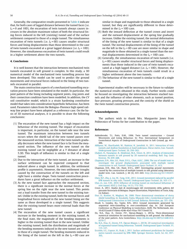
Fig. 13 shows the distribution of the bending moment in themeasured ring of the existing tunnel (left) for the LF = 10D case.It can be seen that the excavation of the new tunnel (right) causesa significant increase in the bending moment induced in the exist-ing tunnel, in particular at the right side near the new tunnel. Theresults presented in Fig. 13 and Table 2 show a gradual increase inthe absolute magnitude of the bending moment in the existingtunnel during the advancement of the face of the new tunnel. Gen-erally, due to the loss of ground during the excavation of the newtunnel, the soil mass between the tunnels has a tendency to movetowards to the new tunnel, as can be seen in Fig. 8b. On the otherhand, the ground above the existing tunnel moves downwards.These phenomena lead to an increase in the positive bending mo-ment at the right shoulder and right base regions, for the measuredring in the existing tunnel, and an increase in the absolute magni-tude of the negative bending moment at the spring line on theright. These changes are pointed out by the results presented inFig. 13 and Table 2. These results are consistent with the resultsof Kim et al. (1998), who reported that the incremental bendingmoment of an existing tunnel is at a maximum near a new tunnel.Fig. 13 indicates that the changes in bending moment at the otherlocations around the existing tunnel (location on the left side) arerelatively insignificant.
An increase of about 14.2% can be seen for the positive bendingmoment when the new tunnel face approaches the YMS distance of�1D and the increase reaches a maximum value of 383.8% at dis-tance YMS = 1.3D, which corresponds to the moment at which theshield tail of the new tunnel passes over the measured section.After that, a negligible change in the positive bending momentcan be seen (see Table 2 and Fig. 13). A similar tendency can be ob-served for the negative bending moment induced at the spring linein the measured ring in the existing tunnel (see Table 2 andFig. 13).
It should be noted that, in the existing tunnel lining, the changein the bending moment on the right side near the new tunnel isgreater than the one that occur on the left side. The maximumchanges in the absolute negative bending moment that occur atthe right and left spring lines of the existing tunnel are equal to516% and to 176%, respectively, compared to a single tunnel (seeline YMS = 1.3D in Fig. 13).
Fig. 13 and Table 2 also show that, at the final state, the magni-tude of the bending moments is higher in the existing tunnel thanin the new tunnel. The maximum positive bending moments in-duced in the existing and new tunnel are about 483.8% and91.5%, respectively, compared to the bending moment induced ina single tunnel. These values are 512.0% and 95.8%, respectively,for the minimum negative bending moment. This means that boththe distribution and magnitude of the bending moments inducedin the new tunnel are similar to those of a single tunnel.
Fig. 14 and Table 3 show a gradual increase in the bending mo-ment induced in the measured ring in the tunnel on the left duringthe simultaneous advancement of the double tunnel faces (LF = 0D).When the twin tunnel faces is 5.3D from the measured ring, thebending moments are steady. As expected, the maximum magni-tudes of the bending moments in the two tunnels are similar.
Fig. 14 and Table 4 show that the bending moments induced inthe tunnel lining on the left for the LF = 0D case are similar in shapeand magnitude to those obtained in a single tunnel, but are signif-icantly different from that determined in the LF = 10D case. Thesedifferences are important, in particular, at the tunnel side nearthe new tunnel (right).
50 N.-A. Do et al. / Tunnelling and Underground Space Technology 42 (2014) 40–51
Generally, the comparative results presented in Table 4 indicatethat, for both cases of lagged distance between the tunnel faces (i.e.LF = 0 and 10D), the excavation of twin tunnels always causes in-creases in the absolute maximum values of both the structural lin-ing forces induced in the left (existing) tunnel and of the surfacesettlement compared to those of a single tunnel. The simultaneousexcavation of twin tunnels (i.e. LF = 0D) causes smaller structuralforces and lining displacements than those determined in the caseof twin tunnels excavated at a great lagged distance (i.e. LF = 10D).However, the simultaneous excavation of twin tunnels could resultin a higher settlement above the two tunnels.
4. Conclusions
It is well known that the interaction between mechanized twintunnels excavated in soft ground is complex. In this study, a 3Dnumerical model of the mechanized twin tunnelling process hasbeen developed. This model can be used to predict the groundmovements and structural forces induced in the lining of two tun-nels excavated in parallel.
The main construction aspects of a mechanized tunnelling exca-vation process have been simulated in the model. In particular, thejoint pattern of the lining including segment joints, ring joints andtheir connection condition have been modelled. In addition, the CYsoil constitutive model, which is a strain hardening constitutivemodel that takes into consideration hyperbolic behaviour, has beenused. Parameters taken from the Bologna–Florence high speed rail-way line project have been adopted as a reference case. On the ba-sis of 3D numerical analyses, it is possible to draw the followingconclusions:
(1) The excavation of the new tunnel has a high impact on thebehaviour of the existing tunnel. The impact of excavationis important, in particular, on the tunnel side near the newtunnel. The maximum interaction between two tunnelsoccurs when the shield tail of the new tunnel passes overthe measured section. Interaction of the twin tunnels gradu-ally decreases when the new tunnel face is far from the mea-sured section. The influence of the new tunnel on theexisting tunnel can be negligible at a Y distance of about5.3D. This length of influence is similar to that of a singletunnel.
(2) Due to the interaction of the twin tunnel, an increase in thesurface settlement can be expected compared to thatinduced above a single tunnel. In addition, the settlementprofile is asymmetric. However, the two settlement troughscaused by the construction of the tunnels on the left andright have a similar shape. Twin tunnel construction proce-dures have a great influence on the surface settlement.
(3) As the new tunnel face approaches the measured section,there is a significant increase in the normal forces at thespring line on the right near the new tunnel. This pointsout a load transfer from the new tunnel to the existing tun-nel. Unlike in the existing tunnel, both the normal forces andlongitudinal forces induced in the new tunnel lining are thesame as those developed in a single tunnel. This suggeststhat the existing tunnel bears more external loads than thenew tunnel.
(4) The excavation of the new tunnel causes a significantincrease in the bending moment in the existing tunnel. Atthe final state, the magnitude of the bending moments ishigher in the existing tunnel than in the new tunnel. Unlikethe existing tunnel, both the distribution and magnitude ofthe bending moments induced in the new tunnel are similarto those of a single tunnel. The bending moments induced inthe lining of the tunnel on the left in the LF = 0D case are
similar in shape and magnitude to those obtained in a singletunnel, but they are significantly different to those deter-mined in the LF = 10D case.
(5) Both the inward deflection at the tunnel crown and invertand the outward displacement at the spring line graduallyincrease. Unlike the existing tunnel, the normal deformationof the lining of the new tunnel is similar to that of a singletunnel. The normal displacements of the lining of the tunnelon the left in the LF = 0D case are more similar in shape andmagnitude to those obtained in a single tunnel than the nor-mal displacements determined in the LF = 10D case.
(6) Generally, the simultaneous excavation of twin tunnels (i.e.LF = 0D) causes smaller structural forces and lining displace-ments than those induced in the case of twin tunnels exca-vated at a high lagged distance (i.e. LF = 10D). However, thesimultaneous excavation of twin tunnels could result in ahigher settlement above the two tunnels.
(7) The behaviour of the new tunnel is similar to that of a singletunnel.
Experimental studies will be necessary in the future to validatethe numerical results obtained in this study. Further works couldbe focused on investigating the interaction between stacked tun-nels and the influence of other elements, such as tunnel position,face pressure, grouting pressure, and the conicity of the shield onthe twin tunnel construction process.
Acknowledgments
The authors wish to thank Mrs. Marguerite Jones fromPolitecnico of Torino for her contribution to the paper.
References
Addenbrooke, T.I., Potts, D.M., 1996. Twin tunnel construction – GroundMovements and Lining Behaviour. In: Proc. International Symposium onGeotechnical Aspects of Underground Construction in Soft Ground, pp. 441–446.
Afifipour, M., Sharifzadeh, M., Shahriar, K., Jamshidi, H., 2011. Interaction of twintunnels and shallow foundation at Zand underpass, Shiraz metro, Iran. Tunnell.Underground Space Technol. 26, 356–363.
Chakeri, H., Hasanpour, R., Hindistan, M.A., Ünver, B., 2011. Analysis of interactionbetween tunnels in soft ground by 3D numerical modeling. Bull. Eng. Geol.Environ. 70, 439–448.
Chapman, D.N., Ahn, S.K., Hunt, D.V.L., Chan, A.H.C., 2006. The use of model tests toinvestigate the ground displacements associated with multiple tunnelconstruction in soil. Tunnell. Underground Space Technol. 21, 413.
Chapman, D.N., Ahn, S.K., Hunt, D.V.L., 2007. Investigating ground movementscaused by the construction of multiple tunnels in soft ground using laboratorymodel tests. Can. Geotech. J. 44 (6), 631–643. http://dx.doi.org/10.1139/t07-018.
Chen, R.P., Zhu, J., Liu, W., Tang, X.W., 2011. Ground movement induced by parallelEPB tunnels in silty soils. Tunnell. Underground Space Technol. 26, 163–171.
Choi, J.I., Lee, S.W., 2010. Influence of existing tunnel on mechanical behaviour ofnew tunnel. KSCE J. Civil Eng. 14 (5), 773–783.
Croce, A., 2011. Analisi dati di monitoraggio del rivestimento della galleria delpassante ferroviario di Bologna. Degree dissertation, Polytechnics of Turin, Italy.(in Italian).
Dias, D., Kastner, R., Maghazi, M., 2000. Three dimensional simulation of slurryshield tunnelling. In: Kusakabe, Fujita, Miyazaki (Eds.), Geotechnical Aspects ofUnderground Construction in Soft Ground. Balkema, Rotterdam, pp. 351–356.
Divall, S., Goodey, R.J., Taylor, R.N., 2012. Ground movements generated bysequential twin-tunnelling in over-consolidated clay. In: 2nd EuropeanConference on Physical Modelling in Geotechnics, Delft, The Netherlands. doi:10.4233/uuid:f71fabea-424b-42e5-93aa-701715eed17d.
Do, N.A., Dias, D., Oreste, P.P., Djeran-Maigre, I., 2013a. Three-dimensionalnumerical simulation for mechanized tunnelling in soft ground: the influenceof the joint pattern. Acta Geotechnica. http://dx.doi.org/10.1007/s11440-013-0279-7.
Do, N.A., Dias, D., Oreste, P.P., Djeran-Maigre, I., 2013b. 2D numerical investigationof segmental tunnel lining behaviour. Tunnell. Underground Space Technol. 37,115–127.
Ercelebi, S.G., Copour, H., Ocak, I., 2011. Surface settlement predictions for Istanbulmetro tunnels excavated by EPB–TBM. Springer Environ. Earth. Sci. 62, 357–365.

N.-A. Do et al. / Tunnelling and Underground Space Technology 42 (2014) 40–51 51
Hage Chehade, F., Shahrour, I., 2008. Numerical analysis of the interaction betweentwin-tunnels: influence of the relative position and construction procedure.Tunnell. Underground Space Technol. 23, 210–214.
Hasanpour, R., Chakeri, H., Ozcelik, Y., Denek, H., 2012. Evaluation of surfacesettlements in the Istanbul metro in terms of analytical, numerical and directmeasurements. Bull. Eng. Geol. Environ. 71, 499–510.
He, C., Feng, K., Fang, Y., Jiang, Y.C., 2012. Surface settlement caused by twin-parallelshield tunnelling in sandy cobble strata. J. Zhejiang University-SCIENCE A(Applied Physics & Engineering) 13 (11), 858–869, ISSN 1673-565X (Print); ISSN1862-1775 (Online).
Hefny, A.M., Chua, H.C., Jhao, J., 2004. Parametric studies on the interaction betweenexisting and new bored tunnels. Tunnell. Underground Space Technol. 19, 471.
Hunt, D.V.L., 2005. Predicting the ground movements above twin tunnelsconstructed in London Clay. Ph.D. Dissertation, University of Birmingham.
Jenck, O., Dias, D., 2004. Analyse tridimensionnelle en différences finies del’interaction entre une structure en béton et le creusement d’un tunnel àfaible profondeur. Géotechnique 54 (8), 519–528.
JSCE, 1996. Japanese Standard for Shield Tunnelling. The third edition, Tokyo.Karakus, M., Ozsan, A., Basarir, H., 2007. Finite element analysis for the twin metro
tunnel constructed in Ankara Clay, Turkey. Bull. Eng. Geol. Environ. 66, 71–79.Kasper, T., Meschke, G., 2004. A 3D finite element simulation model for TBM
tunnelling in soft ground. Int. J. Numerical Anal. Methods Geomechanics 28,1441–1460.
Kasper, T., Meschke, G., 2006. On the influence of face pressure, grouting pressureand TBM design in soft ground tunnelling. Tunnell. Underground Space Technol.21, 160–171.
Kim, S.H., Burd, H.J., Milligan, G.W.E., 1996. Interaction between closely spacedtunnel in clay. In: Proc. International Symposium on Geotechnical Aspects ofUnderground Construction in Soft Ground, pp. 543–548.
Kim, S.H., Burd, H.J., Milligan, G.W.E., 1998. Model testing of closely spaced tunnelsin clay. Geotechnique 48 (3), 375–388.
Lambrughi, A., Rodríguez, L.M., Castellanza, R., 2012. Development and validation ofa 3D numerical model for TBM–EPB mechanised excavations. Comput.Geotechnics 40, 97–113.
Leca, E., 1989. Analysis of NATM and shield tunnelling in soft ground. Ph.D.dissertation, Virginia Institute and State University, Blacksburg, Va.
Li, X., Du, S., Zhang, D., 2010. Numerical simulation of the interaction between twoparallel shield tunnels. In: Proceeding of ICPTT 2012: Better PipelineInfrastructure for a Better, Life, pp. 1521–1533.
Liu, H.Y., Small, J.C., Carter, J.P., 2008. Full 3D modeling for effects of tunnelling onexisting support systems in the Sydney region. Tunnell. Underground SpaceTechnol. 23, 399–420.
Mirhabibi, A., Soroush, A., 2012. Effects of surface buildings on twin tunnelling-induced ground settlements. Tunnell. Underground Space Technol. 29, 40–51.
Mollon, G., Dias, D., Soubra, A.H., 2013. Probabilistic analyses of tunnelling-inducedground movements. Acta Geotechnica. http://dx.doi.org/10.1007/s11440-012-0182-7.
Ng, C.W.W., Lee, K.M., Tang, D.K.W., 2004. Three-dimensional numericalinvestigations of new Austrian tunnelling method (NATM) twin tunnelinteractions. Can. Geotech. J. 41, 523–539.
Ocak, I., 2012. Interaction of longitudinal surface settlements for twin tunnels inshallow and soft soils: the case of Istanbul Metro. Environ. Earth Sci.. http://dx.doi.org/10.1007/s12665-012-2002-7.
Rijke, Q.C., 2006. Innovation of stress and damage reduction in bored tunnels duringconstruction based on a shield equilibrium model. Ph.D. dissertation, Utrecht:Delft University of Technology and Holland Railconsult.
Sagaseta, C., Sanchez-Alciturri, J.M., Gonzalez, C., Lopez, A., Gomez, P., Pina, R., 1999.Soil deformations due to the excavation of two parallel underground cavern. In:Proc. 12th European Conference Soil Mechanics and Foundation Engineering,Amsterdam, vol. 3, pp. 2125-2131.
Suwansawat, S., Einstein, H.H., 2007. Describing settlement troughs over twintunnels using a superposition technique. J. Geotech. Geoenvironment. Eng.,445–468.
Wang, J.G., Kong, S.L., Leung, C.F., 2003. Twin tunnels-induced ground settlement insoft soil. In: Proceeding of the Sino-Japanese Symposium on GeotechnicalEngineering, Beijing, China, 29–30 October 2003, pp. 241–244.
Yamaguchi, I., Yamazaki, I., Kiritani, Y., 1998. Study of ground-tunnel interactions offour shield tunnels driven in close proximity, in relation to design andconstruction of parallel shield tunnels. Tunnell. Underground Space Technol.13 (3), 289–304.
Yang, X.L., Wang, J.M., 2011. Ground movement prediction for tunnels usingsimplified procedure. Tunnell. Underground Space Technol. 26, 462–471.