THREE DIMENSIONAL NONLINEAR DYNAMIC MODELING OF A ...
19
COMPDYN 2011 III ECCOMAS Thematic Conference on Computational Methods in Structural Dynamics and Earthquake Engineering M. Papadrakakis, M. Fragiadakis, V. Plevris (eds.) Corfu, Greece, 25–28 May 2011 THREE DIMENSIONAL NONLINEAR DYNAMIC MODELING OF A VERTICALLY ISOLATED ANCIENT STATUE DISPLAYED IN A BASE ISOLATED MUSEUM BUILDING Carlo A. Castiglioni 1 , Alper Kanyilmaz 2 1 Politecnico di Milano Structural Engineering Department Piazza Leonardo da Vinci, 32 20133 Milano [email protected] 2 Politecnico di Milano Structural Engineering Department Piazza Leonardo da Vinci, 32 20133 Milano [email protected] Keywords: Seismic Isolation, Ancient Statues, Vertical Isolation Abstract: This research concerns with the question of how the seismic isolation methods can be applied efficiently to protect the ancient statues under both horizontal and vertical strong earthquake excitations. The results are achieved by carrying out nonlinear dynamical analy- ses under three dimensional earthquake ground motion data on a generic ancient statue model, considering that it is displayed in a non isolated and a horizontally isolated building. The model is developed with 8-node cubic finite elements, and placed on a rigid platform, which is modelled as an area element of rectangular shape. The isolation devices are mod- elled as non linear spring elements for the horizontal seismic isolation, and gap elements (compression only) for the vertical seismic isolation.
Transcript of THREE DIMENSIONAL NONLINEAR DYNAMIC MODELING OF A ...

COMPDYN 2011
III ECCOMAS Thematic Conference on
Computational Methods in Structural Dynamics and Earthquake Engineering
M. Papadrakakis, M. Fragiadakis, V. Plevris (eds.)
Corfu, Greece, 25–28 May 2011
THREE DIMENSIONAL NONLINEAR DYNAMIC MODELING OF A
VERTICALLY ISOLATED ANCIENT STATUE DISPLAYED IN A
BASE ISOLATED MUSEUM BUILDING
Carlo A. Castiglioni1, Alper Kanyilmaz
2
1Politecnico di Milano
Structural Engineering Department
Piazza Leonardo da Vinci, 32 20133 Milano
2Politecnico di Milano
Structural Engineering Department
Piazza Leonardo da Vinci, 32 20133 Milano
Keywords: Seismic Isolation, Ancient Statues, Vertical Isolation
Abstract: This research concerns with the question of how the seismic isolation methods can
be applied efficiently to protect the ancient statues under both horizontal and vertical strong
earthquake excitations. The results are achieved by carrying out nonlinear dynamical analy-
ses under three dimensional earthquake ground motion data on a generic ancient statue
model, considering that it is displayed in a non isolated and a horizontally isolated building.
The model is developed with 8-node cubic finite elements, and placed on a rigid platform,
which is modelled as an area element of rectangular shape. The isolation devices are mod-
elled as non linear spring elements for the horizontal seismic isolation, and gap elements
(compression only) for the vertical seismic isolation.
Carlo A. Castiglioni, Alper Kanyilmaz
1 INTRODUCTION
After the efficiency of seismic isolation technology has been proved for several types of
structures such as bridges, buildings, power plants, etc., scientists and researchers in the field
started to look for the possible ways to adapt the seismic isolation solutions and furthermore
create innovative solutions for the cultural heritage of human history and art objects. The need
to protect these objects against earthquakes was found inevitable since they are one of the
most precious possessions of the human being on the earth.
Koumousis et al. [1], in his work for the horizontal seismic isolation of the Statue of Her-
mes, has designed and proved the adequacy of the FPSTM (Friction pendulum system), after
carrying out numerical analyses on the 3D model of the statue. Borri and Grazini [2] have car-
ried out static and dynamic numerical analyses for the statue of Michelangelo’s David Statue.
They have shown that the horizontal accelerations that could be originated by even moderate
earthquakes (0.10-0.15g) can cause very high stress levels on some particular parts of the
marble statue. Grazini [3] has done rocking analysis for both the non isolated and horizontally
isolated statue models. Borri [2] and Grazini [3] have both pointed out the benefits of seismic
isolators for the seismic protection of statues. Tadahiro and Masahiko [4] have developed
seismic isolation solutions that are capable of protecting The Gates of Hell statue, which was
sculpted by Augustin Rodin and owned by National Museum of Western Art, against very
strong earthquakes such as the Great Hanshin Earthquake that occurred, in Kobe in 1995.
Yegian et al. [5], has carried out several tests and numerical analysis for the sculptures in Na-
goya Museum, with mechanical horizontal seismic isolators. In this project, the effectiveness
of the horizontal seismic isolation system is investigated for isolated and non-isolated mu-
seum buildings.
Once a rigid block starts rocking, its rotation continues smoothly from point O to O’, as
shown in the Figure 1. If it does not fail by overturning, its rotation will change direction, and
rotate otherwise, and the motion will continue in this manner, and cease some time after the
ground motion comes to an end. For the rigid block to sustain this rocking motion, the energy
released during the impact should be dissipated. The amount of this energy dissipation in-
creases with the decreasing slenderness of the block [6].
The minimum rocking impulse that causes rocking of an object has been expressed by
Calio and Marletta [7]. The minimum rocking impulse Iu, has been derived by equating the
overturning moment due to the inertia load caused by the maximum horizontal acceleration,
to the resisting moment due to the gravity as;
λ
g
h
gbIu r ==)(max
..
(1)
Considering zero damping, the maximum acceleration is given by
ωIu =max
..
(2)
Therefore the minimum impulse that starts the rocking motion of a rigid body is repre-
sented as;
Tgg
I uπλωλ 2
== (3)

Carlo A. Castiglioni, Alper Kanyilmaz
Where,
g = gravity acceleration
h = height of the center of mass of the object
b = lateral distance between the overturning point and the center of mass
λ= h/b (slenderness ratio)
ω= natural frequency of the object
T = natural period
Calio et. al [7] concluded that the object stays in full contact with the ground until the de-
sign impulse becomes equal to the minimum rocking impulse. When the minimum rocking
impulse is surpassed, the object starts rocking. Calio et al. [7] have shown that the seismic
isolation significantly contributes to the stability of the object under horizontal ground mo-
tions.
Oliveto, Calio and Greco [8], have evaluated the uplift conditions for the initiation of rock-
ing motion, considering both horizontal and vertical ground motions. They introduced a di-
mensionless parameter γ, to take into account the vertical accelerations of the ground motion.
g
v g
..
1+=γ (4)
Where
gv..
= Vertical ground acceleration (positive, when directed downwards)
g = Gravity acceleration (m/s2)
They pointed out the significance of the vertical accelerations on the minimum rocking
impulse, and expressed it through modifying the minimum rocking impulse expression;
Tgg
Iuπλ
γ
ωλ
γ
2== (5)
As it can be understood from the two expressions above, when the vertical accelerations
are directed upwards (against gravity), the minimum rocking impulse decreases, therefore the
initiation of rocking becomes easier for the object considered.
Figure 1 Rocking motion of a rigid body
This research concerns with the question of how the seismic isolation methods can be ap-
plied efficiently to protect the ancient statues subjected to both horizontal and vertical strong

Carlo A. Castiglioni, Alper Kanyilmaz
earthquake excitations. The study seeks to classify the effects of conditions deriving from dif-
ferent building types and earthquake characteristics, to design an efficient isolation system for
a particular ancient statue. To achieve the results, computer models under several earthquake
ground motion data are developed and compared for a generic ancient statue, considering that
it would have been placed either in a non isolated or horizontally isolated building.
2 ANALYSES UNDER HORIZONTAL AND VERTICAL EARTHQUAKE
EXCITATIONS
The statues are analyzed under both horizontal and vertical earthquake ground excitations,
and the properties of a three dimensional seismic isolation system are decided for the protec-
tion of the statues against the three dimensional earthquake excitations.
2.1 The methodology and Ground Motion Data Used for the Analyses
The nonlinear dynamic time history analyses are performed on the 3D finite element solid
model of an ancient statue (Figure 2) [9]
Figure 2 Ancient statue used in the numerical analysis
The model is analyzed under the three dimensional acceleration time history data of three
different earthquakes which can be seen in Table 1.
Table 1 Maximum accelerations used in the numerical analysis
The analyses are carried out in three stages. First, the acceleration time-history data of the
earthquakes are applied to a 3 storey reinforced concrete frame which represents a generic
museum building with a horizontal base isolation system. Then, the acceleration time-history
data are obtained at each floor of the building model. Finally, the acceleration time-history
data obtained from this model are given as the time history acceleration input to the ancient
statue model. The analyses are carried out in two different parts;

Carlo A. Castiglioni, Alper Kanyilmaz
1) The acceleration time-history data obtained from the non isolated building is given as
the input time history data to the statues, in which case the statues are isolated against both
horizontal and vertical excitations,
2) The acceleration time-history data obtained from the base isolated building is given as
the input to the statues, in which case the statues are isolated against only vertical excitations.
2.2 Computer Model for the Statues with Three Dimensional Base Isolation System
The model to be analyzed under the earthquake ground motion data is developed with three
dimensional 8-node finite elements, and placed on a rigid platform, which is modelled as an
area element of rectangular shape (Figure 3).
Figure 3 Three dimensional numerical model
The three dimensional seismic isolation devices are modelled as a combination of two
types of elements;
1) Non linear spring elements for the horizontal seismic isolation
2) Gap elements (compression only) for the vertical seismic isolation
Horizontal seismic isolators are placed between the floor and the rigid platform on which
the statues are placed. They are modeled as non-linear spring elements with initial stiffness ke,
post yield stiffness ky and damping element with the damping coefficient c.
Figure 4 Horizontal isolator element
The hysteresis loop of a horizontal isolator element has a bilinear shape (Figure 4). The force
deformation graph is composed of two slopes giving the 'initial' and 'yielded' stiffness respec-
tively. The initial stiffness slope corresponds to the linear deformation; whereas the yielded
stiffness slope corresponds to the plastic deformation that takes place in the isolator.

Carlo A. Castiglioni, Alper Kanyilmaz
Vertical seismic isolators are placed between the rigid platform and the base of the statues.
They are modeled as gap elements, which have positive stiffness values under compression,
and zero stiffness under tension loads. Under compression, they show a linear behavior with
spring constant k, and damping coefficient c.
2.3 Vertical Isolator Properties used in the Computer Model
The vertical isolation system consists of four springs with linear spring constant k and
damping coefficient c. In the computer model, to simulate a vertical base isolation device, a
gap (“compression only”) element is used (Figure 5). The force deformation relationship of
this element is given by;
<++
=otherwise
opendifopendkxf
..,.........0
0:)......()( (6)
Figure 5 Vertical isolator element
As it can be seen in the Figure 6, the gap elements have a linear behavior under compres-
sion, and they can not carry any tensile load. In other words, they provide linear stiffness only
under compressive loads.
Figure 6 Gap element behaviour
In the model, thanks to the self weight of the statues, these elements are initially com-
pressed. Therefore during the vertical earthquake excitations, they are expected to take action
only in the compression range. The vertical isolator elements are constrained at the vertical (z)
axis to not to permit differential displacements.

Carlo A. Castiglioni, Alper Kanyilmaz
2.4 Behaviour of Three Dimensionally Isolated Statues Displayed in a Building with-
out Horizontal Base Isolation
The analyses are carried out with different horizontal and vertical isolator elements, the prop-
erties of which can be seen in Table 2 and Table 3.
Vertical Seismic
Isolation Device
Vertical Linear
Stiffness(kv)
(N/mm)
Vertical Isolator 1 100
Vertical Isolator 2 50
Vertical Isolator 3 40
Vertical Isolator 4 30
Vertical Isolator 5 20
Table 2 Vertical isolator stiffnesses
Horizontal
Seismic
Isolation
Initial Stiff-
ness(ke)
(N/mm)
Plastic Stiff-
ness(ky)
(N/mm)
Yield
Strength(fy)
(N/mm2)
Isolator 4 1000 5 350
Table 3 Horizontal isolator properties
The analysis on the seismically isolated model of the statues are carried out under the ac-
celeration time-history data obtained from the ground floor of a non-isolated building. In the
Table 4 the reduced vertical accelerations can be seen for three different earthquakes and 5
different vertical isolators.
Maximum Vertical Ac-
celerations on the Stat-
ues (Ground Floor)
Athens 1999
(g)
El Centro 1940
(g)
Aquila 2009
(g)
Earthquake Excitation: 1,20g 0,21g 0,49g
Vertical Linear Stiff-
Stiffness (N/mm)
100 0,79 0,17 0,21
50 0,37 0,13 0,16
40 0,32 0,13 0,16
30 0,26 0,09 0,13
20 0,24 0,05 0,09
Table 4 Maximum vertical accelerations observed on the statues at the ground floor of the museum building

Carlo A. Castiglioni, Alper Kanyilmaz
Figure 7 Vertical linear stiffness-maximum vertical acceleration relation
As it can be seen in the Figure 7 and Table 4, the vertical accelerations can be reduced sig-
nificantly using vertical isolators with low stiffness values. Yet, the stiffness of the isolators
must be tuned so that they must be capable of carrying the statue, under its self weight. In
Table 5, the initial vertical displacements under the self weight of the statues can be seen.
Maximum Vertical Dis-
placements
at the Vertical Isolators
Displacements
Under Self
Weight (cm)
Vertical Linear Stiffness
(N/mm)
100 3,55
50 7,10
40 8,88
30 11,8
20 17,80
Table 5 Maximum vertical displacements observed at vertical isolators
Using four vertical isolator springs with the stiffness of 20 N/mm under the base of the
statue, the initial vertical displacement under the self weight of the statue is 17.8 cm, whereas,
it reaches up to 21.65 cm under the strongest vertical excitation (Athens 1999 Earthquake)
These results show that under three earthquake excitations, the linear vertical isolator ele-
ments perform effectively, satisfying the two necessary requirements:
- They are always under compression
- Their vertical displacement values are within the limits that available products in the
market can provide.

Carlo A. Castiglioni, Alper Kanyilmaz
Figure 8 Vertical isolator force-deformation graph, Athens 1999 Earthquake
Figure 9 Vertical isolator force-deformation graph, El Centro 1940 Earthquake
From Figure 8 to Figure 10, the link-deformation graphs of the vertical isolator elements,
obtained under three different earthquake ground motion can be seen. They represent the be-
havior of the vertical isolation system placed under each statue and composed of four isolator
elements of 20 N/mm linear stiffness.

Carlo A. Castiglioni, Alper Kanyilmaz
Figure 10 Vertical isolator force-deformation graph, Aquila 2009 Earthquake
In Figure 11, the displacements at the vertical isolators under the self weight of the statue
obtained under three different earthquake ground motion can be seen. All the deformations
observed refer to compression condition in the vertical isolation elements.
Figure 11 Stiffness-Displacement relation for the vertical isolation
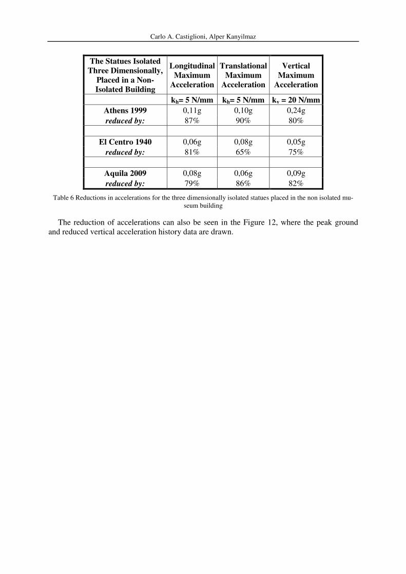
From the results of the numerical analyses, it can be seen that the accelerations in any di-
rection can be reduced significantly utilizing a three dimensional seismic isolation system.
From Table 6, the amount of reduced accelerations and the percentage of reductions can be
observed.
Carlo A. Castiglioni, Alper Kanyilmaz
The Statues Isolated
Three Dimensionally,
Placed in a Non-
Isolated Building
Longitudinal
Maximum
Acceleration
Translational
Maximum
Acceleration
Vertical
Maximum
Acceleration
kh= 5 N/mm kh= 5 N/mm kv = 20 N/mm
Athens 1999 0,11g 0,10g 0,24g
reduced by: 87% 90% 80%
El Centro 1940 0,06g 0,08g 0,05g
reduced by: 81% 65% 75%
Aquila 2009 0,08g 0,06g 0,09g
reduced by: 79% 86% 82%
Table 6 Reductions in accelerations for the three dimensionally isolated statues placed in the non isolated mu-
seum building
The reduction of accelerations can also be seen in the Figure 12, where the peak ground
and reduced vertical acceleration history data are drawn.

Carlo A. Castiglioni, Alper Kanyilmaz
Figure 12 Reductions in Accelerations
2.5 Behaviour of Vertically Isolated Statues Displayed in a Building with Horizontal
Base Isolation
In a base isolated museum building, placing the statues upon an additional local horizontal
isolation system does not help reducing the accelerations, in contrary, since the frequency
contents of the building and the isolated platform of statues become similar to each other, the
seismic risk for the statues increase, because of a possible resonance problem. Therefore in
order to achieve an effective three dimensional isolation system in a base isolated museum

Carlo A. Castiglioni, Alper Kanyilmaz
building, the rigid platform on which the statues are placed is restrained to the ground hori-
zontally, and vertical seismic isolators are mounted between the statue and the rigid platform
(Figure 13).
Figure 13 Vertical Isolation Model
For each statue, four vertical seismic isolator elements are used with linear stiffness values
of 20 N/mm. From Table 7, the amount of reduced accelerations and the percentage of reduc-
tions in each direction can be seen. Note that in this table, the reductions in the horizontal ac-
celerations are obtained thanks to the horizontal base isolation of the building.
Vertically Isolated
Statue Placed in a
Base Isolated Building
Longitudinal
Maximum
Acceleration
Translational
Maximum
Acceleration
(g)
Vertical
Maximum
Acceleration
(g)
Athens 1999 0,17g 0,19g 0,24g
reduced by: 80% 81% 80%
El Centro 1940 0,17g 0,13g 0,05g
reduced by: 46% 41% 75%
Aquila 2009 0,08g 0,04g 0,09g
reduced by: 81% 91% 82%
Table 7 Reductions in accelerations for the vertically isolated statues placed in the base isolated museum build-
ing
From Figure 14, the reductions of maximum vertical accelerations that the statues experi-
ence with decreasing spring stiffness can be seen.

Carlo A. Castiglioni, Alper Kanyilmaz
Figure 14 Vertical linear stiffness-maximum vertical acceleration relation
Therefore it can been concluded that in a base isolated museum building, adopting a verti-
cal seismic isolation system, the accelerations that the statues experience in any direction can
be lowered significantly.
3 ROCKING ANALYSES
If the vibrations are exceeded above a certain limit, the rigid blocks start “rocking”. Stati-
cally, when the overturning moment caused by earthquake forces reaches the resisting mo-
ment due to the self weight, the object starts to rock. This condition can be demonstrated with
the following expression for a statue shown in Figure 15 :
resistinggoverturnin MM = (7)
)()( vh mamgbmah ±= (8)
where,
h = Height of the center of mass of the object
b = Lateral distance between the overturning point and the center of mass of the object
m = Mass of the object
g = Gravity acceleration
ah = Horizontal acceleration
av = Vertical acceleration
Figure 15 Ancient statue rigid body model

Carlo A. Castiglioni, Alper Kanyilmaz
However, since earthquake forces are impulsive, the static approach may not give satisfy-
ing results.. Therefore, the accelerations that can start the rocking of a rigid body is estimated
using “Impulsive Loading Approach”, in which the minimum impulse that a specific rigid
block can tolerate is compared with the impulse caused by the maximum accelerations of the
earthquake excitations.
3.1 Initiation of Rocking Motion of a Rigid Block under Impulsive Loads
A rigid block, subjected to the horizontal and vertical accelerations, can either remain in
full contact with the ground or it uplifts and starts rocking. During this motion, if the accelera-
tion impulse caused by the earthquake forces becomes larger than the minimum overturning
impulse of the system, the object overturns. Otherwise, it continues rocking until the ground
motion comes to the end (Figure 16). The object’s full contact to the ground can be kept, if
the magnitude of the impulse remains smaller than the minimum impulse required for uplift
for the object [8].
While adopting an isolation solution for the protection of ancient statues, attention must be
paid to the initiation of uplift because, once the object begins rocking, it starts to have impacts
while rotating from one of its corners to the other, and this action may cause serious damage
to an ancient statue. In this study, assessment of the horizontal and vertical accelerations that
allow the statue to remain in full contact with the ground is carried out in presence of suitable
vertical isolation elements.
Figure 16 Rocking and overturning
For the tuning of accelerations through seismic isolation devices, the minimum impulse
that can start the rocking motion of the statue is calculated and compared with the impulse
caused by maximum earthquake accelerations, which is called as “design impulse”. Finally,
interaction diagrams between horizontal and vertical accelerations for the specific ground mo-
tions are presented. Examining these diagrams, the allowable horizontal and vertical accelera-
tions that can keep the statue model in full contact with the ground can be decided.
The minimum impulse that initiates the rocking motion of an object is called as the mini-
mum uplift impulse [8]. It depends on the object’s geometric properties (slenderness), natural
frequency, (stiffness and mass), and the vertical ground motions. Comparing the minimum
impulse of a particular object with the impulse caused by the earthquake excitations, the prob-
ability for the initiation of rocking can be foreseen.
In the absence of damping, the minimum uplift impulse of a structure can be found accord-
ing to the equation (5) in section 1, which shows that, the minimum uplift impulse decreases
with the increasing natural frequency and slenderness. Also, the vertical accelerations have a
direct effect on the motion. From the equation (5), it can be concluded that,
- More rigid structures (with higher natural frequency) are easier to uplift, than the flexible
ones.

Carlo A. Castiglioni, Alper Kanyilmaz
- More slender structures (higher h/b ratio) are easier to uplift than the less slender ones
- The upward vertical accelerations reduce the minimum uplift impulse, which results in a
lower resistance to the uplift.
Thus, it can be understood that vertical accelerations of the earthquakes are very important
for the uplift resistance of the object. The higher values the vertical accelerations have in the
upward direction, the easier is the initiation of the uplift.
For instance, if the maximum vertical accelerations of an earthquake equals to –g, the ver-
tical excitation parameter, γ (see equation 4) becomes zero, so does the minimum uplift im-
pulse, Iu. This practically means “zero” resistance to uplift, therefore in such a case, even a
slight horizontal impulse would be enough to start rocking of the object.
Therefore the effect of the magnitude of maximum vertical accelerations to the uplift resis-
tance of the statue is investigated. To compare with the minimum uplift impulse of the statue,
the design impulse caused by the horizontal accelerations of the earthquake excitation must be
calculated. After making a comparison between these two values, the probability for the ini-
tiation of rocking for the particular object can be estimated.
3.2 Design Impulse
The maximum impulse caused by the horizontal earthquake excitation considered for the
analysis is called the design impulse. To estimate the magnitude of the design impulse, the
time integral of the earthquake force p(t) should be calculated.
Earthquake Force: )()(..
tumtp h= (9)
Magnitude of Design Impulse: ∫2
1
)(
t
t
dttp (10)
This integral can be estimated as the multiplication of the mass of the statue and the area un-
der the acceleration time history graph between two successive time instants, corresponding to
the maximum horizontal acceleration. As a reasonable estimation, the triangular area that is
drawn in the acceleration time history diagram in Figure 17 gives the magnitude of impulse
for unit mass.
Figure 17 Impulse calculation graph
)(2
1. 12max ttaI d −= (for unit mass)

Carlo A. Castiglioni, Alper Kanyilmaz
In the analyses, the comparison between the design impulse and the minimum rocking im-
pulse of the statue is made by considering three different earthquake data, the properties of
which are presented in the previous sections.
The comparison between the magnitude of the design impulse and the minimum uplift im-
pulse shows if the object begins to rock or stays in full contact with the ground.
- If the design impulse is smaller than the minimum uplift impulse, the statue stays in full
contact with the ground
Id<Iu → Full Contact
- If the design impulse is larger than the minimum uplift impulse, the object starts to rock-
ing
Id>Iu →Rocking
To generalize the results for all three of the earthquake data, the same calculation proce-
dure is applied with particular parameters of each analyses, and the results are presented as
interaction graphs between the horizontal and vertical accelerations. The interaction graphs
are shown in the figures 19,20 and 21. The trend line shows the intersection of the magnitudes
of maximum horizontal and vertical accelerations below which the statue stays in full contact
with the ground, during the specific earthquake motion. The points above the trend line repre-
sent the acceleration values that are sufficient to start the rocking motion.
Figure 18 Interaction diagram of horizontal and vertical accelerations for the initiation of rocking

Carlo A. Castiglioni, Alper Kanyilmaz
Figure 19 Interaction diagram of horizontal and vertical accelerations for the initiation of rocking
Figure 20 Interaction diagram of horizontal and vertical accelerations for the initiation of rocking
4 CONCLUSIONS
In this study, the effective ways to protect the ancient statues against three dimensional
earthquake ground motions are investigated through seismic isolation methods. Several nu-
merical analyses are carried out to understand which type of isolation system is suitable for
each case. It is seen that both the horizontal and vertical accelerations transmitted to the stat-
ues can be reduced significantly, with a combination of vertical isolators at the base of the
statues and horizontal base isolation system of the building. If the museum building in which
the statues are to be displayed is not base isolated, then a three dimensional isolation system
must be adopted for the statues.
Rocking analyses are carried out with the results obtained in each case. The results of the
rocking calculations for each earthquake data are presented as interaction graphs to show the
allowable accelerations under which the statues remain in full contact with the ground, and

Carlo A. Castiglioni, Alper Kanyilmaz
suffers no damage due to the impacts during rocking. Principally, it is understood that the ver-
tical earthquake excitations play a very important role on the initiation of uplift of the statues.
It is shown that ancient statues can be protected against three dimensional earthquake exci-
tations effectively, when a seismic isolation system is designed according to their particular
material and geometrical properties and the characteristics of the building in which they are to
be displayed.
REFERENCES
[1] Vlasis Koumousis. Seismic Isolation of the Statue of Hermes of Praxitelis at the New
Museum of Olympia. İstanbul : s.n., 2007
[2] Andrea Borri, Andrea Grazini. Diagnostic Analysis of the Lesions and Stability of
Michelangelo's David, Report, La stabilita' delle grandi statue, Il David di Michelangelo,
2005.
[3] Andrea Grazini. La stabilita' delle grandi statue, Il David di Michelangelo, Report, Mo-
dellazione ed Analisi Strutturale del David di Michelangelo 2005
[4] Yano Tadahiro, Higashino Masahiko. The rehabilitation of the Gates of Hell and its
Seismic Strengthining by Base Isolation. 2000.
[5] Mishac Yegian, Ece Eseller, Seda Gökyer, Keith Hall, David Whelpley. Evaluation of a
Mechanical Isolator for Protecting Four MFA Sculptures Against Earthquakes in Na-
goya Japan, 2008.
[6] Nicos Makris, Dimitrios Konstantinidis. The Rocking Spectrum and the Shortcomings
of Design Guidelines. 2001.
[7] Ivo Calio, M. Marletta. Passive Control of the Seismic Rocking Response of Art Ob-
jects. Engineering Structures, Elsevier, 2003.
[8] Giuseppe Oliveto, Ivo Calio, Annalisa Greco. Large Displacement Behavior of a Struc-
tural Model with Foundation Uplift under Impulsive and Earthquake Excitations. s.l. :
John Wiley & Sons, Ltd., 2002.
[9] SAP2000 Advanced 14.1.0 Structural Analysis Program