THORKOM - Cooper Industries€¦ · V-LOK POSI-LOK RECEPTACLE THORKOM connectors can be mated and...
11
THORKOM n Con ro Service
Transcript of THORKOM - Cooper Industries€¦ · V-LOK POSI-LOK RECEPTACLE THORKOM connectors can be mated and...
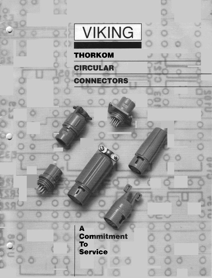
THORKOM
n
Con ro Service

STEPS IN SELECTING THORKOM CONNECTORS
To assist you in selecting and ordering our connectorsfor your specific application, we have some suggested guidelines to follow: 1. Type of cable to be used
(jacketed, shielded, coil, straight, AWG of individual wire)
2. Where connector is used (bulkhead, cable to cable)
3. What are the current require- ments (volts, amps, etc.)
4. Size of connector and type (number of contacts, right angle or straight)
5. Strain relief (yes or no. if yes, type of backshell)
6. Type of approval connector needs to meet (U.L., CSA, VDE)
All these questions, when answered, will help expedite the placing of your order and ensure your receiving the correct product.
MATERIALS AND FINISHES
Connector Housing: High Strength Thermoplastic, U.L. 94V-2 approved or "High Temperature Resistant" thermoplastic material for autoclaving processes*, U.L. 94V-0 approved
0 Sealed Gasket: Neoprene Rubber Screw Machined Contacts: Copper Alloy (stainless steel hood over socket tines), gold plated per MIL-G-45204B Type II, Grade C over nickel (.000010" gold) or tin plated per MIL-T-10727A Type I, bright finish (.00020OU min.) Cable Clamps: Aluminum, Chemical Conversion Coating Panel Mount Retaining Ring: Carbon Steel Strain Relief and Cable Clamp Backshells: High Strength Thermoplastic, u.L. 94V-2 approved Stove Pipe and Tie Strap Backshells: High Density Polyethylene, U.L. 94V-2 approved Contacts No. 22 (accepts 22-24-26 AWG wire)
'Nonstandard material, please contact factory for price and delivery.
FEATURES
Available in various shell sizes, high density contact arrangements and mounting styles Quick connect and dis- connect with either POSI-LOK or V-LOK coupling U.L. approved, 94V-2 "High temperature resistant" thermoplastic for autoclav- ing processes
• Low unit cost Durable and competitively priced screw machined contacts Screw machined dip solder contacts Various backshell and strain relief options Environmental molded cable assemblies
U.L. listed under U.L. File No. E74125
@' CSA certified under File No. LR61763
PERFORMANCE CHARACTERISTICS
Current Rating on Contacts: 5 Amperes Dielectric Withstanding Volt- age: 1500 VRMS Maximum @ Sea Level, 600 VRMS @ 70,000 feet (21,336 meters) Ambient Temperature: -55' to +125O C. (-67' to +257O F.) Insulation Resistance: 5,000 Megohms Minimum
• Contact Retention: 10 Ibs. (4.5 kg) axially after one cycle.
APPLlCATlONS
THORKOM connectors have been used in a broad variety of commercial and industrial applications. Some of these include: Computer Equipment Medical Instrumentation
~!~~~~y,"ations Marine Aviation Process Control Audio Equipment Consumer Electronics Agriculture
THORKOM CONNECTORS, BACKSHELLS AND CONTACTS STRAIN RELIEF STRAIN RELIEF BACKSHELLS BACKSHELLS
CRIMP PINS
-- DIP SOLDER -- DUMMY FlUER -am
SQUARE FLANGE RECEPTACLE

V-LOK POSI-LOK RECEPTACLE
THORKOM connectors can be mated and unmated by means of two locking styles: Insert backshell and strain relief on cable V-LOK or POSI-LOK. before inserting contacts into insulator.
The plugs used for both locking styles are identical. The receptacles differ in the latch Align stand-offs on insulator with slots on
PLUG strain relief and mate them together.
Slide backshell over strain relief to meet threads. Do not turn backshell before this, or
RECEPTACLE you may disengage strain relief from correct position. When backshell is against insulator threads push and turn in the same motion as
Continue to turn backshell until it bottoms out on insulator. (Hand tight only)
TO RETAIN
TO MATE PLUGS AND TO UNMATE PLUGS FROM RECEPTACLES: POSI-LOK RECEPTACLES: 1. Turn plug so "keyed" insulator 1. Squeeze finger grips to flex plastic
coupling area. The locking tabs will 2. Push plug into receptacle until deflect outward and unlock. locking tabs (A) snap into undercuts 2. Pull plug from receptacle.
TO UNMATE PLUGS FROM V-LOK RECEPTACLES: Simply pull plug from receptacle. Do not turn or twist. Do not use hand tools.
ORDERING INFORMATION CONNECTORS - A connector order consists of connector and back- CONTACTS - Contacts for Thorkom connectors must be ordered
shell. To order, use the chart shown below and combine component part separately. Ordering information for contacts is provided on pages 4 and numbers as required to suit your needs. 7. To order, use the chart shown below.
THORKOM ' I ' r B Bulkhead (7 & 12 only) (pg. 5) A N Plug and Receptacle (pg. 5-6) 1 I K Bulkhead or Plug (24 pos. only) (pg.5) 1 F Square flange (24 pos. only) (pg. 6)
R Receptacle (pg. 5-7) P Plug (pg. 3-4)
07 7 Contact positions A 12 12 Contact positions 24 24 Contact positions
BACKSHELLS: (pg.8-9) 1'0 Cable Backshell 1 * I Without Backshell 1'2 Stove Pipe Backshell 1'3 Tie Strap Backshell 1'5 Long Cable Clamp Backshell 2'1 Strain Relief, 7 position, Cable Dia. .l50 - .I85 2*2 Strain Relief, 7 position, Cable Dia. .l9O - .220 2'3 Strain Relief, 7 position, Cable Dia. .240 - .255 2'4 Strain Relief, 12 position, Cable Dia. .230 - .260 2'5 Strain Relief, 12 position, Cable Dia. .275 - ,300 2'6 Strain Relief, 12 position, Cable Dia. ,335 - .345
LOCKING STYLE: (use for receptacle only)
P-POSI-LOK V-V-LOK
' Color 0 - Gray 1 - Black
1- CONTACT PLATING: Au Gold Plate T Tin Plate
I TYPE OF CONTACT: (pgs. 4 and 7)
TS-100 Screw Machined Contact (Loose)
TP-100 Screw Machined Pin Contact (Loose)
DS-100 Dip Solder Socket Contact (Loose)
DP-100 Dip Solder Pin Contact (Loose)
TD-200 Dummy Filler
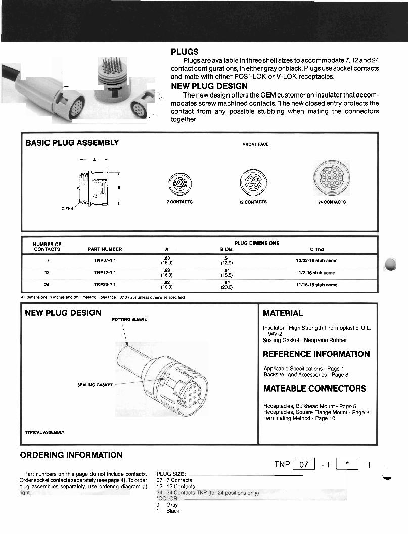
PLUGS Plugs are available in three shell sizes to accommodate 7,12 and 24
contact configurations, in either gray or black. Plugs use socket contacts and mate with either POSI-LOK or V-LOK receptacles. - NEW PLUG DESIGN
<', The new design offers the OEM customer an insulator that accom- ' modates screw machined contacts. The nem closed entry protects the , contact from any possible stubbing when mating the connectors i together.
BASIC PLUG ASSEMBLY FRONT FACE
h- A 1 35: c== L " L I 0 @ I 7 CONTACTS 12 CONTACTS 24 CONTACTS
C Thd
NUMBER OF PLUG DIMENSIONS CONTACTS PART NUMBER A B Dia. C Thd
7 TNW7-1 1 .63 .51 (16 0) (12 9)
13/32-16 stub acme
12 TNP12-I 1 .63 .61 (160) (15 5)
1/2-16 stub
24 TKP24-1 1 .63 .a1 (16 0) (20 6)
11/16-16 stub acme
All dimensions in inches and (millimeters). Tolerance * .010 (.25) unless otherwise specified.
ORDERING INFORMATION
Part numbers on this page do not include contacts. PLUG SIZE: Order socket contacts separately (see page 4). To order 07 7 Contacts plug assemblies separately, use ordering diagram at 12 12 Contacts
'"' " ' ' 7 ' - NEW PLUG DESIGN
POlTING SLEEVE
\ \
SEALING GASKET
TYPICAL ASSEMBLY
0 Gray 1 Black
MATERIAL
Insulator - High Strength Thermoplastic, U.L. 94V-2
Sealing Gasket - Neoprene Rubber
REFERENCE INFORMATION
Applicable Specifications - Page 1 Backshell and Accessories - Page 8
MATEABLE CONNECTORS
Receptacles, Bulkhead Mount - Page 5 Receptacles, Square Flange Mount - Page 6 Terminating Method - Page 10
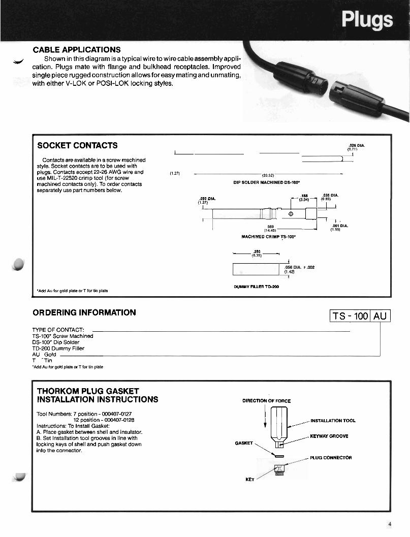
CABLE APPLICATIONS d Shown in this diagram isa typical wire to wirecableassemblyappli-
cation. Plugs mate with flange and bulkhead receptacles. Improved single piece rugged construction allowsfor easy mating and unmating, with either V-LOK or POSI-LOK locking styles.
L
SOCKET CONTACTS .WE DIA.
i (0.71)
1 Contacts are available in a screw machined 1
style. Socket contacts are to be used with plugs. Contacts accept 22-26 AWG wire and (1.27) use MIL-T-22520 crimp tool (for screw (20.52)
machined contacts only). To order contacts DIP SOLDER MACHINED DS-100. separately use part numbers below.
.155 .035 DIA. .050 DIA.
(1.27) (3.94) (0.89)
i r 142 @
'+i.,DlA. (14.45) (1 55)
MACHINED CRIMP TS-100. ,- '::L 7, (1.42)
*.m
DUMMY FILLER TD-200 'Add Au for gold plate or T for tin plate
<
ORDERING INFORMATION I T S - IOOIAUI TYPE OF CONTACT: TS-100' Screw Machined DS-100* Dip Solder TD-200 Dummy Filler AU Gold T -Tin 'Add Au for gold plate or T for tin plate
THORKOM PLUG GASKET INSTALLATION INSTRUCTIONS DIRECTION OF FORCE
Tool Numbers: 7 position - 000407-0127 12 position - 000407-0128
I l k INSTALLATION TOOL
Instructions: To Install Gasket: A. Place gasket between shell and insulator. B. Set installation tool grooves in line with KEYWAY GROOVE
locking keys of shell and push gasket down GASKET into the connector. \ PLUG CONNECTOR
KEY
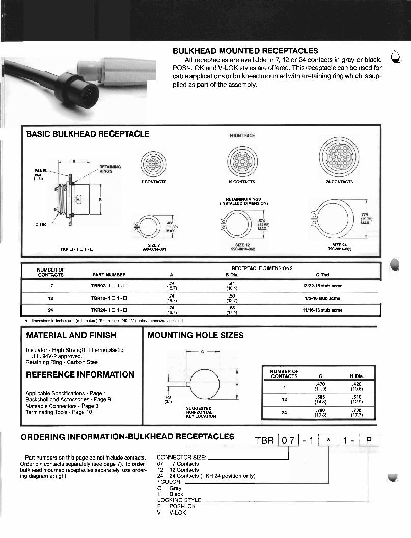
BULKHEAD MOUNTED RECEPTACLES All receptacles are available in 7, 12 or 24 contacts in gray or black. Q
POSI-LOK and V-LOK styles are offered. This receptacle can be used for cableapplicationsor bulkhead mounted with a retaining ring which issup plied as part of the assembly.
BASIC BULKHEAD RECEPTACLE
PANEL ,064 (1.63)
C rnd
7 CONTACTS
SIZE 7 TKRO-101-• 9906014dB1
12 CONTACTS
RETAINING RINGS (INSTALLED DIMENSION)
24 CONTACTS
SlZE 24 9906014663
I NUMBEROF CONTACTS PART NUMBER
RECEPTACLE DIMENSIONS B Dia. C Thd
7 TBRO7- 1 1 - .74 .41 (18.7) (10.4) 13/32-16 stub acme
12 T B R l 2 - 1 0 1 - 0 .74 .50 (18.7) (12.7) 1/2-16 stub acme
I 24 TKR24- 1 1 - q .74 .68 (18.7) (17.4) llM6-16 stub acme 1
All dimens~ons In inches and (millimeters). Tolerance r ,010 (.25) unless otherwise specified.
ORDERING INFORMATION-BULKHEAD RECEPTACLES TBR 107 - -1 1 wl
MATERIAL AND FINISH
Insulator - High Strength Thermoplastic, U.L. 94V-2 approved.
Retaining Ring - Carbon Steel
REFERENCE INFORMATION
Applicable Specifications - Page 1 Backshell and Accessories - Page 8 Mateable Connectors - Page 3 Terminating Tools - Page 10
Part numbers on this page do not include contacts. CONNECTOR SIZE: ' Order pin contacts separately (see page 7). To order 07 7 Contacts bulkhead mounted receptacles separately, use order- 12 1 2 Contacts ing diagram at right. 24 24 Contacts (TKR 24 position only)
*COLOR: 0 Gray 1 Black LOCKING STYLE: P POSI-LOK V V-LOK
MOUNTING HOLE SIZES
,125 (3.1)
SUGGESTED HOIRZONTAL KEY LOCATION
NUMBER OF CONTACTS G H Dla.
7 .470 .420 (1 1.9) (10.6)
12 .565 .510 (14.3) (12.9)
24 .760 .700 (1 9.3) (17.7)
L

SQUARE FLANGE MOUNTED RECEPTACLES 0 All square flange recepfaclesare available in 7,12 or 24 contacts in '.
gray or black. Both POSI-LOK and V-LOK latching styles are offered.
SQUARE FLANGE
rAi RECEPTACLE
- .750 (19.05)
,096 (2.44) ' 2 SLOTS 1 r .17 (4.32) '[@-k12.70)
.096 (2.44) ' DIA HOLE N P
7 CONTACTS
FRONT FACE
, gs (22.2)
I 0% (2.44) 7 '2 SLOTS 1 ..T@i- (4.39)
,096 (2.44) DIA HOLE N P
12 CONTACTS
.096 (2.44) DIA HOLE N P
k 1.000 (25.4) SO I l, , .m (2.44) , i 1 2 SLOTS 1
24 CONTACTS
12 TNRl2- 1 1 - .74 .50 (18.7) (12.7) 1/2-16 stub acme
24 TFR24- 1 1 - 0 .74 .687 (18.7) (17.4) 11116-16 stub acme
All dimens~ons in inches and (millimeters). Tolerance + ,010 (.25) unless otherwise specified.
9 NUMBER OF CONTACTS
SQUARE FLANGE RECEPTACLE DIMENSIONS PART NUMBER A B Dia. C Thd
7 TNR07- 1 1 - .74 .406 (18.7) (10.3) 13/32-16 stub acme
Part numbers on this page do not include contacts. CONNECTOR SIZE: Order pin contacts separately (see page 7). To order 07 7 Contacts square flange receptacles separately, use ordering 12 12 Contacts 3 diagram at right. 24 24 Contacts (TFR 24 position only)
*COLOR: 0 Gray 1 Black LOCKING STYLE: P POSI-LOK V V-LOK
MATERIAL
Insulator- High Strength Thermoplastic, U.L. 94V-2 approved.
REFERENCE
Applicable Specifications - Page 1 Backshell and Accessories - Page 8 Mateable Plugs - Page 3 Terminating Tools - Page 10
MOUNTING HOLE SIZES
t-'I
i ;p 4 HOLES SQUARE FLANGE
NUMBER OF CONTACTS H Dia. I
7 .420 .500 (1 0.6) (1 2.7)
12 .510 .625 (12.9) (15.8)
24 .700 .750 (1 7.7) (19.0)

CONTACT PATTERNS FRONT FACE RECEPTACLES
,0425 t ,001
THORKOM subminiature cylindricals offer (1.08 * ,025)
high contact density within minimum shell ,0425 t .w1 sizes. Shown here are contact hole patterns for the three THORKOM shell sizes.
,063 a ,001 ,085 + .om
DlA ( N P ) (2.162 .05) .063* ,001
DIA (NP) a .Oz5) _/ L.0736+ .MI0 (1.M) r ,025)
(1.87 + ,025)
I275 * .W20 (3.24 * ,050)
(5.40 * .050)
7 PIN 12 PIN 24 PIN
PIN CONTACTS .m DIA .14 (0.76)
(3.56) .W5 DIA ry I r il% l 3 ? y 1 & Pin contacts are available in a screw ma-
chined type. Pins are typically used with f receptacles. Contacts accept 22-26 AWG wire
0 .061 DIA -'?Y7~%) (15.03) DUMMY FILLER -7 and use MIL-T-22520 crimp tool (screw 592
machined contact only). To order contacts TD-IL~~.
separately, use part numbers below. MACHINED CRIMP TP-100'
L 1
.028 DIA (0.71) DIP SOLDER MACHINED
'Add Au for gold plate or T for tin plate DP-1W.
ORDERING INFORMATION 2 To order backshells separately, use ordering dia-
gram below. See page 2 for ordering backshells as part of complete assemblies.
I I
TYPE OF PIN CONTACT: TP-100' Screw Machine Pin Contact DP-loo* Dip Solder Pin Contact TD-200 Dummy Filler AU Gold T Tin
This diagram illustrates a bulkhead mounted STRAIN RELIEF BACKSHELL receptacle with attached strain relief backshell.
DIP SOLDER APPLICATIONS SQUARE FLANGE
Using dip solder contacts, THORKOM re- .
ceptacles may be soldered directly into printed .7754 (18.7) iy circuit boards or flexible circuitry. The dip
- -- solder contact is also used as a solder post -- I --:+ - -
for pressure or temperature transducer applications. 7
P.C. BOARD MOUNT BULKHEAD RECEPTACLE SQUARE FLANGE RECEPTACLE WROUGH MOUNTING PANEL
_I
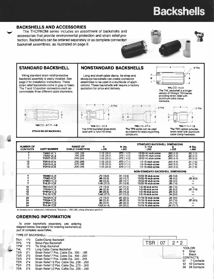
BACKSHELLS AND ACCESSORIES The THORKOM series includes an assortment of backshells and -- -
-I accessories that provide environmental protection and strain relief pro- tection. Backshells can be ordered separately or as complete connec backshell assemblies, as illustrated on page 9.
b
STANDARD BACKSHELL DIMENSIONS NUMBER OF RANGE O F A B Dia. C Thd D E Dia. CONTACTS PART NUMBER CABLE DIAMETERS *.MO k.010 k.005 k.005 i.005
7 TSR07-201 .150/.185 1.12 (28.0) 572 (14.5) 13/32-16 stub acme .265 (6.6) .25 (6.3) 7 TSR07-202 .I 901.220 1.12 (28.0) .572 (14.5) 13/32-16 stub acme .265 (6.6) .25 (6.3) 7 TSR07-203 .2401.255 1.12 (28.0) 572 (14.5) 13/32-16 stub acme .265 (6.6) .25 (6.3)
12 TSR12-204 .230/.260 1.12 (28.0) .672 (17.1) 1/2-16 stub acme .345 (8.6) .31 7 8) 12 TSR12-205 .275/.300 1.12 (28.0) .672 (17.1) 1/2-16 stub acme .345 (8.6) .31 1718) 12 TSR12-206 .335/.345 1.12 (28.0) .672 (17.1) 1/2-16 stub acme .345 (8.6) .31 (7.8)
NON-STANDARD BACKSHELL DIMENSIONS
7 TKH07-100 .71 (18.0) .51 (1 2.9) 13/32-16 stub acme .23 (5.8) - 7 TPSO7-102 .90 (22.8) .50 (1 2.7) 13/32-16 stub acme .18 (4.5) .25 (6.3) 7 TPW07-103 .90 (22.8) .SO (1 2.7) 13/32-16 stub acme .18 (4.5) - 7 THL07-105 1.46 (37.0) .51 (12.9) 13/32-16 stub acme .30 (7.6) -
12 TKH12-100 .71 (18.0) .6l (15.5) 1/2-16 stub acme .30 (7.6) - 12 TPSI2-102 .90 (22.8) .So (15.2) 1/2-16 stub acme .25 (6.3) .3l (7.8) 12 TPW12-103 .90 (22.8) 1/2-16 stub acme .25 (6.3) - .60 (15.2) 12 THLl2-105 1.48 (37.5) .61 (15.5) 1/2-16 stub acme .34 (8.6) - 24 TKH24-100 .71 (18.0) .81 (20.5) 11/16-16 stub acme .34 (8.6) - 24 TPS24-102 .90 (22.8) .80 (20.3) 11/16-16 stub acme .31 (7.8) .37 (9.3) 24 TPW24-103 .90 (22.8) .a0 (20.3) 11/16-16 stub acme .31 (7.8) - 24 THL24-105 1.63 (41.4) .El (20.5) 11/16-16 stub acme .50 (1 2.7) -
L
STANDARD BACKSHELL
Viking standard strain relieflprotective backshell assembly is easily installed. See page 2 for installation instructions. These strain relief backshells come in gray or black. The 7 and 12 position connectors each ac- commodate three different cable diameters.
All dimensions in inches and (millimeters). Tolerance r ,010 (.25) unless otherwise specified
NONSTANDARD BACKSHELLS
Long and short cable clamp, tie-strap and I@ stovepipe backshells can create connector D B
assemblies to be used in a multitude of appli- 1 0 k!iEiiYcThd -A cations. These backshells will require a factory quotation for price and delivery. T H L O O - 1 0 5
The THL backshell is a longer version of Viking's TKH series, providing strain relief with aluminum cable clamp hardware.
ORDERING INFORMATION
T S R 0 0 - 2 0 0 - 1 4 T P W O O - 1 0 3 TPSOO-lb2 T K H 0 0 - 1 0 0 TheTPW backshell givesstrain The TPS series can be used The TKH option provides
STRAIN RELIEF BACKSHELL relief witti a nylon tie strap. asasleevefor applying potting strain relief with aluminum compound. cable clamp hardware.
1
To order backshells separately, use ordering diagram below. See page 2 for ordering backshells as part of complete assemblies.
TYPE OF BACKSHELL: I I
TKH 1'0 TPS 1'2 TPW 1'3
,: THL 1'5 TSR 2'1 TSR 2'2 TSR 2'3 TSR 2'4 TSR 2'5 TSR 2'6
Cable-Clamp Backshell Stove Pipe Backshell t i e Strap Backshell Long Cable Clamp Backshell Strain Relief 7 Pos. Cable Dia. .l50 - .I85 Strain Relief 7 Pos. Cable Dia. .l9O - .220 Strain Relief 7 Pos. Cable Dia. .240 - .255 Strain Relief 12 Pos. Cable Dia. ,230 - .260 Strain Relief 12 Pos. Cable Dia. ,275 - .300 Strain Relief 12 Pos. Cable Dia. .335 - .345
*COLOR: 0 Gray 1 Black CONTACTS: 07 7 Contacts 12 12 Contacts 24 24 Contacts
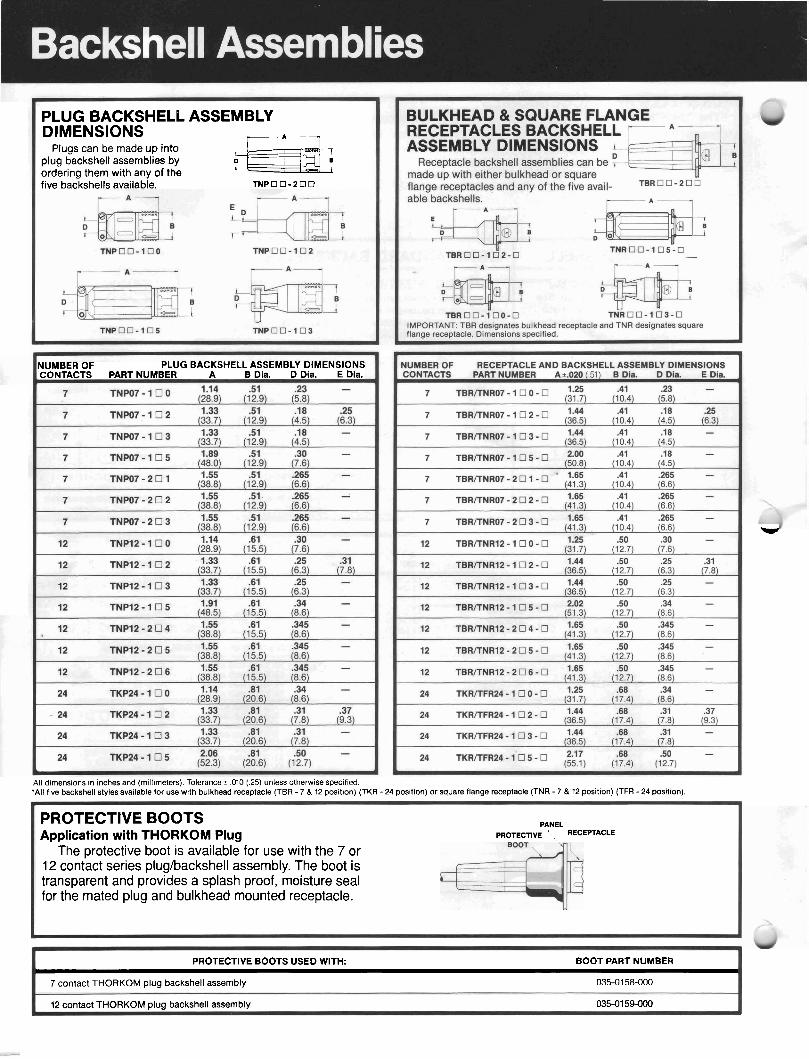
PLUG BACKSHELL ASSEMBLY DIMENSIONS -A-
Plugs can be made up into plug backshell assemblies by ordering them with any of the
;-&*: 7
five backshells available. T N P O O - 2 0 0
NUMBER OF PLUG BACKSHELL ASSEMBLY DIMENSIONS CONTACTS PART NUMBER A B Dia. D Dia. E Dia.
All dimensions in inches and (millimeter?.). Tolerance r ,010 (.25) unless otherwise specified. 'All five backshell styles available for use with bulkhead receptacle (TBR - 7 & 12 position) (TKR
*
- 24 position) or square flange receptacle (TNR - 7 & 12 position) (TFR - 24 position).
PROTECTIVE BOOTS PANEL
Application with THORKOM Plug PROTECTIVE RECEPTACLE
The protective boot IS available for use with the 7 or 12 contact series plug/backshell assembly. The boot is transparent and prov~des a splash proof, moisture seal for the mated plug and bulkhead mounted receptacle.
PROTECTIVE BOOTS USED WITH: BOOT PART NUMBER r I
7 contact THORKOM plug backshell assembly 035-01 58-000
12 contact THORKOM plug backshell assembly 035-01 54000

L
CONTACT INSERTIONIEXTRACTION TOOLS
=&%--- e;C-
T1E-100 GREEN (115-0147-000) RED (115-0150-000) BLUE (115-0392-000) F Handle contains 3 Tips lnsenlon (from rear) Socket Conlact Extractor Pln Contract Extractor
Both Pin & Socket (from fronl of plug) (from front of receptacle)
h
CRIMP TOOLS
T-422 CRIMP TOOL Crlmps contact wlre slzes 22 & 24 AWG only
, TC-100 CRIMP TOOL Crlmps 22 thru 26 AWG wlre slzes
I
-
HAND WIRE STRIPPER
HWS-100 Slrlps wlre gauges 17 thru 28 AWG lo precise length every tlme
v
ASSEMBLY INSTRUCTIONS
A. Crimping (Use wire gauges 22 thru 26 AWG.) 1. Strip insulation from wire ex-
posing conductor .200" + .015". 2. lnsert contact into crimping tool
positioner and insert stripped end of wire into contact crimp barrel.
3. Close crimp tool until tool re- leases-remove contact and wire assembly.
B. Contact Insertion STEP I
Step I. Place insulator for contact inser- tion onto proper mating connector on fixture.
Step 11. Feed wire bundle thru the back- shell (if one is used). lnsert con- tacts by hand into the back of the insulator.
Step Ill. Fit insertion tip between end of SUGGESTED CONTACT INSERTION FIXTURE
wire insulator and end of crimp barrel. Push contact into insulator until contact snaps into locked position. Slide backshell forward and thread it into the insulator.