THOR USER’S MANUAL: TUTORIAL...
67
THOR USER’S MANUAL: TUTORIAL AND COMIWANDS Robert Alverson Tom Blank Kiyoung Choi Sun Young Hwang Arturo Salz Larry Soule Thomas Rokicki Technical Report: CSL-TR-88-348 January 1988 This work was supported by Defense Advanced Research Projects Agency, Contract No.MDA903-83-C-0335.
Transcript of THOR USER’S MANUAL: TUTORIAL...

THOR USER’S MANUAL:TUTORIAL AND COMIWANDS
Robert AlversonTom BlankKiyoung ChoiSun Young HwangArturo SalzLarry SouleThomas Rokicki
Technical Report: CSL-TR-88-348
January 1988
This work was supported by Defense Advanced Research Projects Agency,Contract No.MDA903-83-C-0335.


THOR USER’S MANUAL: TUTORIAL AND COMMANDS
Robert Alverson, Tom Blank, Kiyoung Choi, Sun Young Hwang, Arturo Salz,Larry Soule, and Thomas Rokicki
Technical Report: CSL-TR-88-348
January 1088
Computer Systems LaboratoryDepartments of Electrical Engineering and Computer Science
Stanford UniversityStanford, CA 943054055
Abstract
THOR is a behavioral simulation environment intended for use with digital circuits ateither the gate, register transfer, or functional levels Models are written in the CHDLmodeling language (a hardware description language based on the W” programminglanguage). Network descriptions are written in the CSL language supporting hierarchical
network descriptions. Using interactive mode, batch mode or both combined, a variety
of commands are available to control execution. Simulation output can be viewed in
tabular format or in waveforms. A library of components and a toolbox for building
simulation models are also provided. Other tools include CSLIM, used to generate
boolean equations directly from THOR models and an interface to other simulators (e.g.RSIM and a physical chip tester) so that two simulations can be run concurrently
verifying equivalent operation.
This technical report is part one of two parts and is formatted similar to UNIX manuals.
Part one contains the THOR tutorial and all the commands associated with THOR.Part two contains descriptions of the general purpose functions used in models, the parts
library including many TTL components, and the logic analyzer model. For first timeusers, the tutorial in the first report is the best starting place; additionally, the THOR(l)man page is the root of the documentation tree in that all other documents arereferenced there.
Key Words and Phrases: behavioral simulation, functional model, hierarchical
network description

Copyright 1988bY
Robert AlversonTom Blank
Kiyoung ChoiSun Young Hwang
Arturo SalzLarry Soule
Thomas Rokicki
ACKNOVVLEDGMENTS
Many acknowledgments are necessary since THOR’s heritage is long. Specifically, theevolution started from the CSIM program at the University of Colorado, where ProfessorMike Lightner, and Henry and Beverly Vellandi created the core system anddocumentation. At Stanford, we’ve rewritten and greatly extended the original workthrough the labors of Robert Alverson, Professor Tom Blank, Kiyoung Choi, Dr. SunYoung Hwang, Arturo Salz, Larry Soule and Thomas Rokicki.


DISTRIBUTION TAPE
A copy of the distribution tape can be obtained by writing or calling:
Software Distribution CenterOffice of Technology Licensing
Stanford University350 Cambridge Avenue
Palo Alto, CA 94306
Telephone: (415) 723-0651

1. Introduction
This tutorial is intended for the first time user of the THOR simulation tools. THOR runs under theUNIX operating system. The tutorial assumes that the user is familiar with basic concepts of UNIX,such as directories, files, environment variables, and input/output redirection. Further, the user shouldunderstand the C programming language.
The goal of this tutorial is to help the new THOR user understand the following:
- What is functional simulation?- How are hardware designs described?- How are input stimuli vectors specified?- How are signals in a circuit monitored?- How is the simulator run in batch and interactive modes?- How can a circuit model be created and incorporated into the simulator?- How to interface to other simulators?
1.1. Historical Perspective
THOR is a functional simulator written by the VLSI/CAD Group at Stanford University to aidhardware designers to verify their designs. It is based on the CSIM simulator, a conventional event-driven functional/behavioral simulator developed by the VLSI/CAD Group of the University ofColorado, Boulder. THOR was developed to provide hardware designers with an interactive, efficientsimulation tool.
1.2. Definitions and Conventions
Some terms are used consistently in this tutorial:
- Element means an instantiation of a primitive functional model in a circuit, regardless of its level ofdescription. It can be a simple logic gate, whose functional behavior is provided by the system, or amore complex functional block, whose model is provided either by the system or by the user.
- Pin or port is a connection point to an element, through which a logic signal flows in and out of theelement.
- Structure or topology of a circuit is used to represent the interconnection of elements. This can bevisualized as a block diagram in which each block is an element and the lines connecting the blocksdetermine the interconnections.
- Nodes or nets are commonly used to refer to the interconnections.- Behavior means the response of an element to input stimuli. Behavior can be described for both an
element and a network of elements. For each element, the output is simply a function of its inputsandlcr its state variables. The mapping of the inputs and state variables to the outputs is Mined asthe behavior of the element. The behavior of a network is the response to the stimuli of all the ele-ments taken as a whole. The response is determined by a combination of each element’s behaviorand the interaction with other elements.
Throughout this tutorial, the following conventions are used:
- ‘5” indicates a prompt displayed on the CRT screen.

- Any terms that appear in a square bracket “[I” are optional.- Terms in a curly bracket “{}” are selectively used, i.e., {alb} means a or b.
2. Overview of THOR
This section describes the basic concepts of functional simulation, and the operation of the THORsimulator.
2.1. Why Use and What is a Functional Simulator?
When a hardware design is newly developed, its function needs to be verified. One way to verify theoperation of the circuit is to build the actual hardware or prototype, exercise the test vectors and moni-tor the results. This is costly and time consuming. If we can verify the functions of the design in somefaster and cheaper way before the prototype is built, the debug cycle time and cost will be significantlyreduced. Functional simulation is one of the most effective methods of design verification. The cost offunctional simulation is much less than that of hardware breadboarding. It is easy to prepare inputstimuli for functional simulation and to debug and modify the designs. Moreover, the components thatare not available at the time of design can be simulated by correctly modeling them.
A functional simulator is a tool for verifying a hardware design by exercising it on a computer. Usu-ally, the hardware descriptions are supplied to the simulator with the description of input stimuli, thenthe simulator exercises it and gives the result.
2.2. What is THOR?
THOR is a mixed level event-driven simulator with which one can simulate hardware at the behaviorallevel, register transfer level, and/or gate level. It provides all the features required for functional simu-lation, including generation of input stimuli, monitoring of output results, modeling capability, andinteractive simulation control.
THOR also provides an interface to a switch-level simulator, RSIM, and a physical tester.
In the THOR system, internal network states are represented by four values: 0 (logical Low), 1 (logicalHigh), U (Undefined), and Z (Floating or High Impedance).
2.3. Operation of THOR
To simulate a hardware &sign, the user should first prepare a description of the hardware, input stimuli(test vectors), and information on where and how to monitor the simulation results. Then, the informa-tion is linked with libraries by the THOR system to generate an executable simulator by using the gen-sim command. Figure 1 shows the general view of the THOR simulator. The executable simulatorgenerated by the gensim command, can be run without interaction with users (batch mode) or can becontrolled by the user with commands given interactively or through a command file (interactive mode).The detailed description of those commands can be found in section 6.
2.4. Input Components to THOR System
As mentioned in the previous section, the user should supply the circuit description, input stimuli, andmonitor information to the THOR simulator. The circuit description consists of the models of circuitelements and their interconnections. Input stimuli and monitors are usually modeled as circuit elementscalled generator elements and monitor elements, respectively.

+ -------- +hardware description I Iwith input stimuli ---3 1 Iand nxmi tor I I
I Xl-KR I ---+ s i m u l a t o rI I I
l i b r a r i e s --+ I I I simulation andI I I pos t -process ing+ -------- +
1resul t s
Figure 1. General view of THOR simulator
2.4.1. Functional Model
A model describes the behavior of a primitive functional element. Each model can be used in morethan one place in the circuit. In the THOR system, models are written in a language called CHDL (CHardware Description Language). CHDL is based on the C programming language with added featuresfor hardware modeling. Besides the behavior of a functional element, other descriptions can beincluded in a functional model, such as port descriptions and initialization routines. Generator andmonitor elements can also be modeled in the same way as other functional elements.
Many models are provided in the THOR library, which include generic logic gates (NAND, OR, XORgates, etc.), various TTL parts, generator elements (Up/Down Binary Counters, Clocks with variableperiod and phases, etc.), and monitor elements.
2.4.2. Net List
In the THOR system, a component-oriented net list language, called CSL, is used to specify the con-nections where each statement in the net list specifies an element and the connections of its ports tonodes in the circuit.
Each functional element has various attributes and CSL allows each of these attributes to be specifiedfor each element. CSL also allows hierarchical description, where a group of elements can be definedand treated as an entity called a subnetwork. Each statement in the net list specifies a model (or sub-network) name, instance name, all the input, output, and biput connections, and instance-specific valuesfor each element such as output delays and initial values.
2.5. Interfaces
Other design tools can be accessed in the THOR simulation environment through procedural interfaces.This section describes those interfaces to other utilities and &sign tools.
2.5.1. Simview
Simview takes the simulator outputs generated by the THOR simulator, and generates user readable
4

data in tabular format.
2.5.2. Analyzer, Banalyzer
Analyzer is a monitorgraphic display.
program which converts the data generated by the THOR simulator into a
Banalyzer is a monitor which writes the states of its inputs to a file so that they can be viewedgraphic forms using the graphic analyzer (program called ana) or in a table format using aview.
later in
2.53. CSLIM
Some functional models can be written to automatically generate hardware implementations usingCSLIM. Though it is very hard to synthesize the hardware with arbitrary structures, hardware withregular structures, like PLAs can be synthesized with less difficulty. CSLIM takes a finite statemachine model written in a subset of the THOR modeling language, CHDL, and generates the PLAequations which can then be optimized using espresso.
2.5.4. Interface to RSIM and Physical Tester
As mentioned before, THOR supports the simulation of the circuits with abstraction levels from gatelevel to behavioral level. Even though it does not provide the features for switch level simulation, itprovides a procedural interface to a switch level simulator RSIM, so that the THOR functionalspecification can be used to verify a design at the switch level. Furthermore, verification can beextended to a physical chip tester.
3. Getting Started
In this section, more detailed descriptions are presented on how to simulate a hardware design using theTHOR simulator.
3.1. Preparing a Net List File
To simulate a hardware design, a net list file describing the top level interconnections of functional ele-ments must be presented to the simulator. Each constituent functional block can be a net list file or afunctional module whose behavior is written in CHDL.
Each statement in the net list file corresponds to a single element or a subnetwork, and is comprised ofvarious fields specifying the element attributes. The detailed descriptions of these attributes can befound in section 5.
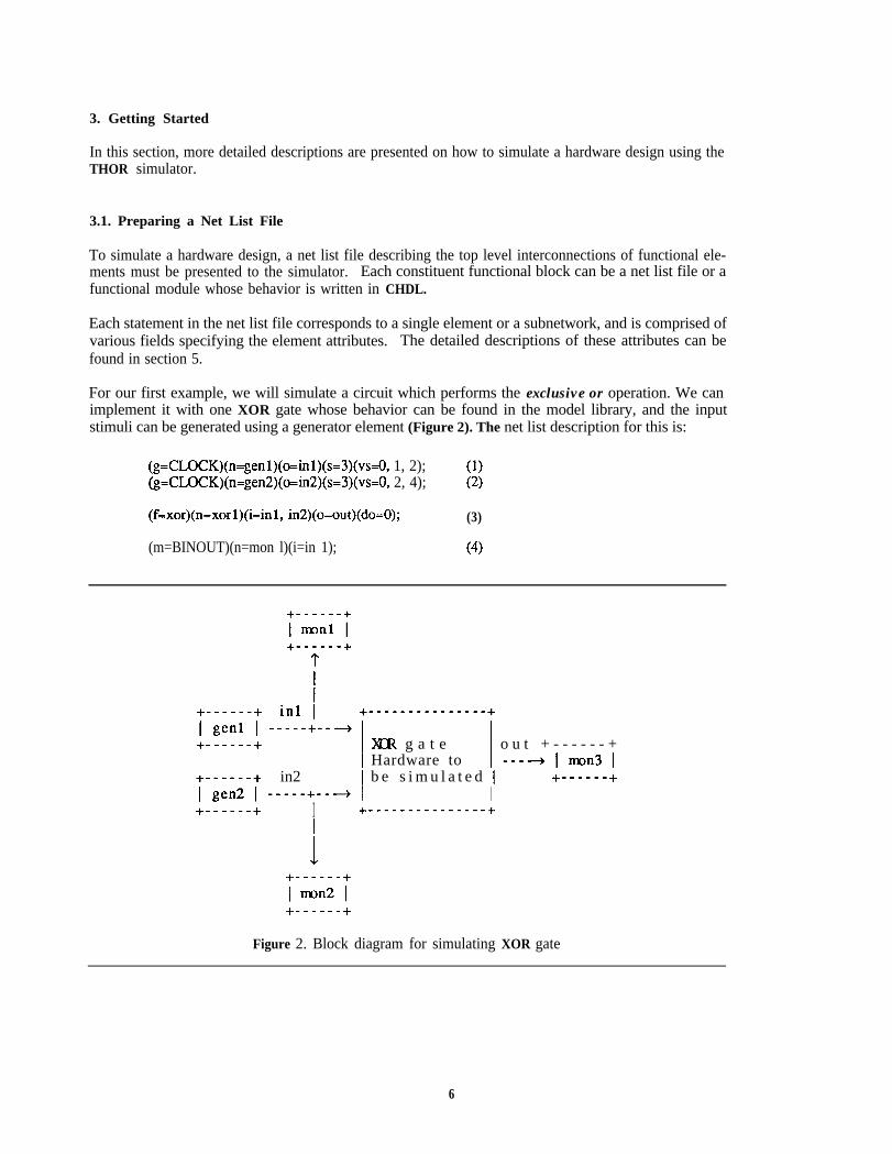
For our first example, we will simulate a circuit which performs the exclusive or operation. We canimplement it with one XOR gate whose behavior can be found in the model library, and the inputstimuli can be generated using a generator element (Figure 2). The net list description for this is:
(g=CLOCK)(n=genl)(o=inl)(s=3)(vs=O, 1, 2); (1)(g=CLOCK)(n=gen2)(o=in2)(s=3)(vs=O, 2, 4); (2)
(f=xor)(n=xorl)(i=inl, in2)(o=out)(do=O); (3)
(m=BINOUT)(n=mon l)(i=in 1); (4)
in1 i;-,;-;-; -----+----) y-------------y
+-m---e+ 1 )(cR g a t e I o u t + - - - - - - +I Hardware to I ---4 1 mon3 I
--SW-+ in2 I b e s i m u l a t e d IT-gen2 I -----+---+ I
+------+I+------+ I +---------------+
Figure 2. Block diagram for simulating XOR gate
6
(m=BINOUT)(n=mon2)(i=in2); (5)(m=BINOUT)(n=mon3)(i=out); - 0%
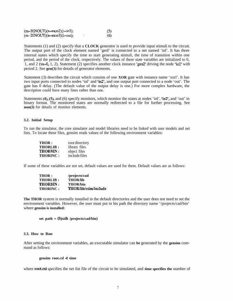
Statements (1) and (2) specify that a CLOCK generator is used to provide input stimuli to the circuit.The output port of the clock element named ‘genl’ is connected to a net named ‘inl’. It has threeinternal states which specify the time to start generating stimuli, the time of transition within oneperiod, and the period of the clock, respectively. The values of these state variables are initialized to 0,1, and 2 (vs=O, 1, 2). Statement (2) specifies another clock instance ‘gen2’ driving the node ‘in2’ withperiod 2. See gen(3) for details of generator elements.
Statement (3) describes the circuit which consists of one XOR gate with instance name ‘xorl’. It hastwo input ports connected to nodes ‘inl’ and ‘in2’, and one output port connected to a node ‘out’. Thegate has 0 delay. (The default value of the output delay is one.) For more complex hardware, thedescription could have many lines rather than one.
Statements (4), (5), and (6) specify monitors, which monitor the states at nodes ‘inl’, ‘in2’, and ‘out’ inbinary format. The monitored states are normally redirected to a file for further processing. Seemon(3) for details of monitor elements.
3.2. Initial Setup
To run the simulator, the core simulator and model libraries need to be linked with user models and netlists. To locate these files, gensim reads values of the following environment variables:
THOR : root directoryTHORLIB : library filesTHORBIN : object filesTHORINC : include files
If some of these variables are not set, default values are used for them. Default values are as follows:
THOR :THORLIB :THORBIN :THORINC :
/projects/cadTHOR/libTHOR/binTHOR/lib/csim/include
The THOR system is normally installed in the default directories and the user does not need to set theenvironment variables. However, the user must put in his path the directory name ‘/projects/cad/bin’where gensim is installed:
set path = @path /projects/cad/bin)
3.3. How to Run
After setting the environment variables, an executable simulator can be generated by the gensim com-mand as follows:
gensim root.csl 4 time
where rooks1 specifies the net list file of the circuit to be simulated, and time specifies the number of
7

simulation time steps. The name of the net list file should be extended with .csl. The gensim com-mand will generate an executable file root.exe, and the monitored network states are written into thefile root.oui, if not redirected.
Following is the sample simulation session for the circuit described in section 3.1. Here, xor.csl is thefilename of the net list. We want to run the simulator for 3 time steps.
> gensim x0r.d 4 3
.xor.exe -t 3 > xor.out> cat xor.out30 mon3 0Omon2 10 monl 11 mon3 11 monl 02mon202 monl 13 mon3 03 monl 0
Without any processing, the result is difficult to read. The command simview does some processing onthe result to make it much easier to read.
> simview xor.outTHOR OUTPUT
T i m e u n i t sI mon31 1 mon2I I I monlI I I I0 0 1 11 1 1 02 1 0 13 0 0 0
The simulation can be done interactively by using the option 4 to the gensim command. If the execut-able simulator has already been generated, the -i option can be applied when the simulator is executed:
> xor.exe 4 > xor.outthor $ : O> enable in1 in2 outthor $ : O> step(out 0)(in2 1)(in1 1)thor $ : l> step(out 1)(in2 1)(in1 0)thor $ : 2> step
8

(out 1)(in2 0)(in1 1)thor $ : 3> step(out 0)(in2 0)(in1 0)thor $ : 4> exit>
The enable command displays the values of the nodes given as its arguments whenever the simulationstops. The step command executes the simulation for one time step. More explanations on interactivemode will be done in section 6.
3.4. Summary
Following is the summarized procedure of a simulation run, assuming that all the models are suppliedfrom the library.
1) Create a net list file: foobard
2) gensim foobard -t 3
3) simview foobar.out
4. Writing Models
In order for hardware designers to simulate the behavior of a hardware function, the functionality of thehardware must first be modeled. The basic concepts needed to create a model using the THOR model-ing language and an example of a basic model are described in this section.
4.1. THOR Modeling Language, CHDL
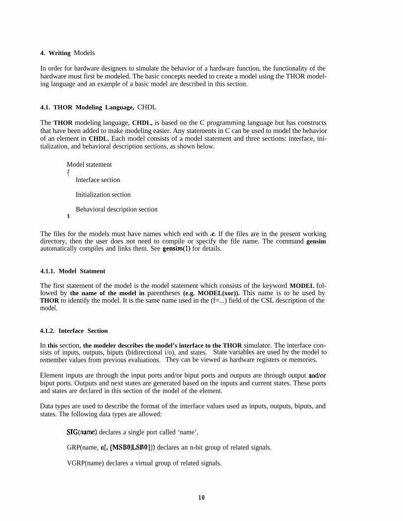
The THOR modeling language, CHDL, is based on the C programming language but has constructsthat have been added to make modeling easier. Any statements in C can be used to model the behaviorof an element in CHDL. Each model consists of a model statement and three sections: interface, ini-tialization, and behavioral description sections, as shown below.
Model statementIL
Interface section
Initialization section
Behavioral description section
The files for the models must have names which end with .c. If the files are in the present workingdirectory, then the user does not need to compile or specify the file name. The command gensimautomatically compiles and links them. See gensim(1) for details.
4.1.1. Model Statment
The first statement of the model is the model statement which consists of the keyword MODEL fol-lowed by the name of the model in parentheses (e.g. MODEL(xor)). This name is to be used byTHOR to identify the model. It is the same name used in the (f=...) field of the CSL description of themodel.
4.1.2. Interface Section
In this section, the modeler describes the model’s interface to the THOR simulator. The interface con-sists of inputs, outputs, biputs (bidirectional i/o), and states. State variables are used by the model toremember values from previous evaluations. They can be viewed as hardware registers or memories.
Element inputs are through the input ports and/or biput ports and outputs are through output and/orbiput ports. Outputs and next states are generated based on the inputs and current states. These portsand states are declared in this section of the model of the element.
Data types are used to describe the format of the interface values used as inputs, outputs, biputs, andstates. The following data types are allowed:
SIG(name) declares a single port called ‘name’.
GRP(name, n[, {MSBOILSBO}]) declares an n-bit group of related signals.
VGRP(name) declares a virtual group of related signals.
10
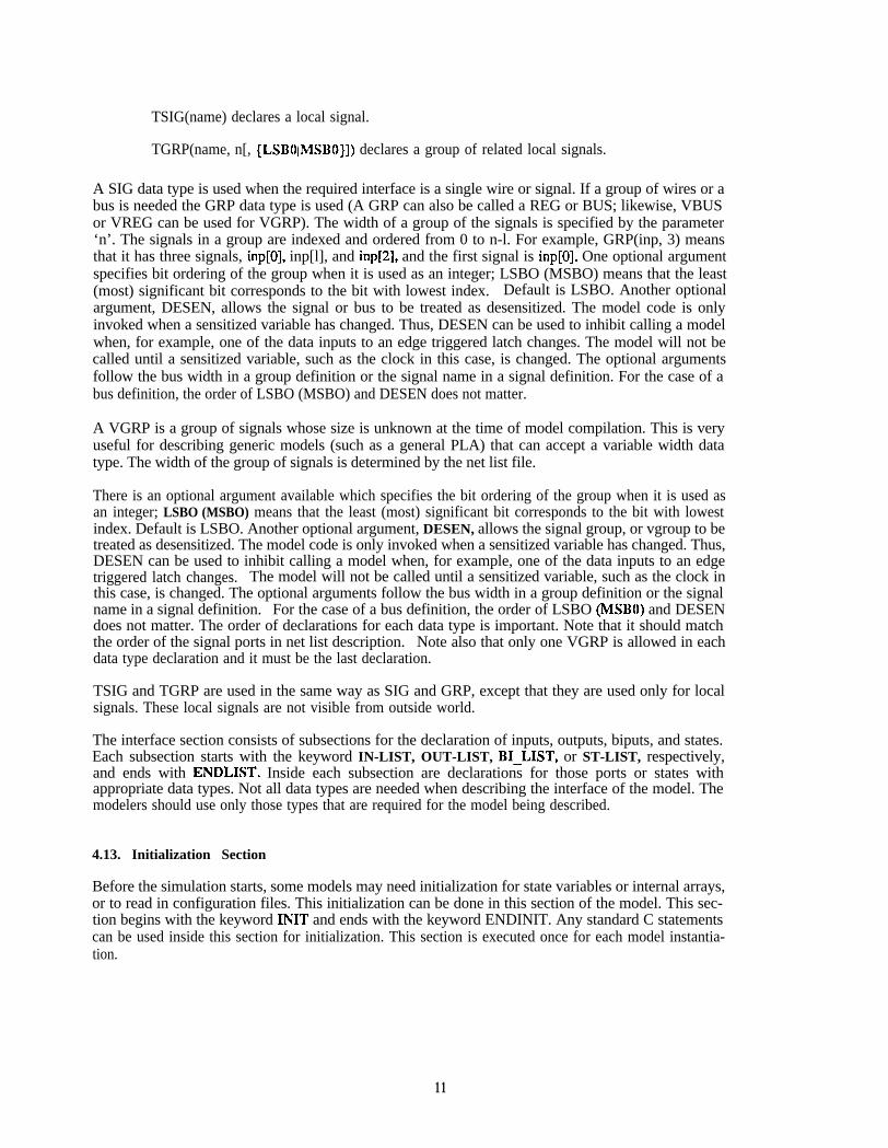
TSIG(name) declares a local signal.
TGRP(name, n[, {LSBOIMSBO}]) declares a group of related local signals.
A SIG data type is used when the required interface is a single wire or signal. If a group of wires or abus is needed the GRP data type is used (A GRP can also be called a REG or BUS; likewise, VBUSor VREG can be used for VGRP). The width of a group of the signals is specified by the parameter‘n’. The signals in a group are indexed and ordered from 0 to n-l. For example, GRP(inp, 3) meansthat it has three signals, inp[O], inp[l], and inp[2], and the first signal is inp[O]. One optional argumentspecifies bit ordering of the group when it is used as an integer; LSBO (MSBO) means that the least(most) significant bit corresponds to the bit with lowest index. Default is LSBO. Another optionalargument, DESEN, allows the signal or bus to be treated as desensitized. The model code is onlyinvoked when a sensitized variable has changed. Thus, DESEN can be used to inhibit calling a modelwhen, for example, one of the data inputs to an edge triggered latch changes. The model will not becalled until a sensitized variable, such as the clock in this case, is changed. The optional argumentsfollow the bus width in a group definition or the signal name in a signal definition. For the case of abus definition, the order of LSBO (MSBO) and DESEN does not matter.
A VGRP is a group of signals whose size is unknown at the time of model compilation. This is veryuseful for describing generic models (such as a general PLA) that can accept a variable width datatype. The width of the group of signals is determined by the net list file.
There is an optional argument available which specifies the bit ordering of the group when it is used asan integer; LSBO (MSBO) means that the least (most) significant bit corresponds to the bit with lowestindex. Default is LSBO. Another optional argument, DESEN, allows the signal group, or vgroup to betreated as desensitized. The model code is only invoked when a sensitized variable has changed. Thus,DESEN can be used to inhibit calling a model when, for example, one of the data inputs to an edgetriggered latch changes. The model will not be called until a sensitized variable, such as the clock inthis case, is changed. The optional arguments follow the bus width in a group definition or the signalname in a signal definition. For the case of a bus definition, the order of LSBO (MSBO) and DESENdoes not matter. The order of declarations for each data type is important. Note that it should matchthe order of the signal ports in net list description. Note also that only one VGRP is allowed in eachdata type declaration and it must be the last declaration.
TSIG and TGRP are used in the same way as SIG and GRP, except that they are used only for localsignals. These local signals are not visible from outside world.
The interface section consists of subsections for the declaration of inputs, outputs, biputs, and states.Each subsection starts with the keyword IN-LIST, OUT-LIST, BI-LIST, or ST-LIST, respectively,and ends with ENDLIST. Inside each subsection are declarations for those ports or states withappropriate data types. Not all data types are needed when describing the interface of the model. Themodelers should use only those types that are required for the model being described.
4.13. Initialization Section
Before the simulation starts, some models may need initialization for state variables or internal arrays,or to read in configuration files. This initialization can be done in this section of the model. This sec-tion begins with the keyword INIT and ends with the keyword ENDINIT. Any standard C statementscan be used inside this section for initialization. This section is executed once for each model instantia-tion.
11

4.1.4. Behavioral Description Section
The behavioral description section is the main body of the model containing the algorithms or descrip-tions that the modeler is trying to construct.. This section of the model is executed whenever an inputor biput changes. The code should generate new outputs, biputs, and state variables based on its currentstate and inputs. It comes after interface and initialization sections. All standard C statements areallowed. However, to describe the behavior of the hardware efficiently, constructs are needed thatallow data to be moved and changed when the model is evaluated. Capabilities that are not providedby the C programming language, such as data formatting and conversions are provided to the modeler.A list of functions available can be found in the THOR(l) man page, and the detailed descriptions ofeach function can also be found in its own man page.
The final statement before exiting the behavioral description section must be EXITMOD(value); anon-zero ‘value’ indicates an error. Any number of EXITMOD(value) statements can be used.
4.2. Examples
4.2.1. Example 1
Here is a basic model of an exclusive or gate.
/***I
two-input xor gate
MODEL(xor){/* Interface section */
IN LIST-SIG(in0);SIG(in1);
ENDLIST;
OUT LIST%G(out);
ENDLIST;
/* Behavioral description section */int i; /* Declaration of a variable for internal use */
out = ZERO;
if(((inO == ONE) && (in1 == ZERO)) II ((in0 == ZERO) && (in1 == ONE)))out = ONE;
EXITMOD(0);
The xor gate has no biput ports and states so no declarations are needed for them in this model. It hasno initialization section, either.
12
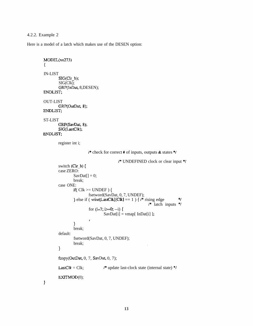
4.2.2. Example 2
Here is a model of a latch which makes use of the DESEN option:
MODEL(xx273)
IN-LISTSIG(Clr-b);SIG(Clk);GRP(InDat, 8,DESEN);
ENDLIST;
OUT-LISTGRP(OutDat,
ENDLIST;
ST-LISTGRP(SavDat,SIG(LastClk);
ENDLIST;
register int i;
8);
8);
/* check for correct # of inputs, outputs & states */
switch (Clr-b) {case ZERO:
SavDat[] = 0;break;
case ONE:
/* UNDEFINED clock or clear input */
if( Clk >= UNDEF ) {fsetword(SavDat, 0, 7, UNDEF);
} else if ( vriselLastClk][Clk] == 1 ) { /* rising edge *//* latch inputs */
for (i=7; i>=O; --i) {SavDat[i] = vmap[ InDat[i] 1;
1 ’break;
default:fsetword(SavDat, 0, 7, UNDEF);break; ,
I
fcopy(OutDat, 0, 7, SavDat, 0, 7);
LastClk = Clk; /* update last-clock state (internal state) */
EXITMOD( 0);
13
4.2.3. Example 3
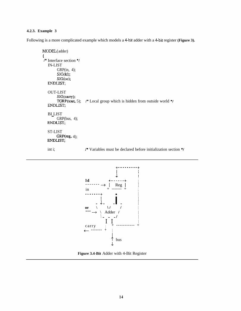
Following is a more complicated example which models a 4-bit adder with a 4-bit register (Figure 3).
MODEL( adder)1I* Interface section *I
IN-LISTGRP(in, 4);SIG(ld);SIG@);
ENDLIST;
OUT-LISTSWcarry);TGRF’(tout, 5); I* Local group which is hidden from outside world */
ENDLIST;
BI LIST-GRP(bus, 4);
ENDLIST;
ST-LISTGRP@g, 4);
ENDLIST;
int i; I* Variables must be declared before initialization section *I
IIId ------+ I- - - - - - - + i- Reg 1 Iin + ------- + I------- +1 i i
I- - - - l
oe \ \I I I--- + \ Adder I I\ I- - - lI I I
carry I + ----------- ++- ------- + I
c busL
Figure 3.4-Bit Adder with 4-Bit Register
14

/* Initialization section */INIT
reg[3:0] = 0; /* Initializes state variables */ENDINIT;
/* Behavioral description section */if(ld == ONE) reg[3:0] = bus[3:0];
tout[4:0] = in[3:0] + reg[3:0];
if(oe == ONE)bus[3:0] = tout[3:0];
elsefor(i = 0 ;i C= 3; i++) bus[i] = FLOAT;
carry = tout[4];
EXITMOD(0);
15

5. Net List Description
5.1. CSL Format
Net lists in the THOR system are described with the language CSL. This language describes how thevarious elements and subnetworks are connected together. Each CSL statement corresponds to a singleelement or a subnetwork. A CSL statment is comprised of various fields, each field specifying an attri-bute of an element. The element attributes and their associated field identifiers are shown in Table 1.Note that the three attributes (f=...), (g=...), and (m=...) are selectively used depending on the type of theelement and only one of the three can be used in each CSL statement.
For example, given a three input AND gate that has inputs connected to nodes named ‘a’, ‘b’, ‘c’ andan output connected to a node named ‘d’ and output delay 2. The CSL statement for this elementwould be:
(f=AND)(n=gatel)(i=a, b, c)(o=d)(do=2);
Note that each field is surrounded by a left and right parenthesis. Each field begins with a fieldidentifier, ‘f=‘, ‘n=‘, ‘i=‘, etc. Following the field identifier is information associated to each type offield or attribute.
Anything contained within ‘/*’ and ‘*/’ is ignored. Actually comments are limited to 2000 characters inlength due to limitations of lex. So, care should be taken when commenting out large parts of CSLfiles.
CSL supports subnetworks. A subnetwork is a group of elements that has a fixed topology and can bereferenced as a unit, once defined Subnetwork can be described in terms of other subnetworks. A
Attribute I Field
element type
instance nameinput portsoutput portsbidirectional portsinitial values
delays
number of states
1 (f=...) for functional element1 (g=...) for generator elementI (m=...) for monitor element1 (n=...)1 (i=...)1 (o=...)1 (b=...)I (vo=...) for output portsI (vb=...) for bidirectional ports1 (vs=...) for statesI (do=...) for output ports (default is 1)I (db=...) for bidirectional ports (default is 1)1 (s=...)
Table 1. Element attributes and associated field identifiers
16
subnetwork is defined using the following syntax:
(sub=...)(i=...)(o=...)(b=...){
CSL statements specifying the structure of the subnetwork.
To reference a subnetwork, the subnetwork type is used in the element type field.
AI1 the subnetwork descriptions can be written into one file with the upper level description. The usercan also create files for some or all of the subnetwork descriptions. Each file should have the samename as the subnetwork type with an extension ‘.csl’. In this case, the statement referencing the sub-network should also have the extension ‘.csl’ in its element type field (see the following example).
5.2. Example
For example, the description of xor logic in section 3.1 can be rewritten as follows:
(sub=xor)(i=inl, in2)(o=o3);{
(f=inv)(n=invl)(i=inl)(o=inlbar)(do=O);(f=inv)(n=inv2)(i=in2)(o=in2bar)(do=O);(f=and)(n=andl)(i=inlbar, in2)(o=ol)(do=O);(f=and)(n=and2)(i=inl, in2bar)(o=o2)(do=O);(f=or)(n=orl)(i=ol, o2)(o=o3)(do=O);
It can be referenced using:
(f=xor)(n=xorl)(i=a, b)(o=c);
and would be expanded to:
(f=inv)(n=xorl.invl)(i=a)(o=xorl.inlbar)(do=O);(f=inv)(n=xorl .inv2)(i=b)(o=xorl .in2bar)(do=O);(f=and)(n=xorl.andl)(i=xorl.inlbar, b)(o=xorl.ol)(do=O);(f=and)(n=xorl.and2)(i=a, xorl .in2bar)(o=xorl .o2)(do=O);(f=or)(n=xorl.orl)(i=xorl.ol, xorl.o2)(o=c)(do=O);
The names of internal nodes and element names have been expanded by concatenating the instancename of the subnetwork.
If the subnetwork description is contained in a separate file, the file name should be ‘xorcsl and itshould be referenced as follows:
(f=xor.csl)(n=xorl)(i=a, b)(o=c);
17

6. Interactive Mode
6.1. How to Enter the Interactive Mode
The THORoption.
simulator can be run interactively. To enter the interactive mode, run the simulator with -i
root.exe -i[filename] [-q] [-I] [-cl
In the interactive mode of operation, other options are available. If filename is given after -i option, thefile is read as a command file and executed. If -q option is given, quiet mode is set and nothing willbe displayed while the command file is executed. Otherwise, all the command lines and their results aredisplayed as if the commands were given from keyboard interactively. If -1 option is given, a log filewith an extension of Jog is generated. If -c option is given, a commandjfile with an extension of .cmdis generated. Following is an example:
> xor.exe 4 test.cmd -I -c
Initially, the command file test.cmd is read in and each command in the file is executed one by one. Ifthe simulator encounters an exit (or quit) command while reading the command file, it exits. Other-wise, after all the commands from the file have been executed, a prompt is displayed for interactivecommands from the user. All the commands supplied from the command file and from the user directlyare written into the file named xor.cmd. All the lines displayed on the screen are stored into the filexor.log.
After entering the interactive mode of simulation, the system writes a prompt on the terminal. Theprompt includes the current directory path and current simulation time maintained by the simulator.Network hierarchy is considered similar to the file system hierarchy. A file can be considered as anelement, or a node, while a directory can be considered as a subnetwork. To confine the range of thescope to a particular subnet, the change command can be used.
The user can respond to the prompt by entering a command followed by option fields. Unambiguousabbreviations are accepted. For example, st and ste are acceptable as the command step. The wild-card characters * and ? are allowed in arguments. For the detailed description of each interactive com-mand, see intTHOR(l).
6.2. Example Session of Interactive Mode Simulation
Following is a gate level description of exclusive or logic mentioned in section 5.2.:
/* Top level CSL description *//* Filename is xortest.csl */(g=CLOCK)(n=genl)(o=inl)(s=3)(vs=O, 1, 2);(g=CLOCK)(n=gen2)(o=in2)(s=3)(vs=O, 2, 4);(f=xor.csl)(n=xorl)(i=inl, in2)(o=out);
/* CSL description of xor */(sub=xor)(i=inl, in2)(o=o3)
L (f=inv)(n=invl)(i=inl)(o=inlbar)(do=O);
18

(f=inv)(n=inv2)(i=in2)(o=in2bar)(do=O);(f=and)(n=andl)(i=inlbar, in2)(o=ol)(do=O);(f=and)(n=and2)(i=inl, in2bar)(o=o2)(do=O);(f=or)(n=orl)(i=ol, o2)(o=o3)(do=O);
Following is an interactive simulation session of the above example:
> xortest.exe 4
thor $ : O> ena in1 in2 out . . . ena is an abbreviation of enable.
thor $ : O> dump(out U)(in2 U)(in1 U)
. . . Dumps all the enabled nodes.. . . All the nodes are initialized to
UNDEF by default.
thor $ : O> st(out 0)(in2 1)(in1 1)
. . . Steps one time period.. . . Dumps all the enabled nodes and
elements when the simulation stops.
thor $ : 1~ cha xorl . . . Working directory is changed to ‘$.xorl’.
thor $.xorl : l> exa invl.Element xorl .inv 1 :
Input pins :
. . . Examine the element ‘invl’.
(inputgin[O-O](indat[O-01) 1)Output pins :
. . . ‘indat’ is the name of input pin#O. It has value 1.
(outputgin[O-O](outdat[O-01) 0)
thor $.xorl : l> corm inv2. . . . Shows the connectivity of the element ‘inv2’.input nodes to element xorl.inv2:
inputgin[O](indat) --- node (in2 1). . . Input pin#O is connected to the node ‘in2’ whose value is 1.
output nodes from element xorl.inv2:(outputgin[O](outdat) 0) --- node (xorl.irQbar 0)
thor $.xorl : l> corm in2bar . . . Shows the connectivity of the node ‘in2bar’.inputs to node xorl.in2bar:
xorl.inv2 (outputgin[O](outdat) 0). . . The node is driven by the output pin##O of element
‘xorl.inv2’ with value 0.pins driven by node xorl .in2bar with value 0:
xorl.and2 inputgin[l](indat[l])
thor $.xorl : l> st(out 1)(in2 1)(in1 0)
thor $.xorl : 2> cha n
thor $ : 2> bre (out 0)
. . . Working directory is changed to upper level.
. . . Sets break point.
19

thor $ : 2> bre[41 (out 0)
thor $ : 2> go +5break at 3: [43 (out 0)(out 0)(in2 0)(in1 0)
thor $ : 4> cle *
thor $ : 4> bre
thor $ : 4> mark
thor $ : 4> go 7(out 0)(in20)(in1 0)thor $ : 8> restart
thor $ : 4~ sho max-time(max-time 1000)
thor $ : 4> set (max-time 7)
. . . Shows break points set.
thor $ : 4> go(out 0)(in2 0)(in1 0)
thor $ : 8> exit
. . . Simulates 5 steps.. . . Break point(node ‘out’ has value 0)
. . . Clears all the break points set..
. . . Marks current simulation time which is 4.
..* Restarts from marked time 4.
. . . Shows the value of max-time.
. . . Simulates to max-time.
. . . Exits.
>
20

7. Tips and Common Errors
7.1. Self Scheduling
During simulation, each element is only evaluated whenever one of its input or biput ports changes,The states and outputs of the element are determined depending on its behavior for the values of itsinput or biput ports. However, there are elements whose internal states or output values change withoutany stimuli from external world. For example, the generator element, CLOCK, changes its outputvalue periodically, though it has no input ports. To simulate such an element correctly, it is necessaryfor the model to be able to schedule itself for future evaluation. This can be done by calling the pro-cedure self-sched in the behavioral description section of the model. Following is a simplified modelof the generator, CLOCK, which shows the usage of self-schedule.
/* CLOCK0* Clock driver function* - uses 2 parameters [Ttrans,Tperiod].* - and always starts from time 0.*/
MODEL(CLOCK)
OUT LISTSIG(&);
ENDLIST;
ST-LISTSIG(Ttrans);SIG(Tperiod);
ENDLIST;
/* we must be either at the end of a clock cycle or* at the duty cycle transition. Schedule both* evaluations at clock cycle end*/
if(current-time % Tperiod == 0) /* at end of clock cycle, or at start */C
/* sched for duty cycle transition */self-sched(Ttrans, SELFO);/* sched for period */self-sched(Tperiod, SELFO);
,
elk = (current-time % Tperiod) < Ttrans ? ONE : ZERO;
EXITMOD(
The external variable current-time keeps the current simulation time. The procedure call toself sched(Ttrans, SELFO) schedules the evaluation of the element at (current time + Ttrans) withprioTity SELFO. The priority SELF0 indicates that the element has the highest psority and thus shouldbe evaluated before any other elements.
Similarly, the function self-unsched removes the scheduled element already scheduled for future
21
evaluation from the event queue.
7.2. Getting Instance Names from within a Model
When debugging a hardware design or its behavioral model, it is sometimes useful to have, in a model,its instance names defined by its caller or the node names connected to the element.
When an element is evaluated by executing its behavioral model, the procedures mname() andiobname(type, index) returns the pointer to the element’s name (model’s instance name) and nodename connected to the specified port of the element, respectively.
Consider the following statement in a net list file.
(f=xor)(n=xorl)(i=inl, in2)(o=out);
The function mname() in the ‘xor’ model returns its instance name ‘xorl’, and the functioniobname(CINPUT, 2) returns the node name connected to the second port of the element, ‘in2’.
7.3. Tquote
The user can simulate his or her design by applying the input stimuli of very regular patterns using thegenerator elements such as CLOCK or COUNT. However, arbitrary patterns are sometimes necessaryto simulate designs. In THOR, the user can create arbitrary patterns using a generator element calledTquote. The generator Tquote reads in the input stimuli from a file created by the user. Following isan example CSL description.
(g=Tquote)(n=input.stim)(o=stiml, stinQ)(s=3)(vs=2);
where ‘input.stim’ specifies the name of the stimulus file provided by the user. Tquote has three inter-nal states: the first one is the period and the other two are for internal use and need not be specified bythe user, In the above example, the values of its outports ‘stiml ’ and ‘stim2’ are read in from thestimulus file ‘input.stim’ every two simulation time steps.
Each statement in the stimulus file begins with either a T or a *. The * mark designates a commentthat terminates by a ;. The line starting with T character specifies an input vector which is enclosed ina pair of quotes. Each bit of its input vector can have one of the following values: 0, 1, u (U), or z(2). Note that the number of values inside the quotes must match the number of the output ports of theelement specified in the CSL statement. A stimulus file for the above example looks like:
* This is a comment line;T’OO’T’Ol’ T’Oz’ . . .T’UZ’
At time 0, the ports ‘stiml’ and ‘stim2’ get values 0 and 0, respectively. Then, after 2 time steps, theyget 0 and 1, and so on.
7.4. Zero Delay Problems
It is sometimes very convenient to simulate the hardware with all the output delays of each element set
22

to zero (zero delay simulation). Especially for combinational logic with different numbers of elementsfrom one input port to one output port, the results of zero delay simulation are much easier to examine.
For efficient simulation with zero delay models, it is required that the circuit be ordered topologically.Let’s consider the circuit in Figure 4. In zero delay simulation, when there occurs an event at node‘n2’, alI of the elements ‘a’, ‘b’, ‘c’, and ‘d’ will be evaluated. Due to these evaluations, new eventscan be created at nodes ‘n3’, ‘n4’, and ‘n5’. Thus, depending on the order of evaluations, the elements‘b’, ‘c’, and ‘d’ may be re-evaluated. This, in turn, makes the elements ‘c’ and ‘d’ be re-evaluated, andfinally the element ‘d’ should be re-evaluated again.
In THOR, there is no evaluation ordering. Therefore, the zero delay elements are repeatedly evaluateduntil the proper values are calculated (any zero delay elements in a loop may oscillate).
7.5. Handling Biputs
Handling biputs is somewhat tricky and the user should be careful when writing models having biputs.In THOR, if a node is driven by an element with an UNDEF signal, the signal value at the nodebecomes UNDEF and all the fanout elements (i.e., all the elements whose input or biput ports are con-nected to the node) are driven with the UNDEF signal. Assume that a biput port of an element is con-nected to a node. If the user writes the element’s model in such a way that it sets its biput port toUNDEF when it gets UNDEF through the biput port, the node will forever be stuck at UNDEF once itgets UNDEF. As an example, let’s consider modeling a pull up resistor. It is likely the user mightwrite the model as follows:
MODEL(Rpu)C
BI-LISTSIG(r);
ENDLIST;
switch( r ){
case UNDEF:r = UNDEF;break;
case FLOAT:r=ONE;break;
nl +---+ n 3 + - - - + n 4 +---+ n5 + - - - +S-B + 1 a I---+ 1 b I---+ I c I---+ I d I---+
+---+ +---+ +---+ +---++r ? T T
n2 I I I I--------+----------+----------+----------+
Figure 4. Example circuit showing the zero delay problem
23

default :r = FLOAT;break;
IEXITMOD(0);
I
Once the node connected to the biput port of the above model gets UNDEF, it would be stuck atUNDEF forever. This problem can be avoided as follows:
MODEL(Rpu){
BI-LISTSIG(r);
ENDLIST;
switch( r )C
case FLOAT:r=ONE;break;
&fault :r = FLOAT;break;
IEXITMOD(0);
7.6. Writing an Edge-Triggered Model
A level-sensitive element operates on the levels of its inputs, i.e. it generztes its outputs based on thelevels of its inputs. On the other hand, an edge-triggered element operates on the level transitions of itsinputs. Therefore, its model must store previous levels of its inputs to check level transitions. Follow-ing is an example model for a D-type positive-edge-triggered flip-flop:
MODEL(DFF)i
IN LIST-SIG(Clk);SIG(D);
ENDLIST;
OUT-LISTSIG(Q);SWQJ);
ENDLIST;
ST-LISTSIG(SavQ);SIG(LastClk);
ENDLIST;
if(Clk>=UNDEF) /* undefined clock input */
24

SavQ = UNDEF;
else if ( vrise&astClk][Clk] == 1 )SavQ = vmap[ D 1;
/* rising edge */
Q-b = vinv[ (Q = SavQ) 1;
LastClk = Clk;
EXITMOD(0);
/* store last Clk input */
25
8. Examples
8.1. A 4-Bit Adder, Functional Net List Description
Following is a CSL description of a 4-bit adder. It has two generator elements(COUNT) for thestimuli and two monitor elements, BINOUT and HEXOUT, to monitor the results. See gen(3) andmon(3) for details of generator and monitor elements.
(g=COUNT)(n=genl)(o=inl[3-O])(s= l)(vs=l);(g=COUNT)(n=gen2)(o=in2[3-O])(s=l)(vs=16);
(f=add4)(n=adder)(i=inl[O-31, in2[0-3])(o=sum[O-31, cout)(do=O, 0, 0, 0, 0);
The functional model of a 4-bit adder shown below can be used with the above CSL description.
/****************************************************************1
/* Functional model of a 4-bit adder */
MODEL(add4){
IN LIST-GRP(in1, 4);GRP(in2, 4);
ENDLIST;
OUT-LISTGRP(sum, 5);
ENDLIST;/* MSB is used for carry out */
/* if any input is not {ZERO, ONE}, make all outputs UNDEF */if(fckbin(in1, 3, 0) != PASSED I] fckbin(in2, 3, 0) != PASSED)1
fsetword(sum, 4, 0, UNDEF);EXITMOD(0);
I
sum[4:0] = in1[3:0] + in2[3:0];
EXITMOD(0);I/****************************************************************/
In this model, ‘fckbin’ is a library function which checks that the signals in a group have values in a set{ZERO, ONE}. ‘fsetword’ is also a library function which sets signal values to a specified value. Seefckbin(3) and fsetword(3) for details.
26

8.2. A 4-Bit Adder, Gate Level
This section shows how the 4-bit adder in section 8.1 can be described in gate level. Top level CSLdescription is almost the same:
(g=COUNT)(n=genl)(o=inl[3-O])(s= l)(vs=l);(g=COUNT)(n=gen2)(o=in2[3-O])(s=l)(vs=16);
(f=add4)(n=adder)(i=inl[O-31, in2[0-3])(o=sum[O-31, tout);
(m=BINOUT)(n=monl)(i=cout);(m=HEXOUT)(n=mon2)(i=sum[3-01);/****************************************************************/
Note that there is no delay information for the outputs of the ‘adder’ because it is not a primitive ele-ment but a subnetwork now. The CSL description of the subnetwork is as follows:
(sub=add4)( i=inl[O-31, in2[0-3])(o=sum[O-31, tout)C
(f=halfadd)(n=hadd)(i=inl [O], in2[O])(o=cO, sum[O]);(f=fulladd)(n=faddl)(i=inl[ 11, in2[ 11, cO)(o=cl, sum[ 11);(f=fulladd)(n=fadd2)(i=inl[2], in2[2], cl)(o=c2, sum[2]);(f=fulladd)(n=fadd3)(i=in1[3], in2[3], c2)(o=cout, sum[3]);
1/****************************************************************/
This subnetwork consists of four subnetworks: one half adder and three full adders as &scribed below.
(sub=halfadd)(i=inl, irQ)(o=cout, sum){
(f=xor)(n=xorl)(i=inl, in2)(o=sum)(do=O);
(f=and)(n=andl)(i=inl, in2)(o=cout)(do=O);I/****************************************************************/
(sub=fulladd)(i=inl, in2, cin)(o=cout, sum)i
(f=xor)(n=xorl)(i=inl, in2)(o=a)(do=O);(f=xor)(n=xor2)(i=a, cin)(o=sum)(do=O);
27
(f=and)(n=andl)(i=inl, in2)(o=b)(do=O);(f=and)(n=and2)(i=inl, cin)(o=c)(do=O);(f=and)(n=and3)(i=in2, cin)(o=d)(do=O);(f=or)(n=orl)(i=b, c)(o=e)(do=O);(f=or)(n=or2)(i=e, d)(o=cout)(do=O);
where all the functional elements are primitive elements and their models are in the library.
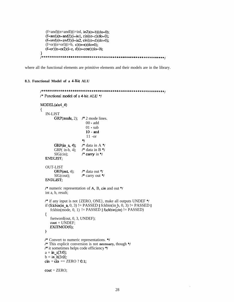
8.3. Functional Model of a 4-Bit ALU
MODEL(alu4-4)1
IN-LISTGRP(mode, 2); /* 2 mode lines.
00 - add01 - sublo-and11 -or
flGRWn-a, 4); I* data in A *IGRP( in-b, 4); I* data in B *ISIG(cin); I* carry in *I
ENDLIST;
OUT-LISTGRP(out, 4); I* data out *ISIG(cout); /* carry out */
ENDLIST;
I* numeric representationint a, b, result;
of A, B, tin and out *I
I* if any input is not {ZERO, ONE}, make all outputs UNDEF *Iif (fckbin(in-a, 0, 3) != PASSED ]I fckbin(in b, 0, 3) != PASSED ]I
fckbin(mode, 0, 1) != PASSED ]] fsckbin(cin) != PASSED){
fsetword(out, 0, 3, UNDEF);tout = UNDEF;EXITMOD(0);
I
I* Convert to numeric representations. *I/* This explicit conversion is not necessary, though *I/* it sometimes helps code efficiency *Ia = in-a[3:0];b = in-b[3:0];Ch = tin == ZERO ? 0:l;
tout = ZERO;
28
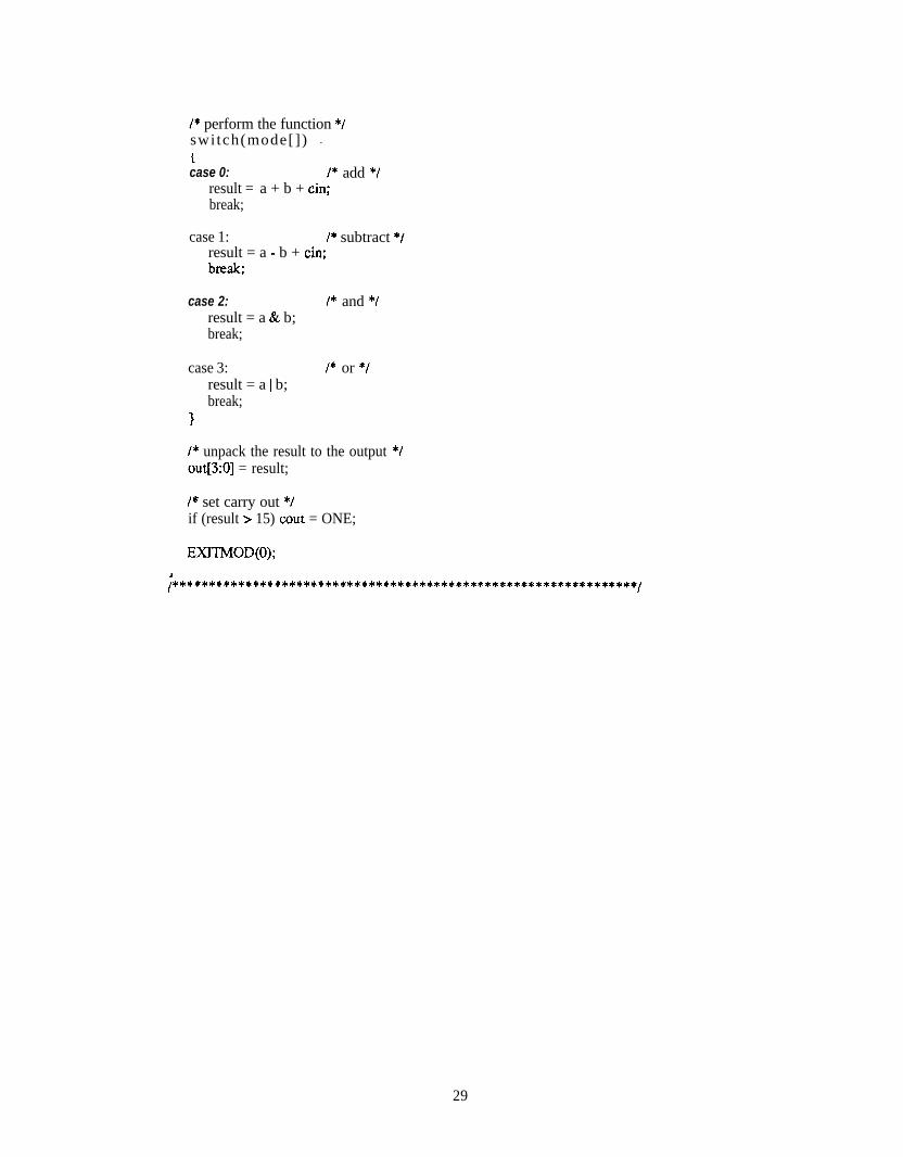
I* perform the function */switch(mode[]) -icase 0: I* add *I
result = a + b + tin;break;
case 1: I* subtract *Iresult = a - b + tin;
case 2:result = a & b;break;
I* and *I
case 3:result = a I b;break;
I* or *I
I* unpack the result to the output *Iout[3:0] = result;
I* set carry out *Iif (result > 15) tout = ONE;
EXITMOD(0);
;****************************************************************/
29


ana( 1) THOR USER’S MANUAL ana( 1)
NAMEana
SYNOPSISana filename
DESCRIPTIONAna takes as input a file created by the banalyzer monitor and pipes the information into the graphicanalyzer. The behavior of the analyzer is the same as when it is being run interactively,
SEE ALSObanalyzer(3) analyzer(3) aview( 1)
31 (1)


aview ( 1) THOR USER’S MANUAL aview ( 1)
NAMEaview - prints banalyzer monitor output in tabular format
SYNOPSISaview [-s] [-f format 1 -ff format-file] [input-file]
DESCRIPTIONAview takes the input-file, a file created by the banalyzer monitor, and prints the results in tabularformat. If no input-file is specified, aview will read from standard input. The rows represent the timeand the columns represent the signals being monitored. The results are printed on the standard output,and the format of the output can be specified by using the -f or -ff switches (see below).
The -s option prints a shortened output file where output is only printed when the signals change.
The -f option allows theas the format command.
user to specify a format for the output. The following argument will be used
The -ff option indicates that the following argument is the filename which contains the formattingcommands.Formatting Commands The formatting commands have the following syntax. Note that non-terminalsare shown in italic and terminals are shown in bold. Symbols enclosed by ‘[I’ imply optionalparameters, symbols enclosed by ‘{}’ imply one or more instances:
FormatComm => FormatEntry ( separator FormatEntry )
separator => : 1 \n
FormatEntry => [ Name = ] SignalList [ @ Base ]
SignalList => signalName { , signalName )
signalName => string 1 Iterator
Iterator => string [ number - number ]
Name => string
Base => binary 1 octal 1 hex 1 x
where Name will be the name printed for the specified group of signals and their value will be shown inthe specified Base. The default name is the common prefix of a group of signals, and the default baseis hex.
The signals will be printed (left to right) in the order in which they are given in the formattingcommands. Signals that appear in the input file but are not listed in any formatting command will beprinted after (to the right) of the formatted signals, using the following format:as a group of signals in base hex if any contiguos signals have a common prefix, otherwise they will beprinted as single signals in binary base. This is the default when no formatting commands are given.
SEE ALSOana( 1) analyzer(3) banalyzer(3)
33 (1)

aview( 1) THOR USER’S MANUAL
AUTHORSomeone should claim responsibility
aview ( 1)
34 (2)
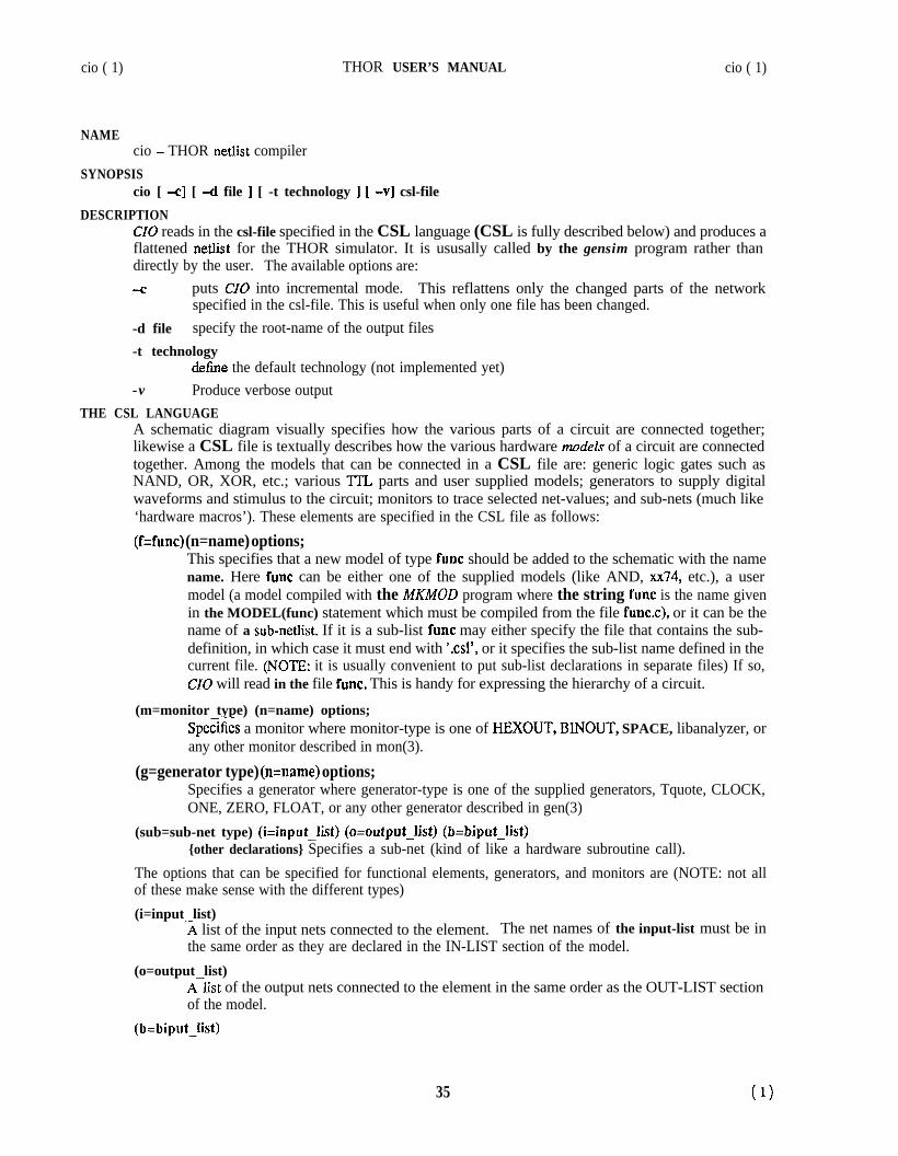
cio ( 1) THOR USER’S MANUAL cio ( 1)
NAMEcio - THOR netlist compiler
SYNOPSIScio [ -cl [ -d file ] [ -t technology ] [ -v] csl-file
DESCRIPTIONCIO reads in the csl-file specified in the CSL language (CSL is fully described below) and produces aflattened netlist for the THOR simulator. It is ususally called by the gensim program rather thandirectly by the user. The available options are:4 puts CIO into incremental mode. This reflattens only the changed parts of the network
specified in the csl-file. This is useful when only one file has been changed.-d file specify the root-name of the output files-t technology
define the default technology (not implemented yet)-v Produce verbose output
THE CSL LANGUAGEA schematic diagram visually specifies how the various parts of a circuit are connected together;likewise a CSL file is textually describes how the various hardware models of a circuit are connectedtogether. Among the models that can be connected in a CSL file are: generic logic gates such asNAND, OR, XOR, etc.; various ‘ITL parts and user supplied models; generators to supply digitalwaveforms and stimulus to the circuit; monitors to trace selected net-values; and sub-nets (much like‘hardware macros’). These elements are specified in the CSL file as follows:
(f=func) (n=name) options;This specifies that a new model of type func should be added to the schematic with the namename. Here func can be either one of the supplied models (like AND, xx74, etc.), a usermodel (a model compiled with the MKMOD program where the string func is the name givenin the MODEL(func) statement which must be compiled from the file func.c), or it can be thename of a sub-netlist. If it is a sub-list func may either specify the file that contains the sub-definition, in which case it must end with ‘.csl’, or it specifies the sub-list name defined in thecurrent file. (NOTE: it is usually convenient to put sub-list declarations in separate files) If so,CIO will read in the file func. This is handy for expressing the hierarchy of a circuit.
(m=monitor type) (n=name) options;Sp&ies a monitor where monitor-type is one of HEXOUT, BINOUT, SPACE, libanalyzer, orany other monitor described in mon(3).
(g=generator type) (n=name) options;Specifies a generator where generator-type is one of the supplied generators, Tquote, CLOCK,ONE, ZERO, FLOAT, or any other generator described in gen(3)
(sub=sub-net type) (i=input-list) (o=output-list) (b=biput-list){other declarations} Specifies a sub-net (kind of like a hardware subroutine call).
The options that can be specified for functional elements, generators, and monitors are (NOTE: not allof these make sense with the different types)(i=input list)
?I list of the input nets connected to the element. The net names of the input-list must be inthe same order as they are declared in the IN-LIST section of the model.
(o=output list)Alist of the output nets connected to the element in the same order as the OUT-LIST sectionof the model.
(b=biput-list)
35 (1)

cio ( 1) THOR USER’S MANUAL cio ( 1)
A list of the biput nets connected to the element in the same order as the BI-LIST section ofthe model.
(vs=initial states)The initial values of the state variables. You don’t need to specify one value for each state(for example if you have a memory with 4096 bytes of state you can specify only one numberand the first state value will change).
(s=# of state variables)This is required ONLY if the vs option is specified. The number of state variables in theST-LIST section of the model. (GRP(x,8) counts as 8 and SIG(x) counts as 1)
(do=output delays)the delay of the output signals (one number per wire or bit in a bus) specified in simulatortime. (NOTE: default value is 1)
(db=biput delays)delays for the biputs (NOTE: default value is 1)
The CSL specification may contain C-like comments (i.e. anything contained within ‘/*’ and ‘*/’ isignored. (actually comments are limited to 2OOO characters in length due to limitations of lex so becareful when commenting out large parts of CSL files)
NAMINGAny legal ‘C’-name can be used to label a net. Busses are specified by brackets (e.g. bus[7-O] for eightbits or bus[2] for a single bit). If you want to leave an output unconnected the net name ‘unc’ shouldbe used as a place-holder. (e.g. (f=xx74ab)(n=Dflipflop)(i=pre-b, elk, d, clr-b) (o-q-out, unc)(s-2); )
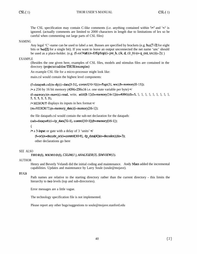
EXAMPLE(Besides the one given here, examples of CSL files, models and stimulus files are contained in thedirectory /projects/cad/dot/THOR/examples)An example CSL file for a micro-processor might look like:main.csl would contain the highest level components:
(f=datapath.csl)(n=dp)(i=data[O-311, control[lO-l])(o=flags[3], unc)(b=memory[O-151);/* a 256 by 16 bit memory (4096=256x16 i.e. one state variable per byte) */(f=memory)(n=mem)(i=read, write, addr[8-l])(b=memory[l6-l])(s=4096)(db=S, 5, 5, 5, 5, 5, 5, 5, 5, 5,5, 5, 5, 5, 5, 5);/* HEXOUT displays its inputs in hex format */
(m=HEXOUT)(n=memory_data)(i=memory[ 16-l]);
the file datapath.csl would contain the sub-net declaration for the datapath:
(sub=datapath)(i=dp-data[32-11, control[lO-l])(b=memory[l6-11);
I* a 3-input or gate with a delay of 3 ‘units’ */
(f=or)(n=decode-or)(i=control[lO-91, dp_data[4])(o=decodex)(do=3);other declarations go here
SEE ALSOTHOR(l), MKMOD(l), CSLIM(l), Ah’ALYZER(3), SIMVIEW(1).
36 (2)

cio ( 1) THOR USER’S MANUAL cio ( 1)
AUTHORHenry and Beverly Velandi did the initial coding and maintenance. Andy Maas added the incrementalcapabilities. Updates and maintenance by Larry Soule (soule@mojave).
BUGSPath names are relative to the starting directory rather than the current directory - this limits thehierarchy to two levels (top and sub-directories).
Error messages are a little vague.
The technology specification file is not implemented.
Sub-net calls should be parameterizable but they aren’t.
Please report any other bugs/suggestions to [email protected]
37 (3)

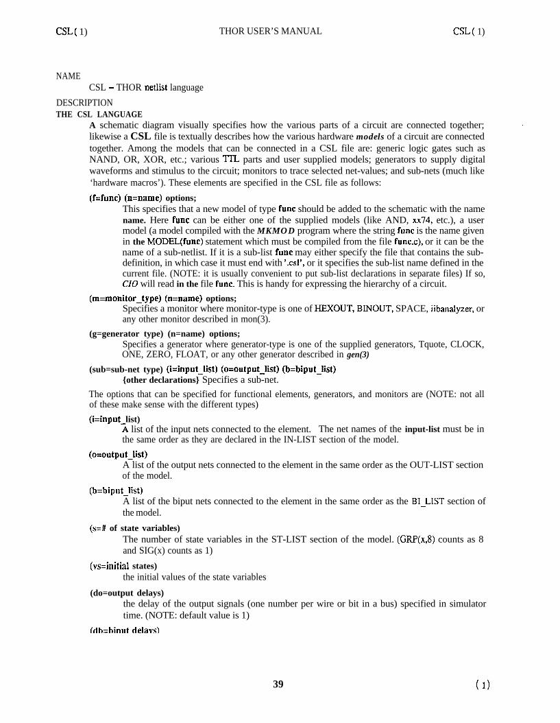
CSL( 1) THOR USER’S MANUAL CSL( 1)
NAMECSL - THOR netlist language
DESCRIPTIONTHE CSL LANGUAGE
A schematic diagram visually specifies how the various parts of a circuit are connected together;likewise a CSL file is textually describes how the various hardware models of a circuit are connectedtogether. Among the models that can be connected in a CSL file are: generic logic gates such asNAND, OR, XOR, etc.; various TILL parts and user supplied models; generators to supply digitalwaveforms and stimulus to the circuit; monitors to trace selected net-values; and sub-nets (much like‘hardware macros’). These elements are specified in the CSL file as follows:(f=func) (n=name) options;
This specifies that a new model of type func should be added to the schematic with the namename. Here func can be either one of the supplied models (like AND, xx74, etc.), a usermodel (a model compiled with the MKMOD program where the string func is the name givenin the MODEL(func) statement which must be compiled from the file func.c), or it can be thename of a sub-netlist. If it is a sub-list func may either specify the file that contains the sub-definition, in which case it must end with ‘.csl’, or it specifies the sub-list name defined in thecurrent file. (NOTE: it is usually convenient to put sub-list declarations in separate files) If so,CIO will read in the file func. This is handy for expressing the hierarchy of a circuit.
(m=monitor-type) (n=name) options;Specifies a monitor where monitor-type is one of HEXOUT, BINOUT, SPACE, iibanalyzer, orany other monitor described in mon(3).
(g=generator type) (n=name) options;Specifies a generator where generator-type is one of the supplied generators, Tquote, CLOCK,ONE, ZERO, FLOAT, or any other generator described in gen(3)
(sub=sub-net type) (i=input-list) (o=output-list) (b=biput-list){other declarations} Specifies a sub-net.
The options that can be specified for functional elements, generators, and monitors are (NOTE: not allof these make sense with the different types)(i=input list)
1 list of the input nets connected to the element. The net names of the input-list must be inthe same order as they are declared in the IN-LIST section of the model.
(o=output-list)A list of the output nets connected to the element in the same order as the OUT-LIST sectionof the model.
(b=biput-list)A list of the biput nets connected to the element in the same order as the BI-LIST section ofthe model.
(s=# of state variables)The number of state variables in the ST-LIST section of the model. (GRP(xJ?) counts as 8and SIG(x) counts as 1)
(vs=initial states)the initial values of the state variables
(do=output delays)the delay of the output signals (one number per wire or bit in a bus) specified in simulatortime. (NOTE: default value is 1)
~dkhiniit delavs1
39 ( 1)
CSL( 1) THOR USER’S MANUAL CSL( 1)
The CSL specification may contain C-like comments (i.e. anything contained within ‘/*’ and ‘*/’ isignored. (actually comments are limited to 2000 characters in length due to limitations of lex so becareful when commenting out large parts of CSL files)
NAMINGAny legal ‘C’-name can be used to label a net. Busses are specified by brackets (e.g. bus[7-O] for eightbits or bus[2] for a single bit). If you want to leave an output unconnected the net name ‘unc’ shouldbe used as a place-holder. (e.g. (f=xx74ab)(n=Dflipflop)(i=pre-b, elk, d, clr-b) (o=q-out, unc)(s=2); )
EXAMPLE(Besides the one given here, examples of CSL files, models and stimulus files are contained in thedirectory /projects/ca&doc/THOR/examples)An example CSL file for a micro-processor might look like:main.csl would contain the highest level components:
(f=datapath.csl)(n=dp)(i=data[O-311, control[lO-l])(o=flags[3], unc)(b=memory[O-151);/* a 256 by 16 bit memory (4096=256x16 i.e. one state variable per byte) */(f=memory)(n=mem)(i=read, write, addr[8-l])(b=memory[16-l])(s=4096)(db=5, 5, 5, 5, 5, 5, 5, 5, 5, 5,5, 5, 5, 5, 5, 5);/* HEXOUT displays its inputs in hex format */(m=HEXOUT)(n=memory$ata)(i=memory[l6-11);
the file datapath.csl would contain the sub-net declaration for the datapath:(sub=datapath)(i=dp-data[32-11, control[lO-l])(b=memory[16-11);
/* a 3-input or gate with a delay of 3 ‘units’ */(f=or)(n=decode-or)(i=control[lO-91, dp_data[4])(o=decodex)(do=3);other declarations go here
SEE ALSOTHOR(l), MKMOD(l), CSUM(I ), ANALYZER(3), SIMVIEW(1).
AUTHORHenry and Beverly Velandi did the initial coding and maintenance. Andy Maas added the incrementalcapabilities. Updates and maintenance by Larry Soule (soule@mojave).
BUGSPath names are relative to the starting directory rather than the current directory - this limits thehierarchy to two levels (top and sub-directories).
Error messages are a little vague.
The technology specification file is not implemented.
Please report any other bugs/suggestions to [email protected]
40

CSLIM( 1) UNIX Programmer’s Manual CSLIM( 1)
NAMEcslim -’ PLA Generator for THOR
SYNOPSIScslim [ -xsqd[n]] [ file ]
DESCRIPTIONCSLlM takes a finite state machine model written in a subset of THOR(I), and calculates the PLAequations for espresso(l) optimization and eventually a PLA generator.
USAGE.If a file name is given on the command line, input is read from that file; otherwise, input is read from
stin. The output is written to stdout, and is usually piped through espresso. For final PLA’s, use the-do qm option to increase the optimization level, realizing that this will slow it down. Thus,
cslim infi1e.c 1 espresso -do qm > foo.tt
The -q option turns off the checking for unset outputs, and initializes all outputs to undefined at thebeginning of the model. By default, the program will insure that each output is set in every possibleflow through the model, and complain about those that might not be set. This flag will turn off thosecomplaints.The -x option turns off the handling of undefined cases in switch statements. If you perform a switchon a group, and do not specify the full range of possible values, and don’t provide a default condition,the program will assume that the other cases are not possible, and add the cases not mentioned to thedon’t care set. If you turn on this option, empty default statements will not be handled like this.The -s option allows you to automatically store state in your PLA for those state bits that are notassigned If you set this option, the generated PLA will be larger, but it will stay in the same stateunless you specifically assign it to be something else. Normally, if you do not assign the state in everypossible flow through the program, it is an error that will be caught by the unset outputs checking.The -d option in cslim turns on the debug mode; there are threeand -d3. Each level prints out increasing amounts of information.
levels of debug, turned on by -4 -d2,
INPUT FORMATInput is a restricted THOR model of a finite state machine, Sections of code you want ignored byCSLIM can be enclosed in { { }} or /*{ { */ /*}}*/; this is essential for all parts of the THOR modelwhich do not pertain directly to the logical function of the PLA, such as clock triggering. The typechecking in CSLIM is more rigorous than that in THOR; you cannot assign an arbitrary integer value toa SIG, even if it is a state SW; you must use funpack and fpack() (or their abbreviations grp[] andgrp[n:m]; see n&mod(l)) on a declared GRP. Only the switch and if control constructs are allowed.Conditionals are limited to -- and !-, with &&, I], !, and () operators. Each comparison must comparea SIG to a signal type (ONE, ZERO, FLOAT, or UNDEF) or the value of funpack of a GRP to aninteger. Each switch element must have a single label, and must be terminated by a break. Nesting ofcontrol structures is arbitrary, allowing, for instance, easy RESET of a PLA. All input, output, or statevariables not a direct part of the PLA must be ‘commented out’ with the double curly braces above.Output signals can be assigned multiple times; for instance, all outputs might be initialized at the headof the model, and then conditionally changed.
OUTPUT FORMATThe output is a fully specified function consisting of an ON-set and an OFF-set, in the ‘fr’ format ofespresso. The input, output, and state signal names are also written for inclusion in the PLA. Seeespresso(5) for a description of the format.
DIAGNOSTICS
41 (1)

CSLIM( 1) UNIX Programmer’s Manual CSLIM( 1)
In case of a syntax error, the offending line and a character pointer is printed out. Currently nodescription of the error is printed; a parse failure is simply returned. If a GRP is compared to aSIGNAL or a SIG is compared to an integer, a warning message is printed.
SEE ALSOespresso(l), mkmd(l), espresso(5), THOR(l).
AUTHORTomas Rokicki ([email protected]).
BUGSOutput diagnostics are terrible.
You can’t specify the order of the bits of a group in the output equations.
The use of /*{{*//*}}*/ and (0) is rather ugly.
If a state variable is not assigned during execution of the model in THOR, and then checked, the THORmodel execution will not reflect the PLA generated. Do not do this.
42 ( >2

gensim ( 1) THOR USER’S MANUAL gensim ( 1)
NAMEgensim - generates the simulator for the given network
SYNOPSISgensim root.csl...
[ user-model.0 I...[ -t #time-steps I...[ -x 1 E -i 1 [ -f 1
root.exe [ -i ] [ -f ] [ -t #time-steps ] [ > output-file ]
DESCRIPTIONGensim generates the executable simulator. It runs the CSL compiler cio on the specified network files,links the simulator with the user defined models, and generates the simulator for the network. Note thatthe network file specified must be the root of the network to simulate. All other arguments areoptional.The options with their default values are as follows:user-model.0
No default. Link with one or more user defined models. The models must first be compiIedwith mkmod. See n&mod(l). Note that gensim will automatically include models specific tothe given network. However, this option allows user libraries to also be included.
- X
- i
- f
When this flag is present, the simulator executable will be built, but not run.When this flag is present, the simulator will run in interactive mode, to speed the debuggingprocess.When this flag is present, the simulator will run in compiled mode insteadmode. This is a faster way to simulate circuits at the higher abstraction levels.
of event-driven
-t #time-stepsThis option allows the number of time steps simulated to be set. The default is 1000.
Cio is run automatically by gensim. Cio is the compiler that reads the network description files andproduces a detailed description of the network for the simulator. Although cio can be run by itself, thereasons to do so are being eliminated.The models that were specified in the network are linked with the actual simulator code to produce theexecutable simulator. The simulator reads the files produced by cio to get the network connectivity,output delays, etc. The simulator can also be executed by root concatenated with .exe with possibleoptions of simulation time, specified with the -t option. The simulator sends its output (which is theoutput from the monitor models) to stdout. Error messages go to stderr.
FILESroot.exe simulator executableroot.out output from simulation runroot.elm element information, from cioroot.con network connectivity, from cioroot.sys list of models used, from cioro0t.c model function address table, from cio
SEE ALSOTHOR( 1) mkmod( 1) cio( 1) simview( 1)
AUTHORSModified bv Sun Young Hwang and Robert Alverson
43 (1)

gensim( 1) THOR USER’S MANUAL
Written by Henry and Beverly VelandiUniversity of Colorado, Boulder
44
gensim ( 1)
(2)
intTHOR ( 1) THOR User’s Manual intTHOR ( 1)
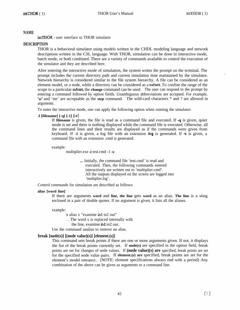
NAMEintTHOR - user interface to THOR simulator
DESCRIPTIONTHOR is a behavioral simulator using models written in the CHDL modeling language and networkdescriptions written in the CSL language. With THOR, simulation can be done in interactive mode,batch mode, or both combined. There are a variety of commands available to control the execution ofthe simulator and they are described here.
After entering the interactive mode of simulation, the system writes the prompt on the terminal. Theprompt includes the current directory path and current simulation time maintained by the simulator.Network hierarchy is considered similar to the file system hierarchy. A file can be considered as anelement model, or a node, while a directory can be considered as a subnet. To confine the range of thescope to a particular subnet, the change command can be used. The user can respond to the prompt byentering a command followed by option fields. Unambiguous abbreviations are accepted. For example,‘St’ and ‘ste’ are acceptable as the step command. The wild-card characters * and ? are allowed inarguments.To enter the interactive mode, one can apply the following option when running the simulator:4 [filename] [-q] [-1] [-cl
If filename is given, the file is read as a command file and executed. If -q is given, quietmode is set and there is nothing displayed while the command file is executed. Otherwise, allthe command lines and their results are displayed as if the commands were given fromkeyboard. If -1 is given, a log file with an extension .log is generated. If -c is given, acommand file with an extension .cmd is generated.
example:multiplier.exe 4 test.cmd -1 -c
. . . Initially, the command file ‘test.cmd’ is read andexecuted. Then, the following commands enteredinteractively are written out to ‘multiplier.cmd’.All the outputs displayed on the screen are logged into‘multiplier.log’.
Control commands for simulation are described as follows:alias [word line]
If there are arguments word and line, the line gets word as an alias. The line is a stingenclosed in a pair of double quotes. If no argument is given, it lists all the aliases.
example:> alias x “examine in1 in2 out”. . . The word x is replaced internally with
the line, examine in1 in2 out.Use the command unalias to remove an alias.
break [node(s)] [(node value)(s)] [element.(s)]This command sets break points if there are one or more arguments given. If not, it displaysthe list of the break points currently set. If node(s) are specified in the option field, breakpoints are set for changes of node values. If (node value)(s) are specified, break points are setfor the specified node value pairs. If element.(s) are specified, break points are set for theelement’s model entrance.. (NOTE: element specifications always end with a period) Anycombination of the above can be given as arguments to a command line.
45 ( )1

intTHOR ( 1) THOR User’s Manual intTHOR ( 1)
> break orlint . . . break on change of value of node or1 .inl> break (orl.inl 1) . . . break when node orl.inl gets value 1> break orl. . . . break on activation of element or1
Break points are reset with the clear command.change directorypath
This command changes the working directory in hierarchical network to the directory specifiedby the argument. Root directory and parent directory are designated by ‘$’ and ‘-‘,respectively.
example:> change ^.adder. . . Changes the working directory to the sub-network ‘adder’
in the parent directory.> change $.adder.xor. . . Changes the working directory to the sub-network ‘xor’,
two levels down from the root directory. Root directorymeans a topmost circuit description in a hierarchical network.
clear [number(s) or *]This command clears break points currently set, With the argument +, it clears all the breakpoints. Otherwise, it clears break point(s) specified by the number(s). Each break point isgiven with a unique number so that it can be cleared easily by specifying the number. Thenumber can be obtained with the break command without arguments.
example:> clear 2
connectivity [node or element.]This command is used to examine the circuit connectivity. If node is given as an argument, itdisplays all the elements connected to the node with their pin numbers and pin names. Ifelement is given, it displays all the nodes connected to the pins of the element. (NOTE:element specifications end with a period)
example:> connectivity adder.xor2.> connectivity adder.xor2.in 1
deposit (node value)(s)This command temporarily sets the values of the specified nodes to the specified values. Asthe simulation proceeds, the values may change.
example:> deposit (adder.xor2.inl 0)
disable [number(s) or *]This command disables the dump of node values. If * is given, it disables all the nodes.Otherwise, it disables the dump only for the nodes specified by the number(s). The numberscan be obtained with the enable command without arguments.
example:> disable 2
dump This command dumps the values of enabled nodes.
46 ( >2

intTHOR ( 1) THOR User’s Manual
This command is used to examine nodes of elements every time the simulation stops or thedump command is issued If a node is specified as an argument, it enables the dump of thenode values. If an element is specified as an argument, it enables the dump of the state andpin values of the element. Without any argument, it displays the list of the enabled nodes andelements.
example:> enable adderxorl .in 1
Enabled nodes or elements are disabled with the disable command.
examine [node(s)] [element.(s)]If a node is specified, it displays the current value of the specified node. If an element isspecified, it displays the state and pin values of the specified element.
example:> examine muxl .and2.*
produces the output like:muxl.and2.inl = 0muxl.and2.in2 = 1muxl.and2.out = 0
exit This command is for exiting the simulator. It is equivalent to the quit command.freeze [node(s)] [(node value)(s)]
This command freezes nodes if there are one or more arguments given. Otherwise, it displaysthe list of the nodes currently frozen. If node(s) are specified, the nodes are frozen to currentvalues. If (node value)(s) are specified, the nodes are frozen to the specified values.
example:> freeze adder.xor 1 .in 1> freeze (adder.xorl.inl 1)
go [[+]time]This command starts simulation and continues until max_time is reached, if there are noarguments. If + is omitted, the simulation continues till absolute time is reached. + meansrelative time unit and the simulation stops time steps after current simulation time.
example:> go +lO . . . simulates for 10 time units.> go loo . . . simulates to absolute time 100.
help
mark
This command displays help information about each command with examples.This commandtime.
marks the current time so that later the simulation can be restarted from this
quit This command is for exiting the simulator. It is equivalent to the exit command.restart This command restarts simulation from the
not been marked, it restarts from time 0.time marked by the mark command. If a time has
run filenameThis command reads command lines from the command file specified by filename and executesthem. The command file can be created by the user with an editor or by the simulator forsimulation rerun. The latter can be done by setting the variable cmd-file to 1 (see setcommand).
set (variable [value])(s)This command sets variables to values. Allowed Variables are max-time, timeunit, log,
47 ( 3)

intTHOR ( 1) THOR User’s Manual intTHOR ( 1)
cmd-file, and quiet. max-time is the maximum time units that are simulated. The defaultvalue is 1000. timeukit is time units per step. The default value is 1. If log is set to 1, a logfile(filename.log) is created. The default value is 0. If cmd-file is set to 1, all the commandsexecuted during simulation are written to a file(filename.cmd) such that one can rerun the samecommands. The default value is 0. If quiet is set to 1, the commands read from command fileare executed in quiet mode. Otherwise, all the command lines and their results are displayedon the CRT screen while the simulator runs. The default value is 0.
example:> set (max-time 500). . . allows simulator to run up to 500 absolute time units.
show variable(s)This command displays the values of variables. Allowed variables are max-time, timeunit,log, cmd-file, and quiet.
example:> show max time-
step This command simulates for one time unittrace [node(s)] [(node value)(s)] [element.(s)]
This command sets traces if there are one or more arguments given. If not, it displays the listof the nodes and elements set for traces. If node(s) are specified, the nodes are set for tracesof changes of node values. If (node value)(s) are specified, the nodes are set for traces ofspecified node values. If element.(s) are specified, traces are set for model entrances of thespecified elements. That is, it traces the evaluation of the elements.
example:> trace adder.xorl.inl> trace (adder.xorl .inl 1)> trace adder.xorl.
unalias [number(s) or *]This command removes aliases. If * is given, it removes all the aliases. If number(s) aregiven, it removes the specified alias(es). The numbers can be obtained with the aliascommand without arguments.
unfreeze [number(s) or *]This command unfreezes frozen nodes. With *, it unfreezes all the frozen nodes. Otherwise,it unfreezes nodes specified by the number(s). The numbers can be obtained with the freezecommand without arguments.
example:> unfreeze 2
untrace [number(s) or *]This command resets traces currently set. If * is given, it resets all the traces. Otherwise, itresets the trace settings specified by the number(s). The numbers can be obtained with thetrace command without arguments.
example:> untt-ace 2
!string The string is ignored. It is accepted as a comment line.
48 (4

intTHOR ( 1) THOR User’s Manual
SEE ALSOTHOR( 1) gensim( 1)
AUTHORSKiyoung ChoiStanford University
BUGSPlease report any bugs to [email protected]
intTHOR ( 1)
49


*WV Mkmod and epp description mkmod( I)
NAMEn&mod, epp - description of r&mod and epp, and introduction to THOR models
SYNOPSISmkmod [ -p ] [ -m ] file [ cc options ]epp 1 -d [ n 1 I file
DESCRIPTIONMkmod is the THOR model compiler. It runs epp over the model to convert the THOR constructs intoC constructs, and then invokes the C compiler.
Epp is the THOR model preprocessor, which is used to convert signal and group declarations into theappropriate C code, and convert implicit uses of groups into the necessary function calls. The usershould never need to call this directly; mkmod -p will generate just the preprocessed output.
USAGEFor n&mod, the file name must not have a suffix; .c is added to find the source. Any options givenafter the flle name are passed on to the C compiler.-m
-P
Compile as a main program. This will compile andoption, the model is only compiled into an object file.Only run through epp; no compilation is attempted.
attempt to link your file; without this
For epp, the file name must be given in full; output is written to standard output. Signal and groupdeclarations are changed to C code; implicit group usage is changed to function calls (for instance, a[]= b[] is changed to funpack(a, 0, n, fpack(b, 0, n)).-d Turn on debug mode; this is optionally followed by a single digit which can be used to set the
debug level higher.Both mkmod and epp use the THOR environment variables; see THOR(l) for information about these.
INPUT FORMATThe input to n&mod is a THOR model, essentially written in C. This model consists of the followingsections:
Model header
Input, output, biput, and state signals and groups
Initialization section (optional)
The model header consists of the keyword MODEL, with the name of the model in parenthesis,followed by an open brace. This name will be given in the (f=...) section of the CSL.
Following this are the input, output, biput, and state signal and group declarations. These start withIN-LIST, OUT-LIST, BI-LIST, and ST-LIST respectively, and end with ENDLIST. Inside eachsection are declarations for signals and groups. The order within each group must match the order ofthe signals and groups within the CSL; the names can be different. The declarations possible are:
SIG(name) Declares a single wire called name.
GRF’(name, size [, (BIGENDIAN]LITTLEENDIAN}]) Declares a group (or bus) of size wires.If a third argument is given, it must be one of BIGENDIAN or LITTLEENDIAN, and it specifies thedefault bit ordering of the group when it is used as an integer; BIGENDIAN is the format used by
51 ( >1

Mkmod and epp description owl)
Motorola, for instance, with the most significant bit being the one with the highest number, andLITI’LEENDIAN is used in IBM mainframes, with the most significant bit being bit 0. If the thirdargument is omitted, BIGENDIAN is assumed.
VGRP(name) Declares a group of unknown size. There can only be one of these for eachsignal section (input, output, biput, and state) and it must be the last declaration. This is useful forcreating parameterized models.
TSIG(name) Declares a temporary (internal) signal.
TGRP(name, size [, {BIGENDIANILITTLEENDIAN}]) Declares a temporary (internal) group.
BUS and REG are synonyms for GRP; likewise, VBUS and VREG for VGRP.
The model body can include any standard C statements or functions. Signals are integer variableswhich can take on four values: ONE, ZERO, FLOAT, and UNDEF. Groups are arrays of signals; thesecan be accessed as individual signals by g[3] to get the third signal of group g, for instance. Inaddition, entire groups can be packed into an integer value or integer values put onto a group throughthe fpack and funpack procedures described below. They may also be referred to by following them byexpressions in brackets, as:
g[] means the entire group interpreted as an integer; it takes on values from 0 to 2%-l, wherethere are n bits. A negative number indicates that one of the signals in the group is floating orundefined.
g[n] means the nth signal of group g; it can take on values ONE, ZERO, FLOAT, or UNDEF.
g[n:m] means signals n through m of group g interpreted as an integer; takes on values from 0to 2^(m-n+l)-1. Again, a negative number indicates that one of the signals in the group is floating orundefined. The first number (n) is used as the most significant bit; the second is used as the leastsignificant.
Any of these three formats can be used as a value or as the left hand side of an assignment statement.
The initialization section (if one exists) must begin with INIT and end with ENDINIT. Any statementscan be executed within the initialization section, such as initializing some state variables or setting upan internal array.
The body of the model is executed whenever the values of one of the input or biput signals or groupschanges, It must be exited with the EXITMOD(value) statement; a non-zero value indicates an error.Any number of EXITMOD(value) statements can be used.
EXAMPLEHere is a small example of a model and an explanation of its function.I*
* This is an example model for a* 74138-like 3 to 8 demultiplexor.* Three enable inputs, two active* low, and the three inputs and* eight outputs. The name this* model should be referred to in* the csl is ‘mux’.*I
52 (2)
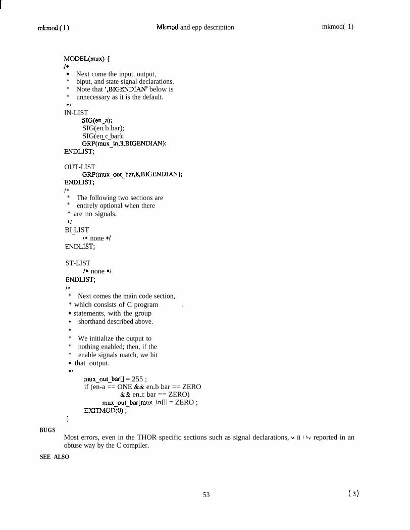
owl) Mkmod and epp description
MODEL(mux) {I*
* Next come the input, output,* biput, and state signal declarations.* Note that ‘,BIGENDIAN’ below is* unnecessary as it is the default.*I
IN-LISTSIG(en-a);SIG(en b bar);- -SIG(en c bar);GRP(m~x~in,3,BIGENDIAN);
ENDLIST;
OUT-LISTGRP(mux_out_bar,8,BIGENDIAN);
ENDLIST;I*
* The following two sections are* entirely optional when there* are no signals.*I
BI LIST-/* none */
ENDLIST;
ST-LISTI* none */
ENDLIST;I*
* Next comes the main code section,* which consists of C program .* statements, with the group* shorthand described above.** We initialize the output to* nothing enabled; then, if the* enable signals match, we hit* that output.*I
mux-out-bar[] = 255 ;if (en-a == ONE && en b bar == ZERO- -
&& en c bar == ZERO)- -mux-out-bar[mux-inn] = ZERO ;
EXITMOD(0) ;
mkmod( 1)
BUGSMost errors, even in the THOR specific sections such as signal declarations, LI II i tbc: reported in anobtuse way by the C compiler.
SEE ALSO
53 (3)

Mkmod and epp description
cio( 1)cslim( 1)THOR( 1)
AUTHORSWritten by Henry and Beverly VelandiUniversity of Colorado, Boulder
Minor modifications to mkmod andrewrite of epp by Tomas RokickiStanford University
*wl)
54 (4)

simview ( 1) THOR USER’S MANUAL simview ( 1)
NAMEsimview - prints simulator output in tabular format
SYNOPSISsimview [-s] [input-file-name]
DESCRIPTIONSimview takes the input-file-name, a file in THOR format, and prints the results in tabular format. Ifno input-file-name is specified, simview will read from standard input. The rows represent the timeand the columns represent the signals being monitored. The results are printed on the standard output.The -s option prints a shortened output file where output is only printed when the signal changes.The simulator output file format is:
1) The first line in the file is the maximum time reached during simulation
2) The format of subsequent lines is:
time monitor name- value
where, time is the time the monitor was called, monitor-name is the name of the monitor, andvalue is the value of the monitor input at this time. Value is an arbitrary string of any length,but this length must remain constant for a given monitor or the columns will not line up in theoutput from simview.
3) Note, all monitors are called by the simulator at time zero.FILESSEE ALSOBUGSAUTHOR
Peter MoceyunasUniversity of Colorado, Boulder
55 ( >1


THOR( 1) THOR User’s Manual THOR( 1)
NAMETHOR - introduction to THOR commands and applications programs
DESCRIPTIONTHOR is a behavioral simulator using models written in the CHDL modeling language (a hardwaredescription language based on the “C” programming language) and network descriptions written in theCSL language. There are a variety of commands available to control the execution of THOR (gensim)and to develop models that are simulated using THOR. The simulation can be done in interactivemode, batch mode or both combined. The simulator output can be printed in tabular format usingsimview or processed and displayed in waveform using analyzer. A detailed description and a usertutorial may be found in the THOR tutorial (THORtutor(1)).The basic entity used in formulating THOR networks is the model which represents a hardware device.These models are linked together to form a network using the CSL network definition language. Cioreads this network description, compiles it, and produce a detailed description for the simulator.Models are written using the CHDL modeling language and compiled by mkmd to produce objectcodes for the simulator. There are useful functions which may be used in formulating models.Functions are logical or behavioral units that are called by a model just as a function is called in “C”.These functions return a value to the model on return after they are finished executing. As an aid forthe model synthesis, cslim generates an optimized PLA from a finite state machine model written inCHDL.
SEE ALSOGeneral
=Ml)aview( 1)cio( 1)cslim( 1)intTHOR( 1)*wl)gensim( 1)
simview( 1)THORtutor( 1)sirnint(5)
- pipes banalyzer monitor output into graphic analyzer- prints banalyzer monitor output in tabular format- compiles network description files written in CSL- generates PLA from a finite state machine model- user interface to THOR simulatorm compiles a model written in CHDL- generates executable simulator,
and controls execution of THOR- prints simulator output in tabular format- THOR tutorial- interface to Rsim, chip tester, etc.
General purpose models
analyzer(3)banalyzer( 3)gen(3generic( 3)mon( 3)ttl( 3)
- a monitor which displays its inputs graphically- batch analyzer monitor- describes the signal generator models available- describes generic gates, (AND,NOR,etc)- describes the signal monitor models available- describes the ttl models available
General purpose functions used in models
current-time(3)muMQ31fadd( 3)faddc( 3)
- a copy of the simulator’s absolute time variable- macros used when debugging is desired in a function- adds two n-bit groups with carry-in/out- adds n-bit group to a constant
57
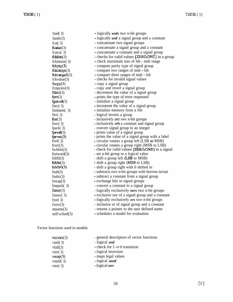
THOR( 1) THOR( 1)
fand( 3)fandc(3)fcat( 3)fcatac( 3)fcatca( 3)fckbin( 3)fckmsize( 3)fchn0)fckrange( 3)f&range3 (3)fckvalue(3)fcopy(3)fcopyinv(3)fdecr( 3)ferr( 3)fgetval( 3)fincr( 3)finitmem( 3)finv( 3)fior( 3)fiorc( 3)fpack( 3)fprval( 3)fprvec(3)frorl( 3)frorr(3)fsckbin(3)fsetword(3)fshftl(3)fshftr( 3)fshftrO(3)fsub(3)fsubc(3)fswap(3)funpack( 3)fxnor( 3)fxnorc( 3)fxor( 3)fxorc(3)mname(3)self-sched(3)
Vector functions used in models
- logically ands two n-bit groups- logically and a signal group and a constant- concatenate two signal groups- concatenate a siganl group and a constant- concatenate a constant and a signal group- checks for valid values {ZE!RO,ONE} in a group- check maximum size of lsb - msb range- compute parity type of signal group- compare two ranges of msb - lsb- compare three ranges of msb - lsb- checks for invalid signal values- copy a signal group- copy and invert a signal group- decrement the value of a signal group- prints the type of error requested- initialize a signal group- increment the value of a signal group- initialize memory from a file- logical inverts a group- inclusively ors two n-bit groups- inclusively ors a constant and signal group- convert signal group to an integer- prints value of a signal group- prints the value of a signal group with a label- circular rotates a group left (LSB to MSB)- circular rotates a group right (MSB to LSB)- check for valid values {ZERO,ONE} in a signal- set n-bit group to a logical value- shift a group left (LSB to MSB)- shift a group right (MSB to LSB)- shift a group right with 0 shifted in- subtracts two n-bit groups with borrow-in/out- subtract a constant from a signal group- exchange bits in signal groups- convert a constant to a signal group- logically exclusively nors two n-bit groups- exclusive nor of a siganl group and a constant- logically exclusively ors two n-bit groups- inclusive or of signal group and a constant- returns a pointer to the user defined name- schedules a model for evaluation
vectors( 3)vand( 3)vfall(3)vinv( 3)vmap(3vnand( 3)vnor( 3)
- general description of vector functions- logical and- check for 1 -> 0 transition- logical inversion- maps legal values- logical nand- logical nor
58
THOR( 1)
vor( 3)vrise(3)vtbuf(3)vtbufi(3)vwW)vYcnor(3)vxor( 3)
THOR User’s Manual
- logical or- check for 0 -> 1 transition- single bit t&state buffer- single bit inverting tri-state buffer- CMOS transmission gate- logical exclusive nor- logical excutive or
AUTHORSMmed by members of CAD groupStanford University
Written by Henry and Beverly VelandiUniversity of Colorado, Boulder
NAMETHORtutor - THOR tutorial
THOR( 1)
59 (3)