This Safety Alert Symbol Indicates Important
58
Transcript of This Safety Alert Symbol Indicates Important


A This Safety Alert Symbol Indicates Important Safety Messages In This Manual When You See This Symbol Carefully Read The Message That Follows and Be Alert To The Possibility Of Personal Injury Or Death
IF T H I S M A C H I N E IS USED BY A N E M i L O Y E E O R IS L O A N E D O R R E N T E D , M A K E A B S O L U T E L Y C E R T A I N T H A T T H E O P E R A T O R ( S ) , P R I O R T O O P E R A T I N G :
1 . IS I N S T R U C T E D I N S A F E A N D PROPER USE.
2. R E V I E W S A N D U N D E R S T A N D S T H E M A N U A L ( S ) P E R T A I N I N G T O T H E M A C H I N E .
75 1 2 5 3
^ W A R N I N G B E F O R E S T A R T I N G E N G I N E
STUDY OPERATOR'S MANUAL S A F E T Y MESSAGES READ A L L S A F E T Y SIGNS ON MACHINE C L E A R THE A R E A OF OTHER PERSONS
LEARN & PRACTICE S A F E USE OF CONTROLS B E F O R E OPERATING
I I I S V O U R H L b P ( ) N i , I B I l l | v l O U N D E R S F A N D A N D F O L L O W M A N U F A C T U R E R ' S I N S T R U C T I O N S O N M A C H I N E O P E R A T I O N , S E R V I C E . A N D l O O b S E R V E P E R T I N E N T L A W S A N D R E G U L A T I O N S O l ' E H A T O H A N D S E R V I C E M A N U A L S M A Y B t O H ' A I N E O F R O M Y O U R E Q U I P M E N T D E A L E R

TABLE OF CONTENTS
S A F E T Y R U L E S II - X I I I
I N T R O D U C T I O N 2
S E R I A L N U M B E R 4
O V E R A L L M E A S U R E M E N T S 5
G E N E R A L S P E C I F I C A T I O N S 6
E N G I N E S P E C I F I C A T I O N S 7
F U E L S P E C I F I C A T I O N S 8 - 9
L U B R I C A T I O N 1 0 - 1 2 Lubricat ion Chart 11 Engine Lubricat ion 12
O P E R A T I N G I N S T R U C T I O N S 1 3 - 1 9 Operating Controls 1 3 - 1 5 Pre-Starting Check L is t 1 5 Run In Procedure > - . 15 Mounting and Dismounting the Riding L a w n Mower 15 Starting Procedure 16 Stopping the Engine 17 Lawn Mowing 1 8 - 1 9
P R E V E N T I V E M A I N T E N A N C E A N D A D J U S T M E N T S 2 0 - 4 0 Engine Maintenance 2 1 - 2 4
Air Deaner 21 Cleaning Engine Cool ing Air Intake Screen 21 Carburetor Adjustment 22 Engine Lubr icat ion {See L U B R I C A T I O N ) 1 2 Spark Plug 24
Toe In Adjustment 25 Battery and Battery Charger 2 6 - 2 9 Tract ion Drive Maintenance 3 0 - 3 2
Adjusting The C lu tch L i n k 31 Frict ion Drive Wheel Replacement 30 Drive Belt Replacement 3 2
Mower Drive Belt Service 34 Mower Deck Service 3 5 - 3 8
Wiring Diagram 39 Storing the Riding L a w n Mower 4 0 - 4 1
A T T A C H M E N T S 4 3

SAFETY MESSAGES
The t w e n t y - t h r e e safety messages w h i c h f o l l o w are p r o v i d e d by the A m e r i c a n Na t i ona l Standards Ins t i t u te * ( A N S I ) . Sa fe ty rules t o s u p p l e m e n t those p r o v i d e d b y A N S I also appear on the f o l l o w i n g pages.
S tudy these rules ca re fu l l y be fore s ta r t i ng and ope ra t i ng y o u r Case R id ing L a w n M o w e r .
* Rule N u m b e r 10 has been m o d i f i e d f o r greater safety and r j l e n u m b e r 2 4 , w h i c h does no t app ly t o th is p r o d u c t , has been o m i t t e d .
A C A U T I O N ; K n o w the c o n l r o l s and h o w t o s t o p q u i c k l y . R E A D T H E O W N E R ' S M A N U A L
A C A U T I O N : D o n o t a l l o w c h i l d r e n t o operate the veh ic le . Do n o t a l l o w adu l t s t o ope ra te i t w i t h o u t p r o p e r i n s t r u c t i o n .
A C A U T I O N : D o n o t car ry passengers. Keep c h i l d r e n and pets a safe d is tance away .
A. C A U T I O N : Clear the w o r k area of ob jects w h i c h m i g h t he p i c ked up and t h r o w n .
A C A U T I O N : Disengage all a t t a c h m e n t c lu tches .'ind sh i f t i n to neutral be fo re a t t e m p t i n g to s tar t the eng ine ( m o t o r ) .
A C A U T I O N : Disengage p o w e r to a t t a c h m e n t ( s ) uuzi s top the engine ( m o t o r ) be fo re leaving the ope ra to r ' s [posi t ion.
- II •
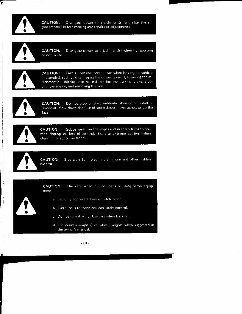
C A U T I O N : Disengage p o w e r t o a t t a c h m e n t i s ) and s top the engine ( m o t o r ) be fore m a k i n g any repairs or ad jus tmen ts .
A C A U T I O N : Disengage p o w e r to a t t a c h m e n t ( s ) w h e n t r a n s p o r t i n g or n o t in use.
A C A U T I O N : Take atl possible p recau t i ons when leaving the veh ic le u n a t t e n d e d , such as d isengaging the p o w e r take -o f f . l o w e r i n g the at-t a c h m e n t ( s ) , sh i f t i ng i n t o n e u t r a l , se t t ing the p a r k i n g brake, s topp ing the engine, and r e m o v i n g the key .
A C A U T I O N : Do n o t s t o p or s tar t sudden l y when go ing u p h i l l o r d o w n h i l l . M o w d o w n the face of steep s lopes; never across or up the face,
A C A U T I O N : Reduce speed on the slopes and in sharp tu rns t o preven t t i pp i ng or loss of c o n t r o l . Exerc ise e x t r e m e c a u t i o n w h e n chang ing d i r e c t i o n on slopes.
C A U T I O N : Stay a ler t for holes m the te r ra in and o t h e r h i d d e n
C A U T I O N : Use care when p u l l i n g loads or using heavy equ ip-miMit .
a. Use o n l y a p p r o v e d r l rawbar h i t c h po i r t t .
b. L i m i t loads t o those y o u can safe ly c o n t r o l .
c. D o n o t t u r n sharp ly . Use care w h e n back ing .
d. Use c o u n t e r w e i g h t l s l or wheel weights w h e n suggested in the oi/vner's manua}.
- I l l -

C A U T I O N : Wa tch o u t ft ir t r a f f i c w h e n crossing ot near roa f lways .
C A U T I O N : When using any a t tachmen ts , never r i i iec t ciischarge of mate i ia l t o w a r d bystanders nor a l l o w anyone i iyar t he vehic le
^^^P^^^k wh i le in o p e r a t i o n .
C A U T I O N : Handle gasol ine w i l h car(? - i l is h igh l y f l a m m a b l e ,
a. Use a | )proved gasol ine co f i ta ine r .
\). Never rnn iove the cap of the fue l tank o i add gasol ine to a rL inning oi h o t eng ine, nr f i l l the fuel t a n k i ndoo rs . Wi[)e up spillfMJ gasol ine.
c. O i ien dt jors if the eni j ine is run in the cjarage exhaust fumes are danger oris. D o no t run the' enj i t ir^ ( m o t o r ) indoor s.
C A U T I O N : Keep the vehic le and a t t achmen ts in g o o d ope ra t i ng c o n d i t i o n , ani l keep safety devices in [ i lace.
C A U T I O N : Keep all nu ts , bo l t s , and scievvs t i gh t t o be sure the I ' qu ipment is in srde w o r k i n g c o n d i t i o n .
A C A U T I O N : Never store the e i j u i i j m e n t w i t h gasolme in the tank inside a Liui ld ing where fumes may reach an o p e n f lame or spa 'k . A l l o w thi.* engine to coo l bi.dure s to r ing in any enc losur i ' .
A C A U T I O N : T o reduce f i re hazard, keef i the engine f ree of grass, leavers, or excessive gn jasc
- I V -

A C A U T I O N : T|-ie vehic le and a t l a c h m e n t s shou ld be s t o p p e d and inspected fo r damage after s t r i k i ng a fo re ign ob jec t , and the damage shou ld be repa i red l ie fore res tar t ing and o[)erat in ' ] the equ i iament .
C A U T I O N : Do n o t chantje the engine governor set t ings or over-speed the engine.
C A U T I O N : When using the vehic le w i t h movve-r, p roceed as f o l l ows :
(1) M o w o i i l y in d a v h g h t or in g o o d a r t i f i c ia l l i gh t .
{2} Nevei make a c u t t i n g he ight a d j u s t m e n t vwhile the engine ( m o t o r ) is r u n n i n g if the ope ra to r m u s t d i s m o u n t t o do so.
(3) Shut the engine ( m o t o r ) o f f w h e n r e m o v i n g the grass ca lc l ie r or unc logg ing ohutt ; .
(4) Check the blade m o i m t i n g ho l ts for p i o p e r t ightness at f r e q u e n t in tervals .
Remember , a carefu l 0[)erator is a lways the hesi insuratK:e against an acc ident . Give c o m p l e t e and u n d i v i d e d a t t e n t i o n to the jol.) at h a n d .
C A U T I O N : A l w a y s s h u I o f f engine, i e n i o v e k e y , se t [ j a t k i nr.
L i r a k e , a n d w a i t u n t i l a l l e n g i n e a n d m o w e ' r m o t i o n has s t o p p e d he-
f O I e disinoLin h n g t i o i n tl"ie O ( T ' ( , I to i ' s s(?at.
A C A U T I O N : O n y o p f ? r a t f ' r o i u i ( j ls f r o m tfit-^ n p I.M , I I O I ' ^ 5 e a l t n [ i i c
v - n i i n i u i y .

C A U T I O N : Do n o t smoke when w o i k ing neai fu(^
A C A U T I O N : Be sure gasoi ine is t h o r o u g h l y d ra ined and ba t te ry rem o v e d as descr ibed in the " S t o r a g e " sect ion o f th is manua l be fo re s tand ing mower on end fo r s to iage or service.
C A U T I O N : If necessary t o move r i d i ng l a w n m o w e r o n a t ra i le r , a lways back up o n t o the t ra i le r and dr ive o f f o f t ra i le r .
A C A U T I O N : H ighway t iave l shou ld be avo ided . If necessary, use SVIV safety e m b l e m fo i w a r n i n g t o t he opera to rs of o t he r vehic les. Check local g o v e r n m e n t regu la t ions .
W A R N I N G : Be sure tha t the m o w e r dri i /e levei is o f f , the engine is shut o f f , the key removed and the b lade has s topped s p i n n i n g be fo re a t t e m p t i n g t o c lean a p lugget l d ischarge chu te .
A Become t h o r o u g h l y fam i l i a r w i t h all r i d ing l a w n moviyer c o n t r o l s before opera t ing .
Be c c i t a i n whoever operates the m o w e r has read and unders tands the safety rules in th is m a n u a l .
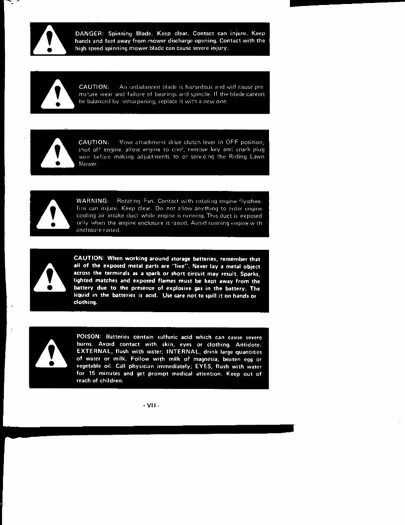
D A N G E R : Spinning Blade. Keep clear. Contact can injure. Keep hands and feet away f rom mower discharge opening. Contac t with the high speed spinning mower blade can cause severe injury.
A C A U T I O N : A n unba lanced blade is hazardous and vj\\\e prema tu re wear and fa i l u re of bearings and sp ind le . If the b lade c a n n o t be balanced by resharpen ing, replace i t w i t h a n e w one .
A C A U T I O N : IVlove a t t a c h m e n t dr ive c l u t c h lever in O F F p o s i t i o n , shu t o f f engine, a l l o w engine t o c o o l , remove key and spark p lug w i re f)efore m a k i n g ad jus tmen ts to or serv c ing the R i d i n g L a w n Mower .
A W A R N I N G : R o t a t i n g Fan, Con tac t w i t h r o t a t i n g engine f l y w h e e l f ins can i n ju re . Keep clear. D o n o t a l l o w a n y t h i n g t o snter engine coo l i ng air i n take d u c t wh i le engine is r u n n i n g . Th is d u c t is exposed on l y when the engine enc losure is raised. A v o i d r u n n i n g engine w i t h enclosure raised.
C A U T I O N : When work ing a round storage batteries, remember that
A all of the exposed metal parts are " l i ve" . Never lay a metal object across the terminals as a spark or short c i rcui t may result. Sparks , l ighted matches and exposed f lames must be kept away f rom the battery due to the presence of explosive gas in the battery. The l iquid in the batteries is acid. Use care not to spill it on hands or clothing.
P O I S O N : Batteries contain sulfuric acid which can cause severe
A burns. A v o i d contact with sk in , eyes or clothing. Ant idote: E X T E R N A L , f lush with water; I N T E R N A L , dr ink large quantities of water or milk. Fo l low with milk of magnesia, beaten egg or vegetable oi l . Call physician immediately; E Y E S , f lush with water for 15 minutes and get prompt medical attention. Keep out of reach of chi ldren.

A D A N G E R : Bat ter ies p roduce exp los ive charges. Keep sparks, f l ame
and cigaret tes away . V e n t i l a t e w h e n charg ing or using in enc losed
space. A l w a y s sh ie ld eyes w h e n w o r k m g near bat ter ies.
A C A U T I O N : Never wear r ings or meta l w a t c h hands w h e n w o r k i n g
w i t h t he t r ac to r e lec t r ica l sys tem or ba t t e r y as y o u m a y g r o u n d a
live c i r c u i t .
W A R N I N G : T o j u m p star t this m t i ch ine :
1. Place travel c o n t r o l lever in neu t ra l , set p a r k i n g b i a k e , and [ ikice movvei (Invfj levet m O F F .
2. Raise eni ime enrdosnie anrl p r o p o(.)en w i t h SLjppoit i o d .
3. Connec t i.u)sitive (Red) ( ' ) j u m p e r cable T ( J b a t t e i y tei mma l n i i stai ter so leno id .
4. Connec t o thet en r tjf [positive ( R e d ! ( + i l u m p e r cai) le (o t fu; posit ive ( 0 l e i m i n a l post of the nooster ba t t e r y .
5. Connec t negat ive i B l a c k ] (-) l u m p e i c.il j le to negat ive (-) t e rm ina l o ! boost',') h a H e i y .
6. Connec t o the i end of nerjative (B lack) [-1 jumper t-iible t o Ihf: on-gme l i l ock . A v o i d c o n n e c t i o n neai \u>-\, cat Inn- j tu i and battel y .
7. S tand on le f t side of mach ine and stai t using i gn i t i on key s w i t c h ,
8. D isconnec t jumper <;at-iles in the ieven,e o i t l e i , tha t is, iL^move the ne(jarii.'e (B lack ) (-) ra l j l e f i ts t . Keej i ends f i o r n l o n c h m g t o p i t ; vent spi i rks.
C A U T I O N : D i i ve a l a sneed s low enough t o insure safety and c o m p l e t i : c o n t i o l at ail i i m f ,
- V I M -

C A U T I O N ; Do n o t v.Tat Inos.-: c l u T h i n q w h i c h m . r y c a t c h i n
C A U T I O N ; 1. Keep all shields in p lace.
2. Before leaving opera to r ' s p o s i t i o n :
a. S h i f t t ransmiss ion t o neut ra l
b. Set p a r k i n g brake
c. Disengage a t t a c h m e n t c l u t c h
d . S h u t o f f eng ine
e. Remove i gn i t i on key
3, Wa i t f o r a l l m o v e m e n t t o s top be fo re serv ic ing mach ine .
4 , Keep people and pets a safe d is tance away f r o m mach ine .
W A R N I N G : B . d m . ' ^•,^l^lllq t ' l iqn:- ' M u d y o f H ' ' a t o i ' s manuu l sa'i-*ty ,vVjVvig,-S. R ' M ' ! ; l •.,!!>•:•, , l l , l > h i l u . O - u l r>i , ,d ' ,M
[ii.'i -^(.ins L^ j r i| & [); j r I n •• :>,iif n l r m 111 o K I n d o i c n|)ci .j 11 n q , S t oi)
(Migini' d n d vvj. I tu i ,i 11 n i c v M i U M i; u i ' - i n n h d " t e d •sniou n 11 n q , Sft
v iC 'Hq, 01 i i i . ik i i ' i " ! j i i y i ' l | i i s i nil • • ! ' i I t '. y n j t : i ' ' , [)ui iS!l i i l , ty ' o ntul-^'
•. I J I k 1 J ti d f ( 11 • I n ni. j I 11 I f II II , r • • • ' 11; •• I r I 11 t i (ii r, (i l l in ,(rh 111' • i •'t J,!' <'' 1.
SI-I ••.'lilt;, . I t ' l l 1 I I I >l IS' •! VH p' 1 ; l lrM ' , 11 K I I -' 11U 1,1 ' ; () 11S O p'' I , (11) I f 7 U I* I I , l i - m.i:' l ) f o h l . i r i ' d P n i n v i u i i u liJine il t ( l e j l i ' i .
A C A U T I O N ; E i ther the en t i re grass ca tcher or the m o w e r discharge chu te guard mus t be m place be fo re y o u opera te t he m o w e r .
- I X -
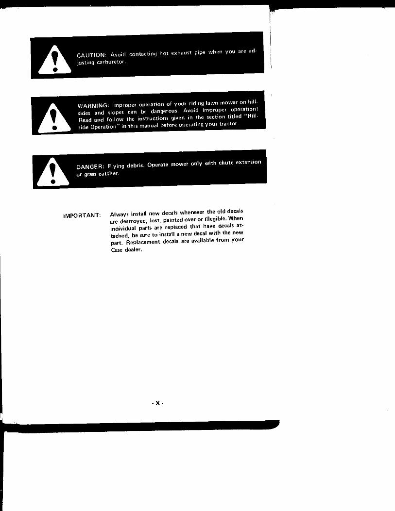
A C A U T I O N : A v o i d c o n t a c t i n g h o t exhaus t p ipe w h e n y o u are adjus t ing ca rbu re to r .
A W A R N I N G : I m p r o p e r o p e r a t i o n o f y o u r r i d i ng l a w n m o w e r o n h i l l sides a n d slopes can be dangerous . A v o i d i m p r o p e r o p e r a t i o n ! Read and f o l l o w the i ns t r uc t i ons g iven in the sect ion t i t l e d " H i l l side O p e r a t i o n " in t h i s manua l be fo re o p e r a t i n g y o u r t r a c t o r .
D A N G E R : F ly ing debris. Operate mower only with chute extension or grass catcher.
I M P O R T A N T : A lways install new decals whenever the old decals are destroyed, lost, painted over or illegible. When individual parts are replaced that have decals attached, be sure to install a new decal wi th the new part. Replacement decals are available f rom y o u r Case dealer.
- X -
HILLSIDE (SLOPE) OPERATIOM
A W A R N I N G : I m p r o p e r o p e r a t i o n o f y o u r r i d i ng l a w n m o w e r o n h i l l sides and slopes can be dangerous. A v o i d i m p r o p e r o p e r a t i o n ! Read and f o l l o w the i ns t r uc t i ons given in the sec t ion t i t l e d " H i t l -side O p e r a t i o n " in th is manua l be fore ope ra t i ng y o u r t r a c t o r .
A v o i d opera t ing r id ing l a w n m o w e r o n h i l ls ides and s lopes. T o m i n i m i z e t h e poss ib i l i t y of accidents wh i l e ope ra t i ng o n hi l ls a n d / o r rough t e r ra i n , obey a c o m b i n a t i o n o f rules, pract ices and good c o m m o n sense.
These i n c l u d e :
1 . Reading, unde rs tand ing , and o b e y i n g all w r i t t e n safety messages appear ing o n decals on the mach ine and in ope ra to r ' s manua ls ,
2. Learning f r o m y o u r opera to r ' s manua l and ca re fu l l y f r o m E X P E R I E N C E h o w t o operate y o u r r id ing l a w n m o w e r c o r r e c t l y . K n o w y o u r r i d i n g l awn m o w e r ' s l i m i t a t i o n s .
3. K n o w i n g the te r ra in o n w h i c h y o u are ope ra t i ng y o u r r i d i n g l a w n m o w e r . The re are te r ra in c o n d i t i o n s o n w h i c h y o u r r i d i n g l awn m o w e r c a n n o t be o p e r a t e d !
4 . Learning t o expec t changes in ope ra t i ng c o n d i t i o n s . A d d i n g or r e m o v i n g a t t a c h m e n t s or we igh t to y o u r r i d m g l awn m o w e r w i l l make y o u r r i d i n g l awn m o w e r p e r f o r m d i f f e ren t l y . Ra in , snow, loose gravel , w e t grass, etc. , change the t rac t i ve c o n d i t i o n s of t h e te r ra in requ i r i ng changes in y o u r ope ra t i ng t e c h n i q u e o r n o t t o opera te o n t h a t terra in .
The f o l l o w i n g paragraphs w i l l cover these pract ices one at a t i m e . Read and s t u d y them. The examples p r o v i d e d are n o t al l inc lus ive b u t w i l l give y o u a f i r m u n d e r s t a n d i n g of the requ i remen ts f o r avo id ing acc idents wh i l e ope ra t i ng y o u r r i d i ng l awn m o w e r .
Case R id ing L a w n Mowers are designed and b u i l t t o c o m p l y w i t h the V o l u n t a r y Standard A N S I B 7 1 . 1 - 1972 and B71 .1a - 1974 ( A m e r i c a n Na t i ona l S tandards I n s t i t u t e ) .
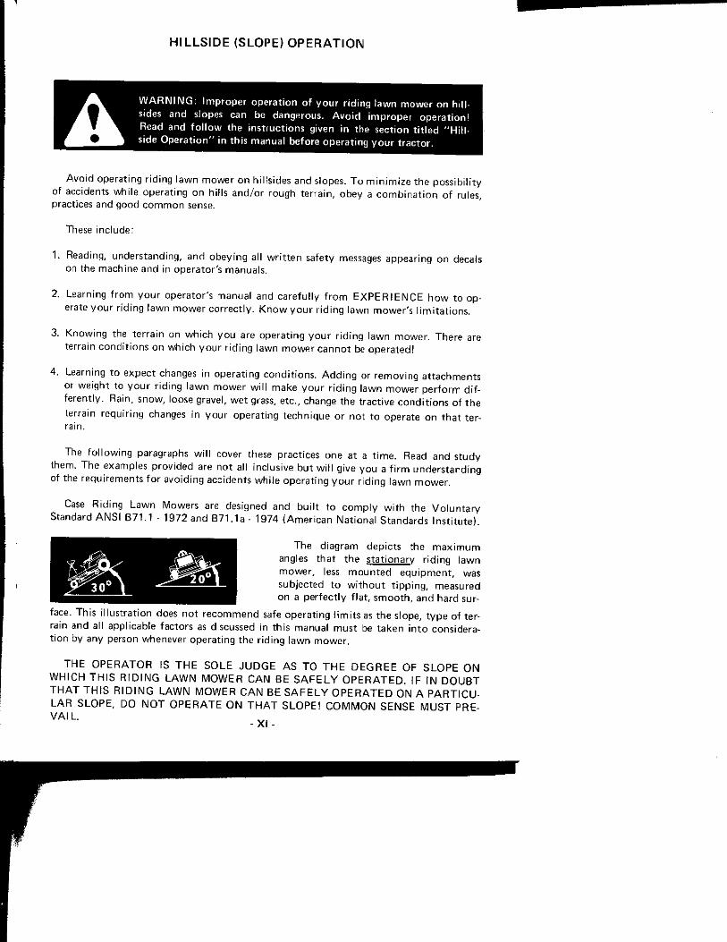
The d iag ram dep i c t s the m a x i m u m angles t h a t t he s t a t i ona ry r i d i n g l a w n m o w e r , less m o u n t e d e q u i p m e n t , was sub jec ted t o w i t h o u t t i p p i n g , measured o n a p e r f e c t l y f l a t , s m o o t h , and ha rd sur
face. Th is i l l us t ra t i on does n o t r e c o m m e n d safe ope ra t i ng l i m i t s as t he s lope, t y p e of terrain and all app l icab le fac to rs as discussed in th is manua l m u s t be t a k e n i n t o cons iderat i o n by any person whenever ope ra t i ng the r i d i ng l a w n m o w e r .
T H E O P E R A T O R IS T H E S O L E J U D G E A S T O T H E D E G R E E O F S L O P E O N W H I C H T H I S R I D I N G L A W N M O W E R C A N B E S A F E L Y O P E R A T E D . I F I N D O U B T T H A T T H I S R I D I N G L A W N M O W E R C A N BE S A F E L Y O P E R A T E D O N A P A R T I C U L A R S L O P E , DO N O T O P E R A T E O N T H A T S L O P E ! C O M M O N S E N S E M U S T PREV A I L

Read. Understand. Obgy:
Safe ty messages are f o u n d o n the r i d i n g l a w n m o w e r and in t he o p e r a t o r ' s manua ls . These m u s t be u n d e r s t o o d by the r i d i n g l awn m o w e r o p e r a t o r t o be o f value. Be sure tha t these messages are s tud ied be fo re s ta r t i ng a n d / o r ope ra t i ng the r i d i n g l a w n m o w e r by an opera to r n o t f a m i l i a r w i t h th is pa r t i cu l a r r i d i n g l a w n m o w e r .
Learn to Operate:
Learn y o u r r i d i ng l a w n m o w e r c o n t r o l s f r o m decals o n the r i d i n g l a w n m o w e r and f r o m ins t ruc t i ons in t he ope ra to r ' s m a n u a l . Pract ice h o w t o p r o p e r l y m a n i p u l a t e these con t ro l s . Pract ice m u s t be done in a f l a t area, clear o f obstac les and bys tanders . Learn y o u r r id ing l a w n mowers ope ra t i ng charac ter is t i cs and l i m i t a t i o n s . These i n c l u d e :
a. a m o u n t o f engine p o w e r avai lab le
b. engine governor response
c. t rac t ive a b i l i t y
d . steer ing character is t ics
e. b rak ing charac ter is t i cs
f. m o v e m e n t o f t ravel lever
g. f o r w a r d and reverse g r o u n d speeds
h . speed of a t t a c h m e n t l i f t
i. and o thers
A t t e m p t i n g any o p e r a t i o n w h i c h approaches or exceeds the r i d i n g l a w n m o w e r ' s l im i
t a t i o n is r i sk ing an acc iden t .
K n o w the Ter ra in :
K n o w the te r ra in o n w h i c h y o u are w o r k i n g . F i n d h i d d e n obstacles by w a l k i n g t h r o u g h and inspec t ing t h e area p r i o r t o o p e r a t i n g y o u r r i d i n g l a w n m o w e r o n i t . Mark obstacles, such as, r ocks , ruts or holes w i t h a 6 f t l o n g po le and red f l a g and stay wel l clear of these obstacles w h e n ope ra t i ng .
Operate y o u r r id ing l a w n m o w e r at a g r o u n d speed s low enough t o insure c o m p l e t e c o n t r o l at al l t imes.
Regulate the t ravel c o n t r o l lever s l ow l y and s m o o t h l y t o m a i n t a i n th is safe speed.
A lways dr ive in a f o r w a r d d i r e c t i o n w h e n p roceed ing d o w n h i l l . Never d r ive u p a h i l l , I f necessary, back u p a h i l l t o t he desi red p o s i t i o n . A l w a y s back u p load ing ramps and t i l t bed trai lers. I f necessary t o t u r n w h i l e o n a h i l l , a lways t u r n d o w n w a r d .
- XM -
Y o u r j udgemen t , based o n ope ra t i ng exper ience is t he f ina l w o r d in dec id ing if y o u shou ld negot ia te any g iven h i l l o r s lope. I f y o u are in d o u b t a b o u t sa fe ty , S T A Y O F F T H E S L O P E .
Under no c i rcumstances shou ld an inexper ienced o p e r a t o r a t t e m p t t o use y o u r r i d i n g lawn m o w e r o n slopes or h i l ls ides.
Y o u may encoun te r some te r ra in o n w h i c h y o u r r i d i n g l awn m o w e r c a n n o t be operated even i f a d i f f e r e n t p iece of e q u i p m e n t has ope ra ted the re in t he past.
Learn to Compensate for Changes in Operating Condi t ions:
A d d i n g or r emov ing a t t a c h m e n t s (such as bagging a t t a c h m e n t ) change the w e i g h t and we igh t d i s t r i b u t i o n o f y o u r r i d i n g l a w n m o w e r a n d , t h e r e f o r e , change y o u r r i d i ng l awn m o w e r ' s ope ra t i ng character is t ics .
Be alert t o these changes. Pract ice ope ra t i ng the r i d i n g l awn m o w e r af ter each change has been made.
A d d i n g an a t t a c h m e n t (we igh t ) t o the rear of t he r i d i ng l a w n m o w e r reduces the we igh t o n the f r o n t ax le .
T rac t ive c o n d i t i o n s w i l l vary w i t h wea the r and te r ra in and e q u i p m e n t .
Areas wet w i t h d e w or ra in w i l l be more s l ippery t h a n w h e n d r y . Areas covered w i t h
loose gravel are more s l ippery t h a n f i r m d r y g r o u n d . Greater s t o p p i n g d is tances are re
q u i r e d in these s l ippery areas.
Sp inn ing rear wheels t e n d to m o v e the r i d i ng l awn m o w e r s ideways.
The f ina l w o r d in safe r i d i ng l a w n m o w e r o p e r a t i o n rests on y o u r j u d g e m e n t .
I f in d o u b t o f y o u r sa fe ty , S T A Y O F F T H E S L O P E .
- X I I I -

TO THE PURCHASER OF A CASE RIDING LAWN MOWER
The care y o u give y o u r n e w Case R id i ng Lawn M o w e r w i l l great ly d e t e r m i n e the satisf a c t i o n and service l i f e y o u w i l l o b t a i n f r o m i t . Use th is m a n u a l as y o u r gu ide . B y observ ing the i ns t ruc t i ons and suggest ions in th is m a n u a l , y o u r Case R id i ng L a w n M o w e r w i l l serve y o u we l l f o r m a n y years.
As an A u t h o r i z e d Case Dealer , we s tock G e n u i n e Case Parts, w h i c h are m a n u f a c t u r e d w i t h the same p rec is ion and sk i l l s as t h e o r i g i na l e q u i p m e n t . O u r f a c t o r y t r a i n e d staf f is k e p t we l l i n f o r m e d o n the best m e t h o d s o f se rv ic ing Case e q u i p m e n t and is ready and able t o he lp y o u .
S h o u l d y o u requ i re a d d i t i o n a l aid o r i n f o r m a t i o n , c o n t a c t us.
Laws o f some states o r p rov inces m a y requ i re t ha t th is u n i t be e q u i p p e d w i t h a S P A R K A R R E S T O R O R S P A R K A R R E S T I N G M U F F L E R , T h e S ta te o f C a l i f o r n i a , as an e x a m p l e , is one state w h i c h has such regu la t i ons f o r ag r i cu l t u ra l and f o r e s t r y a p p l i c a t i o n s , p lus a regu la t i on f o r c o n s t r u c t i o n a p p l i c a t i o n s in f o res t - cove red , b rush -covered , or grass-covered lands.
T y p i c a l l y such laws and regu la t ions requ i re spark ar res t ing devices t o be m a i n t a i n e d in good w o r k i n g o rde r and t y p i c a l l y t o be a t t ached t o t he exhaus t sys tem o f na tu ra l l y asp i ra ted engines (engines w i t h o u t a t u r b o charger ) .
The Canadian G o v e r n m e n t , under a u t h o r i t y g ran ted b y the Rad io A c t , has p r o m u l g a t e d regulat ions cover ing th is gasol ine p o w e r e d Case R id i ng L a w n M o w e r if i m p o r t e d i n t o Canada o n or af ter Sep tember 1, 1976 .
The spark p lug(s) i n th is m a c h i n e w h e n rep laced m u s t have a res is tor t y p e spark p l u g ins ta l led .
The c e r t i f i c a t i o n label app l i ed t o t he eng ine m u s t n o t be r e m o v e d or o b l i t e r a t e d .
3 -80 -SL-800 U. S. Price $ 1 . 4 0 P R I N T E D I N U.S .A .
N O T I C E
C A N A D I A N R A D I O I N T E R F E R E N C E R E G U L A T I O N S
• 2 -
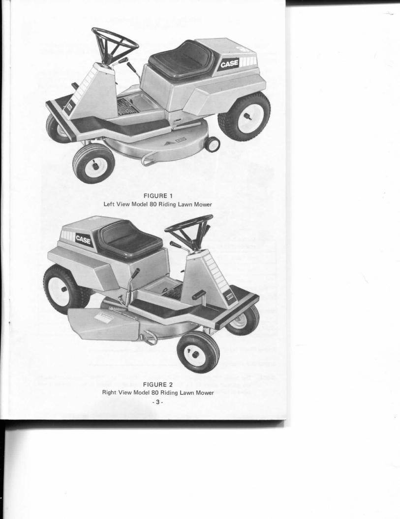
F I G U R E 1
Le f t V i e w Mode l 8 0 R id i ng L a w n M o w e r
\
F I G U R E 2
R igh t V i e w Mode l 8 0 R id i ng L a w n M o w e r
- 3 -
r
SERIAL NUMBER
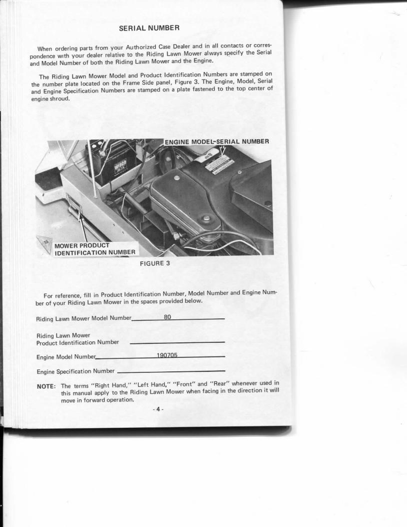
When o rde r i ng par ts f r o m y o u r A u t h o r i z e d Case Dealer and in all c o n t a c t s or correspondence w i t h y o u r dealer re la t ive t o the R id ing L a w n M o w e r a lways spec i f y t he Serial and Model N u m b e r o f b o t h the R id i ng L a w n M o w e r and the Eng ine .
T h e R id ing L a w n M o w e r Mode l and P r o d u c t I d e n t i f i c a t i o n N u m b e r s are s tamped o n the number p la te loca ted on the F rame Side pane l , F igure 3. T h e Eng ine , M o d e l , Serial and Engine Spec i f i ca t i on N u m b e r s are s tamped o n a p la te fas tened t o t he t o p cen te r o f engine s h r o u d .
F I G U R E 3
For re ference, f i l l in P r o d u c t I d e n t i f i c a t i o n N u m b e r , Mode l N u m b e r and Eng ine Number o f y o u r R id i ng L a w n M o w e r in t he spaces p r o v i d e d b e l o w .
R id ing L a w n M o w e r Mode l N u m b e r 8 0
R id ing Lavi/n M o w e r
Produc t I d e n t i f i c a t i o n N u m b e r .
Engine Model N u m b e r l ^ Q Z i l S
Engine Spec i f i ca t i on N u m b e r
N O T E : The te rms " R i g h t H a n d , " " L e f t H a n d , " " F r o n t " and " R e a r " wheneve r used i n th is manua l app ly t o the R i d i n g L a w n M o w e r w h e n fac ing in the d i r e c t i o n i t w i l l move in f o r w a r d o p e r a t i o n .
- 4 -
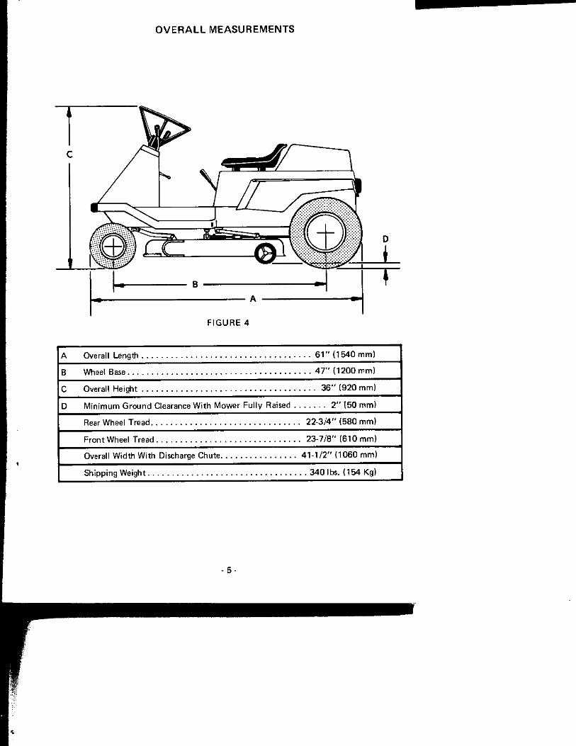
O V E R A L L MEASUREMENTS
C
F I G U R E 4
A Overal l Length 6 1 " ( 1 5 4 0 m m )
B Wheel Base 4 7 " { 1 2 0 0 m m )
C Overal l He igh t 3 6 " ( 9 2 0 m m )
D M i n i m u m G r o u n d Clearance W i t h M o w e r F u l l y Raised 2 " ( 5 0 m m )
Rear W h e e l T r e a d 2 2 - 3 / 4 " ( 5 8 0 m m )
F r o n t Wheel Tread 2 3 - 7 / 8 " ( 6 1 0 m m )
Overal l W i d t h W i t h Discharge Chu te 4 1 - 1 / 2 " ( 1 0 6 0 m m )
Sh ipp i ng We igh t 3 4 0 l b s . ( 1 5 4 Kg)
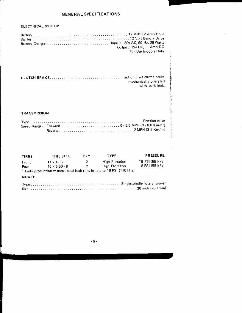
GENERAL SPECIFICATIONS
E L E C T R I C A L S Y S T E M
Bat te ry Star ter Ba t te ry Charger
12 V o l t 12 A m p H o u r 12 V o l t Bend i x D r i ve
I n p u t : 120v A C , 6 0 Hz , 25 W a t t s O u t p u t : 12v D C , 1 A m p D C
For Use Indoo rs O n l y
C L U T C H B R A K E F r i c t i o n dr ive c l u t c h - b r a k e mechan i ca l l y ope ra ted
w i t h park l o c k .
T R A N S M I S S I O N
F r i c t i o n dr ive 0 - 5 . 5 M P H ( 0 - 8 . 8 K m / h r )
2 M P H (3 .2 K m / h r ) Speed Range - - F o r w a r d
Reverse .
T I R E S T I R E S I Z E P L Y T Y P E P R E S S U R E
F r o n t 1 1 x 4 - 5 2 High F l o t a t i o n * 8 PSI (55 kPa) Rear 16 x 6 . 5 0 - 8 2 High F l o t a t i o n 8 PSI (55 kPa) * Ear ly p r o d u c t i o n w i t h o u t bead- lock r ims i n f l a te t o 18 PSI ( 1 1 0 kPa)
M O W E R
T y p e S ing lesp ind le r o t a r y m o w e r
Size . 3 0 inch ( 7 6 0 m m )
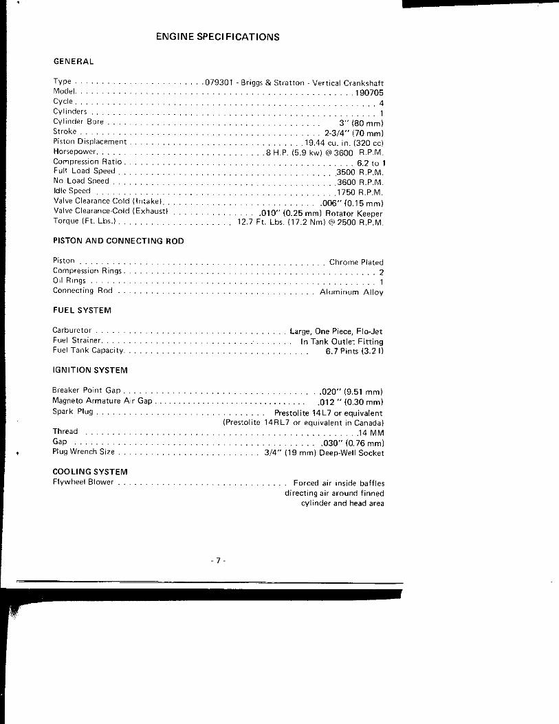
ENGINE SPECIFICATIONS
G E N E R A L
Type 0 7 9 3 0 1 - Briggs & S t r a t t o n - Ver t i ca l C ranksha f t Mode l 1 9 0 7 0 5 Cycte 4 Cy l inders 1 Cy l inder Bore 3 " (80 m m ) Stroke 2 - 3 / 4 " (70 m m ) Piston D isp lacement 19.44 cu . i n . ( 3 2 0 cc) Horsepower 8 H.P. (5.9 kw) @ 3 6 0 0 R.P.M. Compression Ra t i o 6,2 t o 1 Ful l Load Speed 3 5 0 0 R.P.M. No Load Speed 3 6 0 0 R.P.M. Idle Speed 1750 R.P.M. Valve Clearance-Cold ( I n t ake ) 0 0 6 " ( 0 . 15 m m ) Valve Clearance-Cold (Exhaus t ) 0 1 0 " ( 0 . 2 5 m m ) R o t a t o r Keeper Torque (F t . Lbs.) 12.7 F t . Lbs. ( 1 7 . 2 N m ) (9) 2 5 0 0 R.P.M.
P ISTON A N D C O N N E C T I N G R O D
Piston C h r o m e Plated Compression Rings 2 Oil Rings 1 Connec t ing Rod A l u m i n u m A l l o y
F U E L S Y S T E M
Carbure to r Large, One Piece, F lo -Je t Fuel Stra iner In Tank O u t l e t F i t t i n g
Fuel T a n k Capac i ty 6 .7 Pints (3 .2 I)
I G N I T I O N S Y S T E M
Breaker Po in t Gap . 0 2 0 " (9 .51 m m ) Magneto A r m a t u r e A i r Gap . 0 1 2 " ( 0 . 30 m m ) Spark Plug Pres to l i te 1 4 L 7 o r equ i va len t
(Presto l i te 1 4 R L 7 or equ iva len t in Canada) Thread 14 M M Gap 0 3 0 " ( 0 , 76 m m ) Plug Wrench Size 3 / 4 " (19 m m ) Deep-Wel l Socke t
C O O L I N G S Y S T E M F lywhee l B lower Forced air inside baf f les
d i r e c t i n g air a r o u n d f i n n e d cy l i nde r and head area

FUEL SPECIFICATIONS
C A R B U R E T I O N O N S M A L L G A S O L I N E E N G I N E S IS A L W A Y S C R I T I C A L O F D I R T . IT IS R E C O M M E N D E D T H A T A F I L T E R I N G F U E L F U N N E L A L W A Y S BE U S E D A L O N G W I T H C L E A N G A S O L I N E .
A T A N Y E V I D E N C E O F F U E L S T A R V A T I O N , C L E A N T H E F I L T E R I N T H E T A N K O U T L E T F I T T I N G .
D O N O T M I X O I L W I T H G A S O L I N E F O R T H I S E N G I N E .
F I G U R E 5
C A U T I O N : Never s tore the e q u i p m e n t w i t h gasol ine in t he tank inside a b u i l d i n g where fumes m a y reach an o p e n f l a m e or spark. A l l o w the engine t o coo l be fore s t o r i ng in any enc losure .

G A S O L I N E
The typ ica l Octane n u m b e r rat ings fo r regular grade gasol ine (March 1 9 6 7 ) .
M o t o r M e t h o d 8 6 . 2 Oc tane N u m b e r Research M e t h o d 9 4 . 2 Oc tane N u m b e r Average 9 0 . 2 Octane N u m b e r
These t w o Octane rat ings are used t o de f i ne the a n t i - k n o c k q u a l i t y o f gasol ine. I t has become c o m m o n pract ice in the P e t r o l e u m I n d u s t r y t o refer o n l y t o the R E S E A R C H M E T H O D R A T I N G a l t hough in the U n i t e d States the average of the t w o f igures is pos ted on gasoline pumps .
When on l y one Octane ra t ing is given f o r gasol ine and the ra t ing m e t h o d is n o t speci f ied, i t can be assumed t o be the average ra t ing in t he U n i t e d States or t he Research M e t h o d Ra t ing elsewhere i n t he W o r l d .
Engines used in Case R i d i n g L a w n Mowers are des igned t o operate o n R E G U L A R G R A D E gasol ine hav ing a m i n i m u m research m e t h o d ra t ing o f 9 0 . 7 Oc tane . Th is w i l l give fu l l power and e c o n o m y toge the r w i t h long eng ine l i fe and l o w ma in tenance cos t .
Non- leaded gas is a su i tab le a l te rna t i ve f o r use in all 4 -cyc le air coo led engines used o n Case R id ing L a w n Mowers p r o v i d e d the Average Octane Ra t ing in t he U n i t e d States and the Research M e t h o d Octane Ra t ing e lsewhere in t he W o r l d is 90 or h igher .
C A U T I O N : Hanf l lc gasol ine w i t h car.' i t is h igh l y f l a m m a b l e .
a. Use approved gasol ine co t i ta ine r .
b. Never r emove the cap of the fue l tank or add gasol ine to a r u n n i n g or h o t eng ine, or f i l l the fuel t a n k i ndoo rs . Wir ie up sp i l led gasol ine.
c. 0 [ )en doors if the engine is r u n in the garage — exhaus t fumes aie dangerous . Do no t r u n the eng ne' ( m o t o r ) indoors .
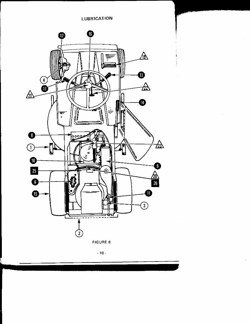

L U B E C H A R T
_8
10 11 12 13 14 15 16 17
19
20 21 22 23
25 26
S E R V I C E P O I N T S
An t i -Sca lp ing Wheels
Engine Coo l i ng A i r In take Screen
Engine Oi l
F ron t Spindles ( k i ng pins)
A i r Cleaner
A i r Leaks
Bat tery
Chain and Chain B racke t P ivo t
Drive Bel ts
Engine Oi l
F r o n t Wheel Bearings
Mower Dr ive C lu t ch
Mower Height A d j u s t Lever Pivot Points
Rear A x l e Bearinas
Steer ing C o l u m n
Travel C o n t r o l
C lu tch Brake L inkage
Spark P l u g °
Steer ing Gear
T h r o t t l e and Choke C o n t r o l
Transmiss ion P ivot S u p p o r t Plate
Engine Coo l ing Fins
Spark Plug
F R E Q U E N C Y
H O U R S O R
M O N T H L Y
H O U R S O R Y E A R L Y
A l w a y s check engine o i l level be fo re each use o f R i d i n g M o w e r . Keep oi l level t o
the f u l l m a r k on the d i p s t i ck . See page 12 f o r eng ine l u b r i c a t i o n r e c o m m e n d a t i o n s .
' * Be sure there are n o leaks be tween gaskets, j o i n t s at c a r b u r e t o r , air c leaner and
cy l i nde r b l ock .
More o f t e n in dus ty c o n d i t i o n s . Remove s h r o u d t o c lean,
o Clean and regap.
Use n u m b e r 1 gun grease ( L i t h i u m Base) f o r atl pressure f i t t i ngs (as m a n y s t rokes as requ i red ) .
- n -

E N G I N E L U B R I C A T I O N
S E L E C T I O N O F O I L
I t is e x t r e m e l y i m p o r t a n t t h a t y o u select and use in y o u r Case R i d i n g L a w n M o w e r Engine a de te rgen t t y p e , h igh q u a l i t y , SD or SC API Service C lass i f i ca t ion O i l .
A l w a y s check engine o i l level be fo re each use of R i d i n g L a w n M o w e r or every 5 hou rs o f o p e r a t i o n , wh ichever occurs f i r s t .
O I L S A E V I S C O S I T Y R A T I N G
A i r Tempera tu res
S A E 30 40°F {2°C) and A b o v e
S A E 5W-20 o r 5W-30 be tween 40°F (2°C) and 0 °F ( -18°C)
S A E low o r 10W-30 B e l o w 0 °F ( -18°C) d i l u t e d 10% w i t h Kerosene
O I L C H A N G E
Dra in and ref i l l the crankcase a f te r the f i r s t 5 hours o f o p e r a t i o n , and every 2 5 hou rs o f o p e r a t i o n the rea f te r . Check o i l level da i l y and keep level t o t he f u l l m a r k o n t h e d i p s t i ck .
If possib le, run engine jus t p r i o r t o chang ing o i l -- t he o i l w i l l f l o w m o r e f ree ly and car ry away a greater a m o u n t o f c o n t a m i n a n t w h e n h o t .
I f the engine service is severe - { f r equen t s t o p p i n g and s t a r t i ng , h igh or l o w opera t ing t empe ra tu re ) - the crankcase shou ld be d ra ined m o r e o f t e n t o p revent the f o r m a t i o n of sludge or h a r m f u l depos i ts in the engine.
A C A U T I O N ; Disengage p o w e r t o a t l a c h m e n t ( s ) and s t o p the engine ( m o t o r ) be fo re m a k i n g any repairs o r ad jus tmen ts .
I M P O R T A N T : 1 . W h e n the crankcase is d ra i ned , re f i l l w i t h 2 -1 /4 measured p in ts (1 .0 1} o f o i l .
2. Opera te the eng ine f o r a f e w m i n u t e s , a l l o w s u f f i c i e n t t i m e f o r the o i l t o r u n d o w n o f f t he eng ine par ts . T h e n check the o i l level w i t h t he d i p s t i c k .
3 . Th is w i l l p reven t o v e r f i l l i n g or u n d e r f i l l i n g t he c rankcase, e i t he r o f w h i c h can be d e t r i m e n t a l t o t he engine service l i fe and w i l l give y o u false o i l c o n s u m p t i o n records .
- 1 2 -

OPERATING INSTRUCTIONS
O P E R A T I N G C O N T R O L S
I M P O R T A N T : Th is Riding Lawn Mower is equipped with N E U T R A L S T A R T S W I T C H E S .
A . Lawn Mowers prior to S / N 9 7 4 6 0 9 8
The engine cannot be started unless the travel control lever is in neutral and the mower drive lever* is in the " O F F " posit ion.
B. L a w n Mowers S / N 9 7 4 6 0 9 8 and after
The engine cannot be started unless the clutch-brake pedal is depressed and the mower drive lever" is in the " O F F " posit ion. Release pedal s lowly after engine starts.
* T h e engine may not start when the mower is In the lowest cutt ing posit ion. Raise the mower or pull the mower drive lever toward the " O F F " position to al low the engine to s t a r t
1. I G N I T I O N K E Y A N D S T A R T E R S W I T C H - T u r n key all the way to the right until starter engages to start the engine. When stopping the engine, turn the key to the left " O f f " posit ion. Be sure the mower drive lever. Reference 7 is in the " O f f " position and travel control lever. Reference 5, is in " N e u t r a l " before starting or stopping the engine.
2. C H O K E A N D T H R O T T L E - When starting a cold engine, position the lever all the way to the " C h o k e " posit ion. Move the lever f rom the choke posit ion immediately after the engine begins to run. Choking may not be necessary when restarting a warm engine. Start with the lever in the " S l o w " posit ion. Exper ience will soon tell you how much choking is necessary for different starting condit ions.
F I G U R E 8
- 1 3 -
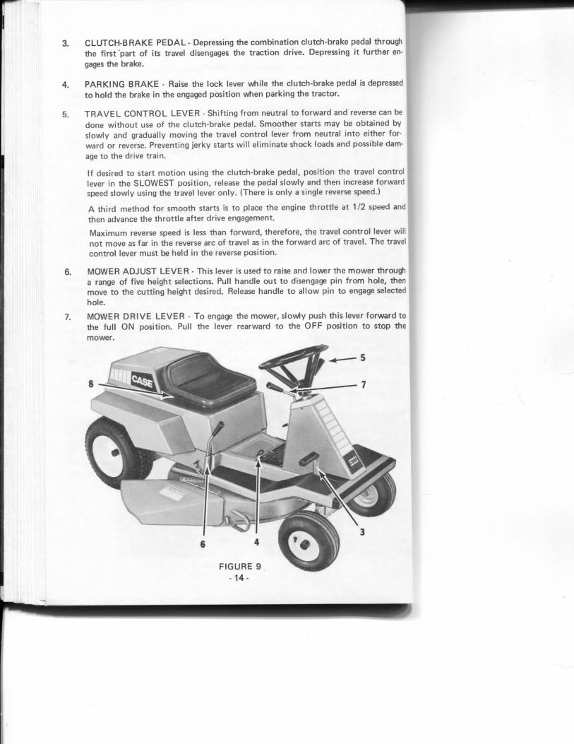
3. C L U T C H - B R A K E P E D A L - Depressing the combinat ion clutch-brake pedal through the first "part of its travel disengages the traction drive. Depressing it further engages the brake.
4. P A R K I N G B R A K E - Raise the lock lever while the c lutch-brake pedal is depressed to hold the brake in the engaged position when parking the tractor.
5. T R A V E L C O N T R O L L E V E R - Shift ing from neutral to forward and reverse can be done without use of the clutch-brake pedal. Smoother starts may be obtained by slowly and gradually moving the travel control lever from neutral into either forward or reverse. Preventing jerky starts will el iminate shock loads and possible damage to the drive train.
If desired to start mot ion using the clutch-brake pedal, position the travel control lever in the S L O W E S T posit ion, release the pedal s lowly and then increase forward speed slowly using the travel lever only . {There is only a single reverse speed.)
A third method for smooth starts is to place the engine throttle at 1/2 speed and then advance the throttle after drive engagement.
Maximum reverse speed is less than forward, therefore, the travel contro l lever will not move as far in the reverse arc of travel as in the forward arc of travel. T h e travel control lever must be held in the reverse position.
6. M O W E R A D J U S T L E V E R - Th is lever is used to raise and lower the m o w e r through a range of five height selections. Pull handle out to disengage pin f rom hole, then move to the cutt ing height desired. Release handle to a l low pin to engage selected hole.
7. M O W E R D R I V E L E V E R - T o engage the mower , s lowly push this lever forward to the full O N posit ion. Pull the lever rearward to the O F F posit ion to stop the mower.

I M P O R T A N T : T o increase dr ive be l t l i fe , engage a t t a c h m e n t Dr i ve Lever at s l o w engine speed and also before e n c o u n t e r i n g heavy grass.
8. S E A T A D J U S T M E N T - Three sets of m o u n t i n g holes are p r o v i d e d in t he seat supp o r t . Select the seat p o s i t i o n w h i c h gives the m a x i m u m c o m f o r t w i t h y o u r hands
ho ld i ng the steer ing wheel and y o u r f ee t o n the f o o t rests. T o change p o s i t i o n l i f t the engine enc losure and remove the f o u r capscrews, re locate seat and re ins ta l l cap-screws and lockwashers .
P R E - S T A R T I N G C H E C K L I S T
Before s ta r t i ng y o u r n e w Case R i d i n g Lawn M o w e r f o r t he f i r s t t i m e and be fo re each operat ing pe r iod the rea f te r , check the f o l l o w i n g .
L Make sure everyone responsib le f o r tfie m o w e r ' s o p e r a t i o n and m a i n t e n a n c e under stands the i m p o r t a n c e o f c lean f u e l , o i ls , con ta ine rs a n d funne ls .
2. Check t h a t all l u b r i c a t i n g f i t t i n g s are serv iced as d i r ec ted in t he L u b r i c a t i o n Char t .
3. Check engine oi l level and add as necessary.
4 . Be sure t h a t air c leaner, and b l o w e r air i n t ake screen on eng ine are f ree o f obs t ruc t i ons and excessive d i r t .
5. Check t h a t the fue l t a n k is f i l l e d w i t h c lean f u e l t h a t meets r equ i r emen ts l i s ted under Fuel Spec i f i ca t i ons . A l w a y s w ipe fue l t ank cap clean before r e m o v i n g i t . Be sure ven t ho le in fue l t a n k cap is open .
6. Check all ope ra t i ng c o n t r o l s f o r p rope r f u n c t i o n .
A Become Thorough ly fdmi l i a i w i t h all i i d i n g lawn m o w e i control ' " . i)e-f oi e 0[ ie i a l ing .
R U N IN P R O C E D U R E
Your new R id i ng Lawn Mower s h o u l d be sub jec ted t o a run in p e r i o d b e f o r e i t is op erated at fu l l l oad . Dr ive i t f o r a p p r o x i m a t e l y an h o u r t o get t he feel of o p e r a t i o n . S h i f t the t ravel c o n t r o l lever t h r o u g h i ts f u l l range o f f o r w a r d t ravel and reverse d u r i n g t h e r u n in pe r i od ,
M O U N T I N G A N D D I S - M O U N T I N G T H E R I D I N G L A W N M O W E R
M o u n t the m o w e r f r o m the l e f t s ide, s ta r t i ng w i t h y o u r l e f t f o o t on the l e f t f o o t rest, your l e f t hand on s teer ing wheel and r i gh t h a n d o n seat back. T h e n sw ing y o u r r i gh t f o o t through be tween steer ing whee l and seat.
D ismoun t using the reverse o f the above p rocedu re .
- 1 5 -

STARTrNG PROCEDURE
1. For L a w n Mowers prior to S / N 9 7 4 6 0 9 8 , place the travel control lever in neutral and the mower drive lever in the " O F F " posit ion.
For L a w n Mowers S / N 9 7 4 6 0 9 8 and after, place in neutral , depress the clutch-brake pedal and place the mower drive lever in the " O F F " posit ion.
* T h e engine may not start when the mower is in the lowest cutt ing posit ion. Raise the mower or pull the mower drive lever toward the " O F F " posit ion to a l low the engine to start.
2. Position the Choke Thrott le Lever all the way to the " C h o k e " posit ion if the engine is co ld . If engine is warm, leave the lever set at the " S l o w " posit ion. Exper ience will quickly tell y o u which lever setting to use under various temperature condit ions.
F I G U R E 10
- 1 6 -
3. T u r n the I gn i t i on K e y al l the w a y t o t he r i gh t t o s tar t the eng ine.
I M P O R T A N T : In the event o f a " fa lse s t a r t , " t ha t is, i f the engine gets up su f f i c i en t speed t o disengage the s tar ter b u t fa i ls t o c o n t i n u e r u n n i n g , the engine mus t be a l l owed t o c o m e t o a c o m p l e t e ha l t be fo re a restar t a t t e m p t is made. I f the f l y w h e e l is s t i l l r o t a t i n g when the sw i t ch is engaged, t he f l y w h e e l and s tar ter gears w i l l clash and c o u l d be damaged .
C rank i ng t i m e m u s t be l i m i t e d t o 3 0 seconds f o l l o w e d by a 60 second coo l i ng pe r iod t o p revent ove rhea t ing o f the s ta r t i ng m o t o r . I f an eng ine fai ls t o s tar t a f te r this l eng th o f t i m e , i gn i t i on or c a r b u r e t i o n t r oub les are i nd i ca ted and shou ld be co r rec ted before the engine is p laced in o p e r a t i o n .
4. A f t e r the engine starts and runs , move the lever o u t o f the c h o k e p o s i t i o n .
I M P O R T A N T : D o n o t a t t e m p t t o s tar t m o w e r by push ing or t o w i n g as ser ious damage t o the dr ive sys tem m a y resu l t .
5. A l w a y s a l l o w the engine t o " w a r m - u p " f o r a f ew m i n u t e s be fo re ope ra t i ng unde r l oad .
A C A U T I O N : Disenciaye all a t t a c h m e n t c lu tches and sh i f t i n to neut ra l be fore a t t e m p t i n g to s tar t the engine ( m o t o r ) .
W A R N I N G : I m p r o p e r o p e r a t i o n of y o u r r id ing l a w n m o w e r o n h i l l sides and slopes can be dangerous. A v o i d i m p r o p e r o p e r a t i o n ! Read a n d f o l l o w the i ns t ruc t i ons g iven in the sect ion t i t l e d " H i l l side O p e r a t i o n " in th is manua l be fo re o p e r a t i n g y o u r t r a c t o r .
S T O P P I N G T H E E N G I N E
1. A n engine t h a t has been w o r k i n g u n d e r l oad s h o u l d id le f o r a f e w m i n u t e s so the engine par ts can coo l even ly be fo re i t is shu t o f f .
2. Place all ope ra t i ng c o n t r o l s i n n e u t r a l .
3. T u r n i g n i t i o n key t o t he " O F F " or u p r i g h t p o s i t i o n .
A C A U T I O N : A l w a y s shut o f f engine, remov( ; key , set pa rk i ng brake, and wai t u n t i l al l engine and m o w e r m o t i o n has s topped before d i s m o u n t i n g f r o m the o p e r a l o i ' s seal .
- 17 -
L A W N MOWl N G
1. Operate engine a t approxinr^ately 3/4 t o f u l l t h r o t t l e a n d regula te the Trave l Con t ro l Lever acco rd ing t o m o w i n g c o n d i t i o n s . As a genera! r u l e , set the t h r o t t l e as l o w as pract ica l t o o b t a i n m a x i m u m f u e l e c o n o m y b u t h igh enough t o avo id eng ine lug d o w n or l abo r w h i c h c o u l d cause ove rhea t ing and p o o r m o w i n g p e r f o r m a n c e . Unless grass is unusua l l y l i gh t , a lways opera te i n " L o w " speed range.
2. If grass is heavy and h igher t h a n n o r m a l , resul ts can be i m p r o v e d by m o w i n g twice. Make the f i r s t c u t w i t h t he m o w e r set h igher t han n o r m a l ; t h e n repeat w i t h the m o w e r set at desi red f i n i s h e d c u t he igh t . W h e n m o w i n g heavy grass, a lways discharge c l i pp ings away f r o m the u n c u t area.
A W A R N I N G : B f sute tha t the muvvei i l n v e levi.'i is o f f , the encMiie is shLJt o f f , the key removed and the bUide lias s topped sp inn in i i I te fo ie a t t e m p t r i f ) t o clean a pk igqed dischai chu te .
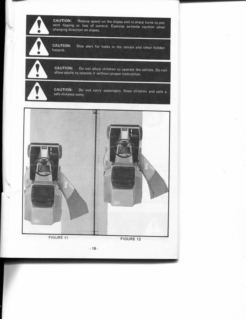
3. Figures 11 and 12 i l l us t ra te t w o systems f o r m o w i n g . I f t he grass is h igh or heavy, a lways m o w t o t h r o w t h e c l i pp ings away f r o m the u n c u t area. F igure 12 . I f the grass is l i gh t and m o r e t h o r o u g h m u l c h i n g is des i red , discharge tiie c l i pp ings toward the cen te r o f t he u n c u t area. F igure 11. W h e n m o w i n g in th is manner , a f i na l strip of m u l c h e d c l i pp ings a b o u t th ree t o f o u r f ee t w ide w i l l rema in near t h e center of the t a w n . Th is can be easi ly s w e p t up t o leave a wel l g r o o m e d appearance.
4. T r i m m i n g w i l l be neater and c loser b y us ing t h e l e f t side of t he m o w e r since the c l i pp ings w i l l be d ischarged away f r o m t h e ob jec t . A l s o the safe ty sh ie ld over the discharge open ing prevents m o w i n g as close t o ob jec ts .
5. A l w a y s engage r i d i n g m o w e r and m o w e r d r ive systems s m o o t h l y .
A Be ce i t a in whoever operates the m o w e r has read and unders tands the safety rules in th is m a n u a l .
A Remember , a care fu l ope ra to r is a lways the best insurance against an acc ident . Give c o m p l e t e and u n d i v i d e d a t t e n t i o n t o the j o b at h a n d .
A C A U T I O N : Clear the w o r k area of ob jec ts w h i c h m i g h t he p i c ked up and t h r o w n .
18-
E E E
C A U T I O N ; Reduce speed o n the slopes and in sharp t u rns t o preven t t i p p i n g or loss of c o n t r o l . Exerc ise e x t r e m e c a u t i o n w h e n chang ing d i r e c t i o n o n slopes.
C A U T I O N : Stay a ler t fo r holes in the te r ra in and o t h e r h i d d e n hazards. ^
C A U T I O N : D o n o t a l l o w c h i l d r e n t o opera te the veh ic le . D o n o t a l l o w adu l t s t o opera te i t w i t h o u t p r o p e r i n s t r u c t i o n .
C A U T I O N : D o n o t ca r r y passengers. Keep c h i l d r e n and pets a safe d is tance away . ;
F I G U R E 11 F I G U R E 12
- 19
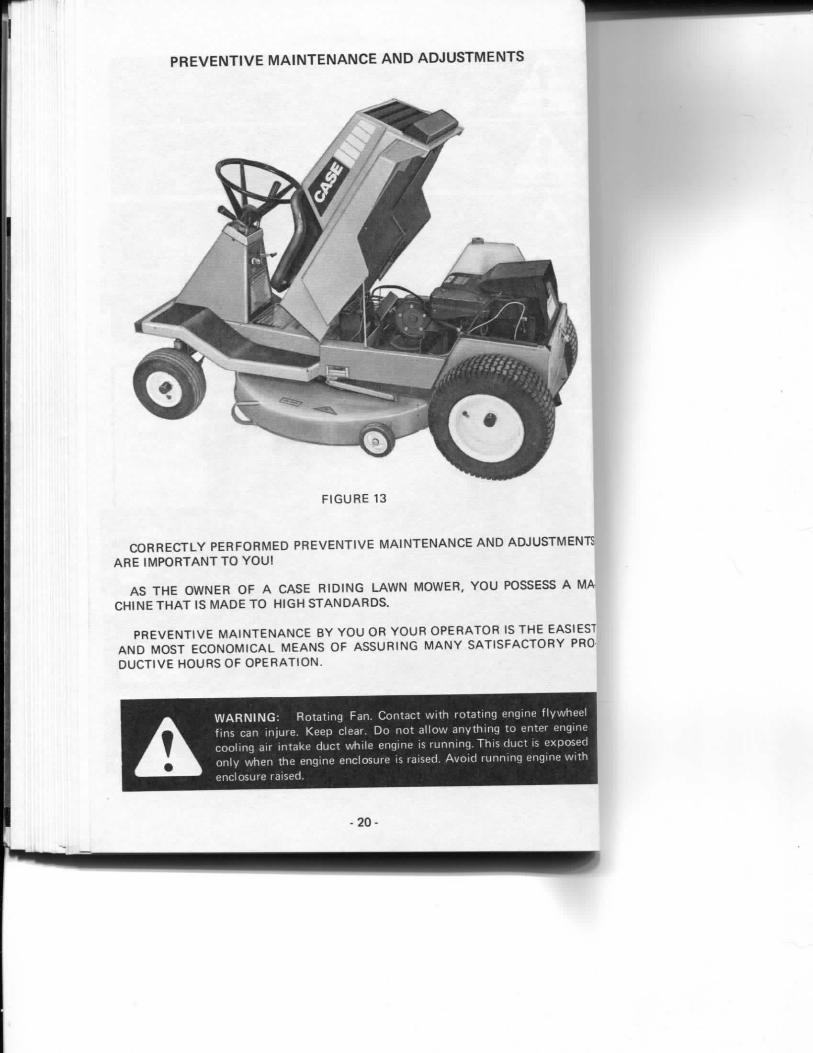
PREVENTIVE MAINTENANCE AND ADJUSTMENTS
F I G U R E 13
C O R R E C T L Y P E R F O R M E D P R E V E N T I V E M A I N T E N A N C E A N D A D J U S T M E N T S A R E I M P O R T A N T T O Y O U !
AS T H E O W N E R O F A C A S E R I D I N G L A W N M O W E R . Y O U POSSESS A M A C H I N E T H A T IS M A D E T O H I G H S T A N D A R D S . |
P R E V E N T I V E M A I N T E N A N C E B Y Y O U O R Y O U R O P E R A T O R IS T H E EASIEST A N D M O S T E C O N O M I C A L M E A N S O F A S S U R I N G M A N Y S A T I S F A C T O R Y PRO D U C T I V E H O U R S O F O P E R A T I O N .
A W A R N I N G : R o t a t i n g Fan. C o n t a c t w i t h r o t a t i n g eng ine f l y w h e e l f ins can i n ju re . Keep clear. D o n o t a l l o w a n y t h i n g t o enter engine coo l i ng air i n t ake d u c t wh i l e engine is r u n n i n g . Th is d u c t is exposed o n l y w h e n the eng ine enc losure is raised. A v o i d r u n n i n g eng ine w i t h
. „ „ . enc losure r a i s e d , , _ . . .
- 2 0 -
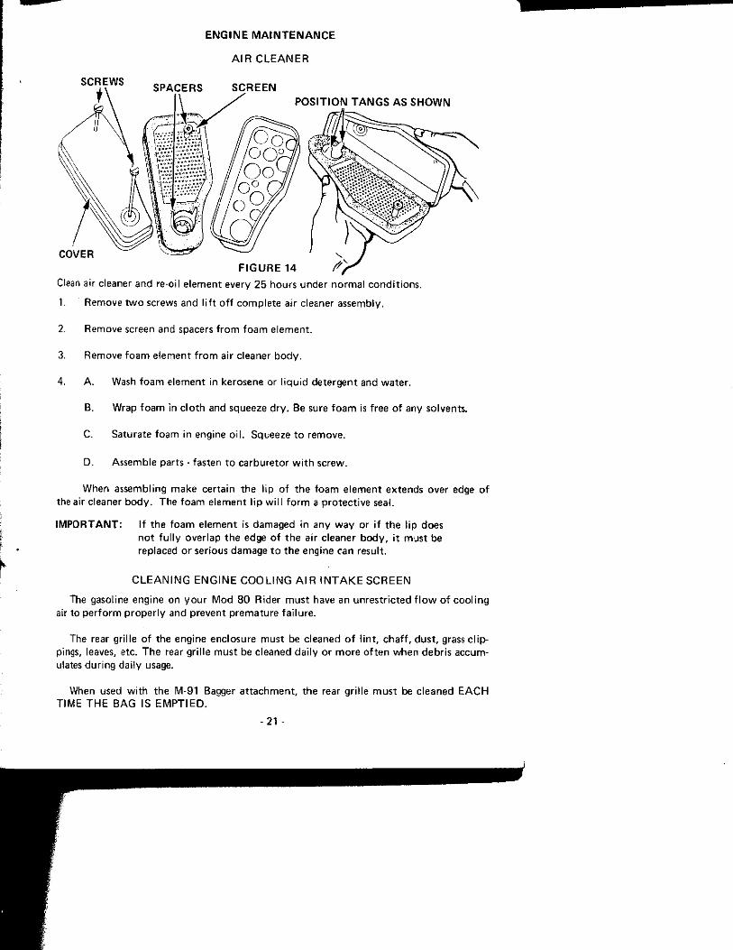
E N G I N E M A I N T E N A N C E
A I R C L E A N E R
S C R E W S S P A C E R S S C R E E N
C O V E R
P O S I T I O N T A N G S A S S H O W N
F I G U R E 14
Clean air cleaner and re-oil e l emen t every 2 5 hou rs under n o r m a l c o n d i t i o n s .
1. Remove t w o screws and l i f t o f f c o m p l e t e air cleaner assembly .
2. Remove screen and spacers f r o m f o a m e l e m e n t .
3. Remove f o a m e lemen t f r o m air c leaner b o d y .
4. A . Wash f o a m e lement in kerosene or l i q u i d de te rgen t and wa te r .
B. Wrap f o a m in c l o t h and squeeze d r y . Be sure f o a m is f ree o f any so lvents .
C. Saturate f o a m in engine o i l . Squeeze t o remove .
D. Assemble par ts - fasten t o ca rbu re to r w i t h screw.
When assembl ing m a k e cer ta in t he l ip o f t h e f o a m e l e m e n t ex tends over edge o f the air cleaner b o d y . The f o a m e lemen t Hp w i l l f o r m a p r o t e c t i v e seal.
I M P O R T A N T : I f t he f o a m e lemen t is damaged in any w a y or i f t he l ip does
The gasoline engine on y o u r M o d 8 0 Rider m u s t have an u n r e s t r i c t e d f l o w o f c o o l i n g air to p e r f o r m p r o p e r l y and p reven t p r e m a t u r e f a i l u re .
The rear gr i l le o f the eng ine enc losure m u s t be c leaned o f l i n t , c h a f f , d u s t , grass c l i p pings, leaves, etc. T h e rear gr i l le m u s t be c leaned da i l y o r m o r e o f t e n w h e n debr i s accumulates d u r i n g da i ly usage.
When used w i t h t he M-91 Bagger a t t a c h m e n t , t he rear gr i l le m u s t be c leaned E A C H T IME T H E B A G IS E M P T I E D .
n o t f u l l y over lap t h e edge o f t h e air c leaner b o d y , i t m u s t be replaced o r ser ious damage t o t h e engine can resul t .
C L E A N I N G E N G I N E C O O L I N G A I R I N T A K E S C R E E N
- 2 1 -

C A R B U R E T O R A D J U S T M E N T
I D L E S P E E D A D J U S T I N G S C R E W ' ^ j - ^ V A L V E
M A I N N E E D L E V A L V E
F I G U R E 15
M i n o r ca rbu re to r ad jus tmen ts may be requ i red t o compensate f o r d i f fe rences in fuel t e m p e r a t u r e , a l t i t ude and l oad .
The ca rbu re to r has th ree s imp le ad j us tmen t s :
1 . High Speed Fuel M i x t u r e A d j u s t m e n t (Ma in Needle Va lve)
2. Idle Fuel M i x t u r e A d j u s t m e n t , ( I d l e Valve)
3. Idle Speed A d j u s t m e n t .
1 , I n i t i a l A d j u s t m e n t :
A. T u r n m a i n needle valve c l o c k w i s e u n t i l i t j us t closes.
Valve m a y be damaged by t u r n i n g i t in t o o fa r .
B. T h e n o p e n m a i n needle valve 1-1/8 t u rns c o u n t e r c l o c k w i s e . Close id le valve ii same manner and open 1-1/8 tu rns , }
Th is in i t i a l a d j u s t m e n t w i l l p e r m i t t he engine t o be s ta r ted and w a r m e d up
p r i o r t o f ina l a d j u s t m e n t . :
-22 -
C A U T I O N : A v o i d c o n t a c t i n g h o t exhaus t p ipe w h e n y o u are adjus t ing ca rbu re to r .
Final A d j u s t m e n t :
A. T u r n m a i n needle valve in u n t i l engine misses { lean m i x t u r e ) . T h e n t u r n i t o u t past s m o o t h ope ra t i ng p o i n t u n t i l engine runs uneven ly ( r i ch m i x t u r e ) . N o w t u r n t o the m i d - p o i n t be tween r ich and lean so the engine runs s m o o t h l y .
B. Ho ld t h r o t t l e at id le p o s i t i o n and set idle speed ad jus t i ng screw u n t i l fas t idle is ob ta ined { 1 7 5 0 R P M ) .
C. H o l d t h r o t t l e i n idle p o s i t i o n and t u r n id le valve i n ( lean) and o u t ( r i ch ) u n t i l engine idles s m o o t h l y .
D. T h e n reset idle speed ad jus t i ng screw so t h a t eng ine idles at 1750 R P M .
Acce le ra t i on :
Engine shou ld accelerate w i t h o u t hes i ta t i on or s p u t t e r i n g . I f engine does n o t accelerate p r o p e r l y , the c a r b u r e t o r shou ld be re-adjusted t o a s l i gh t l y r icher m i x t u r e ( i .e. , open main needle valve s l i g h t l y ) .
R id ing Lawn Mower U n d e r L o a d :
Loss of power , t endency t o s ta l l , o r excessive b a c k f i r i n g all ind ica te a lean m i x t u r e . Open the " M a i n " needle valve in 1/8 t u r n g radua t i ons u n t i l engine runs s m o o t h l y . Ope ra t i ng the engine o n t o o lean a m i x t u r e causes loss o f p o w e r and h igh exhaus t heat. I f m i x t u r e is t o o r i c h , the engine w i l l sound as t h o u g h f l o o d e d and da rk smoke w i l l appear in t he exhaus t f umes .
N O T E : Er ra t i c engine o p e r a t i o n can also be caused b y d i r t o r o the r f o r e i g n mater ia l in t he ca rbu re to r . C a r b u r e t i o n o n smal l gasol ine engines is a lways c r i t i ca l o f d i r t . I t is r e c o m m e n d e d t ha t a f i l t e r i n g fue l f u n n e l a lways be used a long w i t h c lean gasol ine. A l s o check the f i l te r in the t a n k o u t l e t f i t t i n g p e r i o d i c a l l y .
C A U T I O N : Do n o t change the engine governor set t ings or over speed the engine.
E N G I N E L U B R I C A T I O N
See E N G I N E L U B R I C A T I O N o n page 12 o f th is m a n u a l .
- 2 3 -
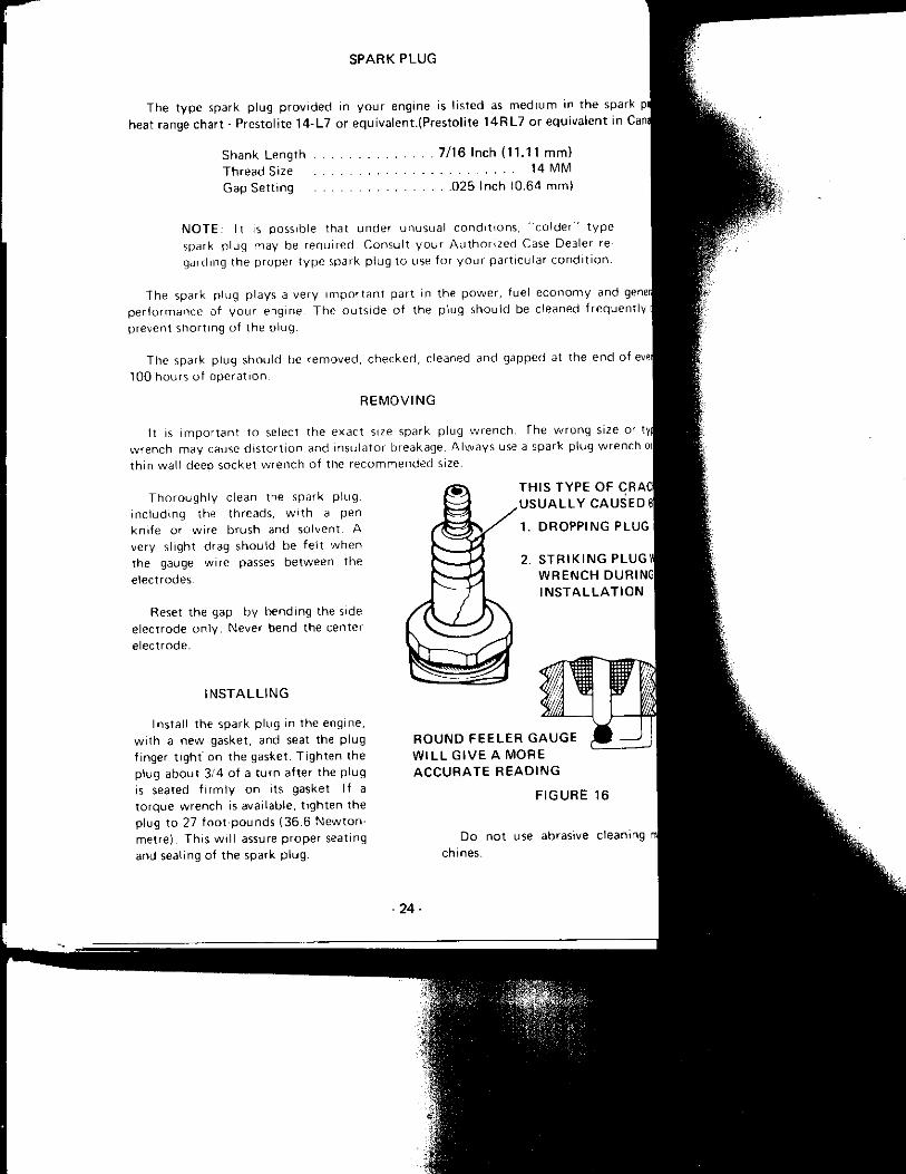
S P A R K P L U G
The t y p e spark p lug p r o v i d e d in y o u r engine is l i s ted as m e d i u m in t he spark plJ heat range char t - Pres to l i te 1 4 - L 7 or equ iva len t . (Pres to l i te 1 4 R L 7 o r equ i va len t in Cana[
Shank L e n g t h 7 /16 Inch ( 1 1 . 1 1 m m ) T h r e a d Size 14 M M Gap Se t t i ng 0 2 5 I n c h (0 .64 m m )
M O T E . It I S possible that under unusua l c o n d i t i o n s , " c o l d e r " t y p e spark p lug may be requ i red . Consu l t y o u r A u t h o r i z e d Case Dealer re gard ing the p roper t y p e spark p lug t o use f o r y o u r pa r t i cu la r c o n d i t i o n .
The spark p lug p lays a very i m p o r t a n t part in the p o w e r , fue l e c o n o m y and generj p e r l o r m a n c e of y o u r engine T h e o u t s i d e of t he p lug shou ld be c leaned f r equen t l y prevent sho r t i ng of the p lug
The spark p lug shou ld be r e m o v e d , c h e c k e d , c leaned and gapped at the end of evei| 100 hours of o p e r a t i o n .
R E M O V I N G
It IS i m p o r t a n t to select the exac t size spark p lug w r e n c h . T h e w r o n g size o-- tya w r e n c h may cause d i s t o r t i o n and insu la to r breakage. A l w a y s use a spark p lug w r e n c h t h i n wa l l deep socket w r e n c h of the r e c o m m e n d e d size.
T h o r o u g h l y c lean the spark p l ug , i n c l u d m g the threads, w i t h a pen k n i f e or w i re b rush and so lven t , A very s l ight drag shou ld be f e l t w h e n the gauge w i re passes be tween the e lec t rodes.
Reset t he gap by bend ing the side e lec t rode o n l y . Never bend the center e lec t rode .
I N S T A L L I N G
Insta l l the spark p lug in the eng ine, w i t h a new gasket, and seat the p lug f inger t i gh t ' on the gasket. T i g h t e n the p lug abou t 3 /4 o f a t u r n a f te r the p lug is seated f i r m l y o n its gasket I f a t o r q u e w r e n c h is avai lable, l i g h t e n the p lug t o 27 f o o t pounds ( 36 .6 N e w t o n -metre) . Th is w i l l assure p rope r seating and seal ing of the spark p l ug .
T H I S T Y P E O F CRACi U S U A L L Y C A U S E D el
1 . D R O P P I N G PLUG
S T R I K I N G P L U G ' W R E N C H DURINGI I N S T A L L A T I O N
R O U N D F E E L E R G A U G E W I L L G I V E A M O R E A C C U R A T E R E A D I N G
F I G U R E 16
D o n o t use abrasive c lean ing ch ines.
- 2 4 -

T O E - I N A D J U S T M E N T
1. Locate the r id ing m o w e r o n a ha rd level surface p re fe rab l y conc re te . Place f r o n t wheels in a s t ra ight ahead p o s i t i o n .
2. Make sure the f r o n t t i re pressures are equa l .
3. The f r o n t t i res shou ld s h o w a m o l d pa r t - l i ne w h i c h co inc ides w i t h the cen te r l i ne o f the t i re . If the cen te r l i ne o f the t i re is n o t read i l y v is ib le , t hen the whee l can be raised off the g r o u n d , spun and m a r k e d at t he a p p r o x i m a t e cen te r l i ne l o c a t i o n .
4. Measure the d is tance be tween the t i re center l ines or the cha lk marks .
M E A S U R E M E N T " A " M U S T BE 1/8 T O 3 / 8 - I N C H (3 m m T O 10 m m ) LESS T H A N M E A S U R E M E N T B. B O T H M E A -S U R E M E N T S - F R O N T A N D R E A R M U S T BE T A K E N A T S P I N D L E H E I G H T A B O V E T H E F L O O R .
F R O N T 1> R E A R
M E A S U R E M E N T " A '
M E A S U R E M E N T " B '
F I G U R E 17 AS V I E W E D F R O M T H E B O T T O M
5. Loosen b o t h j a m nu ts on each drag l i n k and t u r n rods e q u a l l y .
6. Tu rn the t ie r o d i n or o u t of t he bal l j o i n t s as requ i red . Re t i gh ten the j am nu ts w h e n cor rec t t oe in is o b t a i n e d . One bal l j o i n t has l e f t h a n d th reads and t h e o t h e r r i gh t h a n d so i t is unnecessary t o d i sconnec t i t f r o m the k i n g p i n lugs. T u r n i n g the j o i n t s o f f t he tie r o d increases the toe in . T u r n i n g the j o in t s o n the t ie r o d decreases the t o e i n .
- 2 5 -

B A T T E R Y A N D B A T T E R Y C H A R G E R
Y o u r Model 80 Riding Lawn Mower is equipped with a 12 volt , 12 amp hour lead aci storage battery, used for starting the engine on ly . The engine has magneto ignition whi does not drain the battery whi le operating.
In order to maintain the battery state of charge, the battery charger suppl ied wi your machine should be used as fo l lows:
1. During average usage charge battery for one 24 hour interval at least once every days.
2. If engine is stopped and started frequent ly , charge battery at least once every 2 wee for one 24 hour interval or more often if necessary.
3 . T o increase battery service life, avoid allowing it to discharge complete ly be charge intervals.
4. If a battery charger other than the one supplied with y o u r machine is used , do n charge battery at a rate to exceed 1.8 A M P S .
5. Battery charger is designed for inside use only .
1. Raise engine enclosure and prop open with rod .
Z Connect the special polorized plug f rom the battery charger to the matching plug-the battery.
3. Plug battery charger into l l O v o l t A . C . outlet.
4. Charge battery for a 24 hour interval.
5. T o disconnect charger, first unplug f rom 110 volt A . C . outlet, then disconnect speci; plug at battery.
F I G U R E 18 B A T T E R Y C H A R G E R F I G U R E 19
C O N N E C T I N G T H E B A T T E R Y C H A R G E R
• 2 6 -
W I N T E R S T O R A G E O F B A T T E R Y
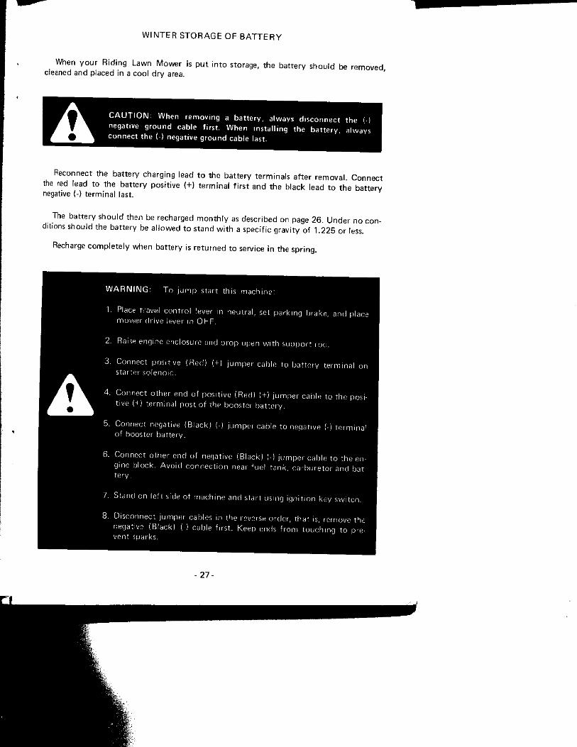
When y o u r R id i ng Lawn Mower is p u t i n t o storage, t he ba t te ry shou ld be r e m o v e d , cleaned and p laced in a coo l d r y area.
A C A U T I O N : When r e m o v i n g a b a t t e r y , a lways d i sconnec t the { t negative g r o u n d cable f i rs t . When ins ta l l i ng the b a t t e r y , a lways connec t the ( ) negat ive g r o u n d cable last.
Reconnect the ba t te ry charg ing lead t o t he ba t t e r y t e rm ina l s a f te r r e m o v a l . Connec t the red lead t o the ba t t e r y pos i t ive (+) t e rm ina l f i r s t and the b lack lead t o t h e ba t t e r y negative {-1 t e rm ina l l a s t
The ba t te ry shou ld then be recharged m o n t h l y as descr ibed on page 2 6 . U n d e r n o con ditions shou ld the ba t te ry be a l l o w e d t o s tand w i t h a spec i f ic g rav i t y of L 2 2 5 or less.
Recharge c o m p l e t e l y w h e n ba t t e r y is r e t u r n e d t o service i n the sp r ing .
W A R N I N G : T o j u m p star t th is m a c h i n e :
1. Place travel c o n t r o l lever in neu t ra l , set pa rk i ng brake, and place mower dr ive lever in O F F .
2. Raise engine enclosure and p r o p open w i t h s u p p o r t roc-
3. Connec t pos i t ive (Red) (+1 j u m p e r cable to ba t te ry te rm ina l on star te i so leno id .
4 . Connec t o ther end of i^osit ive (Red) ( + ) j u m p e r cable to t he posi-^ ^ K ^ ^ ^ t ive (H I t e rm ina l pos t o f the booster b a t t e r y .
5. Connec t negative (B lack ) (-) j u m p e i cable t o negat ive {•) t e r m i n a l of booster ba t t e r y .
6. Connec t o t he r end of negat ive (B l i i ck ) (•) j im ipe r cable t o t he engine b lock . A v o i d c o n n e c t i o n near fue l t ank , c a r b u r e t o r and batte ry .
7. Stand on le f t sirle of mach ine and star t using i g n i t i o n ksy s w i t c h ,
8. D isconnect jumpet cali les in the i everse o rder , tha t is, remove the negative (B lack) (-) cable f i i s t . Keep ends f r o m t o u c h i n g t o prevent sparks.
- 2 7 -

R U L E S F O R B A T T E R Y C A R E
C A U T I O N ; When work ing a round storage batteries, remember that all of the exposed metal parts are " l i ve" . Never lay a metal object
^ ^ k across the terminals as a spark or short c ircui t may result. Sparks, ^^k^^L l ighted matches and exposed f lames must be kept away f rom the ^Hr*̂ ^^ battery due to the presence of explosive gas in the battery. The
l iquid in the batteries is acid. Use care not to spill it on hands or clothing.
P O I S O N : Bat ter ies c o n t a i n su l f u r i c ac i d w h i c h can cause severe
A bu rns . A v o i d c o n t a c t w i t h sk in , eyes or c l o t h i n g . A n t i d o t e : E X T E R N A L , f l ush w i t h w a t e r ; I N T E R N A L , d r i n k large quant i t ies o f wa te r or m i l k . F o l l o w w i t h m i l k o f magnesia, beaten egg or vegetable o i l . Call phys i c i an i m m e d i a t e l y ; E Y E S , f l ush w i t h water f o r 15 m inu tes and get p r o m p t med ica l a t t e n t i o n . Keep o u t of reach o f c h i l d r e n .
D A N G E R ; Bat ter ies p roduce exp los ive charges. Keep sparks, flame
and c igaret tes away. V e n t i l a t e w h e n charg ing or using in enclosed
space. A l w a y s shield eyes w h e n w o r k i n g near ba t te r ies .
A C A U T I O N : Never wear r ings or meta l w a t c h bands w h e n work ing
w i t h the t r ac to r e lect r ica l sys tem or ba t te ry as y o u may g round a
l ive c i r cu i t -
1. A d d approved tap wa te r or d i s t i l l ed wa te r , as needed, t o keep t h e separators cover Check every 2 5 hours o r w e e k l y d e p e n d i n g o n a i r t e m p e r a t u r e . N o r m a l water t s u m p t i o n w o u l d be a p p r o x i m a t e l y 1 ounce ( 3 0 m l . ) every 25 h o u r s of ope ra t i on , is greater, e i t he r the case is leak ing or the ba t t e r y charger is ove rcha rg ing a n d must] rep laced.
2, Keep the b a t t e r y in a h e a l t h y s tate o f charge as s h o w n by h y d r o m e t e r readings. '
3, Make sure the ba t t e r y is securely fas tened in p o s i t i o n . Cable lead ing f r o m the batHJ shou ld no t lay o n the ba t t e r y con ta ine r .
4 . Keep the ba t te ry c lean and d r y .
IMPORTANT: T h e f u l l charge g rav i t y read ing is 1 .265 f o r a f u l l y charged battery] ba t t e r y hav ing a read ing o f 1 .175 w i l l f reeze at a p p r o x i m a t e l y 0 ° F( enhe i t ( -18°C} t e m p e r a t u r e .
I f a ba t t e r y w i l l n o t h o l d a charge, replace i t w i t h a n e w B a t t e r y m e e t i n g specificatii j as l i s ted in t he spec i f i ca t i on sec t i on .
- 2 8 -
A D D I N G W A T E R
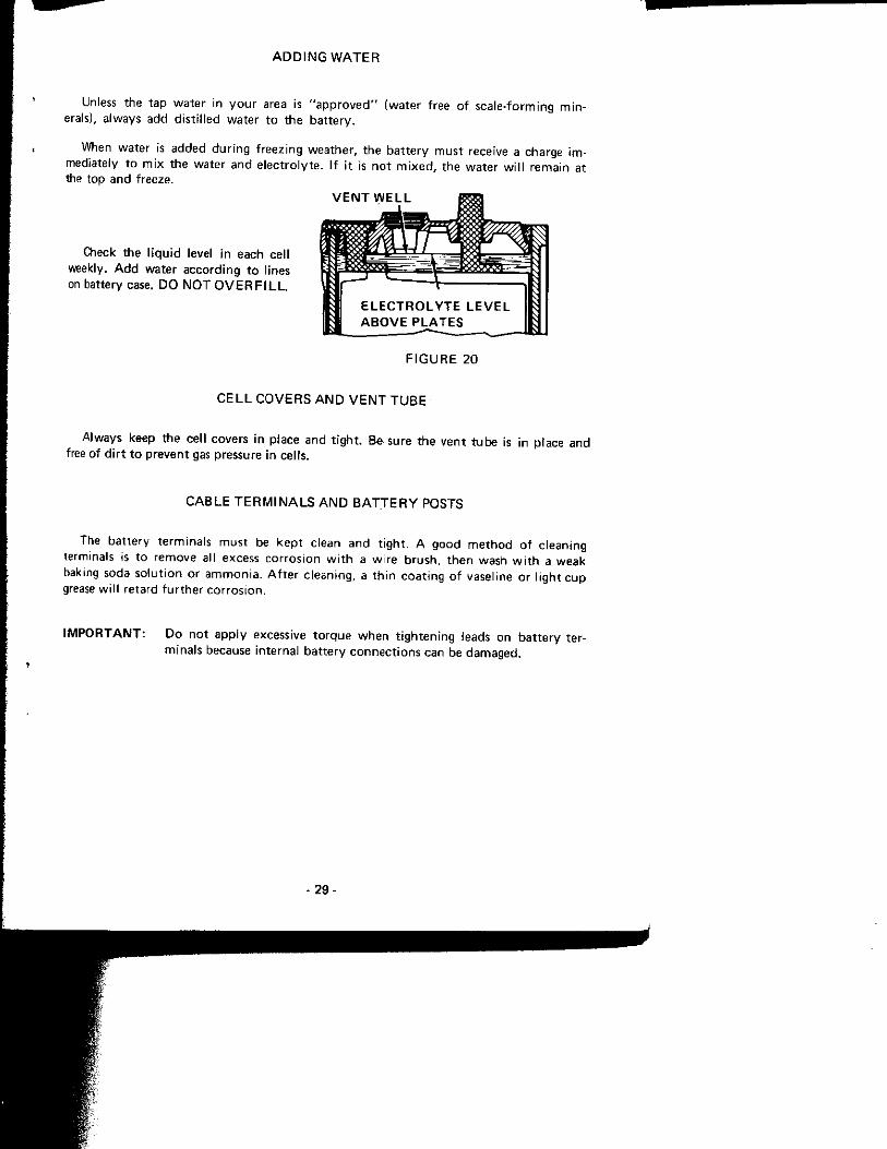
Unless the tap wa te r in y o u r area is " a p p r o v e d " (wa te r f ree o f sca le - fo rm ing m i n erals), a lways add d is t i l l ed wa te r t o t he b a t t e r y .
When water is added d u r i n g f reez ing wea ther , t he b a t t e r y m u s t receive a charge i m mediately t o m i x the water and e l e c t r o l y t e . I f i t is n o t m i x e d , the wa te r w i l l rema in at the top and freeze.
Check the l i q u i d level in each cel l weekly. A d d water acco rd i ng t o l ines on battery case. D O N O T O V E R F I L L .
F I G U R E 2 0
C E L L C O V E R S A N D V E N T T U B E
A lways keep the ce l l covers i n p lace and t i g h t . B e sure t h e v e n t t u b e is in place and free of d i r t t o p reven t gas pressure in cel ls.
C A B L E T E R M I N A L S A N D B A T J E R Y POSTS
The ba t te ry te rm ina ls mus t be k e p t c lean and t i gh t . A g o o d m e t h o d o f c lean ing terminals is t o remove all excess co r ros i on w i t h a w i r e b r u s h , t h e n wash w i t h a weak baktng soda s o l u t i o n or a m m o n i a . A f t e r c lean ing , a t h i n coa t i ng of vasel ine or l i gh t c u p grease w i l l re tard f u r t h e r c o r r o s i o n .
I M P O R T A N T : D o n o t a p p l y excessive t o r q u e w h e n t i g h t e n i n g leads on b a t t e r y term ina ls because in te rna l ba t t e r y c o n n e c t i o n s can be damaged .
- 29-
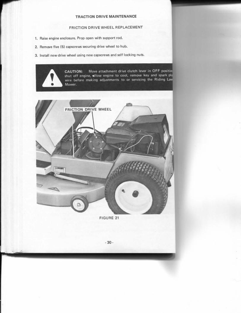
T R A C T I O N D R I V E M A I N T E N A N C E
F R I C T I O N D R I V E W H E E L R E P L A C E M E N T
1. Raise engine enclosure. Prop open with support rod.
2. Remove five (5) capscrews securing drive wheel to hub.
3. Install new drive wheel using new capscrews and self locking nuts.
A I
C A U T I O N : Move a t t a c h m e n t d r ive c l u t c h lever in O F F positior • shu t o f f eng ine, « l l o w engine t o c o o l , r emove key and spark plu; w i re be fo re m a k i n g ad jus tmen ts t o o r serv ic ing the R i d i n g Law M o w e r . ;
- 3 0 -

A D J U S T I N G T H E C L U T C H L I N K
Ease of sh i f t i ng and p roper d r ive wheel engagement are c o n t r o l l e d by t he c l u t c h l i nk .
Correct ad j us tmen t exists when t h e :
a. rubber dr ive wheel is in c o n t a c t w i t h disc w h e n c l u t c h - b r a k e pedal is released and
c lu tch l i n k is f ree ( t ha t is under ne i ther tens ion no r compress ion ) and
b. rubber wheel l i f t s clear o f disc w i t h c l u t c h - b r a k e pedal depressed h a l f w a y . (The second ha l f of pedal t ravel appl ies t he brake. )
To adjust :
a. loosen j a m n u t
b. remove bo l t secur ing ball j o i n t t o tab o n sp rocke t hous ing
c. tu rn ball j o i n t as requ i red
d. install b o l t and t i g h t e n jam n u t
- 3 1 -

D R I V E B E L T R E P L A C E M E N T
1. T h e m o w e r and m o w e r d r i ve be l t m u s t be r e m o v e d be fo re a t t e m p t i n g t o replace
t r a c t i o n dr ive be l t . Refer t o pages 3 4 and 3 5 .
2 . A f t e r the m o w e r d r ive be l t has been r e m o v e d . Push id ler a rm in t o r emove ten f r o m bel t .
3. S l i p o l d be l t o f f pu l leys and insta l l n e w be l t .
A C A U T I O N : Be sure gasol ine is t h o r o u g h l y d ra ined and battery m o v e d as descr ibed in the " S t o ' a g e " sec t ion of this m a n u a l bet' s tand ing mower uri end fo r storage or service.
• 3 2 -
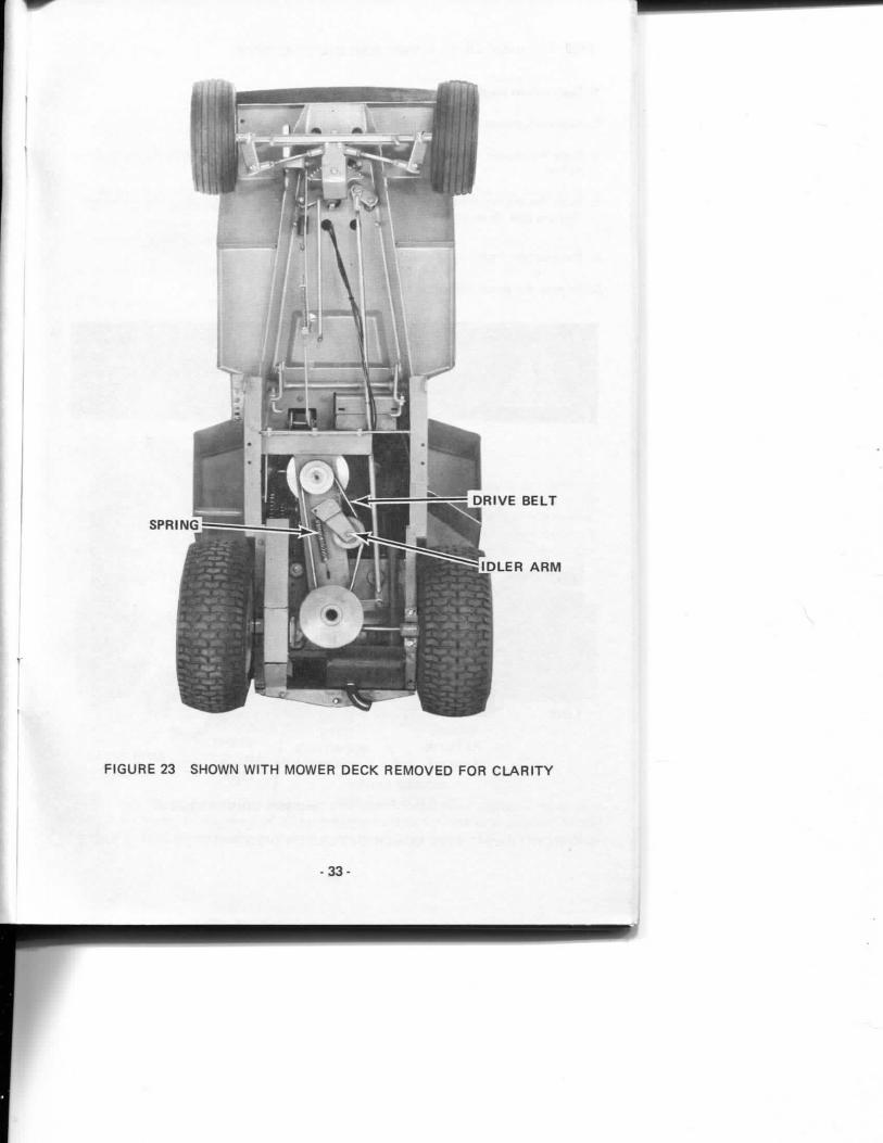
F I G U R E 23 S H O W N W I T H M O W E R D E C K R E M O V E D F O R C L A R I T Y
- 3 3 -

M O W E R D R I V E B E L T S E R V I C E
1. Place mower height selection in lowest posit ion.
2. Approach mower f rom left side.
3. Place the mower drive lever in the O F F posit ion. Sl ip belt off left side of mower drive pulley.
4. Place the mower drive lever in the O N posit ion (this lifts belt-brake away f rom belt). Remove belt f rom right side of mower drive pul ley.
5. Remove belt f rom engine pulley.
6. Reverse the above procedure for installation.
A C A U T I O N : Move at tachment drive c lutch lever in O F F position, shut off engine, a l low engine to coo l , remove key and spark plug wire before making adjustments to or servicing the Riding Lawn Mower.
F I G U R E 24 S H O W N W I T H L E F T S I D E M O W E R S U S P E N S I O N D I S C O N N E C T E D F O R C L A R I T Y
- 3 4 -
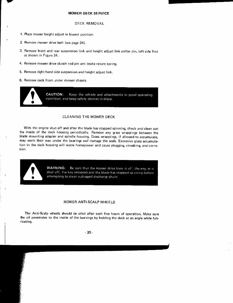
M O W E R D E C K S E R V I C E
D E C K R E M O V A L
1. Place mower he igh t ad jus t in l owes t p o s i t i o n .
2. Remove mower dr ive be l t (see page 3 4 ) .
3. Remove f r o n t and rear suspension l i n k and he igh t ad jus t l i n k c o t t e r p i n , l e f t side f i r s t as s h o w n in F igure 24 .
4 . Remove m o w e r dr ive c l u t c h r o d p i n and b rake r e t u r n sp r i ng .
5. Remove r igh t hand side suspension a n d he igh t ad jus t l i n k .
6. Remove deck f r o m under m o w e r chassis.
A C A U T I O N : Keep the yehlc le and a t t achmen ts in g o o d ope ra t i ng c o n d i t i o n , and keep safety devices in p lace.
C L E A N I N G T H E M O W E R D E C K
W i t h t h e engine shu t o f f and a f te r t he blade has s t o p p e d s p i n n i n g , check and clean o u t the inside o f the deck hous ing p e r i o d i c a l l y . Remove any grass wrapp ings be tween the blade m o u n t i n g adapter and sp ind le hous ing . Grass w rapp ings , i f a l l o w e d t o a c c u m u l a t e , may w o r k the i r way under the bearings and damage the seals. Excessive grass accumu la t i o n in t he deck hous ing w i l l waste h o r s e p o w e r and cause p lugg ing , s t reak ing , and c o r r o s ion .
A W A R N I N G : Be sure that t he m o w e r d r ive lever is o f f , t he engine is shu t o f f , the key removed and the b lade has s t o p p e d s p i n n i n g before a t t e m p t i n g t o c lean a p lugged discharge chu te .
M O W E R A N T I - S C A L P W H E E L S
The An t i -Sca lp wheels shou ld be o i l ed a f te r each f i ve hou rs o f o p e r a t i o n . Make sure the oi l penetrates t o the inside of t he bushings b y h o l d i n g the deck at an angle w h i l e l ub r ica t ing .
- 3 5 -

D E C K L E V E L I N G P R O C E D U R E
1. Side to Side Level
Position mower on level surface such as concrete garage f loor.
a. Set mower adjust lever in middle hole.
b. Place mower drive lever in the O F F posit ion.
c . Position blade at right angles to the Riding Lawn Mower chassis.
d. Turn Height-Adjust L ink adjusting nuts until blade tips are the same height from the floor (about 2 -1 /2 inches {65 m m ) .
2. Fore -Af t Level
Position mower on level surface such as concrete garage floor. Fo l low Side to Side Level adjustments, above, first.
a. Check to make sure that the mower drive lever is still in the O F F posit ion and that the mower adjust lever is in the middle hole.
b. Rotate the blade so it is parallel to the Riding L a w n Mower chassis.
c . T u r n the front suspension link adjustment nuts equally so the f ront tip of blade is:
a. 3 / 8 " to 1 / 2 " (10 m m to 12 m m ) lower than rear if M-91 bagger is instal led.
b. 1 /4" to 3 / 8 " (7 m m to 10 m m ) lower than rear if N O T equipped with M-91 bagger.
c. Th is adjustment should be made with operator's seat unoccupied and bagger (if so equipped) empty .
d. Recheck side to side level as described above and readjust if required.
F R O N T S U S P E N S I O N L I N K A D J U S T M E N T N U T S
H E I G H T A D J U S T L I N K A D J U S T M E N T N U T S
F I G U R E 2 5
- 3 6 -

B L A D E B O L T
F I G U R E 26
M O W E R B L A D E B O L T
Before operating the mower for the f irst t ime, c h e c k the bolt holding the blade. It must be tight. After the first 8 hours of operat ion, check it again. Whenever the blade is removed, it is good practice to install a new lockwasher under the bolt , and again check tightness after the next 8 hours of operat ion.
A C A U T I O N : Keep all nuts, bolts, and screws tight to be sure the equipment is in safe working condi t ion .
B E N T B L A D E
Check for bent blade before mounting the mower and after i m p a c t Blade tips should be within 1/4 inch (6 mm) of the same horizontal plane. Mowing with bent blade wil l cause missed strips and a poor mowing job. A bent blade should be replaced immediately.
A C A U T I O N : The vehicle and attachments should be stopped and inspected for damage after striking a foreign object, and the damage should be repaired before restarting and operating the equipment .
- 3 7 -

S H A R P E N I N G B L A D E
Wi th the engine shu t o f f and a f te r the b lade has s t o p p e d s p i n n i n g , check the mowe blade pe r i od i ca l l y f o r n i cks and dul lness. A damaged , du l l or i m p r o p e r l y sharpened bladf can cause a sha t te red , ra ther t h a n , c lean c u t and b r o w n areas or grass m a y deve lop . Refe t o F igure 27 f o r the c o r r e c t sha rpen ing angle.
A C A U T I O N : Move a t t a c h m e n t dr ive c l u t c h lever in O F F p o s i t i o n , shu t o f f eng ine, a l l o w eng ine t o c o o l , remove key and spark p lug w i re be fo re m a k i n g a d j u s t m e n t s t o or serv ic ing the R i d i n g Lawn M o w e r .
C O R R E C T A N G L E O F S H A R P E N E D C U T T I N G E D G E
W R O N G A N G L E T O S H A R P E N C U T T I N G E D G E
F I G U R E 27
B A L A N C I N G B L A D E
A f t e r a b lade is sharpened a lways check i t f o r ba lance. A ba lanc ing t o o l , such as shown b e l o w , can be o b t a i n e d f r o m y o u r local supp l ie r f o r t h i s pu rpose . A p r o p e r l y balanced blade w i l l level i tse l f w h e n p laced o n the ba lanc ing t o o l .
B L A D E C U T T I N G E D G E
F I G U R E 2 8
A C A U T I O N : A n unba lanced blade is hazardous and w i l l cause prem a t u r e wear and fa i l u re o f bearings and sp ind le . If the b lade c a n n o t be ba lanced by resharpen ing , replace i t w i t h a n e w o n e .
- 3 8 -
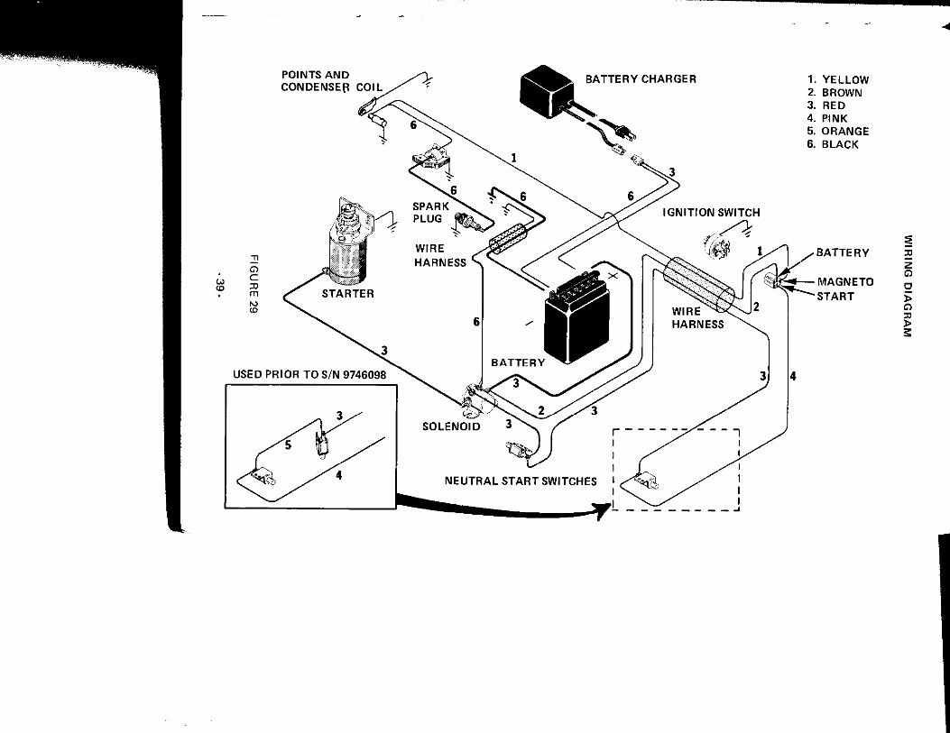
P O I N T S A N D C O N D E N S E R C O I L
B A T T E R Y C H A R G E R 1. Y E L L O W 2. B R O W N 3. R E D 4. P I N K 5. O R A N G E 6. B L A C K
B A T T E R Y 33
M A G N E T O
S T A R T a > a
>
S T O R I N G T H E R I D I N G L A W N M O W E R
If your Riding L a w n Mower will not be used for 3 0 days or more, the fol lowing storage procedures should be fo l lowed.
E N G I N E S T O R A G E
1. T o prevent gum deposits f rom forming in the fuel system, complete ly drain fuel tank and run engine until gasoline in carburetor is complete ly consumed .
2. While engine is still warm, drain oil f rom crank case and refill with fresh oil . See engine lubrication page for proper type and weight.
3. Remove spark plug, pour 2 or 3 tablespoons (30 ml) of S A E 30 oil into cy l inder and crank momentar i ly to distribute oi l . Replace spark plug.
4. Clean dirt and chaff f rom cyl inder head f ins and blower housing.
M O W E R D E C K
Clean grass accumulat ions f rom mower deck. See C L E A N I N G T H E M O W E R D E C K in M O W E R D E C K S E R V I C E sect ion of this manual .
B A T T E R Y S T O R A G E
When y o u r Riding Lawn Mower is put into storage the battery should be removed, cleaned and placed in a cool dry area.
£ \: W h e n r e m o v m g a b a t t e r y , a lways d i sconnec t the ( ) ^ A ^ ^ negat ive g r o u n d cable f i r s t W h e n ins ta lhng the b a t t e r y , a lways
^^^r^^^k connec t the (-) negative g r o u n d cable last.
Reconnect the battery charging lead to the battery terminals after removal . Connect the red lead to the battery positive (+) terminal and the black lead to the battery negative (-) terminal.
The battery should then be recharged monthly as described under B A T T E R Y MAINT E N A N C E . Under no condit ions should the battery be a l lowed to stand wi th a specific gravity of 1.225 or less.
Recharge completely when battery is returned to service in the spring.
L A W N M O W E R C H A S S I S
Thoroughly clean lawn mower chassis. Complete ly lubricate lawn mower as described in the Lubricat ion sect ion of this manual .
The Riding Lawn Mower may then be pushed to its storage area and stood on its end.
1. Be sure gasoline is thoroughly drained into an approved contamer to prevent leakage when mower is stood on end.
- 4 0 -

A C A U T I O N : Be sure gasol ine is t h o r o u g h l y d ra ined and ba t t e r y rem o v e d as descr ibed in t he " S t o r a g e " sec t ion o f th is m a n u a l be fo re s tand ing m o w e r o n end f o r storage or service.
2. Be sure t o R E M O V E B A T T E R Y be fo re l i f t i n g . T i p p i n g the b a t t e r y o n end w i l l cause m i n u t e par t ic les of sed imen t f r o m the b o t t o m o f t he ba t t e r y t o lodge be tween the cel l plates and consequen t l y r u i n t he b a t t e r y . W a r r a n t y w i l l n o t be a l l o w e d o n th is t y p e o f fa i lu re .
3. Care shou ld be used w h e n l i f t i n g t he u n i t t o avo id s t ra in and phys ica l i n j u r y . Be sure the u n i t is s tand ing securely be fo re w o r k i n g o n i t .
4 . Reach under a n d l i f t by t he f r o n t f r a m e area and N O T T H E F R O N T R U B B E R B U M PER.
5. A t t ach a c o r d or c h a i n be tween t h e uppe r p a r t o f t he L a w n M o w e r Chasis a n d t h e wa l l o r cei l ing. Th is w i l l p reven t t he u n i t f r o m fa l l i ng i f i t is acc iden ta l l y pushed or bumped .
I \ F I G U R E 3 0 S H O W N IN S T O R A G E P O S I T I O N
- 4 1 -

- N O T I C E -
A t the t i m e y o u r Case Dealer del ivers y o u r n e w r i d i n g m o w e r , h e w i l l a cqua in t you w i t h its o p e r a t i o n and ma in tenance as o u t l i n e d in t he " O w n e r War ran t y Reg i s t r a t i on " . When y o u r Dealer has c o m p l e t e d these i n s t r u c t i o n s , he w i l l ask y o u t o sign the r e p o r t and w i l l then h a n d y o u a c o p y f o r y o u r records.
A C A U T I O N : Use care when p u l l i n g loads or using heavy equ ip m e n t .
a. Use o n l y app roved d rawba r h i t c h p o i n t .
b. L i m i t loads t o those y o u can safely c o n t r o l .
c. Do n o t t u r n sha rp l y . Use care w h e n back ing .
d. Use c o u n t e r w e i g h t { s l or wheel we igh ts w h e n suggested in the own i ; r ' s m a n u a l .
•42 -

ATTACHMENTS
M O D E L M-92 T H A T C H E R
M O D E L L-90 S W E E P E R
- 4 3 -