This Page Intentionally Left Blank - scientific-sims.com · PDF fileCFD Vision 2030 Study: ......
55
Transcript of This Page Intentionally Left Blank - scientific-sims.com · PDF fileCFD Vision 2030 Study: ......


This Page Intentionally Left Blank

CFD Vision 2030 Study: A Path to Revolutionary Computational Aerosciences
NASA Vision 2030 CFD Code
Contract NNL08AA16B
Task NNL12AD05T
J. Slotnick and A. Khodadoust
Boeing Research & Technology
J. Alonso
Stanford University
D. Darmofal
Massachusetts Institute of Technology
W. Gropp
National Center for Supercomputing Applications
E. Lurie
Pratt & Whitney
D. Mavriplis
University of Wyoming
Prepared for NASA Langley Research Center
Hampton, Virginia 23681-2199
November 22, 2013

CFD Vision 2030 Study: A Path To Revolutionary Computational Aerosciences ii
Table of Contents
1 EXECUTIVE SUMMARY .............................................................................................................................. 1
2 INTRODUCTION ............................................................................................................................................ 4
3 VISION OF CFD IN 2030 ................................................................................................................................ 5
4 CURRENT STATE .......................................................................................................................................... 6
5 CFD TECHNOLOGY GAPS AND IMPEDIMENTS................................................................................... 9
5.1 Effective Utilization of High-Performance Computing (HPC) ..................................................................9
CASE STUDY 1: Current Utilization of HPC at NASA .........................................................................10
5.2 Unsteady Turbulent Flow Simulations Including Transition and Separation ...........................................12
CASE STUDY 2: LES Cost Estimates and 2030 Outlook ......................................................................13
5.3 Autonomous and Reliable CFD Simulation .............................................................................................15
CASE STUDY 3: Scalable Solver Development .....................................................................................16
5.4 Knowledge Extraction and Visualization .................................................................................................18
5.5 Multidisciplinary/Multiphysics Simulations and Frameworks .................................................................18
6 TECHNOLOGY DEVELOPMENT PLAN ................................................................................................. 20
6.1 Grand Challenge Problems .......................................................................................................................20
CASE STUDY 4: Impact of CFD Tool Development on NASA Science and Space Exploration
Missions ...................................................................................................................................................21
6.2 Technology Roadmap ...............................................................................................................................22
7 RECOMMENDATIONS ............................................................................................................................... 27
7.1 Development of a Comprehensive Revolutionary Computational Aerosciences Program ......................28
7.2 Programmatic Considerations ..................................................................................................................30
CASE STUDY 5: Community Verification and Validation Resources .................................................32
7.3 Strategic Considerations ...........................................................................................................................33
CASE STUDY 6: Sponsored Research Institutes ....................................................................................34
8 CONCLUSIONS ............................................................................................................................................. 37
9 ACKNOWLEDGMENTS .............................................................................................................................. 37
10 REFERENCES ............................................................................................................................................... 37
APPENDIX A. HIGH PERFORMANCE COMPUTING TRENDS AND FORECAST FOR 2030 ............. 45
List of Figures
Figure 1. Technology Development Roadmap ………………………………………………………………… .. 23
Figure 2. Proposed Enhanced Revolutionary Computational Sciences Program ....................................................29
Figure 3. Proposed New Revolutionary Computational Sciences (RCA) Program Structure .................................29
Figure 4. Changing Predictions About Semiconductor Sizes ..................................................................................45
List of Tables
Table 1. Estimated Performance for Leadership-class Systems ................................................................................49

CFD Vision 2030 Study: A Path To Revolutionary Computational Aerosciences 1
1 Executive Summary
The ability to simulate aerodynamic flows using computa-
tional fluid dynamics (CFD) has progressed rapidly during
the last several decades and has fundamentally changed the
aerospace design process. Advanced simulation capabilities
not only enable reductions in ground-based and in-flight
testing requirements, but also provide added physical in-
sight, enable superior designs at reduced cost and risk, and
open new frontiers in aerospace vehicle design and perfor-
mance. Throughout the evolution of physics-based simula-
tion technologies in general, and computational fluid dy-
namics methods in particular, NASA’s Aeronautics Re-
search Mission Directorate has played a leading role in the
development and deployment of these technologies. How-
ever, today the aerospace CFD community finds itself at a
crossroads due to the convergence of several factors. In
spite of considerable successes, reliable use of CFD has
remained confined to a small but important region of the
operating design space due to the inability of current meth-
ods to reliably predict turbulent-separated flows. At the
same time, High Performance Computing (HPC) hardware
is progressing rapidly and is on the cusp of a paradigm shift
in technology that may require a rethinking of current CFD
algorithms and software. Finally, during the last decade,
government investment in simulation-based technology for
aerospace applications has been significantly reduced and
access to leading-edge HPC hardware has been constrained
both in government and industry. Sustaining future advanc-
es in CFD and related multidisciplinary analysis and opti-
mization tools will be critical for achieving NASA’s aero-
nautics goals, invigorating NASA’s space program, keeping
industry competitive, and advancing aerospace engineering
in general. The improvement of a simulation-based engi-
neering design process in which CFD plays a critical role is
a multifaceted problem that requires a comprehensive long-
term, goal-oriented research strategy. The objective of this
report is to develop such a plan, based on factual infor-
mation, expert knowledge, community input, and in-depth
experience.
This report represents the findings and recommendations of a
multidisciplinary team that was assembled in response to a
NASA Research Announcement (NRA) with the goal of
formulating a knowledge-based forecast and research strate-
gy for developing a visionary CFD capability in the notional
year 2030. The diverse team members bring together deep
expertise in the areas of aerodynamics, aerospace engineer-
ing, applied mathematics, and computer science, and the
team includes members with extensive experience from in-
dustry, academia, and government. A multipronged strategy
was adopted for gathering information and formulating a
comprehensive research plan. Input from the broader interna-
tional technical community was sought, and this was ob-
tained initially through the development and compilation of
an online survey that garnered more than 150 responses. As a
follow-up, a workshop was held with academic, industrial,
and government participants from the general aerospace en-
gineering community with a stake in simulation-based engi-
neering. The results from the survey and workshop were syn-
thesized and refined by the team, with considerable additions
through internal discussions and feedback from sponsoring
NASA officials. The overall project spanned a period of 12
months and resulted in a series of findings, a vision for the
capabilities required in the year 2030, and a set of recom-
mendations for achieving these capabilities.
Findings
1. NASA investment in basic research and technology
development for simulation-based analysis and de-
sign has declined significantly in the last decade and
must be reinvigorated if substantial advances in
simulation capability are to be achieved. Advancing
simulation capabilities will be important for both na-
tional aeronautics and space goals, and has broad im-
plications for national competitiveness. This will re-
quire advances in foundational technologies, as well as
increased investment in software development, since
problem and software complexity continue to increase
exponentially.
2. HPC hardware is progressing rapidly and technolo-
gies that will prevail are difficult to predict. However,
there is a general consensus that HPC hardware is on the
cusp of a paradigm shift that will require significantly
new algorithms and software in order to exploit emerg-
ing hardware capabilities. While the dominant trend is
toward increased parallelism and heterogeneous archi-
tectures, alternative new technologies offer the potential
for radical advances in computational capabilities, alt-
hough these are still in their infancy.
3. The use of CFD in the aerospace design process is
severely limited by the inability to accurately and re-
liably predict turbulent flows with significant regions
of separation. Advances in Reynolds-averaged Navier-
Stokes (RANS) modeling alone are unlikely to over-
come this deficiency, while the use of Large-eddy simu-
lation (LES) methods will remain impractical for various
important applications for the foreseeable future, barring
any radical advances in algorithmic technology. Hybrid
RANS-LES and wall-modeled LES offer the best pro-
spects for overcoming this obstacle although significant
modeling issues remain to be addressed here as well.
Furthermore, other physical models such as transition
and combustion will remain as pacing items.
4. Mesh generation and adaptivity continue to be signif-
icant bottlenecks in the CFD workflow, and very lit-
tle government investment has been targeted in these
areas. As more capable HPC hardware enables higher
resolution simulations, fast, reliable mesh generation and
adaptivity will become more problematic. Additionally,
adaptive mesh techniques offer great potential, but have

CFD Vision 2030 Study: A Path To Revolutionary Computational Aerosciences 2
not seen widespread use due to issues related to software
complexity, inadequate error estimation capabilities, and
complex geometries.
5. Revolutionary algorithmic improvements will be re-
quired to enable future advances in simulation capa-
bility. Traditionally, developments in improved discreti-
zations, solvers, and other techniques have been as im-
portant as advances in computer hardware in the devel-
opment of more capable CFD simulation tools. Howev-
er, a lack of investment in these areas and the supporting
disciplines of applied mathematics and computer science
have resulted in stagnant simulation capabilities. Future
algorithmic developments will be essential for enabling
much higher resolution simulations through improved
accuracy and efficiency, for exploiting rapidly evolving
HPC hardware, and for enabling necessary future error
estimation, sensitivity analysis, and uncertainty quantifi-
cation techniques.
6. Managing the vast amounts of data generated by
current and future large-scale simulations will con-
tinue to be problematic and will become increasingly
complex due to changing HPC hardware. These in-
clude effective, intuitive, and interactive visualization of
high-resolution simulations, real-time analysis, man-
agement of large databases generated by simulation en-
sembles, and merging of variable fidelity simulation data
from various sources, including experimental data.
7. In order to enable increasingly multidisciplinary
simulations, for both analysis and design optimiza-
tion purposes, advances in individual component
CFD solver robustness and automation will be re-
quired. The development of improved coupling at high
fidelity for a variety of interacting disciplines will also
be needed, as well as techniques for computing and cou-
pling sensitivity information and propagating uncertain-
ties. Standardization of disciplinary interfaces and the
development of coupling frameworks will increase in
importance with added simulation complexity.
Vision
A knowledge-based vision of the required capabilities of
state-of-the-art CFD in the notional year 2030 is developed
in this report. The Vision 2030 CFD capability is one that:
Is centered on physics-based predictive modeling.
Includes automated management of errors and uncer-
tainties.
Provides a much higher degree of automation in all steps
of the analysis process.
Is able to effectively leverage the most capable HPC
hardware of the day.
Has the flexibility to tackle large-scale capability tasks
in a research environment but can also manage large
numbers of production jobs for database applications.
Seamlessly integrates with other disciplinary codes for
enabling complex multidisciplinary analyses and opti-
mizations.
The Vision includes a much higher level of integration be-
tween advanced computational methods and improved
ground-based and flight test techniques and facilities in order
to best advance aerospace product development efforts and
reduce technical risk in the future.
A number of Grand Challenge (GC) problems are used that
constitute the embodiment of this vision of the required CFD
capabilities in 2030, and cover all important application areas
of relevance to NASA’s aeronautics mission as well as im-
portant aspects of NASA’s space exploration mission. Four
GC problems have been identified:
1. Wall resolved LES simulation of a full powered air-
craft configuration in the full flight envelope
2. Off-design turbofan engine transient simulation
3. Multidisciplinary Analysis and Optimization (MDAO)
of a highly flexible advanced aircraft configuration
4. Probabilistic analysis of a powered space access con-
figuration
These Grand Challenge problems are chosen because they
are bold and will require significant advances in HPC us-
age, physical modeling, algorithmic developments, mesh
generation and adaptivity, data management, and multidis-
ciplinary analysis and optimization to become feasible. In
fact, they may not be achievable in the 2030 time frame, but
are used as drivers to identify critical technologies in need
of investment and to provide benchmarks for continually
measuring progress toward the long-term goals of the re-
search program.
Recommendations
In order to achieve the Vision 2030 CFD capabilities, a
comprehensive research strategy is developed. This is for-
mulated as a set of recommendations which, when consid-
ered together, result in a strategy that targets critical disci-
plines for investment, while monitoring progress toward the
vision. Two types of recommendations are made: a set of
specific programmatic recommendations and a series of
more general strategic recommendations. The programmat-
ic recommendations avoid the identification of specific
technologies and the prescription of funding levels, since
these decisions are difficult at best given the long-range
nature of this planning exercise. Rather, long-range objec-
tives are identified through the vision and GC problems,
and a set of six general technology areas that require sus-
tained investment is described. A mechanism for prioritiz-
ing current and future investments is suggested, based on
the periodic evaluation of progress toward the GC prob-
lems.

CFD Vision 2030 Study: A Path To Revolutionary Computational Aerosciences 3
Programmatic Recommendation 1: NASA should devel-
op, fund, and sustain a base research and technology
(R&T) development program for simulation-based analy-
sis and design technologies. The presence of a focused base
R&T program for simulation technologies is an essential
component of the strategy for advancing CFD simulation
capabilities. This recommendation consists of expanding the
current Revolutionary Computational Aerosciences (RCA)
program and organizing it around six technology areas identi-
fied in the findings:
1. High Performance Computing (HPC)
2. Physical Modeling
3. Numerical Algorithms
4. Geometry and Grid Generation
5. Knowledge Extraction
6. MDAO
The physical modeling area represents an expansion of the
current turbulence modeling area under the RCA program
to encompass other areas such as transition and combustion,
while the numerical algorithms area corresponds to a cur-
rent emphasis in the RCA program that must be broadened
substantially. The other areas constitute new, recommended
thrust areas within the RCA program.
Programmatic Recommendation 2: NASA should devel-
op and maintain an integrated simulation and software
development infrastructure to enable rapid CFD technol-
ogy maturation. A leading-edge in-house simulation capa-
bility is imperative to support the necessary advances in CFD
required for meeting the 2030 vision. Maintaining such a
capability will be crucial for understanding the principal
technical issues and overcoming the impediments, for inves-
tigating new techniques in a realistic setting, and for engag-
ing with other stakeholders. In order to be sustainable, dedi-
cated resources must be allocated toward the formation of a
streamlined and improved software development process that
can be leveraged across various projects, lowering software
development costs, and releasing researchers and developers
to focus on scientific or algorithmic implementation aspects.
At the same time, software standards and interfaces must be
emphasized and supported whenever possible, and open
source models for noncritical technology components should
be adopted.
Programmatic Recommendation 3: NASA should utilize
and optimize HPC systems for large-scale CFD develop-
ment and testing. Access to large-scale HPC hardware is
critical for devising and testing the improvements and novel
algorithms that will be required for radically advancing CFD
simulation capabilities. Although the current NASA para-
digm favors computing for many small, production jobs
(“capacity”) over larger, proof-of-concept jobs (“capability”),
a mechanism must be found to make large-scale HPC hard-
ware available on a regular basis for CFD and multidiscipli-
nary simulation software development at petascale to ex-
ascale levels and beyond. This may be done through internal
reallocation of resources, sharing with other NASA mission
directorates, leveraging other government agency HPC as-
sets, or through any combination of these approaches.
Programmatic Recommendation 4: NASA should lead
efforts to develop and execute integrated experimental
testing and computational validation campaigns. System-
atic numerical validation test datasets and effective mecha-
nisms to disseminate validation results are becoming more
important as CFD complexity increases. NASA is ideally
positioned to lead such efforts by leveraging its unique exper-
imental facilities in combination with its extensive in-house
CFD expertise, thus contributing valuable community re-
sources that will be critical for advancing CFD technology.
The development of new experimental testing technologies
and facilities is expected to play a continuing role not just in
aerospace product development, but increasingly in computa-
tional method validation.
Strategic Recommendation 5: NASA should develop, fos-
ter, and leverage improved collaborations with key re-
search partners and industrial stakeholders across disci-
plines within the broader scientific and engineering
communities. In an environment of limited resources,
achieving sustained critical mass in the necessary simulation
technology areas will require increased collaborations with
other stakeholders. Mutually beneficial collaborations are
possible between NASA mission directorates, as well as with
other US government agencies with significant ongoing in-
vestments in computational science. Tighter collaboration
with industry, specifically in simulation technology areas,
would also be beneficial to both parties and a joint Computa-
tional Science Leadership team is proposed to coordinate
such collaborations. At the same time, investments must look
beyond the traditional aerospace engineering disciplines to
drive substantial advances in simulation technology, and
mechanisms for engaging the wider scientific community,
such as focused research institutes that engage the broader
academic community, should be explored.
Strategic Recommendation 6: NASA should attract
world-class engineers and scientists. The ability to achieve
the long-term goals for CFD in 2030 is greatly dependent on
having a team of highly educated and effective engineers and
scientists devoted to the advancement of computational sci-
ences. Mechanisms for engaging graduate and undergraduate
students in computational science with particular exposure to
NASA aeronautics problems must be devised. These include
student fellowships, as well as visiting programs and intern-
ships, which may be facilitated through external institutes
and centers.

CFD Vision 2030 Study: A Path To Revolutionary Computational Aerosciences 4
2 Introduction
The rapid advance of computational fluid dynamics (CFD)
technology during the last several decades has fundamentally
changed the aerospace design process. Aggressive use of
CFD is credited with drastic reductions in wind tunnel time
for aircraft development programs1-4
, as well as lower num-
bers of experimental rig tests in gas turbine engine develop-
ment programs.5-6
CFD has also enabled the design of high-
speed, access-to-space, and re-entry vehicles in the absence
of suitable ground-based testing facilities.7-9
In addition to
reducing testing requirements, physics-based simulation
technologies such as CFD offer the added potential of deliv-
ering superior understanding and insight into the critical
physical phenomena limiting component performance, thus
opening new frontiers in aerospace vehicle design.10-11
Physics-based simulations in general, and CFD in particular,
are front and center in any aerospace research program since
these are crosscutting technologies that impact all speed re-
gimes and all vehicle classes. This is evidenced in the Na-
tional Research Council (NRC) commissioned decadal sur-
vey on aeronautics12
which identifies five common themes
across the entire aeronautics research enterprise, the first two
being physics-based simulation and physics-based design
tools. Similarly, these technologies affect all of the outcomes
in the current National Aeronautics R&D Plan,13
and contin-
ued advances in these technologies will be critical for meet-
ing the stated outcomes.
Since the advent of scientific computing, NASA’s Aero-
nautics Research Mission Directorate (ARMD) has played a
leading role in the development and deployment of CFD
technologies.14
Successive external reviews of NASA Aero-
nautics programs during the last two decades by organiza-
tions such as the National Academy of Engineering (NAE)
and others12
have repeatedly praised the world-class status
and leading-edge technical contributions of the simulation-
based engineering tools developed under these programs. In
fact, many algorithms, techniques, and software tools in use
today within and beyond the aerospace industry can trace
their roots back to NASA development or funding.
The development of computational aerodynamics has been
characterized by a continual drive to higher fidelity and more
accurate methods from the 1970s to the 1990s, beginning
with panel methods, proceeding to linearized and nonlinear
potential flow methods, inviscid flow (Euler) methods, and
culminating with Reynolds-averaged Navier-Stokes (RANS)
methods. These advances were arrived at through sustained
investment in methodology development coupled with acqui-
sition and deployment of leading edge High Performance
Computing (HPC) hardware made available to researchers.15
While Moore’s law has held up remarkably well, delivering a
million-fold increase in computational power during the last
20 years, there is also ample evidence that equivalent or
greater increases in simulation capabilities were achieved
through the development of advanced algorithms within the
same time frame.1,16-18
However, the last decade has seen stagnation in the capabili-
ties used in aerodynamic simulation within the aerospace
industry, with RANS methods having become the high-
fidelity method of choice and advances due mostly to the use
of larger meshes, more complex geometries, and more nu-
merous runs afforded by continually decreasing hardware
costs.19-23
At the same time, the well-known limitations of
RANS methods for separated flows have confined reliable
use of CFD to a small region of the flight envelope or operat-
ing design space.24
Simultaneously, algorithmic development
has been substantially scaled back within NASA and access
to leading-edge HPC hardware has been constrained, both at
NASA and within industry.25
In some sense, current CFD has
become a commodity based on mature technology, suitable
only for commodity hardware and reliable only for problems
for which an extensive experience base exists.
Continued advances in physics-based simulation technolo-
gies in general, and CFD in particular, are essential if NASA
is to meet its aeronautics research goals, as well as for suc-
cessfully advancing the outcomes in the National Aero-
nautics R&D plan.13
The required advances in fuel burn,
noise, emissions, and climate impact will only be realized
with vastly more sophisticated analysis of future configura-
tions. Beyond Aeronautics, NASA’s space missions rely
heavily on computational tools developed within ARMD7-9,
26-30 and superior designs at lower cost and risk will require
radical advances in new CFD tools.31
Additionally, the loss
of the leadership role NASA ARMD once played in the de-
velopment of simulation-based engineering technology has
larger implications for the aerospace industry in particular,
and national competitiveness in general.17,32,33
Due to the
long lead times and high risk involved, industry must rely on
government agencies to develop and demonstrate new simu-
lation technologies at large scale, after some investment in
proof-of-concept at universities. In recent years, the National
Science Foundation (NSF) and Department of Energy (DOE)
have led investing in computational science-based research
and in deploying leading-edge HPC facilities, although with
a different focus based more on scientific discovery rather
than engineering product design.16, 18, 34-36
As noted by a blue-
ribbon panel report convened by the NSF, simulation-based
engineering is fundamentally different from science-based
simulation and is in danger of being neglected under the cur-
rent scenario, with important implications for national com-
petitiveness.37, 38
Thus, there is a national imperative to reinvigorate the in-
vestment in physics-based engineering simulation tools in
general, and in CFD in particular, and NASA is uniquely
positioned to fill this role. In addition to enhancement of
CFD technology, effective use of existing, and potentially
new, ground-based testing facilities will be required to pro-
vide a complementary set of tools to best advance aerospace

CFD Vision 2030 Study: A Path To Revolutionary Computational Aerosciences 5
product development efforts and reduce technical risk in the
future. Sustaining future advances in CFD and related multi-
disciplinary analysis and optimization tools along with strong
support of ground-based and flight testing technologies and
facilities will be key for achieving NASA next generation
aeronautics goals, keeping industry competitive, invigorating
NASA’s space program, and advancing aerospace engineer-
ing. With investment, the resulting engineering design pro-
cess would decrease risk, reduce time-to-market, improve
products, and facilitate truly revolutionary aerospace vehicles
through the ability to consider novel designs. Without such
an investment, the engineering design process will look much
the same in 2030 as it does today and act as a barrier to revo-
lutionary advances in aerospace and other industries of na-
tional importance.
The improvement of a simulation-based engineering design
process in which CFD plays a critical role is a multifaceted
problem. Having relied on mature algorithms and ridden the
wave of ever-decreasing commodity computer hardware
costs, the CFD development community now finds itself
poorly positioned to capitalize on the rapidly changing HPC
architectures, which include massive parallelism and hetero-
geneous architectures.38-40
New paradigms will be required to
harness the rapidly advancing capabilities of new HPC hard-
ware.41, 42
At the same time, the scale and diversity of issues
in aerospace engineering are such that increases in computa-
tional power alone will not be enough to reach the required
goals, and new algorithms, solvers, physical models, and
techniques with better mathematical and numerical properties
must be developed.1,16-18
Finally, software complexity is in-
creasing exponentially, slowing adoption of novel techniques
into production codes and shutting out production of new
software development efforts, while simultaneously compli-
cating the coupling of various disciplinary codes for multi-
disciplinary analysis and design.43
The development of a
long-range research plan for advancing CFD capabilities
must necessarily include all these considerations, along with
the larger goal of comprehensive advances in multidiscipli-
nary analysis and optimization capabilities.
The objective of this study is to develop such a plan, based
on factual information, expert knowledge, and the in-depth
experience of the team and the broader community. The
strategy begins by defining the required capabilities for CFD
in the notional year 2030. By contrasting this vision with the
current state, we identify technical impediments and formu-
late a technology development plan. This in turn is used to
develop a research strategy for achieving the goals of the
Vision 2030 CFD capability. The outcome of the research
plan is a set of recommendations formulated to enable the
successful execution of the proposed strategy.
3 Vision of CFD in 2030
Given the inherent difficulties of long-term predictions, our
vision for CFD in 2030 is grounded on a desired set of capa-
bilities that must be present for a radical improvement in
CFD predictions of critical flow phenomena associated with
the key aerospace product/application categories, including
commercial and military aircraft, engine propulsion, ro-
torcraft, space exploration systems, launch vehicle programs,
air-breathing space-access configurations, and spacecraft
entry, descent, and landing (EDL).
This set of capabilities includes not only the accurate and
efficient prediction of fluid flows of interest, but also the
usability of CFD in broader contexts (including uncertainty
quantification, optimization, and multidisciplinary applica-
tions) and in streamlined/automated industrial analysis and
design processes. To complicate things further, CFD in 2030
must effectively leverage the uncertain and evolving envi-
ronment of HPC platforms that, together with algorithmic
improvements, will be responsible for a large portion of the
realized improvements.
The basic set of capabilities for Vision 2030 CFD must in-
clude, at a minimum:
1. Emphasis on physics-based, predictive modeling. In
particular, transition, turbulence, separation, chemically
reacting flows, radiation, heat transfer, and constitutive
models must reflect the underlying physics more closely
than ever before.
2. Management of errors and uncertainties resulting from
all possible sources: (a) physical modeling errors and
uncertainties addressed in item #1, (b) numerical errors
arising from mesh and discretization inadequacies, and
(c) aleatory uncertainties derived from natural variabil-
ity, as well as epistemic uncertainties due to lack of
knowledge in the parameters of a particular fluid flow
problem.
3. A much higher degree of automation in all steps of the
analysis process is needed including geometry creation,
mesh generation and adaptation, the creation of large da-
tabases of simulation results, the extraction and under-
standing of the vast amounts of information generated,
and the ability to computationally steer the process. In-
herent to all these improvements is the requirement that
every step of the solution chain executes high levels of
reliability/robustness to minimize user intervention.

CFD Vision 2030 Study: A Path To Revolutionary Computational Aerosciences 6
4. Ability to effectively utilize massively parallel, hetero-
geneous, and fault-tolerant HPC architectures that will
be available in the 2030 time frame. For complex physi-
cal models with nonlocal interactions, the challenges of
mapping the underlying algorithms onto computers with
multiple memory hierarchies, latencies, and bandwidths
must be overcome.
5. Flexibility to tackle capability- and capacity-computing
tasks in both industrial and research environments so
that both very large ensembles of reasonably-sized solu-
tions (such as those required to populate full-flight enve-
lopes, operating maps, or for parameter studies and de-
sign optimization) and small numbers of very-large-
scale solutions (such as those needed for experiments of
discovery and understanding of flow physics) can be
readily accomplished.
6. Seamless integration with multidisciplinary analyses that
will be the norm in 2030 without sacrificing accuracy or
numerical stability of the resulting coupled simulation,
and without requiring a large amount of effort such that
only a handful of coupled simulations are possible.
Included in this desired set of capabilities is a vision for how
CFD in 2030 will be used: a vision of the interaction between
the engineer/scientist, the CFD software itself, its framework
and all the ancillary software dependencies (databases, mod-
ules, visualization, etc.), and the associated HPC environ-
ment. A single engineer/scientist must be able to conceive,
create, analyze, and interpret a large ensemble of related sim-
ulations in a time-critical period (e.g., 24 hours), without
individually managing each simulation, to a pre-specified
level of accuracy. There should be less emphasis on the me-
chanics of running and collecting the information, and more
emphasis on interpreting and understanding the results of the
work. Like the predictive nature of large-scale, finite-
element-based, linear structural analyses that are assumed in
the aerospace industry, information derived from computa-
tions of fluid flow must carry the same stamp of approval or,
at least, a reasonable estimate of possible errors contained in
the information provided. At the moment, CFD is not yet
sufficiently predictive and automated to be used in criti-
cal/relevant engineering decisions by the non-expert user,
particularly in situations where separated flows are present.
Additionally, the Vision includes a much higher level of in-
tegration between advanced computational methods and im-
proved ground-based and flight test techniques and facilities
in order to best advance aerospace product development ef-
forts and reduce technical risk in the future.
Finally, as part of our vision, we define a set of Grand Chal-
lenge (GC) problems (as shown in the graphic on the next
page) that are bold and in fact may not be solvable in the
2030 timeframe, but are used as drivers to identify critical
technologies in need of investment, and to serve as bench-
marks for continually measuring progress toward the long-
term development goals. These GC problems were chosen
to embody the requirements for CFD in 2030, and cover all
important application areas of relevance to NASA’s aero-
nautics mission, as well as important aspects of NASA’s
space exploration mission. Details on the GC problems are
presented in Section 6.
4 Current State
At present, CFD is used extensively in the aerospace industry
for the design and analysis of air and space vehicles and
components. However, the penetration of CFD into aero-
space design processes is not uniform across vehicle types,
flight conditions, or across components. CFD often plays a
complementary role to wind tunnel and rig tests, engine certi-
fication tests, and flight tests by reducing the number of test
entries and/or reducing testing hours.3-5
But, in many circum-
stances, CFD provides the only affordable or available source
of engineering data to use in product design due to limita-
tions either with model complexity and/or wind tunnel capa-
bility, or due to design requirements that cannot be addressed
with ground-based testing of any kind.8, 10, 31
As a result, CFD
technology development has been critical in not only mini-
mizing product design costs, but also in enabling the design
of truly novel platforms and systems.
Critical Flow Phenomena Addressed in This Study
• Flow separation: e.g., smooth-body, shock-induced, blunt/bluff body • Laminar to turbulent boundary layer flow transition/reattachment • Viscous wake interactions and boundary layer confluence • Corner/junction flows • Icing and frost • Circulation and flow separation control • Turbomachinery flows • Aerothermal cooling/mixing flows • Reactive flows, including gas chemistry and combustion • Jet exhaust • Airframe noise • Vortical flows: wing/blade tip, rotorcraft
• Wake hazard reduction and avoidance • Wind tunnel to flight scaling • Rotor aero/structural/controls, wake and multirotor interactions, acoustic
loading, ground effects • Shock/boundary layer, shock/jet interactions • Sonic boom • Store/booster separation • Planetary retro-propulsion • Aerodynamic/radiative heating • Plasma flows • Ablator aerothermodynamics • Plasma flows

CFD Vision 2030 Study: A Path To Revolutionary Computational Aerosciences 7
Generally, the design process is composed of three key phas-
es: conceptual design, preliminary and detailed design, and
product validation. The current usage of CFD tools and pro-
cesses in all three of these design phases is summarized be-
low.
Conceptual Design. CFD is often used in the early, con-
ceptual design of products where it has been both previous-
ly calibrated for similar applications using data-morphing
techniques, as well as for new configurations where little
or no engineering data is available to guide design deci-
sions. Simplified models are typically used during the con-
ceptual optimization phase to allow reasonably accurate
trades to be made between drag, fuel consumption, weight,
payload/range, thrust, or other performance measures. Use
of simplified models is necessary to allow often time-
consuming optimization processes to be used in the overall
design effort, but inherently places conservatism into the
final design. This conservatism derives from the use of
models that are too similar within the existing product de-
sign space, other geometric simplifications, or the use of
low-fidelity CFD tools that trade off flow physics model-
ing accuracy for execution speed.
Preliminary/Detailed Design. Once a product develop-
ment program is launched, CFD is a necessary and uni-
formly present tool in the detailed configuration design
process. For example, CFD is indispensable in the design
of cruise wings in the presence of nacelles for commercial
airplanes, and for inlet and nozzle designs; wind tunnels
are used to confirm the final designs.1,4
In both military and
commercial aircraft design processes, CFD is the primary
source of data for aircraft load distributions and ground ef-
fect estimations.10
Similarly, gas turbine engine manufac-
turers rely on CFD to predict component design perfor-
mance, having reduced the number of single-component
rigs substantially as CFD capability has become more ma-
ture.5,6
Increasingly, multicomponent and multiphysics
simulations are performed during the design cycle, but the
long clock times often associated with these processes re-
stricts their widespread adoption. For space exploration,
CFD is often used to gain important insight into flow phys-
ics (e.g., multiple plume interactions) used to properly lo-
cate external components on the surface of launch vehicles
or spacecraft.9,27,29
CFD is also increasingly providing sub-
stantial portions of the aero and propulsion performance
database.7,9,30
In many cases, wind tunnel data is used only
to anchor the CFD data at a few test points to provide con-
fidence in the CFD database. CFD is the primary source of
data for the hypersonic flight regime when ground testing
is limited or does not exist.8, 44
Product Validation and Certification. As the product
development process moves into the validation phase and
certification testing, CFD is often used to confirm perfor-
mance test results, assess the redesign of components that
show potential for improved performance, and to answer
any other questions that arise during product testing. Typi-
cally, product configurations evolve over the testing period
based on a combination of measured results and engineer-
ing judgment bolstered by the best simulation capability
available. In general, CFD modeling capability grows to
capture the required scope and physics to answer the ques-
tions raised during testing. The expense of responding to
often unplanned technical surprises—which results in more
time on the test stand or in flight test, or changes in hard-
ware—drives conservatism into aerospace designs and is a
significant motivation for improving the accuracy and
speed of CFD. If CFD is sufficiently accurate and fast, en-
gineers can move from their traditional design space with
greater confidence and less potential risk during testing.
For each of these design phases, the performance (in terms
of numerical efficiency and solution accuracy) of CFD is of
critical importance. A high-level view of the current state of
CFD in several key technical areas is given below.
High Performance Computing (HPC). The effectiveness
and impact of CFD on the design and analysis of aerospace
products and systems is largely driven by the power and
availability of modern HPC systems. During the last dec-
ades, CFD codes were formulated using message passing
GC1 LES of powered aircraft configuration across the full flight envelope
GC2 Off-design turbofan engine transient simulation
GC3 MDAO of a highly-flexible advanced aircraft configuration
GC4 Probabilistic analysis of a powered space access configuration
255606.002.ppt
Grand Challenge Problems

CFD Vision 2030 Study: A Path To Revolutionary Computational Aerosciences 8
(e.g., MPI) and thread (e.g., OpenMP) software models for
expressing parallelism to run as efficiently as possible on
current generation systems. However, with the emergence
of truly hierarchical memory architectures having numer-
ous graphical processing units (GPUs) and coprocessors,
new CFD algorithms may need to be developed to realize
the potential performance offered by such systems. Gov-
ernment labs, such as Oak Ridge National Lab (ORNL),
Argonne National Lab (ANL), and the NASA Advanced
Supercomputing (NAS) facility at NASA Ames Research
Center, have often led the way with the acquisition and
testing of new hardware. Much research on testing and tai-
loring of CFD algorithms takes place on these platforms
with heavy participation from academia, national labs and
to some extent industry as well. Government computing
resources are also used to tackle large-scale calculations of
challenge problems, such as the detailed direct numerical
simulation (DNS) of spray injector atomization or high fi-
delity simulations of transition and turbulent separation in
turbomachinery. However, because of the high cost of
these leadership-class systems, industry and academia of-
ten purchase smaller commodity clusters utilizing similar
types of processors when the latest hardware technology is
fully demonstrated on CFD problems and other important
applications.
Turbulence Modeling. Current practices for CFD-based
workflows utilize steady Reynolds-average Navier-Stokes
(RANS) with 1- or 2-equation turbulence models,46-48
alt-
hough hybrid unsteady RANS/LES methods are increas-
ingly common for certain classes of simulations in which
swirling and intentionally separated flows are dominant,
such as combustors. Techniques to combine near-wall
RANS regions and outer flow field, large-eddy simulation
(LES) regions in these hybrid methods are immature.
Many CFD design processes include an estimation of
boundary layer transition, using a range of models, from
purely empirical to coupled partial-differential equation
(PDE) solutions of stability equations.49, 50
Both approach-
es involve much empiricism, may be missing some
modes of transition, and are evolving. As a result, no
generalized transition prediction capability is in wide-
spread use in Navier-Stokes CFD, and the default prac-
tice is to run the codes “fully turbulent”. Steady-state
CFD accounts for a vast majority of simulations; unsteady
flow predictions are inherently more expensive and not yet
uniformly routine in the design process, with some excep-
tions.51
Process Automation. Current CFD workflows are often
paced by the geometry preprocessing and grid generation
phases, which are significant bottlenecks. In some cases,
where the design effort involves components of similar
configurations, specialized, automated processes are built
that considerably reduce set-up time, execution of the
CFD solver, and post-processing of results. This process
to production capability of the CFD workflow only oc-
curs in areas where the design work is routine and the in-
vestment in automation makes business sense; single-
prototype designs and novel configurations continue to
suffer the pacing limits of human-in-the-loop workflows
because the payoff for automating is not evident. This is-
sue is not unique to the aerospace industry.
Solution Uncertainty and Robustness. In practice, CFD
workflows contain considerable uncertainty that is often
not quantified. Numerical uncertainties in the results come
from many sources, including approximations to geometry,
grid resolution, problem setup including flow modeling
and boundary conditions, and residual convergence. Alt-
hough NASA and professional organizations such as
ASME and AIAA have created standards for the verifica-
tion and validation of CFD and heat transfer analyses52-54
,
such techniques are not widely used in the aerospace in-
dustry. With a few notable exceptions, CFD is carried out
on fixed grids that are generated using the best available
practices to capture expected flow features, such as at-
tached boundary layers.55
Such approaches cannot reliably
provide adequate resolution for flow features when loca-
tions are not known a priori, such as shocks, shear layers,
and wakes. Although grid refinement is often seen as a
panacea to addressing grid resolution issues, it is seldom
done in practice (with the exception of a few workshop test
cases) because uniform refinement is impractical in 3D.
Adaptive mesh refinement strategies offer the potential for
superior accuracy at reduced cost, but have not seen wide-
spread use due to robustness, error estimation, and soft-
ware complexity issues. Achieving consistent and reliable
flow solver or residual convergence remains problematic in
many industrial cases. Although many CFD codes are able
to demonstrate convergence for a few simple problems, for
many flows involving difficult flow physics and/or com-
plex geometries such as an aircraft in high-lift configura-
tion, many of the current solver techniques employed are
not strong enough to ensure robust convergence.56
Engi-
neering judgment is required to interpret results that are not
well converged, which introduces conservatism into deci-
sion-making. Furthermore, the use of steady-state flow
solvers itself is in question for many flows of engineering
interest.
Multidisciplinary Analysis and Optimization (MDAO). Although the basic concepts of MDAO are fairly well ac-
cepted in the community, the routine use of MDAO meth-
ods is not, by any means, pervasive. At moderate levels of
fidelity (commensurate with analyses conducted during the
conceptual design phase), it is common industrial practice
to perform coupled multidisciplinary analyses (MDA) of
the most tightly integrated disciplines in a design. Aero-
structural analyses, conjugate heat transfer calculations,
and aero-acoustic simulations all tend to take place in air-
craft, spacecraft, jet engine, and rotorcraft analysis and de-
sign processes. High fidelity CFD is not routinely used in
such MDAs, although recent years have witnessed a signif-

CFD Vision 2030 Study: A Path To Revolutionary Computational Aerosciences 9
icant rise in the coupling of state-of-the-art CFD with addi-
tional disciplines. While frameworks for the coupling of
disciplinary analyses are widely available,57-60
the ability to
couple CFD with other high fidelity descriptions of partic-
ipating disciplines is limited by the availability of coupling
software and, more fundamentally, by a lack of general
methodologies for accurate, stable, and conservative
MDAs. The application of optimization techniques in in-
dustry is mostly limited to single-discipline simulations.
Although conceptual design tools have long benefited from
multidisciplinary optimization (MDO) approaches (with
various modules at the lowest fidelity levels), high fidelity
CFD-based optimizations are still rare. During the past
decade, the development of advanced surrogate modeling
techniques and the introduction of adjoint-based optimal
shape design techniques have enabled the use of CFD in
aerodynamic optimization of aircraft and gas turbine com-
ponents. However, the use of optimization with multiple
disciplines treated using high-fidelity methods is still with-
in the realm of advanced research and is by no means a
routine practice.
5 CFD Technology Gaps and Impedi-
ments
Given the current state of CFD technology, tools, and pro-
cesses described above, necessary research and develop-
ment to address gaps and overcome impediments in CFD
technology are fundamental to attaining the vision for CFD
in 2030 outlined earlier. Five key technical areas were iden-
tified during this Vision 2030 study and rose to the highest
level of importance as identified from a user survey and
workshop of a large international community of CFD re-
searchers and practitioners. In the subsections below, the
effective utilization of HPC is first considered. This in-
cludes both the implications of future computing platforms
and the requirements imposed by potential emerging future
programming paradigms to deal with exascale challenges.
Next, we describe the desired level of capability (in 2030)
for the prediction of unsteady, turbulent flows including
transition and separation. We continue with a discussion of
research topics in autonomous and reliable CFD simulation
techniques that aim at providing both a high level of auto-
mation in the analysis process and the required algorithms
(both for meshing and the solution process) to ensure confi-
dence in the outcomes. Then, in order to derive useful in-
formation from the simulations, the discussion on smart
knowledge extraction from large-scale databases and simu-
lations considers the research required to automate the pro-
cess of sifting through large amounts of information, often
at a number of different geographic locations, and extract-
ing patterns and actionable design decisions. Finally, we
end with a discussion on multidisciplinary and multiphysics
simulations that describes the research work required to
perform seamless, accurate, and robust simulations of mul-
tiphysics problems in which CFD would be an integral part.
5.1 Effective Utilization of High-Performance
Computing (HPC)
CFD in 2030 will be intimately related to the evolution of the
computer platforms that will enable revolutionary advances
in simulation capabilities. The basic framework for Vision
2030 CFD must map well to the relevant future programming
paradigms, which will enable portability to changing HPC
environments and performance without major code rework.41
However, the specific architecture of the computing plat-
forms that will be available is far from obvious. We can,
however, speculate about the key attributes of such machines
and identify key technology gaps and shortcomings so that,
with appropriate development, CFD can perform at future
exascale levels on the HPC environments in 2030.
Hybrid computers with multiple processors and accelerators
are becoming widely available in scientific computing and,
although the specific composition of a future exascale com-
puter is not yet clear, it is certain that heterogeneity in the
computing hardware, the memory architecture, and even the
network interconnect will be prevalent. Future machines
will be hierarchical, consisting of large clusters of shared-
memory multiprocessors, themselves including hybrid-chip
multiprocessors combining low-latency sequential cores
with high-throughput data-parallel cores. Even the memory
chips are expected to contain computational elements,
which could provide significant speedups for irregular
memory access algorithms, such as sparse matrix operations
arising from unstructured datasets. With such a running
target on the horizon, the description of 2030 CFD is
grounded on a target supercomputer that incorporates all of
the representative challenges that we envision in an ex-
ascale supercomputer. These challenges are certainly relat-
ed to heterogeneity, but more concretely, may include mul-
ticore CPU/GPU interactions, hierarchical and specialized
networks, longer/variable vector lengths in the CPUs,
shared memory between CPU and GPUs, and even a higher
utilization of vector units in the CPUs. Research must be
conducted so that we are ready to tackle the specific chal-
lenges presented.
The wildcard in predicting what a leading edge HPC system
will look like is whether one or more of several current nas-
cent HPC technologies will come to fruition. Radical new
technologies such as quantum computing, superconducting
logic, low-power memory, massively parallel molecular
computing, next generation “traditional” processor technol-
ogies, on-chip optics, advanced memory technologies (e.g.,
3D memory) have been proposed but are currently at very
low technology readiness levels (TRL). Many of these
revolutionary technologies will require different algorithms,
software infrastructures, as well as different ways of using
results from CFD simulations.61

CFD Vision 2030 Study: A Path To Revolutionary Computational Aerosciences 10
Stampede (USA: University of Texas)
System
Site
Titan (USA: DOE)
Sequoia (USA: DOE)
K computer (Japan)
Mira (USA: DOE)
JUQUEEN (Germany)
Vulcan (USA: DOE)
SuperMUC (Germany)
Tianhe-1A (China)
Pleiades (USA: NASA
5.2
LINPACK
(pFLOP/s)
17.6
17.2
10.5
8.6
5.0
4.3
2.9
2.6
1.2
Theoretical Peak
pFLOP/s)
27.1
20.1
11.3
10.1
8.5
5.9
5.0
3.2
4.7
2.9
Top 500
Ranking
Tianhe-2 (China) 33.9 54.9
Cores
560,640
1,572,864
705,024
786,432
462,462
458,752
393,216
147,456
186,368
195,264
3,120,0001
2
3
4
5
6
7
8
9
10
19
255606.003.ppt
CASE STUDY 1: Current Utilization of HPC at NASA
HPC utilization at NASA is almost entirely focused on capacity computing (running many, relatively small jobs) with little capability com-puting (running jobs utilizing a significant amount of a leadership class high performance computer). The largest NASA HPC system is Pleiades at the NASA Advanced Supercomputing (NAS) division. As of June 2013, this system is currently ranked 19 th in the world in terms of its performance on the linear algebra benchmark LINPACK.1 As of October 2013, Pleiades consists of:
11,136 nodes with Intel Xeon processors for a total of 162,496 cores
64 nodes with NVIDIA graphics processing units for a total of 32,768 cores
417 TB of total memory
From the NAS website, the theoretical peak performance of this configuration is quoted as 2.88 pFLOP/s and the demonstrated LINPACK rating is 1.24 pFLOP/s. By comparison, the current fastest system on the Top 500 list is Tianhe-2 at the National University of Defense Technology in China that has a theoretical peak performance of 54.9 pFLOP/s and a demonstrated LINPACK rating 33.9 pFLOP/s. The Top 10 HPC systems are provided in the embedded table, including Pleiades for comparison, and shows that Pleiades is a factor of 2 to 30 times slower than these Top 10 systems (in terms of the LINPACK performance). While Pleiades is within a factor of about 10 of the world’s fastest HPC systems, it is rarely used at anywhere near its full capability. For example, a snapshot of the Pleia-des job queue2 (taken on October 24, 2013 at 2:00PM Eastern) shows the following utilization:
469 jobs running
Average cores used per job: 457
Maximum cores used per job: 5,000 (the only job running more than 1000 cores)
Thus, although the Pleiades system has approximately 160K CPU cores (and another 32K GPU cores), the average job size is less than 1K cores and Pleiades is therefore acting as a capacity facility. Further, the usage of Pleiades is over-subscribed with job queues often having delays numbering in the days, so that even in its role as a capacity facility, Pleiades is insufficient to meet NASA’s needs.
By comparison, the DOE has an HPC strategy that encompasses both capacity and capability computing. A key enabler of this strategy is the significant HPC resources at the DOE (for example, the DOE has 4 of the Top 10 supercomputer sites shown in the table: Titan, Sequoia, Mira, and Vulcan). This wealth of HPC resources allows the DOE to dedicate systems to both capacity and capability compu-ting. For example, DOE leadership systems have job queue policies that (1) strongly favor large jobs that will use a significant fraction of a leadership system and (2) limit the potential that these systems are flooded by capacity computations. The DOE also has programs such as Innovative and Novel Computational Impact on Theory and Experiment (INCITE)3 specifically designed to encourage capability computing. INCITE allocates up to 60% of the Leadership Computing Facilities at Argonne and Oak Ridge National Laboratories to na-tional and international research teams pursuing high-impact research that can demonstrate the ability to effectively utilize a major frac-tion of these machines in a single job. Utilization data for DOE’s Leadership Facilities bears out the impact these policies have had on the pursuit of capability computing. For example, on DOE’s Mira system, which is about four times larger than Pleiades, the average job size was 35K cores during the period from April through October 2013. The smallest job size during that time was 8K cores while the largest job size used essentially the entire system at nearly 800K cores. Comparisons can also be made between Pleiades and DOE’s “Intrepid” system. Intrepid is the 58th fastest supercomputing site with 164K cores, a LINPACK performance of 0.46 pFLOP/s, and a
)

CFD Vision 2030 Study: A Path To Revolutionary Computational Aerosciences 11
peak performance of 0.56 pFLOP/s. During the period from October 2011 through October 2013, Intrepid’s average job size was 9K cores, with its smallest job being 256 cores, and largest job size used all 164K cores. Although Intrepid is a somewhat less capable sys-tem than Pleiades, the utilization patterns are in stark contrast. Further, for both Mira and Intrepid, the overall utilization is still high, with Mira’s scheduled availability being utilized at 76% and Intrep-id’s at 87%.4 A recent extreme example of capability computing using CFD is the 1.97M core simu-lation of shock interaction with isotropic turbulence (image shown) that was performed by combin-ing the DOE’s Sequoia and Vulcan systems.5,6
Looking toward CFD in the 2030s and beyond, the need for improved physics-based modeling in CFD is driving increasingly expensive simulations that will only be possible by leveraging leader-ship class HPC systems. Without NASA’s leadership in the application of capability computing to CFD, the adoption of these technologies in the United States aerospace engineering industry will be hampered.
1 http://www.top500.org/ 2 http://www.nas.nasa.gov/hecc/resources/pleiades.html 3 http://www.doeleadershipcomputing.org/incite-program/ 4 Data courtesy of the Argonne Leadership Computing Facility at Argonne National Laboratory, which is supported by the Office of Science of the U.S. Department of
Energy under contract DE-AC02-06CH11357. 5 Bermejo-Moreno, I., Bodart, J., Larsson, J., Barney, B., Nichols, J., and Jones, S. "Solving the Compressible Navier-Stokes Equations on up to 1.97 Million Cores
and 4.1 Trillion Grid Points." SC13, November 17-21 2013, Denver, CO, USA.
6 Larsson, J., Bermejo-Moreno, I., and S. K. Lele. "Reynolds- and Mach-Number Effects in Canonical Shock-Turbulence Interaction." Journal of Fluid Mechanics, 717:293–321, 2013.
We envision the leading edge HPC system in 2030 will
have a peak capability of about 30 exaFLOPS when based
on the evolution of current technologies. To achieve this
anticipated hardware performance, and the required flow
solver software enhancements to enable effective CFD on
2030 computing systems, a number of technology gaps and
impediments must be overcome.
1. Hardware system power consumption. Current state-
of-the-art computing systems consume too much power
to be scaled up substantially, utilize structural compo-
nents that are too large, and do not provide the level of
computational and communication speed necessary.
Development of advanced HPC hardware technologies
with a special focus on power consumption and error
protections and recovery is needed.
2. Higher levels of software extraction. The increased
complexity of HPC exascale systems in 2030 will re-
quire higher levels of automation and the ability to hide
this complexity from the subject matter experts. The
whole software infrastructure stack does not scale to
the level of complexity of future HPC systems and
needs to be more resistant to errors. To overcome this
gap, research into industrial strength implementations
of the necessary middleware, especially operating sys-
tems, compilers, communication, and I/O libraries, as
well as deployment and monitoring systems needs to
continue.
3. Advanced programming environments. Another
critical component in the development of the full future
HPC ecosystem is the development of basic, highly
scalable and error resistant algorithms, decomposable
software architectures, and programming environments
that allow scientific subject matter experts to express
algorithms at the appropriate level of abstraction.
4. Robust CFD code scalability. As described earlier, an
HPC system in 2030 will require tremendous levels of
parallelization. Unfortunately, robust CFD flow solver
scalability even on current multicore platforms is sore-
ly lacking. Few applications can make efficient use of
more than O(1,000) cores, although the largest ma-
chines today are available with O(1,000,000) cores.62
In contrast, 20 years ago, production CFD codes ran
routinely on the largest available shared-memory vec-
tor machines. To address these challenges new, ex-
tremely parallel CFD algorithms that balance compu-
ting and communication need to be developed. Fur-
thermore, there needs to be investment in the develop-
ment of CFD codes built on highly optimized libraries
and middleware. In contrast, current CFD codes and re-
lated processes are rather monolithic today, making it
difficult to change algorithms or implementations. A
future CFD code and surrounding processes should be
modular, allowing replacement of components with
new components developed in academia or from com-
mercial vendors easily and transparently. Such a modu-
lar approach would also enable coupling of MDA/O
processes.
5. Lack of scalable CFD pre- and post-processing
methods. Despite the deficiencies in current CFD
solver scalability, the situation for the surrounding in-
frastructure of pre- and post-processing software is
even worse. In order to streamline and accelerate the
entire CFD workflow and design process, the devel-
opment of basic scalable pre- and post-processing
methods must be addressed. This includes geometry
representation and mesh generation on the front end as
well as visualization, database generation, and general
knowledge extraction from large datasets on the back
end.

CFD Vision 2030 Study: A Path To Revolutionary Computational Aerosciences 12
6. Lack of access to HPC resources for code develop-
ment. Another key issue is the lack of access to large-
scale HPC resources as an integral part of software de-
velopment. Consistent and reliable access to leading-
edge HPC hardware is critical for devising and testing
new techniques that enable more advanced simulations,
as well as for demonstrating the impact that CFD tech-
nology enhancements can have on aerospace product
development programs.11, 39
Algorithmic choices and
software implementation strategies are directly affected
by the type of hardware made available during the soft-
ware development process, and the stagnating scalability
of current production CFD codes is at least partly at-
tributable to the inability to test these codes consistently
on large-scale HPC hardware. The resulting situation of
scalability-limited simulation tools reduces demand for
large-scale capability computing since few codes can
take advantage of HPC hardware, while driving demand
for throughput or capacity computing. Allocating a por-
tion of HPC computing resources for highly scalable
software development programs will be essential for
pushing the boundaries of CFD simulation capabilities.45
5.2 Unsteady Turbulent Flow Simulations In-
cluding Transition and Separation
Perhaps the single, most critical area in CFD simulation
capability that will remain a pacing item by 2030 in the
analysis and design of aerospace systems is the ability to
adequately predict viscous turbulent flows with possible
boundary layer transition and flow separation present.23, 31,
63, 64 While steady, fully turbulent attached flows can be
predicted reasonably well with current RANS methods at
all speed regimes,23, 65, 66
all types of separated flows are
still difficult to predict. In particular, smooth body separa-
tion remains very hard to simulate accurately and efficiently
for high-speed (buffet-limited) stall, low-speed high-lift,
inlets at crosswind conditions, engine simulations and com-
pressor stall, flows at the edges of the design envelope, and
for maneuvering flight with moving control surfaces. In
general, two critical components of flow physics need to be
modeled accurately: the exact location of separation as con-
trolled by boundary-layer physics and the feedback from
the separated region to the boundary layer.
Based on feedback from the CFD survey and the follow-up
workshop held as part of this study, it is clear that the ma-
jority of the engineering and scientific community believes
that RANS-based turbulence models, in conjunction with
the expanded use of hybrid RANS-Large Eddy Simulation
(LES) methods, will be the norm in 2030. This sentiment
was confirmed from discussions at the workshop: all of the
invited speakers in the session on turbulence predicted the
continued use of RANS, including one and two-equation
models, as opposed to the more complex Reynolds-Stress
Transport models. They also predicted the extensive use of
hybrid methods. However, LES-dominant methods for the
range of engineering problems of interest (specifically for
higher Reynolds numbers) will likely not be feasible based
on current estimates of HPC computing performance in
2030 using standard CFD approaches (see “Case Study 2:
LES Cost Estimates and 2030 Outlook” below).
In the area of viscous turbulent flows with transition and
separation, a number of technology gaps and impediments
must be overcome to accurately model these flows in the
2030 timeframe. Specifically, they are:
1. Lack of a theoretically based, hybrid RANS-LES
turbulence simulation capability. Ideally, unsteady
flow simulations using advanced turbulence models
(e.g., DES, full LES) should be used to resolve the key
turbulent length scales that drive development and prop-
agation of flow separation. There has been progress in
the representation of post-separation physics with the
use of hybrid RANS-LES, or in general, turbulence-
resolving methods (i.e., at least the part of the domain
that is solved in LES mode).67, 68
In contrast, however,
the prediction of pre-separation physics is still provided
by RANS models, which have seen nearly stagnant de-
velopment for 20 years.48
Unfortunately, hybrid methods
are currently cost-prohibitive for routine use on realistic
configurations at Reynolds numbers of interest in aero-
space, at least in the thinner regions of the boundary lay-
er such as near the wing attachment line. Another key
impediment in fielding a robust hybrid RANS-LES ca-
pability is the changing nature of the interface between
RANS and LES regions. For hybrid methods to be rou-
tinely used, a seamless, automatic RANS-to-LES transi-
tion in the boundary layer is urgently required.69
2. Availability and convergence of complex turbulence
models in practical codes. A recurring issue in using
elaborate RANS models with second moment closures
(e.g., Reynolds Stress Transport methods) for practical
applications is both their availability in widely used flow
solvers (e.g., FUN3D, OVERFLOW) and their notori-
ously poor convergence characteristics for flow simula-
tion involving complex geometries and/or complex flow
physics.70
The key impediments are the complexity of
the models themselves manifesting in myriad variations,
inadequate attention to numerics during design of the
models, and the lack of powerful solution techniques in
these codes that may be needed to solve the flow and
turbulence model equations.71
CFD Vision 2030 Study: A Path To Revolutionary Computational Aerosciences 13
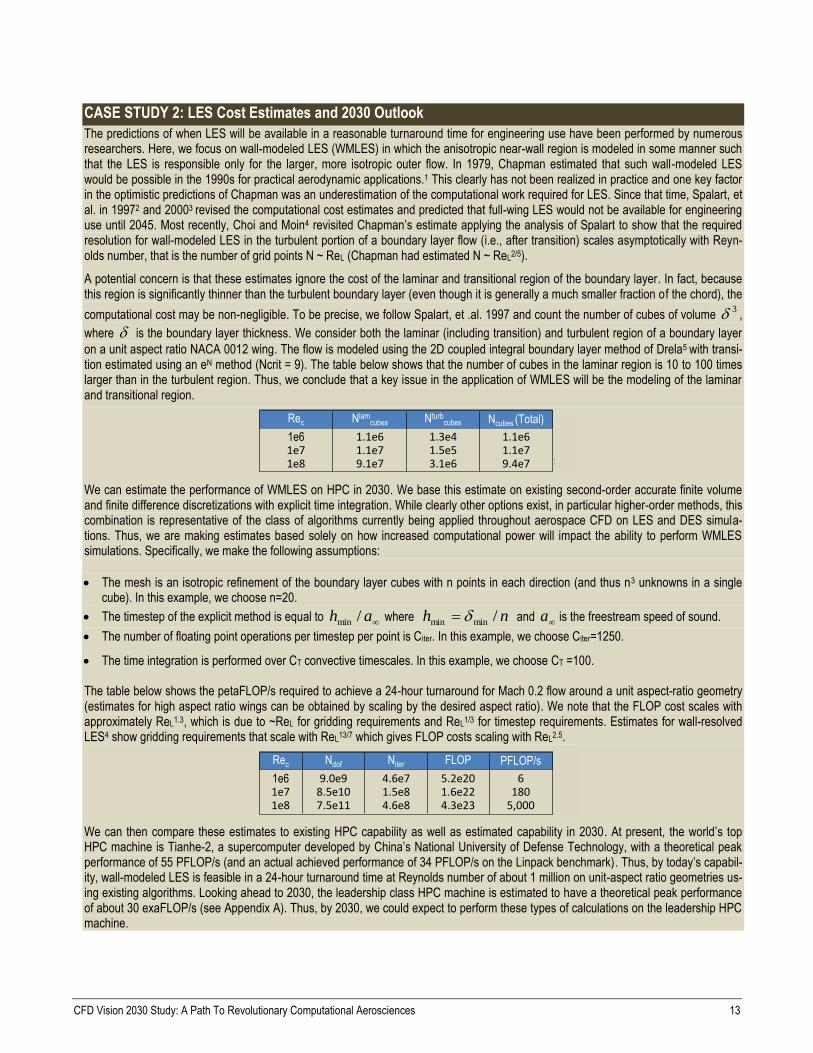
CASE STUDY 2: LES Cost Estimates and 2030 Outlook
The predictions of when LES will be available in a reasonable turnaround time for engineering use have been performed by numerous researchers. Here, we focus on wall-modeled LES (WMLES) in which the anisotropic near-wall region is modeled in some manner such that the LES is responsible only for the larger, more isotropic outer flow. In 1979, Chapman estimated that such wall-modeled LES would be possible in the 1990s for practical aerodynamic applications.1 This clearly has not been realized in practice and one key factor in the optimistic predictions of Chapman was an underestimation of the computational work required for LES. Since that time, Spalart, et al. in 19972 and 20003 revised the computational cost estimates and predicted that full-wing LES would not be available for engineering use until 2045. Most recently, Choi and Moin4 revisited Chapman’s estimate applying the analysis of Spalart to show that the required resolution for wall-modeled LES in the turbulent portion of a boundary layer flow (i.e., after transition) scales asymptotically with Reyn-olds number, that is the number of grid points N ~ ReL (Chapman had estimated N ~ ReL2/5).
A potential concern is that these estimates ignore the cost of the laminar and transitional region of the boundary layer. In fact, because this region is significantly thinner than the turbulent boundary layer (even though it is generally a much smaller fraction of the chord), the
computational cost may be non-negligible. To be precise, we follow Spalart, et .al. 1997 and count the number of cubes of volume 3 ,
where is the boundary layer thickness. We consider both the laminar (including transition) and turbulent region of a boundary layer
on a unit aspect ratio NACA 0012 wing. The flow is modeled using the 2D coupled integral boundary layer method of Drela5 with transi-tion estimated using an eN method (Ncrit = 9). The table below shows that the number of cubes in the laminar region is 10 to 100 times larger than in the turbulent region. Thus, we conclude that a key issue in the application of WMLES will be the modeling of the laminar and transitional region.
255606.004.ppt
Rec Nlamcubes Nturb
cubes Ncubes (Total)
1e6 1.1e6 1.3e4 1.1e61e7 1.1e7 1.5e5 1.1e71e8 9.1e7 3.1e6 9.4e7
We can estimate the performance of WMLES on HPC in 2030. We base this estimate on existing second-order accurate finite volume and finite difference discretizations with explicit time integration. While clearly other options exist, in particular higher-order methods, this combination is representative of the class of algorithms currently being applied throughout aerospace CFD on LES and DES simula-tions. Thus, we are making estimates based solely on how increased computational power will impact the ability to perform WMLES simulations. Specifically, we make the following assumptions:
The mesh is an isotropic refinement of the boundary layer cubes with n points in each direction (and thus n3 unknowns in a single cube). In this example, we choose n=20.
The timestep of the explicit method is equal to ah /min where nh /minmin and a is the freestream speed of sound.
The number of floating point operations per timestep per point is Citer. In this example, we choose Citer=1250.
The time integration is performed over CT convective timescales. In this example, we choose CT =100. The table below shows the petaFLOP/s required to achieve a 24-hour turnaround for Mach 0.2 flow around a unit aspect-ratio geometry (estimates for high aspect ratio wings can be obtained by scaling by the desired aspect ratio). We note that the FLOP cost scales with approximately ReL1.3, which is due to ~ReL for gridding requirements and ReL1/3 for timestep requirements. Estimates for wall-resolved LES4 show gridding requirements that scale with ReL13/7 which gives FLOP costs scaling with ReL2.5.
255606.005.ppt
Rec Ndof Niter PFLOP/s
1e6 9.0e9 4.6e7 61e7 8.5e10 1.5e8 1801e8 7.5e11 4.6e8 5,000
FLOP
5.2e201.6e224.3e23
We can then compare these estimates to existing HPC capability as well as estimated capability in 2030. At present, the world’s top HPC machine is Tianhe-2, a supercomputer developed by China’s National University of Defense Technology, with a theoretical peak performance of 55 PFLOP/s (and an actual achieved performance of 34 PFLOP/s on the Linpack benchmark). Thus, by today’s capabil-ity, wall-modeled LES is feasible in a 24-hour turnaround time at Reynolds number of about 1 million on unit-aspect ratio geometries us-ing existing algorithms. Looking ahead to 2030, the leadership class HPC machine is estimated to have a theoretical peak performance of about 30 exaFLOP/s (see Appendix A). Thus, by 2030, we could expect to perform these types of calculations on the leadership HPC machine.

CFD Vision 2030 Study: A Path To Revolutionary Computational Aerosciences 14
Additional conclusions based on these results are:
For the higher aspect ratios that are more relevant to external flows, the costs will be an order of magnitude larger and thus out of the reach of even 2030 leadership HPC machines at the high Reynolds numbers of interest.
At lower Reynolds numbers, the cost differences between wall-modeled and wall-resolved LES disappear. Thus, for lower Reynolds number applications, e.g., in some components of turbomachinery, wall-resolved LES is feasible on leadership class machines today.6
As additional complexities are introduced, e.g., the full geometric complexity of a turbomachinery or a high-lift configuration, the cost will increase further.
The cost estimate assumes that the laminar and transition regions are simulated using the same resolution (per cube) as in the turbulent region, i.e., the transition process is simulated. If the transition process could instead be modeled so that the grid resolution was essen-tially that required for steady laminar boundaries, then the cost of the laminar and transition region would become negligible compared to the turbulent region and reduces the above cost estimates by a factor of 10 to 100.
The wall modeling for this type of LES is a current weakness that could limit the reliability of using this approach for separation predic-tion.
While these types of LES calculations may be feasible on leadership class HPC machines, engineering CFD calculations are not often pursued at this level of parallelism. Rather, engineering CFD calculations tend to be performed with 1,000s and rarely 10,000s of com-pute nodes. Thus, to realize these capabilities will require effort to exploit existing and future HPC performance.
The potential impact of algorithmic work could be significant. For example, a 10-fold improvement due to algorithmic performance (e.g., through adaptivity, or higher-order discretizations, or improved solution algorithms) could bring these 24-hour calculations down to a few hours. Further, this could relieve some of the pressure on wall modeling and transition modeling by facilitating increased grid resolution (or improved accuracy at less cost), and head toward wall-resolved LES.
1. Chapman, D. R., “Computational Aerodynamics Development and Outlook,” AIAA J. 17, 1293 (1979) 2. Spalart, P. R., Jou, W.-H., Strelets, M., & Allmaras, S. R., “Comments on the feasibility of LES for wings, and on a hybrid RANS/LES approach” (invited). First
AFOSR Int. Conference on DNS/LES, Aug. 4-8, 1997, Ruston, Louisiana. (In “Advances in DNS/LES,” C. Liu & Z. Liu Eds., Greyden Press, Columbus, OH). 3. Spalart, P. R., “Strategies for turbulence modeling and simulations,” Int. J. Heat Fluid Flow 21, 252-263., 2000. 4. Choi, H., and Moin, P., “Grid-point requirements for large eddy simulation: Chapman’s estimates revisited,” Phys. Fluids 24, 011702 (2012) 5. Mueller, T. J. (ed.), Low Reynolds Number Aerodynamics, Lecture Notes in Engineering, Volume 54, 1989, pp 1-12. 6. Tucker, P. G., “Computation of unsteady turbomachinery flows: Part 2-LES and hybrids”, Progress in Aerospace Sciences. ISSN 0376-0421, 2011
3. Effects of grid resolution and solution scheme in as-
sessing turbulence models. A key gap in the effective-
ness of current and future turbulence models is the effect
of grid resolution and solution scheme on both the accu-
racy and convergence properties of the models. Studies
show that adequate grid resolution is required to capture
the full range of turbulence structures in models ranging
from simple eddy-viscosity formulations to full LES and
DNS simulations.55
Additionally, choice of solution
scheme may be important when using marginal grid res-
olution for complex geometries. Much work has been
performed on building-block geometries,23,65
but real-
world cases are now too complex to assess full grid con-
vergence.56
4. Insufficient use of foundational validation/ calibra-
tion datasets to drive physics-based improvements to
turbulence prediction. Key experimental datasets are
critically important in the ongoing development and re-
finement of the full range of turbulence models from
RANS to LES. Typical impediments include test cost,
large number of cases needed, and instrumentation limi-
tations. Moreover, many existing datasets are often not
effectively exploited to use all available data in assessing
and improving models.
5. Insufficient use of real-world experiments to validate
turbulence models. In addition to building-block exper-
iments, more specific test data from complex, integrated
flow fields using geometries that are more representative
of complex aerospace systems is needed. Impediments
include balancing test cost and model complexity, diffi-
culty in designing experiments, geometry deviations,
measurement detail, and accuracy of CFD.
6. Robust transition prediction capability. Boundary
layer transition is not well predicted (if at all) in CFD
practice, impacting wind tunnel to flight scaling, laminar
flow prediction and control, turbomachinery design, and
hypersonic transition/heating analysis, among others.
Transition modeling for lower Reynolds number appli-
cations is particularly lacking, with specific impact on
high bypass ratio turbomachinery and for the lower
Reynolds number vehicles being designed today. Cur-
rently, en methods are difficult to use. However, there
have been some novel and promising developments in
transition prediction methods (e.g., the Langtry-Menter
correlation-based model),50
but these partial-differential
equation (PDE) based methods (as opposed to en tech-
niques) must be calibrated for a wide range of flow re-
gimes and problems of interest, and should be viewed as
in-development and somewhat risky. Still, these meth-
ods are being improved and are propagating into both
government and commercial CFD codes72
even as they
(currently) do not account for the cross-flow mode of

CFD Vision 2030 Study: A Path To Revolutionary Computational Aerosciences 15
transition. Solid research is needed both on the PDE and
en tracks, with emphasis on both accuracy and ease of
coupling with RANS codes.
7. Lack of explicit collaboration among turbulence
researchers. There is a general lack of close coordina-
tion between turbulence modelers and researchers both
in the aerospace field itself (scattered amongst academ-
ia, industry, and government), and between researchers
in aerospace and related fields. In order to generate the
new ideas necessary to address the key issues of flow
separation and transition, it is imperative that a more
concerted effort be undertaken to connect members of
the aerospace turbulence community to others in
weather prediction, bio-fluids, and hydrodynamic
fields.
5.3 Autonomous and Reliable CFD Simulation
Today, most standard CFD analysis processes for the simu-
lation of geometrically complex configurations are onerous,
both in terms of cycle time and process robustness. Even
for simpler configurations that are typically analyzed during
the conceptual design phase, full automation is essential in
order for a conceptual designer to effectively exploit the
capacity of high performance computers and physics-based
simulation tools. Based on feedback from the engineering
and scientific communities as determined through our CFD
Vision 2030 survey and workshop, the key issues related to
CFD automation and reliability can be categorized into the
broad areas of mesh generation and adaptivity, discretiza-
tions, solvers and numerics, and error control and uncertain-
ty quantification.
Mesh generation and adaptivity
Today, the generation of suitable meshes for CFD simula-
tions about complex configurations constitutes a principal
bottleneck in the simulation workflow process. Often the
mesh generation phase constitutes the dominant cost in
terms of human intervention, and concerns about the cost
and reliability of mesh generation were raised repeatedly in
the survey and workshop. However, since a computational
mesh is merely a means to enable the CFD simulation, ul-
timately the mesh generation process should be invisible to
the CFD user or engineer. Given a suitable geometry repre-
sentation and a desired level of solution accuracy, a fully
automated meshing capability would construct a suitable
mesh and adaptively refine this mesh throughout the solu-
tion process with minimal user intervention until the final
accuracy levels are met. This process allows the user to
focus on the final solution without concern for the construc-
tion and maintenance of the underlying mesh. Achieving
this vision of fully automated meshing requires overcoming
various important current impediments.
1. Inadequate linkage with CAD. Configuration geome-
try definitions required by mesh generation software
are generally provided by computer-aided design
(CAD) packages. However, there is currently no single
standard for representing surface or solid geometries
within CAD tools, complicating efforts to fully auto-
mate the link between mesh generation and geometry
definition. Furthermore, many existing CAD geometry
definitions are poorly suited for CFD analyses, either
due to insufficient accuracy (non water-tight geome-
tries often adequate for manufacturing purposes), or
due to excessive detail not essential for the CFD analy-
sis. This results in the need to incorporate specialized
post-processing tools such as shrink-wrapping in the
former case, and/or de-featuring techniques in the latter
case. At the same time, additional information such as
slope and curvature or even higher surface derivatives
may be required for the generation of curved mesh el-
ements suitable for use with higher-order accurate CFD
discretizations.73,74
Finally, for adaptive meshing pur-
poses, tight coupling between the CFD software and
geometry definition is required to enable low-overhead,
on-demand, geometry surface information queries
within the context of a massively parallel computing
framework.75
2. Poor mesh generation performance and robustness.
Significant human intervention is often required in the
mesh generation process due to lack of robustness. This
is evidenced by the inability of current mesh generation
software to consistently produce valid high-quality
meshes of the desired resolution about complex configu-
rations on the first attempt. Additionally, many current
mesh generation algorithms (e.g., advancing-front meth-
ods) do not scale appropriately on parallel computer ar-
chitectures, and most mesh generation software is either
run sequentially, or using a small number of computer
cores or processors. On the other hand, CFD solver
technology has demonstrated very good scaling on mas-
sively parallel machines,76-78
and is demanding ever
larger meshes, which the mesh generation community is
finding increasingly difficult to deliver due both to
memory and time constraints using desktop commodity
hardware. During the last decade or more, developments
in mesh generation software came from third-party
commercial vendors and NASA investment in this area
has essentially evaporated. However, fundamental ad-
vances in computational geometry and other areas will
be key to improving the reliability, robustness, and par-
allel scalability of mesh generation capabilities, particu-
larly as larger simulations using finer meshes about more
complex geometries are sought. Additionally, paradigm
shifts in meshing technology (i.e., cut cell methods,
strand grids, meshless methods) may lead to revolution-
ary advances in simulation capabilities.79-82
Discretizations, Solvers, and Numerics
The core of an autonomous and reliable CFD capability
must rely on efficient and robust discretization and solution

CFD Vision 2030 Study: A Path To Revolutionary Computational Aerosciences 16
strategies. Discretizations must be tolerant of localized poor
mesh quality while at the same time be capable of deliver-
ing high accuracy at low cost. Solution techniques must be
scalable, efficient, and robust enough to deliver converged
solutions under all reasonable conditions with minimal user
intervention. One of the principal concerns raised through-
out our survey and workshop was the high level of expertise
and human intervention often required for performing and
understanding CFD analyses, with a consensus that a prin-
cipal requirement for relieving this dependency will require
added investment in basic numerical methods research.
Current gaps and impediments with numerical methods
include:
1. Incomplete or inconsistent convergence behavior.
Most current CFD codes are capable of producing fully
converged solutions in a timely manner for a variety of
simple flow problems. However, most often these same
tools are less reliable when applied to more complex
flow fields and geometries,56,85
and may fail, or require
significant user intervention to obtain adequate results.
There are many possible reasons for failure, ranging
from poor grid quality to the inability of a single algo-
rithm to handle singularities such as strong shocks, un-
der-resolved features, or stiff chemically reacting terms.
What is required is an automated capability that delivers
CASE STUDY 3: Scalable Solver Development
The development of optimal solvers has been central to the success of CFD methods since the early days of numerical simulation, for both steady-state and time-implicit problems. Optimal solvers are defined as methods that are capable of computing the solution to a problem with N unknowns in O(N) operations. Because the number of unknowns in industrial CFD problems is most often very large (106 < N < 109), optimal solvers offer the potential for orders of magnitude increase in solution efficiency compared to simple iterative solvers, which most often scale as O(N2) or higher.
Multigrid methods constitute the most successful and widely used optimal solvers for CFD problems. These methods were developed for CFD applications at an early stage, with considerable NASA investment. In the late 1970s, joint NASA collab-orative work with academic leaders in multigrid solver technology produced some of the first successful multigrid solvers for potential flow methods1, followed by efficient multigrid solvers for the Euler equations2, and the Na-vier-Stokes equations. The success was such that multigrid methods were implemented and used in virtually all important NASA CFD codes, including TLNS3D, CFL3D, OVERFLOW, and more recently FUN3D. Multigrid methods have become essential solver components in commercial production codes such as Fluent and STARCCM+, and have received particular attention within the DOE where they are used in various large-scale production codes. Despite their early success, many impediments remain for successfully extending these solv-ers to larger and more complex problems. While most early NASA investment focused on geometric multigrid for structured meshes, ex-tending these solvers to complex geometry CFD problems or even abstract matrix inversion problems requires the development of alge-braic multigrid methods (AMG). At the same time, improvements to current multigrid strategies are required if these methods are to scale effectively on emerging massively parallel HPC hardware. Although NASA investment in further research on multigrid methods has stalled since the early 1990s, considerable research has been directed toward developing more optimal AMG solvers designed for use on petascale and exascale hardware within the DOE. For example, the Scalable Linear Solver group at Lawrence Livermore Na-tional Laboratory has developed parallel AMG technology and related methods such as Smoothed Aggregation techniques that maintain optimal solver qualities while delivering vastly improved scalability on massively parallel machines. Current capabilities include the demonstration of the solution of a problem involving over 1012 degrees of freedom with good scalability on over 100,000 cores.3 Alt-hough these solvers are publicly available, they have not drawn the interest of the aerospace CFD community, and will likely require considerable investment to modify and extend to production aerospace CFD problems.
Multigrid method developments are often reported at dedicated multigrid specialist conferences. For example, the first successful multi-grid solution of the Euler equations was reported at the 1983 Copper Mountain Multigrid Methods conference.2 This conference series was traditionally well attended by NASA participants and, as recently as 1996, the conference proceedings were edited and published by NASA Langley4. However, during the last decade there has been virtually no NASA presence at these conferences. This has been accompanied by a significant decline of scalable solver papers published in AIAA venues, while NASA CFD codes have remained con-fined to the same multigrid technology that was developed in those early years.
1. South, J. C. and Brandt, A., “Application of a Multi-level Grid Method to Transonic Flow Calculations,” in Transonic Flow Problems in Turbomachinery, (Adam, T.C. and Platzer, M.F. eds.) Hemisphere, Washington, pp 180-207, 1977
2. Jameson, A., “Solution of the Euler Equations for Two Dimensional Transonic Flow by a Multigrid Method,” Proceedings of International Multigrid Conference, Cop-per Mountain, April 1983, Applied Mathematics and Computation, Vol. 13, 1983, pp. 327-356.
3. Baker, A. H., Falgout, R. D., Kolev, Tz. V., and Yang, U. M., “Scaling Hypre’s Multigrid Solvers to 100,000 Cores,” in High Performance Scientific Computing: Algo-rithms and Applications, M. Berry, et al., eds., Springer (2012). LLNL-JRNL-479591.
4. Melson, N. D., Manteuffel, T. A., McCormick, S. F., Douglas, C. C. (eds.), “Seventh Copper Mountain Conference on Multigrid Methods,” NASA CP 3339, Septem-ber 1996.

CFD Vision 2030 Study: A Path To Revolutionary Computational Aerosciences 17
hands-off solid convergence under all reasonable antici-
pated flow conditions with a high tolerance to mesh ir-
regularities and small-scale unsteadiness. Reaching this
goal necessarily will require improvements in both dis-
cretizations and solver technology,86
since inadequate
discretizations can permit unrealizable solutions, while
temperamental solvers may be unable to reach existing
valid solutions. Although incremental improvements to
existing algorithms will continue to improve overall ca-
pabilities, the development of novel robust numerical
techniques such as monotone, positivity-preserving,
and/or entropy-preserving schemes87,88
and their exten-
sion to complex problems of industrial relevance offers
the possibility of radical advances in this area.
2. Algorithm efficiency and suitability for emerging
HPC. In previous decades, NASA has invested heavily
in numerics and solver technology, and it is well doc-
umented that equivalent advances in numerical simula-
tion capability have been enabled through the devel-
opment of more efficient algorithms compared to ad-
vances in HPC hardware.1,16-18
However, during the last
decade, algorithmic investment has been dramatically
curtailed, with the result that the many flow solvers in
use today were developed more than 20 years ago and
are well known to be suboptimal. Because solver opti-
mality is an asymptotic property, as larger simulations
are attempted, the potential benefits of better solvers
grow exponentially, possibly delivering orders of mag-
nitude improvement by the exascale computing
timeframe. At the same time, the drive to more com-
plex flows (including more complex turbulence mod-
els, stiff chemically reacting terms, or other effects)
and tightly coupled multidisciplinary problems will re-
quire the development of novel techniques that remain
stable and efficient under all conditions. Finally, exist-
ing numerical techniques were never conceived with
massive parallelism in mind, and are currently unable
to capitalize on the emerging massively parallel and
heterogeneous architectures that are becoming the
mainstay of current and future HPC. In order to im-
prove simulation capability and to effectively leverage
new HPC hardware, foundational mathematical re-
search will be required in highly scalable linear and
nonlinear solvers not only for commonly used discreti-
zations but also for alternative discretizations, such as
higher-order techniques.89
Beyond potential advantages
in improved accuracy per degree of freedom, higher-
order methods may more effectively utilize new HPC
hardware through increased levels of computation per
degree of freedom.
Error control and uncertainty quantification
Errors in current CFD simulations are not well understood
or well quantified, including errors due to spatial and tem-
poral discretization, incomplete convergence, and the phys-
ical models and parameters they embody. The lack of error
quantification raises the risk that engineering decisions are
based on inaccurate and/or uncertain results. The Vision
2030 survey highlighted the need for improvements in error
quantification. Furthermore, in terms of reliable and auto-
mated CFD simulations, discretization error estimation is a
key ingredient for the realization of a solution adaptive pro-
cess. Current error control and uncertainty quantification
gaps and impediments include:
1. Limited use of existing error estimation and control
methods. Significant progress has been made in the es-
timation and control of discretization errors, in particu-
lar in terms of output-based techniques.90-93
However,
while these techniques were demonstrated by multiple
groups for steady 2D RANS94
and 3D inviscid flows,83
the applications to 3D RANS and unsteady flows were
limited, in particular for complex geometries. These
more complex applications have been severely imped-
ed by the inadequacies of 3D anisotropic and time-
dependent adaptive meshing, as well as by poor ro-
bustness of current discretization and solution algo-
rithms (i.e., to be able to solve flow and adjoint equa-
tions on potentially poor quality meshes during the
adaptive process).
2. Inadequacy of current error estimation techniques.
While discretization error estimation techniques for
outputs have improved during the past 10 years, these
techniques do have fundamental limitations that could
influence their application to increasingly complex
problems. In particular, output-based error estimation
techniques are based on linearizations about existing
(approximate) solutions and as a result can have signif-
icant error when the flows are under resolved (even in
the case of a linear problem, the techniques generally
only provide error estimates and are not bounds on the
error). Furthermore, for unsteady, chaotic flows (which
will be a key phenomenon of interest as turbulent DES
and LES simulations increase in use moving forward)
linearized analysis will produce error estimates that
grow unbounded with time (due to the positive Lya-
punov exponent for chaotic flows).95,96
In these situa-
tions, existing output-based methods will be swamped
by numerical error, rendering the sensitivity infor-
mation meaningless. This issue will affect not only er-
ror estimation but also design optimization moving
forward.
3. Limited use of uncertainty quantification. The con-
sideration of uncertainty due to parametric variability as
well as modeling error raises significant challenges. Var-
iability and uncertainty of inputs (boundary and initial
conditions, parameters, etc.) to fluid dynamic problems
are largely unquantified. Even if estimates are available
and/or assumed, the propagation of these uncertainties
poses a significant challenge due to the inherent cost, the
lack of automation and robustness of the solution pro-
cess, and the poor utilization of high performance com-

CFD Vision 2030 Study: A Path To Revolutionary Computational Aerosciences 18
puting. Even more challenging is the quantification of
modeling error. This will likely require significantly
more expensive methods (e.g., based on Bayesian ap-
proaches).97
While uncertainty quantification is being
investigated in the broad research community, most no-
tably through DOE and NSF led programs,98
the engi-
neering community, and the aerospace community in
particular, have had minimal investments to address
these issues.
5.4 Knowledge Extraction and Visualization
An integral part of effectively using the advanced CFD
technology envisioned in 2030 is the way in which the very
large amount of CFD-generated data can be harvested and
utilized to improve the overall aerodynamic design and
analysis process. The resulting utilization of this data would
include insight into pertinent flow physics, use with aero-
dynamic or multidisciplinary optimization, and generation
of effective databases for a myriad of purposes, including
control law development, loads assessment,
flight/performance simulation, etc.
A number of technology gaps and impediments in the area
of knowledge extraction for large-scale CFD databases and
simulations must be overcome to efficiently analyze and
utilize CFD simulations in the 2030 time frame.
1. Effective use of a single, high-fidelity CFD simula-
tion. As high-performance computing (HPC) systems
become faster and more efficient, a single unsteady CFD
simulation using more complicated physical models
(e.g., combustion) to solve for the flow about a complete
aerospace system (e.g., airplane with full engine simula-
tion, space vehicle launch sequence, aircraft in maneu-
vering flight, etc.) using a much higher number of grid
points (~10 to 100 billion) will become commonplace in
the 2030 time frame. Effective use (visualization and in-
situ analysis) of these very large, single, high-fidelity
CFD simulations will be paramount.99
Similarly, higher-
order methods will likely increase in utilization during
this time frame, although currently the ability to visual-
ize results from higher order simulations is highly inade-
quate. Thus, software and hardware methods to handle
data input/output (I/O), memory, and storage for these
simulations (including higher-order methods) on emerg-
ing HPC systems must improve. Likewise, effective
CFD visualization software algorithms and innovative
information presentation (e.g., virtual reality) are also
lacking.
2. Real-time processing and display of many high-
fidelity CFD simulations. By the year 2030, HPC ca-
pabilities will allow for the rapid and systematic gener-
ation of thousands of CFD simulations for flow physics
exploration, trend analysis, experimental test design,
design space exploration, etc. The main goal, therefore,
is to collect, synthesize, and interrogate this large array
of computational data to make engineering decisions in
real time.39
This is complicated by a lack of data stand-
ards which makes collection and analysis of results
from different codes, researchers and organizations dif-
ficult, time consuming and prone to error. At the same
time, there are no robust, effective techniques for distil-
ling the important information contained in large col-
lections of CFD simulation data into reduced-order
models or meta-models that can be used for rapid pre-
dictive assessments of operational scenarios, such as
the correlation of flow conditions with vehicle perfor-
mance degradation or engine component failures, or
assessments of engineering tradeoffs as required in typ-
ical design studies.100
3. Merging of high fidelity CFD simulations with other
aerodynamic data. With wind tunnel and flight-testing
still expected to play a key role in the aerospace system
design process, methods to merge and assimilate CFD
and multidisciplinary simulation data with other multi-
fidelity experimental/computational data sources to
create an integrated database, including some measure
of confidence level and/or uncertainty of all (or indi-
vidual) portions of the database, are required. Current-
ly, the merging of large amounts of experimental and
variable fidelity computational data is mostly carried
out through experience and intuition using fairly unso-
phisticated tools. Well founded mathematically and sta-
tistically based approaches are required for merging
such data,101-103
for eliminating outlier numerical solu-
tions, as well as experimental points, and for generally
quantifying the level of uncertainties throughout the
entire database in addition to at individual data
points.104
5.5 Multidisciplinary/Multiphysics Simulations
and Frameworks
We also assume that CFD capabilities in 2030 will play a
significant role in routine, multidisciplinary analysis
(MDA) and optimization (MDAO) that will be typical of
engineering and scientific practice. In fact, in 2030 many of
the aerospace engineering problems of interest will be of a
multidisciplinary nature and CFD will have to interface
seamlessly with other high-fidelity analyses including
acoustics, structures, heat transfer, reacting flow, radiation,
dynamics and control, and even ablation and catalytic reac-
tions in thermal protection systems. With increasingly
available computer power and the need to simulate com-
plete aerospace systems, multidisciplinary simulations will
become the norm rather than the exception. However, effec-
tive multidisciplinary tools and processes are still in their
infancy.
Limitations on multidisciplinary analyses fall under various
categories including the setup and execution of the anal-
yses, the robustness of the solution procedures, the dearth
of formal methodologies to guarantee the stability and accu-
racy of coupled high-fidelity simulations, and the lack of

CFD Vision 2030 Study: A Path To Revolutionary Computational Aerosciences 19
existing standards for multidisciplinary coupling. The result
tends to be one-off, laborious, and nonstandard interfaces
with other disciplines with dubious accuracy and stability.
Multidisciplinary optimizations inherit all of these limita-
tions and suffer from additional ones of their own, includ-
ing the inability to produce accurate discipline and system-
level sensitivities, the lack of quantified uncertainties in the
participating models, the lack of robustness in the system-
level optimization procedures, as well as very slow turna-
round times.
The vision for 2030 MDA/O involves the seamless setup
and routine execution of both multidisciplinary analyses
and optimizations with
Rapid turnaround (hours for MDA and less than a day
for MDO).
User-specified accuracy of coupled simulations.
Robustness of the solution methodology.
Ability to provide sensitivity and uncertainty infor-
mation.
Effective leveraging of future HPC resources.
For this vision to proceed forward, the development of mul-
tidisciplinary standards will be necessary, as well as the
creation of coupling frameworks that facilitate the multidis-
ciplinary interactions envisioned here. Moreover, key re-
search challenges in multidisciplinary coupling, computa-
tion of system-level sensitivities, management of uncertain-
ties in both the analyses and optimizations, hierarchical
decomposition of the optimization problems, and both au-
tomation and standardization processes will need to be
overcome.
More specifically, a number of technology gaps and imped-
iments must be tackled to enable truly multidisciplinary
analyses and optimizations in the 2030 timeframe. In this
report, we focus on the requirements that affect 2030 CFD.
Although, by extension, we also discuss some more general
gaps and impediments that are likely to affect our vision.
1. Robustness and automation of CFD analyses in
multidisciplinary environments. To ensure that 2030
CFD can be an integral part of routine multidiscipli-
nary, multiphysics simulations, the manpower cost re-
quired to set up and execute such calculations must be
drastically reduced. Firstly, the setup of high-fidelity
multidisciplinary analyses must be largely automated
including all operations involving surface and volume
grid transfers and interpolations, grid deformations
and/or re-generation, information exchanges, and map-
pings to HPC environments. Secondly, the execution of
multiphysics simulations that involve Vision 2030
CFD must include appropriate measures to ensure the
robustness of the solution procedure, protecting against
coupled simulation failure and including the on-
demand availability of all necessary modules in the
CFD chain so that CFD failure modes are protected.
Such automation and robustness characteristics provide
the foundation for more complex problems that require
the solution of multidisciplinary simulations.
2. The science of multidisciplinary coupling at high
fidelity. Exchanges of information between Vision
2030 CFD and other disciplinary solvers with which
CFD will need to interact will require assurances of
both accuracy and stability. Such properties often re-
quire the satisfaction of conservation principles to
which close attention must be paid.105
Moreover, with-
in the context of nonlinear phenomena and unsteady
flows, the proper interfacing between CFD and other
codes requires significant effort and can be hard to
generalize. The development of libraries and proce-
dures that enable high fidelity, accurate, and stable
couplings, regardless of the mesh topologies and char-
acteristic mesh sizes must be pursued. Such software
may also need to be cognizant of the discretization de-
tails of the CFD solver. Ultimately, solvers using dis-
cretizations of a given accuracy (in space and in time),
when coupled to other solvers, must ensure that the ac-
curacy of the component solvers is preserved and that
the coupling procedure does not give rise to numerical
errors that may manifest themselves through solution
instabilities.106
3. Availability of sensitivity information and propaga-
tion of uncertainties. Vision 2030 CFD is expected to
interact with other solvers (for different disciplines) in
multidisciplinary analyses and optimizations. In 2030,
the state of the art is presumed to include the quantifi-
cation of uncertainties (UQ), at the system level, aris-
ing from uncertainties in each of the participating dis-
ciplines. In order to facilitate both optimization and UQ
at the system level, Vision 2030 CFD must be able to
provide sensitivities of multiple derived quantities of
interest with respect to large numbers of independent
parameters at reasonable computational cost. Novel
techniques for the propagation of uncertainties will
need to be embedded into 2030 CFD for more compre-
hensive treatment of UQ problems. Moreover, the sup-
port for system-level sensitivity information and UQ
will demand the availability of derivative and UQ in-
formation related to outputs of CFD that may be uti-
lized by other solvers. Ensuring that these capabilities
are present in our Vision 2030 CFD will permit ad-
vanced analyses, optimizations, and UQ to be carried
out.
4. Standardization and coupling frameworks. Owing
to the multitude of disciplinary solvers available for
coupling with 2030 CFD, the uncertainty regarding the
actual code structure, HPC solver architecture, and in-
ternal solution representation, it is fundamental to en-
sure that multidisciplinary simulation standards (such
as the CGNS standard107
created for CFD) are created
so that a variety of solvers can participate in multidis-
ciplinary analyses and optimizations. Beyond the typi-

CFD Vision 2030 Study: A Path To Revolutionary Computational Aerosciences 20
cal codification of the inputs and outputs of a particular
physical simulation, standards for MDAO may need to
include sensitivities, uncertainties, and overall descrip-
tions of the parameterization (possibly including the
geometry itself) and the optimization problem. To ena-
ble tight coupling of diverse disciplines and codes, the
data standards need to extend to include memory resi-
dent information and coding structures.57,59,60
6 Technology Development Plan
To achieve our vision of CFD in 2030 and directly address
the key CFD technology shortcomings and impediments
that currently limit the expanded use of CFD methods with-
in the aerospace analysis and design process, a comprehen-
sive CFD development plan has been developed and is pre-
sented in this section. In order to place future technology
developments within the context of our Vision for 2030
CFD, we first describe in more detail a number of Grand
Challenge (GC) problems that embody the goals for CFD in
2030. Next, a comprehensive roadmap that depicts key
technology milestones and demonstrations needed to sup-
port the GC simulations is introduced and described. An
integrated research plan is then proposed. Finally, an over-
all research strategy with specific recommendations for
executing the plan to advance the state of the art in CFD
simulation capability is provided.
6.1 Grand Challenge Problems
The intent of the GC problems is to drive the identification
and solution of the critical CFD barriers that would lead to a
desired revolutionary CFD capability. We purposely have
chosen GC problems that are bold, recognizing that they may
not be routinely achievable by 2030, but, if achieved, would
represent critical step changes in engineering design capabil-
ity. To this end, the GC cases are chosen to encompass the
CFD capabilities required to design and analyze advanced air
and space vehicles and systems in 2030, and represent im-
portant application areas of relevance to the various NASA
aeronautics and space missions. Details on each of the four
GC problems are given below.
Grand Challenge Problem 1:
LES of a powered aircraft configuration across the full
flight envelope. This case focuses on the ability of CFD to
simulate the flow about a complete aircraft geometry at the
critical corners of the flight envelope including low-speed
approach and takeoff conditions, transonic buffet, and pos-
sibly undergoing dynamic maneuvers, where aerodynamic
performance is highly dependent on the prediction of tur-
bulent flow phenomena such as smooth body separation
and shock-boundary layer interaction. Clearly, HPC ad-
vances alone will not be sufficient to solve this GC prob-
lem and improvements in algorithmic technologies or other
unforeseen developments will be needed to realize this
goal. Progress toward this goal can be measured through
the demonstration of effective hybrid RANS-LES and
wall-modeled LES simulations with increasing degrees of
modeled versus resolved near-wall structures with increas-
ing geometric complexity. Fully optimized flow solvers
running on exascale computing platforms will also be criti-
cal.
Grand Challenge Problem 2:
Off-design turbofan engine transient simulation. This
case encompasses the time-dependent simulation of a
complete engine including full-wheel rotating components,
secondary flows, combustion chemistry, and conjugate
heat transfer. This GC will enable virtual engine testing
and off-design characterization including compressor stall
and surge, combustion dynamics, turbine cooling, and en-
gine noise assessment. Similar to GC 1, demonstration of
advances in accurate prediction of separated flows, com-
plex geometry, sliding and adaptive meshes, and nonlinear
unsteady flow CFD technologies will be required to
achieve this goal. In addition, advances in the computation
of flows of widely varying time scales, and the predictive
accuracy of combustion processes and thermal mixing, will
be necessary.
Grand Challenge Problem 3:
MDAO of a highly flexible advanced aircraft configu-
ration. The increased level of structural flexibility that is
likely to be present in future commercial aircraft configu-
rations (of the N+3 and N+4 types envisioned by NASA
and its partners) dictates a system-level design that re-
quires the tight coupling of aerodynamics, structures, and
control systems into a complete aero-servo-elastic analysis
and design capability. This GC problem focuses on the
multidisciplinary analysis and optimization of such config-
urations including explicit aeroelastic constraints that may
require a time-accurate CFD approach. In addition to the
aero-servo-elastic coupling, this GC includes the integra-
tion of other disciplines (propulsion and acoustics) as well
as a full mission profile. The ultimate goal is to demon-
strate the ability (in both MDA and MDAO) to perform
CFD-based system-level optimization of an advanced con-
figuration that requires both steady and unsteady high-
fidelity models.

CFD Vision 2030 Study: A Path To Revolutionary Computational Aerosciences 21
CASE STUDY 4: Impact of CFD Tool Development on NASA Science and Space Exploration Missions
Traditionally, the development of physics-based simulation tools for aerospace vehicle analysis and design has been the responsibility of NASA’s Aeronautics Research Mission Directorate (ARMD), with an emphasis on solving ARMD’s aeronautics goals. However, NASA’s science and space exploration missions rely heavily on simulation tools. CFD has played a critical role in virtually all recent past and present NASA space vehicle programs, including Space Shuttle return to flight,1 entry-descent and landing (EDL) predictions for the entire series of Mars landings,2 support for the recent Constellation Program3 and, more recently, for the Multipurpose Crew Vehicle (MPCV) and the Space Launch System (SLS) programs. Throughout many of these efforts, limitations in numerical simulation tools for space vehicle design were uncovered, requiring expensive contingency planning. For example, the Ares I development, which employed a combination of wind-tunnel testing and CFD methods for aerodynamic database generation, found that CFD was often less reliable and more expensive than experimental testing, resulting in limited use of CFD principally in specific regions of the flight envelope where testing was not feasible.4 Similar conclusions were drawn by engineers developing the MPCV Orion aerodynamic database.
In a recent yearly review of NASA’s Aerosciences State-of-the-Discipline, NASA’s technical fellow for Aerosciences has assessed the ability of the discipline to support NASA’s missions, and identified these top three technical challenges:
Prediction of unsteady separated flows
Aero-plume interaction prediction
Aerothermal predictions
Accurate prediction of unsteady separated flow is critical in the design of launch vehicle sys-tems, where buffet and aeroacoustic fluctuating pressures in the transonic regime during as-cent can result in high vibrational environments. Currently, launch vehicle buffet environments are obtained almost exclusively through wind tunnel testing and correlation with empirical data at considerable expense and uncertainty, resulting in overly conservative structural mass and reduced payload to orbit. Advanced simulation techniques such as DES are beginning to be explored but have been found to be expensive and to require further refinement and validation. Similarly, quantifying the aeroacoustic environment in launch vehicle design due to separated flows and aero-plume interactions is an important consideration for flight qualification of vehicle electronic components and passenger safety. Previous vehicle programs such as Ares I have incurred considerable expense for the experimental determination of aeroacoustic environ-ments, while investigations by NASA have determined that current CFD techniques are inadequate for the prediction of launch vehicle aeroacoustic environments.5 However, the largest payoff in launch vehicle design would come from the use of CFD as a dynamic flight simulation capability, rather than a static aerodynamic database generation tool, as is currently the case, although little effort is being targeted toward this area. Accurate prediction of separated flows is also an important consideration for spacecraft EDL, which is com-pounded by the need for accurate aerothermal predictions, which in turn are hindered by the need for reliable transition prediction and the inclusion of other multiphysics considerations such as radiation and ablator performance. Accurate simulation of the aero-plume in-teractions of the reaction-control systems for bluff body re-entry is another area where the development of accurate simulation capabili-ties could reduce cost and uncertainties associated with complex experimental campaigns. Finally, the design and validation of space-craft decelerators, including high-speed parachutes and deployable decelerators would benefit enormously from the development of a reliable, nonempirical simulation capability, although this represents a complex nonlinear aero-structural problem with massive flow sep-aration that is well beyond current capabilities.
Clearly, there is a need for better simulation tools within NASA’s science and space exploration missions, as well as within aeronautics itself. Furthermore, many of the technological barriers are similar in both areas, such as the inability to accurately simulate separated flows and transition and the need to harness the latest HPC hardware, while other issues are more critical to the space mission such as aero-plume and aerothermal prediction capabilities. To overcome these deficiencies, increased coordination will be required between NASA’s science and space exploration programs, which are driving these requirements, and NASA aeronautics, where much of the ex-pertise for simulation method development resides. In the place of the current approach, which relies on the periodic assessment of ex-isting simulation tools, a longer term outlook that invests in new simulation capability development for specific space programmatic ob-jectives must be adopted.
1 Gomez, R. J., Aftosmis, M. J., Vicker, D., Meakin, R. L., Stuart, P. C., Rogers, S. E., Greathouse, J. S., Murman, S. M., Chan, W. M., Lee, D. E., Condon, G. L., and Crain, T., Columbia Accident Investigation Board (CAIB) Final Report. Vol. II, Appendix D.8. Government Printing Office, 2003.
2 Edquist, K. T., Dyakonov, A. A., Wrightz, M. J., and Tang, C. Y., “Aerothermodynamic Design of the Mars Science Laboratory Backshell and Parachute Cone,” AIAA paper, 2009-4078.
3 Abdol-Hamid, K. S., Ghaffari, F., and Parlette, E. B., “Overview of the Ares-I CFD Ascent Aerodynamic Data Development and Analysis based on USM3D,” AIAA paper, 2011-15, 49th AIAA Aerospace Sciences Meeting and Exhibit, Orlando, FL, January 2011.
4 Malik, M. R. and Bushnell, D., (eds.), “Role of Computational Fluid Dynamics and Wind Tunnels in Aeronautics R&D,” NASA TP 2012-217602, September 2012. 5 “Independent Assessment of External Pressure Field Predictions Supporting Constellation Program Aeroacoustics (ITAR),” NASA Engineering and Safety Center
Report NESC-RP-07-040, September 2013.

CFD Vision 2030 Study: A Path To Revolutionary Computational Aerosciences 22
Grand Challenge Problem 4:
Probabilistic analysis of a powered space access con-
figuration. The goal of this case is to provide a complete
description of the aerothermodynamic performance, in-
cluding reliable error estimates and quantified uncertainty
with respect to operational, material, and atmospheric pa-
rameters, for a representative space vehicle throughout its
flight envelope. This capability will enable reliability
predictions and vehicle qualification in light of limited
availability of ground-based test facilities. Demonstration
of advances in combustion modeling, off-design perfor-
mance, adaptive and dynamic overset meshing, unsteady
flow, hypersonic flow, CFD reliability, and reliability and
uncertainty quantification is required.
Required research toward meeting these GCs is identified
in six areas, namely HPC, physical modeling, numerical
algorithms, geometry/grid generation, knowledge extrac-
tion, and MDAO, and is used to formulate the overall re-
search plan. In order to evaluate the progress of each in-
dividual area of the research plan, technical milestones
and demonstrations are formulated with notional target
dates. While these provide a measure of progress in the
individual technology roadmap domains, the capability of
these combined technologies toward meeting the stated
GC problems must also be evaluated periodically and
used to prioritize research thrusts among the various
technology areas.
6.2 Technology Roadmap
The CFD technology roadmap (presented in Figure 1) is a
complete and concise view of the key research technologies
and capabilities that must be developed, integrated into pro-
duction CFD tools and processes, and transitioned to the aer-
ospace CFD user community to achieve our vision of CFD in
2030. The individual elements on the roadmap were identi-
fied based on the results of the CFD user survey, detailed
technical discussions held during the Vision 2030 CFD
workshop, and from interactions among our team members.
Key technology milestones, proposed technology demonstra-
tions, and critical decision gates are positioned along time-
lines, which extend to the year 2030. Separate timelines are
identified for each of the major CFD technology elements
that comprise the overall CFD process. The key milestones
indicate important advances in CFD technologies or capabili-
ties that are needed within each technology element. Tech-
nology demonstrations are identified to help verify and vali-
date when technology advances are accomplished, as well as
to validate advances toward the simulations of the GC prob-
lems identified above. The technology demonstration (TD)
entries are linked by black lines in instances when a given
TD can be used to assess CFD advances in multiple areas.
Critical strategic decision gates are identified where appro-
priate to represent points in time where specific research,
perhaps maturing along multiple development paths, is as-
sessed to establish future viability and possible change in
development and/or maturation strategy. Each individual
timeline is colored by Technology Readiness Level (TRL)
in three levels: low (red), medium (yellow), and high
(green). The TRL scale is used to indicate the expected
overall maturity level of each technology element at a spe-
cific point in time. In general, many of the critical CFD
technologies are currently at a relatively low TRL level, but
with proper research and development, mature to a high
TRL level by 2030. Some of the CFD technologies must be
sequentially developed and, therefore, it is not expected that
all technologies will be at a high TRL in 2030. Specific
details of the development plan for each technology ele-
ment are given below.
High Performance Computing (HPC). As mentioned pre-
viously, advances in HPC hardware systems and related
computer software are critically important to the advance-
ment of the state of the art in CFD simulation, particularly for
high Reynolds turbulent flow simulations. Based on feedback
from the user survey and from discussions during the CFD
workshop, we envision HPC technology advancing along
two separate paths.
Ongoing development of exascale systems, as mentioned
earlier, will continue through 2030, and represents the tech-
nology that will most likely provide the large increase in
throughput for CFD simulation in the future.42,108
However,
novel technologies, such as quantum computing or molecu-
lar computing, offer a true paradigm shift in computing
potential and must be carefully considered at strategic
points in the overall development plan, even though the
technology is at a very low TRL level today. In order to
properly address the HPC challenge, three specific thrusts
must be supported. Firstly, current simulation software
must be ported to evolving and emerging HPC architectures
with a view toward efficiency and software maintainability.
Secondly, investments must be made in the development of
new algorithms, discretizations, and solvers that are well
suited for the massive levels of parallelism and deep
memory architectures anticipated in future HPC architec-
tures.39,41
Finally, increased access to the latest large-scale
computer hardware must be provided and maintained, not
only for production runs, but also for algorithmic research
and software development projects, which will be critical
for the design and validation of new simulation tools and
techniques.11, 45
We propose several key milestones that
benchmark the advances that we seek: modification of
NASA and related CFD codes to efficiently execute on hi-
erarchical memory (GPU/co-processor) systems by 2020,
initial evaluation of exascale performance on a representa-
tive CFD problem, and a demonstration of 30 exaFLOP
performance for one or more of the proposed GC problems
in the 2030 time frame.

CFD Vision 2030 Study: A Path To Revolutionary Computational Aerosciences 23
Visualization
Unsteady, complex geometry, separated flow at
flight Reynolds number (e.g., high lift)
2030202520202015
HPCCFD on Massively Parallel Systems
CFD on Revolutionary Systems
(Quantum, Bio, etc.)
TRL LOW
MEDIUM
HIGH
PETASCALE
Demonstrate implementation of CFD
algorithms for extreme parallelism in
NASA CFD codes (e.g., FUN3D)
EXASCALE
Technology Milestone
Demonstrate efficiently scaled
CFD simulation capability on an
exascale system
30 exaFLOPS, unsteady,
maneuvering flight, full engine
simulation (with combustion)
Physical Modeling
RANS
Hybrid RANS/LES
LES
Improved RST models
in CFD codes
Technology Demonstration
Algorithms
Convergence/Robustness
Uncertainty Quantification (UQ)
Production scalable
entropy-stable solvers
Characterization of UQ in aerospace
Highly accurate RST models for flow separation
Large scale stochastic capabilities in CFD
Knowledge ExtractionOn demand analysis/visualization of a
10B point unsteady CFD simulation
MDAO
Define standard for coupling
to other disciplines
High fidelity coupling
techniques/frameworks
Incorporation of UQ for MDAO
UQ-Enabled MDAO
Integrated transition
prediction
Decision Gate
YES
NO
NO
Scalable optimal solvers
YES
NODemonstrate solution of a
representative model problem
Robust CFD for
complex MDAs
Automated robust solvers
Reliable error estimates in CFD codes
MDAO simulation of an entire
aircraft (e.g., aero-acoustics)
On demand analysis/visualization of a
100B point unsteady CFD simulation
Creation of real-time multi-fidelity database: 1000 unsteady CFD
simulations plus test data with complete UQ of all data sources
WMLES/WRLES for complex 3D flows at appropriate Re
Integrated Databases
Simplified data
representation
Geometry and Grid
Generation
Fixed Grid
Adaptive Grid
Tighter CAD couplingLarge scale parallel
mesh generationAutomated in-situ mesh
with adaptive control
Production AMR in CFD codes
Uncertainty propagation
capabilities in CFD
Grid convergence for a
complete configuration
Multi-regime
turbulence-chemistry
interaction model
Chemical kinetics
in LESChemical kinetics
calculation speedupCombustion
Unsteady, 3D geometry, separated flow
(e.g., rotating turbomachinery with reactions)
Figure 1. Technology Development Roadmap

CFD Vision 2030 Study: A Path To Revolutionary Computational Aerosciences 24
Concurrently, we stress the importance of closely observing
advances in revolutionary HPC technologies, such as super-
conducting logic, new memory technologies, alternatives to
current Complementary Metal Oxide Semiconductor
(CMOS) technologies with higher switching speeds and/or
lower power consumption (specifically for graphene, car-
bon nanotubes, and similar developments), quantum com-
puting and molecular or DNA computing. Because these
technologies are in their infancy, we foresee decision gates
in 2020, 2025, and 2030 to establish the ability of these
systems to solve a relevant model problem61
(i.e., typical of
a Poisson problem for PDE-based problems). Implicit in
this strategy is the need to provide access to experimental
hardware on a continual basis and to explore radical new
approaches to devising CFD simulation capabilities. If, at
any of these decision points, the technology clearly shows
its expected potential, we recommend increased investment
to accelerate the use of these machines for CFD applica-
tions.
A review of current HPC trends and a forecast of future
capabilities are given in Appendix A.
Physical Modeling. Advances in the physical modeling of
turbulence for separated flows, transition, and combustion
are critically needed to achieve the desired state of CFD in
2030.1,23,24,31,39,63,64
For the advancement of turbulent flow
simulation, we propose three separate tracks for research:
RANS-based turbulence treatments; hybrid RANS/LES
approaches where the entire boundary layer is resolved with
RANS-based models, and the outer flow is resolved with
LES models; and LES, including both Wall-Model
(WMLES) and Wall-Resolved (WRLES). Details on each
of the three development tracks and for transition and com-
bustion modeling, are given below. Additionally, a longer
term high-risk effort should investigate radically new ap-
proaches to physical modeling.
RANS-based turbulence models continue to be the standard
approach used to predict a wide range of flows for very com-
plex configurations across virtually all aerospace product
categories.23,30,56,66,85
As a result, the TRL level for these
methods is high. They are easy to use, computationally effi-
cient, and generally able to capture wall-bounded flows,
flows with shear, flows with streamline curvature and rota-
tion, and flows with mild separation. For these reasons, as
well as the fact that RANS models will remain as an im-
portant component in hybrid RANS/LES methods, their use
will continue through 2030. An advanced formulation of the
RANS-based approach, where the eddy viscosity formulation
is replaced with the direct modeling of the Reynolds stresses,
known as the Reynolds Stress Transport (RST) method,109
in
principle will be able to capture the onset and extent of flow
separation for a wider range of flows.110
Currently, RST
models lack robustness and are occasionally less accurate
than standard RANS models. Solid research is needed in
advancing RST models to production capability. To this end,
we envision continued investment in RST models to 2020,
including careful implementation, verification, and validation
of the most promising variants of these models into research
and production CFD codes, including hybrid RANS/LES
codes. In the 2020 time frame, a comprehensive assessment
of the ability of these models to predict flow separation
would be enabled to determine whether or not further in-
vestment is warranted.
Hybrid RANS/LES methods show perhaps the most promise
in being able to capture more of the relevant flow physics for
complex geometries at an increasingly reasonable computa-
tional cost.68,111
From the user survey, the majority of survey
participants ranked the continued development of hybrid
RANS/LES methods as the top priority in the area of turbu-
lence modeling. However, as mentioned previously, several
issues still exist. First, the prediction of any separation that is
initiated in the boundary layer will still require improvements
in RANS-based methods. Second, a seamless, automatic
RANS-to-LES transition in the boundary layer is needed to
enhance the robustness of these methods. Continued invest-
ment in hybrid RANS/LES methods to specifically address
these two critical shortcomings will be required. Additional-
ly, more effective discretizations and solvers designed specif-
ically for LES type problems must be sought. When com-
bined with advances in HPC hardware, these three develop-
ments will enable continued reduction in the RANS region as
larger resolved LES regions become more feasible. It is fully
anticipated that hybrid RANS/LES methods will become
viable in production mode by the 2030 timeframe for prob-
lems typical of the proposed GCs. Ultimately, progress will
be measured by the degree to which the RANS region can be
minimized in these simulations and the added reliability they
provide in predicting complex turbulent-separated flows.
Application of LES to increasingly complex flows is a very
active research area.112
At present, the TRL level of this tech-
nology is relatively low. As discussed in Case Study 2, cost
estimates of WRLES show scaling with Reynolds number of
about ReL2.5
while WMLES is about ReL1.3
, with the costs
being the same at approximately ReL of 105. For the typically
higher Reynolds numbers and aspect ratios of interest to ex-
ternal aerodynamics, WRLES will be outside of a 24-hour
turnaround even on 2030 HPC environments unless substan-
tial advances are made in numerical algorithms. However,
WRLES is potentially feasible in 2030 for lower Reynolds
numbers and is a reasonable pursuit for many relevant aero-
space applications including many components of typical
aerospace turbomachinery.113
Further, the development of
WRLES directly benefits WMLES in that the basic issues of
improved HPC utilization and improved numerics are essen-
tially the same for both. WMLES, however, requires addi-
tional development of the wall-modeling capability114
that is
currently at a very low TRL. As such, we recommend in-
vestments in LES with emphasis on (1) improved utilization
of HPC including developments of numerical algorithms that
can more effectively utilize future HPC environments, and

CFD Vision 2030 Study: A Path To Revolutionary Computational Aerosciences 25
(2) improved wall-modeling capability necessary for reliable
WMLES. To this end, we envision waypoints to assess tech-
nology maturation: a technology demonstration of LES
methods for complex flow physics at appropriate Reynolds
numbers around 2020, and a GC problem involving complex
geometry and complex flows with flow separation in 2030.
Here, as for hybrid RANS/LES models, reductions in the
wall modeled region ultimately leading to WRLES will be
continuously sought through 2030 and beyond.
Transition modeling is also a key area of investment, as an
effective transition model would benefit RANS, hybrid
RANS/LES, and LES (by relieving mesh requirements in the
laminar and transition regions). Thus, an additional research
thrust must be devoted toward the development of reliable
and practical transition models that can be incorporated in the
turbulence models being matured along each of the develop-
ment tracks. The transition prediction method should be fully
automatic, and be able to account for transition occurring
from various mechanisms such as Tollmien–Schlichting
waves, cross-flow instabilities, Görtler vortices, and nonline-
ar interactions associated with bypass transition.
In the area of turbulent reactive flows, investment needs to
continue toward the development of a validated, predictive,
multiscale combustion modeling capability to optimize the
design and operation of evolving fuels for advanced engines.
The principal challenges are posed by the small length and
time scales of the chemical reactions (compared to turbulent
scales), the many chemical species involved in hydrocarbon
combustion, and the coupled process of reaction and molecu-
lar diffusion in a turbulent flow field. Current combustion
modeling strategies rely on developing models for distinct
combustion regimes, such as non-premixed, premixed at thin
reaction zone, and so forth. The predictive technology should
be able to switch automatically from one regime to another,
as these regimes co-exist within practical devices. Further-
more, research should continue into methods to accelerate the
calculation of chemical kinetics so that the CFD solution
progression is not limited by these stiff ordinary differential
equations (ODEs). The deep research portfolios of DOE and
the US Air Force can be leveraged to further these modeling
needs.
In addition to the above thrusts, a small portion of the re-
search portfolio should be devoted to the investigation of
radically novel approaches to physical modeling that may
offer revolutionary changes in modeling capabilities. As an
example, renormalization group theory115,116
has been pro-
posed as a general framework for turbulence and other mul-
tiscale physical modeling, although revolutionary advances
have not materialized specifically for turbulence modeling.
Nevertheless, advances in multiscale modeling such as sys-
tematic upscaling (SU)106,117
offer the possibility for step
changes in physical modeling capability, and should be pur-
sued in a measured manner, similar to the proposed invest-
ments in radical HPC technologies.
Numerical Algorithms. The development of novel numeri-
cal algorithms will be critical to achieving the stated CFD
2030 goals. Indeed, the proposed GCs are sufficiently ambi-
tious that advances in HPC hardware alone during the next
20 years will not be sufficient to achieve these goals. As
demonstrated in Case Study 2, even for LES of relatively
simple geometries, leadership class HPC hardware in 2030
will be needed for 24-hour turnaround if existing algorithms
are used. Thus, to tackle the proposed GCs, orders of magni-
tude improvement in simulation capabilities must be sought
from advances in numerical algorithms.1,39
The focus of in-
vestment must be on discretizations and solvers that scale to
massive levels of parallelism, that are well-suited for the
high-latency, deep memory hierarchies anticipated in future
HPC hardware, and that are robust and fault tolerant.41
A
well balanced research program must provide for incremental
advances of current techniques (e.g., extending the scalability
of current CFD methods to the exascale level whenever pos-
sible), while at the same time investing in the fundamental
areas of applied mathematics and computer science to devel-
op new approaches with better asymptotic behavior for large-
scale problems and better suitability for emerging HPC
hardware.
Discretization techniques such as higher-order accurate
methods offer the potential for better accuracy and scalabil-
ity, although robustness and cost considerations remain.89
Investment must focus on removing these barriers in order to
unlock the superior asymptotic properties of these methods,
while at the same time pursuing evolutionary improvements
in other areas such as low dissipation schemes,118-120
flux
functions, and limiter formulations. Simultaneously, novel
nontraditional approaches, such as Lattice-Boltzmann meth-
ods121,122
or other undeveloped schemes, should be investi-
gated for special applications. Improved linear and nonlinear
solvers must be developed, and here as well, the focus must
be on highly scalable methods that are designed to be near
optimal for the large-scale, time-implicit unsteady CFD and
MDAO simulations anticipated in the future. These may in-
clude the extension of well-known matrix-based techniques,
Krylov methods,123
highly parallel multigrid methods,124
or
the development of completely novel approaches such as
systematic upscaling methods.117
Furthermore, these methods
must be extensible to tightly coupled multidisciplinary prob-
lems. Investment in discretizations and solvers must also
consider the potential of these methods to operate on dynam-
ically adapting meshes, to enable optimization procedures,
and to incorporate advanced uncertainty quantification capa-
bilities. In many cases, adjoint technology125,126
will be re-
quired from the outset for all of these capabilities, but the
potential of other more advanced technologies such as sec-
ond-order gradients (Hessians)127,128
should be investigated as
well. Longer term, high-risk research should focus on the
development of truly enabling technologies such as mono-
tone or entropy stable schemes87,88
in combination with inno-
vative solvers on large-scale HPC hardware. The technology

CFD Vision 2030 Study: A Path To Revolutionary Computational Aerosciences 26
roadmap envisions the demonstration of improved robust and
scalable solvers in the 2015-2017 timeframe, for both sec-
ond-order and higher-order accurate methods. The demon-
stration of complete configuration-grid convergence technol-
ogy in the 2020 time frame relies on the use of robust higher-
order discretizations combined with improved scalable solv-
ers and adaptive h-p refinement. Toward the 2030 time
frame, it is anticipated that novel entropy stable formulations
will begin to bear fruit for industrial simulations.
With regard to uncertainty quantification, a new thrust in the
area of probabilistic large-scale CFD for aerospace applica-
tions should be initiated. This program can build on the sig-
nificant advances already made in this area by other govern-
ment agencies,98
but provide the focus required for leverag-
ing these technologies for aerospace applications.129,130
An
initial thrust in this area should focus on enabling current
aerospace CFD tools with well-known uncertainty quantifi-
cation techniques, such as sensitivity analysis and propaga-
tion methods using adjoints and forward linearizations, non-
intrusive polynomial chaos methods, and other reduced-order
model formulations.131,132
Additionally, a concerted effort
should be made to characterize important aerospace uncer-
tainties and to make these available to the general research
community for enabling relevant UQ research in these areas.
Improved error estimation techniques must be investigated
and developed, given the known deficiencies of current ap-
proaches (including adjoint methods). This will require a
foundational program in the mathematics of error estimation
and its application to CFD software. Finally, longer term
research must focus on statistical approaches such as Bayesi-
an techniques for quantifying more accurately modeling and
other nonlinear error sources.97
The technology roadmap
includes an early target date of 2015 for the characterization
of typical aerospace uncertainties in order to stimulate work
in this area. Improved error estimation techniques will be
gradually brought into the simulation capabilities and the
state of these estimates will be assessed in the 2018 time
frame. Comprehensive uncertainty propagation techniques
including discretization error, input and parameter uncertain-
ties in production-level CFD codes should be targeted for
2025, while the development of more sophisticated stochastic
and Bayesian approaches will continue through the 2030
timeframe.
Geometry and Grid Generation. Substantial new invest-
ment in geometry and grid generation technology will be
required in order to meet the Vision CFD 2030 goals. In gen-
eral, this area has seen very little NASA investment during
the last decade, although it remains one of the most important
bottlenecks for large-scale complex simulations. Focused
research programs in streamlined CAD access and interfac-
ing, large-scale mesh generation, and automated optimal
adaptive meshing techniques are required. These programs
must concentrate on the particular aspects required to make
mesh generation and adaptation less burdensome and, ulti-
mately, invisible to the CFD process, while developing tech-
nologies that enable the capabilities that will be required by
Vision 2030 CFD applications, namely very large scale
(0(1012
) mesh points) parallel mesh generation, curved mesh
elements for higher order methods,73,74
highly scalable dy-
namic overset mesh technology,77,133
and in-situ anisotropic
adaptive methods for time-dependent problems. It is im-
portant to realize that advances in these areas will require a
mix of investments in incremental software development,
combined with advances in fundamental areas such as com-
putational geometry, possibly with smaller components de-
voted to high risk disruptive ideas such as anisotropic cut-cell
meshes,80
strand mesh ideas,81
and even meshless methods.82
Additionally, because significant technology currently re-
sides with commercial software vendors, particularly for
CAD interfaces and access, involving these stakeholders in
the appropriate focused research programs will be critical for
long-term success. Innovative approaches for achieving such
partnerships must be sought out, such as the formation of
consortiums for the definition and adoption of standards or
other potential issues such as large scale parallel licensing of
commercial software. The technology development roadmap
envisions the demonstration of tight CAD coupling and pro-
duction adaptive mesh refinement (AMR) in the 2015-2017
time frame, followed by maturation of large-scale parallel
mesh generation in the 2020-2025 time frame, and leading
ultimately to fully automated in-situ mesh generation and
adaptive control for large-scale time-dependent problems by
2030.
Knowledge Extraction. Petascale and exascale simulations
will generate vast amounts of data and various government
agencies such as the NSF and DOE have instituted major
programs in data-driven simulation research.134,135
In order to
make effective use of large scale CFD and MDAO simula-
tions in aerospace engineering, a thrust in data knowledge
extraction should be initiated. Ideally, this should contain
three components, a visualization component, a database
management component, and a variable fidelity, data integra-
tion component. Methods to process and visualize very large-
scale unsteady CFD simulations in real time, including re-
sults from higher-order discretizations, are required to sup-
port the advanced CFD capabilities envisioned in 2030. Alt-
hough many of the current efforts in maturing visualization
technology are being led by commercial vendors who con-
tinue to supply enhanced capabilities in this area, more fun-
damental research to directly embed visualization capabilities
into production CFD tools optimized for emerging HPC plat-
forms is needed to achieve real-time processing.99
Moreover,
the CFD capability in 2030 must provide the analyst with a
more intuitive and natural interface into the flow solution to
better understand complex flow physics and data trends and
enable revolutionary capabilities such as computational steer-
ing, which could be used, as an example, for real-time virtual
experiments or virtual flight simulation.136,137
Foreseeing the
capability of generating large databases with increasing com-
putational power, techniques for rapidly integrating these

CFD Vision 2030 Study: A Path To Revolutionary Computational Aerosciences 27
databases, querying them in real time, and enhancing them
on demand will be required, along with the ability to provide
reliable error estimates or confidence levels throughout all
regions of the database.
Finally, integrating high fidelity simulation data with lower
fidelity model data, as well as experimental data from wind
tunnel tests, engine test rigs, or flight-test data will provide a
powerful approach for reducing overall risk in aerospace
system design.101
Techniques for building large-scale flexible
databases are in their infancy, and range from simple soft-
ware infrastructures that manage large numbers of simulation
jobs to more sophisticated reduced-order models,138
surrogate
models, and Kriging methods.102,103
The objective of a re-
search thrust in this area should be to apply existing tech-
niques to current CFD simulation capabilities at a large scale,
while simultaneously performing foundational research in the
development of better reduced-order models and variable
fidelity models that are applicable to aerospace problems and
can support embedded uncertainty quantification strategies.
The technology roadmap envisions the demonstration of real-
time analysis and visualization of a notional 1010
-point un-
steady CFD simulation in 2020, and a 1011
-point simulation
in 2025. These technology demonstrations would be an inte-
gral part of the GC problems designed to benchmark advanc-
es in other CFD areas. The development of reduced-order
models and other variable fidelity models will entail long-
term research and will likely remain an active research topic
past the 2030 time frame. However, the technology roadmap
envisions the periodic assessment of the state-of-the-art in
these areas at 5 to 10 year intervals, with investment directed
toward demonstrating promising approaches on large-scale
aerospace applications.
Multidisciplinary Design and Optimization. The ability to
perform CFD-based multidisciplinary analysis (MDA) and
analysis/optimization (MDAO) relies on the availability of
future capabilities that need to be developed between now
and 2030. Pervasive and seamless MDAs (that can be rou-
tinely exercised in industrial practice for configuration stud-
ies, e.g., full aero-thermo-elastic/aeroacoustic simulations of
entire airframe/propulsion systems including shielding) will
require the development of accepted standards and APIs for
disciplinary information and the required multidisciplinary
couplings (such as with acoustics, combustion, structures,
heat transfer, radiation). A concerted effort is envisioned that
results in a set of standards available to the community
around 2016. In parallel with this effort, it will also be neces-
sary to develop high-fidelity coupling techniques that guaran-
tee the accuracy and stability of high fidelity, tightly coupled
MDAs,106
while ensuring that the appropriate conservation
principles are satisfied with errors below acceptable thresh-
olds. This capability, together with the coupling software that
includes such information transfers must be available around
2018. Together, the standards and the coupling tech-
niques/software would enable demonstrations of two-way
coupled MDAs with the best and most robust existing CFD
solvers of the time, and guaranteeing coupling fidelity by the
year 2020. Such demonstrations can focus on multiple aero-
space problems of interest, including aircraft aero-
structural/aeroelastic analyses, aircraft aero-acoustics, ro-
torcraft aero-structural and aero-acoustic couplings, unsteady
combustion, re-entry aerothermodynamics and material re-
sponse, and the like. Initially, such routine MDAs would
focus on portions of an entire vehicle (around 2020) and
would transition to the treatment of the entire system around
2025. A number of capabilities also must be developed in
order to enable MDAO with and without the presence of
uncertainties (robust and reliability-based design). A major
research component that is likely to span a significant period
(from 2015 to 2025) is the work needed to endow industrial-
strength CFD solvers with both gradient calculation and un-
certainty quantification capabilities for use in multidiscipli-
nary optimization. Some of this work has been described in
the “Numerical Algorithms” section. For the gradient/ sensi-
tivity analysis capability, we envision that the CFD solver
will be able to compute this information for full unsteady
flows for the turbulence models available at the time. Finally,
all these new capabilities must come together on a series of
MDAO grand-challenge demonstrations in the 2030
timeframe.
7 Recommendations
In order to effectively execute the CFD development plan
described above and achieve the goals laid out in the vision
of CFD in 2030, a comprehensive research strategy and set of
recommendations are presented. This research strategy calls
for the renewed preeminence of NASA in the area of compu-
tational sciences and aerodynamics, and calls for NASA to
play a leading role in the pursuit of revolutionary simulation-
based engineering.
Aerospace engineering has had a long history of developing
technology that impacts product development well beyond
the boundaries of aerospace systems. As such, NASA is a
critical force in driving technology throughout aerospace
engineering directly by fulfilling its charter to “preserve the
role of the United States as a leader in aeronautical and
space science technology.”139
Computational methods are a
key example of this broad impact, as NASA has historically
been a leader in the development of structural finite-element
methods, computational fluid dynamics, and applications of
HPC to engineering simulations. The criticality of engineer-
ing-based simulation to the competitiveness of the United
States and the lack of sustained federal support have been
highlighted previously by the NSF37
and elsewhere.17,32
NASA’s effort must be targeted toward research and tech-
nology development that can make revolutionary impacts on
simulation-based engineering in the aerospace sciences. In
particular, the current state of CFD is such that small, incre-
mental improvements in existing capability have not had

CFD Vision 2030 Study: A Path To Revolutionary Computational Aerosciences 28
revolutionary effects. In an environment of constrained re-
sources, this will require that NASA evaluate its activities
with a critical eye toward supporting those efforts whose
impact could be revolutionary.
To ensure that the technology plan and roadmap are as effec-
tive as possible, we propose specific recommendations in
three broad areas: enhancement of the current Revolutionary
Computational Aerosciences (RCA) program, important pro-
grammatic considerations, and key strategic initiatives that
taken together will help achieve the goals of our vision of
CFD in 2030.
7.1 Development of a Comprehensive Revolu-
tionary Computational Aerosciences Program
Recommendation 1: NASA should develop, fund and sustain
a base research and technology (R&T) development program
for simulation-based analysis and design technologies.
Physics-based simulation is a crosscutting technology that
impacts all of NASA aeronautics missions and vehicle clas-
ses, as evidenced by the common themes in the NAE Deca-
dal survey report.12
In addition, technologies developed with-
in NASA’s Aeronautics Research Mission Directorate impact
many other aspects of the missions of various other NASA
directorates. Yet, until recently, there has been no systematic
program for developing simulation technologies, and all ad-
vances in simulation and CFD methods had to be justified by
potential short-term impacts on one of the existing programs,
or were done in response to critical simulation failures ob-
served through the course of a program. This leads to the
preference for small improvements to existing software, with
the result that most current software is more than 20 years
old, and the initiation of any new software project cannot be
supported. Furthermore, investment in developing revolu-
tionary simulation technologies is out of the question within
such a program structure due to the long fruition time re-
quired and distant impact on existing programs. Yet without
a focused base R&T development program, CFD will likely
remain stagnant. Other international government agency
aeronautic programs (such as DLR and ONERA) contain a
base R&T component that is used to advance simulation
technologies140,141
and certainly the new NASA Revolution-
ary Computational Aerosciences (RCA) program is a step in
the right direction. However, NASA must ensure this pro-
gram is strengthened, maintained, and expanded to cover
investment in the critical elements required for advancing
CFD and other physics-based simulation technologies as
outlined in our research roadmap.
An integrated research plan is required for the fulfillment of
the technology development roadmap and eventual demon-
stration of the GC problems. At present, the current RCA
program within the Aeronautical Sciences Project of the
Fundamental Aeronautics Program (FAP) is too narrow in
scope to address all the required technology areas in this re-
port. Thus, we recommend broadening and enhancing the
RCA program in several ways. The Aeronautical Sciences
Project encompasses various subtopics including the RCA
program, but also other areas such as materials, controls,
combustion, innovative measurements, and MDAO.
We recommend that all components of subtopics focused on
computational simulation technologies be coordinated with
the RCA program. For example, numerical simulation of
combustion is an important technology that would be ill
served by being isolated from the developments achieved
under the RCA program. Thus, we suggest joint oversight of
the numerical modeling aspects of combustion between the
RCA program and the combustion program. Similarly, sig-
nificant components of MDAO related to solver technology
and interfacing CFD with other disciplines will benefit from
close interaction with the RCA program. Next, we recom-
mend that the RCA program be structured around the six
technology areas that we have outlined in this report, namely
HPC, Physical Modeling, Numerical Algorithms, Geome-
try/Grid Generation, Knowledge Extraction, and MDAO.
Currently, the RCA program contains technology thrust areas
specifically in Numerical Algorithms and Turbulence model-
ing. Thus, the recommended structure represents a logical
extension of the current program, achieved by extending the
turbulence modeling technical area to a physical modeling
technical area (i.e., adding transition modeling and combus-
tion modeling), coordinating the relevant MDAO thrusts
within the broader Aerosciences program, and adding the
other required technology areas. Additionally, collaboration
in computational methods between RCA and the Controls
and the Structure and Materials programs should be encour-
aged, while CFD validation thrusts can be expected to benefit
from collaboration with the Innovative Measurements pro-
gram. This new programmatic structure is illustrated in Fig-
ure 2.
In the preceding section, each technical area is described in
detail and the required research thrusts for advancing each
area is provided. Naturally, individual research thrusts affect
multiple technical areas, which in turn affect the ability to
meet various milestones and progress toward the GC prob-
lems. However, for programmatic reasons it is desirable to
have each individual research thrust reside within a single
technology area. The success of this strategy relies on good
communication and interaction between the different tech-
nology areas over the life of the program. A concise view of
the proposed research program structure, including all tech-
nology areas and research thrusts is given in Figure 3.

CFD Vision 2030 Study: A Path To Revolutionary Computational Aerosciences 29
The overall program goals are driven by the GC problems,
which embody the vision of what CFD should be capable of
achieving with balanced investment over the long term, and
provide a means for maintaining program direction and
measuring progress. While advances in all technology areas
will be critical for achieving the GC problems, certain areas
are described in less detail than others (e.g., knowledge ex-
traction, combustion, MDAO), and this is partly due to the
focus on CFD technology in the current report. As can be
seen, the proposed research program contains a balanced mix
of near-term and long-term research thrusts. The overall pro-
gram is also highly multidisciplinary and draws on advances
in disciplines at the intersection of aerospace engineering,
physics of fluids, applied mathematics, computational geom-
AERONAUTICAL SCIENCES PROJECT
STRUCTURES AND
MATERIALSCOMBUSTIONCONTROLS
INNOVATIVE
MEASUREMENTSMDAO
New thrust
Shared investment and technology collaboration
AERONAUTICS RESEARCH MISSION DIRECTORATE (ARMD)
SCIENCE MISSION
DIRECTORATE
(SMD)
HUMAN
EXPLORATION AND
OPERATIONS
DIRECTORATE
(HEO)
FUNDAMENTAL AERONAUTICS PROGRAM
Close coordination
HPCPhysical Modeling:
TurbulenceTransitionCombustion
Numerical AlgorithmsGeometry/GridKnowledge ManagementMDAO (Interfaces/coupling)
REVOLUTIONARY COMPUTATIONAL
AEROSCIENCES (RCA)
Figure 2. Proposed Enhanced Revolutionary Computational Sciences Program
HPC
1. Increasing access to leading-edge HPC hardware
2. Porting of current and future codes to leading-edge HPC
3. Radical emerging HPC technologies
PHYSICAL MODELING
1. RANS turbulence modeling2. Hybrid RANS-LES modeling
a. Improved RANS componentb. Seamless interface
3. LES (wall-modeled and wall-resolved)
4. Transition5. Combustion
6. Radically new modeling approaches
NUMERICAL ALGORITHMS
1. Advances in current algorithms for HPC2. Novel discretizations
a. Higher-order methodsb. Low dissipation/dispersion schemesc. Novel approaches (foundational)
3. Solversa. Linear and non-linear scalable solversb. Enhancements for MDAO and UQ
4. UQa. Define aerospace uncertaintiesb. Leverage known techniquesc. Improved error estimation techniquesd. Statistical approaches
GEOMETRY AND GRID GENERATION
1. CAD access and interfaces2. Large scale parallel mesh generation3. Adaptive mesh refinement4. Curved mesh elements for higher-order
methods
KNOWLEDGE MANAGEMENT
1. Visualization2. Data-base management3. Variable fidelity models
MDAO
1. Interfaces and standards2. Accurate and stable coupling techniques3. UQ support and sensitivities (system-
level)
Figure 3. Proposed New Revolutionary Computational Sciences (RCA) Program Structure

CFD Vision 2030 Study: A Path To Revolutionary Computational Aerosciences 30
etry, computer science and statistics. Successful execution of
the program will require devising appropriate mechanisms
for leveraging expertise in these diverse fields. By its very
nature, the formulation of a comprehensive research program
of this type results in an exhaustive list of research thrusts
that need to be addressed, and clearly prioritization of these
individual thrusts must be performed within a limited budget
environment. The prioritization of research thrusts and the
prescription of funding levels must be an ongoing process
and is certainly beyond the scope of this report. However,
consistent mechanisms for making such decisions must be
instituted. We propose the use of periodic workshops (e.g., at
5-year intervals) convened to measure progress toward the
GC problems, that can be used to identify the most critical
technologies in need of investment, evaluate the success of
previous investments, and prioritize future investments.
7.2 Programmatic Considerations
Recommendation 2: NASA should develop and maintain an
integrated simulation and software development infrastruc-
ture to enable rapid CFD technology maturation.
To reach the goals of CFD in 2030, research and technology
development must effectively utilize and leverage in-house
simulation expertise and capabilities with focused attention to
HPC infrastructure, software development practices, inter-
faces, and standards.
Maintain a World-Class In-House Simulation Capability. To support broad advances in CFD technology, NASA’s
simulation capability should be, in many aspects, superior to
the capabilities that reside with academic and industrial part-
ners and in the commercial software vendor arena. NASA’s
in-house simulation code development is driven by the need
to support NASA missions and must apply to all important
application regimes of relevance to the NASA ARMD mis-
sion including fixed- and rotary-wing external aerodynamics,
turbomachinery flows, combustion, aeroacoustics, and high
speed flows, as well as applications of relevance to NASA’s
science and space exploration missions. While NASA has
excelled in many of these areas (notably fixed- and rotary-
wing external aerodynamics, and space vehicle entry, descent
and landing [EDL]), there are other areas such as tur-
bomachinery, combustion, and icing where it is believed that
NASA’s capabilities are no longer on the cutting edge. Main-
taining an in-house capability is crucial for understanding the
principal technical issues and overcoming impediments, for
investigating new techniques in a realistic setting, for sup-
porting NASA’s own missions, and for engaging with other
stakeholders. Whether technology transfer is ultimately
achieved through the development of production level soft-
ware that is adopted by industry, technology spin-offs to
commercial software companies, or simply through realistic
demonstrations on industrial problems with accompanying
publications, has been the subject of much discussion for
many years within NASA and the broader community, and
remains beyond the scope of this report. However, what is
evident is that without such an internal competence, NASA
will be severely handicapped in any attempts to advance the
state of the art in physics-based simulation technologies. Ad-
ditionally, this recommendation is targeted to a broader audi-
ence at NASA than simply ARMD: given the deep reliance
on simulation-based engineering for all mission directorates
and the fact that an agency-wide coordination mechanism
exists, efforts to develop world-class, in-house simulation
capabilities should be cooperatively pursued.
Streamline and Improve Software Development Process-
es. CFD software development at NASA has a checkered
history. Many of the most successful codes in use today have
their roots in the inspiration and the devotion of a single or
small number of researchers. In some sense, this reflects one
of the strengths of NASA’s workforce and work environment
that, in the past, accorded significant scientific freedom.
However, despite their successes, many of these codes are
still maintained by a small number of developers who strug-
gle to keep up with the increasing demands of bug fixes, ap-
plication support, and documentation that comes with in-
creased usage.
Today, it is well recognized that software development must
be a team effort due to increasingly complex software.41 43
While some NASA software projects (such as FUN3D) have
successfully transitioned to a team effort model,142
there re-
mains no formal structure for supporting software develop-
ment issues such as regression testing, porting to emerging
HPC architectures, interfacing with pre- and post-processing
tools, general application support, and documentation. Most
commercial software companies staff entire teams devoted to
these types of activities, thus freeing the developers to pursue
technology development and capability enhancements. CFD
software efforts at DLR143,144
and ONERA,145,146
for instance,
are known to provide continual support for dedicated soft-
ware engineering tasks, while various US government pro-
jects such as the Department of Defense (DOD) Computa-
tional Research and Engineering Acquisition Tools and Envi-
ronments – Air Vehicles (CREATE-AV) program have set
up similar capabilities including an elaborate application
support structure.60
Furthermore, if individual NASA codes
are to be applied to diverse areas such as external aerody-
namics, internal turbomachinery flows, combustion, LES and
aeroacoustics, support of this type will be essential since no
single individual can cover such a wide range of disciplines.
While there are continual cost pressures to reduce the number
of CFD codes being supported, mandatory use of a single
code for all applications is overly constraining and even un-
feasible in many cases for new technology development,
since newly developed algorithms may be ill-suited for retro-
fitting into existing codes due to their data structures and
inherent assumptions. Thus, the creation of a formal software
support structure could provide relief and continuity to de-
velopers of established production codes while also facilitat-
ing and lowering the development costs of potentially prom-

CFD Vision 2030 Study: A Path To Revolutionary Computational Aerosciences 31
ising new software efforts designed either for research inves-
tigations or production CFD and MDAO. Moreover, this
approach has the potential for cost savings due to reduction
in duplication of efforts between individual software devel-
opment projects. Ideally, these software components would
be open-source and freely distributed within the United
States and abroad. This would mark a significant departure
from current NASA software practices, but could be
achieved by isolating any sensitive capabilities in closed
source software, as is regularly done at the US Department of
Energy (DOE).
Emphasize CFD standards and interfaces. Many of the
impediments outlined in this report relate to the difficulty in
accessing or exchanging information between various soft-
ware components, such as CAD data for grid generation;
AMR, post-processing data; or exchange of information be-
tween different components of a multidisciplinary problem.
In many cases, the development of standardized interfaces
can be used to greatly relieve these problems and facilitate
further advances in CFD. As a government agency, NASA is
uniquely positioned to spearhead the development and adop-
tion of international standards and interfaces in various areas
of CFD and MDAO. In particular, this is an activity that may
not require significant funding in dollar terms, but will re-
quire identifying and organizing key stakeholders, develop-
ing a consensus among them, and continuing the advocacy
and support of developed standards and interfaces. At the
same time, it is important to note that frameworks and stand-
ardization can lead to significant constraints and may not be
the best solution in all cases. Thus, a large part of such an
effort must involve determining under what conditions stand-
ardization is appropriate, and then developing sufficiently
flexible standards and building a consensus among all stake-
holders.
Recommendation 3: NASA should make available and uti-
lize HPC systems for large-scale CFD development and test-
ing.
Access to leading-edge HPC hardware is critical for devis-
ing and testing new techniques that enable more advanced
simulations,39,41
for demonstrating the impact that CFD
technology enhancement can have on aerospace product
development programs,11,45
and for addressing the GC prob-
lems defined previously. As described in Case Study 1,
NASA’s HPC hardware is used primarily for throughput
(capacity) computing rather than capability. Although
hardware parallelism has increased dramatically during the
last several decades, the average size of NASA CFD jobs
remains well below 1,000 cores, even though the NASA
Advanced Supercomputing (NAS) division flagship system
contains over 160,000 CPU cores and is ranked 19th
in the
top 500 HPC installations worldwide.62
Other large HPC
installations regularly allocate significant fractions of their
resources toward enabling leading-edge petascale or higher
simulation capabilities.45
Lack of access to large-scale HPC
hardware on a regular and sustainable basis within NASA
has led to stagnating simulation capabilities. To remedy this
situation, NASA, and in particular the NASA Advanced Su-
percomputing (NAS) division, should make HPC available
for large-scale runs for CFD research and technology devel-
opment. Use of HPC for large-scale problems will drive de-
mand by enabling testing of more sophisticated algorithms at
scale, making users more experienced and codes more scala-
ble since many issues are only uncovered through large-scale
testing. However, this approach is complicated by the fact
that ARMD only controls a fraction of NASA’s HPC re-
sources. This will require advocating the benefits of large-
scale computing within NASA, either for modifying the cur-
rent HPC usage paradigm, or for sharing resources between
NASA directorates (e.g., Science Mission Directorate, Hu-
man Exploration and Operations) with an interest in more
radical simulation capabilities. NASA ARMD must also lev-
erage other national HPC facilities and enter into a discussion
with the NSF, DOE and any other agencies for providing
access to these systems on a regular basis for NASA objec-
tives that overlap with these agency priorities147,148
. Further-
more, NASA should remain at the forefront in new HPC
technologies through the use of test platforms made available
to the research community. The recently installed D-Wave
Two quantum computer149
at NASA Ames is a good example
of this, but it does not appear to be part of a concerted effort
to track and test HPC developments.
Recommendation 4: NASA should lead efforts to develop
and execute integrated experimental testing and computa-
tional validation campaigns.
During the past decade, workshops to assess CFD predictive
capabilities have been effective in focusing attention in key
areas important to the aerospace community such has drag
prediction,23
high-lift prediction,56
and aeroelasticity,85
to
name a few (see accompanying Case Study). In most cases,
the workshops involve CFD simulation of challenging flow
physics on realistic geometries. If available, experimental
data is used to anchor the CFD predictions. However, with
the exception of the Common Research Model (CRM) model
development150
and transonic test campaign,151
workshops
typically rely on pre-existing experimental datasets that often
have an incomplete set of test data available, quality control
issues, or a combination of both. Moreover, in many cases,

CFD Vision 2030 Study: A Path To Revolutionary Computational Aerosciences 32
CASE STUDY 5: Community Verification and Validation Resources
As numerical simulation capabilities become more complex, verification and validation (V&V) efforts become more important but also more difficult and time consuming. Verification is defined as the determination of whether a model is implemented correctly, whereas validation is defined as the determination of how well the model represents physical reality. One approach to reduce this burden and en-courage higher V&V standards and usage is through the development of community resources for V&V. As a government agency, NASA is uniquely positioned to serve as the integrator and steward of such community resources.
An excellent example of community V&V resources can be found in the NASA Turbulence Modeling Resource web site.1. The site is hosted by NASA, and the effort is guided by the Turbulence Model Benchmarking Working Group (TMBWG), a working group of the Flu-id Dynamics Technical Committee of the AIAA, with contributions from NASA, academia, and industry. The objective of the site is to provide a central resource for turbulence model verification, which includes a precise definition of commonly used turbulence models in-cluding different model variants, and a set of verification test cases with supplied grids and sample results using different CFD codes, in-cluding grid convergence studies. By providing a sequence of progressively highly refined meshes, many of the verification test cases (principally in 2D) establish fully grid converged results for different CFD codes, providing a benchmark by which other codes can be measured to verify correct implementation of the model and consistency of the discretization. These are important prerequisites for applying implemented models to more complex cases with confidence. At present, the site provides descriptions for 11 turbulence models, and pro-vides four verification test cases for which the most popular models have been tested with more than one CFD solver. The site also provides experimental data for a variety of 2D and 3D test cases in order to facilitate model validation.
During the last decade, the community workshop approach has emerged as a viable model for the validation of individual numerical simulation tools, as well as for the assessment of the entire state of the art in specific simulation capabilities. One of the original work-shop series, the Drag Prediction Workshop (DPW), was initiated in 20012 and has since held five workshops.3 The first workshop in 2001 was a grass-roots effort, which included substantial NASA participation, and focused mostly on comparison of CFD results for transport aircraft transonic cruise drag prediction, with secondary emphasis on comparison to available published experimental data. Over the years, the importance of high quality experimental data was increasingly recognized, leading to greater NASA involvement and investment, resulting in the design, fabrication and testing of the common research model (CRM), supported by NASA, including indus-try input, and conceived specifically for CFD validation purposes.4 Throughout this period, the DPW series has firmly established the im-portance of discretization error as a dominant error source (often larger than turbulence modeling error) for accurate CFD prediction of aircraft forces and moments. The DPW series has emphasized the need for care-ful grid convergence studies, resulting in the establishment and documentation of best practices for grid gen-eration and grid convergence studies. Each individual workshop has provided a contemporary evaluation of the state of the art in CFD force and moment prediction, while the entire workshop series has enabled the assessment of continual improvements in the state of the art over more than 10 years. Reduced workshop result scatter can be correlated with evolving methodologies, increased grid sizes, and advancing computa-tional power. The workshop series has also served to clearly identify the successes and deficiencies of cur-rent RANS methods, with particular emphasis on the rapid degradation of RANS predictive capabilities with increasing amounts of flow separation. Finally, the workshop series resulted in a large database of publicly available geometries, grids, and CFD results against which new software development programs can benchmark for more effective V&V.
The success of the DPW has spawned other workshops in related areas, such as the High-Lift Prediction Workshop Series (HiLiftPW)5 and the Aeroelastic Prediction Workshop (AePW).6 A common feature of these workshop series, and other community V&V resources such as the NASA Turbulence modeling Resource web site, is that they combine the efforts of government, academia, and industry to promote advances in the state of the art, benefiting the community at large. However, in all cases, NASA involvement and investment has served as a key driver without which most of these endeavors would not be sustainable.
1 http://turbmodels.larc.nasa.gov/
2 Levy, D. W., Zickuhr, T., Vassberg, J., Agrawal, S., Walls, R. A., Pirzadeh, S., and Hemsch, M. J., “Data Summary from First AIAA Computational Fluid Dynamics Drag Prediction Workshop,” AIAA Journal of Aircraft, 2003, Vol.4010.2514/1.1684
3 http://aaac.larc.nasa.gov/tsab/cfdlarc/aiaa-dpw/
4 Vassberg, J., Dehaan, M., Rivers, M., and Wahls, R. A., “Development of a Common Research Model for Applied CFD Validation Studies,” 26th AIAA Applied Aero-dynamics Conference, 2008, 10.2514/6.2008-6919
5 http://hiliftpw.larc.nasa.gov/ 6 https://c3.nasa.gov/dashlink/static/media/other/AEPW.htm

CFD Vision 2030 Study: A Path To Revolutionary Computational Aerosciences 33
the geometry definition of the tested configuration must be
refurbished for CFD grid generation purposes. To help
achieve the vision of CFD in 2030, an integrated approach
involving well designed, ground-based (and perhaps flight152
)
experiments to provide high quality datasets directly coupled
with CFD technology and application code verification and
validation is required. This could be used in support of both
CFD workshops, and the solution of GC problems, would
help focus and solidify technology development in multiple
areas, and establish best practices. Moreover, with physics-
based computational modeling continuing to expand, the
need for systematic numerical validation test datasets and an
effective mechanism to disseminate the results of the valida-
tion results are becoming paramount. NASA has both a full
range of experimental test facilities in which to collect high-
quality data, as well as the computational tools and processes
in which to benchmark CFD capabilities. For this reason,
NASA should pursue a leadership role in developing com-
plementary experimental and computational datasets to help
guide CFD technology development.
7.3 Strategic Considerations
Recommendation 5: NASA should develop, foster, and lev-
erage improved collaborations with key research partners
and industrial stakeholders across disciplines within the
broader scientific and engineering communities.
Leverage other government agencies and stakeholders
(US and foreign) outside of the aerospace field. Currently,
NASA ARMD’s interaction with other government entities is
almost exclusively focused on agencies that have a major
stake in the national aeronautics enterprise such as the Feder-
al Aviation Administration (FAA), United Stated Air Force
(USAF), and others. However, in the last decade, computa-
tional science has had important visibility at the national lev-
el, through various competitiveness thrusts,17,32
and has be-
come an important focus for various agencies such as the
DOE, NSF and the National Institute of Standards and Tech-
nology (NIST).153
Therefore, it is natural for NASA ARMD,
which performs the bulk of the R&T in computational sci-
ence for the agency, to seek out and establish meaningful
collaborations with these traditionally non-aerospace focused
agencies. However, such collaborations have been sorely
lacking. For example, various multi-agency studies and white
papers are frequently published on the topic of exascale
computing,41,42,108
but surprisingly NASA has not been a par-
ticipant in these multiagency discussions. With its limited
budget, and dim prospects for improved research budgets,
NASA ARMD cannot afford to “go it alone” and hope to
make substantial progress in the important areas of computa-
tional science and simulation technology that are so im-
portant to advancing the agency’s mission in various direc-
torates. Creative strategies must be devised to leverage fund-
ing and resources with other stakeholders with similar objec-
tives, because the current approach has been shown to pro-
duce a stagnating capability in the environment of shrinking
budgets during the last decade. These creative strategies can
involve a wide range of partners from different directorates
within the agency, such as Space Exploration and Science, to
other agencies such as NSF and DOE, and in terms of hard-
ware, software, and research results. As an example, the lack
of access to HPC for NASA researchers could be addressed
through a potential collaboration with DOE to obtain guaran-
teed slices of time on their leadership class machines through
a formal program that could be negotiated at an interagency
level, for example through the Networking and Information
Technology Research and Development (NITRD) Pro-
gram.147,148
In addition, many of the DOE- and DOD-
sponsored advances in HPC were derived from investments
in fundamental research that could be effectively leveraged
by more direct NASA participation in the setup, running, and
partial sponsoring of these efforts. Finally, Memorandums Of
Understanding (MOUs) and other vehicles for interacting
with foreign government agencies should be considered
whenever possible.
Improve collaboration with industry. NASA has been at
the forefront of CFD technology for decades and was respon-
sible for introducing much of the CFD technology used in
industry today. At the same time, in collaboration with uni-
versities, industry has addressed additional CFD technology
needs that are unique and essential to their business suc-
cess. These include increased emphasis in the areas of phys-
ics-based modeling, rapid complex geometry and grid capa-
bilities, managing the generation of CFD-based aerodynamic
design matrices, improving accuracy and robustness, and
integrating CFD databases with experimental data and other
disciplines. The result has been a substantial reduction in
physical testing but not uniformly across all products or flow
regimes. Continued advances are required to address full-
flight envelope predictions and propulsion system operating
conditions, reduce design cost and cycle time, reduce ground
and flight-testing, and enable product certification through
analysis. Accelerated maturation of CFD technologies for all
aerospace applications (e.g., external aerodynamics, tur-
bomachinery, space) could be better achieved with expanded
three-way collaboration between industry, NASA, and aca-
demia, beyond the current collaborations in physical testing
at NASA facilities and research through NASA Research
Announcements (NRAs). While industry is in a unique posi-
tion to provide requirements and assess the value and impact
of various CFD technologies on the aerospace industry,
NASA is best positioned to coordinate and advance CFD
technologies required for maintaining competitiveness and
leadership. As mentioned above, many of these technologies
require substantial advances in physical modeling (e.g., tur-
bulence, transition, and combustion) and numerics (e.g., sta-
bility, accuracy, uncertainty quantification, gradient estima-
tion, adjoint methods). These are traditional NASA strengths
and should be re-emphasized. Further, NASA is also in a
unique position to coordinate the definition of standards for

CFD Vision 2030 Study: A Path To Revolutionary Computational Aerosciences 34
data, codes, and databases that would enable more rapid gen-
eration of next generation tools, and interfaces to industrial
scale CFD applications. Similarly, critical areas that have
mostly been left to industry (e.g., complex geometry repre-
sentations, grid generation and 3D visualization) could also
benefit from a renewed focus by NASA, perhaps in a closer
partnership with both the aerospace industry and other indus-
tries that are similarly challenged, such as the automotive
industry. Finally, we advocate the creation of a NASA-
Industry Computational Science (CS) leadership team, which
will be tasked with the mission of identifying joint CS pro-
jects oriented toward addressing the four GC problems pre-
sented in Section 6. We believe that projects with 3-year cy-
cles accompanied by gate reviews from independent parties
would facilitate and ensure maturation and transition of rele-
vant technology to industry.
Emphasize basic funding in applied math and computer
science. In order to advance the state-of-the-art of CFD, ad-
vances must also be sought in related disciplines such as ap-
plied mathematics and computer science. We have referred to
these throughout the report, invoking such areas as computa-
tional geometry for grid generation, applied mathematics for
linear and nonlinear solver development, and computer sci-
ence issues related to HPC. The specific areas of CFD, as
well as the broader area of MDAO, are components of the
general field of computational science. CFD lies at the inter-
section of applied math, computer science, and an application
science area (in this case, aerodynamics), or more broadly,
aerospace engineering.1,39
It is notable that at other govern-
ment agencies, such as the NSF, a significant portion of fund-
ing for computational fluid dynamics comes from the math-
ematical and physical sciences program, while numerical
solver groups at various DOE labs are staffed largely by sci-
entists with degrees in applied math and/or computer science.
The aerospace CFD and MDAO community is notoriously
insular, with most researchers having an aerospace engineer-
ing background, publishing in AIAA or similar venues, and
with scant presence in regular computational science meet-
ings hosted by the Society for Industrial and Applied Math-
ematics (SIAM), the Institute of Electrical and Electronics
CASE STUDY 6: Sponsored Research Institutes
Currently NASA relies on a mix of internal development and external funding with academic and industrial partners through NASA Re-search Announcements (NRA) to advance its research goals. However, additional mechanisms must be sought to more fully engage the broader scientific community especially for computational science problems, which are both crosscutting and multidisciplinary. Spon-sored research institutes have been used in many areas of science and engineering to further such goals. These institutes can take on various forms and funding models, ranging from fully self-supporting autonomous institutes such as the Southwest Research Institute (SWRI),1 university-based institutes, multi-stakeholder institutes, and government-agency based institutes. The nature, size, and funding model of these institutes must be considered based on the objectives of the sponsoring agency or stakeholders.
The objective of a computational science based institute for NASA aeronautics would be to provide a centralized focal point for the de-velopment of crosscutting disciplines, to engage the broader scientific community, and to execute a long-term research strategy with suf-ficient autonomy to be free of NASA mission directorate short-term concerns. Under these conditions, the self-supporting research insti-tute model such as SWRI is not appropriate due to the short-term pressures to continually raise research funding, and the difficulties in maintaining agency-related focus, given the diverse and changing composition of a competitively funded research portfolio. University-based institutes have been used successfully by a variety of funding agencies, and are the preferred mechanism for agencies with no internal facilities of their own, such as the National Science Foundation (NSF). During the last two decades, the NSF has set up a number of High Performance Computing (HPC) centers at universities across the United States, as well as various scientific institutes such as the Institute for Mathematics and its Appli-cations (IMA) at the University of Minnesota.2 Mission agencies such as the DOE and NASA have also followed this model occasionally, for example through support for the previous DOE ASCI centers, NASA’s previous support of the CTR at Stanford University,3 and current DOE support for the PSAAP centers.4 Although many of these institutes have been highly successful, such a model may not be optimal for the considered objectives, since focused investment at specific universities is not an ideal mechanism for engaging the broader community, while at the same time geographical separation between sponsor and university can be a detriment to collaboration.
A number of multi-stakeholder and agency co-located research institutes with aerospace-focused computational science objectives were used with generally favorable outcomes. CERFACS,5 located in Toulouse, France, is a research organization that aims to develop ad-vanced methods for the numerical simulation of a wide range of large scientific and technological problems. CERFACS is organized as a private entity with shareholders, which include government agencies ONERA, CNES, Meteo France, and corporate sponsors EADS, SAFRAN, TOTAL, and Electricite de France (EDF). The shareholders fund the majority of research performed at CERFACS and, as a result, jointly own research results and intellectual property. The institute employs approximately 150 people, of which 130 are technical staff including physicists, applied mathematicians, numerical analysts, and software engineers. The institute is organized around inter-

CFD Vision 2030 Study: A Path To Revolutionary Computational Aerosciences 35
disciplinary teams that focus on the core fundamental area of numerical methods for parallel computing, combined with more applied fo-cus areas in aerodynamics, gas turbines, combustion, climate, environmental impact, data assimilation, electromagnetism and acoustics and multidisciplinary code coupling. The CERFACS model is interesting because it brings together common computational science problems from different areas such as aeronautics, space, weather/climate modeling, and combustion, and includes combined govern-ment-industrial sponsorship.
The C2A2S2E institute6 at DLR in Braunschweig Germany provides a model that is more focused on the development of computational science for specific aeronautics applications. The institute is jointly funded by DLR, Airbus, and the German State of Lower Saxony (Niedersachsen). The objective of the institute is to be an “interdisciplinary center of excellence in numerical aircraft simulations.” The institute was conceived as a major new aerospace simulation center under the DLR Institute of Aerodynamics and Flow Technology in Braunschweig, with the objective of providing a campus-like environment that brings together world-renowned experts and guest scien-tists to stimulate top-level research in the field of numerical simulation. Another function of the institute is to provide high-end computer simulation and visualization hardware and capabilities. C2A2S2E employs approximately 50 technical staff with expertise in applied mathematics, computer science, and aerospace engineering.
In past years, NASA has used field-center co-located institutes such as ICASE at NASA Langley, ICOMP at NASA Glenn, and RIACS at NASA Ames as vehicles for long-term research and to better engage the broader scientific community. Arguably, the most successful of these was ICASE, which was created in 1972 and was supported for 30 years. The goal of ICASE was to perform long-term research in computational science and broadly related fields that was relevant to NASA’s aeronautics mission. The institute was rather small, with an average fluctuating total of 30 people of which approximately 25 were researchers, and with a robust visitor program of 50 to 70 peo-ple per year. Institute funding consisted of a mix of long-term core and short-term task funding from NASA, in approximately a 60/40 ra-tio, with a total budget of about $2M in the 1990s. While task funding was obtained directly from the supporting NASA center (Langley), experience had shown that it was important for the core funding to be obtained from NASA Headquarters directly, in order to shield the institute from the shorter term pressures and objectives of the supporting NASA center. A key to success was to be aware of long-term NASA goals, but also to acquire in-depth knowledge of broader interdisciplinary research performed at other research centers and uni-versities both within the United States and internationally. A central purpose of the visitor program was to keep abreast of emergent technologies that the institute should be investing in to meet NASA’s long-term needs. Although shorter term in nature, task funding pro-vided critical mass for the institute, lowering administrative costs, while at the same time tying the institute more closely to the needs of the NASA center, and thus enabling a better long-term vision. However, pressure to grow the institute through increased task funding needed to be resisted for the institute to retain its long-term focus. The institute was structured as a private nonprofit entity, managed by an outside umbrella organization.
The above examples illustrate how differently structured research institutes can be used to achieve multidisciplinary and longer term re-search goals. In most cases, it is not the direct level of funding that determines the success of the institute; rather, it is the establishment of a structure that enables engagement of the broader scientific community and provides a long-term focus aligned with the sponsoring agency or stakeholder goals, while shielding the institute from shorter term pressures and objectives.
1 http://www.swri.org/ 2 http://www.ima.umn.edu/ 3 http://nnsa.energy.gov/aboutus/ourprograms/defenseprograms/futurescienceandtechnologyprograms/asc/univpartnerships/psaap 4 http://ctr.stanford.edu/ 5 http://www.cerfacs.fr/ 6 http://www.dlr.de/as/en/desktopdefault.aspx/tabid-4083/6455_read-9239/
Engineers (IEEE), and the Association for Computing Ma-
chinery (ACM). This trend can be noted as well in the vari-
ous survey reports compiled for the national aerospace enter-
prise, such as the NAE decadal surveys12
and the National
Aerospace R&D plans,13
which repeatedly refer to specific
aerospace capabilities that must be developed through nu-
merical simulation, without acknowledging the role devel-
opments in other related fundamental disciplines play in
meeting these objectives. This should be contrasted with nu-
merous reports issued by the DOE and NSF and other com-
putational science-based studies that emphasize the needed
investment in areas at the intersection of applied math, com-
putational science and application science disci-
plines.16,18,37,106
An essential component for advancing state-
of-the-art CFD will require that the research portfolio be ex-
panded beyond pure aeronautics and fluid mechanics disci-
plines into these related fundamental areas. However, given
its limited budget, NASA ARMD can ill afford to start new
programs in these areas. Rather, the course of action should
focus on specific areas with potentially high payoff that are
unique to the NASA mission, as well as increased leveraging
of ongoing activities within other government programs in
the United States and abroad. At a minimum, NASA should
establish a presence at the important computational science
meetings hosted by SIAM, IEEE, and ACM to keep abreast
of developments in these areas.
Develop and foster collaborations with other disciplines
through the creation of research institutes. As mentioned
above, investments in applied math and computer science
will be critical for achieving specific advances in CFD.
Likewise, advances in MDAO will require investments in

CFD Vision 2030 Study: A Path To Revolutionary Computational Aerosciences 36
key disciplines outside of traditional aerodynamics. Howev-
er, the current makeup of NASA and the broader aerospace
community is such that it will be difficult to obtain the re-
quired multidisciplinary expertise from within. Furthermore,
it will likely be difficult to ensure relevance of investments in
these more distantly related fields for maximum impact in
aeronautics.
In general, NASA relies on a mix of internal development
and external funding of academia and industry through
NASA Research Announcements (NRAs). However, other
mechanisms are needed to engage scientists in other related
disciplines. In the past, NASA relied on semi-academic insti-
tutes such as the Institute for Computer Applications in Sci-
ence and Engineering (ICASE), the Institute for Computa-
tional Mechanics in Propulsion (ICOMP), the Research Insti-
tute for Advanced Computer Science (RIACS) set up at vari-
ous NASA centers, and the Center for Turbulence Research
(CTR) at Stanford University, to foster collaboration in spe-
cific, related disciplines and to engage the broader national
and international scientific community in problems of rele-
vance to the NASA aeronautics mission. During the last dec-
ade, larger institutes such as the National Institute of Aero-
space (NIA) and the Ohio Aerospace Institute (OAI) were
created and absorbed some of these functions. However,
these institutes, which serve many purposes, are not devoted
to specifically advance computational science issues and
were not conceived to focus principally on NASA’s longer
term requirements, (although they could be modified to in-
clude such aspects). It is noteworthy that the small, semi-
academic institute model has been replicated at various other
US national labs, such as the Center for Nonlinear Studies
(CNLS) at Los Alamos National Laboratory (LANL) and the
Institute for Scientific Computing Research (ISCR) at Law-
rence Livermore National Laboratory (LLNL), as well as in
Europe at the European Centre for Research and Advanced
Training in Scientific Computation (CERFACS) in France
and the Center for Computer Applications in AeroSpace Sci-
ence and Engineering (C2A
2S
2E) in Germany, with great
success. Indeed, some of these centers include industrial
funding in their model, further tying the institute to important
stakeholders. One of the keys to the success of these insti-
tutes is that they are able to establish a facility and create a
climate that fosters collaborations among government re-
searchers and leading academics with the goal of advancing
computational science and modeling of physics. The freedom
that is afforded to the researchers while aligning broadly with
the mission of the organization serves as a magnet for attract-
ing the best talent from around the world, while ensuring
relevance of the research. NASA should re-examine the role
such institutes have played in the overall long-term success
of computational methods within the agency and develop a
new initiative to create an institute devoted to the advance-
ment of both CFD and MDAO for NASA aeronautics, sci-
ence, and space exploration mission directorate problems
(see accompanying Case Study). The goal of the institute
would be to broaden NASA interactions with the wider sci-
entific community and to foster long-term collaborations
with experts in important complementary fields. To be effec-
tive, the institute will require critical mass, sustained core
funding over the long term, and the development of a reputa-
tion for excellence. One approach to building up this facility
would be to start with seed funding for a sustained summer
visitor program that would grow in size over several years,
and which can be complemented with a small group of inter-
nal researchers or longer term visitors.
Recommendation 6: NASA should attract world-class engi-
neers and scientists.
The ability to achieve the long-term goals for CFD in 2030 is
greatly dependent on having a team of highly educated and
effective engineers and scientists devoted to the advancement
of computational sciences. This is particularly critical within
NASA given the de-
mographics of the cur-
rent workforce.
Opportunities to stabilize
and expand CFD and
simulation personnel in
the future should be pur-
sued to enable a renewed
leadership role in CFD
development including
researchers and developers with diverse backgrounds (physi-
cal modeling, numerical algorithms, applied mathematics,
computer science, software development, and various aero-
space engineering application domains). Attracting this fu-
ture generation of leaders will present challenges. To be suc-
cessful, several suggestions are presented here. NASA cur-
rently has several fellowship programs in key areas through-
out the agency, but none are specifically devoted to computa-
tional science. A NASA-focused fellowship program similar
to the Department of Energy’s Computational Science Grad-
uate Fellowship (DOE-CSGF)154
should be considered. In
addition, having opportunities for longer term visits (e.g.,
summer or other) for students will also be important to con-
tinually attract the best aerospace talent: this is best achieved
through formal visit programs with specific computational-
science goals, managed either directly through NASA or
through supported research institutes. Finally, attempts to
capture future generations of computational engineers and
scientists can benefit from providing visiting students with
the opportunity to meaningfully contribute to grand-
challenge efforts that capture their imagination and are close-
ly aligned with their values (environmental impact of com-
mercial aviation, personal air vehicle, larger degrees of au-
tonomy/UASs, and the sizable interest in high-speed vehicles
including supersonics, hypersonics, and re-entry).

CFD Vision 2030 Study: A Path To Revolutionary Computational Aerosciences 37
8 Conclusions
Despite considerable past success, today there is a general
feeling that CFD development for single and multidiscipli-
nary aerospace engineering problems has been stagnant for
some time, caught between rapidly changing HPC hardware,
the inability to predict adequately complex separated turbu-
lent flows, and the difficulties incurred with increasingly
complex software driven by complex geometry and increas-
ing demands for multidisciplinary simulations. In this report,
we have provided a knowledge-based vision of what future
CFD capabilities could be, and indeed must be, in order to
radically advance the aerospace design process and enable a
new generation of more capable aerospace vehicles. This
vision was used to identify important barriers and impedi-
ments, which in turn were used to formulate a long-term
technology development plan. These findings were obtained
with broad community input, including a formal survey, a
community workshop, as well as through numerous informal
interactions with subject matter experts. This information
was distilled into a programmatic structure and a set of rec-
ommendations that are expected to be important for advanc-
ing the state-of-the-art CFD in particular and multidiscipli-
nary simulations in general, while also achieving the Vision.
Although some outcomes of this study point to specific tech-
nological solutions, many recommendations are simple and
self-evident: robust support for basic simulation technolo-
gies, better access to leading-edge HPC hardware, better in-
ternal collaborations between aeronautics and space drivers,
better coordination with other large computational science
programs, and the need for innovative strategies to advance
the research agenda in a resource-constrained environment.
Many current large government agency programs in compu-
tational science can trace their roots to reports that originated
from communities of experts, from the grassroots upwards,
often based on input from community workshops, commis-
sions, or private and public panels and testimonies. We have
followed such a model in this work, with the realization that
many such endeavors are not successful on their first attempt,
but often require years of gestation. However, the broad
community input, general consensus, and wide range of ex-
pert opinions coupled with a diverse experience base from
academia, government, and industry that have contributed to
this report make it a significant advocacy document. To ulti-
mately be successful, periodic reviews of CFD technology
development like this must be undertaken to continually
drive the state of the art forward.
9 Acknowledgments
This study was performed under NASA contract number
NNL08AA16B, task number NNL12AD05T with William
Kleb as Contracting Officer Representative (COR) and Mu-
jeeb Malik as Technical Monitor. The authors wish to thank
the extended Vision 2030 CFD Study team: Joerg Ga-
blonsky, Mori Mani, Robert Narducci, Philippe Spalart, and
Venkat Venkatakrishnan, The Boeing Company, and Robert
Bush, Pratt & Whitney, for their valuable technical contribu-
tions in the execution of the study and in the preparation of
this document. Also, we would like to acknowledge the ac-
tive participation of the attendees at the Vision 2030 CFD
study workshop held in May 2013 at the National Institute of
Aerospace (NIA), especially Paul Durbin, Iowa State Univer-
sity, Sharath Girimaji, Texas A&M University, and Brian
Smith, Lockheed Martin Corporation, for their presentations
on turbulence modeling. We are grateful for additional input
provided by (in no particular order): Dave Schuster (NASA),
Michael Aftosmis (NASA), Chris Rumsey (NASA), Joe
Morrison (NASA), Jim Thomas (NASA), Manny Salas
(NASA/ICASE retired), Jamshid Samareh (NASA), Reyn-
aldo Gomez (NASA), Michael Hemsch (NASA), Earl Dow-
ell (Duke University), Ron Joslin (US Navy), David Young
(Boeing), Zhi Jian Wang (University of Kansas), Karthik
Duraisamy (University of Michigan), Edwin van der Weide
(University of Twente), Rob Falgout (LLNL), Laurent Cam-
bier (ONERA), Sylvie Plot (ONERA), Bijan Mohammadi
(CERFACS/Universite de Montpellier), Norbert Kroll
(DLR), Cord Rossow (DLR), Kazuhiro Nakahashi (JAXA)
and Atsushi Hashimoto (JAXA). Finally, we would like to
thank all who participated in the Vision 2030 CFD survey for
their valuable time and insightful comments.
10 References
1. Malik, M. R. and Bushnell, D. M. (eds.), “Role of
Computational Fluid Dynamics and Wind Tunnels in
Aeronautics R&D”, NASA TP-2012-217602, Septem-
ber 2012.
2. Rubbert, P. E., “AIAA Wright Brothers Lecture: CFD
and the Changing World of Aircraft Development”,
ICAS-94-0.2, September 1994.
3. Jameson, A., “Re-engineering the Design Process
Through Computation”, AIAA Journal of Aircraft, Vol.
36, 1999, pp. 36-50, 10.2514/2.2412
4. Goldhammer, M. I., “Boeing 787 – Design for Optimal
Airplane Performance”, CEAS/KATnet Conference on
Key Aerodynamic Technologies, Bremen, Germany,
June 2005.
5. McKinney, R., “Large Eddy Simulation of Aircraft Gas
Turbine Combustors at Pratt and Whitney – Current
Experience and Next Steps”, Presentation GT2011-
46913, ASME Turbo Expo, Vancouver, Canada, June
2011.
6. Lorence, C., “Engine OEM --GE Aviation Perspective-
LEAP”, Presentation at GT2012-70198, ASME Turbo
Expo, Copenhagen, Denmark, June 2012.

CFD Vision 2030 Study: A Path To Revolutionary Computational Aerosciences 38
7. Abdol-Hamid, K. S., Ghaffari, F., and Parlette, E. B.,
“Overview of Ares-I CFD Ascent Aerodynamic Data
Development and Analysis based on USM3D”, AIAA
Paper 2011-15, 49th AIAA Aerospace Sciences Meet-
ing, January 2011, 10.2514/6.2011-15
8. Wright, M., Edquist, K., Tang, C. Y., Hollis, B., Kra-
sa, P., and Campbell, C., “A Review of Aerothermal
Modeling for Mars Entry Missions”, AIAA Paper
2010-443, 48th AIAA Aerospace Sciences Meeting,
January 2010, 10.2514/6.2010-443.
9. Gusman, M., Housman, J., and Kiris, C., “Best Practic-
es for CFD Simulations of Launch Vehicle Ascent with
Plumes: OVERFLOW Perspective”, AIAA Paper
2011-1054, 49th AIAA Aerospace Sciences Meeting,
January 2011, 10.2514/6.2011-1054.
10. Kraft, E. M., “Integrating Computational Science and
Engineering with Testing to Re-engineer the Aeronau-
tical Development Process”, AIAA Paper 2010-0139,
48th AIAA Aerospace Sciences Meeting, January 2010,
10.2514/6.2010-139.
11. Biswas, R., Aftosmis, M. J., Kiris, C., and Shen, B. W.,
“ Petascale Computing: Impact on Future NASA Mis-
sions”, Petascale Computing: Architectures and Algo-
rithms (D. Bader, ed.), Chapman and Hall / CRC Press,
2007.
12. Kaminski, P. G. (chair), “Decadal Survey of Civil Aer-
onautics”, National Research Council, The National
Academies Press, ISBN 0-309-10158-1, 2006.
13. Executive Office of the President, National Science and
Technology Council, “National Plan for Aeronautics
Research and Development and Related Infrastructure”,
December 2007,
http://www.whitehouse.gov/sites/default/files/microsite
s/ostp/aero-natplan-2007.pdf.
14. Hallion, R. P. (ed.), NASA’s Contributions to Aero-
nautics Vol. 1, National Aeronautics and Space Admin-
istration, NASA/SP-2010-570-Vol. 1, 2010, pp. 427-
458.
15. Bishof, C. and Simon, H. D., “The implementation of
the US High Performance Computing and Communica-
tion Program”, Supercomputer ’92, (H.-W. Meuer ed.)
Springer-Verlag, 1992.
16. Keyes, D. E. (chair), “A Science-Based Case for Large-
Scale Simulation”, Volume 1, Office of Science, US
Department of Energy, July 2003.
17. Benioff, M. R., and Lazowska, E. D. (co-chairs),
“Computational Science: Ensuring America’s Competi-
tiveness. Report to the President”, President’s Infor-
mation Technology Advisory Committee, June 2005.
18. Oden, T. (chair), “Cyber Science and Engineering: A
Report of the NSF Advisory Committee for Cyber-
infrastructure Task Force on Grand Challenges”, NSF
Report, March 2011.
19. Levy, D. W., Zickuhr, T., Vassberg J.C., Agrawal, S.,
Walls, R. A., Pirzadeh, S., and Hemsch, M. J., “Data
Summary from the First AIAA Computational Fluid
Dynamics Drag Prediction Workshop”, AIAA Journal
of Aircraft, Vol.40, 2003, 10.2514/1.1684.
20. Laflin, K. R., Klausmeyer, S. M., Zickuhr, T., Vass-
berg, J. C., Walls, R. A., Morrison, J. H., Brodersen, O.
P., Rakowitz, M. E., Tinoco, E. N., and Godard, J-L,
“Data Summary from the Second AIAA Computational
Fluid Dynamics Drag Prediction Workshop”, AIAA
Journal of Aircraft, Vol.42, pp. 1165-1178, 2005,
10.2514/1.10771.
21. Vassberg, J. C., Tinoco, E. N., Mani, M., Brodersen, O.
P., Eisfeld, B., Walls, R. A., Morrison, J. H., Zickuhr,
T., Laflin, K. R., and Mavriplis, D. J., “Abridged
Summary of the Third AIAA Computational Fluid Dy-
namics Drag Prediction Workshop”, AIAA Journal of
Aircraft, Vol.45, pp. 781-798, 2008, 10.2514/1.30572.
22. Vassberg, J. C., Tinoco, E. N., Mani, M., Rider, B.,
Zickuhr, T., Levy, D. W., Brodersen, O. P., Eisfeld, B.,
Crippa, S., Walls, R. A., Morrison, J. H., Mavriplis, D.
J., and Murayama, M., “Summary of the Fourth AIAA
CFD Drag Prediction Workshop”, AIAA Paper 2010-
4547, 28th AIAA Applied Aerodynamics Conference,
June 2010, 10.2514/6.2010-4547.
23. Levy, D. W., Laflin, K. R., Tinoco, E. N., Vassberg, J.
C., Mani, M., Rider, B., Rumsey, C., Wahls, R. A.,
Morrison, J. H., Broderson, O. P., Crippa, S., Mav-
riplis, D. J., and Murayama, M. “Summary of Data
from the Fifth AIAA CFD Drag Prediction Workshop”,
AIAA Paper 2013-0046, 51st AIAA Aerospace Scienc-
es Meeting, January 2012, 10.2514/6.2013-46.
24. Tinoco, E. N., Bogue, D. R., Kao, T.-J., Yu, N. J., Li,
P., and Ball, D. N., “Progress Toward CFD for Full
Flight Envelope”, The Aeronautical Journal, Vol. 109,
pp. 451-460, October 2005.
25. “Responding to the Call: Aviation Plan for American
Leadership”, Congressionally requested report pro-
duced under the auspices of the National Institute of
Aerospace, Hampton VA. April 2005.
26. Gomez, R. J., and Slotnick, J. P., “Preliminary Analysis
of Ascent Loads on a Space Shuttle Liquid Flyback
Booster Configuration”, AIAA Paper 95-1864, 13th
Applied Aerodynamics Conference, June 1995,
10.2514/6.1995-1864.
27. Gomez, R. J., Vicker, D., Rogers, S. E., Aftosmis, M.
J., Chan, W. M., Meakin, R., and Murman, S., “STS-
107 Investigation Ascent CFD Support”, AIAA Paper
2004-2226, 34th AIAA Fluid Dynamics Conference
and Exhibit, June 2004, 10.2514/6.2004-2226.
28. Gnoffo, P. A., “Computational Aerothermodynamics in
Aeroassist Applications”, AIAA Journal of Spacecraft
and Rockets, Vol.40, pp. 305-312, 2003,
10.2514/2.3957.

CFD Vision 2030 Study: A Path To Revolutionary Computational Aerosciences 39
29. Kless, J. and Aftosmis, M., “Analysis of Grid Fins for
Launch Abort Vehicle Using a Cartesian Euler Solver”,
AIAA Paper 2011-3555, 29th AIAA Applied Aerody-
namics Conference, June 2011, 10.2514/6.2011-3666.
30. Bartels, R. E, Chwalowski, P., Massey, S. J., Heeg, J.,
and Mineck, R. E., “Computational Aeroelastic Analy-
sis of the Ares I Crew Launch Vehicle During Ascent”,
AIAA Journal of Spacecraft and Rockets, Vol. 49, No.
4, pp. 651-658, July/August 2012.
31. Schuster, D., “The Expanding Role of Applications in
the Development and Validation of CFD at NASA”,
Proceedings of the 6th International Conference on
Computational Fluid Dynamics, St. Petersburg Russia,
July 2010, (Keynote), Springer.
32. “American Competitiveness Initiative: Leading the
World in Innovation”, Domestic Policy Council, Office
of Science and Technology Policy, February 2006.
33. Glotzer, S. C., Kim, S., Cumings, P. T., Deshmukh, A.,
Head-Gordon, M., Karniadakis, G., Pezold, L., Sagui,
C., and Shinozuka, M., “International Assessment of
Research and Development in Simulation-Based Engi-
neering and Science”, World Technology Evaluation
Center, Inc., URL: http://www.wtec.org/sbes/SBES-
GlobalFinalReport.pdf, 2009.
34. Scientific Discovery through Advanced Computing.
http://www.scidac.gov.
35. Ad Hoc Committee and Technical Working Group for
a Petascale Collaboratory for the Geosciences. “Estab-
lishing a Petascale Collaboratory for the Geosciences:
Scientific Frontiers”, Report to the Geosciences Com-
munity, UCAR/JOS., 80pp, June 2005.
36. Ad Hoc Committee and Technical Working Group for
a Petascale Collaboratory for the Geosciences. “Estab-
lishing a Petascale Collaboratory for the Geosciences:
Technical and Budgetary Prospectus”, Report to the
Geosciences Community, UCAR/JOS., 56pp, October
2005.
37. Oden, J. T. (chair), “Simulation-Based Engineering
Science – Revolutionizing Engineering Science
through Simulation”, National Science Foundation,
May 2006.
38. Mavriplis, D., “High Performance Computational En-
gineering: Putting the ‘E’ Back in ‘CSE’ ”, Proceedings
of the 21st International Conference on Parallel Compu-
tational Fluid Dynamics, Moffett Field, California, May
18−22, 2009 (Plenary), (R. Biswas, ed.), DEStech Pub-
lications Inc., Lancaster PA.
39. Mavriplis, D., Darmofal, D., Keyes, D. and Turner, M.,
“Petaflops Opportunities for the NASA Fundamental
Aeronautics Program”, AIAA Paper 2007-4084,18th
AIAA Computational Fluid Dynamics Conference,
June 2007, 10.2514/6.2007-4084.
40. Mavriplis, D., “Exaflops Opportunities for the NASA
Fundamental Aeronautics Program”, NIA CFD Con-
ference, Future Directions in CFD Research, A Model-
ing and Simulation Conference, August 6-8, 2012,
Hampton, VA.
41. Sarkar, V. (ed.), “ExaScale Software Study: Software
Challenges in Extreme Scale Systems”, DARPA,
IPTO, AFRL report under contract FA8650-07-C-7724,
September 2009.
42. http://www.exascale.org
43. Carver, J., Heaton, D., Hochstein, L., Bartlett, R. "Self-
Perceptions about Software Engineering: A Survey of
Scientists and Engineers", Computing in Science and
Engineering. Vol 15(1), pp.7-11, Jan/Feb 2013.
44. Nompelis, I., Candler, G., Conti, R., “A Parallel Implic-
it CFD Code for the Simulation of Ablating Re-Entry
Vehicles”, AIAA Paper 2009-1562, 47th AIAA Aero-
space Sciences Meeting, Jan. 2009, 10.2514/6.2009-
1562.
45. INCITE Program, US Department of Energy,
http://www.doeleadershipcomputing.org/incite-
program/
46. Spalart, P. R. and Allmaras, S. R., "A One-Equation
Turbulence Model for Aerodynamic Flows", La Re-
cherche Aerospatiale, No. 1, 1994, pp. 5-21.
47. Menter, F., “Two-equation eddy-viscosity turbulence
models for engineering applications”, AIAA Journal,
Vol.32, pp.1598-1605, 1994,10.2514/3.12149.
48. Wilcox, D. C., Turbulence Modeling for CFD, DCW
Industries, 3rd
edition, November 2006.
49. Stock, H.W., and Haase, W., “Navier-Stokes Airfoil
Computations with eN Transition Prediction Including
Transitional Flow Regions”, AIAA Journal, Vol. 38,
No. 11, pp. 2059–2066, 2006, 10.2514/2.893.
50. Langtry, R. B., Menter, F. R., “Correlation-Based Tran-
sition Modeling for Unstructured Parallelized Compu-
tational Fluid Dynamics Codes”, AIAA Journal, Vol.47,
pp. 2894-2906, 2009, 10.2514/1.42362.
51. Sitaraman, J., Potsdam, M., Wissink, A., Jayaraman,
B., Datta, A., Mavriplis, D., and Saberi, H., “Rotor
Loads Prediction Using Helios: A Multisolver Frame-
work for Rotorcraft Aeromechanics Analysis”, AIAA
Journal of Aircraft, Vol.50, pp. 478-492, 2013,
10.2514/1.C031897.
52. Blattnig, S. R., Luckring, J. M., Morrison, J. H., Syl-
vester, A. J., Tripathi, R. K., Zang, T. A., “NASA
Standard for Models and Simulations: Philosophy and
Requirements Overview”, AIAA Journal of Aircraft,
Vol.50, pp. 20-28, 2013, 10.2514/1.C000303.
53. McHale, M. P., and Friedman, J. R. (chairs), Standard
for Verification and Validation in Computational Fluid
Dynamics and Heat Transfer, The American Society of

CFD Vision 2030 Study: A Path To Revolutionary Computational Aerosciences 40
Mechanical Engineers, ASME V&V 20-2009, Decem-
ber 2009.
54. Editorial Policy Statement on Numerical and Experi-
mental Accuracy, AIAA Journal, Vol 51, No.1, January
2013.
55. Mavriplis, D. J., Vassberg, J., Tinoco, E., Mani, M.,
Brodersen, O., Eisfeld, B., Wahls, R., Morrison, J.,
Zickuhr, T., Levy, D., and Murayama, M., “Grid Quali-
ty and Resolution Issues from the Drag Prediction
Workshop Series”, AIAA Journal of Aircraft, Vol. 46,
No. 3, pp. 935-950, March 2009.
56. Rumsey, C. L., Slotnick, J. P., “Overview and Sum-
mary of the Second AIAA CFD High-Lift Prediction
Workshop”, AIAA Paper 2014-747 52nd
AIAA Aero-
space Sciences Meeting, Jan. 2014, 10.2514/6.2014-
0747.
57. Alonso, J. J., LeGresley, P., and van der Weide, E.,
“pyMDO: A Framework for High-Fidelity Multi-
Disciplinary Optimization”, AIAA Paper 2004-4480,
10th AIAA/ISSMO Mutidisciplinary Analysis and Op-
timization Conference, Sept. 2004, 10.2514/6.2004-
4480
58. Martins, J. R. R. A., and Lambe, A. B., “Multidiscipli-
nary Design Optimization: A Survey of Architectures”,
AIAA Journal, Vol. 51, No 9, pp. 2049-2075, 2013.
59. Wissink, A., Sitaraman, J., Sankaran, V., Mavriplis, D.,
and Pulliam, T., “A Multi-Code Python-Based Infra-
structure for Overset CFD with Adaptive Cartesian
Grids”, AIAA Paper 2008-927, 46th AIAA Aerospace
Sciences Meeting, Jan. 2008, 10.2514/6.2008-927.
60. Meakin, R. L., Atwood, C. A., and Hariharan, N., “De-
velopment, Deployment, and Support of Multi-
Disciplinary, Physics-Based Simulation Software
Products”, AIAA Paper 2011-1104, 49th AIAA Aero-
space Sciences Meeting, Jan 2011, 10.2514/6.2011-
1104.
61. Harrow, A. W., Hassidim, A., and Lloyd, S., “Quantum
Algorithm for Linear Systems of Equations”, Physical
Review Letters, Vol. 103, October 9, 2009, 150502.
62. Top 500 Supercomputer Sites; http://www.top500.org/
63. Fremaux, C. M. and Hall, R. M., “COMSAC: Compu-
tational Methods for Stability and Control”, NASA/CP-
2004-213028, Parts 1 and 2, 2004.
64. Candler, G. V., “Detached-Eddy Simulation of the
Reentry-F Flight Experiment”, AIAA Journal of Space-
craft and Rockets, Vol.49, pp. 691-699, 2012,
10.2514/1.A32128.
65. Rumsey, C. L., Slotnick, J. P., Long, M., Stuever, R.
A., and Wayman, T. R., “Summary of the First AIAA
CFD High-Lift Prediction Workshop”, AIAA Journal of
Aircraft, Vol.48, pp. 2068-2079, 2011,
10.2514/1.C031447.
66. Claus, R., Townsend, S., Carney, D., Horowitz, J., and
Turner, M., “A Case Study of High Fidelity Engine
System Simulation”, AIAA Paper 2006-4971, 42nd
AIAA/ASME/SAE/ASEE Joint Propulsion Confer-
ence, Sacramento, CA, July 2006, 10.2514/6.2006-
4971
67. Song, F., Haase, W., Peng, S-H., and Schwamborn, D.
(eds.), Progress in Hybrid RANS-LES Modeling,
Springer Press, ISBN 978-3-642-31817-7, Sept. 2011.
68. Spalart, P. R., “Detached-Eddy Simulation”, Annual
Review of Fluid Mechanics, Vol 41, pp. 181-202, 2009.
69. Batten, P., Goldberg, U., and Chakravarthy, S., “Using
Synthetic Turbulence to Interface RANS and LES”,
AIAA Paper 2003-0081, 41st AIAA Aerospace Scienc-
es Meeting, Jan 2003, 10.2514/6.2003-81.
70. Hanjalic, K., "Will RANS Survive LES? A View of
Perspectives", J. Fluids Engineering, Vol. 27, pp. 831-
839, 2005.
71. Menter, F. R., “Turbulence Modeling for Engineering
Flows”, Ansys, Inc. 2011
72. Medida, S., and Baeder, J., “A New Crossflow Transi-
tion Onset Criterion for RANS Turbulence Models”,
AIAA Paper 2013-3081, 21st AIAA Computational
Fluid Dynamics Conference, Jan 2013,10.2514/6.2013-
3081.
73. Wang, L., Anderson, W. K., Erwin, J., and Kapadia, S.,
“High-order Methods for Solutions of Three-
dimensional Turbulent Flows”, AIAA Paper 2013-856,
51st AIAA Aerospace Sciences Meeting, Jan 2013,
10.2514/6.2013-856.
74. Persson, P-O., Willis, D., and Peraire, J., “The Numeri-
cal Simulation of Flapping Wings at Low Reynolds
Numbers”, AIAA Paper 2010-724, 48th AIAA Aero-
space Sciences Meeting, Jan 2010, 10.2514/6.2010-
724.
75. Haimes, R., and Aftosmis, M. J., “On Generating High
Quality "Water-tight" Triangulations Directly from
CAD”, Meeting of the International Society for Grid
Generation, (ISGG), Honolulu, HI, 2002.
76. Mavriplis, D. J., Aftosmis, M. J., and Berger, M.,
“High Resolution Aerospace Applications using the
NASA Columbia Supercomputer”, International Jour-
nal of High Performance Computing Applications, Vol.
21, pp. 106-126, 2007.
77. Pulliam, T. H. and Jespersen, D. C., “Large Scale Aer-
odynamic Calculation on Pleiades”, Proceedings of the
21st International Conference on Parallel Computational
Fluid Dynamics, Moffett Field, California, May 18−22,
2009, (R. Biswas, ed.), DEStech Publications Inc.,
Lancaster PA.
78. Duffy, A. C., Hammond, D. P., and Nielsen, E. J.,
“Production Level CFD Code Acceleration for Hybrid

CFD Vision 2030 Study: A Path To Revolutionary Computational Aerosciences 41
Many-Core Architectures”, NASA/TM-2012-217770,
October 2012.
79. Aftosmis, M. J., Berger, M. J., and Melton, J. E., “Ro-
bust and Efficient Cartesian Mesh Generation for
Component-Based Geometry”, AIAA Journal, Vol. 36,
No. 6, pp-952-960, 1998, 10.2514/2.464.
80. Modisette, J., and Darmofal, D., “Toward a Robust,
Higher-Order Cut-Cell Method for Viscous Flows”,
AIAA Paper 2010-721, 48th AIAA Aerospace Sciences
Meeting, Jan 2010, 10.2514/6.2010-721.
81. Katz, A., Wissink, A., Sitaraman, J., and Sankaran, V.,
“Application of Strand Meshes to Complex Aerody-
namic Flow Fields”, AIAA Paper 2010-4934, 28th AI-
AA Applied Aerodynamics Conference, June 2010,
10.2514/6.2010-4934.
82. Katz, A., and Jameson, A, “Meshless Scheme Based on
Alignment Constraints”, AIAA Journal, Vol.48, pp.
2501-2511, 2010, 10.2514/1.J050127.
83. Nemec, M. Aftosmis, M. J., and Wintzer, M., “Adjoint-
Based Adaptive Mesh Refinement for Complex Geom-
etries”, AIAA Paper 2008-0725, 46th AIAA Aerospace
Sciences Meeting, Jan 2008, 10.2514/6.2008-725.
84. Wissink, A., Potsdam, M., Sankaran, V., Sitaraman, J.,
Yang, Z., and Mavriplis, D., “A Coupled Unstructured-
Adaptive Cartesian CFD Approach for Hover Predic-
tion ", Paper presented at the American Helicopter So-
ciety (AHS) Forum, Phoenix AZ, May 2010.
85. Heeg, J., “Overview of the Aeroelastic Prediction
Workshop”, AIAA Paper 2013-783, 51st AIAA Aero-
space Sciences, Jan 2013, 10.2514/6.2013-783.
86. Johnson, F. T., Kamenetskiy, D. S., Melvin, R. G.,
Venkatakrishnan, V., Wigton, L. B., Young, D. P.,
Allmaras, S. R., Bussoletti, J. E. and Hilmes, C. L.,
“Observations Regarding Algorithms Required for Ro-
bust CFD Codes”, Mathematical Modeling of Natural
Phenomena, Vol 6 (03) ,pp. 2–27, 2011.
87. Tadmor, E., “The Numerical Viscosity of Entropy Sta-
ble Schemes for Systems of Conservation Laws. I”,
Mathematics of Computation, Vol. 49, pp. 91–103,
1987.
88. Carpenter, M. H., and Fisher, T. C., “High-Order En-
tropy Stable Formulations for Computational Fluid Dy-
namics”, AIAA Paper 2013-2868, 21st AIAA Computa-
tional Fluid Dynamics Conference, Jan 2013,
10.2514/6.2013-2868.
89. Kroll, N., Bieler, H., Deconinck, H., Couallier, V., van
der Ven, H.; and Sorensen, K. (Eds.), “ADIGMA – A
European Initiative on the Development of Adaptive
High-Order Variational Methods for Aerospace Appli-
cations”, Notes on Numerical Fluid Mechanics and
Multidisciplinary Design, Vol. 11, 2010, Springer.
90. Becker, R. and Rannacher, R., “An Optimal Control
Approach to a Posteriori Error Estimation in Finite El-
ement Methods”, Acta Numerica, Vol 10, pp. 1-102,
May 2001.
91. Giles, M.B. and Suli, E., “Adjoint Methods for PDEs: a
Posteriori Error Analysis and Postprocessing by Duali-
ty”, Acta Numerica, Vol 11, pp. 145-236, Jan 2002.
92. Hartman, R. and Houston, P., “Error Estimation and
Adaptive Mesh Refinement for Aerodynamic Flows”,
Von Karman Institute Lecture Series 2010-01
CFD/ADIGMA course on hp-adaptive and hp-
multigrid methods, 2009.
93. Fidkowski, K.J. and Darmofal, D.L., “Review of Out-
put-based Error Estimation and Mesh Adaptation in
Computational Fluid Dynamics”, AIAA Journal, Vol.
49, No. 4, 2011.
94. Venditti, D. A. and Darmofal, D. L., “Anisotropic Grid
Adaptation for Functional Outputs: Application to
Two-dimensional Viscous Flows”, Journal of Compu-
tational Physics, Vol. 187, No. 1, pp. 22–46, 2003.
95. Wang, Q., “Forward and adjoint sensitivity computa-
tion for chaotic dynamical systems”, Journal of Com-
putational Physics, Vol. 235, No. 15, pp. 1-13, 2013.
96. Wang, Q., Gomez, S.A., Blonigan, P.J., Gregory, A.L.,
and Qian, E.Y., “Towards scalable parallel-in-time tur-
bulent flow simulations”, Physics of Fluids, Vol. 25,
110818, 2013, 10.1063/1.4819390.
97. Press, S. J. , Subjective and Objective Bayesian Statis-
tics: Principles, Methods and Applications, 2nd edition,
2003, Wiley, New York.
98. SIAM Conference on Uncertainty Quantification, Sa-
vannah, GA, March 31-April 3, 2014; sponsored jointly
by the National Science Foundation (NSF) and the US
Department of Energy (DOE);
http://www.siam.org/meetings/uq14.
99. Wang, Y., Yu, H., and Ma, K-L, “Scalable Parallel
Feature Extraction and Tracking for Large Time-
Varying 3D Volume Data”, Proceedings of EGPGV
2013, May 2013, pp. 55-62.
100. Willcox, K., “ Model Reduction for Large-scale Appli-
cations in Computational Fluid Dynamics”, Real-Time
PDE-Constrained Optimization, L. Biegler, O. Ghattas,
M. Heinkenschloss, D. Keyes, and B. van Bloemen
Waanders, eds. SIAM Philadelphia, February 2007.
101. The 1st Workshop on Integration of Experimental Fluid
Dynamics (EFD) and Computational Fluid Dynamics
(CFD), JAXA Special Publication SP-09-002, January
2010.
102. Han, Z-H., and Görtz, S., “Hierarchical Kriging Model
for Variable-Fidelity Surrogate Modeling”, AIAA Jour-
nal, Vol.50, pp.1885-1896, 2012, 10.2514/1.J051354.
103. Yamazaki, W., and Mavriplis, D. J., “Derivative-
Enhanced Variable Fidelity Surrogate Modeling for

CFD Vision 2030 Study: A Path To Revolutionary Computational Aerosciences 42
Aerodynamic Functions”, AIAA Journal, Vol.51,
pp.126-137, 2013, 10.2514/1.J051633.
104. Aftosmis, M. J. and Nemec, M., “Exploring Discretiza-
tion Error in Simulation-Based Aerodynamic Data-
bases”, Proceedings of the 21st International Confer-
ence on Parallel Computational Fluid Dynamics, (R.
Biswas, ed.), DEStech Publications Inc., Lancaster PA,
2009.
105. Farhat, C, Lesoinne, M., and LeTallec, P., “A Con-
servative Algorithm for Exchanging Aerodynamic and
Elastodynamic Data in Aeroelastic Systems”, AIAA
Paper 98-515, 36th AIAA Aerospace Sciences Meeting
and Exhibit, Jan 1998, 10.2514/6.1998-515
106. “Multiphysics Simulations: Challenges and Opportuni-
ties”, Argonne National Lab Report ANL/MCS-TM-
321, Report from Workshop sponsored by the Institute
for Computing in Science (ICiS), Park City, Utah, June
-August, 2011.
107. Rumsey, C., Wedan, B., Hauser, T., and Poinot, M.,
“Recent Updates to the CFD General Notation System
(CGNS)”, AIAA Paper 2012-1264, 50th AIAA Aero-
space Sciences Meeting, Jan 2012, 10.2514/6.2012-
1264.
108. Kogge, P. (Ed.), “ExaScale Computing Study: Tech-
nology Challenges in Achieving Exascale Systems”,
Contractor report for AFRL Contract No. FA8650-07-
C-7724, September 2008.
109. Launder, B. E., and Shima, N., “Second Moment Clo-
sure for the Near Wall Sublayer: Development and Ap-
plication”, AIAA Journal, Vol. 27, No. 10, pp. 1319-
1325, 1989, 10.2514/3.10267.
110. Eisfeld, B., “Reynolds Stress Modeling for Complex
Aerodynamic Flows”, Presented at the European Con-
ference on Computational Fluid Dynamics, ECCO-
MAS CFD 2010, Lisbon, Portugal, June 14−17, 2010.
111. Song, F., Haase, W., Peng, S-H., and Schwamborn, D.
(eds.), Progress in Hybrid RANS-LES Modeling,
Springer Press, ISBN 978-3-642-31817-7, Sept. 2011.
112. Direct and Large-Eddy Simulation 9 (DLES 9),
ERCOFTAC Workshop, April 3-9, 2013, Dresden,
Germany, http://www.dles9.org
113. Tucker, P. G., “Computation of Unsteady Tur-
bomachinery Flows: Part 2-LES and Hybrids”, Pro-
gress in Aerospace Sciences, ISSN 0376-0421, 2011.
114. Bodart, J., Larsson, J, and Moin, P., “Large Eddy Simu-
lation of High-lift Devices”, 21st AIAA Computational
Fluid Dynamics Conference, 2013, 10.2514/6.2013-
2724.
115. Wilson, K. G., “The Renormalization Group and Criti-
cal Phenomena”, Rev. Mod. Phys., 55 (1983), pp. 583–
600 (1982, Nobel Prize Lecture).
116. Yakhot, V., “Renormalization Group for Modeling of
Turbulent Flows and Turbulent Combustion”, AIAA
Paper 91-218, 29th Aerospace Sciences Meeting, 1991,
10.2514/6.1991-218.
117. Brandt, A., “Multiscale Solvers and Systematic Upscal-
ing in Computational Physics”, Computer Physics
Communications, Vol 169, Issues 1–3, pp. 438-441, Ju-
ly 2005.
118. Honein, A. E., and Moin, P., “Higher Entropy Conser-
vation and Numerical Stability of Compressible Turbu-
lence Simulations”, Journal of Computational Physics,
Vol 201, pp. 531–545, 2004.
119. Subbareddy, P. K., and Candler, G. V., “A Fully Dis-
crete Kinetic Energy Consistent Finite-volume Scheme
for Compressible Flows”, Journal of Computational
Physics, Vol 228, pp. 1347–1364, 2009.
120. Allaneau, Y., and Jameson, A., “Kinetic Energy Con-
serving Discontinuous Galerkin Scheme”, AIAA Paper
2011-198, 49th AIAA Aerospace Sciences Meeting, Jan
2011, 10.2514/6.2011-198.
121. Lallemand, P. and Luo, L-S., “Theory of the Lattice
Boltzmann Method: Dispersion, Dissipation, Isotropy,
Galilean Invariance, and Stability”, Physical Review E
61:6546-6562, June 2000.
122. Fares, E. and Noelting, S., “Unsteady Flow Simulation
of a High-Lift Configuration Using a Lattice Boltz-
mann Approach”, AIAA Paper 2011-869, 49th AIAA
Aerospace Sciences Meeting, Jan 2011,
10.2514/6.2011-869
123. Saad, Y., Iterative Methods for Sparse Linear Systems,
Second Edition, SIAM, 2003.
124. Baker, A. H., Falgout, R. D., Kolev, Tz. V., and Yang,
U. M., “Scaling Hypre’s Multigrid Solvers to 100,000
Cores”, High Performance Scientific Computing: Algo-
rithms and Applications, M. Berry et al., eds., Springer
(2012). LLNL-JRNL-479591.
125. Jameson, A., “Aerodynamic Design via Control Theo-
ry”, ICASE Report No. 88-64, November 1988, also, J.
of Scientific Computing, Vol. 3, pp. 233-260, 1988.
126. Errico, R. M., “What is an adjoint model?”, Bulletin of
the American Meteorological Society, 8(11):2577–
2591, 1997.
127. Taylor, A. C., Putko, M. M., Green, L. L., and New-
man, P. A., “Some Advanced Concepts in Discrete
Aerodynamic Sensitivity Analysis”, AIAA Journal,
Vol.41, pp. 224-1229, 2003,10.2514/2.2085.
128. Rumpfkeil, M. P., and Mavriplis, D. J., “Efficient Hes-
sian Calculations Using Automatic Differentiation and
the Adjoint Method with Applications”, AIAA Journal,
Vol.48, pp. 2406-2417, 2008, 10.2514/1.J050451.

CFD Vision 2030 Study: A Path To Revolutionary Computational Aerosciences 43
129. Safie, F. M., “Use of probabilistic design methods for
NASA applications”, Reliability Technology, Vol 28,
pp. 17–24, 1992.
130. Thomson, D. E. and Fecke, T. G. “Air Force Perspec-
tive on Probabilistic Design”, Reliability Technology,
Vol 28, pp. 25–32, 1994.
131. Shankaran, S., and Jameson, A., “Robust Optimal Con-
trol using Polynomial Chaos and Adjoints for Systems
with Uncertain Inputs”, AIAA Paper 2011-3069, 20th
AIAA Computational Fluid Dynamics Conference,
June 2011, 10.2514/6.2011-3069.
132. Ng, L. W-T., Huynh, D. B. P., and Willcox, K., “Mul-
tifidelity Uncertainty Propagation for Optimization Un-
der Uncertainty”, 12th AIAA Aviation Technology, In-
tegration, and Operations (ATIO) Conference and 14th
AIAA/ISSMO Multidisciplinary Analysis and Optimiza-
tion Conference, 2012, 10.2514/6.2012-5602.
133. Roget, B., and Sitaraman, J., “Robust and Scalable
Overset Grid Assembly for Partitioned Unstructured
Meshes”, AIAA Paper 2013-797, 51st AIAA Aerospace
Sciences Meeting, Jan 2013, 10.2514/6.2013-797.
134. Douglas, C. and Patra, A. (chairs), “InfoSymbiot-
ics/DDDAS – The Power of Dynamic Data Driven Ap-
plication Systems”, Air Force Office of Scientific Re-
search and the National Science Foundation, August
2010
135. Keller-McNulty, K. L., “Defense Modeling, Simula-
tion, and Analysis: Meeting the Challenge”, National
Research Council, The National Academies Press,
ISBN 0-309-10303-7, 2006.
136. Salas, M. D., “Digital flight: The last CFD Aeronauti-
cal Grand Challenge”, Journal of Scientific Computing,
Vol 28(2-3), pp. 479–505, September 2006.
137. Schutte, A., Einarsson, G., Raichle, A., Schoning, B.,
Orlt, M., Neumann, J., Arnold, J., Monnich, W., and
Forkert, T, “Numerical Simulation of Maneuvering
Aircraft by Aerodynamic, Flight Mechanics and Struc-
tural Mechanics Coupling”, AIAA Paper 2007-1070,
45th AIAA Aerospace Sciences Meeting, Jan 2007,
10.2514/6.2007-1070.
138. Washabaugh, K., Amsallem, D., Zahr, M., and Farhat,
C., “Nonlinear Model Reduction for CFD Problems
Using Local Reduced-Order Bases”, AIAA Paper
2012-2686, 42nd
AIAA Fluid Dynamics Conference,
June 2012, 10.2514/6.2012-2686.
139. "National Aeronautics and Space Act of 1958", Public
Law #85-568, 72 Stat., 426. Record Group 255, Na-
tional Archives and Records Administration, Washing-
ton, D.C, 1958.
140. Dillmann, A. and Rossow, C. C., "Report of the Insti-
tute of Aerodynamics and Flow Technology, Status
Report 2000 - 2008”, DLR Report, Braunschweig/
Gottingen, August 2008.
141. Halse, B. (chair), “Strategic Research Agenda-Vol. 2”,
Advisory Council for Aeronautics Research in Europe,
October 2004.
142. Alexandrov, N. M., Atkins, H. L., Bibb, K. L., Biedron,
R. T., Carpenter, M. H., Gnoffo, P. A., Hammond, D.
P., Jones, W. T., Kleb, W. L., Lee-Rausch, E. M., Niel-
sen, E. J., Park, M. A., Raman, V. V., Roberts, T. W.,
Thomas, J. L., Vatsa, V. N., Viken, S. A., White, J. A.,
and Wood, W. A., “Team Software Development for
Aerothermodynamic and Aerodynamic Analysis and
Design”, NASA TM-2003-212421, November 2003.
143. Schwamborn, D., Gerhold, T. and Heinrich, R., “The
DLR-Tau Code: Recent Applications in Research and
Industry”, Proceedings of the ECCOMAS CFD 2006
Conference, (P. Wessling, E. Onate and J. Periaux
eds.), Egmond aan Zee, The Netherlands, September
2006.
144. Kroll, N., Rossow, C. C., and Schwamborn, D., “The
MEGAFLOW-Project - Numerical Flow Simulation
for Aircraft”, in Progress in Industrial Mathematics at
ECMI 2004, A. DiBucchianico, R.M.M. Mattheij, M.A.
Peletier (Eds.), Springer, New York, S. 3 – 33, 2005
145. Cambier, L., Gazaix, M., Heib, S., Plot, S., Poinot, M.,
Veuillot, J-P., Boussuge, J-F., and Montagnac, M., “An
Overview of the Multi-Purpose elsA Flow Solver”,
Aerospace Lab Journal, Issue 2, March 2011.
http://www.aerospacelab-journal.org
146. Cambier, L., Heib, S., and Plot, S., “The ONERA elsA
CFD Software: Input from Research and Feedback
from Industry”, Mechanics & Industry, Volume 14, Is-
sue 03, pp. 159-174, Jan 2013, 10.1051/meca/2013056
147. The Networking and Information Technology Research
and Development (NITRD) Program Strategic Plan
2012, Executive Office of the President, National Sci-
ence and Technology Council, Office of Science and
Technology Policy, July 2012.
148. The Networking and Information Technology Research
and Development (NITRD) Program Supplement to the
President’s Budget FY2014, Executive Office of the
President, National Science and Technology Council,
Office of Science and Technology Policy, May 2013.
149. www.dwavesys.com
150. Vassberg, J., Dehaan, M., Rivers, M., and Wahls, R.,
“Development of a Common Research Model for Ap-
plied CFD Validation Studies”, AIAA Paper 2008-
6919, 26th AIAA Applied Aerodynamics Conference,
June 2008, 10.2514/6.2008-6919.
151. Rivers, M., and Dittberner, A., “Experimental Investi-
gations of the NASA Common Research Model”, AI-
AA Paper 2010-4218, 28th AIAA Applied Aerodynam-
ics Conference, June 2010, 10.2514/6.2010-4218.
152. Yip, L. P., Vijgen, P. M. H. W., Hardin, J., and van
Dam, C. P., “In-Flight Pressure Distributions and Skin

CFD Vision 2030 Study: A Path To Revolutionary Computational Aerosciences 44
Friction Measurements on a Subsonic Transport High-
Lift Wing Section”, High-Lift System Aerodynamics,
AGARD-CP-15, 1993.
153. http://www.nist.gov/scientific-computing-portal.cfm
154. http://www.krellinst.org/csgf/

CFD Vision 2030 Study: A Path To Revolutionary Computational Aerosciences 45
APPENDIX A. High Performance Compu-
ting Trends and Forecast for 2030
Introduction
Computational Fluid Dynamics (CFD) codes utilize High
Performance Computing (HPC) systems, so understanding
where HPC technology might be in the 2030 timeframe is an
important component of creating a vision for CFD codes in
2030. Of course, forecasting where HPC technologies will be
in the future requires a significant amount of extrapolation,
which is especially hard in such a fast changing area as HPC.
The fastest current systems can perform more than 10 peta-
FLOPS (1 petaFLOPS is 1015
floating point operations per
second) and the HPC community is working toward systems
capable of 1018
FLOPS (exaFLOPS), which are expected
sometime between 2018 and 2023. Some work is even look-
ing at 1021
FLOPS (zetaFLOPS). However, reaching that
level of performance is unlikely without radically new tech-
nologies.
A common, though controversial, measure of HPC systems is
the total number of floating point operations a given system
can perform in a second while solving a large linear system
of equations using Gaussian elimination; this is the HP
LINPACK benchmark. Twice a year a list of the top 500
systems in the world against which those numbers are meas-
ured is published by the Top500 organization. The current
list (June 2013) is topped by the Tianhe-2 system, developed
by China’s National University of Defense Technologies,
which achieved 33.86 petaFLOPS (quadrillions of calcula-
tions per second) on the LINPACK benchmark
[Top500.org]. Here, we will estimate
only the peak floating-point perfor-
mance in terms of the maximum num-
ber of operations that can be performed
per second. We note that the perfor-
mance of many applications, including
CFD applications, may be more accu-
rately estimated by using sustained
memory bandwidth;1 for the purposes
of this summary, we assume that other
aspects of system performance, such as
memory latency and bandwidth and
integer operation performance, are pro-
vided in a similar ratio to today’s sys-
tems. This is a significant assumption
and should be borne in mind when con-
sidering the predictions outlined in this
summary.
A significant measure of a processor is
the feature size of its components. The
smaller the features, the more elements
can be placed in the same area, and
hence the more powerful a processor
becomes. Feature size also has a direct
impact on power consumption, and heat generation, with
smaller sizes being better. Thus, forecasting feature sizes of
future processors is very important. Unfortunately, the indus-
try has not always been good in that forecasting, which is one
reason why predicting where HPC technology will be in
2030 is particularly hard. For example, in 2005, the Interna-
tional Technology Roadmap for Semiconductors (ITRS)
forecasted a 22-nm gate length by 2008; that is, the structures
in a modern processor were forecast to have features with
sizes around 22 nm. However, in 2008 the forecast date
moved to 2011 and in 2011, it moved again to 2012. A simi-
lar slip occurred for other (smaller) gate lengths (see Figure
4). Note that the forecasts of the ITRS combine inputs from
all major chip manufacturers, equipment suppliers, and re-
search communities and consortia, so it represents the com-
bined wisdom of the industry. Nevertheless, as Figure 4
shows, forecasting a key feature of even this basic compo-
nent of processors is hard. The figure points out that Moore’s
“Law” is really just an observation about engineering pro-
gress and offers no guarantee. There are serious concerns
about the longevity of this law, especially when trying to
extrapolate to 2030.
To come to our final predictions of a HPC system in 2030 we
go through a two-step process. We start with a prediction
about a practical exascale system, likely in the 2020-2023
time frame. To help with the forecasting, we incorporate
some thoughts about the predictions made for a petascale
system around 2000, and how they panned out. In the second
step, we further extrapolate from this base to 2030.
To help create a vision for a CFD Code in 2030, it is im-
portant to describe three different classes of HPC systems
0
5
10
15
20
25
30
2007 2012 2017 2022 2027
Ph
ysic
al G
ate
Len
gth
, n
m
Expected Manufacturing Year
2005
2008
2011
ITRS ForecastYear
Figure 4. Changing Predictions About Semiconductor Sizes

CFD Vision 2030 Study: A Path To Revolutionary Computational Aerosciences 46
that are of importance for the CFD community. First are the
leadership class systems that reside at National Laboratories
or other government agencies, such as NASA. These will be
used to solve the hardest, most challenging problems that
break new ground and drive basic understanding about flow
phenomena and how to simulate them. The second class of
systems is the type of systems large industrial companies like
Boeing, Pratt & Whitney, or Airbus use. These are in general
one to two orders of magnitude smaller than the leadership
class systems. For example, Airbus entered a system at num-
ber 29 in the June 2011 Top500 list, with a capability about
33 times smaller than the number one system on that list.
Finally, the third class of systems consists of HPC systems
that would be used by smaller companies, or individual de-
partments of larger companies. These are again one to two
orders of magnitude smaller than the systems in the second
class.
It is likely that similar technologies will be used by all of
these classes of systems, with the performance scaling rough-
ly with the size (number of nodes) of the system. The reason
that the performance is not strictly proportional to system
size is that the performance of the interconnect that ties all of
the computing elements together does not scale with the size
of the system, requiring either more advanced technologies at
larger scale or providing lower overall performance at scale.
Another critical component of HPC capability in 2030 is the
advances in software infrastructure and programming meth-
odologies that will be necessary to take advantage of these
future HPC systems. The ultimate purpose for these systems
is to solve the most pressing problems in academia and in-
dustry. In particular, industrial users pursue this technology
because of the large impact on future product designs, and
the ability to avoid or minimize the use of other, more costly
methods such as wind tunnels or other types of physical tests.
Petascale Predictions and What Happened
Here we consider the predictions that were made in the 1990s
about the first petascale systems: which of them proved true
and which of them proved false.
The following statements are from “Enabling Technologies
for PetaFLOPS Computing” (1995):
1. “The software for the current generation of 100 GF ma-
chines is not adequate to be scaled to a TF…”
2. “The petaFLOPS computer is achievable at reasonable
cost with technology available in about 20 years
[2014].”
3. “Software technology for [Massively Parallel Proces-
sors] MPP’s must evolve new ways to design software
that is portable across a wide variety of computer archi-
tectures. Only then can the small but important MPP
sector of the computer hardware market leverage the
massive investment that is being applied to commercial
software for the business and commodity computer mar-
ket.”
4. “To address the inadequate state of software productivi-
ty, there is a need to develop language systems able to
integrate software components that use different para-
digms and language dialects.”
Of these predictions, only number 2, a statement about com-
puter hardware, proved true, as systems with a peak perfor-
mance of a petaFLOP were delivered in 2008 and achieved
sustained performance in 2012.2 It is notable that in 1995, it
was predicted that the clock speed of a processor would be
700MHz—well under what was achieved by commodity
processors, but exactly the speed of the processors in the
IBM BlueGene/L system—a clock speed chosen as the opti-
mal one for performance at a given power. Also notable is
that programming for a petascale system was expected to
need new approaches, with nine overlapping programming
models, including shared memory, message passing, data
parallel, distributed shared memory, functional programming,
object-oriented programming, and evolution of existing lan-
guages, considered essential.
Observe that while the predictions about hardware were rea-
sonable, those about software (1, 3, and 4) were not support-
ed by quantitative data and turned out to be far too pessimis-
tic. This is not to say that there is not a software productivity
problem, but that it has not prevented the use of petascale
systems, several of which are now in operation and are suc-
cessfully performing computations in science and engineer-
ing. Given this experience, great care must be taken in mak-
ing assumptions about what software might work (if not easi-
ly) and what is truly inadequate for exascale systems and
beyond.
Exascale Background
An exascale system is one capable of 1018
operations per
second, roughly 100 times as fast as the most powerful sys-
tems today. Several factors suggest that an exascale system
will not just be a simple evolution of today’s petascale sys-
tems:
1. Clock rates. Clock rates for commodity logic have plat-
eaued, in large part because of leakage currents. This
implies that increasing performance will be tied to in-
creasing parallelism, as has been true since about 2006.
It is unlikely that a new technology will be available by
2023 to provide an alternative with faster clock rates.
Rapid Single Flux Quantum (RSFQ), a technology using
superconducting devices, could provide 250GHz gates,
but bringing that technology to sufficient maturity, in-
cluding density and cost, is unlikely within 10 years.
With a sustained investment, it might be available by
2030, but we still view this as unlikely to be a mature
technology by 2030.
2. Power consumption. Current petascale systems are con-
suming on the order of 10-20 megawatts (about 1
MW/PF), so scaling current technology would require 1
gigawatt for an exascale system (announced targets are

CFD Vision 2030 Study: A Path To Revolutionary Computational Aerosciences 47
between 20 and 60 MW for an exascale system). Con-
tributors to power consumption include:
a. Processor Speed – slower processors are more pow-
er efficient (to a point); this implies even greater
concurrency to reach a given level of performance.
Processors may be in the 1 to 20 GHz range, with
the most likely range being 1 to 5 GHz.
b. Complex computing elements—features used to
improve scalar performance, such as speculation,
caches, and out-of-order execution—all have low
power efficiency for the compute benefit they deliv-
er. Processing elements are likely to be simpler and
optimized for particular computing patterns. For ex-
ample, there may be separate scalar, vector, and
stream computing elements. GPUs already exploit
the advantages of being specialized.
c. Memory, based on the current DRAM architecture,
consumes a surprising amount of power. As a result
(and combined with the need for increased parallel-
ism), there is likely to be both much less memory
per processing element and much less memory to-
tal; for example, an exascale system may have only
10 PB of memory.
d. Moving data anywhere takes power, even within a
“node” (e.g., between local memory and the nearest
processing units). This will argue for much greater
data locality in the choice of algorithms and their
implementation.
3. Fault tolerance and resiliency. This is a tricky subject
and there is a great deal of misinformation about it. A
common analysis is to take the failure rates of today’s
systems (particularly commodity cluster systems) and
extrapolate to a system built with the same parts but 100
to 1,000 times as large, based on the number of pro-
cessing elements expected in an exascale system. How-
ever, failure rates are more dependent on the number of
parts (e.g., chips), not gates, and experience with some
of the largest systems, such as the IBM Blue Gene sys-
tems, bears this out. Parts intended for the commodity
market may accept higher rates of faults than what is ac-
ceptable for a large-scale, reliable exascale system. Hav-
ing said that, there are reasons why an exascale system
may have a higher rate of faults. For example, some
techniques being proposed to reduce power consumption
may raise the rate of failures.
4. Performance regularity and scalability. Because of the
extreme degree of parallelism required, scalability will
be a major issue. Approaches that work with 1,000 or
even 10,000 nodes may fail to perform well on an ex-
ascale system. In addition, several approaches under
consideration suggest that the performance of the com-
pute elements may be less predictable than it is now
(e.g., using dynamic frequency adjustment to improve
power efficiency). As a result, algorithms will not be
able to decompose work based on any assumption about
uniform performance or work. Adaptivity will be re-
quired in the algorithms and implementations.
5. Latency tolerance. References to all memory, both local
and remote, will take 100s to 10,000s of cycles. For re-
mote references, much of this is speed-of-light delays,
and can only be solved by making the entire machine
physically smaller, which is unlikely in the next 10
years. For more local references, this is a result of the
memory hardware. Most novel memory techniques that
may increase available memory size and/or reduce pow-
er consumption, also increase the latency for memory
accesses. In fact, latencies of hundreds of cycles are
common today in microprocessors, but much of this is
hidden from the programmer through the use of memory
caches and prefetch hardware.
Sample Exascale Architecture
An exascale computer might look something like this:
Each node contains 16 1-GHz simple scalar processors, each
with an integrated, 1,000 core streaming processor (also 1
GHz). At the memory interface is another 1,000 core stream-
ing processors (but with more limited operations, also at 1
GHz). This gives 128 TFLOPS per node (assuming fused
multiply-adds, 2 per cycle). 10,000 of these nodes bring you
to 1 exaFLOPS. The interconnect may be a combination of
electrical and optical (chosen to provide power-efficient
bandwidth) using high-radix routers, similar to what is used
in the Blue Waters Supercomputer at NCSA. It may also be a
3D torus (between the nodes), but allowing each link to be
used concurrently, as in the IBM Blue Gene/P systems.
Note the reliance on “stream” processing; you can think of
this as a distributed memory vector processor, where virtual-
ly all of the work must be suitable for the vector/stream pro-
cessing elements (those 1,000-core components). Today’s
graphics processing units, as well as Intel’s Xeon Phi (MIC)
chips, can be considered examples of stream processors.
Bisection bandwidth relative to peak performance is likely to
be much smaller than in today’s systems. However, there
may be support for some critical global operations, such as a
nonblocking allreduce or nonblocking barriers. These global
operations might be underappreciated, but might be particu-
larly useful for special cases, for example for distributed ter-
mination detection.
Other systems will have a different balance, for example,
more scalar (or short vector) compute units, more nodes but
with less parallelism per node. Operation mixes may be dif-
ferent, e.g., more support for integer operations at the ex-
pense of floating point, or specialized integer units. (Such a
different approach is shown in Table 1 in the prediction for
an exascale system in 2023). However, it is very unlikely that
an exascale system would look much like an IBM Blue Gene,
Cray XE/XK, or IBM Productive, Easy-to-use, Reliable
Computing System (PERCS), which is officially known as
Power 775.3 From a functional standpoint, an exascale sys-

CFD Vision 2030 Study: A Path To Revolutionary Computational Aerosciences 48
tem is likely to have heterogeneous functional elements, each
optimized to different styles of computing. The closest cur-
rent systems are GPU clusters, such as RoadRunner at Los
Alamos National Laboratory with IBM PowerXCell accel-
erators, Titan at Oak Ridge National Laboratory with NVID-
IA GPUs, or Stampede at the Texas Advanced Computing
Center with Intel Xeon Phi (MIC) coprocessors. However, an
exascale system will be much more tightly integrated; it will
not have accelerators and coprocessors as loosely connected
to the rest of the system, as is the case in current offerings.
An all-accelerator/coprocessor-like system is possible but
unlikely (consider the above sample system, but with no sca-
lar processors). Exascale systems may well have CPU-like
and accelerator/coprocessor-like elements on the same chip
as described in the first paragraph.
Programming in Exascale
Programming languages take many years to develop. It is
very unlikely that a new programming model will be devel-
oped in time for the first exascale systems. What is possible
and even likely is that higher-level, special-purpose lan-
guages will be developed to help write efficient code for
these systems. Applications will be a mix of current pro-
gramming models (C/C++/Fortran), combined with Message
Passing Interface (MPI) and OpenMP, possibly Unified Par-
allel C (UPC) and Co-Array Fortran (CAF), now partially
integrated into Fortran 2008, combined with specialty lan-
guages for particular computation styles, like Compute Uni-
fied Device Architecture (CUDA) or OpenCL, algorithm and
data-structure specific code writing systems like the Tensor
Contraction Engine (TCE),4 and runtimes implementing oth-
er programming techniques (e.g., Intel’s Thread Building
Blocls (TBB) for intranode parallelism and CHARM++ for
general parallelism). Further developments to improve the
programming of accelerators and coprocessors through di-
rective-based concepts as defined in OpenACC and future
versions of OpenMP will play an important role, especially
since they are addressing some of the portability concerns of
software developers. Finding the right balance between gen-
eral programming language support and more limited but less
complex tools sufficient to achieve performance will be an
important part of any exascale application development. Such
special features may include higher level programming mod-
els for the “stream” or vector computing elements or support
for software and/or algorithm assisted fault tolerance.
There have been efforts to develop new approaches for pro-
gramming high-performance computing systems. The
DARPA High Productivity Computing System (HPCS) pro-
ject had a goal of a tenfold increase in productivity through a
combination of new programming languages and new hard-
ware capabilities. While interesting research came out of the
language efforts (particularly Cray’s Chapel and IBM’s X10
languages), these have yet to provide users with viable alter-
natives to existing models. Outside of a few specialized are-
as, the adaptation of partitioned global address space (PGAS)
languages such as UPC is very low. The reality is that creat-
ing a truly new language is a long-term project, and is unlike-
ly to be completed before the first exascale systems appear.
More likely is the evolution and enhancement of existing
languages, including extensions to MPI (e.g., MPI-3 now
provides access to shared memory regions) and to existing
programming languages (e.g., OpenACC is a small extension
to C/C++ and Fortran). There is an opportunity to develop
new programming systems for 2030, but only if work starts
soon on the necessary research.
Other Issues
File input/output (I/O) is another issue. Many of the same
issues apply (power, latency, smaller ratio of space/FLOP).
Current approaches based on blocking I/O to a single file per
process will not be effective. At the scale of these future sys-
tems, it will probably be necessary to have a subset of pro-
cessors perform I/O for groups of processors, preferably in
parallel to the computation. This is another example of spe-
cialization, this time at the software level.
Finally, while an exascale system can act as 1,000 petascale
systems (or a million terascale systems), this is unlikely to be
an efficient use of the system. Simple approaches to ensem-
ble calculations that can be executed serially on a collection
of much smaller systems do not constitute an exascale calcu-
lation (regardless of their scientific importance).
HPC in 2030
To extrapolate computer performance to 2030, we have made
the following assumptions. These are for a conservative de-
sign, and provide a likely minimum performance level for
2030:
1. The 2012 International Technology Roadmap for Semi-
conductors (ITRS), which has predictions out to 2026,
can be extended to 2030.
2. Computer organization will be similar to current systems
that integrate multiple processor types, but with greater
degrees of integration. Specifically, we postulate that a
system will contain nodes that integrate a fast scalar pro-
cessor, a stream processor, and processing in memory
(PIM).
3. Processing elements have a constant number of devices
and the size of a chip is roughly constant. Thus, the
number of processing elements per chip increases with
the square of the ratio of gate feature size.
4. The many engineering challenges required to achieve the
ITRS targets will be met.
Table 1 shows estimated performance in 2012, 2020, 2023,
and 2030. This estimate is consistent with current leading
systems; both IBM Blue Gene/Q and Cray XK7 systems
achieve around 20 PetaFLOPS peak. The estimate for 2023 is
consistent with some current DOE estimates, providing a
little more than 1 exaFLOPS. By assuming a significant in-
crease in processor density, we estimate that performance

CFD Vision 2030 Study: A Path To Revolutionary Computational Aerosciences 49
between 16 to 32 exaFLOPS may be achievable by 2030.
Note that there are many assumptions in this estimate, and
many yet unsolved engineering problems must be overcome
to maintain the targets in the ITRS roadmap. In addition, we
have assumed lower clock rates in the stream and processor-
in-memory elements, reflecting a different optimization point
for speed and energy use.
It is important to note that these predictions are sensitive to a
number of hard-to-forecast values. For example, energy and
power dissipation problems could reduce the number of pro-
cessing units that can be assembled into a single system, re-
ducing total performance.5 Conversely, new 3D fabrication
and packaging could increase the density of components,
allowing even greater parallelism. The major conclusion that
should be drawn from this table is that current trends will
yield significantly faster systems than we have today, but not
ones that are as fast as the past 20 years of development
would suggest.
Another important feature of an HPC system in this time
frame we expect to see are even more levels of memory than
we currently have. Current systems have up to three levels of
cache, and then main memory. Systems with accelerators
have additional memory attached to the accelerator. In 2030,
main memory itself might be composed of different levels,
with portions being very fast, but small, and other portions
larger and slower. Combined with the concept of processing
in memory, that is, having some computing capability em-
bedded within the memory subsystem, this will lead to an
even more complex overall system.
Programming a 2030 HPC system
Software has a much longer lifespan than hardware, and as
pointed out earlier, the expectation is that there will be only
evolutionary changes to the programming model in the 2020-
2023 timeframe. For 2030, the likelihood that some major,
revolutionary changes to the programming models will occur
is higher because of the extra development time. It is im-
portant to point out that this is not a guarantee, as many pro-
gramming languages and models have shown a surprising
level of sustainability. In addition, as we pointed out in the
discussion on the validity of petascale projections, software
advances are much tougher to predict than hardware advanc-
es.
Future programming models will be driven by dealing with
locality, whether they are new or extensions of existing pro-
gramming models. Programmers need to be able to express
locality and relationships between data abstractly. NVIDIA’s
CUDA programming language is an example of a newer
programming model that forces programmers to deal directly
and explicitly with locality. This illustrates the need for the
expression of locality while also showcasing the need for
ways to express this information about locality more abstract-
ly and portable.
As discussed above, we pointed out that the memory system
will probably become much more complex, both with the
introduction of processing in memory (PIM) as well as with
more levels of memory architectures. While some of this
complexity will be hidden from the developers, a lot of it will
not. The developers need to be able to express what compu-
ting should be done by the slower processing elements inside
the memory subsystem, and what needs to be done by the
fast scalar processor or the streaming elements. The pro-
cessing elements within the memory subsystem will have
significantly higher bandwidth to memory. One of the easiest
uses to imagine of this processing is to perform calculations
for prefetching of data (gather), and scatter the results of cal-
culations back into the final locations in the memory subsys-
tem. Because of the processing power and bandwidth envi-
sioned in the memory subsystems, these can be significantly
more complex than possible within the processors, which
will be especially useful for software with complex memory
access patterns, for example, unstructured CFD codes.
We do not believe that there will ever be a programming
model that completely hides the complexity of the underlying
HPC system from the programmer while achieving the nec-
essary performance. Nevertheless, we do think that great
advances can be made to allow the programmer better to
express her or his intent and to provide guidance to the com-
piler, runtime system, operating system, and even the under-
lying hardware. This will require significant research and that
Table 1. Estimated Performance for Leadership-class Systems
Year Feature
size Derived
parallelism Stream
parallelism PIM paral-
lelism
Clock rate GHz FMAs
GFLOPS (Scalar)
GFLOPS (Stream)
GFLOPS (PIM)
Processor per node
Node (TFLOP)
Nodes per
system Total
(PFLOPS)
2012 22 16 512 0 2 2 128 1,024 0 2 1 10,000 23
2020 12 54 1,721 0 2.8 4 1,210 4,819 0 2 6 20,000 241
2023 8 122 3,873 512 3.1 4 3,026 12,006 1,587 4 17 20,000 1,330
2030 4 486 15,489 1,024 4 8 31,104 61,956 8,192 16 101 20,000 32,401
Feature size is the size of a logic gate in a semiconductor, in nanometers. Derived parallelism is the amount of concurrency, given processor cores with a constant number of components, on a semiconductor chip of fixed size. Stream and PIM parallelism are the number of specialized processor cores for stream and processor-in-memory processing, respectively. FMA is the number of floating-point multiply-add units available to each processor core. From these values, the performance in GigaFLOPS is computed for each processor and node, as well as the total peak performance of a leadership-scale system.

CFD Vision 2030 Study: A Path To Revolutionary Computational Aerosciences 50
research needs to start now for solutions to be ready in the
2030 time frame.
Related to locality is the fact that the developer community
needs to change their thinking away from a focus on floating
point operations. In the 2030 time frame, FLOPS might be
considered “free,” and data movement, synchronization, and
all levels of parallelization will become the driving forces for
performance. We already see this to some extent with current
accelerators like the GPUs from AMD and NVIDIA. We
need to start looking at the quality of algorithms from the
point of view of arithmetic intensity, that is work per
memory access, rather than just looking at floating point op-
erations. Prime examples of algorithms that have, in general,
relatively low arithmetic intensity are sparse linear algebra
methods. Utilizing the processors in the memory subsystem
could increase the arithmetic intensity by delivering the right
data to the scalar and streaming processors in a contiguous
manner. Of course, as we see today, there will be codes cov-
ering the full range from highly optimized codes that run on a
single architecture to codes that are highly portable, but not
as high performing.
One concept to determine a “sweet-spot” at exascale is to
develop more composable programming models. The low-
level components will be highly optimized for a given archi-
tecture, probably even by the vendor itself, and the higher
level applications that build on these low-level components
are significantly more portable. Examples of this are Intel’s
MKL, or PETSc (Portable, Extensible Toolkit for Scientific
Computation6) from Argonne National Lab. While achieving
high levels of performance will never be a 100% automated
process, such a composable programming model should al-
low the development of transportable software, that is soft-
ware that can be ported easily from one platform to the next,
while still requiring optimizations to achieve full perfor-
mance.
Another concept that will become important for software will
be specialization within applications. As pointed out earlier,
it might be necessary to have dedicated processes dealing
with I/O in parallel to the computation. Other processes
might analyze or process the data generated by the main al-
gorithm on the fly, and only the processed data is actually
stored. For example, visualizations of results and calculations
of derived properties might be done in parallel with the main
calculations rather than after the main simulation finishes. On
a lower level, separate processes might be used to gather data
for upcoming calculations, and scatter the results of calcula-
tions as mentioned above. This will be especially important
considering the extreme levels of parallelism we forecast the
hardware will provide in 2030.
With the increased complexity comes the need for improved
programming tools like profilers, compilers, and debuggers.
These need to be (relatively) easy to use and allow the devel-
oper a deep understanding of the behavior of their codes and
the barriers to good performance on a given system. Having
the ability to inform the developer of the inhibitors in order to
move software to the next generation of HPC systems and of
the changes to make that will allow good performance on
both current and future systems will significantly increase the
productivity of the developers and utilization of future HPC
systems.
This leads to the need for a well-trained developer workforce.
Even application developers utilizing libraries or advanced
programming models need to understand the basic principles
of parallelism and the need to utilize and express locality and
the other demands on software by the hardware in 2030. We
also need developers that can build and optimize the lower
level components of the software architectures. These devel-
opers must have a deep understanding of the hardware archi-
tectures, as well as work closely with the application devel-
opers to provide the high-level components they need.
Alternative Computer Architectures
Up to this point, our analysis is based on the evolution of
current technology. Such evolution has provided an exponen-
tial increase in performance over several decades; while there
are many challenges in continuing the same rate of increase,
the assumptions in this report represent a likely path for
computer architecture. However, other device technologies
could give rise to computers with very different capabilities.
A few that were discussed include:
1. Quantum Computers. There is steady progress on fab-
ricating practical quantum computers, and such systems
may be available in 2030. However, while a quantum
computer can be used for some linear algebra calcula-
tions (after all, the Schrodinger equation involves linear
operators), a quantum computer is not necessarily a fast-
er computer for CFD calculations.
2. Superconducting logic. For example, Rapid Single Flux
Quantum (RSFQ) logic gates were demonstrated at over
770 GHz, and 100 GHz gates are available now. A
drawback of this device technology (as currently imple-
mented) is significantly lower density; as an immature
technology, cost is also an issue.
3. Low-power memory. Many novel memory designs are
being developed that use something other than charge to
store data. Some have much higher latencies but provide
much lower power use and higher densities of storage.
4. Massively parallel molecular computing. This is a
very different paradigm, and uses far higher levels of
parallelism (typically 1023
) but also gives up determin-
ism. It is not clear how to cast CFD calculations into a
form suitable for molecular computing.
Many of these revolutionary architectures will also require
revolutionary changes to the full software ecosystem, espe-
cially quantum computers and molecular computing. Consid-
ering the long development timeframes for software, early
examples of these technologies need to be available to a larg-
er developer community in the 2020-2023 time frame to en-

CFD Vision 2030 Study: A Path To Revolutionary Computational Aerosciences 51
sure that these new architectures will have broad impact on
more than a very small subset of the HPC user community.
Moreover, while we can foresee significant progress in push-
ing HPC technology to the next level using approaches that
are more evolutionary until the 2030 timeframe, we are much
more skeptical for the time after 2030. As we pointed out
earlier in the evolutionary approach, the semiconductor in-
dustry predicts feature sizes of 4 nm. This means that a fea-
ture will consist of small numbers of atoms, and significant
quantum effects will play a role. An end of the ability to fur-
ther shrink feature size is clearly in sight at that time. Even if
the above listed revolutionary changes are not necessary to
reach goals for 2030, they are certainly important for allow-
ing us to move beyond 2030. Some technologies might not
seem attractive now (e.g., too expensive, too slow, too hard
to program) but we need to invest in them to overcome those
faults to be able to take advantage of their benefits.
Research Suggestions
We conclude with a list of research that needs to be started
now and in the coming years to enable our predictions of
HPC in 2030 to be realized. While not complete, this list is a
good starting point for the community. There is no order of
importance implied in this list. We need to develop and im-
plement all the items in this list and then demonstrate them
on important use cases.
Alternate Hardware Technologies
Quantum Computers
Superconducting logic
Low-power memory
Massively parallel molecular computing
Next generations of “traditional” processor technolo-
gies
On-chip optics
Advanced memory technologies (e.g., 3D memory)
Advanced Algorithms
Data movement aware (not FLOPS oriented) algo-
rithms
Power aware algorithms
Advanced Programming Models and Systems
Locality aware, abstract programming models
Composable programming models
Transportable, extremely parallel programming mod-
els
Transportable, extremely parallel HPC software
Highly scalable and manageable data management
systems
Compiler interfaces that allow better expressions of
developer intent
Improved programming tools like compilers, profil-
ers and debuggers
________________________
1 Anderson, W. K., Gropp, W. D., Kaushik, D. K., Keyes,
D. E., and Smith, B. F., “Achieving High Sustained
Performance in an Unstructured Mesh CFD Application”,
Proceedings of the ACM/IEEE SC99 Conference on High
Performance Networking and Computing,1999, IEEE
Computer Society. 2 The exact dates for these achievements depend on your
definition of peak and sustained performance. 3 Wikipedia article on PERCS:
http://en.wikipedia.org/wiki/PERCS 4 See: S. Hirata, J. Phys. Chem. 2003, 107 (46), 9887-9897.
5 Esmaeilzadeh, H., et al., “Power challenges may end the
multicore era”, Commun. ACM, 2013. 56(2): p. 93-102. 6 PETSc (Portable, Extensible Toolkit for Scientific
Computation) homepage, http://www.mcs.anl.gov/petsc/


![[This Page Intentionally Blank] - Energy](https://static.fdocuments.us/doc/165x107/6192e70569422b624f5debca/this-page-intentionally-blank-energy.jpg)