THIS DRAWING AND ALL INFORMATION THEREON … Horn County Senior... · hb. hose bib. flex duct (5'...
149
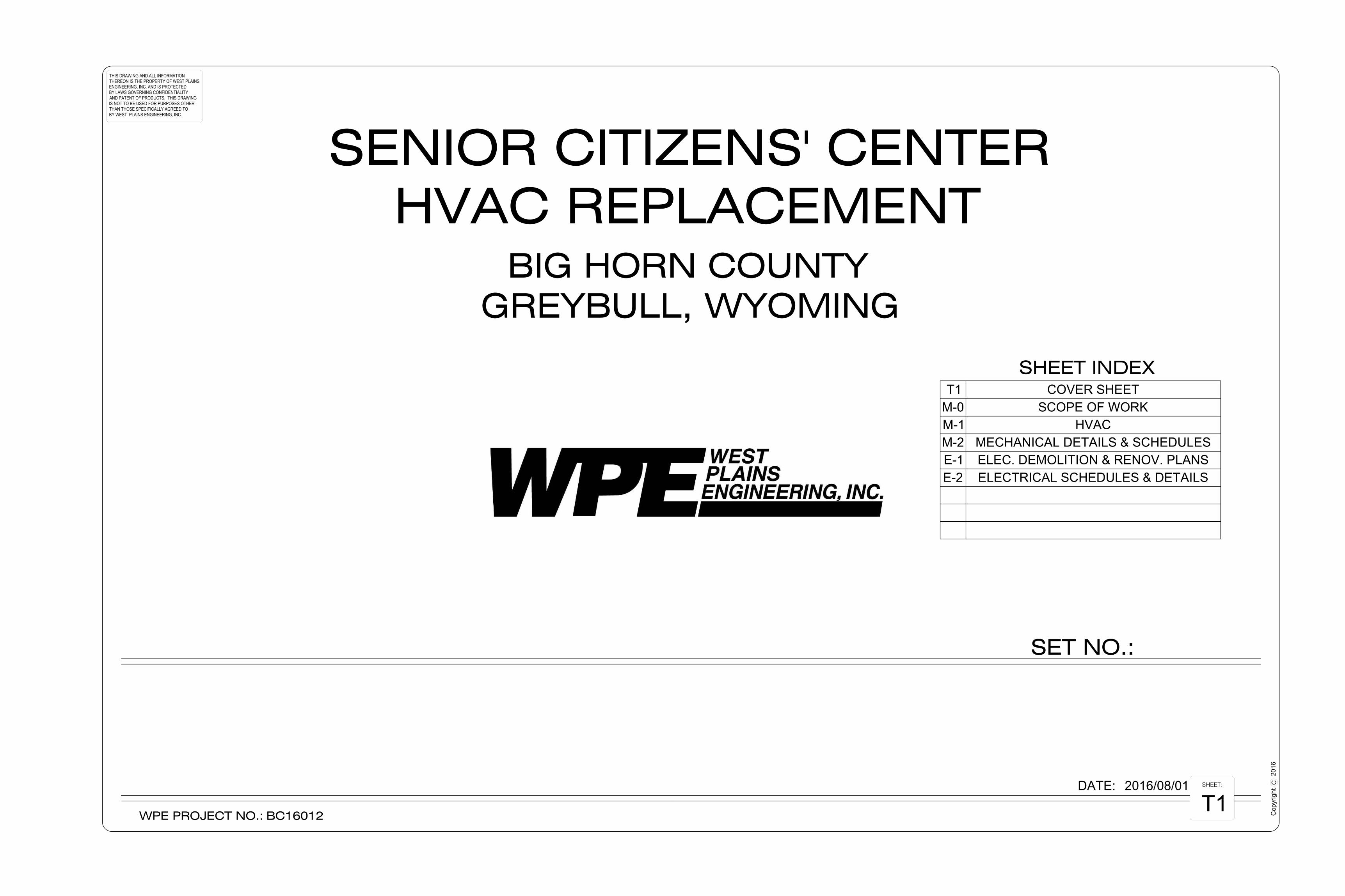
WPE PROJECT NO.: SHEET INDEX THIS DRAWING AND ALL INFORMATION THEREON IS THE PROPERTY OF WEST PLAINS ENGINEERING, INC. AND IS PROTECTED BY LAWS GOVERNING CONFIDENTIALITY AND PATENT OF PRODUCTS. THIS DRAWING IS NOT TO BE USED FOR PURPOSES OTHER THAN THOSE SPECIFICALLY AGREED TO BY WEST PLAINS ENGINEERING, INC. SHEET: SET NO.: C Copyright DATE: BC16012 SENIOR CITIZENS' CENTER HVAC REPLACEMENT BIG HORN COUNTY GREYBULL, WYOMING T1 2016 2016/08/01 M-0 SCOPE OF WORK M-1 HVAC M-2 MECHANICAL DETAILS & SCHEDULES T1 COVER SHEET E-1 ELEC. DEMOLITION & RENOV. PLANS E-2 ELECTRICAL SCHEDULES & DETAILS
Transcript of THIS DRAWING AND ALL INFORMATION THEREON … Horn County Senior... · hb. hose bib. flex duct (5'...
WPE PROJECT NO.:
SHEET INDEX
THIS DRAWING AND ALL INFORMATIONTHEREON IS THE PROPERTY OF WEST PLAINSENGINEERING, INC. AND IS PROTECTEDBY LAWS GOVERNING CONFIDENTIALITYAND PATENT OF PRODUCTS. THIS DRAWINGIS NOT TO BE USED FOR PURPOSES OTHERTHAN THOSE SPECIFICALLY AGREED TOBY WEST PLAINS ENGINEERING, INC.
SHEET:
SET NO.:
CC
opyr
ightDATE:
BC16012
SENIOR CITIZENS' CENTERHVAC REPLACEMENT
BIG HORN COUNTYGREYBULL, WYOMING
T1
2016
2016/08/01
M-0 SCOPE OF WORKM-1 HVACM-2 MECHANICAL DETAILS & SCHEDULES
T1 COVER SHEET
E-1 ELEC. DEMOLITION & RENOV. PLANSE-2 ELECTRICAL SCHEDULES & DETAILS

WE
ST
PL
AIN
SE
NG
INE
ER
ING
. IN
C.
WW
W.W
ESTPLAIN
SEN
GIN
EERIN
G.CO
M
RAPID
CITY, SD
▪ SIO
UX FALLS, SD
▪ CASPER, W
Y ▪ CED
AR RAPID
S, IA ▪ BISM
ARCK, N
D
THIS DRAWING AND ALLINFORMATION THEREON IS THE
PROPERTY OF WEST PLAINSENGINEERING, INC. AND IS
PROTECTED BY LAWSGOVERNING CONFIDENTIALITY
AND PATENT OF PRODUCTS.THIS DRAWING IS NOT TO BE
USED FOR PURPOSES OTHERTHAN THOSE SPECIFICALLY
AGREED TO BY WEST PLAINSENGINEERING, INC.
145 S. D
URBIN
, SU
ITE 205 ▪ CASPER, W
Y 82601
PH
ON
E: (307) 234-9484 ▪ FAX: (307) 234-5494
GR
EY
BU
LL, W
YO
MIN
G
8-1-16
BC16012
SIJM
LP
Copyright C
DATE:
APPROVED:
DRAWN:
DESIGNED:
# DATEDESCRIPTIONREVISIONS
SHEET:
PROJECT#:
SE
NIO
R C
ITIZ
EN
S' C
EN
TER
HV
AC
RE
PLA
CE
ME
NT
BIG
HO
RN
CO
UN
TY
SC
OP
E O
F P
RO
JEC
T
M-0 1/8" = 1'-0"1 SCOPE OF PROJECT
AutoCAD SHX Text
SKYLIGHT
AutoCAD SHX Text
LOUNGE
AutoCAD SHX Text
110
AutoCAD SHX Text
MEETING ROOM
AutoCAD SHX Text
126
AutoCAD SHX Text
STOR. 111
AutoCAD SHX Text
STOR. 112
AutoCAD SHX Text
STOR. 113
AutoCAD SHX Text
DRY STOR. 128
AutoCAD SHX Text
DISHWASH 130
AutoCAD SHX Text
TRASH 129
AutoCAD SHX Text
KITCHEN 127
AutoCAD SHX Text
FREEZER
AutoCAD SHX Text
GAME ROOM 125
AutoCAD SHX Text
STOR. 124
AutoCAD SHX Text
STOR. 123
AutoCAD SHX Text
CORR. 121
AutoCAD SHX Text
STOR. 119
AutoCAD SHX Text
MEN 114
AutoCAD SHX Text
WOMEN 116
AutoCAD SHX Text
HALL 105
AutoCAD SHX Text
VESTIBULE 101
AutoCAD SHX Text
RECEPTIONIST 102
AutoCAD SHX Text
QUILTING 122
AutoCAD SHX Text
CRAFTS 118
AutoCAD SHX Text
DIRECTOR 103
AutoCAD SHX Text
SECRETARY 104
AutoCAD SHX Text
NURSE 106
AutoCAD SHX Text
DIETICIAN 107
AutoCAD SHX Text
STORAGE 108
AutoCAD SHX Text
MECH. & JAN. 109
AutoCAD SHX Text
PUBLIC HEALTH
AutoCAD SHX Text
STORAGE
AutoCAD SHX Text
VESTIBULE
AutoCAD SHX Text
STORAGE
AutoCAD SHX Text
COOLER
AutoCAD SHX Text
VESTIBULE 100
AutoCAD SHX Text
COMMON ENTRY
AutoCAD SHX Text
AREA NOT IN CONTRACT (NO WORK IN THIS AREA)
AutoCAD SHX Text
1
AutoCAD SHX Text
2
AutoCAD SHX Text
3
AutoCAD SHX Text
1
AutoCAD SHX Text
4
AutoCAD SHX Text
1
AutoCAD SHX Text
HEAT PUMP WATER RETURN
AutoCAD SHX Text
HEAT PUMP WATER SUPPLY
AutoCAD SHX Text
GRILLE, REGISTER & DIFFUSER DESIGNATION
AutoCAD SHX Text
PRESSURE/TEMPERATURE TAP
AutoCAD SHX Text
CONNECT TO EXIST. SERVICE
AutoCAD SHX Text
HOT WATER HEATING SUPPLY
AutoCAD SHX Text
HOT WATER HEATING RETURN
AutoCAD SHX Text
POST INDICATOR VALVE
AutoCAD SHX Text
HB
AutoCAD SHX Text
HOSE BIB
AutoCAD SHX Text
FLEX DUCT (5' MAXIMUM)
AutoCAD SHX Text
OVERFLOW ROOF DRAIN
AutoCAD SHX Text
WALL CLEAN OUT
AutoCAD SHX Text
FLOOR SINK
AutoCAD SHX Text
ROOF DRAIN
AutoCAD SHX Text
RADIATION ELEMENT
AutoCAD SHX Text
C-COMBINATION FIRE SMOKE DAMPER
AutoCAD SHX Text
S-SMOKE DAMPER
AutoCAD SHX Text
R EQUAL W (MINIMUM)
AutoCAD SHX Text
OF AIR FLOW
AutoCAD SHX Text
F-FIRE DAMPER
AutoCAD SHX Text
FLEXIBLE DUCT CONNECTION
AutoCAD SHX Text
DUCT TURN WITH TURN VANES
AutoCAD SHX Text
STANDARD RADIUS ELBOW
AutoCAD SHX Text
DUCT RISE OR DROP IN DIRECTION
AutoCAD SHX Text
RETURN DUCT (UP & DOWN)
AutoCAD SHX Text
SUPPLY DUCT (UP & DOWN)
AutoCAD SHX Text
AREA DRAIN
AutoCAD SHX Text
FLOOR DRAIN
AutoCAD SHX Text
CLEAN OUT IN FLOOR
AutoCAD SHX Text
S
AutoCAD SHX Text
F
AutoCAD SHX Text
M
AutoCAD SHX Text
C
AutoCAD SHX Text
B
AutoCAD SHX Text
R
AutoCAD SHX Text
W
AutoCAD SHX Text
R OR D
AutoCAD SHX Text
FS
AutoCAD SHX Text
ORD
AutoCAD SHX Text
RD
AutoCAD SHX Text
AD
AutoCAD SHX Text
WCO
AutoCAD SHX Text
FD
AutoCAD SHX Text
CO
AutoCAD SHX Text
TYPE OF EQUIP
AutoCAD SHX Text
TYPE OF EQUIP
AutoCAD SHX Text
EQUIP. NO.
AutoCAD SHX Text
M-MOTORIZED DAMPER
AutoCAD SHX Text
B-BACKDRAFT DAMPER
AutoCAD SHX Text
EF
AutoCAD SHX Text
200
AutoCAD SHX Text
R-1
AutoCAD SHX Text
1
AutoCAD SHX Text
CFM
AutoCAD SHX Text
SUPPLY, RETURN, EXHAUST, & TRANSFER
AutoCAD SHX Text
EQUIPMENT DESIGNATION
AutoCAD SHX Text
PENDANT TYPE SPRINKLER HEAD
AutoCAD SHX Text
UPRIGHT SPRINKLER HEAD
AutoCAD SHX Text
RADIATION DESIGNATION
AutoCAD SHX Text
12/8
AutoCAD SHX Text
1/2 A
AutoCAD SHX Text
VENTILATION SYMBOLS
AutoCAD SHX Text
FIRE DEPT. HOSE VALVE
AutoCAD SHX Text
RECESSED SPRINKLER HEAD
AutoCAD SHX Text
CONCEALED SPRINKLER HEAD
AutoCAD SHX Text
RAD-1
AutoCAD SHX Text
5'-0"
AutoCAD SHX Text
ELEMENT
AutoCAD SHX Text
LENGTH
AutoCAD SHX Text
FINNED
AutoCAD SHX Text
TYPE
AutoCAD SHX Text
(NON-ADJUSTABLE)
AutoCAD SHX Text
(SEE SPECIFICATION)
AutoCAD SHX Text
BRANCH DUCT INTO SIDE OF MAIN DUCT
AutoCAD SHX Text
DUCT DIMENSION- WIDTH x DEPTH
AutoCAD SHX Text
DUCT INSULATION
AutoCAD SHX Text
DUCT TURN AND AIR SPLIT TYPE TAKEOFF
AutoCAD SHX Text
MANUAL VOLUME DAMPER
AutoCAD SHX Text
A
AutoCAD SHX Text
T
AutoCAD SHX Text
L
AutoCAD SHX Text
N
AutoCAD SHX Text
T
AutoCAD SHX Text
H
AutoCAD SHX Text
T
AutoCAD SHX Text
THERMOSTAT W/LOCKABLE COVER
AutoCAD SHX Text
NIGHT THERMOSTAT
AutoCAD SHX Text
HUMIDISTAT
AutoCAD SHX Text
FLOW ALARM
AutoCAD SHX Text
THERMOSTAT
AutoCAD SHX Text
OVERFLOW STORM PIPE
AutoCAD SHX Text
ABOVE FLOOR WASTE PIPE
AutoCAD SHX Text
WALL HYDRANT
AutoCAD SHX Text
FLEXIBLE PIPE CONNECTION
AutoCAD SHX Text
REDUCER OR INCREASER
AutoCAD SHX Text
PIPE ANCHOR
AutoCAD SHX Text
DIRECTION OF FLOW
AutoCAD SHX Text
PIPE PITCH DOWN
AutoCAD SHX Text
ELBOW DOWN
AutoCAD SHX Text
PIPE CONNECTION
AutoCAD SHX Text
FUEL OIL RETURN
AutoCAD SHX Text
FUEL OIL SUPPLY
AutoCAD SHX Text
LIQUEFIED PETROLEUM GAS
AutoCAD SHX Text
NATURAL GAS
AutoCAD SHX Text
COLD SOFT WATER PIPE
AutoCAD SHX Text
CIRCULATING HOT WATER PIPE
AutoCAD SHX Text
HOT WATER PIPE
AutoCAD SHX Text
COLD WATER PIPE
AutoCAD SHX Text
ACID RESISTANT VENT PIPE
AutoCAD SHX Text
ABOVE FLOOR ACID
AutoCAD SHX Text
VENT PIPE
AutoCAD SHX Text
UNDERFLOOR WASTE PIPE
AutoCAD SHX Text
WH
AutoCAD SHX Text
UNION
AutoCAD SHX Text
ELBOW UP
AutoCAD SHX Text
TEE DOWN
AutoCAD SHX Text
LP
AutoCAD SHX Text
FOR
AutoCAD SHX Text
FOS
AutoCAD SHX Text
G
AutoCAD SHX Text
S
AutoCAD SHX Text
OST
AutoCAD SHX Text
AV
AutoCAD SHX Text
AW
AutoCAD SHX Text
CLINICAL AND LAB AIR PIPE
AutoCAD SHX Text
NITROUS OXIDE PIPE
AutoCAD SHX Text
CLINICAL AND LAB VACUUM
AutoCAD SHX Text
GAS EVACUATION PIPE
AutoCAD SHX Text
CONDENSER WATER SUPPLY PIPE
AutoCAD SHX Text
CONDENSER WATER RETURN PIPE
AutoCAD SHX Text
CHILLED WATER SUPPLY PIPE
AutoCAD SHX Text
CHILLED WATER RETURN PIPE
AutoCAD SHX Text
REFRIGERANT LIQUID PIPE
AutoCAD SHX Text
REFRIGERANT SUCTION PIPE
AutoCAD SHX Text
FLOW MEASURING DEVICE
AutoCAD SHX Text
EXPANSION JOINT, PIPE GUIDE
AutoCAD SHX Text
BALANCING VALVE
AutoCAD SHX Text
3-WAY CONTROL VALVE
AutoCAD SHX Text
PRESSURE REDUCING VALVE
AutoCAD SHX Text
PRESSURE RELIEF VALVE
AutoCAD SHX Text
DOWN SPOUT
AutoCAD SHX Text
CHECK VALVE
AutoCAD SHX Text
STAND PIPE
AutoCAD SHX Text
DS
AutoCAD SHX Text
SP
AutoCAD SHX Text
CAPPED OUTLET
AutoCAD SHX Text
SHUT OFF VALVE
AutoCAD SHX Text
CONTROL VALVE
AutoCAD SHX Text
CWR
AutoCAD SHX Text
RS
AutoCAD SHX Text
RL
AutoCAD SHX Text
CWS
AutoCAD SHX Text
CR
AutoCAD SHX Text
CS
AutoCAD SHX Text
NITROGEN PIPE
AutoCAD SHX Text
OXYGEN PIPE
AutoCAD SHX Text
GE
AutoCAD SHX Text
VAC
AutoCAD SHX Text
NO
AutoCAD SHX Text
O
AutoCAD SHX Text
N
AutoCAD SHX Text
A
AutoCAD SHX Text
S
AutoCAD SHX Text
F
AutoCAD SHX Text
STRAINER VALVE
AutoCAD SHX Text
FLOW CONTROL VALVE
AutoCAD SHX Text
BACK FLOW PREVENTER
AutoCAD SHX Text
CURB STOP
AutoCAD SHX Text
PRESSURE GAUGE
AutoCAD SHX Text
THERMOMETER
AutoCAD SHX Text
STRAINER
AutoCAD SHX Text
STEAM TRAP
AutoCAD SHX Text
AIR VENT
AutoCAD SHX Text
D
AutoCAD SHX Text
HPWR
AutoCAD SHX Text
HPWS
AutoCAD SHX Text
LS
AutoCAD SHX Text
PC
AutoCAD SHX Text
F
AutoCAD SHX Text
HWR
AutoCAD SHX Text
HWS
AutoCAD SHX Text
HG
AutoCAD SHX Text
LPR
AutoCAD SHX Text
LPS
AutoCAD SHX Text
MPR
AutoCAD SHX Text
EQUIPMENT DRAIN
AutoCAD SHX Text
PUMPED CONDENSATE PIPE
AutoCAD SHX Text
FIRE SPRINKLER PIPE
AutoCAD SHX Text
LAWN SPRINKLER PIPE
AutoCAD SHX Text
MEDIUM PRESSURE RETURN
AutoCAD SHX Text
LOW PRESSURE STEAM
AutoCAD SHX Text
LOW PRESSURE RETURN
AutoCAD SHX Text
HOT GAS
AutoCAD SHX Text
COMPRESSED AIR PIPE
AutoCAD SHX Text
FUEL OIL GAUGE
AutoCAD SHX Text
FUEL OIL VENT
AutoCAD SHX Text
CA
AutoCAD SHX Text
FOG
AutoCAD SHX Text
FOV
AutoCAD SHX Text
MPS
AutoCAD SHX Text
HPR
AutoCAD SHX Text
HPS
AutoCAD SHX Text
HIGH PRESSURE STEAM
AutoCAD SHX Text
HIGH PRESSURE RETURN
AutoCAD SHX Text
MEDIUM PRESSURE STEAM
AutoCAD SHX Text
MECHANICAL SYMBOLS
AutoCAD SHX Text
RESISTANT WASTE PIPE
AutoCAD SHX Text
UNDERFLOOR ACID WASTE PIPE
AutoCAD SHX Text
HOT WATER PIPE
AutoCAD SHX Text
HOT WATER PIPE
AutoCAD SHX Text
COLD WATER PIPE
AutoCAD SHX Text
UNDERGOUND CIRCULATING
AutoCAD SHX Text
UNDERGROUND
AutoCAD SHX Text
UNDERGROUND
AutoCAD SHX Text
ABOVE FLOOR
AutoCAD SHX Text
ST
AutoCAD SHX Text
STORM PIPE
AutoCAD SHX Text
UNDERFLOOR STORM PIPE
AutoCAD SHX Text
ABOVE FLOOR
AutoCAD SHX Text
STORM PIPE
AutoCAD SHX Text
UNDERFLOOR OVERFLOW
AutoCAD SHX Text
OST
AutoCAD SHX Text
ST
AutoCAD SHX Text
AW
AutoCAD SHX Text
EXHAUST DUCT (UP & DOWN)
AutoCAD SHX Text
SPIRAL DUCTWORK
AutoCAD SHX Text
GROUND LOOP WATER RETURN
AutoCAD SHX Text
GROUND LOOP WATER SUPPLY
AutoCAD SHX Text
GLWR
AutoCAD SHX Text
GLWS
AutoCAD SHX Text
CLEAN OUT ABOVE FLOOR
AutoCAD SHX Text
CO
AutoCAD SHX Text
DOMESTIC WATER TEMPERING VALVE
AutoCAD SHX Text
FLOW SWITCH
AutoCAD SHX Text
FS
AutoCAD SHX Text
PRESSURE SENSOR DIFFERENTIAL
AutoCAD SHX Text
P
AutoCAD SHX Text
STATIC PRESSURE SENSOR
AutoCAD SHX Text
P
AutoCAD SHX Text
DEMOLITION HATCHING
AutoCAD SHX Text
O
AutoCAD SHX Text
OXYGEN OUTLET
AutoCAD SHX Text
NO
AutoCAD SHX Text
NITROUS OXIDE OUTLET
AutoCAD SHX Text
V
AutoCAD SHX Text
CLINICAL AND LAB
AutoCAD SHX Text
GE
AutoCAD SHX Text
GAS EVACUATION OUTLET
AutoCAD SHX Text
N
AutoCAD SHX Text
NITROGEN OUTLET
AutoCAD SHX Text
A
AutoCAD SHX Text
CLINICAL AIR OUTLET
AutoCAD SHX Text
CA
AutoCAD SHX Text
COMPRESSED AIR OUTLET
AutoCAD SHX Text
PD
AutoCAD SHX Text
PUMP DISCHARGE
AutoCAD SHX Text
PD
AutoCAD SHX Text
PUMP DISCHARGE
AutoCAD SHX Text
VACUUM OUTLET
AutoCAD SHX Text
LOW PRESURE DUCTWORK
AutoCAD SHX Text
MEDIUM PRESSURE DUCTWORK
AutoCAD SHX Text
MAX 2" W.G. PRESSURE
AutoCAD SHX Text
2"-6" W.G. PRESSURE
AutoCAD SHX Text
e
AutoCAD SHX Text
11282
AutoCAD SHX Text
Date
AutoCAD SHX Text
M
AutoCAD SHX Text
Y
AutoCAD SHX Text
W
AutoCAD SHX Text
O
AutoCAD SHX Text
i
AutoCAD SHX Text
f
AutoCAD SHX Text
o
AutoCAD SHX Text
r
AutoCAD SHX Text
P
AutoCAD SHX Text
s
AutoCAD SHX Text
e
AutoCAD SHX Text
s
AutoCAD SHX Text
n
AutoCAD SHX Text
o
AutoCAD SHX Text
n
AutoCAD SHX Text
i
AutoCAD SHX Text
n
AutoCAD SHX Text
E
AutoCAD SHX Text
l
AutoCAD SHX Text
a
AutoCAD SHX Text
g
AutoCAD SHX Text
I
AutoCAD SHX Text
N
AutoCAD SHX Text
G
AutoCAD SHX Text
h
AutoCAD SHX Text
c
AutoCAD SHX Text
a
AutoCAD SHX Text
a
AutoCAD SHX Text
c
AutoCAD SHX Text
i
AutoCAD SHX Text
n
AutoCAD SHX Text
l
AutoCAD SHX Text
)
AutoCAD SHX Text
e
AutoCAD SHX Text
(
AutoCAD SHX Text
r
AutoCAD SHX Text
e
AutoCAD SHX Text
M
AutoCAD SHX Text
N
AutoCAD SHX Text
PROJECT GENERAL NOTES: A.THE INTENT OF THIS PROJECT IS TO REPLACE THE EXISTING THE INTENT OF THIS PROJECT IS TO REPLACE THE EXISTING HVAC SYSTEM WITH A NEW HVAC SYSTEM. THE EXISTING SYSTEM CONSISTS OF AN AIR HANDLING UNIT THAT IS ZONED WITH HYDRONIC REHEAT COILS. HYDRONIC REHEAT COILS ARE SERVED BY A GAS FIRED HOT WATER BOILER. B.COORDINATE ALL DEMOLITION AND NEW WORK WITH THE COORDINATE ALL DEMOLITION AND NEW WORK WITH THE OWNER TO MINIMIZE INTERRUPTION OF USE OF THE BUILDING AS MUCH AS POSSIBLE. THE OWNER INTENDS TO OCCUPY ONLY THE ADMINISTRATION PORTION OF THE BUILDING THROUGH THE DURATION OF CONSTRUCTION. THE CONTRACTOR SHALL COORDINATE WITH THE OWNER ON SCHEDULING OF ALL DEMOLITION AND NEW WORK. C.THE CONTRACTOR SHALL PROVIDE MEANS FOR TEMPORARY THE CONTRACTOR SHALL PROVIDE MEANS FOR TEMPORARY HEAT OF THE BUILDING AS REQUIRED TO PREVENT FREEZING OF ALL WATER LINES. D.THE EXISTING KITCHEN CONSISTS OF A KITCHEN HOOD, THE EXISTING KITCHEN CONSISTS OF A KITCHEN HOOD, KITCHEN EXHAUST FAN, MAKE-UP AIR UNIT, DISHWASHER HOOD, AND DISHWASHER EXHAUST FAN. ALL KITCHEN ITEMS ASSOCIATED WITH EXHAUST AND MAKE-UP AIR SHALL REMAIN. ONLY THE HVAC SYSTEM SERVING THE KITCHEN WILL BE MODIFIED. E.THE OWNER HAS RETAINED A CONTRACTOR TO REMOVE ALL THE OWNER HAS RETAINED A CONTRACTOR TO REMOVE ALL EXISTING LAY-IN CEILINGS, TO PROVIDE A NEW LAY-IN GRID CEILING AND TO PROVIDE NEW LIGHTING FIXTURES. THE SUCCESSFUL CONTRACTOR FOR THIS PROJECT SHALL COORDINATE SCHEDULING WITH THE OWNER AND THE OWNER'S CONTRACTOR. THE SUCCESSFUL CONTRACTOR SHALL COORDINATE WITH THE OWNER AND THE OWNER'S CONTRACTOR FOR THE FINAL PLACEMENT OF ALL DIFFUSERS TO COORDINATE WITH THE NEW LIGHTING. F.CONTRACTOR SHALL TAKE ALL PRECAUTIONS AS CONTRACTOR SHALL TAKE ALL PRECAUTIONS AS NECESSARY TO PROTECT THE EXISTING BUILDING AND ITS COMPONENTS FROM DAMAGE DURING THE CONSTRUCTION PROCESS. THE CONTRACTOR SHALL MAKE PROVISIONS TO COMPLETELY DRAIN THE EXISTING BOILER SYSTEM PRIOR TO REMOVAL AND TO PROTECT ALL CARPET FROM DAMAGE DURING THE REMOVAL OF ALL HYDRONIC PIPING THROUGHOUGHT THE BUILDING. G.THE CONTRACTOR SHALL COMPLETELY REMOVE ALL ITEMS THE CONTRACTOR SHALL COMPLETELY REMOVE ALL ITEMS AS INDICATED IN THE DRAWINGS. THE OWNER SHALL HAVE FIRST RIGHT OF SALVAGE FOR ALL REMOVED ITEMS. ALL UNWANTED ITEMS SHALL BE DISPOSED OF LEGALLY AND RESPONSIBLY. ALL RECYCLABLE MATERIAL SHALL BE RECYCLED. H.THE EXISTING SYSTEM UTILIZES A BELOW SLAB RETURN AIR THE EXISTING SYSTEM UTILIZES A BELOW SLAB RETURN AIR DUCT. THE EXISTING BELOW SLAB RETURN AIR DUCT WILL NOT BE RE-USED IN THE NEW HVAC SYSTEM. THE EXISTING BELOW SLAB RETURN AIR DUCT SHALL BE ABANDONED IN PLACE. THE EXISTING RETURN OPENINGS AT EACH OF THE ROOMS SHALL BE CAPPED WITH AN INSULATED SHEET METAL PANEL. PAINT THE SHEET METAL PANEL BLACK AND RE-INSTALL THE EXISTING RETURN AIR GRILLES OVER THE PAINTED SHEET METAL PANELS. I.PROVIDE ALL MATERIALS AND EQUIPMENT AND PERFORM PROVIDE ALL MATERIALS AND EQUIPMENT AND PERFORM ALL LABOR REQUIRED TO INSTALL COMPLETE AND OPERABLE MECHANICAL AND ELECTRICAL SYSTEMS AS INDICATED ON THE DRAWINGS, AS SPECIFIED, AND AS REQUIRED BY CODE. J.CONTRACT DOCUMENTS DRAWINGS FOR HVAC WORK ARE CONTRACT DOCUMENTS DRAWINGS FOR HVAC WORK ARE DIAGRAMMATIC AND ARE INTENDED TO CONVEY SCOPE AND GENERAL ARRANGEMENT ONLY. CONTRACTOR SHALL USE ACTUAL FIELD MEASUREMENTS FOR LAYOUT. K.INSTALL ALL MECHANICAL EQUIPMENT AND APPURTENANCES INSTALL ALL MECHANICAL EQUIPMENT AND APPURTENANCES IN ACCORDANCE WITH MANUFACTURER'S RECOMMENDATIONS, CONTRACT DOCUMENTS, AND APPLICABLE CODES AND REGULATIONS. L.ALL TEMPERATURE CONTROL WIRING SHALL BE BY THE ALL TEMPERATURE CONTROL WIRING SHALL BE BY THE MECHANICAL CONTRACTOR. M.COORDINATE ALL EQUIPMENT CONNECTIONS WITH COORDINATE ALL EQUIPMENT CONNECTIONS WITH MANUFACTURER'S CERTIFIED DRAWINGS. COORDINATE AND PROVIDE ALL DUCT TRANSITIONS REQUIRED FOR FINAL EQUIPMENT CONNECTIONS. FIELD VERIFY AND COORDINATE ALL DUCT DIMENSIONS PRIOR TO FABRICATION. PROJECT SPECIFIC NOTES: 1.PROVIDE ALL NEW HVAC WITHIN THIS BOUNDARY. THE PROVIDE ALL NEW HVAC WITHIN THIS BOUNDARY. THE OWNER HAS RETAINED A CONTRACTOR TO REMOVE AND REPLACE ALL LAY-IN CEILING AND LIGHTS. COORDINATE WORK WITH THE OWNER AND OWNER'S CONTRACTOR. 2.ALL CEILINGS SHALL REMAIN WITHIN THIS BOUNDARY. ALL CEILINGS SHALL REMAIN WITHIN THIS BOUNDARY. EXISTING HVACDUCTWORK AND DIFFUSERS SHALL REMAIN AND BE RECONNECTED TO NEW SYSTEM. 3.ALL CEILINGS SHALL REMAIN WITHIN THIS BOUNDARY. THE ALL CEILINGS SHALL REMAIN WITHIN THIS BOUNDARY. THE EXISTING KITCHEN CONSISTS OF A KITCHEN HOOD, KITCHEN EXHAUST FAN, MAKE-UP AIR UNIT, DISHWASHER HOOD, AND DISHWASHER EXHAUST FAN. ALL KITCHEN ITEMS ASSOCIATED WITH EXHAUST AND MAKE-UP AIR SHALL REMAIN. ONLY THE HVAC SYSTEM SERVING THE KITCHEN WILL BE MODIFIED. CONTRACTOR SHALL REMOVE AND REPLACE CEILING TILES AS REQUIRED TO FACILITATE INSTALLATION OF NEW DUCTWORK. ANY CEILING TILES DAMAGED DURING CONSTRUCTION SHALL BE REPLACED. 4.WITHIN THIS BOUNDARY ALL CEILINGS AND HVAC WITHIN THIS BOUNDARY ALL CEILINGS AND HVAC COMPONENTS SHALL REMAIN.
WE
ST
PL
AIN
SE
NG
INE
ER
ING
. IN
C.
WW
W.W
ESTPLAIN
SEN
GIN
EERIN
G.CO
M
RAPID
CITY, SD
▪ SIO
UX FALLS, SD
▪ CASPER, W
Y ▪ CED
AR RAPID
S, IA ▪ BISM
ARCK, N
D
THIS DRAWING AND ALLINFORMATION THEREON IS THE
PROPERTY OF WEST PLAINSENGINEERING, INC. AND IS
PROTECTED BY LAWSGOVERNING CONFIDENTIALITY
AND PATENT OF PRODUCTS.THIS DRAWING IS NOT TO BE
USED FOR PURPOSES OTHERTHAN THOSE SPECIFICALLY
AGREED TO BY WEST PLAINSENGINEERING, INC.
145 S. D
URBIN
, SU
ITE 205 ▪ CASPER, W
Y 82601
PH
ON
E: (307) 234-9484 ▪ FAX: (307) 234-5494
GR
EY
BU
LL, W
YO
MIN
G
8-1-16
BC16012
SIJM
LP
Copyright C
DATE:
APPROVED:
DRAWN:
DESIGNED:
# DATEDESCRIPTIONREVISIONS
SHEET:
PROJECT#:
SE
NIO
R C
ITIZ
EN
S' C
EN
TER
HV
AC
RE
PLA
CE
ME
NT
BIG
HO
RN
CO
UN
TY
HV
AC
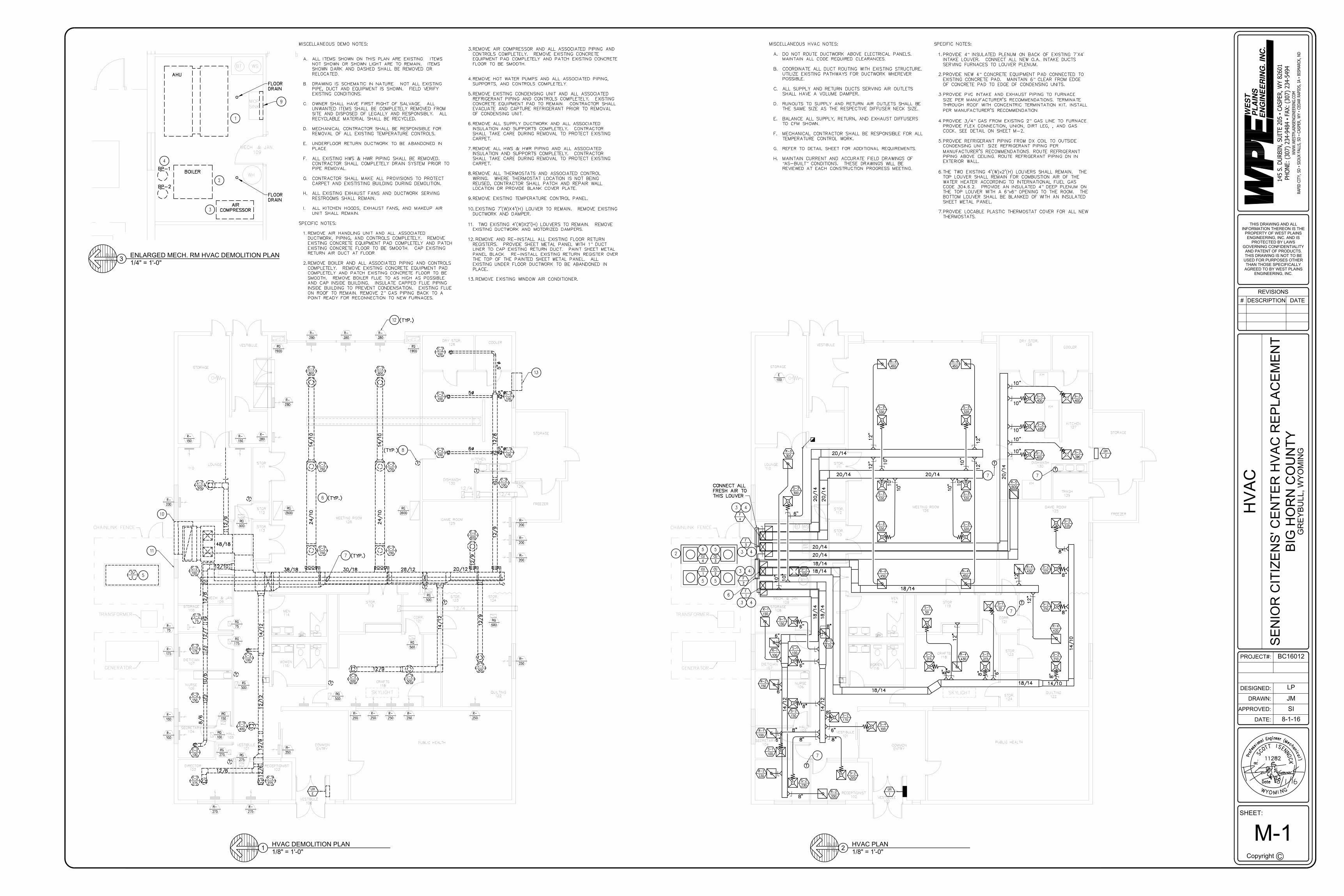
M-1 1/8" = 1'-0"1 HVAC DEMOLITION PLAN
1/8" = 1'-0"2 HVAC PLAN
1/4" = 1'-0"3 ENLARGED MECH. RM HVAC DEMOLITION PLAN
”
”
“ ”
”
””
” ”
”” ”
AutoCAD SHX Text
SKYLIGHT
AutoCAD SHX Text
LOUNGE
AutoCAD SHX Text
110
AutoCAD SHX Text
MEETING ROOM
AutoCAD SHX Text
126
AutoCAD SHX Text
STOR. 111
AutoCAD SHX Text
STOR. 112
AutoCAD SHX Text
STOR. 113
AutoCAD SHX Text
DRY STOR. 128
AutoCAD SHX Text
DISHWASH 130
AutoCAD SHX Text
TRASH 129
AutoCAD SHX Text
KITCHEN 127
AutoCAD SHX Text
FREEZER
AutoCAD SHX Text
GAME ROOM 125
AutoCAD SHX Text
STOR. 124
AutoCAD SHX Text
STOR. 123
AutoCAD SHX Text
CORR. 121
AutoCAD SHX Text
STOR. 119
AutoCAD SHX Text
MEN 114
AutoCAD SHX Text
WOMEN 116
AutoCAD SHX Text
HALL 105
AutoCAD SHX Text
VESTIBULE 101
AutoCAD SHX Text
RECEPTIONIST 102
AutoCAD SHX Text
QUILTING 122
AutoCAD SHX Text
CRAFTS 118
AutoCAD SHX Text
SECRETARY 104
AutoCAD SHX Text
NURSE 106
AutoCAD SHX Text
DIETICIAN 107
AutoCAD SHX Text
STORAGE 108
AutoCAD SHX Text
MECH. & JAN. 109
AutoCAD SHX Text
18/14
AutoCAD SHX Text
14/12
AutoCAD SHX Text
18/14
AutoCAD SHX Text
18/14
AutoCAD SHX Text
20/14
AutoCAD SHX Text
20/14
AutoCAD SHX Text
20/14
AutoCAD SHX Text
20/14
AutoCAD SHX Text
20/14
AutoCAD SHX Text
20/14
AutoCAD SHX Text
20/14
AutoCAD SHX Text
20/14
AutoCAD SHX Text
18/14
AutoCAD SHX Text
18/14
AutoCAD SHX Text
18/14
AutoCAD SHX Text
14/10
AutoCAD SHX Text
14/10
AutoCAD SHX Text
18/14
AutoCAD SHX Text
14/12
AutoCAD SHX Text
R-2
AutoCAD SHX Text
200
AutoCAD SHX Text
8"
AutoCAD SHX Text
8"
AutoCAD SHX Text
8"
AutoCAD SHX Text
8"
AutoCAD SHX Text
8"
AutoCAD SHX Text
8"
AutoCAD SHX Text
6"
AutoCAD SHX Text
6"
AutoCAD SHX Text
12"
AutoCAD SHX Text
12"
AutoCAD SHX Text
12"
AutoCAD SHX Text
12"
AutoCAD SHX Text
10"
AutoCAD SHX Text
10"
AutoCAD SHX Text
10"
AutoCAD SHX Text
10"
AutoCAD SHX Text
6"
AutoCAD SHX Text
8"
AutoCAD SHX Text
8"
AutoCAD SHX Text
6"
AutoCAD SHX Text
8"
AutoCAD SHX Text
10"
AutoCAD SHX Text
10"
AutoCAD SHX Text
10"
AutoCAD SHX Text
8"
AutoCAD SHX Text
8"
AutoCAD SHX Text
12"
AutoCAD SHX Text
12"
AutoCAD SHX Text
12"
AutoCAD SHX Text
S-2
AutoCAD SHX Text
200
AutoCAD SHX Text
S-2
AutoCAD SHX Text
230
AutoCAD SHX Text
S-1
AutoCAD SHX Text
100
AutoCAD SHX Text
S-1
AutoCAD SHX Text
50
AutoCAD SHX Text
S-2
AutoCAD SHX Text
215
AutoCAD SHX Text
S-2
AutoCAD SHX Text
215
AutoCAD SHX Text
S-2
AutoCAD SHX Text
210
AutoCAD SHX Text
S-1
AutoCAD SHX Text
50
AutoCAD SHX Text
S-2
AutoCAD SHX Text
225
AutoCAD SHX Text
S-2
AutoCAD SHX Text
225
AutoCAD SHX Text
S-3
AutoCAD SHX Text
400
AutoCAD SHX Text
S-3
AutoCAD SHX Text
400
AutoCAD SHX Text
S-3
AutoCAD SHX Text
400
AutoCAD SHX Text
R-5
AutoCAD SHX Text
1600
AutoCAD SHX Text
R-4
AutoCAD SHX Text
450
AutoCAD SHX Text
R-4
AutoCAD SHX Text
450
AutoCAD SHX Text
R-4
AutoCAD SHX Text
450
AutoCAD SHX Text
S-3
AutoCAD SHX Text
330
AutoCAD SHX Text
S-3
AutoCAD SHX Text
330
AutoCAD SHX Text
S-3
AutoCAD SHX Text
330
AutoCAD SHX Text
S-3
AutoCAD SHX Text
330
AutoCAD SHX Text
S-3
AutoCAD SHX Text
330
AutoCAD SHX Text
S-3
AutoCAD SHX Text
330
AutoCAD SHX Text
R-4
AutoCAD SHX Text
450
AutoCAD SHX Text
R-4
AutoCAD SHX Text
450
AutoCAD SHX Text
S-2
AutoCAD SHX Text
170
AutoCAD SHX Text
R-3
AutoCAD SHX Text
300
AutoCAD SHX Text
S-3
AutoCAD SHX Text
300
AutoCAD SHX Text
R-1
AutoCAD SHX Text
100
AutoCAD SHX Text
S-2
AutoCAD SHX Text
150
AutoCAD SHX Text
R-2
AutoCAD SHX Text
150
AutoCAD SHX Text
S-1
AutoCAD SHX Text
100
AutoCAD SHX Text
R-1
AutoCAD SHX Text
100
AutoCAD SHX Text
S-1
AutoCAD SHX Text
150
AutoCAD SHX Text
R-4
AutoCAD SHX Text
420
AutoCAD SHX Text
R-4
AutoCAD SHX Text
430
AutoCAD SHX Text
8"
AutoCAD SHX Text
6"
AutoCAD SHX Text
R-2
AutoCAD SHX Text
170
AutoCAD SHX Text
10"
AutoCAD SHX Text
10"
AutoCAD SHX Text
PUBLIC HEALTH
AutoCAD SHX Text
STORAGE
AutoCAD SHX Text
VESTIBULE
AutoCAD SHX Text
STORAGE
AutoCAD SHX Text
COOLER
AutoCAD SHX Text
F
AutoCAD SHX Text
4
AutoCAD SHX Text
F
AutoCAD SHX Text
3
AutoCAD SHX Text
F
AutoCAD SHX Text
2
AutoCAD SHX Text
F
AutoCAD SHX Text
1
AutoCAD SHX Text
6"
AutoCAD SHX Text
6"
AutoCAD SHX Text
6"
AutoCAD SHX Text
S-4
AutoCAD SHX Text
100
AutoCAD SHX Text
UH
AutoCAD SHX Text
1
AutoCAD SHX Text
8"
AutoCAD SHX Text
S-2
AutoCAD SHX Text
210
AutoCAD SHX Text
UH
AutoCAD SHX Text
2
AutoCAD SHX Text
KH
AutoCAD SHX Text
KH
AutoCAD SHX Text
KH
AutoCAD SHX Text
S-3
AutoCAD SHX Text
400
AutoCAD SHX Text
S-3
AutoCAD SHX Text
390
AutoCAD SHX Text
10"
AutoCAD SHX Text
10"
AutoCAD SHX Text
E
AutoCAD SHX Text
100
AutoCAD SHX Text
10"
AutoCAD SHX Text
10"
AutoCAD SHX Text
WH
AutoCAD SHX Text
BT
AutoCAD SHX Text
WS
AutoCAD SHX Text
MOP SINK
AutoCAD SHX Text
CHAINLINK FENCE
AutoCAD SHX Text
TRANSFORMER
AutoCAD SHX Text
GENERATOR
AutoCAD SHX Text
CU
AutoCAD SHX Text
1
AutoCAD SHX Text
CU
AutoCAD SHX Text
2
AutoCAD SHX Text
CU
AutoCAD SHX Text
4
AutoCAD SHX Text
CU
AutoCAD SHX Text
3
AutoCAD SHX Text
VESTIBULE 100
AutoCAD SHX Text
COMMON ENTRY
AutoCAD SHX Text
T
AutoCAD SHX Text
R-2
AutoCAD SHX Text
230
AutoCAD SHX Text
R-1
AutoCAD SHX Text
150
AutoCAD SHX Text
T
AutoCAD SHX Text
4
AutoCAD SHX Text
3
AutoCAD SHX Text
5
AutoCAD SHX Text
5
AutoCAD SHX Text
4
AutoCAD SHX Text
3
AutoCAD SHX Text
4
AutoCAD SHX Text
3
AutoCAD SHX Text
4
AutoCAD SHX Text
3
AutoCAD SHX Text
6"
AutoCAD SHX Text
T
AutoCAD SHX Text
5
AutoCAD SHX Text
5
AutoCAD SHX Text
CONNECT ALL FRESH AIR TO THIS LOUVER
AutoCAD SHX Text
2
AutoCAD SHX Text
6
AutoCAD SHX Text
S-2
AutoCAD SHX Text
200
AutoCAD SHX Text
7
AutoCAD SHX Text
7
AutoCAD SHX Text
T
AutoCAD SHX Text
7
AutoCAD SHX Text
7
AutoCAD SHX Text
SKYLIGHT
AutoCAD SHX Text
12/4
AutoCAD SHX Text
38/18
AutoCAD SHX Text
30/18
AutoCAD SHX Text
28/12
AutoCAD SHX Text
20/12
AutoCAD SHX Text
12/9
AutoCAD SHX Text
24/10
AutoCAD SHX Text
24/10
AutoCAD SHX Text
14/10
AutoCAD SHX Text
14/10
AutoCAD SHX Text
48/18
AutoCAD SHX Text
12/9
AutoCAD SHX Text
14/12
AutoCAD SHX Text
12/9
AutoCAD SHX Text
C-2
AutoCAD SHX Text
500
AutoCAD SHX Text
C-2
AutoCAD SHX Text
500
AutoCAD SHX Text
C-2
AutoCAD SHX Text
500
AutoCAD SHX Text
RG
AutoCAD SHX Text
500
AutoCAD SHX Text
RG
AutoCAD SHX Text
500
AutoCAD SHX Text
RG
AutoCAD SHX Text
500
AutoCAD SHX Text
R-
AutoCAD SHX Text
250
AutoCAD SHX Text
R-
AutoCAD SHX Text
250
AutoCAD SHX Text
R-
AutoCAD SHX Text
250
AutoCAD SHX Text
R-
AutoCAD SHX Text
250
AutoCAD SHX Text
R-
AutoCAD SHX Text
250
AutoCAD SHX Text
R-
AutoCAD SHX Text
250
AutoCAD SHX Text
RG
AutoCAD SHX Text
500
AutoCAD SHX Text
R-
AutoCAD SHX Text
250
AutoCAD SHX Text
R-
AutoCAD SHX Text
275
AutoCAD SHX Text
R-
AutoCAD SHX Text
275
AutoCAD SHX Text
R-
AutoCAD SHX Text
100
AutoCAD SHX Text
R-
AutoCAD SHX Text
150
AutoCAD SHX Text
R-
AutoCAD SHX Text
175
AutoCAD SHX Text
R-
AutoCAD SHX Text
75
AutoCAD SHX Text
R-
AutoCAD SHX Text
200
AutoCAD SHX Text
R-
AutoCAD SHX Text
150
AutoCAD SHX Text
R-
AutoCAD SHX Text
150
AutoCAD SHX Text
R-
AutoCAD SHX Text
280
AutoCAD SHX Text
R-
AutoCAD SHX Text
280
AutoCAD SHX Text
R-
AutoCAD SHX Text
280
AutoCAD SHX Text
R-
AutoCAD SHX Text
280
AutoCAD SHX Text
R-
AutoCAD SHX Text
280
AutoCAD SHX Text
RG
AutoCAD SHX Text
1900
AutoCAD SHX Text
RG
AutoCAD SHX Text
1900
AutoCAD SHX Text
12/4
AutoCAD SHX Text
12/4
AutoCAD SHX Text
R-
AutoCAD SHX Text
200
AutoCAD SHX Text
R-
AutoCAD SHX Text
200
AutoCAD SHX Text
R-
AutoCAD SHX Text
200
AutoCAD SHX Text
C-2
AutoCAD SHX Text
600
AutoCAD SHX Text
RG
AutoCAD SHX Text
2600
AutoCAD SHX Text
C-2
AutoCAD SHX Text
800
AutoCAD SHX Text
C-2
AutoCAD SHX Text
800
AutoCAD SHX Text
C-2
AutoCAD SHX Text
750
AutoCAD SHX Text
C-2
AutoCAD SHX Text
750
AutoCAD SHX Text
C-2
AutoCAD SHX Text
750
AutoCAD SHX Text
C-2
AutoCAD SHX Text
750
AutoCAD SHX Text
LOUNGE
AutoCAD SHX Text
110
AutoCAD SHX Text
12/9
AutoCAD SHX Text
C-2
AutoCAD SHX Text
500
AutoCAD SHX Text
RG
AutoCAD SHX Text
500
AutoCAD SHX Text
RG
AutoCAD SHX Text
2600
AutoCAD SHX Text
14/12
AutoCAD SHX Text
RG
AutoCAD SHX Text
75
AutoCAD SHX Text
RG
AutoCAD SHX Text
175
AutoCAD SHX Text
12/9
AutoCAD SHX Text
12/12
AutoCAD SHX Text
C-2
AutoCAD SHX Text
400
AutoCAD SHX Text
C-2
AutoCAD SHX Text
100
AutoCAD SHX Text
RG
AutoCAD SHX Text
500
AutoCAD SHX Text
RG
AutoCAD SHX Text
150
AutoCAD SHX Text
RG
AutoCAD SHX Text
100
AutoCAD SHX Text
RG
AutoCAD SHX Text
275
AutoCAD SHX Text
RG
AutoCAD SHX Text
275
AutoCAD SHX Text
12/6
AutoCAD SHX Text
12/6
AutoCAD SHX Text
C-2
AutoCAD SHX Text
275
AutoCAD SHX Text
C-2
AutoCAD SHX Text
275
AutoCAD SHX Text
12/10
AutoCAD SHX Text
C-2
AutoCAD SHX Text
100
AutoCAD SHX Text
C-2
AutoCAD SHX Text
150
AutoCAD SHX Text
C-2
AutoCAD SHX Text
175
AutoCAD SHX Text
C-2
AutoCAD SHX Text
75
AutoCAD SHX Text
C-2
AutoCAD SHX Text
150
AutoCAD SHX Text
12/8
AutoCAD SHX Text
12/7
AutoCAD SHX Text
10/6
AutoCAD SHX Text
8/6
AutoCAD SHX Text
12/9
AutoCAD SHX Text
12/8
AutoCAD SHX Text
5"%%C
AutoCAD SHX Text
C-2
AutoCAD SHX Text
100
AutoCAD SHX Text
C-2
AutoCAD SHX Text
100
AutoCAD SHX Text
5%%C
AutoCAD SHX Text
C-2
AutoCAD SHX Text
100
AutoCAD SHX Text
5"%%C
AutoCAD SHX Text
C-2
AutoCAD SHX Text
100
AutoCAD SHX Text
C-2
AutoCAD SHX Text
100
AutoCAD SHX Text
C-2
AutoCAD SHX Text
100
AutoCAD SHX Text
6%%C
AutoCAD SHX Text
5"%%C
AutoCAD SHX Text
MEETING ROOM
AutoCAD SHX Text
126
AutoCAD SHX Text
STOR. 111
AutoCAD SHX Text
STOR. 112
AutoCAD SHX Text
STOR. 113
AutoCAD SHX Text
DRY STOR. 128
AutoCAD SHX Text
DISHWASH 130
AutoCAD SHX Text
TRASH 129
AutoCAD SHX Text
KITCHEN 127
AutoCAD SHX Text
FREEZER
AutoCAD SHX Text
GAME ROOM 125
AutoCAD SHX Text
STOR. 124
AutoCAD SHX Text
STOR. 123
AutoCAD SHX Text
CORR. 121
AutoCAD SHX Text
STOR. 119
AutoCAD SHX Text
MEN 114
AutoCAD SHX Text
WOMEN 116
AutoCAD SHX Text
HALL 105
AutoCAD SHX Text
VESTIBULE 101
AutoCAD SHX Text
RECEPTIONIST 102
AutoCAD SHX Text
QUILTING 122
AutoCAD SHX Text
CRAFTS 118
AutoCAD SHX Text
DIRECTOR 103
AutoCAD SHX Text
SECRETARY 104
AutoCAD SHX Text
NURSE 106
AutoCAD SHX Text
DIETICIAN 107
AutoCAD SHX Text
STORAGE 108
AutoCAD SHX Text
MECH. & JAN. 109
AutoCAD SHX Text
PUBLIC HEALTH
AutoCAD SHX Text
STORAGE
AutoCAD SHX Text
VESTIBULE
AutoCAD SHX Text
STORAGE
AutoCAD SHX Text
COOLER
AutoCAD SHX Text
T
AutoCAD SHX Text
T
AutoCAD SHX Text
T
AutoCAD SHX Text
T
AutoCAD SHX Text
T
AutoCAD SHX Text
T
AutoCAD SHX Text
T
AutoCAD SHX Text
CU
AutoCAD SHX Text
E
AutoCAD SHX Text
CHAINLINK FENCE
AutoCAD SHX Text
TRANSFORMER
AutoCAD SHX Text
GENERATOR
AutoCAD SHX Text
T
AutoCAD SHX Text
5
AutoCAD SHX Text
UH
AutoCAD SHX Text
E
AutoCAD SHX Text
VESTIBULE 100
AutoCAD SHX Text
COMMON ENTRY
AutoCAD SHX Text
12
AutoCAD SHX Text
(TYP.)
AutoCAD SHX Text
8
AutoCAD SHX Text
(TYP.)
AutoCAD SHX Text
6
AutoCAD SHX Text
(TYP.)
AutoCAD SHX Text
7
AutoCAD SHX Text
(TYP.)
AutoCAD SHX Text
11
AutoCAD SHX Text
10
AutoCAD SHX Text
13
AutoCAD SHX Text
BOILER
AutoCAD SHX Text
MECH. & JAN. 109
AutoCAD SHX Text
AIR COMPRESSOR
AutoCAD SHX Text
WH
AutoCAD SHX Text
BT
AutoCAD SHX Text
WS
AutoCAD SHX Text
AHU
AutoCAD SHX Text
MOP SINK
AutoCAD SHX Text
BP-1
AutoCAD SHX Text
BP-2
AutoCAD SHX Text
1
AutoCAD SHX Text
4
AutoCAD SHX Text
2
AutoCAD SHX Text
3
AutoCAD SHX Text
9
AutoCAD SHX Text
FLOOR DRAIN
AutoCAD SHX Text
FLOOR DRAIN
AutoCAD SHX Text
e
AutoCAD SHX Text
11282
AutoCAD SHX Text
Date
AutoCAD SHX Text
M
AutoCAD SHX Text
Y
AutoCAD SHX Text
W
AutoCAD SHX Text
O
AutoCAD SHX Text
i
AutoCAD SHX Text
f
AutoCAD SHX Text
o
AutoCAD SHX Text
r
AutoCAD SHX Text
P
AutoCAD SHX Text
s
AutoCAD SHX Text
e
AutoCAD SHX Text
s
AutoCAD SHX Text
n
AutoCAD SHX Text
o
AutoCAD SHX Text
n
AutoCAD SHX Text
i
AutoCAD SHX Text
n
AutoCAD SHX Text
E
AutoCAD SHX Text
l
AutoCAD SHX Text
a
AutoCAD SHX Text
g
AutoCAD SHX Text
I
AutoCAD SHX Text
N
AutoCAD SHX Text
G
AutoCAD SHX Text
h
AutoCAD SHX Text
c
AutoCAD SHX Text
a
AutoCAD SHX Text
a
AutoCAD SHX Text
c
AutoCAD SHX Text
i
AutoCAD SHX Text
n
AutoCAD SHX Text
l
AutoCAD SHX Text
)
AutoCAD SHX Text
e
AutoCAD SHX Text
(
AutoCAD SHX Text
r
AutoCAD SHX Text
e
AutoCAD SHX Text
M
AutoCAD SHX Text
N
AutoCAD SHX Text
N
AutoCAD SHX Text
N
AutoCAD SHX Text
MISCELLANEOUS DEMO NOTES: A.ALL ITEMS SHOWN ON THIS PLAN ARE EXISTING. ITEMS ALL ITEMS SHOWN ON THIS PLAN ARE EXISTING. ITEMS NOT SHOWN OR SHOWN LIGHT ARE TO REMAIN. ITEMS SHOWN DARK AND DASHED SHALL BE REMOVED OR RELOCATED. B.DRAWING IS SCHEMATIC IN NATURE. NOT ALL EXISTING DRAWING IS SCHEMATIC IN NATURE. NOT ALL EXISTING PIPE, DUCT AND EQUIPMENT IS SHOWN. FIELD VERIFY EXISTING CONDITIONS. C.OWNER SHALL HAVE FIRST RIGHT OF SALVAGE. ALL OWNER SHALL HAVE FIRST RIGHT OF SALVAGE. ALL UNWANTED ITEMS SHALL BE COMPLETELY REMOVED FROM SITE AND DISPOSED OF LEGALLY AND RESPONSIBLY. ALL RECYCLABLE MATERIAL SHALL BE RECYCLED. D.MECHANICAL CONTRACTOR SHALL BE RESPONSIBLE FOR MECHANICAL CONTRACTOR SHALL BE RESPONSIBLE FOR REMOVAL OF ALL EXISTING TEMPERATURE CONTROLS. E.UNDERFLOOR RETURN DUCTWORK TO BE ABANDONED IN UNDERFLOOR RETURN DUCTWORK TO BE ABANDONED IN PLACE. F.ALL EXISTING HWS & HWR PIPING SHALL BE REMOVED. ALL EXISTING HWS & HWR PIPING SHALL BE REMOVED. CONTRACTOR SHALL COMPLETELY DRAIN SYSTEM PRIOR TO PIPE REMOVAL. G.CONTRACTOR SHALL MAKE ALL PROVISIONS TO PROTECT CONTRACTOR SHALL MAKE ALL PROVISIONS TO PROTECT CARPET AND EXISTISTING BUILDING DURING DEMOLITION. H.ALL EXISTING EXHAUST FANS AND DUCTWORK SERVING ALL EXISTING EXHAUST FANS AND DUCTWORK SERVING RESTROOMS SHALL REMAIN. I.ALL KITCHEN HOODS, EXHAUST FANS, AND MAKEUP AIR ALL KITCHEN HOODS, EXHAUST FANS, AND MAKEUP AIR UNIT SHALL REMAIN. SPECIFIC NOTES: 1.REMOVE AIR HANDLING UNIT AND ALL ASSOCIATED REMOVE AIR HANDLING UNIT AND ALL ASSOCIATED DUCTWORK, PIPING, AND CONTROLS COMPLETELY. REMOVE EXISTING CONCRETE EQUIPMENT PAD COMPLETELY AND PATCH EXISTING CONCRETE FLOOR TO BE SMOOTH. CAP EXISTING RETURN AIR DUCT AT FLOOR. 2.REMOVE BOILER AND ALL ASSOCIATED PIPING AND CONTROLS REMOVE BOILER AND ALL ASSOCIATED PIPING AND CONTROLS COMPLETELY. REMOVE EXISTING CONCRETE EQUIPMENT PAD COMPLETELY AND PATCH EXISTING CONCRETE FLOOR TO BE SMOOTH. REMOVE BOILER FLUE TO AS HIGH AS POSSIBLE AND CAP INSIDE BUILDING. INSULATE CAPPED FLUE PIPING INSIDE BUILDING TO PREVENT CONDENSATION. EXISTING FLUE ON ROOF TO REMAIN. REMOVE 2” GAS PIPING BACK TO A GAS PIPING BACK TO A POINT READY FOR RECONNECTION TO NEW FURNACES. 3.REMOVE AIR COMPRESSOR AND ALL ASSOCIATED PIPING AND REMOVE AIR COMPRESSOR AND ALL ASSOCIATED PIPING AND CONTROLS COMPLETELY. REMOVE EXISTING CONCRETE EQUIPMENT PAD COMPLETELY AND PATCH EXISTING CONCRETE FLOOR TO BE SMOOTH. 4.REMOVE HOT WATER PUMPS AND ALL ASSOCIATED PIPING, REMOVE HOT WATER PUMPS AND ALL ASSOCIATED PIPING, SUPPORTS, AND CONTROLS COMPLETELY. 5.REMOVE EXISTING CONDENSING UNIT AND ALL ASSOCIATED REMOVE EXISTING CONDENSING UNIT AND ALL ASSOCIATED REFRIGERANT PIPING AND CONTROLS COMPLETELY. EXISTING CONCRETE EQUIPMENT PAD TO REMAIN. CONTRACTOR SHALL EVACUATE AND CAPTURE REFRIGERANT PRIOR TO REMOVAL OF CONDENSING UNIT. 6.REMOVE ALL SUPPLY DUCTWORK AND ALL ASSOCIATED REMOVE ALL SUPPLY DUCTWORK AND ALL ASSOCIATED INSULATION AND SUPPORTS COMPLETELY. CONTRACTOR SHALL TAKE CARE DURING REMOVAL TO PROTECT EXISTING CARPET. 7.REMOVE ALL HWS & HWR PIPING AND ALL ASSOCIATED REMOVE ALL HWS & HWR PIPING AND ALL ASSOCIATED INSULATION AND SUPPORTS COMPLETELY. CONTRACTOR SHALL TAKE CARE DURING REMOVAL TO PROTECT EXISTING CARPET. 8.REMOVE ALL THERMOSTATS AND ASSOCIATED CONTROL REMOVE ALL THERMOSTATS AND ASSOCIATED CONTROL WIRING. WHERE THERMOSTAT LOCATION IS NOT BEING REUSED, CONTRACTOR SHALL PATCH AND REPAIR WALL LOCATION OR PROVIDE BLANK COVER PLATE. 9.REMOVE EXISTING TEMPERATURE CONTROL PANEL. REMOVE EXISTING TEMPERATURE CONTROL PANEL. 10.EXISTING 7'(W)X4'(H) LOUVER TO REMAIN. REMOVE EXISTING EXISTING 7'(W)X4'(H) LOUVER TO REMAIN. REMOVE EXISTING DUCTWORK AND DAMPER. 11. TWO EXISTING 4'(W)X2'(H) LOUVERS TO REMAIN. REMOVE TWO EXISTING 4'(W)X2'(H) LOUVERS TO REMAIN. REMOVE EXISTING DUCTWORK AND MOTORIZED DAMPERS. 12.REMOVE AND RE-INSTALL ALL EXISTING FLOOR RETURN REMOVE AND RE-INSTALL ALL EXISTING FLOOR RETURN REGISTERS. PROVIDE SHEET METAL PANEL WITH 1” DUCT DUCT LINER TO CAP EXISTING RETURN DUCT. PAINT SHEET METAL PANEL BLACK. RE-INSTALL EXISTING RETURN REGISTER OVER THE TOP OF THE PAINTED SHEET METAL PANEL. ALL EXISTING UNDER FLOOR DUCTWORK TO BE ABANDONED IN PLACE. 13.REMOVE EXISTING WINDOW AIR CONDITIONER. REMOVE EXISTING WINDOW AIR CONDITIONER.
AutoCAD SHX Text
MISCELLANEOUS HVAC NOTES: A.DO NOT ROUTE DUCTWORK ABOVE ELECTRICAL PANELS. DO NOT ROUTE DUCTWORK ABOVE ELECTRICAL PANELS. MAINTAIN ALL CODE REQUIRED CLEARANCES. B.COORDINATE ALL DUCT ROUTING WITH EXISTING STRUCTURE. COORDINATE ALL DUCT ROUTING WITH EXISTING STRUCTURE. UTILIZE EXISTING PATHWAYS FOR DUCTWORK WHEREVER POSSIBLE. C.ALL SUPPLY AND RETURN DUCTS SERVING AIR OUTLETS ALL SUPPLY AND RETURN DUCTS SERVING AIR OUTLETS SHALL HAVE A VOLUME DAMPER. D.RUNOUTS TO SUPPLY AND RETURN AIR OUTLETS SHALL BE RUNOUTS TO SUPPLY AND RETURN AIR OUTLETS SHALL BE THE SAME SIZE AS THE RESPECTIVE DIFFUSER NECK SIZE. E.BALANCE ALL SUPPLY, RETURN, AND EXHAUST DIFFUSERS BALANCE ALL SUPPLY, RETURN, AND EXHAUST DIFFUSERS TO CFM SHOWN. F.MECHANICAL CONTRACTOR SHALL BE RESPONSIBLE FOR ALL MECHANICAL CONTRACTOR SHALL BE RESPONSIBLE FOR ALL TEMPERATURE CONTROL WORK. G.REFER TO DETAIL SHEET FOR ADDITIONAL REQUIREMENTS. REFER TO DETAIL SHEET FOR ADDITIONAL REQUIREMENTS. H.MAINTAIN CURRENT AND ACCURATE FIELD DRAWINGS OF MAINTAIN CURRENT AND ACCURATE FIELD DRAWINGS OF AS-BUILT” CONDITIONS. THESE DRAWINGS WILL BE CONDITIONS. THESE DRAWINGS WILL BE REVIEWED AT EACH CONSTRUCTION PROGRESS MEETING. SPECIFIC NOTES: 1.PROVIDE 4” INSULATED PLENUM ON BACK OF EXISTING 7'X4' PROVIDE 4” INSULATED PLENUM ON BACK OF EXISTING 7'X4' INSULATED PLENUM ON BACK OF EXISTING 7'X4' INTAKE LOUVER. CONNECT ALL NEW O.A. INTAKE DUCTS SERVING FURNACES TO LOUVER PLENUM. 2.PROVIDE NEW 4” CONCRETE EQUIPMENT PAD CONNECTED TO PROVIDE NEW 4” CONCRETE EQUIPMENT PAD CONNECTED TO CONCRETE EQUIPMENT PAD CONNECTED TO EXISTING CONCRETE PAD. MAINTAIN 6” CLEAR FROM EDGE CLEAR FROM EDGE OF CONCRETE PAD TO EDGE OF CONDENSING UNITS. 3.PROVIDE PVC INTAKE AND EXHAUST PIPING TO FURNACE. PROVIDE PVC INTAKE AND EXHAUST PIPING TO FURNACE. SIZE PER MANUFACTURER'S RECOMMENDATIONS. TERMINATE THROUGH ROOF WITH CONCENTRIC TERMINTATION KIT. INSTALL PER MANUFACTURER'S RECOMMENDATION. 4.PROVIDE 3/4” GAS FROM EXISTING 2” GAS LINE TO FURNACE. PROVIDE 3/4” GAS FROM EXISTING 2” GAS LINE TO FURNACE. GAS FROM EXISTING 2” GAS LINE TO FURNACE. GAS LINE TO FURNACE. PROVIDE FLEX CONNECTION, UNION, DIRT LEG, , AND GAS COCK. SEE DETAIL ON SHEET M-2. 5.PROVIDE REFRIGERANT PIPING FROM DX COIL TO OUTSIDE PROVIDE REFRIGERANT PIPING FROM DX COIL TO OUTSIDE CONDENSING UNIT. SIZE REFRIGERANT PIPING PER MANUFACTURER'S RECOMMENDATIONS. ROUTE REFRIGERANT PIPING ABOVE CEILING. ROUTE REFRIGERANT PIPING DN IN EXTERIOR WALL. 6.THE TWO EXISTING 4'(W)x2'(H) LOUVERS SHALL REMAIN. THE THE TWO EXISTING 4'(W)x2'(H) LOUVERS SHALL REMAIN. THE TOP LOUVER SHALL REMAIN FOR COMBUSTION AIR OF THE WATER HEATER ACCORDING TO INTERNATIONAL FUEL GAS CODE 304.6.2. PROVIDE AN INSULATED 4” DEEP PLENUM ON DEEP PLENUM ON THE TOP LOUVER WITH A 6”x6” OPENING TO THE ROOM. THE x6” OPENING TO THE ROOM. THE OPENING TO THE ROOM. THE BOTTOM LOUVER SHALL BE BLANKED OF WITH AN INSULATED SHEET METAL PANEL. 7.PROVIDE LOCABLE PLASTIC THERMOSTAT COVER FOR ALL NEW PROVIDE LOCABLE PLASTIC THERMOSTAT COVER FOR ALL NEW THERMOSTATS.

G
FLOOR
1F
2F
3F
4F
WE
ST
PL
AIN
SE
NG
INE
ER
ING
. IN
C.
WW
W.W
ESTPLAIN
SEN
GIN
EERIN
G.CO
M
RAPID
CITY, SD
▪ SIO
UX FALLS, SD
▪ CASPER, W
Y ▪ CED
AR RAPID
S, IA ▪ BISM
ARCK, N
D
THIS DRAWING AND ALLINFORMATION THEREON IS THE
PROPERTY OF WEST PLAINSENGINEERING, INC. AND IS
PROTECTED BY LAWSGOVERNING CONFIDENTIALITY
AND PATENT OF PRODUCTS.THIS DRAWING IS NOT TO BE
USED FOR PURPOSES OTHERTHAN THOSE SPECIFICALLY
AGREED TO BY WEST PLAINSENGINEERING, INC.
145 S. D
URBIN
, SU
ITE 205 ▪ CASPER, W
Y 82601
PH
ON
E: (307) 234-9484 ▪ FAX: (307) 234-5494
GR
EY
BU
LL, W
YO
MIN
G
8-1-16
BC16012
SIJM
LP
Copyright C
DATE:
APPROVED:
DRAWN:
DESIGNED:
# DATEDESCRIPTIONREVISIONS
SHEET:
PROJECT#:
SE
NIO
R C
ITIZ
EN
S' C
EN
TER
HV
AC
RE
PLA
CE
ME
NT
BIG
HO
RN
CO
UN
TY
ME
CH
AN
ICA
L D
ETA
ILS
& S
CH
ED
ULE
S
M-2
AutoCAD SHX Text
3/4"
AutoCAD SHX Text
FILTER
AutoCAD SHX Text
FLEX CONNECTION
AutoCAD SHX Text
PVC COMB. INTAKE/EXHAUST, SIZE PER MANUFACTURER RECOMMENDATION
AutoCAD SHX Text
SIZE REFRIDGERANT PIPING PER MANUFACTURERS RECOMMENDATION
AutoCAD SHX Text
GAS COCK
AutoCAD SHX Text
UNION (TYP)
AutoCAD SHX Text
DIRT LEG
AutoCAD SHX Text
CONDENSATE TRAP
AutoCAD SHX Text
ROUTE 3/4" CONDENSATE LINE TO NEAREST FLOOR DRAIN
AutoCAD SHX Text
R.A.
AutoCAD SHX Text
S.A.
AutoCAD SHX Text
O.A. F1 = 160 CFM F2 = 160 CFM F3 = 200 CFM F4 = 200 CFM
AutoCAD SHX Text
VOLUME DAMPER
AutoCAD SHX Text
FLEX CONNECTION
AutoCAD SHX Text
SUPPORT UNIT FROM FLOOR TO ACCOMODATE R.A. PLENUM
AutoCAD SHX Text
NEOPRENE ISOLATOR (TYP)
AutoCAD SHX Text
%%UROUND DUCT TAKE-OFF DETAIL
AutoCAD SHX Text
AIR
AutoCAD SHX Text
FLOW
AutoCAD SHX Text
NO SCALE
AutoCAD SHX Text
FLEX. DUCT
AutoCAD SHX Text
WHEN USED
AutoCAD SHX Text
DELETE MANUAL DAMPER FOR
AutoCAD SHX Text
TAKE-OFF TO VAV BOXES.
AutoCAD SHX Text
%%uNOTE:
AutoCAD SHX Text
AT CONNECTION
AutoCAD SHX Text
USE DUCT SEALANT
AutoCAD SHX Text
MAN. DAMPER WITH
AutoCAD SHX Text
W/TWIST IN FITTING
AutoCAD SHX Text
CONICAL BELLMOUTH
AutoCAD SHX Text
HANDLE & LOCK-NUT
AutoCAD SHX Text
NYLON STRAP-LOW VELOCITY
AutoCAD SHX Text
S.S. CLAMP-MED. VELOCITY
AutoCAD SHX Text
%%UHIGH EFFICIENCY FURNACE DETAIL
AutoCAD SHX Text
NO SCALE
AutoCAD SHX Text
e
AutoCAD SHX Text
11282
AutoCAD SHX Text
Date
AutoCAD SHX Text
M
AutoCAD SHX Text
Y
AutoCAD SHX Text
W
AutoCAD SHX Text
O
AutoCAD SHX Text
i
AutoCAD SHX Text
f
AutoCAD SHX Text
o
AutoCAD SHX Text
r
AutoCAD SHX Text
P
AutoCAD SHX Text
s
AutoCAD SHX Text
e
AutoCAD SHX Text
s
AutoCAD SHX Text
n
AutoCAD SHX Text
o
AutoCAD SHX Text
n
AutoCAD SHX Text
i
AutoCAD SHX Text
n
AutoCAD SHX Text
E
AutoCAD SHX Text
l
AutoCAD SHX Text
a
AutoCAD SHX Text
g
AutoCAD SHX Text
I
AutoCAD SHX Text
N
AutoCAD SHX Text
G
AutoCAD SHX Text
h
AutoCAD SHX Text
c
AutoCAD SHX Text
a
AutoCAD SHX Text
a
AutoCAD SHX Text
c
AutoCAD SHX Text
i
AutoCAD SHX Text
n
AutoCAD SHX Text
l
AutoCAD SHX Text
)
AutoCAD SHX Text
e
AutoCAD SHX Text
(
AutoCAD SHX Text
r
AutoCAD SHX Text
e
AutoCAD SHX Text
M
WE
ST
PL
AIN
SE
NG
INE
ER
ING
. IN
C.
WW
W.W
ESTPLAIN
SEN
GIN
EERIN
G.CO
M
RAPID
CITY, SD
▪ SIO
UX FALLS, SD
▪ CASPER, W
Y ▪ CED
AR RAPID
S, IA ▪ BISM
ARCK, N
D
THIS DRAWING AND ALLINFORMATION THEREON IS THE
PROPERTY OF WEST PLAINSENGINEERING, INC. AND IS
PROTECTED BY LAWSGOVERNING CONFIDENTIALITY
AND PATENT OF PRODUCTS.THIS DRAWING IS NOT TO BE
USED FOR PURPOSES OTHERTHAN THOSE SPECIFICALLY
AGREED TO BY WEST PLAINSENGINEERING, INC.
145 S. D
URBIN
, SU
ITE 205 ▪ CASPER, W
Y 82601
PH
ON
E: (307) 234-9484 ▪ FAX: (307) 234-5494
GR
EY
BU
LL, W
YO
MIN
G
8-1-16
BC16012
TWJM
JE
Copyright C
DATE:
APPROVED:
DRAWN:
DESIGNED:
# DATEDESCRIPTIONREVISIONS
SHEET:
PROJECT#:
SE
NIO
R C
ITIZ
EN
S' C
EN
TER
HV
AC
RE
PLA
CE
ME
NT
BIG
HO
RN
CO
UN
TY
ELE
C. D
EM
OLI
TIO
N &
RE
NO
V. P
LAN
E-1 1/8" = 1'-0"1 ELECTRICAL DEMOLITION PLAN
1/8" = 1'-0"2 ELECTRICAL RENOVATION PLAN
“ ”
“ ”
“ ”“ ”
”
AutoCAD SHX Text
SKYLIGHT
AutoCAD SHX Text
LOUNGE
AutoCAD SHX Text
110
AutoCAD SHX Text
MEETING ROOM
AutoCAD SHX Text
126
AutoCAD SHX Text
STOR. 111
AutoCAD SHX Text
STOR. 112
AutoCAD SHX Text
STOR. 113
AutoCAD SHX Text
DRY STOR. 128
AutoCAD SHX Text
DISHWASH 130
AutoCAD SHX Text
TRASH 129
AutoCAD SHX Text
KITCHEN 127
AutoCAD SHX Text
FREEZER
AutoCAD SHX Text
GAME ROOM 125
AutoCAD SHX Text
STOR. 124
AutoCAD SHX Text
STOR. 123
AutoCAD SHX Text
CORR. 121
AutoCAD SHX Text
STOR. 119
AutoCAD SHX Text
MEN 114
AutoCAD SHX Text
WOMEN 116
AutoCAD SHX Text
HALL 105
AutoCAD SHX Text
VESTIBULE 101
AutoCAD SHX Text
RECEPTIONIST 102
AutoCAD SHX Text
QUILTING 122
AutoCAD SHX Text
CRAFTS 118
AutoCAD SHX Text
DIRECTOR 103
AutoCAD SHX Text
SECRETARY 104
AutoCAD SHX Text
NURSE 106
AutoCAD SHX Text
DIETICIAN 107
AutoCAD SHX Text
STORAGE 108
AutoCAD SHX Text
MECH. & JAN. 109
AutoCAD SHX Text
CHAINLINK FENCE
AutoCAD SHX Text
TRANSFORMER
AutoCAD SHX Text
GENERATOR
AutoCAD SHX Text
CU
AutoCAD SHX Text
1
AutoCAD SHX Text
CU
AutoCAD SHX Text
2
AutoCAD SHX Text
CU
AutoCAD SHX Text
4
AutoCAD SHX Text
CU
AutoCAD SHX Text
3
AutoCAD SHX Text
F
AutoCAD SHX Text
4
AutoCAD SHX Text
F
AutoCAD SHX Text
3
AutoCAD SHX Text
F
AutoCAD SHX Text
2
AutoCAD SHX Text
F
AutoCAD SHX Text
1
AutoCAD SHX Text
2
AutoCAD SHX Text
S
AutoCAD SHX Text
S
AutoCAD SHX Text
S
AutoCAD SHX Text
S
AutoCAD SHX Text
EXISTING PANEL B
AutoCAD SHX Text
EXISTING PANEL D
AutoCAD SHX Text
EXISTING PANEL A
AutoCAD SHX Text
EXISTING MDP
AutoCAD SHX Text
PANEL M
AutoCAD SHX Text
M-1
AutoCAD SHX Text
M-3
AutoCAD SHX Text
M-5
AutoCAD SHX Text
M-7
AutoCAD SHX Text
M-9,11
AutoCAD SHX Text
M-13-15
AutoCAD SHX Text
M-21,23
AutoCAD SHX Text
M-17,19
AutoCAD SHX Text
WP
AutoCAD SHX Text
WP
AutoCAD SHX Text
WP
AutoCAD SHX Text
WP
AutoCAD SHX Text
F
AutoCAD SHX Text
F
AutoCAD SHX Text
F
AutoCAD SHX Text
F
AutoCAD SHX Text
1
AutoCAD SHX Text
UH
AutoCAD SHX Text
2
AutoCAD SHX Text
PANEL D
AutoCAD SHX Text
SKYLIGHT
AutoCAD SHX Text
LOUNGE
AutoCAD SHX Text
110
AutoCAD SHX Text
MEETING ROOM
AutoCAD SHX Text
126
AutoCAD SHX Text
STOR. 111
AutoCAD SHX Text
STOR. 112
AutoCAD SHX Text
STOR. 113
AutoCAD SHX Text
DRY STOR. 128
AutoCAD SHX Text
DISHWASH 130
AutoCAD SHX Text
TRASH 129
AutoCAD SHX Text
KITCHEN 127
AutoCAD SHX Text
FREEZER
AutoCAD SHX Text
GAME ROOM 125
AutoCAD SHX Text
STOR. 124
AutoCAD SHX Text
STOR. 123
AutoCAD SHX Text
CORR. 121
AutoCAD SHX Text
STOR. 119
AutoCAD SHX Text
MEN 114
AutoCAD SHX Text
WOMEN 116
AutoCAD SHX Text
HALL 105
AutoCAD SHX Text
VESTIBULE 101
AutoCAD SHX Text
RECEPTIONIST 102
AutoCAD SHX Text
QUILTING 122
AutoCAD SHX Text
CRAFTS 118
AutoCAD SHX Text
DIRECTOR 103
AutoCAD SHX Text
SECRETARY 104
AutoCAD SHX Text
NURSE 106
AutoCAD SHX Text
DIETICIAN 107
AutoCAD SHX Text
STORAGE 108
AutoCAD SHX Text
MECH. & JAN. 109
AutoCAD SHX Text
CU
AutoCAD SHX Text
E
AutoCAD SHX Text
CHAINLINK FENCE
AutoCAD SHX Text
TRANSFORMER
AutoCAD SHX Text
GENERATOR
AutoCAD SHX Text
BOILER
AutoCAD SHX Text
AIR COMPRESSOR
AutoCAD SHX Text
WH
AutoCAD SHX Text
BT
AutoCAD SHX Text
WS
AutoCAD SHX Text
AHU
AutoCAD SHX Text
MOP SINK
AutoCAD SHX Text
EXISTING PANEL B
AutoCAD SHX Text
EXISTING PANEL D
AutoCAD SHX Text
EXISTING PANEL A
AutoCAD SHX Text
EXISTING MDP
AutoCAD SHX Text
1
AutoCAD SHX Text
2
AutoCAD SHX Text
4
AutoCAD SHX Text
3
AutoCAD SHX Text
5
AutoCAD SHX Text
F
AutoCAD SHX Text
6
AutoCAD SHX Text
S
AutoCAD SHX Text
e
AutoCAD SHX Text
l
AutoCAD SHX Text
e
AutoCAD SHX Text
e
AutoCAD SHX Text
n
AutoCAD SHX Text
i
AutoCAD SHX Text
r
AutoCAD SHX Text
E
AutoCAD SHX Text
(
AutoCAD SHX Text
E
AutoCAD SHX Text
a
AutoCAD SHX Text
n
AutoCAD SHX Text
l
AutoCAD SHX Text
g
AutoCAD SHX Text
n
AutoCAD SHX Text
i
AutoCAD SHX Text
o
AutoCAD SHX Text
E
AutoCAD SHX Text
N
AutoCAD SHX Text
D
AutoCAD SHX Text
I
AutoCAD SHX Text
c
AutoCAD SHX Text
i
AutoCAD SHX Text
r
AutoCAD SHX Text
t
AutoCAD SHX Text
E
AutoCAD SHX Text
)
AutoCAD SHX Text
l
AutoCAD SHX Text
a
AutoCAD SHX Text
M
AutoCAD SHX Text
I
AutoCAD SHX Text
N
AutoCAD SHX Text
G
AutoCAD SHX Text
A.
AutoCAD SHX Text
e
AutoCAD SHX Text
f
AutoCAD SHX Text
o
AutoCAD SHX Text
r
AutoCAD SHX Text
P
AutoCAD SHX Text
D
AutoCAD SHX Text
D
AutoCAD SHX Text
O
AutoCAD SHX Text
Y
AutoCAD SHX Text
W
AutoCAD SHX Text
Date
AutoCAD SHX Text
O
AutoCAD SHX Text
14137
AutoCAD SHX Text
s
AutoCAD SHX Text
s
AutoCAD SHX Text
c
AutoCAD SHX Text
W
AutoCAD SHX Text
T
AutoCAD SHX Text
R
AutoCAD SHX Text
N
AutoCAD SHX Text
N
AutoCAD SHX Text
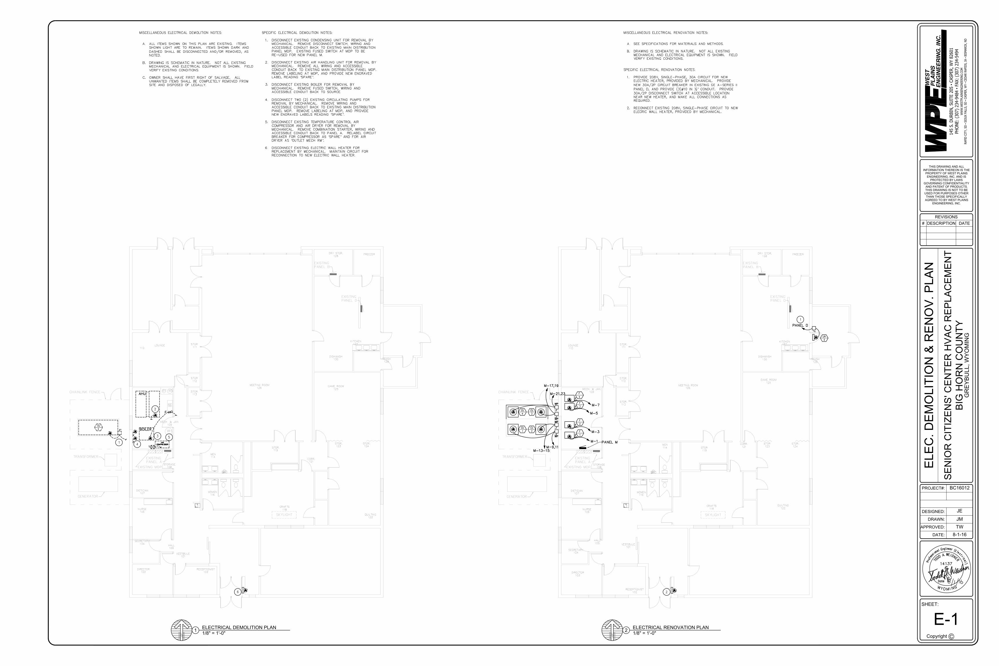
MISCELLANEOUS ELECTRICAL DEMOLITION NOTES: A.ALL ITEMS SHOWN ON THIS PLAN ARE EXISTING. ITEMS ALL ITEMS SHOWN ON THIS PLAN ARE EXISTING. ITEMS SHOWN LIGHT ARE TO REMAIN. ITEMS SHOWN DARK AND DASHED SHALL BE DISCONNECTED AND/OR REMOVED, AS NOTED. B.DRAWING IS SCHEMATIC IN NATURE. NOT ALL EXISTING DRAWING IS SCHEMATIC IN NATURE. NOT ALL EXISTING MECHANICAL AND ELECTRICAL EQUIPMENT IS SHOWN. FIELD VERIFY EXISTING CONDITIONS. C.OWNER SHALL HAVE FIRST RIGHT OF SALVAGE. ALL OWNER SHALL HAVE FIRST RIGHT OF SALVAGE. ALL UNWANTED ITEMS SHALL BE COMPLETELY REMOVED FROM SITE AND DISPOSED OF LEGALLY. SPECIFIC ELECTRICAL DEMOLITION NOTES: 1.DISCONNECT EXISTING CONDENSING UNIT FOR REMOVAL BY DISCONNECT EXISTING CONDENSING UNIT FOR REMOVAL BY MECHANICAL. REMOVE DISCONNECT SWITCH, WIRING AND ACCESSIBLE CONDUIT BACK TO EXISTING MAIN DISTRIBUTION PANEL MDP. EXISTING FUSED SWITCH AT MDP TO BE RE-USED FOR NEW PANEL M. 2.DISCONNECT EXISTING AIR HANDLING UNIT FOR REMOVAL BY DISCONNECT EXISTING AIR HANDLING UNIT FOR REMOVAL BY MECHANICAL. REMOVE ALL WIRING AND ACCESSIBLE CONDUIT BACK TO EXISTING MAIN DISTRIBUTION PANEL MDP. REMOVE LABELING AT MDP, AND PROVIDE NEW ENGRAVED LABEL READING “SPARE”. SPARE”. . 3.DISCONNECT EXISTING BOILER FOR REMOVAL BY DISCONNECT EXISTING BOILER FOR REMOVAL BY MECHANICAL. REMOVE FUSED SWITCH, WIRING AND ACCESSIBLE CONDUIT BACK TO SOURCE. 4.DISCONNECT TWO (2) EXISTING CIRCULATING PUMPS FOR DISCONNECT TWO (2) EXISTING CIRCULATING PUMPS FOR REMOVAL BY MECHANICAL. REMOVE WIRING AND ACCESSIBLE CONDUIT BACK TO EXISTING MAIN DISTRIBUTION PANEL MDP. REMOVE LABELING AT MDP, AND PROVIDE NEW ENGRAVED LABELS READING “SPARE”. SPARE”. . 5.DISCONNECT EXISTING TEMPERATURE CONTROL AIR DISCONNECT EXISTING TEMPERATURE CONTROL AIR COMPRESSOR AND AIR DRYER FOR REMOVAL BY MECHANICAL. REMOVE COMBINATION STARTER, WIRING AND ACCESSIBLE CONDUIT BACK TO PANEL A. RELABEL CIRCUIT BREAKER FOR COMPRESSOR AS “SPARE” AND FOR AIR SPARE” AND FOR AIR AND FOR AIR DRYER AS “OUTLET MECH RM”. OUTLET MECH RM”. . 6.DISCONNECT EXISTING ELECTRIC WALL HEATER FOR DISCONNECT EXISTING ELECTRIC WALL HEATER FOR REPLACEMENT BY MECHANICAL. MAINTAIN CIRCUIT FOR RECONNECTION TO NEW ELECTRIC WALL HEATER.
AutoCAD SHX Text
MISCELLANEOUS ELECTRICAL RENOVATION NOTES: A.SEE SPECIFICATIONS FOR MATERIALS AND METHODS. SEE SPECIFICATIONS FOR MATERIALS AND METHODS. B.DRAWING IS SCHEMATIC IN NATURE. NOT ALL EXISTING DRAWING IS SCHEMATIC IN NATURE. NOT ALL EXISTING MECHANICAL AND ELECTRICAL EQUIPMENT IS SHOWN. FIELD VERIFY EXISTING CONDITIONS. SPECIFIC ELECTRICAL RENOVATION NOTES: 1.PROVIDE 208V, SINGLE-PHASE, 30A CIRCUIT FOR NEW PROVIDE 208V, SINGLE-PHASE, 30A CIRCUIT FOR NEW ELECTRIC HEATER, PROVIDED BY MECHANICAL. PROVIDE NEW 30A/2P CIRCUIT BREAKER IN EXISTING GE A-SERIES II PANEL D, AND PROVIDE (3)#10 IN ½” CONDUIT. PROVIDE CONDUIT. PROVIDE 30A/2P DISCONNECT SWITCH AT ACCESSIBLE LOCATION NEAR NEW HEATER, AND MAKE ALL CONNECTIONS AS REQUIRED. 2.RECONNECT EXISTING 208V, SINGLE-PHASE CIRCUIT TO NEW RECONNECT EXISTING 208V, SINGLE-PHASE CIRCUIT TO NEW ELECRIC WALL HEATER, PROVIDED BY MECHANICAL.

WE
ST
PL
AIN
SE
NG
INE
ER
ING
. IN
C.
WW
W.W
ESTPLAIN
SEN
GIN
EERIN
G.CO
M
RAPID
CITY, SD
▪ SIO
UX FALLS, SD
▪ CASPER, W
Y ▪ CED
AR RAPID
S, IA ▪ BISM
ARCK, N
D
THIS DRAWING AND ALLINFORMATION THEREON IS THE
PROPERTY OF WEST PLAINSENGINEERING, INC. AND IS
PROTECTED BY LAWSGOVERNING CONFIDENTIALITY
AND PATENT OF PRODUCTS.THIS DRAWING IS NOT TO BE
USED FOR PURPOSES OTHERTHAN THOSE SPECIFICALLY
AGREED TO BY WEST PLAINSENGINEERING, INC.
145 S. D
URBIN
, SU
ITE 205 ▪ CASPER, W
Y 82601
PH
ON
E: (307) 234-9484 ▪ FAX: (307) 234-5494
GR
EY
BU
LL, W
YO
MIN
G
8-1-16
BC16012
TWJM
JE
Copyright C
DATE:
APPROVED:
DRAWN:
DESIGNED:
# DATEDESCRIPTIONREVISIONS
SHEET:
PROJECT#:
SE
NIO
R C
ITIZ
EN
S' C
EN
TER
HV
AC
RE
PLA
CE
ME
NT
BIG
HO
RN
CO
UN
TY
ELE
CTR
ICA
L S
CH
ED
ULE
S &
DE
TAIL
S
E-2
AutoCAD SHX Text
%%UPOWER DISTRIBUTION DIAGRAM
AutoCAD SHX Text
NO SCALE
AutoCAD SHX Text
PANEL M 120/208V 3PH/4W 200A MLO
AutoCAD SHX Text
EXISTING MDP
AutoCAD SHX Text
1
AutoCAD SHX Text
MECHANICAL ROOM
AutoCAD SHX Text
STORAGE/ELEC. ROOM
AutoCAD SHX Text
(4)#4/0 & #4/0 & (1) #6 GND. #6 GND. IN 2-1/2" C.
AutoCAD SHX Text
NOTES: 1.CONNECT NEW PANEL FEEDER TO EXISTING 200A/3P CONNECT NEW PANEL FEEDER TO EXISTING 200A/3P FUSED SWITCH FORMERLY SERVING CONDENSING UNIT. REMOVE EXISTING FUSES, AND REPLACE WITH 200A FUSES. REMOVE EXISTING LABEL, AND PROVIDE NEW ENGRAVED LABEL READING "PANEL M".
AutoCAD SHX Text
ECI-1,2,3
AutoCAD SHX Text
RUNS TO PANEL. NUMBERS
AutoCAD SHX Text
ARROWS INDICATE HOME
AutoCAD SHX Text
INDICATE PANEL AND CIRCUIT IN PANEL
AutoCAD SHX Text
DISCONNECT SWITCH
AutoCAD SHX Text
SPECIAL PURPOSE OUTLET OR CONNECTION
AutoCAD SHX Text
CONDUIT IN WALL OR CEILING SPACE,
AutoCAD SHX Text
PANELBOARD OR LOAD CENTER (EXISTING TO REMAIN)
AutoCAD SHX Text
EQUIP. NO.
AutoCAD SHX Text
TYPE OF EQUIP
AutoCAD SHX Text
SEE SCHEDULES
AutoCAD SHX Text
SWITCHBOARD/DISTRIBUTION PANEL SECTION
AutoCAD SHX Text
COMBINATION
AutoCAD SHX Text
STARTER/DISCONNECT
AutoCAD SHX Text
XX
AutoCAD SHX Text
#
AutoCAD SHX Text
ELECTRICAL SYMBOLS
AutoCAD SHX Text
PANELBOARD OR LOAD CENTER
AutoCAD SHX Text
e
AutoCAD SHX Text
l
AutoCAD SHX Text
e
AutoCAD SHX Text
e
AutoCAD SHX Text
n
AutoCAD SHX Text
i
AutoCAD SHX Text
r
AutoCAD SHX Text
E
AutoCAD SHX Text
(
AutoCAD SHX Text
E
AutoCAD SHX Text
a
AutoCAD SHX Text
n
AutoCAD SHX Text
l
AutoCAD SHX Text
g
AutoCAD SHX Text
n
AutoCAD SHX Text
i
AutoCAD SHX Text
o
AutoCAD SHX Text
E
AutoCAD SHX Text
N
AutoCAD SHX Text
D
AutoCAD SHX Text
I
AutoCAD SHX Text
c
AutoCAD SHX Text
i
AutoCAD SHX Text
r
AutoCAD SHX Text
t
AutoCAD SHX Text
E
AutoCAD SHX Text
)
AutoCAD SHX Text
l
AutoCAD SHX Text
a
AutoCAD SHX Text
M
AutoCAD SHX Text
I
AutoCAD SHX Text
N
AutoCAD SHX Text
G
AutoCAD SHX Text
A.
AutoCAD SHX Text
e
AutoCAD SHX Text
f
AutoCAD SHX Text
o
AutoCAD SHX Text
r
AutoCAD SHX Text
P
AutoCAD SHX Text
D
AutoCAD SHX Text
D
AutoCAD SHX Text
O
AutoCAD SHX Text
Y
AutoCAD SHX Text
W
AutoCAD SHX Text
Date
AutoCAD SHX Text
O
AutoCAD SHX Text
14137
AutoCAD SHX Text
s
AutoCAD SHX Text
s
AutoCAD SHX Text
c
AutoCAD SHX Text
W
AutoCAD SHX Text
T
AutoCAD SHX Text
R

PROJECT MANUAL:
BIG HORN COUNTY
SENIOR CENTER
HVAC REPLACEMENTBASIN, WYOMING
PROJECT NO: BC16012
DATE: August 1, 2016
BC16012
TABLE OF CONTENTS
DIVISION 00 - PROCUREMENT AND CONTRACTING REQUIREMENTS
00 1113 ADVERTISEMENT FOR BIDS 200 2113 INSTRUCTIONS TO BIDDERS 400 4100 BID FORM 2
CONTRACT DOCUMENTS
00 700 STANDARD GENERAL CONDITIONS 42
PROJECT FORMS
CERTIFICATE OF INSURANCE G715APPLICATION & CERTIFICATE FOR PAYMENT G702/G703CONTRACTOR’S AFFIDAVIT OF PAYMENT OF DEBT & CLAIMS G706CONTRACTOR’S AFFIDAVIT OF RELEASE OF LIENS G706ACONSENT OF SURETY TO FINAL PAYMENT G707
DIVISION 01 - GENERAL REQUIREMENTS
01 1000 SUMMARY 201 2000 PRICE AND PAYMENT PROCEDURES 401 3000 ADMINISTRATIVE REQUIREMENTS 401 4000 QUALITY REQUIREMENTS 201 6000 PRODUCT REQUIREMENTS 201 7000 EXECUTION AND CLOSEOUT REQUIREMENTS 601 7800 CLOSEOUT SUBMITTALS 4
DIVISION 23 - HEATING, VENTILATING, AND AIR-CONDITIONING (HVAC)
23 0553 IDENTIFICATION FOR HVAC PIPING AND EQUIPMENT 223 0593 TESTING, ADJUSTING, AND BALANCING FOR HVAC 423 0713 DUCT INSULATION 423 3100 HVAC DUCTS AND CASINGS 423 3300 AIR DUCT ACCESSORIES 223 3700 AIR OUTLETS AND INLETS 223 5400 FURNACES 423 6213 PACKAGED AIR-COOLED REFRIGERANT COMPRESSOR AND
CONDENSER UNITS4
DIVISION 26 - ELECTRICAL
26 0050 FIRESTOPPING 226 0501 ELECTRICAL DEMOLITION 226 0519 LOW-VOLTAGE ELECTRICAL POWER CONDUCTORS AND CABLES 426 0526 GROUNDING AND BONDING FOR ELECTRICAL SYSTEMS 426 0529 HANGERS AND SUPPORTS FOR ELECTRICAL SYSTEMS 226 0534 CONDUIT 426 0537 BOXES 226 0553 IDENTIFICATION FOR ELECTRICAL SYSTEMS 226 2416 PANELBOARDS 226 2717 EQUIPMENT WIRING 226 2813 FUSES 226 2818 ENCLOSED SWITCHES 2


ADVERTISEMENT FOR BIDS 00 1113 - 1BC16012
SECTION 00 1113ADVERTISEMENT FOR BIDS
FROM:1.01 THE OWNER (HEREINAFTER REFERRED TO AS OWNER ):
A. Big Horn CountyB. Address:
P.O. Box 31Basin, WY, 82410
1.02 AND THE ENGINEER (HEREINAFTER REFERRED TO AS ENGINEER ):A. West Plains Engineering, Inc.B. Address:
145 S Durbin, Suite 205Casper, WY 82601
1.03 DATE: AUGUST 30, 20161.04 TO: POTENTIAL BIDDERS
A. Your firm is invited to submit an offer under seal to Owner for construction of a HVACReplacement located at 417 South 2nd Street, Greybull WY 82426 before 2:00 pm localstandard time on the 30 day of August, 2016, for:
B. Project: Big Horn County Senior Center - HVAC ReplacementC. Project Description:
1. Replacement of the existing Big Horn County Senior Center HVAC system with a newHVAC system.
D. Bid Documents for a Stipulated Sum contract may be obtained from the office of the DesignProfessional free of charge upon receipt of a refundable deposit, by cash, in the amount of $50for one set.
E. Bidders will be required to provide Bid security in the form of a Bid Bond of a sum no less than10 percent of the Bid Amount.
F. Submit your offer on the Bid Form provided. Bidders may supplement this form as appropriate.G. Your offer will be required to be submitted under a condition of irrevocability for a period of 30
days after submission.H. The Owner reserves the right to accept or reject any or all offers.
1.05 SIGNATUREA. For: Big Horn CountyB. By: _______________________
1. Signed: _______________________________END OF SECTION

00 1113 - 2 ADVERTISEMENT FOR BIDSBC16012
INSTRUCTIONS TO BIDDERS 00 2113 - 1BC16012
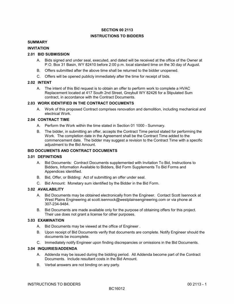
SECTION 00 2113INSTRUCTIONS TO BIDDERS
SUMMARYINVITATION2.01 BID SUBMISSION
A. Bids signed and under seal, executed, and dated will be received at the office of the Owner atP.O. Box 31 Basin, WY 82410 before 2:00 p.m. local standard time on the 30 day of August.
B. Offers submitted after the above time shall be returned to the bidder unopened.C. Offers will be opened publicly immediately after the time for receipt of bids.
2.02 INTENTA. The intent of this Bid request is to obtain an offer to perform work to complete a HVAC
Replacement located at 417 South 2nd Street, Greybull WY 82426 for a Stipulated Sumcontract, in accordance with the Contract Documents.
2.03 WORK IDENTIFIED IN THE CONTRACT DOCUMENTSA. Work of this proposed Contract comprises renovation and demolition, including mechanical and
electrical Work.2.04 CONTRACT TIME
A. Perform the Work within the time stated in Section 01 1000 - Summary.B. The bidder, in submitting an offer, accepts the Contract Time period stated for performing the
Work. The completion date in the Agreement shall be the Contract Time added to thecommencement date. The bidder may suggest a revision to the Contract Time with a specificadjustment to the Bid Amount.
BID DOCUMENTS AND CONTRACT DOCUMENTS3.01 DEFINITIONS
A. Bid Documents: Contract Documents supplemented with Invitation To Bid, Instructions toBidders, Information Available to Bidders, Bid Form Supplements To Bid Forms andAppendices identified.
B. Bid, Offer, or Bidding: Act of submitting an offer under seal.C. Bid Amount: Monetary sum identified by the Bidder in the Bid Form.
3.02 AVAILABILITYA. Bid Documents may be obtained electronically from the Engineer. Contact Scott Isennock at
West Plains Engineering at [email protected] or via phone at307-234-9484.
B. Bid Documents are made available only for the purpose of obtaining offers for this project. Their use does not grant a license for other purposes.
3.03 EXAMINATIONA. Bid Documents may be viewed at the office of Engineer .B. Upon receipt of Bid Documents verify that documents are complete. Notify Engineer should the
documents be incomplete.C. Immediately notify Engineer upon finding discrepancies or omissions in the Bid Documents.
3.04 INQUIRIES/ADDENDAA. Addenda may be issued during the bidding period. All Addenda become part of the Contract
Documents. Include resultant costs in the Bid Amount.B. Verbal answers are not binding on any party.
00 2113 - 2 INSTRUCTIONS TO BIDDERSBC16012
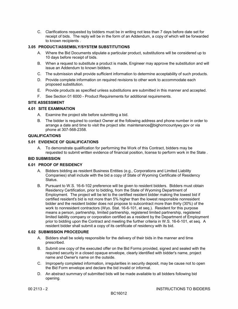
C. Clarifications requested by bidders must be in writing not less than 7 days before date set forreceipt of bids. The reply will be in the form of an Addendum, a copy of which will be forwardedto known recipients .
3.05 PRODUCT/ASSEMBLY/SYSTEM SUBSTITUTIONSA. Where the Bid Documents stipulate a particular product, substitutions will be considered up to
10 days before receipt of bids.B. When a request to substitute a product is made, Engineer may approve the substitution and will
issue an Addendum to known bidders.C. The submission shall provide sufficient information to determine acceptability of such products.D. Provide complete information on required revisions to other work to accommodate each
proposed substitution.E. Provide products as specified unless substitutions are submitted in this manner and accepted.F. See Section 01 6000 - Product Requirements for additional requirements.
SITE ASSESSMENT4.01 SITE EXAMINATION
A. Examine the project site before submitting a bid.B. The bidder is required to contact Owner at the following address and phone number in order to
arrange a date and time to visit the project site: [email protected] or viaphone at 307-568-2358.
QUALIFICATIONS5.01 EVIDENCE OF QUALIFICATIONS
A. To demonstrate qualification for performing the Work of this Contract, bidders may berequested to submit written evidence of financial position, license to perform work in the State .
BID SUBMISSION6.01 PROOF OF RESIDENCY
A. Bidders bidding as resident Business Entities (e.g., Corporations and Limited LiabilityCompanies) shall include with the bid a copy of State of Wyoming Certificate of ResidencyStatus.
B. Pursuant to W.S. 16-6-102 preference will be given to resident bidders. Bidders must obtainResidency Certification, prior to bidding, from the State of Wyoming Department ofEmployment. The project will be let to the certified resident bidder making the lowest bid ifcertified resident's bid is not more than 5% higher than the lowest responsible nonresidentbidder and the resident bidder does not propose to subcontract more than thirty (30%) of thework to nonresident contractors (Wyo. Stat. 16-6-101, et seq.). Resident for this purposemeans a person, partnership, limited partnership, registered limited partnership, registeredlimited liability company or corporation certified as a resident by the Department of Employmentprior to bidding upon the Contract and meeting the further criteria in W.S. 16-6-101, et seq. Aresident bidder shall submit a copy of its certificate of residency with its bid.
6.02 SUBMISSION PROCEDUREA. Bidders shall be solely responsible for the delivery of their bids in the manner and time
prescribed.B. Submit one copy of the executed offer on the Bid Forms provided, signed and sealed with the
required security in a closed opaque envelope, clearly identified with bidder's name, projectname and Owner's name on the outside.
C. Improperly completed information, irregularities in security deposit, may be cause not to openthe Bid Form envelope and declare the bid invalid or informal.
D. An abstract summary of submitted bids will be made available to all bidders following bidopening.

INSTRUCTIONS TO BIDDERS 00 2113- 3BC16012
6.03 BID INELIGIBILITYA. Bids that are unsigned, improperly signed or sealed, conditional, illegible, obscure, contain
arithmetical errors, erasures, alterations, or irregularities of any kind, may at the discretion of theOwner, be declared unacceptable.
B. Bid Forms, Appendices, and enclosures that are improperly prepared may, at the discretion ofOwner, be declared unacceptable.
C. Failure to provide security deposit, bonding or insurance requirements may, at the discretion ofOwner, be waived.
BID ENCLOSURES/REQUIREMENTS7.01 SECURITY DEPOSIT
A. Bids shall be accompanied by a security deposit as follows:1. Bid Bond of a sum no less than 10 percent of the Bid Amount on AIA A310 Bid Bond
Form.B. Endorse the Bid Bond in the name of the Owner as obligee, signed and sealed by the principal
(Contractor) and surety.C. The security deposit will be returned after delivery to the Owner of the required Performance
and Payment Bond(s) by the accepted bidder.D. Include the cost of bid security in the Bid Amount.E. If no contract is awarded, all security deposits will be returned.
7.02 CONSENT OF SURETYA. Submit with the Bid: ________.
7.03 PERFORMANCE ASSURANCEA. Accepted Bidder: Provide a Performance bond as described in 00 7300 - Supplementary
Conditions.B. Include the cost of performance assurance bonds in the Bid Amount.
7.04 INSURANCEA. Provide an executed "Undertaking of Insurance" on the form provided stating their intention to
provide insurance to the bidder in accordance with the insurance requirements of the ContractDocuments.
7.05 BID FORM REQUIREMENTSA. Complete all requested information in the Bid Form and Appendices.
7.06 BID FORM SIGNATUREA. The Bid Form shall be signed by the bidder, as follows:
1. Sole Proprietorship: Signature of sole proprietor in the presence of a witness who will alsosign. Insert the words "Sole Proprietor" under the signature. Affix seal.
2. Partnership: Signature of all partners in the presence of a witness who will also sign. Insert the word "Partner" under each signature. Affix seal to each signature.
3. Corporation: Signature of a duly authorized signing officer(s) in their normal signatures. Insert the officer's capacity in which the signing officer acts, under each signature. Affixthe corporate seal. If the bid is signed by officials other than the president and secretary ofthe company, or the president/secretary/treasurer of the company, a copy of the by-lawresolution of their board of directors authorizing them to do so, must also be submitted withthe Bid Form in the bid envelope.
4. Joint Venture: Each party of the joint venture shall execute the Bid Form under theirrespective seals in a manner appropriate to such party as described above, similar to therequirements of a Partnership.

00 2113 - 4 INSTRUCTIONS TO BIDDERSBC16012
OFFER ACCEPTANCE/REJECTION8.01 DURATION OF OFFER
A. Bids shall remain open to acceptance and shall be irrevocable for a period of thirty (30) daysafter the bid closing date.
8.02 ACCEPTANCE OF OFFERA. Owner reserves the right to accept or reject any or all offers.B. After acceptance by Owner, Engineer on behalf of Owner, will issue to the successful bidder, a
written Bid Acceptance.END OF SECTION
BID FORM 00 4100 - 1BC16012
SECTION 00 4100BID FORM
THE PROJECT AND THE PARTIES1.01 TO:
A. OwnerBig Horn CountyP.O. Box 31Basin, WY 82410
1.02 FOR:A. Big Horn County Senior Center - HVAC Replacement
1. 417 South 2nd Street2. Greybull, WY 82426
1.03 DATE: ______________ (BIDDER TO ENTER DATE)1.04 SUBMITTED BY: (BIDDER TO ENTER NAME AND ADDRESS)
A. Bidder's Full Name _________________________1. Address _________________________2. City, State, Zip_________________________
1.05 OFFERA. Having examined the Place of The Work and all matters referred to in the Instructions to
Bidders and the Contract Documents prepared by West Plains Engineering, Inc. for the abovementioned project, we, the undersigned, hereby offer to enter into a Contract to perform theWork for the Sum of:
B. __________________________________________________________________________________________________________________ dollars($______________________), in lawful money of the United States of America.
C. We have included the required security deposit as required by the Instruction to Bidders.D. We have included the required performance assurance bonds in the Bid Amount as required by
the Instructions to Bidders.E. All applicable federal taxes are included and State of ________ taxes are included in the Bid
Sum.1.06 ACCEPTANCE
A. This offer shall be open to acceptance and is irrevocable for thirty days from the bid closingdate.
B. If this bid is accepted by Owner within the time period stated above, we will:1. Execute the Agreement within seven days of receipt of Notice of Award.2. Furnish the required bonds within seven days of receipt of Notice of Award.3. Commence work within seven days after written Notice to Proceed of this bid.
C. If this bid is accepted within the time stated, and we fail to commence the Work or we fail toprovide the required Bond(s), the security deposit shall be forfeited as damages to Owner byreason of our failure, limited in amount to the lesser of the face value of the security deposit orthe difference between this bid and the bid upon which a Contract is signed.
D. In the event our bid is not accepted within the time stated above, the required security depositshall be returned to the undersigned, in accordance with the provisions of the Instructions toBidders; unless a mutually satisfactory arrangement is made for its retention and validity for anextended period of time.
1.07 CONTRACT TIMEA. If this Bid is accepted, we will:

00 4100 - 2 BID FORMBC16012
B. Complete the Work by the 15th day of November 2016.1.08 ADDENDA
A. The following Addenda have been received. The modifications to the Bid Documents notedbelow have been considered and all costs are included in the Bid Sum.1. Addendum # _______ Dated ________________.2. Addendum # _______ Dated ________________.
1.09 BID FORM SIGNATURE(S)A. The Corporate Seal ofB. ____________________________________________C. (Bidder - print the full name of your firm)D. was hereunto affixed in the presence of:E. ____________________________________________F. (Authorized signing officer, Title)G. (Seal) H. ____________________________________________I. (Authorized signing officer, Title)
END OF BID FORM


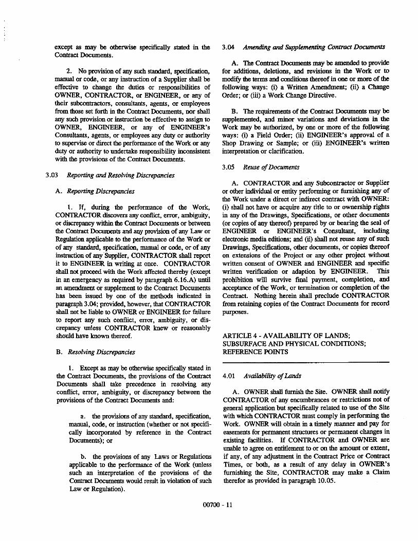
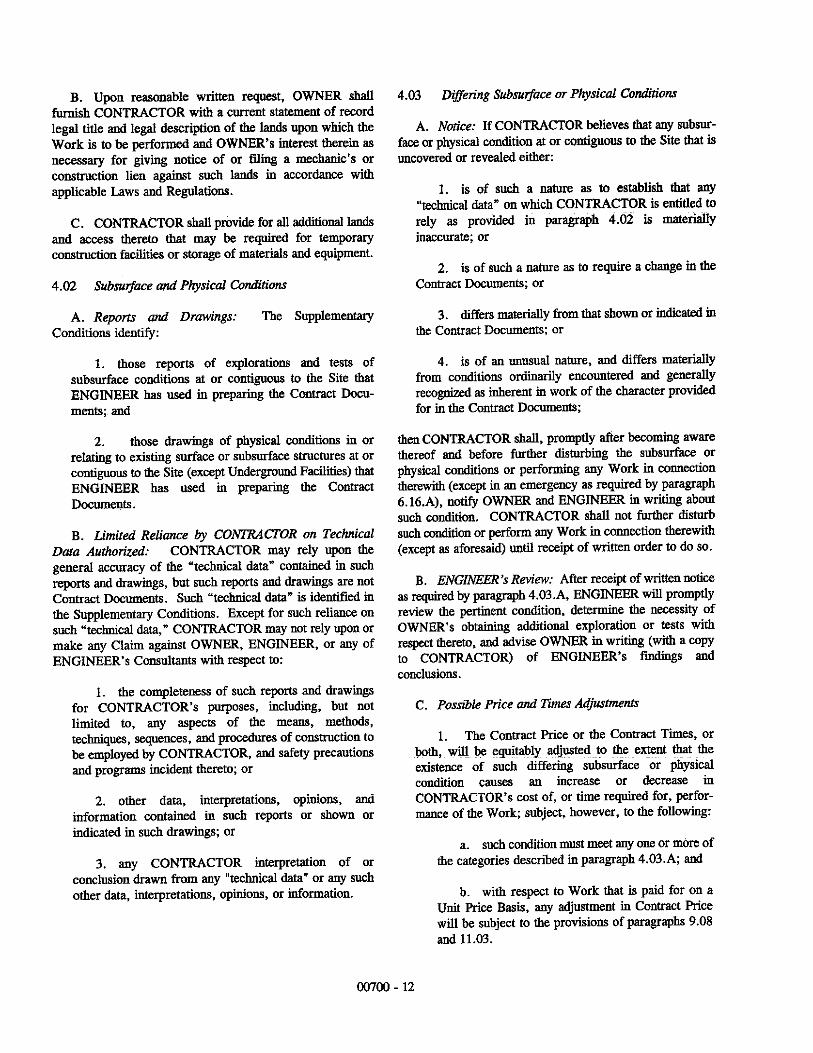


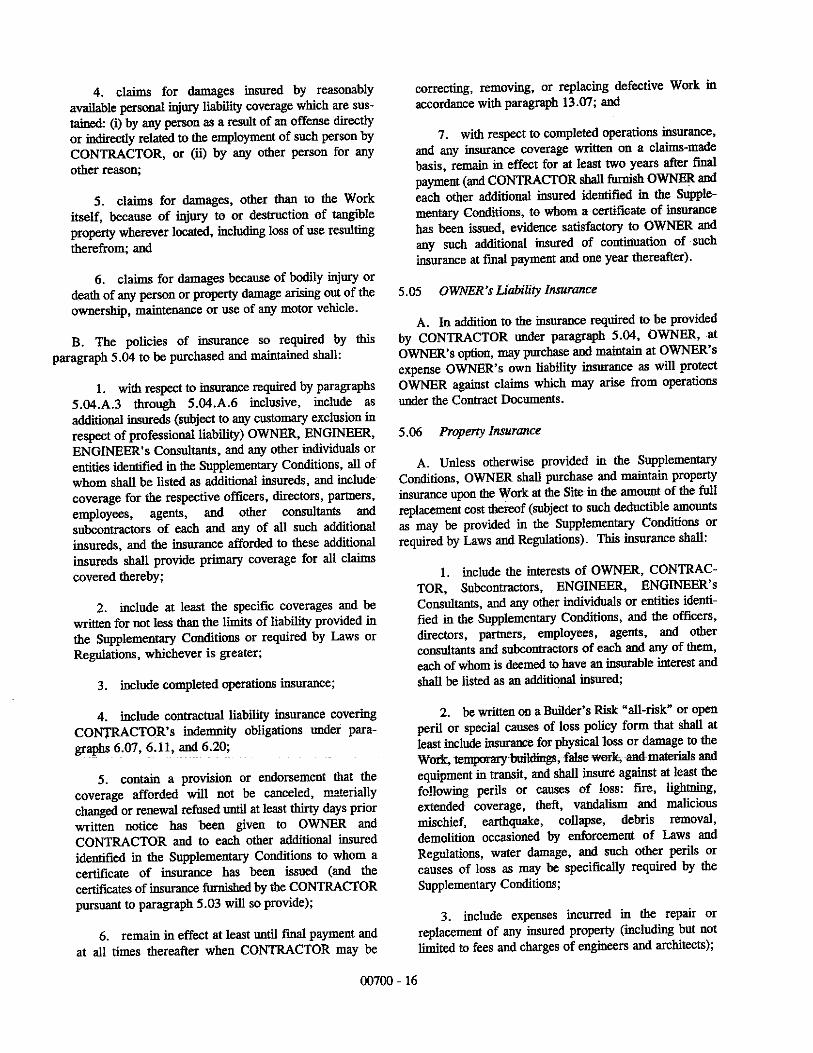


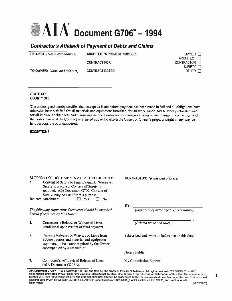


SUMMARY 01 1000 - 1BC16012
SECTION 01 1000SUMMARY
PART 1 GENERAL1.01 PROJECT
A. Project Name: Big Horn County Senior Center - HVAC Replacement.B. Owner's Name: County of Big Horn, Wyoming.C. Engineer's Name: West Plains Engineering, Inc..D. The Project consists of the replacement of the existing HVAC system for the Senior Center
portion of the building by December 31, 2016. The Senior Center portion of the building isapproximately 6,240 square feet..
1.02 CONTRACT DESCRIPTIONA. Contract Type: A single prime contract based on a stipulated price.
1.03 WORK BY OWNERA. Items noted NIC (Not in Contract) will be supplied and installed by Owner before Substantial
Completion. Some items include:1. Existing Ceiling Removal.2. New Ceilings.3. New Lighting.
1.04 OWNER OCCUPANCYA. Owner intends to continue to occupy portions of the existing building during the entire
construction period.B. Cooperate with Owner to minimize conflict and to facilitate Owner's operations.C. Schedule the Work to accommodate Owner occupancy.
1.05 CONTRACTOR USE OF SITE AND PREMISESA. Construction Operations: Limited to areas noted on Drawings. B. Provide access to and from site as required by law and by Owner:
1. Emergency Building Exits During Construction: Keep all exits required by code openduring construction period; provide temporary exit signs if exit routes are temporarilyaltered.
2. Do not obstruct roadways, sidewalks, or other public ways without permit.C. Utility Outages and Shutdown:
1. Prevent accidental disruption of utility services to other facilities.END OF SECTION

01 1000 - 2 SUMMARYBC16012

PRICE AND PAYMENT PROCEDURES 01 2000 - 1BC16012
SECTION 01 2000PRICE AND PAYMENT PROCEDURES
PART 1 GENERAL1.01 SECTION INCLUDES
A. Procedures for preparation and submittal of applications for progress payments.B. Documentation of changes in Contract Sum and Contract Time.C. Change procedures.D. Correlation of Contractor submittals based on changes.E. Procedures for preparation and submittal of application for final payment.
1.02 RELATED REQUIREMENTS1.03 SCHEDULE OF VALUES
A. Electronic media printout including equivalent information will be considered in lieu of standardform specified; submit draft to Engineer for approval.
B. Forms filled out by hand will not be accepted.C. Submit Schedule of Values in duplicate within 15 days after date of Owner-Contractor
Agreement.D. Format: Utilize the Table of Contents of this Project Manual. Identify each line item with number
and title of the specification Section. Identify site mobilization.E. Include within each line item, a direct proportional amount of Contractor's overhead and profit.F. Revise schedule to list approved Change Orders, with each Application For Payment.
1.04 APPLICATIONS FOR PROGRESS PAYMENTSA. Payment Period: Submit at intervals stipulated in the Agreement, but not more than once per
month.B. Form to be used: AIA G702 Application and Certificate for Payment.C. Electronic media printout including equivalent information will be considered in lieu of standard
form specified; submit sample to Engineer for approval.D. Forms filled out by hand will not be accepted.E. For each item, provide a column for listing each of the following:
1. Item Number.2. Description of work.3. Scheduled Values.4. Previous Applications.5. Work in Place and Stored Materials under this Application.6. Authorized Change Orders.7. Total Completed and Stored to Date of Application.8. Percentage of Completion.9. Balance to Finish.10. Retainage.
F. Execute certification by signature of authorized officer.G. Use data from approved Schedule of Values. Provide dollar value in each column for each line
item for portion of work performed and for stored products.H. List each authorized Change Order as a separate line item, listing Change Order number and
dollar amount as for an original item of Work.I. Submit three copies of each Application for Payment.J. Include the following with the application:
1. Transmittal letter as specified for Submittals in Section 01 3000.

01 2000 - 2 PRICE AND PAYMENT PROCEDURESBC16012
2. Construction progress schedule, revised and current as specified in Section 01 3000.3. Partial release of liens from major Subcontractors and vendors.
K. When Engineer requires substantiating information, submit data justifying dollar amounts inquestion. Provide one copy of data with cover letter for each copy of submittal. Showapplication number and date, and line item by number and description.
1.05 MODIFICATION PROCEDURESA. Submit name of the individual authorized to receive change documents and who will be
responsible for informing others in Contractor's employ or subcontractors of changes to theContract Documents.
B. For minor changes not involving an adjustment to the Contract Sum or Contract Time, Engineerwill issue instructions directly to Contractor.
C. For other required changes, Engineer will issue a document signed by Owner instructingContractor to proceed with the change, for subsequent inclusion in a Change Order.1. The document will describe the required changes and will designate method of
determining any change in Contract Sum or Contract Time.2. Promptly execute the change.
D. For changes for which advance pricing is desired, Engineer will issue a document that includesa detailed description of a proposed change with supplementary or revised drawings andspecifications, a change in Contract Time for executing the change with a stipulation of anyovertime work required and the period of time during which the requested price will beconsidered valid. Contractor shall prepare and submit a fixed price quotation within 7 days.
E. Contractor may propose a change by submitting a request for change to Engineer, describingthe proposed change and its full effect on the Work, with a statement describing the reason forthe change, and the effect on the Contract Sum and Contract Time with full documentation anda statement describing the effect on Work by separate or other contractors. Document anyrequested substitutions in accordance with Section 01 6000.
F. Computation of Change in Contract Amount: As specified in the Agreement and Conditions ofthe Contract.1. For change requested by Engineer for work falling under a fixed price contract, the amount
will be based on Contractor's price quotation.2. For change requested by Contractor, the amount will be based on the Contractor's request
for a Change Order as approved by Engineer.G. Substantiation of Costs: Provide full information required for evaluation.
1. On request, provide the following data:a. Quantities of products, labor, and equipment.b. Taxes, insurance, and bonds.c. Overhead and profit.d. Justification for any change in Contract Time.e. Credit for deletions from Contract, similarly documented.
2. Support each claim for additional costs with additional information:a. Origin and date of claim.b. Dates and times work was performed, and by whom.c. Time records and wage rates paid.d. Invoices and receipts for products, equipment, and subcontracts, similarly
documented.3. For Time and Material work, submit itemized account and supporting data after completion
of change, within time limits indicated in the Conditions of the Contract.H. Execution of Change Orders: Engineer will issue Change Orders for signatures of parties as
provided in the Conditions of the Contract.I. After execution of Change Order, promptly revise Schedule of Values and Application for
Payment forms to record each authorized Change Order as a separate line item and adjust theContract Sum.
PRICE AND PAYMENT PROCEDURES 01 2000- 3BC16012
J. Promptly revise progress schedules to reflect any change in Contract Time, revisesub-schedules to adjust times for other items of work affected by the change, and resubmit.
K. Promptly enter changes in Project Record Documents.1.06 APPLICATION FOR FINAL PAYMENT
A. Prepare Application for Final Payment as specified for progress payments, identifying totaladjusted Contract Sum, previous payments, and sum remaining due.
B. Application for Final Payment will not be considered until the following have been accomplished:1. All closeout procedures specified in Section 01 7000.
END OF SECTION

01 2000 - 4 PRICE AND PAYMENT PROCEDURESBC16012
ADMINISTRATIVE REQUIREMENTS 01 3000 - 1BC16012
SECTION 01 3000ADMINISTRATIVE REQUIREMENTS
PART 1 GENERAL1.01 SECTION INCLUDES
A. Construction progress schedule.B. Progress photographs.C. Submittals for review, information, and project closeout.D. Submittal procedures.
1.02 RELATED REQUIREMENTSA. Section 01 7000 - Execution and Closeout Requirements: Additional coordination requirements.B. Section 01 7800 - Closeout Submittals: Project record documents.
PART 2 PRODUCTS - NOT USEDPART 3 EXECUTION3.01 CONSTRUCTION PROGRESS SCHEDULE
A. Within 10 days after date of the Agreement, submit preliminary schedule defining plannedoperations for the first 60 days of Work, with a general outline for remainder of Work.
B. If preliminary schedule requires revision after review, submit revised schedule within 10 days.C. Within 20 days after review of preliminary schedule, submit draft of proposed complete
schedule for review.1. Include written certification that major contractors have reviewed and accepted proposed
schedule.D. Within 10 days after joint review, submit complete schedule.E. Submit updated schedule with each Application for Payment.
3.02 PROGRESS PHOTOGRAPHSA. Maintain one set of all photographs at project site for reference; same copies as submitted,
identified as such.B. Photography Type: Digital; electronic files.
3.03 SUBMITTALS FOR REVIEWA. When the following are specified in individual sections, submit them for review:
1. Product data.2. Shop drawings.
B. Submit to Engineer for review for the limited purpose of checking for conformance withinformation given and the design concept expressed in the contract documents.
C. After review, provide copies and distribute in accordance with SUBMITTAL PROCEDURESarticle below and for record documents purposes described in Section 01 7800 - CloseoutSubmittals.
3.04 SUBMITTALS FOR INFORMATIONA. When the following are specified in individual sections, submit them for information:
1. Design data.2. Certificates.3. Test reports.4. Inspection reports.5. Manufacturer's instructions.6. Manufacturer's field reports.7. Other types indicated.

01 3000 - 2 ADMINISTRATIVE REQUIREMENTSBC16012
B. Submit for Engineer's knowledge as contract administrator or for Owner. No action will betaken.
3.05 SUBMITTALS FOR PROJECT CLOSEOUTA. Submit Correction Punch List for Substantial Completion.B. Submit Final Correction Punch List for Substantial Completion.C. When the following are specified in individual sections, submit them at project closeout:
1. Project record documents.2. Operation and maintenance data.3. Warranties.4. Bonds.5. Other types as indicated.
D. Submit for Owner's benefit during and after project completion.3.06 NUMBER OF COPIES OF SUBMITTALS
A. Electronic Documents: Submit one electronic copy in PDF format; an electronically-marked upfile will be returned. Create PDFs at native size and right-side up; illegible files will be rejected.
3.07 SUBMITTAL PROCEDURESA. Shop Drawing Procedures:
1. Prepare accurate, drawn-to-scale, original shop drawing documentation by interpreting theContract Documents and coordinating related Work.
2. Generic, non-project specific information submitted as shop drawings do not meet therequirements for shop drawings.
B. Transmit each submittal with a copy of approved submittal form.C. Sequentially number the transmittal form. Revise submittals with original number and a
sequential alphabetic suffix.D. Identify Project, Contractor, Subcontractor or supplier; pertinent drawing and detail number, and
specification section number, as appropriate on each copy.E. Apply Contractor's stamp, signed or initialed certifying that review, approval, verification of
Products required, field dimensions, adjacent construction Work, and coordination ofinformation is in accordance with the requirements of the Work and Contract Documents.
F. Schedule submittals to expedite the Project, and coordinate submission of related items.G. For each submittal for review, allow 15 days excluding delivery time to and from the Contractor.H. Identify variations from Contract Documents and Product or system limitations that may be
detrimental to successful performance of the completed Work.I. Provide space for Contractor and Engineer review stamps.J. When revised for resubmission, identify all changes made since previous submission.K. Distribute reviewed submittals as appropriate. Instruct parties to promptly report any inability to
comply with requirements.L. Submittals not requested will not be recognized or processed.
END OF SECTION
QUALITY REQUIREMENTS 01 4000 - 1BC16012
SECTION 01 4000QUALITY REQUIREMENTS
PART 1 GENERAL1.01 SECTION INCLUDES
A. Testing and inspection agencies and services.B. Control of installation.C. Tolerances.D. Manufacturers' field services.E. Defect Assessment.
1.02 RELATED REQUIREMENTS1.03 TESTING AND INSPECTION AGENCIES AND SERVICESPART 3 EXECUTION2.01 CONTROL OF INSTALLATION
A. Monitor quality control over suppliers, manufacturers, products, services, site conditions, andworkmanship, to produce Work of specified quality.
B. Comply with manufacturers' instructions, including each step in sequence.C. Should manufacturers' instructions conflict with Contract Documents, request clarification from
Engineer before proceeding.D. Comply with specified standards as minimum quality for the Work except where more stringent
tolerances, codes, or specified requirements indicate higher standards or more preciseworkmanship.
E. Have Work performed by persons qualified to produce required and specified quality.F. Verify that field measurements are as indicated on shop drawings or as instructed by the
manufacturer.G. Secure products in place with positive anchorage devices designed and sized to withstand
stresses, vibration, physical distortion, and disfigurement.2.02 TOLERANCES
A. Monitor fabrication and installation tolerance control of products to produce acceptable Work. Do not permit tolerances to accumulate.
B. Comply with manufacturers' tolerances. Should manufacturers' tolerances conflict with ContractDocuments, request clarification from Engineer before proceeding.
C. Adjust products to appropriate dimensions; position before securing products in place.2.03 TESTING AND INSPECTION
A. Testing Agency Duties:1. Provide qualified personnel at site. Cooperate with Engineer and Contractor in
performance of services.2. Perform specified sampling and testing of products in accordance with specified
standards.3. Ascertain compliance of materials and mixes with requirements of Contract Documents.4. Promptly notify Engineer and Contractor of observed irregularities or non-conformance of
Work or products.5. Perform additional tests and inspections required by Engineer.6. Submit reports of all tests/inspections specified.
B. Limits on Testing/Inspection Agency Authority:1. Agency may not release, revoke, alter, or enlarge on requirements of Contract Documents.2. Agency may not approve or accept any portion of the Work.
01 4000 - 2 QUALITY REQUIREMENTSBC16012
3. Agency may not assume any duties of Contractor.4. Agency has no authority to stop the Work.
C. Contractor Responsibilities:1. Deliver to agency at designated location, adequate samples of materials proposed to be
used that require testing, along with proposed mix designs.2. Cooperate with laboratory personnel, and provide access to the Work and to
manufacturers' facilities.3. Provide incidental labor and facilities:
a. To provide access to Work to be tested/inspected.b. To obtain and handle samples at the site or at source of Products to be
tested/inspected.c. To facilitate tests/inspections.d. To provide storage and curing of test samples.
4. Notify Engineer and laboratory 24 hours prior to expected time for operations requiringtesting/inspection services.
5. Employ services of an independent qualified testing laboratory and pay for additionalsamples, tests, and inspections required by Contractor beyond specified requirements.
6. Arrange with Owner's agency and pay for additional samples, tests, and inspectionsrequired by Contractor beyond specified requirements.
D. Re-testing required because of non-conformance to specified requirements shall be performedby the same agency on instructions by Engineer.
E. Re-testing required because of non-conformance to specified requirements shall be paid for byContractor.
2.04 MANUFACTURERS' FIELD SERVICESA. When specified in individual specification sections, require material or product suppliers or
manufacturers to provide qualified staff personnel to observe site conditions, conditions ofsurfaces and installation, quality of workmanship, start-up of equipment, test, adjust andbalance of equipment as applicable, and to initiate instructions when necessary.
B. Report observations and site decisions or instructions given to applicators or installers that aresupplemental or contrary to manufacturers' written instructions.
2.05 DEFECT ASSESSMENTA. Replace Work or portions of the Work not conforming to specified requirements.B. If, in the opinion of Engineer, it is not practical to remove and replace the Work, Engineer will
direct an appropriate remedy or adjust payment.END OF SECTION

PRODUCT REQUIREMENTS 01 6000 - 1BC16012
SECTION 01 6000PRODUCT REQUIREMENTS
PART 1 GENERAL1.01 SECTION INCLUDES
A. Transportation, handling, storage and protection.B. Product option requirements.C. Substitution limitations and procedures.D. Maintenance materials, including extra materials, spare parts, tools, and software.
1.02 RELATED REQUIREMENTSA. Section 01 4000 - Quality Requirements: Product quality monitoring.
1.03 SUBMITTALSA. Product Data Submittals: Submit manufacturer's standard published data. Mark each copy to
identify applicable products, models, options, and other data. Supplement manufacturers'standard data to provide information specific to this Project.
B. Shop Drawing Submittals: Prepared specifically for this Project; indicate utility and electricalcharacteristics, utility connection requirements, and location of utility outlets for service forfunctional equipment and appliances.
PART 2 PRODUCTS2.01 NEW PRODUCTS
A. Provide new products unless specifically required or permitted by the Contract Documents.B. DO NOT USE products having any of the following characteristics:
1. Made using or containing CFC's or HCFC's.2. Containing lead, cadmium, asbestos.
2.02 PRODUCT OPTIONSA. Products Specified by Reference Standards or by Description Only: Use any product meeting
those standards or description.B. Products Specified by Naming One or More Manufacturers: Use a product of one of the
manufacturers named and meeting specifications, no options or substitutions allowed.C. Products Specified by Naming One or More Manufacturers with a Provision for Substitutions:
Submit a request for substitution for any manufacturer not named.2.03 MAINTENANCE MATERIALS
A. Furnish extra materials, spare parts, tools, and software of types and in quantities specified inindividual specification sections.
B. Deliver to Project site; obtain receipt prior to final payment.PART 3 EXECUTION3.01 SUBSTITUTION PROCEDURES
A. Document each request with complete data substantiating compliance of proposed substitutionwith Contract Documents.
B. A request for substitution constitutes a representation that the submitter:1. Has investigated proposed product and determined that it meets or exceeds the quality
level of the specified product.2. Agrees to provide the same warranty for the substitution as for the specified product.3. Agrees to coordinate installation and make changes to other Work that may be required
for the Work to be complete with no additional cost to Owner.4. Waives claims for additional costs or time extension that may subsequently become
apparent.

01 6000 - 2 PRODUCT REQUIREMENTSBC16012
C. Substitutions will not be considered when they are indicated or implied on shop drawing orproduct data submittals, without separate written request, or when acceptance will requirerevision to the Contract Documents.
D. Substitution Submittal Procedure (after contract award):1. Submit three copies of request for substitution for consideration. Limit each request to one
proposed substitution.2. Submit shop drawings, product data, and certified test results attesting to the proposed
product equivalence. Burden of proof is on proposer.3. The Engineer will notify Contractor in writing of decision to accept or reject request.
3.02 TRANSPORTATION AND HANDLINGA. Package products for shipment in manner to prevent damage; for equipment, package to avoid
loss of factory calibration.B. If special precautions are required, attach instructions prominently and legibly on outside of
packaging.C. Coordinate schedule of product delivery to designated prepared areas in order to minimize site
storage time and potential damage to stored materials.D. Transport and handle products in accordance with manufacturer's instructions.E. Transport materials in covered trucks to prevent contamination of product and littering of
surrounding areas.F. Promptly inspect shipments to ensure that products comply with requirements, quantities are
correct, and products are undamaged.G. Provide equipment and personnel to handle products by methods to prevent soiling,
disfigurement, or damage, and to minimize handling.H. Arrange for the return of packing materials, such as wood pallets, where economically feasible.
3.03 STORAGE AND PROTECTIONA. Designate receiving/storage areas for incoming products so that they are delivered according to
installation schedule and placed convenient to work area in order to minimize waste due toexcessive materials handling and misapplication.
B. Store and protect products in accordance with manufacturers' instructions.C. Store with seals and labels intact and legible.D. Store sensitive products in weather tight, climate controlled, enclosures in an environment
favorable to product.E. For exterior storage of fabricated products, place on sloped supports above ground.F. Protect products from damage or deterioration due to construction operations, weather,
precipitation, humidity, temperature, sunlight and ultraviolet light, dirt, dust, and othercontaminants.
G. Comply with manufacturer's warranty conditions, if any.H. Cover products subject to deterioration with impervious sheet covering. Provide ventilation to
prevent condensation and degradation of products.I. Prevent contact with material that may cause corrosion, discoloration, or staining.J. Provide equipment and personnel to store products by methods to prevent soiling,
disfigurement, or damage.K. Arrange storage of products to permit access for inspection. Periodically inspect to verify
products are undamaged and are maintained in acceptable condition.END OF SECTION

EXECUTION AND CLOSEOUT REQUIREMENTS 01 7000 - 1BC16012
SECTION 01 7000EXECUTION AND CLOSEOUT REQUIREMENTS
PART 1 GENERAL1.01 SECTION INCLUDES
A. Examination, preparation, and general installation procedures.B. Requirements for alterations work, including selective demolition, except removal, disposal,
and/or remediation of hazardous materials and toxic substances.C. Cutting and patching.D. Cleaning and protection.E. Starting of systems and equipment.F. Demonstration and instruction of Owner personnel.G. Closeout procedures, including Contractor's Correction Punch List, except payment procedures.H. General requirements for maintenance service.
1.02 RELATED REQUIREMENTSA. Section 01 1000 - Summary: Limitations on working in existing building; continued occupancy;
work sequence; identification of salvaged and relocated materials.B. Section 01 3000 - Administrative Requirements: Submittals procedures, Electronic document
submittal service.C. Section 01 4000 - Quality Requirements: Testing and inspection procedures.D. Section 07 8400 - Firestopping.
1.03 SUBMITTALSA. See Section 01 3000 - Administrative Requirements, for submittal procedures.B. Cutting and Patching: Submit written request in advance of cutting or alteration that affects:
1. Structural integrity of any element of Project.2. Integrity of weather exposed or moisture resistant element.3. Efficiency, maintenance, or safety of any operational element.4. Visual qualities of sight exposed elements.5. Work of Owner or separate Contractor.
C. Project Record Documents: Accurately record actual locations of capped and active utilities.1.04 QUALIFICATIONS
A. For demolition work, employ a firm specializing in the type of work required.1. Minimum of 3 years of documented experience.
1.05 PROJECT CONDITIONSA. Use of explosives is not permitted.B. Ventilate enclosed areas to assist cure of materials, to dissipate humidity, and to prevent
accumulation of dust, fumes, vapors, or gases.1.06 COORDINATION
A. Coordinate scheduling, submittals, and work of the various sections of the Project Manual toensure efficient and orderly sequence of installation of interdependent construction elements,with provisions for accommodating items installed later.
B. Notify affected utility companies and comply with their requirements.C. Verify that utility requirements and characteristics of new operating equipment are compatible
with building utilities. Coordinate work of various sections having interdependent responsibilitiesfor installing, connecting to, and placing in service, such equipment.

01 7000 - 2 EXECUTION AND CLOSEOUT REQUIREMENTSBC16012
D. Coordinate space requirements, supports, and installation of mechanical and electrical workthat are indicated diagrammatically on Drawings. Follow routing shown for pipes, ducts, andconduit, as closely as practicable; place runs parallel with lines of building. Utilize spacesefficiently to maximize accessibility for other installations, for maintenance, and for repairs.
E. In finished areas except as otherwise indicated, conceal pipes, ducts, and wiring within theconstruction. Coordinate locations of fixtures and outlets with finish elements.
F. Coordinate completion and clean-up of work of separate sections.G. After Owner occupancy of premises, coordinate access to site for correction of defective work
and work not in accordance with Contract Documents, to minimize disruption of Owner'sactivities.
PART 2 PRODUCTS2.01 PATCHING MATERIALS
A. New Materials: As specified in product sections; match existing products and work for patchingand extending work.
B. Type and Quality of Existing Products: Determine by inspecting and testing products wherenecessary, referring to existing work as a standard.
C. Product Substitution: For any proposed change in materials, submit request for substitutiondescribed in Section 01 6000 - Product Requirements.
PART 3 EXECUTION3.01 EXAMINATION
A. Verify that existing site conditions and substrate surfaces are acceptable for subsequent work. Start of work means acceptance of existing conditions.
B. Verify that existing substrate is capable of structural support or attachment of new work beingapplied or attached.
C. Examine and verify specific conditions described in individual specification sections.D. Take field measurements before confirming product orders or beginning fabrication, to minimize
waste due to over-ordering or misfabrication.E. Verify that utility services are available, of the correct characteristics, and in the correct
locations.F. Prior to Cutting: Examine existing conditions prior to commencing work, including elements
subject to damage or movement during cutting and patching. After uncovering existing work,assess conditions affecting performance of work. Beginning of cutting or patching meansacceptance of existing conditions.
3.02 PREPARATIONA. Clean substrate surfaces prior to applying next material or substance.B. Seal cracks or openings of substrate prior to applying next material or substance.C. Apply manufacturer required or recommended substrate primer, sealer, or conditioner prior to
applying any new material or substance in contact or bond.3.03 GENERAL INSTALLATION REQUIREMENTS
A. Install products as specified in individual sections, in accordance with manufacturer'sinstructions and recommendations, and so as to avoid waste due to necessity for replacement.
B. Make vertical elements plumb and horizontal elements level, unless otherwise indicated.C. Install equipment and fittings plumb and level, neatly aligned with adjacent vertical and
horizontal lines, unless otherwise indicated.3.04 ALTERATIONS
A. Drawings showing existing construction and utilities are based on casual field observation andexisting record documents only.
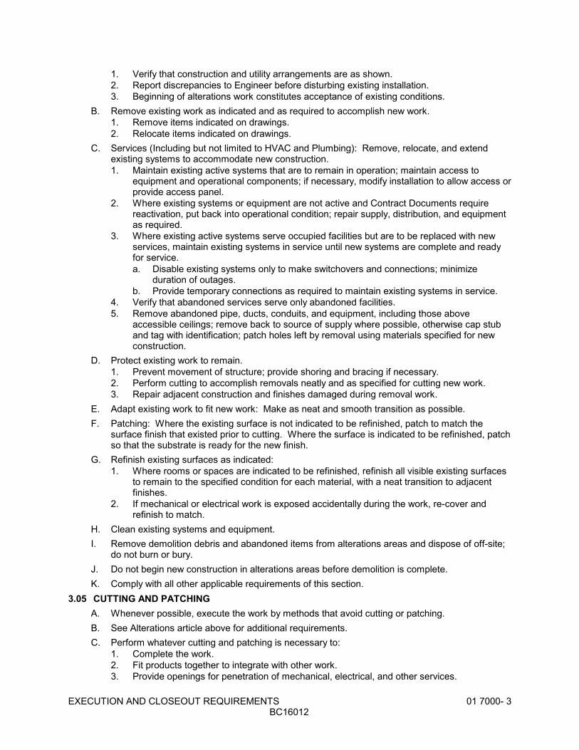
EXECUTION AND CLOSEOUT REQUIREMENTS 01 7000- 3BC16012
1. Verify that construction and utility arrangements are as shown.2. Report discrepancies to Engineer before disturbing existing installation.3. Beginning of alterations work constitutes acceptance of existing conditions.
B. Remove existing work as indicated and as required to accomplish new work.1. Remove items indicated on drawings.2. Relocate items indicated on drawings.
C. Services (Including but not limited to HVAC and Plumbing): Remove, relocate, and extendexisting systems to accommodate new construction.1. Maintain existing active systems that are to remain in operation; maintain access to
equipment and operational components; if necessary, modify installation to allow access orprovide access panel.
2. Where existing systems or equipment are not active and Contract Documents requirereactivation, put back into operational condition; repair supply, distribution, and equipmentas required.
3. Where existing active systems serve occupied facilities but are to be replaced with newservices, maintain existing systems in service until new systems are complete and readyfor service.a. Disable existing systems only to make switchovers and connections; minimize
duration of outages.b. Provide temporary connections as required to maintain existing systems in service.
4. Verify that abandoned services serve only abandoned facilities.5. Remove abandoned pipe, ducts, conduits, and equipment, including those above
accessible ceilings; remove back to source of supply where possible, otherwise cap stuband tag with identification; patch holes left by removal using materials specified for newconstruction.
D. Protect existing work to remain.1. Prevent movement of structure; provide shoring and bracing if necessary.2. Perform cutting to accomplish removals neatly and as specified for cutting new work.3. Repair adjacent construction and finishes damaged during removal work.
E. Adapt existing work to fit new work: Make as neat and smooth transition as possible.F. Patching: Where the existing surface is not indicated to be refinished, patch to match the
surface finish that existed prior to cutting. Where the surface is indicated to be refinished, patchso that the substrate is ready for the new finish.
G. Refinish existing surfaces as indicated:1. Where rooms or spaces are indicated to be refinished, refinish all visible existing surfaces
to remain to the specified condition for each material, with a neat transition to adjacentfinishes.
2. If mechanical or electrical work is exposed accidentally during the work, re-cover andrefinish to match.
H. Clean existing systems and equipment.I. Remove demolition debris and abandoned items from alterations areas and dispose of off-site;
do not burn or bury.J. Do not begin new construction in alterations areas before demolition is complete.K. Comply with all other applicable requirements of this section.
3.05 CUTTING AND PATCHINGA. Whenever possible, execute the work by methods that avoid cutting or patching.B. See Alterations article above for additional requirements.C. Perform whatever cutting and patching is necessary to:
1. Complete the work.2. Fit products together to integrate with other work.3. Provide openings for penetration of mechanical, electrical, and other services.
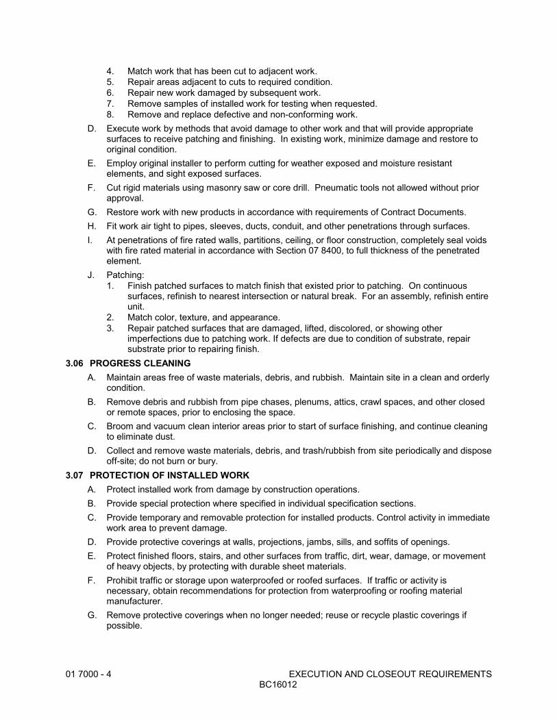
01 7000 - 4 EXECUTION AND CLOSEOUT REQUIREMENTSBC16012
4. Match work that has been cut to adjacent work.5. Repair areas adjacent to cuts to required condition.6. Repair new work damaged by subsequent work.7. Remove samples of installed work for testing when requested.8. Remove and replace defective and non-conforming work.
D. Execute work by methods that avoid damage to other work and that will provide appropriatesurfaces to receive patching and finishing. In existing work, minimize damage and restore tooriginal condition.
E. Employ original installer to perform cutting for weather exposed and moisture resistantelements, and sight exposed surfaces.
F. Cut rigid materials using masonry saw or core drill. Pneumatic tools not allowed without priorapproval.
G. Restore work with new products in accordance with requirements of Contract Documents.H. Fit work air tight to pipes, sleeves, ducts, conduit, and other penetrations through surfaces.I. At penetrations of fire rated walls, partitions, ceiling, or floor construction, completely seal voids
with fire rated material in accordance with Section 07 8400, to full thickness of the penetratedelement.
J. Patching:1. Finish patched surfaces to match finish that existed prior to patching. On continuous
surfaces, refinish to nearest intersection or natural break. For an assembly, refinish entireunit.
2. Match color, texture, and appearance.3. Repair patched surfaces that are damaged, lifted, discolored, or showing other
imperfections due to patching work. If defects are due to condition of substrate, repairsubstrate prior to repairing finish.
3.06 PROGRESS CLEANINGA. Maintain areas free of waste materials, debris, and rubbish. Maintain site in a clean and orderly
condition.B. Remove debris and rubbish from pipe chases, plenums, attics, crawl spaces, and other closed
or remote spaces, prior to enclosing the space.C. Broom and vacuum clean interior areas prior to start of surface finishing, and continue cleaning
to eliminate dust.D. Collect and remove waste materials, debris, and trash/rubbish from site periodically and dispose
off-site; do not burn or bury.3.07 PROTECTION OF INSTALLED WORK
A. Protect installed work from damage by construction operations.B. Provide special protection where specified in individual specification sections.C. Provide temporary and removable protection for installed products. Control activity in immediate
work area to prevent damage.D. Provide protective coverings at walls, projections, jambs, sills, and soffits of openings.E. Protect finished floors, stairs, and other surfaces from traffic, dirt, wear, damage, or movement
of heavy objects, by protecting with durable sheet materials.F. Prohibit traffic or storage upon waterproofed or roofed surfaces. If traffic or activity is
necessary, obtain recommendations for protection from waterproofing or roofing materialmanufacturer.
G. Remove protective coverings when no longer needed; reuse or recycle plastic coverings ifpossible.
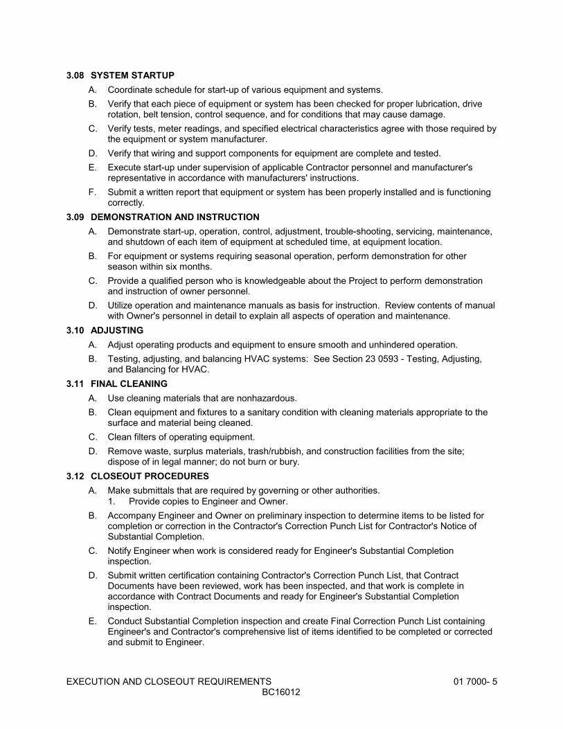
EXECUTION AND CLOSEOUT REQUIREMENTS 01 7000- 5BC16012
3.08 SYSTEM STARTUPA. Coordinate schedule for start-up of various equipment and systems.B. Verify that each piece of equipment or system has been checked for proper lubrication, drive
rotation, belt tension, control sequence, and for conditions that may cause damage.C. Verify tests, meter readings, and specified electrical characteristics agree with those required by
the equipment or system manufacturer.D. Verify that wiring and support components for equipment are complete and tested.E. Execute start-up under supervision of applicable Contractor personnel and manufacturer's
representative in accordance with manufacturers' instructions.F. Submit a written report that equipment or system has been properly installed and is functioning
correctly.3.09 DEMONSTRATION AND INSTRUCTION
A. Demonstrate start-up, operation, control, adjustment, trouble-shooting, servicing, maintenance,and shutdown of each item of equipment at scheduled time, at equipment location.
B. For equipment or systems requiring seasonal operation, perform demonstration for otherseason within six months.
C. Provide a qualified person who is knowledgeable about the Project to perform demonstrationand instruction of owner personnel.
D. Utilize operation and maintenance manuals as basis for instruction. Review contents of manualwith Owner's personnel in detail to explain all aspects of operation and maintenance.
3.10 ADJUSTINGA. Adjust operating products and equipment to ensure smooth and unhindered operation.B. Testing, adjusting, and balancing HVAC systems: See Section 23 0593 - Testing, Adjusting,
and Balancing for HVAC.3.11 FINAL CLEANING
A. Use cleaning materials that are nonhazardous.B. Clean equipment and fixtures to a sanitary condition with cleaning materials appropriate to the
surface and material being cleaned.C. Clean filters of operating equipment.D. Remove waste, surplus materials, trash/rubbish, and construction facilities from the site;
dispose of in legal manner; do not burn or bury.3.12 CLOSEOUT PROCEDURES
A. Make submittals that are required by governing or other authorities.1. Provide copies to Engineer and Owner.
B. Accompany Engineer and Owner on preliminary inspection to determine items to be listed forcompletion or correction in the Contractor's Correction Punch List for Contractor's Notice ofSubstantial Completion.
C. Notify Engineer when work is considered ready for Engineer's Substantial Completioninspection.
D. Submit written certification containing Contractor's Correction Punch List, that ContractDocuments have been reviewed, work has been inspected, and that work is complete inaccordance with Contract Documents and ready for Engineer's Substantial Completioninspection.
E. Conduct Substantial Completion inspection and create Final Correction Punch List containingEngineer's and Contractor's comprehensive list of items identified to be completed or correctedand submit to Engineer.
01 7000 - 6 EXECUTION AND CLOSEOUT REQUIREMENTSBC16012
F. Correct items of work listed in Final Correction Punch List and comply with requirements foraccess to Owner-occupied areas.
G. Notify Engineer when work is considered finally complete and ready for Engineer's SubstantialCompletion final inspection.
H. Complete items of work determined by Engineer listed in executed Certificate of SubstantialCompletion.
3.13 MAINTENANCEA. Provide service and maintenance of components indicated in specification sections.B. Maintenance Period: As indicated in specification sections or, if not indicated, not less than one
year from the Date of Substantial Completion or the length of the specified warranty, whicheveris longer.
C. Maintenance service shall not be assigned or transferred to any agent or subcontractor withoutprior written consent of the Owner.
END OF SECTION

CLOSEOUT SUBMITTALS 01 7800 - 1BC16012
SECTION 01 7800CLOSEOUT SUBMITTALS
PART 1 GENERAL1.01 SECTION INCLUDES
A. Project Record Documents.B. Operation and Maintenance Data.C. Warranties and bonds.
1.02 RELATED REQUIREMENTSA. Section 01 3000 - Administrative Requirements: Submittals procedures, shop drawings,
product data, and samples.B. Section 01 7000 - Execution and Closeout Requirements: Contract closeout procedures.C. Individual Product Sections: Specific requirements for operation and maintenance data.D. Individual Product Sections: Warranties required for specific products or Work.
1.03 SUBMITTALSA. Project Record Documents: Submit documents to Engineer with claim for final Application for
Payment.B. Operation and Maintenance Data:
1. Submit two copies of preliminary draft or proposed formats and outlines of contents beforestart of Work. Engineer will review draft and return one copy with comments.
2. For equipment, or component parts of equipment put into service during construction andoperated by Owner, submit completed documents within ten days after acceptance.
3. Submit one copy of completed documents 15 days prior to final inspection. This copy willbe reviewed and returned after final inspection, with Engineer comments. Revise contentof all document sets as required prior to final submission.
4. Submit two sets of revised final documents in final form within 10 days after finalinspection.
C. Warranties and Bonds:1. For equipment or component parts of equipment put into service during construction with
Owner's permission, submit documents within 10 days after acceptance.2. Make other submittals within 10 days after Date of Substantial Completion, prior to final
Application for Payment.3. For items of Work for which acceptance is delayed beyond Date of Substantial
Completion, submit within 10 days after acceptance, listing the date of acceptance as thebeginning of the warranty period.
PART 3 EXECUTION2.01 PROJECT RECORD DOCUMENTS
A. Maintain on site one set of the following record documents; record actual revisions to the Work:1. Drawings.2. Specifications.3. Addenda.4. Change Orders and other modifications to the Contract.5. Reviewed shop drawings, product data, and samples.6. Manufacturer's instruction for assembly, installation, and adjusting.
B. Ensure entries are complete and accurate, enabling future reference by Owner.C. Store record documents separate from documents used for construction.D. Record information concurrent with construction progress.E. Specifications: Legibly mark and record at each product section description of actual products
installed, including the following:

01 7800 - 2 CLOSEOUT SUBMITTALSBC16012
1. Product substitutions or alternates utilized.2. Changes made by Addenda and modifications.
F. Record Drawings and Shop Drawings: Legibly mark each item to record actual constructionincluding:1. Field changes of dimension and detail.2. Details not on original Contract drawings.
2.02 OPERATION AND MAINTENANCE DATAA. Source Data: For each product or system, list names, addresses and telephone numbers of
Subcontractors and suppliers, including local source of supplies and replacement parts.B. Product Data: Mark each sheet to clearly identify specific products and component parts, and
data applicable to installation. Delete inapplicable information.C. Drawings: Supplement product data to illustrate relations of component parts of equipment and
systems, to show control and flow diagrams. Do not use Project Record Documents asmaintenance drawings.
D. Typed Text: As required to supplement product data. Provide logical sequence of instructionsfor each procedure, incorporating manufacturer's instructions.
2.03 OPERATION AND MAINTENANCE DATA FOR EQUIPMENT AND SYSTEMSA. For Each Item of Equipment and Each System:
1. Description of unit or system, and component parts.2. Identify function, normal operating characteristics, and limiting conditions.3. Include performance curves, with engineering data and tests.4. Complete nomenclature and model number of replaceable parts.
B. Where additional instructions are required, beyond the manufacturer's standard printedinstructions, have instructions prepared by personnel experienced in the operation andmaintenance of the specific products.
C. Operating Procedures: Include start-up, break-in, and routine normal operating instructions andsequences. Include regulation, control, stopping, shut-down, and emergency instructions. Include summer, winter, and any special operating instructions.
D. Maintenance Requirements: Include routine procedures and guide for preventativemaintenance and trouble shooting; disassembly, repair, and reassembly instructions; andalignment, adjusting, balancing, and checking instructions.
E. Provide servicing and lubrication schedule, and list of lubricants required.F. Include manufacturer's printed operation and maintenance instructions.G. Include sequence of operation by controls manufacturer.H. Provide original manufacturer's parts list, illustrations, assembly drawings, and diagrams
required for maintenance.I. Include test and balancing reports.J. Additional Requirements: As specified in individual product specification sections.
2.04 ASSEMBLY OF OPERATION AND MAINTENANCE MANUALSA. Assemble operation and maintenance data into durable manuals for Owner's personnel use,
with data arranged in the same sequence as, and identified by, the specification sections.B. Where systems involve more than one specification section, provide separate tabbed divider for
each system.C. Binders: Commercial quality, 8-1/2 by 11 inch three D side ring binders with durable plastic
covers; 2 inch maximum ring size. When multiple binders are used, correlate data into relatedconsistent groupings.
D. Cover: Identify each binder with typed or printed title OPERATION AND MAINTENANCEINSTRUCTIONS; identify title of Project; identify subject matter of contents.

CLOSEOUT SUBMITTALS 01 7800- 3BC16012
E. Project Directory: Title and address of Project; names, addresses, and telephone numbers ofEngineer, Consultants, Contractor and subcontractors, with names of responsible parties.
F. Tables of Contents: List every item separated by a divider, using the same identification as onthe divider tab; where multiple volumes are required, include all volumes Tables of Contents ineach volume, with the current volume clearly identified.
G. Dividers: Provide tabbed dividers for each separate product and system; identify the contentson the divider tab; immediately following the divider tab include a description of product andmajor component parts of equipment.
H. Text: Manufacturer's printed data, or typewritten data on 20 pound paper.I. Drawings: Provide with reinforced punched binder tab. Bind in with text; fold larger drawings to
size of text pages.J. Arrangement of Contents: Organize each volume in parts as follows:
1. Project Directory.2. Table of Contents, of all volumes, and of this volume.3. Operation and Maintenance Data: Arranged by system, then by product category.
a. Source data.b. Operation and maintenance data.c. Field quality control data.d. Photocopies of warranties and bonds.
2.05 WARRANTIES AND BONDSA. Obtain warranties and bonds, executed in duplicate by responsible Subcontractors, suppliers,
and manufacturers, within 10 days after completion of the applicable item of work. Except foritems put into use with Owner's permission, leave date of beginning of time of warranty untilDate of Substantial completion is determined.
B. Verify that documents are in proper form, contain full information, and are notarized.C. Co-execute submittals when required.D. Retain warranties and bonds until time specified for submittal.E. Manual: Bind in commercial quality 8-1/2 by 11 inch three D side ring binders with durable
plastic covers.F. Cover: Identify each binder with typed or printed title WARRANTIES AND BONDS, with title of
Project; name, address and telephone number of Contractor and equipment supplier; and nameof responsible company principal.
G. Table of Contents: Neatly typed, in the sequence of the Table of Contents of the ProjectManual, with each item identified with the number and title of the specification section in whichspecified, and the name of product or work item.
H. Separate each warranty or bond with index tab sheets keyed to the Table of Contents listing. Provide full information, using separate typed sheets as necessary. List Subcontractor,supplier, and manufacturer, with name, address, and telephone number of responsible principal.
END OF SECTION

01 7800 - 4 CLOSEOUT SUBMITTALSBC16012

IDENTIFICATION FOR HVAC PIPING AND EQUIPMENT 23 0553 - 1BC16012
SECTION 23 0553IDENTIFICATION FOR HVAC PIPING AND EQUIPMENT
PART 1 GENERAL1.01 SECTION INCLUDES
A. Nameplates.B. Tags.
1.02 REFERENCE STANDARDSA. ASTM D709 - Standard Specification for Laminated Thermosetting Materials; 2001
(Reapproved 2007).PART 2 PRODUCTS2.01 IDENTIFICATION APPLICATIONS
A. Air Handling Units: Nameplates.B. Small-sized Equipment: Tags.C. Thermostats: Nameplates.
2.02 NAMEPLATESA. Letter Color: White.B. Letter Height: 1/4 inch.C. Background Color: Black.D. Plastic: Conform to ASTM D709.
2.03 TAGSA. Metal Tags: Brass with stamped letters; tag size minimum 1-1/2 inch diameter with smooth
edges.PART 3 EXECUTION3.01 PREPARATION
A. Degrease and clean surfaces to receive adhesive for identification materials.3.02 INSTALLATION
A. Install nameplates with corrosive-resistant mechanical fasteners, or adhesive. Apply withsufficient adhesive to ensure permanent adhesion and seal with clear lacquer.
B. Install tags with corrosion resistant chain.END OF SECTION

23 0553 - 2 IDENTIFICATION FOR HVAC PIPING AND EQUIPMENTBC16012

TESTING, ADJUSTING, AND BALANCING FOR HVAC 23 0593 - 1BC16012
SECTION 23 0593TESTING, ADJUSTING, AND BALANCING FOR HVAC
PART 1 GENERAL1.01 SECTION INCLUDES
A. Testing, adjustment, and balancing of air systems.1.02 REFERENCE STANDARDS
A. AABC MN-1 - AABC National Standards for Total System Balance; Associated Air BalanceCouncil; 2002.
B. NEBB (TAB) - Procedural Standards for Testing Adjusting Balancing of Environmental Systems;National Environmental Balancing Bureau; 2005, Seventh Edition.
1.03 SUBMITTALS A. See Section 01 3000 - Administrative Requirements, for submittal procedures.B. Final Report: Indicate deficiencies in systems that would prevent proper testing, adjusting, and
balancing of systems and equipment to achieve specified performance.1. Submit draft copies of report for review prior to final acceptance of Project. Provide final
copies for Engineer and for inclusion in operating and maintenance manuals.2. Provide reports in soft cover, letter size, 3-ring binder manuals, complete with index page
and indexing tabs, with cover identification at front and side. Include set of reduceddrawings with air outlets and equipment identified to correspond with data sheets, andindicating thermostat locations.
3. Include actual instrument list, with manufacturer name, serial number, and date ofcalibration.
4. Form of Test Reports: Where the TAB standard being followed recommends a reportformat use that; otherwise, follow ASHRAE Std 111.
5. Units of Measure: Report data in I-P (inch-pound) units only.6. Include the following on the title page of each report:
a. Name of Testing, Adjusting, and Balancing Agency.b. Address of Testing, Adjusting, and Balancing Agency.c. Telephone number of Testing, Adjusting, and Balancing Agency.d. Project name.e. Project location.f. Project Engineer.g. Project Engineer.h. Project Contractor.i. Project altitude.j. Report date.
PART 2 PRODUCTS - NOT USEDPART 3 EXECUTION3.01 GENERAL REQUIREMENTS
A. Perform total system balance in accordance with one of the following:1. AABC MN-1, AABC National Standards for Total System Balance.2. NEBB Procedural Standards for Testing Adjusting Balancing of Environmental Systems.
B. Begin work after completion of systems to be tested, adjusted, or balanced and complete workprior to Substantial Completion of the project.
C. Where HVAC systems and/or components interface with life safety systems, including fire andsmoke detection, alarm, and control, coordinate scheduling and testing and inspectionprocedures with the authorities having jurisdiction.
D. TAB Agency Qualifications:
23 0593 - 2 TESTING, ADJUSTING, AND BALANCING FOR HVACBC16012
1. Company specializing in the testing, adjusting, and balancing of systems specified in thissection.
2. Having minimum of three years documented experience.3. Certified by one of the following:
a. AABC, Associated Air Balance Council: www.aabchq.com; upon completion submitAABC National Performance Guaranty.
b. NEBB, National Environmental Balancing Bureau: www.nebb.org.E. TAB Supervisor Qualifications: Certified by same organization as TAB agency.
3.02 EXAMINATION A. Verify that systems are complete and operable before commencing work. Ensure the following
conditions:1. Systems are started and operating in a safe and normal condition.2. Temperature control systems are installed complete and operable.3. Proper thermal overload protection is in place for electrical equipment.4. Final filters are clean and in place. If required, install temporary media in addition to final
filters.5. Duct systems are clean of debris.6. Fans are rotating correctly.7. Fire and volume dampers are in place and open.8. Air coil fins are cleaned and combed.9. Access doors are closed and duct end caps are in place.10. Air outlets are installed and connected.11. Duct system leakage is minimized.
B. Submit field reports. Report defects and deficiencies that will or could prevent proper systembalance.
C. Beginning of work means acceptance of existing conditions.3.03 ADJUSTMENT TOLERANCES
A. Air Handling Systems: Adjust to within plus or minus 5 percent of design for supply systemsand plus or minus 10 percent of design for return and exhaust systems.
B. Air Outlets and Inlets: Adjust total to within plus 10 percent and minus 5 percent of design tospace. Adjust outlets and inlets in space to within plus or minus 10 percent of design.
3.04 RECORDING AND ADJUSTING A. Ensure recorded data represents actual measured or observed conditions.B. Permanently mark settings of valves, dampers, and other adjustment devices allowing settings
to be restored. Set and lock memory stops.C. Mark on the drawings the locations where traverse and other critical measurements were taken
and cross reference the location in the final report.D. After adjustment, take measurements to verify balance has not been disrupted or that such
disruption has been rectified.E. Leave systems in proper working order, replacing belt guards, closing access doors, closing
doors to electrical switch boxes, and restoring thermostats to specified settings.F. Check and adjust systems approximately six months after final acceptance and submit report.
3.05 AIR SYSTEM PROCEDUREA. Adjust air handling and distribution systems to provide required or design supply, return, and
exhaust air quantities at site altitude.B. Make air quantity measurements in ducts by Pitot tube traverse of entire cross sectional area of
duct.C. Measure air quantities at air inlets and outlets.
TESTING, ADJUSTING, AND BALANCING FOR HVAC 23 0593- 3BC16012
D. Adjust distribution system to obtain uniform space temperatures free from objectionable draftsand noise.
E. Use volume control devices to regulate air quantities only to extend that adjustments do notcreate objectionable air motion or sound levels. Effect volume control by duct internal devicessuch as dampers and splitters.
F. Vary total system air quantities by adjustment of fan speeds. Provide drive changes required. Vary branch air quantities by damper regulation.
G. Provide system schematic with required and actual air quantities recorded at each outlet or inlet.H. Measure static air pressure conditions on air supply units, including filter and coil pressure
drops, and total pressure across the fan. Make allowances for 50 percent loading of filters.I. Adjust outside air automatic dampers, outside air, return air, and exhaust dampers for design
conditions.J. Measure building static pressure and adjust supply, return, and exhaust air systems to provide
required relationship between each to maintain approximately 0.05 inches positive staticpressure near the building entries.
3.06 SCOPEA. Test, adjust, and balance the following:
1. Forced Air Furnaces2. Fans 3. Air Inlets and Outlets
3.07 MINIMUM DATA TO BE REPORTEDA. Combustion Equipment:
1. Model number2. Serial number3. Firing rate4. Heat input5. Burner manifold gas pressure
B. Air Cooled Condensers:1. Identification/number 2. Location 3. Manufacturer 4. Model number5. Serial number6. Number of compressors
C. Air Moving Equipment:1. Location 2. Manufacturer 3. Model number4. Serial number5. Arrangement/Class/Discharge 6. Air flow, specified and actual7. Return air flow, specified and actual8. Outside air flow, specified and actual9. Total static pressure (total external), specified and actual10. Sheave Make/Size/Bore11. Number of Belts/Make/Size12. Fan RPM
D. Duct Traverses:1. System zone/branch2. Duct size
23 0593 - 4 TESTING, ADJUSTING, AND BALANCING FOR HVACBC16012
3. Area 4. Design air flow5. Test air flow6. Duct static pressure
E. Air Distribution Tests:1. Air terminal number2. Room number/location3. Terminal type4. Terminal size5. Design air flow6. Test (final) air flow7. Percent of design air flow
END OF SECTION
DUCT INSULATION 23 0713 - 1BC16012
SECTION 23 0713DUCT INSULATION
PART 1 GENERAL1.01 SECTION INCLUDES
A. Duct insulation.B. Duct Liner.
1.02 REFERENCE STANDARDSA. ASTM C518 - Standard Test Method for Steady-State Thermal Transmission Properties by
Means of the Heat Flow Meter Apparatus; 2010.B. ASTM C553 - Specification for Mineral Fiber Blanket Thermal Insulation for Commercial and
Industrial Applications; 2011.C. ASTM C916 - Standard Specification for Adhesives for Duct Thermal Insulation; 1985
(Reapproved 2007).D. ASTM C1338 - Standard Test Method for Determining Fungi Resistance of Insulation Materials
and Facings; 2008.E. ASTM E84 - Standard Test Method for Surface Burning Characteristics of Building Materials;
2012.F. ASTM E96/E96M - Standard Test Methods for Water Vapor Transmission of Materials; 2010.G. ASTM G21 - Standard Practice for Determining Resistance of Synthetic Polymeric Materials to
Fungi; 2009.H. NFPA 255 - Standard Method of Test of Surface Burning Characteristics of Building Materials;
National Fire Protection Association; 2006.I. SMACNA (DCS) - HVAC Duct Construction Standards; Sheet Metal and Air Conditioning
Contractors' National Association; 2005.1.03 SUBMITTALS
A. See Section 01 3000 - Administrative Requirements, for submittal procedures.B. Product Data: Provide product description, thermal characteristics, list of materials and
thickness for each service, and locations.1.04 QUALITY ASSURANCE
A. Manufacturer Qualifications: Company specializing in manufacturing products of the typespecified in this section with not less than three years of documented experience.
B. Applicator Qualifications: Company specializing in performing the type of work specified in thissection, with minimum three years of experience and approved by manufacturer.
1.05 DELIVERY, STORAGE, AND HANDLINGA. Accept materials on site in original factory packaging, labelled with manufacturer's identification,
including product density and thickness.B. Protect insulation from weather and construction traffic, dirt, water, chemical, and mechanical
damage, by storing in original wrapping.1.06 FIELD CONDITIONS
A. Maintain ambient temperatures and conditions required by manufacturers of adhesives,mastics, and insulation cements.
B. Maintain temperature during and after installation for minimum period of 24 hours.

23 0713 - 2 DUCT INSULATIONBC16012
PART 2 PRODUCTS2.01 REQUIREMENTS FOR ALL PRODUCTS OF THIS SECTION
A. Surface Burning Characteristics: Flame spread/Smoke developed index of 25/50, maximum,when tested in accordance with ASTM E84, NFPA 255, or UL 723.
2.02 GLASS FIBER, FLEXIBLEA. Manufacturer:
1. Knauf Insulation: www.knaufusa.com.2. Johns Manville Corporation: www.jm.com.3. Owens Corning Corp: www.owenscorning.com.4. CertainTeed Corporation: www.certainteed.com.5. Substitutions: See Section 01 6000 - Product Requirements.
B. Insulation: ASTM C553; flexible, noncombustible blanket.1. 'K' value: 0.36 at 75 degrees F, when tested in accordance with ASTM C518.2. Maximum Service Temperature: 450 degrees F.3. Maximum Water Vapor Sorption: 5.0 percent by weight.
C. Vapor Barrier Jacket:1. Kraft paper with glass fiber yarn and bonded to aluminized film.2. Moisture Vapor Permeability: 0.02 perm inch, when tested in accordance with ASTM
E96/E96M.3. Secure with pressure sensitive tape.
D. Vapor Barrier Tape:1. Kraft paper reinforced with glass fiber yarn and bonded to aluminized film, with pressure
sensitive rubber based adhesive.E. Tie Wire: Annealed steel, 16 gage.
2.03 DUCT LINERA. Manufacturers:
1. Knauf Insulation: www.knaufusa.com.2. Johns Manville Corporation: www.jm.com.3. Owens Corning Corp: www.owenscorning.com.4. CertainTeed Corporation: www.certainteed.com.5. Substitutions: See Section 01 6000 - Product Requirements.
B. Insulation: Non-corrosive, incombustible glass fiber complying with ASTM C1071; rigid board;impregnated surface and edges coated with poly vinyl acetate polymer, acrylic polymer, or blackcomposite.1. Fungi Resistance: ASTM G21.2. Apparent Thermal Conductivity: Maximum of 0.31 at 75 degrees F.3. Service Temperature: Up to 250 degrees F.4. Rated Velocity on Coated Air Side for Air Erosion: 5,000 fpm, minimum.5. Minimum Noise Reduction Coefficients:
a. 1 inch Thickness: 0.45.C. Adhesive: Waterproof, fire-retardant type, ASTM C916.D. Liner Fasteners: Galvanized steel, self-adhesive pad with integral head.
PART 3 EXECUTION3.01 EXAMINATION
A. Verify that ducts have been tested before applying insulation materials.B. Verify that surfaces are clean, foreign material removed, and dry.
3.02 INSTALLATIONA. Install in accordance with manufacturer's instructions.
DUCT INSULATION 23 0713- 3BC16012
B. Install in accordance with NAIMA National Insulation Standards.C. Insulated ducts conveying air below ambient temperature:
1. Provide insulation with vapor barrier jackets.2. Finish with tape and vapor barrier jacket.3. Continue insulation through walls, sleeves, hangers, and other duct penetrations.4. Insulate entire system including fittings, joints, flanges, fire dampers, flexible connections,
and expansion joints.D. Duct Liner Application:
1. Adhere insulation with adhesive for 100 percent coverage.2. Secure insulation with mechanical liner fasteners. Refer to SMACNA HVAC Duct
Construction Standards for spacing.3. Seal and smooth joints. Seal and coat transverse joints.4. Seal liner surface penetrations with adhesive.5. Duct dimensions indicated are net inside dimensions required for air flow. Increase duct
size to allow for insulation thickness.3.03 SCHEDULES
A. Outside Air Intake Ducts:1. Flexible Glass Fiber Duct Insulation.2. Thickness: 1-1/2 inches
B. Supply Ducts:1. Round Ducts
a. Flexible Glass Fiber Duct Insulation.b. Thickness: 1-1/2 inches
2. Rectangular Ductsa. Duct Linerb. Thickness: 1 inch.
C. Return Ducts:1. Round Ducts
a. None.2. Rectangular Ducts to minimum 20 feet upstream of furnace
a. Duct Linerb. Thickness: 1 inch.
END OF SECTION

23 0713 - 4 DUCT INSULATIONBC16012

HVAC DUCTS AND CASINGS 23 3100 - 1BC16012
SECTION 23 3100HVAC DUCTS AND CASINGS
PART 1 GENERAL1.01 SECTION INCLUDES
A. Metal ductwork.1.02 RELATED REQUIREMENTS
A. Section 07 8400 - Firestopping.B. Section 23 0713 - Duct Insulation: External insulation and duct liner.C. Section 23 3300 - Air Duct Accessories.D. Section 23 3700 - Air Outlets and Inlets.E. Section 23 0593 - Testing, Adjusting, and Balancing for HVAC.
1.03 REFERENCE STANDARDSA. ASTM A36/A36M - Standard Specification for Carbon Structural Steel; 2008.B. ASTM A653/A653M - Standard Specification for Steel Sheet, Zinc-Coated (Galvanized) or
Zinc-Iron Alloy-Coated (Galvannealed) by the Hot-Dip Process; 2011.C. ASTM E84 - Standard Test Method for Surface Burning Characteristics of Building Materials;
2012.D. NFPA 90A - Standard for the Installation of Air-Conditioning and Ventilating Systems; National
Fire Protection Association; 2012.E. SMACNA (DCS) - HVAC Duct Construction Standards; 2005.
1.04 SUBMITTALSA. See Section 01 3000 - Administrative Requirements, for submittal procedures.B. Project Record Documents: Record actual locations of ducts and duct fittings. Record changes
in fitting location and type. Show additional fittings used.1.05 QUALITY ASSURANCE
A. Manufacturer Qualifications: Company specializing in manufacturing the type of productsspecified in this section, with minimum three years of documented experience.
B. Installer Qualifications: Company specializing in performing the type of work specified in thissection, with minimum three years of documented experience.
1.06 REGULATORY REQUIREMENTSA. Construct ductwork to NFPA 90A standards.
1.07 FIELD CONDITIONSA. Do not install duct sealants when temperatures are less than those recommended by sealant
manufacturers.B. Maintain temperatures within acceptable range during and after installation of duct sealants.
PART 2 PRODUCTS2.01 DUCT ASSEMBLIES
A. All Ducts: Galvanized steel, unless otherwise indicated.B. Low Pressure Supply (System with Cooling Coils): 1 inch w.g. pressure class, galvanized steel.C. Return and Relief: 1 inch w.g. pressure class, galvanized steel.D. Outside Air Intake: 1 inch w.g. pressure class, galvanized steel.
2.02 MATERIALSA. Galvanized Steel for Ducts: Hot-dipped galvanized steel sheet, ASTM A653/A653M FS Type B,
with G90/Z275 coating.

23 3100 - 2 HVAC DUCTS AND CASINGSBC16012
B. Joint Sealers and Sealants: Non-hardening, water resistant, mildew and mold resistant.1. Type: Heavy mastic or liquid used alone or with tape, suitable for joint configuration and
compatible with substrates, and recommended by manufacturer for pressure class ofducts.
2. VOC Content: Not more than 250 g/L, excluding water.3. Surface Burning Characteristics: Flame spread of zero, smoke developed of zero, when
tested in accordance with ASTM E84.4. For Use With Flexible Ducts: UL labeled.
C. Hanger Rod: ASTM A36/A36M; steel, galvanized; threaded both ends, threaded one end, orcontinuously threaded.
2.03 DUCTWORK FABRICATIONA. Fabricate and support in accordance with SMACNA HVAC Duct Construction Standards and as
indicated.B. Provide duct material, gages, reinforcing, and sealing for operating pressures indicated.C. Construct T's, bends, and elbows with radius of not less than 1-1/2 times width of duct on
centerline. Where not possible and where rectangular elbows must be used, provide air foilturning vanes of perforated metal with glass fiber insulation.
D. Increase duct sizes gradually, not exceeding 15 degrees divergence wherever possible;maximum 30 degrees divergence upstream of equipment and 45 degrees convergencedownstream.
E. Fabricate continuously welded round and oval duct fittings in accordance with SMACNA HVACDuct Construction Standards.
F. Where ducts are connected to exterior wall louvers and duct outlet is smaller than louver frame,provide blank-out panels sealing louver area around duct. Use same material as duct, paintedblack on exterior side; seal to louver frame and duct.
2.04 MANUFACTURED DUCTWORK AND FITTINGSA. Flexible Ducts: Two ply vinyl film supported by helically wound spring steel wire.
1. Pressure Rating: 10 inches WG positive and 1.0 inches WG negative.2. Maximum Velocity: 4000 fpm.3. Temperature Range: -10 degrees F to 160 degrees F.
PART 3 EXECUTION3.01 INSTALLATION
A. Install, support, and seal ducts in accordance with SMACNA HVAC Duct ConstructionStandards.
B. Install in accordance with manufacturer's instructions.C. During construction provide temporary closures of metal or taped polyethylene on open
ductwork to prevent construction dust from entering ductwork system.D. Flexible Ducts: Connect to metal ducts with adhesive.E. Duct sizes indicated are inside clear dimensions. For lined ducts, maintain sizes inside lining.F. Provide openings in ductwork where required to accommodate thermometers and controllers.
Provide pilot tube openings where required for testing of systems, complete with metal can withspring device or screw to ensure against air leakage. Where openings are provided in insulatedductwork, install insulation material inside a metal ring.
G. Locate ducts with sufficient space around equipment to allow normal operating andmaintenance activities.
H. Use crimp joints with or without bead for joining round duct sizes 8 inch and smaller with crimpin direction of air flow.
I. Use double nuts and lock washers on threaded rod supports.
HVAC DUCTS AND CASINGS 23 3100- 3BC16012
J. At exterior wall louvers, seal duct to louver frame and install blank-out panels.END OF SECTION

23 3100 - 4 HVAC DUCTS AND CASINGSBC16012

AIR DUCT ACCESSORIES 23 3300 - 1BC16012
SECTION 23 3300AIR DUCT ACCESSORIES
PART 1 GENERAL1.01 SECTION INCLUDES
A. Backdraft dampers - metal.B. Duct access doors.C. Duct test holes.D. Flexible duct connections.E. Volume control dampers.
1.02 RELATED REQUIREMENTSA. Section 23 3100 - HVAC Ducts and Casings.
1.03 REFERENCE STANDARDSA. NFPA 90A - Standard for the Installation of Air-Conditioning and Ventilating Systems; National
Fire Protection Association; 2012.B. SMACNA (DCS) - HVAC Duct Construction Standards; 2005.
1.04 SUBMITTALSA. See Section 01 3000 - Administrative Requirements, for submittal procedures.B. Project Record Drawings: Record actual locations of access doors and test holes.
1.05 QUALITY ASSURANCEA. Manufacturer Qualifications: Company specializing in manufacturing the type of products
specified in this section, with minimum three years of documented experience.B. Products Requiring Electrical Connection: Listed and classified by Underwriters Laboratories
Inc. as suitable for the purpose specified and indicated.1.06 DELIVERY, STORAGE, AND HANDLING
A. Protect dampers from damage to operating linkages and blades.PART 2 PRODUCTS2.01 BACKDRAFT DAMPERS - METAL
A. Gravity Backdraft Dampers, Size 18 x 18 inches or Smaller, Furnished with Air MovingEquipment: Air moving equipment manufacturer's standard construction.
B. Multi-Blade, Parallel Action Gravity Balanced Backdraft Dampers: Galvanized steel, with centerpivoted blades of maximum 6 inch width, with felt or flexible vinyl sealed edges, linked togetherin rattle-free manner with 90 degree stop, steel ball bearings, and plated steel pivot pin;adjustment device to permit setting for varying differential static pressure.
2.02 DUCT ACCESS DOORSA. Fabricate in accordance with SMACNA HVAC Duct Construction Standards and as indicated.B. Access doors with sheet metal screw fasteners are not acceptable.
2.03 DUCT TEST HOLESA. Temporary Test Holes: Cut or drill in ducts as required. Cap with neat patches, neoprene
plugs, threaded plugs, or threaded or twist-on metal caps.2.04 FLEXIBLE DUCT CONNECTIONS
A. Fabricate in accordance with SMACNA HVAC Duct Construction Standards and as indicated.B. Flexible Duct Connections: Fabric crimped into metal edging strip.
1. Fabric: UL listed fire-retardant neoprene coated woven glass fiber fabric to NFPA 90A,minimum density 30 oz per sq yd.

23 3300 - 2 AIR DUCT ACCESSORIESBC16012
2. Metal: 3 inches wide, 24 gage thick galvanized steel.2.05 VOLUME CONTROL DAMPERS
A. Fabricate in accordance with SMACNA HVAC Duct Construction Standards and as indicated.B. Single Blade Dampers: Fabricate for duct sizes up to 6 x 30 inch.
1. Fabricate for duct sizes up to 6 x 30 inch.2. Blade: 24 gage, minimum.
C. Multi-Blade Damper: Fabricate of opposed blade pattern with maximum blade sizes 8 x 72inch. Assemble center and edge crimped blades in prime coated or galvanized channel framewith suitable hardware.1. Blade: 18 gage, minimum.
D. End Bearings: Except in round ducts 12 inches and smaller, provide end bearings. On multipleblade dampers, provide oil-impregnated nylon or sintered bronze bearings.
E. Quadrants:1. Provide locking, indicating quadrant regulators on single and multi-blade dampers.2. On insulated ducts mount quadrant regulators on stand-off mounting brackets, bases, or
adapters.3. Where rod lengths exceed 30 inches provide regulator at both ends.
PART 3 EXECUTION3.01 INSTALLATION
A. Install accessories in accordance with manufacturer's instructions, NFPA 90A, and followSMACNA HVAC Duct Construction Standards. Refer to Section 23 3100 for duct constructionand pressure class.
B. Provide backdraft dampers on exhaust fans or exhaust ducts nearest to outside and whereindicated.
C. Provide duct access doors for inspection and cleaning before and after filters, coils, fans,automatic dampers, at fire dampers, combination fire and smoke dampers, and elsewhere asindicated. Provide for cleaning kitchen exhaust ducts in accordance with NFPA 96. Provideminimum 8 x 8 inch size for hand access, size for shoulder access, and as indicated. Provide 4x 4 inch for balancing dampers only. Review locations prior to fabrication.
D. Provide duct test holes where indicated and required for testing and balancing purposes.E. At fans and motorized equipment associated with ducts, provide flexible duct connections
immediately adjacent to the equipment.F. Provide balancing dampers at points on supply, return, and exhaust systems where branches
are taken from larger ducts as required for air balancing. Install minimum 2 duct widths fromduct take-off.
G. Provide balancing dampers on duct take-off to diffusers, grilles, and registers, regardless ofwhether dampers are specified as part of the diffuser, grille, or register assembly.
END OF SECTION
AIR OUTLETS AND INLETS 23 3700 - 1BC16012
SECTION 23 3700AIR OUTLETS AND INLETS
PART 1 GENERAL1.01 SECTION INCLUDES
A. Diffusers. B. Registers/grilles.
1.02 SUBMITTALS A. See Section 01 3000 - Administrative Requirements for submittal procedures.B. Product Data: Provide data for equipment required for this project. Review outlets and inlets as
to size, finish, and type of mounting prior to submission. Submit schedule of outlets and inletsshowing type, size, location, application, and noise level.
C. Project Record Documents: Record actual locations of air outlets and inlets.1.03 QUALITY ASSURANCE
A. Manufacturer Qualifications: Company specializing in manufacturing the type of productsspecified in this section, with minimum three years of documented experience.
PART 2 PRODUCTS2.01 MANUFACTURERS
A. Carnes Company HVAC: www.carnes.com.B. Hart & Cooley, Inc: www.hartandcooley.com.C. Krueger: www.krueger-hvac.com.D. Price Industries: www.price-hvac.com.E. Titus: www.titus-hvac.com.F. Metal-Aire..G. Tuttle & Bailey.H. Greenheck.I. Ruskin.J. Louvers and Dampers.K. Nailor.L. Substitutions: See Section 01 6000 - Product Requirements.
2.02 RECTANGULAR CEILING DIFFUSERSA. Type: Provide square, stamped, multi-core diffuser to discharge air in 360 degree pattern .B. Frame: Provide surface mount and inverted T-bar type. C. Fabrication: Steel with baked enamel finish.D. Color: As scheduled.E. Accessories: Provide radial opposed blade volume control damper; removable core with
damper adjustable from diffuser face.2.03 CEILING SUPPLY REGISTERS/GRILLES
A. Type: Streamlined and individually adjustable curved blades to discharge air along face ofgrille, two-way deflection.
B. Frame: 1-1/4 inch margin with countersunk screw mounting and gasket.C. Construction: Made of aluminum extrusions with factory enamel finish.D. Color: As scheduled.

23 3700 - 2 AIR OUTLETS AND INLETSBC16012
E. Damper: Integral, gang-operated, opposed blade type with removable key operator, operablefrom face.
2.04 CEILING EXHAUST AND RETURN REGISTERS/GRILLESA. Type: Streamlined blades, 3/4 inch minimum depth, 3/4 inch maximum spacing, with blades set
at 45 degrees, vertical face.B. Frame: 1-1/4 inch margin with countersunk screw mounting.C. Fabrication: Steel with 20 gage minimum frames and 22 gage minimum blades, steel and
aluminum with 20 gage minimum frame, or aluminum extrusions, with factory baked enamelfinish.
D. Color: As scheduled.2.05 WALL SUPPLY REGISTERS/GRILLES
A. Type: Streamlined and individually adjustable blades, 3/4 inch minimum depth, 3/4 inchmaximum spacing with spring or other device to set blades, vertical face, double deflection.
B. Frame: 1-1/4 inch margin with countersunk screw mounting and gasket.C. Fabrication: Steel with 20 gage minimum frames and 22 gage minimum blades, steel and
aluminum with 20 gage minimum frame, or aluminum extrusions, with factory baked enamelfinish.
D. Color: As scheduled.E. Damper: Integral, gang-operated opposed blade type with removable key operator, operable
from face.2.06 WALL EXHAUST AND RETURN REGISTERS/GRILLES
A. Type: Streamlined blades, 3/4 inch minimum depth, 3/4 inch maximum spacing, with spring orother device to set blades, vertical face.
B. Frame: 1-1/4 inch margin with countersunk screw mounting.C. Fabrication: Steel frames and blades, with factory baked enamel finish.D. Color: As scheduled.E. Damper: Integral, gang-operated, opposed blade type with removable key operator, operable
from face.PART 3 EXECUTION3.01 INSTALLATION
A. Install in accordance with manufacturer's instructions.B. Check location of outlets and inlets and make necessary adjustments in position to conform
with architectural features, symmetry, and lighting arrangement.C. Provide balancing dampers on duct take-off to diffusers, and grilles and registers, despite
whether dampers are specified as part of the diffuser, or grille and register assembly.END OF SECTION

FURNACES 23 5400 - 1BC16012
SECTION 23 5400FURNACES
PART 1 GENERAL1.01 SECTION INCLUDES
A. Forced air furnaces.B. Controls.
1.02 RELATED REQUIREMENTSA. Section 23 0713 - Duct Insulation: Duct Liner.B. Section 22 1005 - Plumbing Piping: Natural gas piping.C. Section 23 3100 - HVAC Ducts and Casings.D. Section 26 2717 - Equipment Wiring: Electrical characteristics and wiring connections and
installation and wiring of thermostats and other controls components.1.03 REFERENCE STANDARDS
A. NFPA 54 - National Fuel Gas Code; National Fire Protection Association; 2012.B. NFPA 90A - Standard for the Installation of Air-Conditioning and Ventilating Systems; National
Fire Protection Association; 2012.C. NFPA 211 - Standard for Chimneys, Fireplaces, Vents, and Solid Fuel-Burning Appliances;
National Fire Protection Association; 2010.1.04 SUBMITTALS
A. See Section 01 3000 - Administrative Requirements, for submittal procedures.B. Product Data: Provide rated capacities, weights, accessories, electrical nameplate data, and
wiring diagrams.C. Project Record Documents: Record actual locations of components and connections.D. Operation and Maintenance Data: Include manufacturer's descriptive literature, operating
instructions, installation instructions, maintenance and repair data, and parts listing.E. Warranty: Submit manufacturers warranty and ensure forms have been filled out in Owner s
name and registered with manufacturer.F. Maintenance Materials: Furnish the following for Owner's use in maintenance of project.
1. See Section 01 6000 - Product Requirements, for additional provisions.2. Extra Filters: One for each furnace.
1.05 QUALITY ASSURANCEA. Manufacturer Qualifications: Company specializing in manufacturing the type of products
specified in this section, with minimum three years of documented experience.B. Installer Qualifications: Company specializing in performing the work of this section with
minimum three years of experience and approved by manufacturer.1.06 REGULATORY REQUIREMENTS
A. Products Requiring Electrical Connection: Listed and classified by Underwriters LaboratoriesInc. as suitable for the purpose specified and indicated.
1.07 WARRANTY A. See Section 01 7800 - Closeout Submittals, for additional warranty requirements.B. Provide three year manufacturers warranty for solid state ignition modules.C. Provide ten year manufacturers warranty for heat exchangers.

23 5400 - 2 FURNACESBC16012
PART 2 PRODUCTS2.01 MANUFACTURERS
A. Carrier Corporation: www.carrier.com.B. Trane Inc: www.trane.com.C. York International Corporation / Johnson Controls: www.york.com.D. Daikin.E. Lennox.F. Amana.G. American Standard.H. Substitutions: See Section 01 6000 - Product Requirements.
2.02 GAS FIRED FURNACESA. Annual Fuel Utilization Efficiency (AFUE): 0.95 ("condensing").B. Units: Self-contained, packaged, factory assembled, pre-wired unit consisting of cabinet, supply
fan, heating element, controls, air filter, humidifier, and accessories; wired for single powerconnection with control transformer.1. Safety certified by CSA in accordance with ANSI Z 21.47.2. Venting System: Direct. 3. Combustion: Sealed4. Air Flow Configuration: Upflow.5. Heating: Natural gas fired.6. Accessories:
a. Condensate drain.b. Concentric roof termination kit.
C. Cabinet: Steel with baked enamel finish, easily removed and secured access doors with safetyinterlock switches, glass fiber insulation with reflective liner. Provide additional steel base.
D. Primary Heat Exchanger: 1. Material: Hot-rolled steel2. Shape: Tubular type.
E. Secondary Heat Exchanger: 1. Material: Aluminized steel.
F. Gas Burner:1. Atmospheric type with adjustable combustion air supply,2. Gas valve, two stage provides 100 percent safety gas shut-off; 24 volt combining pressure
regulation, safety pilot, manual set (On-Off), pilot filtration, automatic electric valve.3. Electronic pilot ignition, with electric spark igniter.4. Combustion air damper with synchronous spring return damper motor.5. Non-corrosive combustion air blower with permanently lubricated motor.
G. Gas Burner Safety Controls:1. Thermocouple sensor: Prevents opening of gas valve until pilot flame is proven and stops
gas flow on ignition failure.2. Flame rollout switch: Installed on burner box and prevents operation.3. Vent safety shutoff sensor: Temperature sensor installed on draft hood and prevents
operation, manual reset.4. Limit Control: Fixed stop at maximum permissible setting, de-energizes burner on
excessive bonnet temperature, automatic resets.H. Supply Fan: Centrifugal type rubber mounted with direct drive with adjustable variable pitch
motor pulley.I. Motor: Variable speed.

FURNACES 23 5400- 3BC16012
J. Air Filters: 1 inch thick glass fiber, disposable type arranged for easy replacement.K. Operating Controls
1. Room Thermostat: Cycles burner to maintain room temperature setting.2. Supply Fan Control: Energize from bonnet temperature independent of burner controls,
with adjustable timed off delay and fixed timed on delay, with manual switch for continuousfan operation. Provide continuous low speed fan operation.
2.03 THERMOSTATS A. Room Thermostat: Low voltage, electric solid state microcomputer based room thermostat with
remote sensor:1. System selector switch (heat-off) and fan control switch (auto-on).2. Preferential rate control to minimize overshoot and deviation from setpoint.3. Instant override of setpoint for continuous or timed period from one hour to 31 days.4. Short cycle protection.5. Programming based on weekdays, Saturday and Sunday.6. Selection features including degree F or degree C display, 12 or 24 hour clock, keyboard
disable, remote sensor, fan on-auto.7. Battery replacement without program loss.8. Thermostat display:
a. Actual room temperature.b. System mode indication: heating, cooling, fan auto, off, and on, auto or on, off.
PART 3 EXECUTION3.01 EXAMINATION
A. Verify that substrates are ready for installation of units and openings are as indicated on shopdrawings.
B. Verify that proper power supply is available and located correctly.C. Verify that proper fuel supply is available for connection.
3.02 INSTALLATION A. Install in accordance with manufacturer's instructions and requirements of authorities having
jurisdiction.B. Install in accordance with NFPA 90A.C. Install gas fired furnaces in accordance with NFPA 54.D. Provide vent connections in accordance with NFPA 211.
END OF SECTION

23 5400 - 4 FURNACESBC16012
PACKAGED AIR-COOLED REFRIGERANT COMPRESSOR AND CONDENSER UNITS 23 6213 - 1BC16012
SECTION 23 6213PACKAGED AIR-COOLED REFRIGERANT COMPRESSOR AND CONDENSER UNITS
PART 1 GENERAL1.01 SECTION INCLUDES
A. Condensing unit package.B. Charge of refrigerant and oil.C. Controls and control connections.D. Refrigerant piping connections.E. Motor starters.F. Electrical power connections.
1.02 RELATED REQUIREMENTSA. Section 26 2717 - Equipment Wiring: Electrical characteristics and wiring connections.
1.03 REFERENCE STANDARDSA. ASHRAE Std 23.1 - Methods of Testing for Rating Positive Displacement Refrigerant
Compressors and Condensing Units; American Society of Heating, Refrigerating andAir-Conditioning Engineers, Inc.; 2010.
B. ASHRAE Std 90.1 - Energy Standard for Buildings Except Low-Rise Residential Buildings;American Society of Heating, Refrigerating and Air-Conditioning Engineers, Inc.; 2010, IncludingAll Addenda (ANSI/ASHRAE/
C. NEMA 250 - Enclosures for Electrical Equipment (1000 Volts Maximum); National ElectricalManufacturers Association; 2008.
1.04 SUBMITTALSA. See Section 01 3000 - Administrative Requirements, for submittal procedures.B. Product Data: Provide rated capacities, weights specialties and accessories, electrical
nameplate data, and wiring diagrams. Include equipment served by condensing units insubmittal, or submit at same time, to ensure capacities are complementary.
C. Operation and Maintenance Data: Include start-up instructions, maintenance instructions, partslists, controls, and accessories.
D. Warranty: Submit manufacturer's warranty and ensure forms have been filled out in Owner'sname and registered with manufacturer.
1.05 QUALITY ASSURANCEA. Products Requiring Electrical Connection: Listed and classified by Underwriters Laboratories
Inc. as suitable for the purpose specified and indicated.1.06 DELIVERY, STORAGE, AND HANDLING
A. Comply with manufacturer's installation instructions for rigging, unloading, and transportingunits.
1.07 WARRANTYA. See Section 01 7800 - Closeout Submittals, for additional warranty requirements.B. Provide a five year warranty to include coverage for refrigerant compressors.
PART 2 PRODUCTS2.01 MANUFACTURERS
A. Carrier Corporation: www.carrier.com.B. Trane Inc: www.trane.com.C. York International Corporation / Johnson Controls: www.york.com.

23 6213 - 2 PACKAGED AIR-COOLED REFRIGERANT COMPRESSOR AND CONDENSER UNITSBC16012
D. Lennox .E. Amana.F. American Standard.G. DaikinH. Substitutions: See Section 01 6000 - Product Requirements.
2.02 MANUFACTURED UNITSA. Units: Self-contained, packaged, factory assembled and pre-wired units suitable for outdoor
use consisting of cabinet, compressors, condensing coil and fans, integral sub-cooling coil,controls, liquid receiver, wind deflector, and screens.
B. Construction and Ratings: In accordance with AHRI 210/240. Test in accordance withASHRAE Std 23.
C. Performance Ratings: Energy Efficiency Rating (EER) and Coefficient of Performance (COP)not less than prescribed by ASHRAE Std 90.1.
2.03 CASINGA. House components in welded steel frame with galvanized steel panels with weather resistant,
baked enamel finish.B. Mount starters, disconnects, and controls in weatherproof panel provided with full opening
access doors. Provide mechanical interlock to disconnect power when door is opened.C. Provide removable access doors or panels with quick fasteners and piano hinges.
2.04 CONDENSER COILSA. Coils: Aluminum fins mechanically bonded to seamless copper tubing. Provide sub-cooling
circuits. Air test under water to 425 psig, and vacuum dehydrate. Seal with holding charge ofnitrogen.
B. Coil Guard: Louvered .2.05 FANS AND MOTORS
A. Vertical discharge direct driven propeller type condenser fans with fan guard on discharge. Equip with roller or ball bearings with grease fittings extended to outside of casing.
B. Weatherproof motors suitable for outdoor use, single phase permanent split capacitor or 3phase, with permanent lubricated ball bearings and built in current and thermal overloadprotection.
2.06 COMPRESSORSA. Compressor: Semi-hermetic reciprocating type.B. Mounting: Statically and dynamically balance rotating parts and mount on spring vibration
isolators. Internally isolate hermetic units on springs.C. Lubrication System: Reversible, positive displacement oil pump with oil charging valve, oil level
sight glass, and magnetic plug or strainer.D. Motor: Constant speed 1800 rpm suction gas cooled with electronic sensor and winding over
temperature protection, designed for across-the-line starting. Furnish with starter.E. Capacity Reduction Equipment: Suction valve unloaders, with lifting mechanism operated by
electrically actuated solenoid valve, with unloaded compressor start; controlled from suctionpressure.
F. Sump Oil Heater: Evaporates refrigerant returning to sump during shut down. Energize heatercontinuously when compressor is not operating.
2.07 REFRIGERANT CIRCUITA. Provide each unit with one refrigerant circuit, factory supplied and piped. Refer to Section 23
2300.
PACKAGED AIR-COOLED REFRIGERANT COMPRESSOR AND CONDENSER UNITS 23 6213- 3BC16012
B. For each refrigerant circuit, provide:1. Filter dryer replaceable core type.2. Liquid line sight glass and moisture indicator.3. Thermal expansion valve for maximum operating pressure.4. Insulated suction line.5. Suction and liquid line service valves and gage ports.6. Liquid line solenoid valve.7. Charging valve.8. Discharge line check valve.9. Compressor discharge service valve.10. Condenser pressure relief valve.
C. For heat pump units, provide reversing valve, suction line accumulator, flow control checkvalve, and solid-state defrost control utilizing thermistors.
2.08 CONTROLSA. On unit, mount weatherproof steel control panel, NEMA 250, containing power and control
wiring, molded case disconnect switch, factory wired with single point power connection. .B. For each compressor, provide across-the-line starter, non-recycling compressor overload,
starter relay, and control power transformer or terminal for controls power. Provide manualreset current overload protection. For each condenser fan, provide across-the-line starter withstarter relay.
C. Provide safety controls arranged so any one will shut down machine:1. High discharge pressure switch (manual reset) for each compressor.2. Low suction pressure switch (automatic reset) for each compressor.3. Oil Pressure switch (manual reset).
D. Provide the following operating controls:1. Thermostat located in room cycles compressors activates cylinder unloaders.2. One minute off timer prevents compressor from short cycling.3. Periodic pump-out timer to pump down on high evaporator refrigerant pressure.4. Low ambient temperature controls.5. Low ambient thermostat to lock out compressor at low ambient temperatures.
E. Provide controls to permit operation down to 0 degrees F ambient temperature.F. Gages: Prepiped for suction and discharge refrigerant pressures and oil pressure for each
compressor.G. Provide low voltage, adjustable thermostat to control heating stages in sequence with delay
between stages, compressor stages, and supply fan to maintain temperature setting:PART 3 EXECUTION3.01 INSTALLATION
A. Install in accordance with manufacturer's installation instructions.B. Complete structural, mechanical, and electrical connections in accordance with manufacturer's
installation instructions.C. Provide for connection to electrical service. Refer to Section 26 2717.
3.02 SYSTEM STARTUPA. Supply initial charge of refrigerant and oil for each refrigeration system. Replace losses of oil or
refrigerant prior to end of correction period.B. Charge system with refrigerant and test entire system for leaks after completion of installation.
Repair leaks, put system into operation, and test equipment performance.END OF SECTION

23 6213 - 4 PACKAGED AIR-COOLED REFRIGERANT COMPRESSOR AND CONDENSER UNITSBC16012

FIRESTOPPING 26 0050 - 1Big Horn County Senior Center HVAC Replacement
SECTION 26 0050FIRESTOPPING
PART 1 GENERAL1.01 SECTION INCLUDES
A. Firestopping materials.B. Firestopping of all penetrations and interruptions to fire rated assemblies, whether indicated on
drawings or not, and other openings indicated.1.02 RELATED SECTIONS
A. Section 26 0035 - Execution Requirements: Cutting and patching.1.03 QUALITY ASSURANCE
A. Fire Testing: Provide firestopping assemblies of designs which provide the specified fire ratingswhen tested in accordance with ASTM E 814 and ASTM E 119.
1.04 ENVIRONMENTAL REQUIREMENTSA. Comply with firestopping manufacturer's recommendations for temperature and conditions
during and after installation. Maintain minimum temperature before, during, and for 3 days afterinstallation of materials.
B. Provide ventilation in areas where solvent-cured materials are being installed.PART 2 PRODUCTS2.01 FIRESTOPPING ASSEMBLIES
A. Firestopping: Any material meeting requirements.1. Fire Ratings: Use any system listed by UL or tested in accordance with ASTM E 814 that
has F Rating equal to fire rating of penetrated assembly and minimum T Rating Equal to FRating and that meets all other specified requirements.
2.02 MATERIALSA. Elastomeric Silicone Firestopping: Single component silicone elastomeric compound and
compatible silicone sealant; conforming to the following:1. Durability and Longevity: Permanent.2. Color: Red/Brown.3. Manufacturers:
a. 3M Product CP25WB+.B. Firestop Devices: Device with incombustible filler and sheet stainless steel jacket; conforming
to the following:1. Durability and Longevity: Permanent .2. Manufacturers:
a. EZ Pathway Products; Product EZ Path.C. Intumescent Putty: Compound which expands on exposure to surface heat gain; conforming to
the following:1. Potential Expansion: Minimum 1000 percent.2. Durability and Longevity: Permanent.3. Color: Red/Brown.4. Manufacturers:
a. 3M Product MPS+.b. 3M Product MPP+.
D. Firestop Pillows: Formed mineral fiber pillows; conforming to the following:1. Durability and Longevity: Permanent.2. Manufacturers:
a. 3M Product FB249.b. 3M Product FB269.

26 0050 - 2 FIRESTOPPINGBig Horn County Senior Center HVAC Replacement
c. 3M Product FB369.E. Primers, Sleeves, Forms, and Accessories: Type required for tested assembly design.
PART 3 EXECUTION3.01 EXAMINATION
A. Verify openings are ready to receive the work of this section.3.02 PREPARATION
A. Clean substrate surfaces of dirt, dust, grease, oil, loose material, or other matter which mayaffect bond of firestopping material.
B. Remove incompatible materials which may affect bond.3.03 INSTALLATION
A. Install materials in manner described in fire test report and in accordance with manufacturer'sinstructions, completely closing openings.
B. Do not cover installed firestopping until inspected by authority having jurisdiction.3.04 CLEANING AND PROTECTION
A. Clean adjacent surfaces of firestopping materials.B. Protect adjacent surfaces from damage by material installation.
END OF SECTION

ELECTRICAL DEMOLITION 26 0501 - 1Big Horn County Senior Center HVAC Replacement
SECTION 26 0501ELECTRICAL DEMOLITION
PART 1 GENERAL1.01 SECTION INCLUDES
A. Electrical demolition.PART 2 PRODUCTS2.01 MATERIALS AND EQUIPMENT
A. Materials and equipment for patching and extending work: As specified in individual sectionsand drawings.
PART 3 EXECUTION3.01 EXAMINATION
A. Verify field measurements and circuiting arrangements are as shown on Drawings.B. Verify that abandoned wiring and equipment serve only abandoned facilities.C. Demolition drawings are based on cursory field observation .D. Report discrepancies to Engineer before disturbing existing installation.E. Beginning of demolition means installer accepts existing conditions.
3.02 PREPARATIONA. Services to areas not within the demolition/remodel areas shall be maintained.B. Disconnect electrical systems to be removed.C. Existing Electrical Service: Maintain existing system in service until new system is complete
and ready for service. Disable system only to make switchovers and connections. Minimizeoutage duration.1. Obtain permission from Owner at least 48 hours before partially or completely disabling
system.2. Make temporary connections to maintain service in areas adjacent to work area.
3.03 DEMOLITION AND EXTENSION OF EXISTING ELECTRICAL WORKA. Remove existing installations to accommodate new construction.B. Remove abandoned wiring to source of supply.C. Remove abandoned conduit down to 1' below grade; abandon deeper conduit in place.D. Disconnect and remove electrical devices and equipment serving utilization equipment that has
been removed.E. Repair adjacent construction and finishes damaged during demolition and extension work.F. Maintain access to existing electrical installations that remain active. Modify installation or
provide access panel as appropriate.G. Extend existing installations using existing materials where practical, and providing new
materials and methods compatible with existing electrical installations. Refer to specific noteson the drawings.
3.04 SALVAGE ITEMSA. Salvage items to be returned to owner shall be as specifically noted on the drawings.B. Check with owner prior to removal of all items.C. Items shall not be damaged during removal.D. Deliver to the owner all salvage items to be retained by owner.E. Salvage items scheduled for reuse shall be carefully removed and stored by contractor until
facility is ready to accept installation. Such items shall be cleaned, and existing light fixturesshall be relamped prior to re installation.

26 0501 - 2 ELECTRICAL DEMOLITIONBig Horn County Senior Center HVAC Replacement
F. All demolition materials not scheduled to be salvaged shall become the contractor's property,and shall be removed from the site and legally disposed of by or through the contractor.
3.05 CLEANING AND REPAIRA. Clean and repair existing materials and equipment that remain or that are to be reused.B. Panelboards: Clean exposed surfaces and check tightness of electrical connections. Replace
damaged circuit breakers and provide closure plates for vacant positions. Provide typed circuitdirectory showing revised circuiting arrangement.
END OF SECTION

LOW-VOLTAGE ELECTRICAL POWER CONDUCTORS AND CABLES 26 0519 - 1Big Horn County Senior Center HVAC Replacement
SECTION 26 0519LOW-VOLTAGE ELECTRICAL POWER CONDUCTORS AND CABLES
PART 1 GENERAL1.01 SECTION INCLUDES
A. Wire and cable for 600 volts and less.B. Wiring connectors and connections.
1.02 RELATED REQUIREMENTSA. Section 26 0526 - Grounding and Bonding for Electrical Systems: Additional requirements for
grounding conductors and grounding connectors.B. Section 26 0534 - ConduitC. Section 26 0553 - Identification for Electrical Systems.
1.03 REFERENCE STANDARDSA. NECA 1 - Standard for Good Workmanship in Electrical Contracting; National Electrical
Contractors Association; 2006.B. NETA STD ATS - Acceptance Testing Specifications for Electrical Power Distribution
Equipment and Systems; International Electrical Testing Association; 2007.C. NEMA WC5 - Thermoplastic Insulated Wire and Cable for the Transmission and Distribution of
Electrical Energy.D. NFPA 70 - National Electrical Code; National Fire Protection Association; 2014.
1.04 ADMINISTRATIVE REQUIREMENTSA. Coordination:
1. Coordinate sizes of raceways, boxes, and equipment enclosures installed under othersections with the actual conductors to be installed, including adjustments for conductorsizes increased for voltage drop.
2. Coordinate with electrical equipment installed under other sections to provide terminationssuitable for use with the conductors to be installed.
3. Notify Engineer of any conflicts with or deviations from the contract documents. Obtaindirection before proceeding with work.
1.05 SUBMITTALSA. There are no shop drawing submittals required for this section.B. Project Record Documents: Record actual locations of components and circuits.
1.06 QUALITY ASSURANCEA. Conform to requirements of NFPA 70.B. Products: Furnish products listed and classified by Underwriters Laboratories Inc. as suitable
for the purpose specified and indicated.PART 2 PRODUCTS2.01 WIRING REQUIREMENTS
A. The wiring types listed in this section are the only wiring types approved for use. Nonmetallic-sheathed cable (i.e. Romex) and metal-clad cable shall not be used on this project.
B. Concealed Dry Interior Locations: Use only building wire with Type THHN/THWN insulation inraceway. Wire sizes shall be upsized as required by NEC Article 334 depending upon routingand presence of insulation.
C. Exposed Interior Locations: Use only building wire with Type THHN/THWN insulation inraceway.
D. Above Accessible Ceilings: Use only building wire in raceway.E. Wet or Damp Interior Locations: Use only building wire with Type THWN insulation in raceway.
26 0519 - 2 LOW-VOLTAGE ELECTRICAL POWER CONDUCTORS AND CABLESBig Horn County Senior Center HVAC Replacement
F. Exterior Locations: Use only building wire with Type THHN/THWN insulation in raceway.G. Underground Installations: Use only building wire with Type THHN/THWN insulation in
raceway.H. Use stranded conductors for control circuits.I. Use conductor not smaller than 12 AWG for power and lighting circuits.J. Use conductor not smaller than 14 AWG for control circuits or as indicated on the Drawings.K. Use 10 AWG conductors for 20 ampere, 120 volt branch circuits longer than 75 feet.L. Wire sizes indicated in the panel schedules are minimums.M. Aluminum cable is not allowed.N. This contractor shall derate conductor ampacity in areas of high ambient temperature per the
NEC.O. All branch circuits shall be provided with a separate, dedicated neutral conductor throughout.
Shared neutrals will not be allowed.P. No more than three (3) branch circuits will be allowed in conduit homeruns (note that the
presence of dedicated neutrals may require upsizing of conductors for number current-carryingconductors in the raceway).
2.02 BUILDING WIREA. Manufacturers: Anaconda, Cyprus Wire and Cable Company (Rome), General Electric
Company, General Cable Company, Pirelli or approved equivalent.B. Description: Single conductor insulated wire.C. Conductor: Copper.D. Insulation Voltage Rating: 600 volts.E. Insulation: NFPA 70, Type THHN/THWN.
2.03 WIRING CONNECTORSA. Solderless Pressure Connectors:
1. Product: 3M Scotchlok Brand, Type Y, R, G, and B, or Ideal Model 451, 452, 453, and 455or equivalent.
B. Splices and taps for conductor sizes No. 8 and larger, use approved gutter taps similar to O.Z.type PMX combination parallel gutter taps and covers.
C. Where tapping of conductors is required, use minimum of two layers wrapped half lapped. Tape shall be a minimum of 150% of thickness of insulation. Tape shall be U.L. Listed 3MScotch Brand 33+.
PART 3 EXECUTION3.01 EXAMINATION
A. Verify that interior of building has been protected from weather.B. Verify that mechanical work likely to damage wire and cable has been completed.C. Verify that raceways, boxes, and equipment enclosures are installed and are properly sized to
accommodate conductors and cables in accordance with NFPA 70.D. Verify that raceway installation is complete and supported.E. Protect conductors from paint.F. Verify that field measurements are as indicated.
3.02 PREPARATIONA. Completely and thoroughly swab raceway before installing wire.

LOW-VOLTAGE ELECTRICAL POWER CONDUCTORS AND CABLES 26 0519 - 3Big Horn County Senior Center HVAC Replacement
3.03 INSTALLATIONA. Install wire and cable securely, in a neat and workmanlike manner, as specified in NECA 1.B. Conduits shall have a maximum fill in accordance with NEC requirements.C. Route wire and cable as required to meet NEC and project conditions.
1. Wire and cable routing indicated is approximate unless dimensioned.2. Where wire and cable destination is indicated and routing is not shown, determine exact
routing and lengths required.3. Include wire and cable of lengths required to install connected devices within 10 ft of
location shown.D. Use wiring methods indicated.E. Pull all conductors into raceway at same time.F. Use suitable wire pulling lubricant for building wire 4 AWG and larger.G. Use suitable cable fittings and connectors.H. Neatly train and lace wiring inside boxes, equipment, and panelboards.I. Clean conductor surfaces before installing lugs and connectors.J. Make splices, taps, and terminations to carry full ampacity of conductors with no perceptible
temperature rise.K. Use split bolt connectors for copper conductor splices and taps, 6 AWG and larger. Tape
uninsulated conductors and connector with electrical tape to 150 percent of insulation rating ofconductor.
L. Use solderless pressure connectors with insulating covers for copper conductor splices andtaps, 8 AWG and larger.
M. Use insulated spring wire connectors with plastic caps for copper conductor splices and taps, 10AWG and smaller.
N. Identify and color code wire and cable under provisions of Section 26 0553. Identify eachconductor with its circuit number or other designation indicated.
3.04 FIELD QUALITY CONTROLA. Correct deficiencies and replace damaged or defective conductors and cables.B. Perform inspections and tests listed in NETA STD ATS, Section 7.3.2.
END OF SECTION

26 0519 - 4 LOW-VOLTAGE ELECTRICAL POWER CONDUCTORS AND CABLESBig Horn County Senior Center HVAC Replacement

GROUNDING AND BONDING FOR ELECTRICAL SYSTEMS 26 0526 - 1Big Horn County Senior Center HVAC Replacement
SECTION 26 0526GROUNDING AND BONDING FOR ELECTRICAL SYSTEMS
PART 1 GENERAL1.01 SECTION INCLUDES
A. Grounding and bonding requirements.B. Conductors for grounding and bonding.C. Connectors for grounding and bonding.
1.02 REFERENCE STANDARDSA. NETA STD ATS - Acceptance Testing Specifications for Electrical Power Distribution
Equipment and Systems; International Electrical Testing Association; 2007.B. NFPA 70 - National Electrical Code; National Fire Protection Association; 2014.
1.03 PERFORMANCE REQUIREMENTSA. Grounding System Resistance: 5 ohms.
1.04 SUBMITTALSA. See Division 1 for submittals procedures.B. Test Reports: Indicate overall resistance to ground .C. Project Record Documents: Record actual locations of components and grounding electrodes.
1.05 QUALITY ASSURANCEA. Conform to requirements of NFPA 70.B. Manufacturer Qualifications: Company specializing in manufacturing the products specified in
this section with minimum three years experience .C. Products: Listed and classified by Underwriters Laboratories Inc. as suitable for the purpose
specified and indicated.PART 2 PRODUCTS2.01 GROUNDING AND BONDING REQUIREMENTS
A. Do not use products for applications other than as permitted by NFPA 70 and product listing.B. Unless specifically indicated to be excluded, provide all required components, conductors,
connectors, conduit, boxes, fittings, supports, accessories, etc. as necessary for a completegrounding and bonding system.
C. Where conductor size is not indicated, size to comply with NFPA 70 but not less than applicableminimum size requirements specified.
D. Bonding and Equipment Grounding:1. Provide bonding for equipment grounding conductors, equipment ground busses, metallic
equipment enclosures, metallic raceways and boxes, device grounding terminals, andother normally non-current-carrying conductive materials enclosing electricalconductors/equipment or likely to become energized as indicated and in accordance withNFPA 70.
2. Provide insulated equipment grounding conductor in each feeder and branch circuitraceway. Do not use raceways as sole equipment grounding conductor.
3. Where circuit conductor sizes are increased for voltage drop, increase size of equipmentgrounding conductor proportionally in accordance with NFPA 70.
4. Unless otherwise indicated, connect wiring device grounding terminal to branch circuitequipment grounding conductor and to outlet box with bonding jumper.
5. Terminate branch circuit equipment grounding conductors on solidly bonded equipmentground bus only. Do not terminate on neutral (grounded) or isolated/insulated ground bus.
6. Provide bonding jumper across expansion or expansion/deflection fittings provided toaccommodate conduit movement.
26 0526 - 2 GROUNDING AND BONDING FOR ELECTRICAL SYSTEMSBig Horn County Senior Center HVAC Replacement
7. Provide bonding for interior metal air ducts.2.02 GROUNDING AND BONDING COMPONENTS
A. General Requirements:1. Provide products listed, classified, and labeled as suitable for the purpose intended.2. Provide products listed and labeled as complying with UL 467 where applicable.
B. Conductors for Grounding and Bonding, in Addition to Requirements of Section 26 0526:1. Use insulated copper conductors unless otherwise indicated.
C. Connectors for Grounding and Bonding:1. Description: Connectors appropriate for the application and suitable for the conductors
and items to be connected; listed and labeled as complying with UL 467.2. Unless otherwise indicated, use mechanical connectors, compression connectors, or
exothermic welded connections for accessible connections.2.03 CONNECTORS AND ACCESSORIES
A. Mechanical Connectors (for indoor locations only): Bronze.1. Product: by O.Z. Gedney or equivalent.
B. Exothermic Connections:1. Product: by Cadweld or equivalent.
C. Wire: Stranded copper.D. Grounding Electrode Conductor: Size to meet NFPA 70 requirements. Minimum #4 bare
copper interconnecting ground conductors.PART 3 EXECUTION3.01 EXAMINATION
A. Verify that work likely to damage grounding and bonding system components has beencompleted.
B. Verify that conditions are satisfactory for installation prior to starting work.C. Verify existing conditions prior to beginning work.D. Verify that final backfill and compaction has been completed before driving rod electrodes.
3.02 INSTALLATIONA. Install products in accordance with manufacturer's instructions.B. Install grounding and bonding system components in a neat and workmanlike manner in
accordance with NECA 1.C. Make grounding and bonding connections using specified connectors.
1. Remove appropriate amount of conductor insulation for making connections withoutcutting, nicking or damaging conductors. Do not remove conductor strands to facilitateinsertion into connector.
2. Remove nonconductive paint, enamel, or similar coating at threads, contact points, andcontact surfaces.
3. Mechanical Connectors: Secure connections according to manufacturer's recommendedtorque settings.
4. Compression Connectors: Secure connections using manufacturer's recommended toolsand dies.
D. Install ground electrodes at locations as required. Install additional rod electrodes as required toachieve specified resistance to ground.
E. Install bare copper wire in foundation footing, sized as indicated on the Drawings.F. Provide bonding to meet requirements described in Quality Assurance.G. Bond together each metallic raceway (2" and larger), pipe, duct and other metal object entering
equipment enclosures. Use bare copper conductor, sized per NEC and as shown on plans.

GROUNDING AND BONDING FOR ELECTRICAL SYSTEMS 26 0526 - 3Big Horn County Senior Center HVAC Replacement
H. Equipment Grounding Conductor: Provide separate, insulated copper equipment groundingconductor in all of the following runs listed below. Terminate each end on suitable lug, bus, orbushing. Where ground conductors are specified or required, conduit sizes shall be increasedas necessary to meet the NEC conduit fill requirements.1. All new feeders.2. All new feeders run in existing raceways.3. All motor feeders and branch circuits.4. All flexible metal conduit.
I. Terminate each end of equipment ground conductors in an approved lug or bus or bushing.J. In general, equipment ground conductors are not indicated on the plans. Where ground
conductors are required, conduit sizes shall be increased as required to comply with NECconduit fill requirements.
3.03 FIELD QUALITY CONTROLA. Provide field inspection in accordance with Section 01 4000.B. Perform inspections listed in NETA STD ATS, Section 7.13.
END OF SECTION

26 0526 - 4 GROUNDING AND BONDING FOR ELECTRICAL SYSTEMSBig Horn County Senior Center HVAC Replacement

HANGERS AND SUPPORTS FOR ELECTRICAL SYSTEMS 26 0529 - 1Big Horn County Senior Center HVAC Replacement
SECTION 26 0529HANGERS AND SUPPORTS FOR ELECTRICAL SYSTEMS
PART 1 GENERAL1.01 SECTION INCLUDES
A. Conduit and equipment supports.B. Anchors and fasteners.
1.02 REFERENCE STANDARDSA. NECA 1 - Standard Practices for Good Workmanship in Electrical Contracting; National
Electrical Contractors Association; 2006.B. NFPA 70 - National Electrical Code; National Fire Protection Association; 2014.
1.03 QUALITY ASSURANCEA. Conform to requirements of NFPA 70.B. Products: Listed and classified by Underwriters Laboratories Inc. as suitable for the purpose
specified and indicated.PART 2 PRODUCTS2.01 MATERIALS
A. Hangers, Supports, Anchors, and Fasteners - General: Corrosion-resistant materials of sizeand type adequate to carry the loads of equipment and conduit, including weight of wire inconduit.
B. Supports: Fabricated of structural steel or formed steel members; galvanized or painted, asrequired.
C. Anchors and Fasteners:1. Do not use powder-actuated anchors.2. Concrete Structural Elements: Use precast inserts, expansion anchors, or preset inserts.3. Steel Structural Elements: Use beam clamps, steel ramset fasteners, or welded fasteners.4. Concrete Surfaces: Use self-drilling anchors or expansion anchors.5. Hollow Masonry, Plaster, and Gypsum Board Partitions: Use toggle bolts or hollow wall
fasteners.6. Solid Masonry Walls: Use expansion anchors or preset inserts.7. Sheet Metal: Use sheet metal screws.8. Wood Elements: Use wood screws.
D. Formed Steel Channel:1. Product:Unistrut, or equivalent.
E. Steel Spring Clips:1. Product: Caddy, or equivalent.2. Use only in concealed locations (i.e. above ceilings, within walls, etc.)
F. Conduit Straps:1. Product: Steel City, or equivalent.2. Cadmium plated steel, one or two hole type, to hold conduit tight to surface.
PART 3 EXECUTION3.01 INSTALLATION
A. Install hangers and supports as required to adequately and securely support electrical systemcomponents, in a neat and workmanlike manner, as specified in NECA 1.1. Do not fasten supports to pipes, ducts, mechanical equipment, or conduit.2. Do not drill or cut structural members, unless specifically approved in writing by Structural
Engineer.

26 0529 - 2 HANGERS AND SUPPORTS FOR ELECTRICAL SYSTEMSBig Horn County Senior Center HVAC Replacement
B. Rigidly weld support members or use hexagon-head bolts to present neat appearance withadequate strength and rigidity. Use spring lock washers under all nuts.
C. Install surface-mounted cabinets and panelboards with minimum of four anchors.D. In wet and damp locations use steel channel supports to stand cabinets and panelboards 1 inch
off wall.E. All supports shall be securely positioned to the structure, not equipment or ceiling supports.
Coordinate structure load capabilities with General Contractor.F. Use sheet metal channel to bridge studs above and below cabinets and panelboards recessed
in hollow partitions.END OF SECTION

CONDUIT 26 0534 - 1Big Horn County Senior Center HVAC Replacement
SECTION 26 0534CONDUIT
PART 1 GENERAL1.01 SECTION INCLUDES
A. Conduit, fittings and conduit bodies.1.02 RELATED REQUIREMENTS
A. Section 26 0050 - Firestopping.B. Section 26 0526 - Grounding and Bonding for Electrical Systems.C. Section 26 0529 - Hangers and Supports for Electrical Systems.D. Section 26 0553 - Identification for Electrical Systems.E. Section 26 0537 - Boxes.
1.03 REFERENCE STANDARDSA. ANSI C80.1 - American National Standard for Electrical Rigid Steel Conduit (ERSC); 2005.B. ANSI C80.3 - American National Standard for Steel Electrical Metallic Tubing (EMT); 2005.C. NECA 1 - Standard Practices for Good Workmanship in Electrical Contracting; National
Electrical Contractors Association; 2006.D. NECA 101 - Standard for Installing Steel Conduit (Rigid, IMC, EMT); National Electrical
Contractors Association; 2006.E. NEMA FB 1 - Fittings, Cast Metal Boxes, and Conduit Bodies for Conduit, Electrical Metallic
Tubing, and Cable; National Electrical Manufacturers Association; 2007.F. NFPA 70 - National Electrical Code; National Fire Protection Association; 2014.
1.04 SUBMITTALSA. There are no shop drawing submittals required for this section.B. Project Record Documents: Accurately record actual routing of conduits larger than 2 inches.
1.05 QUALITY ASSURANCEA. Conform to requirements of NFPA 70.B. Products: Listed and classified by Underwriters Laboratories Inc. as suitable for purpose
specified and shown.1.06 DELIVERY, STORAGE, AND HANDLING
A. Receive, inspect, handle, and store conduit and fittings in accordance with manufacturer'sinstructions.
B. Accept conduit on site. Inspect for damage.C. Protect conduit from corrosion and entrance of debris by storing above grade. Provide
appropriate covering.D. Protect PVC conduit from sunlight.
PART 2 PRODUCTS2.01 CONDUIT REQUIREMENTS
A. Existing Work: Where existing conduits are indicated to be reused, they may be reused onlywhere they comply with specified requirements, are free from corrosion, and integrity is verifiedby pulling a mandrel through them.
B. Conduit Size: Comply with NFPA 70.1. Minimum Size: 3/4 inch for circuit homeruns, and for runs with more than the equivalent of
4#12 AWG conductors. 1/2" conduit may be used for all other runs with the equivalent of4#12 AWG conductors or less.
26 0534 - 2 CONDUITBig Horn County Senior Center HVAC Replacement
2. Minimum conduit size for runs supplying a single communications outlet shall be 3/4" andlarger as noted on the plans.
C. Underground Installations:1. More than 5 Feet from Foundation Wall: Use thickwall non-metallic conduit.2. Through foundation walls and five feet either side: Use plastic coated rigid steel conduit.3. Where conduits turn up from under slab or from underground: Use plastic coated rigid
steel conduit.4. Under Slab on Grade: Use thickwall non-metallic conduit.5. Within 5 Feet from Foundation Wall: Use plastic coated rigid steel conduit.6. Minimum Size: 3/4 inch.7. Other locations shall be Schedule 40 PVC.
D. Wet and Damp Locations: Use rigid steel conduit or intermediate metal conduit.1. Liquid tight conduit with liquid tight fittings shall be used for final connection to equipment
in kitchens, wells, sump pits, transformer connections, and other areas of moisturecontent.
E. Dry Locations:1. Concealed: Use electrical metallic tubing.2. Exposed: Use electrical metallic tubing.3. Flexible metal conduit shall be used for connections to motors, fixed appliances,
equipment subject to vibration, and recessed luminaires where required.2.02 METAL CONDUIT
A. Manufacturers: Republic Steel Company, Youngstown, Triangle, Allied, Wheatland, orapproved equivalent.
B. Rigid Steel Conduit: ANSI C80.1.C. Intermediate Metal Conduit (IMC): Rigid steel.D. Fittings and Conduit Bodies: NEMA FB 1; material to match conduit.E. All connectors shall have insulated throats.
2.03 PVC COATED METAL CONDUITA. Manufacturers: Allied, Robroy Industries or approved equivalent.B. Description: NEMA RN 1; rigid steel conduit with external PVC coating.C. Description: NEMA RN 1; rigid steel conduit with external PVC coating, 20 mil thick.D. Fittings and Conduit Bodies: NEMA FB 1; steel fittings with external PVC coating to match
conduit.E. All connectors shall have insulated throats.
2.04 FLEXIBLE METAL CONDUITA. Description: Interlocked steel construction.B. Fittings: NEMA FB 1.C. All connectors shall have insulated throats.
2.05 LIQUIDTIGHT FLEXIBLE METAL CONDUITA. Manufacturers: Anaconda, Liquatite, or Electri-Flex or approved equivalent.B. Description: Interlocked steel construction with PVC jacket.C. Fittings: NEMA FB 1.D. All connectors shall have insulated throats.
2.06 ELECTRICAL METALLIC TUBING (EMT)A. Description: ANSI C80.3; galvanized tubing.
CONDUIT 26 0534 - 3Big Horn County Senior Center HVAC Replacement
B. Fittings and Conduit Bodies: NEMA FB 1; steel set screw type, except that compression typesteel fittings shall be used in wet or damp locations.
C. All connectors shall have insulated throats.2.07 NONMETALLIC CONDUIT
A. Manufacturers: Carlon, Triangle, Johns-Manville or approved equivalent.B. Description: NEMA TC 2; Schedule 40 PVC (unless noted or specified elsewhere).C. Fittings and Conduit Bodies: NEMA TC 3.
PART 3 EXECUTION3.01 EXAMINATION
A. Verify that field measurements are as shown on drawings.B. Verify routing and termination locations of conduit prior to rough-in.C. Conduit routing is shown on drawings in approximate locations unless dimensioned. Route as
required to complete wiring system.3.02 INSTALLATION
A. Install conduit securely, in a neat and workmanlike manner, as specified in NECA 1.B. Install steel conduit as specified in NECA 101.C. Install nonmetallic conduit in accordance with manufacturer's instructions.
1. For all nonmetallic conduit runs 2 inch trade size and larger, all sweeps shall be ofgalvanized rigid construction. If sweeps are underground, sweeps shall be PVC coated.
D. Arrange supports to prevent misalignment during wiring installation.E. Support conduit using method approved for installation. All conduit shall be supported from
structural members of the building, and not from ceiling support wires, ducts, pipes, or the like.F. Group related conduits; support using conduit rack. Construct rack using steel channel; provide
space on each for 25 percent additional conduits.G. Fasten conduit supports to building structure and surfaces under provisions of Section 26 0529.H. Do not support conduit with wire or perforated pipe straps. Remove wire used for temporary
supports.I. Do not attach conduit to ceiling support wires.J. Arrange conduit to maintain headroom and present neat appearance.K. Route exposed conduit parallel and perpendicular to walls.L. Route conduit installed above accessible ceilings parallel and perpendicular to walls.M. Route conduit in and under slab, and underground from point-to-point.N. Do not cross conduits in slab.O. Maintain adequate clearance between conduit and piping.P. Maintain 12 inch clearance between conduit and surfaces with temperatures exceeding 104
degrees F.Q. Cut conduit square using saw or pipecutter; de-burr cut ends.R. Bring conduit to shoulder of fittings; fasten securely.S. Join nonmetallic conduit using cement as recommended by manufacturer. Wipe nonmetallic
conduit dry and clean before joining. Apply full even coat of cement to entire area inserted infitting. Allow joint to cure for 20 minutes, minimum.
T. Use conduit hubs or sealing locknuts to fasten conduit to sheet metal boxes in damp and wetlocations.
U. Install no more than equivalent of three 90 degree bends between boxes. Use conduit bodies tomake sharp changes in direction, as around beams. Use hydraulic one shot bender to fabricate

26 0534 - 4 CONDUITBig Horn County Senior Center HVAC Replacement
bends in metal conduit larger than 2 inch size. Runs that require more than three 90 degreebends shall be brought to the attention of the Engineer.
V. Avoid moisture traps; provide junction box with drain fitting at low points in conduit system.W. Provide suitable fittings to accommodate expansion and deflection where conduit crosses
control and expansion joints.X. Provide conduit seals where raceway enters the building from underground and where
connecting areas with differing temperatures. Seal in accordance with NEC requirements.Y. Provide suitable pull string in each empty conduit except sleeves and nipples.Z. Use suitable caps to protect installed conduit against entrance of dirt and moisture.AA. Ground and bond conduit under provisions of Section 26 0526.AB. Identify conduit under provisions of Section 26 0553.AC. Where conduits pass through exterior walls or roofs, Contractor shall seal penetrations with
materials outlined in Section 07920.AD. Where conduits pass through smoke or fire rated walls Contractor shall seal penetrations with
appropriate smoke and/or fire rated materials as outlined in Section 16050.3.03 INTERFACE WITH OTHER PRODUCTS
A. Install conduit to preserve fire resistance rating of partitions and other elements, using materialsand methods specified in Section 16035.
END OF SECTION

BOXES 26 0537 - 1Big Horn County Senior Center HVAC Replacement
SECTION 26 0537BOXES
PART 1 GENERAL1.01 SECTION INCLUDES
A. Wall and ceiling outlet boxes.B. Pull and junction boxes.
1.02 RELATED REQUIREMENTSA. Section 26 0032 - Product Requirements.B. Section 26 0526 - Grounding and Bonding.C. Section 26 2716 - Cabinets and Enclosures.D. Section 26 2726 - Wiring Devices: Wall plates in finished areas.
1.03 REFERENCE STANDARDSA. NECA 1 - Standard Practices for Good Workmanship in Electrical Contracting; National
Electrical Contractors Association; 2006.B. NEMA FB 1 - Fittings, Cast Metal Boxes, and Conduit Bodies for Conduit, Electrical Metallic
Tubing, and Cable; National Electrical Manufacturers Association; 2007.C. NEMA 250 - Enclosures for Electrical Equipment (1000 Volts Maximum); National Electrical
Manufacturers Association; 2003.D. NFPA 70 - National Electrical Code; National Fire Protection Association; 2014.
1.04 SUBMITTALSA. Refer to Division 1 for Submittal Requirements.B. Project Record Documents: Record actual locations and mounting heights of outlet, pull, and
junction boxes on project record documents.1.05 QUALITY ASSURANCE
A. Conform to requirements of NFPA 70.B. Products: Provide products listed and classified by Underwriters Laboratories Inc., as suitable
for the purpose specified and indicated.PART 2 PRODUCTS2.01 OUTLET BOXES
A. Sheet Metal Outlet Boxes: NEMA OS 1, galvanized steel.B. Cast Boxes: NEMA FB 1, Type FD, cast feralloy. Provide gasketed cover by box manufacturer.
Provide threaded hubs.C. Wall Plates for Finished Areas: As specified in Section 26 2726.
2.02 PULL AND JUNCTION BOXESA. Sheet Metal Boxes: NEMA OS 1, galvanized steel.B. Hinged Enclosures: As specified in Section 26 2716.
PART 3 EXECUTION3.01 INSTALLATION
A. Install boxes securely, in a neat and workmanlike manner, as specified in NECA 1.B. Install in locations as shown on Drawings and as required for splices, taps, wire pulling,
equipment connections, and as required by NFPA 70.C. Coordinate installation of outlet boxes for equipment connected under Section 26 2717.D. Set wall mounted boxes at elevations to accommodate mounting heights indicated.

26 0537 - 2 BOXESBig Horn County Senior Center HVAC Replacement
E. Electrical boxes are shown on Drawings in approximate locations unless dimensioned.1. Adjust box locations up to 10 feet if required to accommodate intended purpose, without
adjustment in contract amount.F. Orient boxes to accommodate wiring devices oriented as specified in Section 26 2726.G. Maintain headroom and present neat mechanical appearance.H. Install pull boxes and junction boxes above accessible ceilings and in unfinished areas only.I. Inaccessible Ceiling Areas: Install outlet and junction boxes no more than 12 inches from
ceiling access panel or from removable recessed luminaire.J. Install boxes to preserve fire resistance rating of partitions and other elements.K. Coordinate mounting heights and locations of outlets mounted above counters, benches, and
backsplashes. Coordinate with Architectural Drawings and General Contractor.L. Locate outlet boxes to allow luminaires positioned as shown on reflected ceiling plan.M. Align adjacent wall mounted outlet boxes for switches, thermostats, and similar devices.N. Use flush mounting outlet boxes in finished areas.O. Locate flush mounting box in masonry wall to require cutting of masonry unit corner only.
Coordinate masonry cutting to achieve neat opening at nearest mortor joint..P. Do not install flush mounting box back-to-back in walls; provide minimum 12 inches horizontal
separation. Provide minimum 24 inches horizontal separation in acoustic rated walls.Q. Secure flush mounting box to interior wall and partition studs. Accurately position to allow for
surface finish thickness.R. Properly support boxes with approved methods.S. Install flush mounting box without damaging wall insulation or reducing its effectiveness.T. Use properly supported, adjustable steel channel fasteners for hung ceiling outlet box.U. Do not fasten boxes to ceiling support wires.V. Support boxes independently of conduit, except cast box that is connected to two rigid metal
conduits both supported within 12 inches of box.W. Use gang box where more than one device is mounted together. Do not use sectional boxes.X. Use 4" square box with plaster ring for single device outlets.Y. Use cast outlet box, FD type, in exterior locations and wet locations.Z. Large Pull Boxes: Use sheet metal boxes with sheet metal covers held on with screws in dry
ceiling areas. Use hinged enclosures for wall mounted boxes in dry locations. Usesurface-mounted cast metal box in other locations.
3.02 ADJUSTINGA. Install knockout closures in unused box openings.
3.03 CLEANINGA. Clean interior of boxes to remove dust, debris, and other material.B. Clean exposed surfaces and restore finish.
END OF SECTION

IDENTIFICATION FOR ELECTRICAL SYSTEMS 26 0553 - 1Big Horn County Senior Center HVAC Replacement
SECTION 26 0553IDENTIFICATION FOR ELECTRICAL SYSTEMS
PART 1 GENERAL1.01 SECTION INCLUDES
A. Nameplates and labels.B. Wire and cable markers.C. Conduit markers.D. Underground warning tape.E. Field-painted identification of conduit.
1.02 REFERENCE STANDARDSA. NFPA 70 - National Electrical Code; National Fire Protection Association; 2014.
1.03 QUALITY ASSURANCEA. Conform to requirements of NFPA 70.B. Products: Listed and classified by Underwriters Laboratories Inc. as suitable for purpose
specified and shown.PART 2 PRODUCTS2.01 NAMEPLATES AND LABELS
A. Contractor MUST coordinate face-plate/ block labeling scheme with owner for telephone/data. Owner will provide additional labeling information to contractor after contract is awarded.
B. Face-plates and punchdown blocks must be machine labeled.C. Nameplates: Engraved three-layer laminated plastic, black letters on white background or as
indicated on the Drawings.D. Equipment to have Nameplates include:
1. Switchboards, panelboards, distribution panels, transfer switches, transformers, specialsystem control panels, motors, motor starters, pushbutton stations, pilot lights, speciallighting or control switches, special receptacles, communication system pull boxes andjunction boxes, and empty conduits provided for future use.
2. Normal use light switches, receptacles, and conduit will not require identification unlessspecifically noted otherwise.
E. Letter Size:1. Use 1/8 inch letters for identifying individual equipment and loads.2. Use 1/4 inch letters for identifying grouped equipment.
F. Labels: Embossed adhesive tape, with 3/16 inch white letters on black background. Use onlyfor identification of individual wall switches and receptacles and control device stations..
2.02 JUNCTION BOX COVERPLATE MARKINGA. Junction box coverplates shall be color-coded to indicate function.
1. Fire Alarm - Red.2. Telephone/Data - Blue.3. Intercom/Station Alert System - White4. Normal circuit homerun coverplates - Black.
B. Coverplate shall be marked with marker. Marker shall be used to indicate the circuit and panelor system used in box. For Telephone/Data the identification numbers of the cables shall bewritten on covers.
C. In unfinished spaces, and above accessible ceilings coverplates shall be marked on theexterior. In finished spaces the coverplates shall be marked on the inside surface.

26 0553 - 2 IDENTIFICATION FOR ELECTRICAL SYSTEMSBig Horn County Senior Center HVAC Replacement
2.03 WIRE AND CABLE MARKERSA. Description: tape type color coded wire markers on feeder cables #4 and larger. Branch circuit
wire and cable #6 and smaller shall be factory color coded by integral pigmentation.B. Locations: Each conductor at panelboard gutters, pull boxes, and junction boxes for each load
connection. Identify with branch circuit or feeder number for power and lighting circuits, and withcontrol wire number as indicated on schematic and interconnection diagrams.
C. Communication cable shall be provided with indelible, permanent identification labels on bothends. Coordinate with Owner to verify proper identification scheme.
2.04 UNDERGROUND WARNING TAPEA. Description: 4 inch wide plastic tape, detectable type colored red with suitable warning legend
describing buried electrical lines.PART 3 EXECUTION3.01 PREPARATION
A. Degrease and clean surfaces to receive nameplates and labels.3.02 INSTALLATION
A. Install underground warning tape above buried lines with one tape per trench at 6 inch(es)below finished grade.
B. Equipment to be identified with nameplates shall include, but not limited to, switchboards,panelboards, distribution panels, transfer switches, special system control panels, motors,motor starters, disconnects,pushbuttons stations, pilot lights, special lighting or control switches,special receptacles, communication pull boxes and j-boxes, series rated overcurrent devices,and empty conduits provided for future use.
C. Install nameplates and labels parallel to equipment lines.D. Secure nameplates to equipment front using screws or rivets.E. Voice/Data Systems: Legibly and permanently label all j-boxes. Permanent black marker shall
be acceptable as the permanent marking means.F. Special system conduit systems shall be color coded as follows: Fire Alarm System - Red;
Telephone & Data - Blue; Intercom/Station Alert System - White. This color coding shall beaccomplished by painting stripes or using Scotch 33 colored tape on conduit at each junctionpoint in the conduit system.
G. All j-boxes shall be legibly and permanently marked to indicate the circuit numbers associatedwith the conductors in the j-box.
H. Each new panelboard shall be provided with a neatly typed directory with plastic protector.I. Identify feeder and branch circuit conductors using the following colors.
1. 208/120 Volt System: Phase A - black, phase B - red, phase C - blue, neutral - white,equipment ground - green, switchleg - purple.
J. Identify conduit using field painting:1. Paint colored band on each conduit longer than 6 feet.2. Paint bands 20 feet on center.3. Colors: As listed above.
END OF SECTION
PANELBOARDS 26 2416 - 1Big Horn County Senior Center HVAC Replacement
SECTION 26 2416PANELBOARDS
PART 1 GENERAL1.01 SECTION INCLUDES
A. Lighting and appliance panelboards.1.02 RELATED REQUIREMENTS
A. Section 26 0526 - Grounding and Bonding for Electrical Systems.B. Section 26 0553 - Identification for Electrical Systems.C. Section 26 4300 - Surge Protective Devices.
1.03 REFERENCE STANDARDSA. NECA 1 - Standard Practices for Good Workmanship in Electrical Contracting; National
Electrical Contractors Association; 2006.B. NEMA AB 1 - Molded Case Circuit Breakers and Molded Case Switches; National Electrical
Manufacturers Association; 1993.C. NEMA KS 1 - Enclosed and Miscellaneous Distribution Equipment Switches (600 Volts
Maximum); National Electrical Manufacturers Association; 2001 (R2006).D. NEMA PB 1 - Panelboards; National Electrical Manufacturers Association; 2006.E. NEMA PB 1.1 - General Instructions for Proper Installation, Operation and Maintenance of
Panelboards Rated 600 Volts or Less; National Electrical Manufacturers Association; 2007.F. NFPA 70 - National Electrical Code; National Fire Protection Association; 2014.
1.04 SUBMITTALSA. See Division 1 for submittal procedures.B. Shop Drawings: Indicate outline and support point dimensions, voltage, main bus ampacity,
integrated short circuit ampere rating, circuit breaker and fusible switch arrangement and sizes.C. Project Record Documents: Record actual locations of panelboards and record actual circuiting
arrangements.1.05 QUALITY ASSURANCE
A. Conform to requirements of NFPA 70.B. Products: Listed and classified by Underwriters Laboratories Inc. as suitable for the purpose
specified and indicated.1.06 MAINTENANCE MATERIALS
A. See Section 26 0032 - Product Requirements, for additional provisions.B. Furnish two of each panelboard key.
PART 2 PRODUCTS2.01 MANUFACTURERS
A. Eaton Electrical/Cutler-Hammer: www.eatonelectrical.com.B. GE Industrial: www.geindustrial.com.C. Square D: www.squared.com.D. Siemens/ITE.. www.sea.siemens.comE. Pre-bid approved equivalent.
2.02 LIGHTING AND APPLIANCE PANELBOARDSA. Description: NEMA PB1, circuit breaker type, lighting and appliance branch circuit panelboard,
service entrance rated where indicated.B. Shall be Square D Type NQOD or equivalent.

26 2416 - 2 PANELBOARDSBig Horn County Senior Center HVAC Replacement
C. Panelboard Bus: Copper, ratings as indicated. Provide copper ground bus in each panelboard.
D. Minimum Integrated Short Circuit Rating: As indicated.1. 208 Volt Panelboards: Minimum 22,000 amperes rms symmetrical or as indicated on the
drawings.E. Molded Case Circuit Breakers: Thermal magnetic trip circuit breakers, bolt-on type, with
common trip handle for all poles; UL listed.1. Type SWD for lighting circuits.2. Type HID for HID lighting circuits.3. Type HACR for air conditioning equipment circuits.4. Class A ground fault interrupter circuit breakers where scheduled.5. Do not use tandem circuit breakers.
F. Enclosure: NEMA PB 1, Type 1.G. Cabinet Box: 6 inches deep, 20 inches wide for all panelboards.H. Cabinet Front: Surface cabinet front with concealed trim clamps, concealed hinge, metal
directory frame, and flush lock all keyed alike. Finish in manufacturer's standard gray enamel.I. Where scheduled, provide integral Surge Protective Device (SPD), as specified in Section 26
4300.PART 3 EXECUTION3.01 INSTALLATION
A. Install panelboards in accordance with NEMA PB 1.1 and NECA 1.B. Install panelboards plumb. Install recessed panelboards flush with wall finishes.C. Height: 6 feet to top of panelboard; install panelboards taller than 6 feet with bottom no more
than 4 inches above floor.D. Provide filler plates for unused spaces in panelboards.E. Provide typed circuit directory for each branch circuit panelboard. Revise directory to reflect
circuiting changes required to balance phase loads. Hand written directories are notacceptable.
F. Provide map for each panel illustrating what portions of the building the panel serves per therequirements of the Authority Having Jurisdiction. Laminate map and secure to inside of paneldoor.
G. Provide arc flash warning labeling as required by NEC 110.16.H. Provide engraved plastic nameplates under the provisions of Section 26 0553.I. Ground and bond panelboard enclosure according to Section 26 0526.
3.02 ADJUSTINGA. Measure steady state load currents at each panelboard feeder; rearrange circuits in the
panelboard to balance the phase loads to within 20 percent of each other. Maintain properphasing for multi-wire branch circuits.
3.03 CLEANINGA. Clean dirt and debris from panelboard enclosures and components according to manufacturer's
instructions.B. Repair scratched or marred exterior surfaces to match original factory finish.
END OF SECTION
EQUIPMENT WIRING 26 2717 - 1Big Horn County Senior Center HVAC Replacement
SECTION 26 2717EQUIPMENT WIRING
PART 1 GENERAL1.01 SECTION INCLUDES
A. Electrical connections to equipment.1.02 RELATED REQUIREMENTS
A. Section 26 0526 - Grounding and Bonding.B. Section 26 0534 - Conduit.C. Section 26 0519 - Low-Voltage Electrical Power Conductors and Cables (600 V and Less).D. Section 26 0537 - Boxes.E. Section 26 2726 - Wiring Devices.
1.03 REFERENCE STANDARDSA. NEMA WD 1 - General Color Requirements for Wiring Devices; National Electrical
Manufacturers Association; 1999 (R 2005).B. NEMA WD 6 - Wiring Devices - Dimensional Requirements; National Electrical Manufacturers
Association; 2002.C. NFPA 70 - National Electrical Code; National Fire Protection Association; 2014.
1.04 SUBMITTALSA. See Division 1 for submittal procedures.B. Product Data: Provide wiring device manufacturer’s catalog information showing dimensions,
configurations, and construction.1.05 QUALITY ASSURANCE
A. Conform to requirements of NFPA 70.B. Products: Listed and classified by Underwriters Laboratories Inc. as suitable for the purpose
specified and indicated.1.06 COORDINATION
A. Obtain and review shop drawings, product data, manufacturer's wiring diagrams, andmanufacturer's instructions for equipment furnished under other sections.
B. Determine connection locations and requirements.C. Sequence rough-in of electrical connections to coordinate with installation of equipment.D. Sequence electrical connections to coordinate with start-up of equipment.
PART 2 PRODUCTS2.01 MATERIALS
A. Cords and Caps: NEMA WD 6; match receptacle configuration at outlet provided forequipment.1. Colors: Conform to NEMA WD 1.2. Cord Construction: NFPA 70, Type SO, multiconductor flexible cord with identified
equipment grounding conductor, suitable for use in damp locations.3. Size: Suitable for connected load of equipment, length of cord, and rating of branch circuit
overcurrent protection.B. Disconnect Switches: As specified in Section 26 2818 and in individual equipment sections.C. Wiring Devices: As specified in Section 26 2726.D. Flexible Conduit: As specified in Section 26 0534.E. Wire and Cable: As specified in Section 26 0519.
26 2717 - 2 EQUIPMENT WIRINGBig Horn County Senior Center HVAC Replacement
F. Boxes: As specified in Section 26 0537.PART 3 EXECUTION3.01 EXAMINATION
A. Verify that equipment is ready for electrical connection, wiring, and energization.3.02 ELECTRICAL CONNECTIONS
A. Make electrical connections in accordance with equipment manufacturer's instructions.B. Make conduit connections to equipment using flexible conduit. Use liquidtight flexible conduit
with watertight connectors in damp or wet locations.C. Connect heat producing equipment using wire and cable with insulation suitable for
temperatures encountered.D. Provide receptacle outlet to accommodate connection with attachment plug.E. Provide cord and cap where field-supplied attachment plug is required or as indicated on the
Drawings.F. Install suitable strain-relief clamps and fittings for cord connections at outlet boxes and
equipment connection boxes.G. Install disconnect switches, controllers, control stations, and control devices to complete
equipment wiring requirements.H. Install terminal block jumpers to complete equipment wiring requirements.I. Install interconnecting conduit and wiring between devices and equipment to complete
equipment wiring requirements.END OF SECTION
FUSES 26 2813 - 1Big Horn County Senior Center HVAC Replacement
SECTION 26 2813FUSES
PART 1 GENERAL1.01 SECTION INCLUDES
A. Fuses.B. Spare fuses.
1.02 REFERENCE STANDARDSA. NEMA FU 1 - Low Voltage Cartridge Fuses; National Electrical Manufacturers Association; 2002
(R2007).B. NFPA 70 - National Electrical Code; National Fire Protection Association; 2014.
1.03 SUBMITTALSA. See Division 1 for submittal procedures.B. Product Data: Provide data sheets showing electrical characteristics, including time-current
curves.1.04 QUALITY ASSURANCE
A. Conform to requirements of NFPA 70.B. Products: Listed and classified by Underwriters Laboratories Inc. as suitable for the purpose
specified and indicated.1.05 MAINTENANCE MATERIALS
A. See Section 26 0032 - Product Requirements, for additional provisions.PART 2 PRODUCTS2.01 MANUFACTURERS
A. Bussman, Littelfuse, or pre-bid approved equivalent.2.02 FUSES - GENERAL
A. Dimensions and Performance: NEMA FU 1, Class as specified or indicated.B. Voltage: Rating suitable for circuit phase-to-phase voltage.C. Power Load Feeder Switches: Class RK1 (time delay).D. Motor Load Feeder Switches: Class RK1 (time delay).E. Motor Branch Circuits: Class RK5.
2.03 SPARE FUSESA. Provide one spare fuse for each three fuses of each amp rating installed with a minimum of
three spares for each amp rating used.PART 3 EXECUTION3.01 INSTALLATION
A. Install fuses with label oriented such that manufacturer, type, and size are easily read.END OF SECTION

26 2813 - 2 FUSESBig Horn County Senior Center HVAC Replacement

ENCLOSED SWITCHES 26 2818 - 1Big Horn County Senior Center HVAC Replacement
SECTION 26 2818ENCLOSED SWITCHES
PART 1 GENERAL1.01 SECTION INCLUDES
A. Fusible switches.B. Nonfusible switches.
1.02 RELATED REQUIREMENTSA. Section 26 2813 - Fuses.
1.03 REFERENCE STANDARDSA. NECA (INST) - NECA Standard of Installation; National Electrical Contractors Association;
1993.B. NEMA KS 1 - Enclosed and Miscellaneous Distribution Equipment Switches (600 Volts
Maximum); National Electrical Manufacturers Association; 2001 (R2006).C. NETA STD ATS - Acceptance Testing Specifications for Electrical Power Distribution
Equipment and Systems; International Electrical Testing Association; 2007.D. NFPA 70 - National Electrical Code; National Fire Protection Association; 2014.
1.04 SUBMITTALSA. See Division 1 for submittal procedures.B. Product Data: Provide switch ratings and enclosure dimensions.C. Project Record Documents: Record actual locations of enclosed switches.
1.05 QUALITY ASSURANCEA. Conform to requirements of NFPA 70.B. Products: Listed and classified by Underwriters Laboratories Inc. as suitable for the purpose
specified and indicated.PART 2 PRODUCTS2.01 MANUFACTURERS
A. Same manufacturer as panelboards.2.02 COMPONENTS
A. Fusible Switch Assemblies: NEMA KS 1, Type HD (heavy-duty) enclosed load interrupter knifeswitch.1. Externally operable handle interlocked to prevent opening front cover with switch in ON
position.2. Handle lockable in OFF position.3. Fuse clips: Designed to accommodate NEMA FU1, Class R fuses.
B. Nonfusible Switch Assemblies: NEMA KS 1, Type HD (heavy-duty) enclosed load interrupterknife switch.1. Externally operable handle interlocked to prevent opening front cover with switch in ON
position.2. Handle lockable in OFF position.
C. Enclosures: NEMA KS 1.1. Interior Dry Locations: Type 1.2. Exterior or Wet Locations: Type 3R.
PART 3 EXECUTION3.01 INSTALLATION
A. Install in accordance with manufacturer's instructions.

26 2818 - 2 ENCLOSED SWITCHESBig Horn County Senior Center HVAC Replacement
B. Install fuses in fusible disconnect switches, with fuse nameplates visible from the front.C. Apply adhesive tag on inside door of each fused switch indicating NEMA fuse class and size
installed.D. All disconnect switches shown on drawings shall be considered fused unless specifically noted
as non-fused.3.02 FIELD QUALITY CONTROL
A. Perform field inspection and adjusting in accordance with Section 01 4000.B. Inspect and test in accordance with NETA STD ATS, except Section 4.C. Perform inspections and tests listed in NETA STD ATS, Section 7.5.1.2.
END OF SECTION