THIS DOCUMENT HAS BEEN REPRODUCED FROM · PDF fileon ti,e connecting rod and crankshaft in the...
29
N O T I C E THIS DOCUMENT HAS BEEN REPRODUCED FROM MICROFICHE. ALTHOUGH IT IS RECOGNIZED THAT CERTAIN PORTIONS ARE ILLEGIBLE, IT IS BEING RELEASED IN THE INTEREST OF MAKING AVAILABLE AS MUCH INFORMATION AS POSSIBLE https://ntrs.nasa.gov/search.jsp?R=19800011219 2018-05-13T01:26:55+00:00Z
Transcript of THIS DOCUMENT HAS BEEN REPRODUCED FROM · PDF fileon ti,e connecting rod and crankshaft in the...

N O T I C E
THIS DOCUMENT HAS BEEN REPRODUCED FROM MICROFICHE. ALTHOUGH IT IS RECOGNIZED THAT
CERTAIN PORTIONS ARE ILLEGIBLE, IT IS BEING RELEASED IN THE INTEREST OF MAKING AVAILABLE AS MUCH
INFORMATION AS POSSIBLE
https://ntrs.nasa.gov/search.jsp?R=19800011219 2018-05-13T01:26:55+00:00Z
JPL PUBLICATION 79-108
On the Characteristics ofCentrifugal-Reciprocatin gMachinesW. H. Higa
(NASA-CR-162881) ON THE CHARACTERISTICS OF N80-19499C;ENTRI,FUGAL-RECIPROCAII NG 11ACHINES
/^ 1(Jet
.Prop uls, on L ab e 28 p HC.$Q 3ji"1 .^.•• A:i i
CSCL 131 UnclasG3/37 47587
e
zm _A
Atl
oil
°'
r cc,)F
February 1, 1980
National Aeronautics andSpace Administration
Jet Propulsion LaboratoryCalifornia Institute of TechnologyPasadena, California
{{
JPL PUBLICATION 79.108
On the Characteristics ofCentrifugal-Reci procati rigMachinesW. H. Higa
February 1, 1980
National Aeronautics andSpace Administration
Jet Propulsion LaboratoryCalifornia Institute of TechnologyPasadena, California
The research describes ,r this publication was carried out by the Jet PropulsionLaboratory, California lmotute of Technology, under NASA Contract No• NA57 . 1 Q0.
S
ABSTRACT
A novel approach to help solve the problem of compressing heliumgas for cryogenic coolers is presented in this paper. The innovativefeature is the employment of centrifugal force to reduce the forceson ti,e connecting rod and crankshaft in the usual reciprocating compressor.This is achieved by rotating the piston and cylinder assembly at suf-ficiently high speed so that the centrifugal force on the piston issufficient to overcome the compressional force due to the working fluid.
A further innovative feature is a method for dynamically brakingthe rotating assembly in order to recharge the working space with newfluid in order to repeat the compression. Thus, the intake strokeconsists of decelerating the rotating piston-cylinder assembly andthe compression or exhaust stroke consists of accelerating the sameassembly.
The advantages derived from the new technology are improvedefficiency, and increased reliability.
iii
ACKNOWLEDGMENT
The author is grateful to R. Cardenas for assistance with thedesign, fabrication, and testing of the experimental model.
iv

CONTENTS
1. INTRODUCTION ------------------------------------------------ 1-1
II. THEORY OF OPERATION ----------------------------------------- 2-1
A. CASE 1: PERIODIC TORQUE APPLIED TOCRANKSHAFT -------------------------------------------- 2-3
B. CASE 2: CRANKSHAFT AND HOUSING DRIVENAT SLIGHTLY DIFFERENT BUT CONSTANT SPEEDS ------------- 2-7
III. CONCLUSIONS ---------------------------------------- ------ 3-1
Figures
1-1. Compressional Force Versus Working Pressureina Compressor ------------------------------------- --- 1-2
1-2. Standard Reciprocating Compressor ------------------- -- 1 -3
1-3a. Centrifugal-Reciprocating Compressor ---a------------ -- 1-4
1-3b. Gas Flow in Compressor ------------------------------ -r- 1 -4
1-4. Centrifugal Force Versus Rotational Speed forDifferent Masses ------------------------------------ -- 1-5
1-5. Typical Speed Versus Field-Current Characteristicfora do Motor -------------------------------------- -- 1-7
1-6. Matched Pair of C-R Compressors Operating withDynamic Braking ------------------------------------- -- 1-8
1-7. Cross Sectional View of C-R Machine with DynamicalVariables Employed ---------------------------------- -- 1-9
2-1. Bessel Functions of the First Kind ------------------ -- 2-5
3-1a. Experimental C-R Machine ---------------------------- -- 3-3
3-1b. Experimental Machine in Rotation -------------------- -- 3-3
3-2. Experimental Arrangement to Demonstrate C-RCompressor and Concept of Regenerative Braking ------ -- 3-4
Table
3-1. Data on Experimental Compressor ----------------------- 3-5
SECTION I
INTRODUCTION
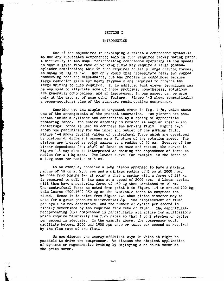
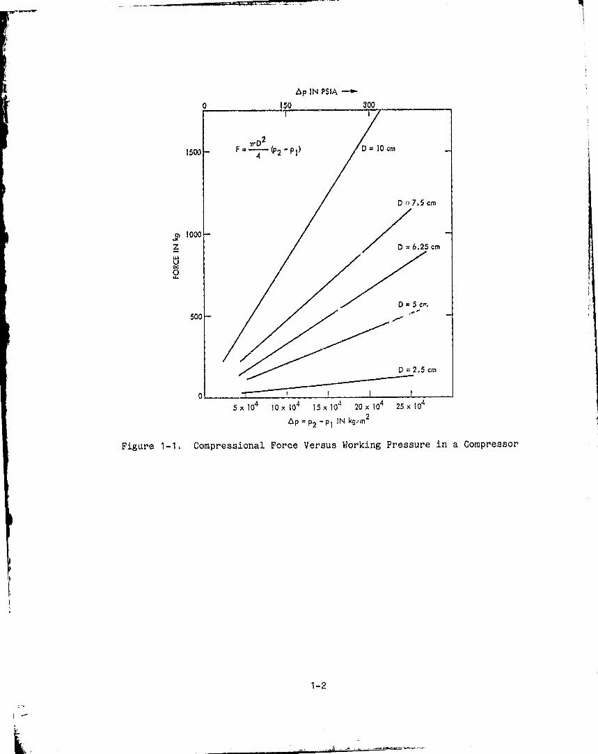
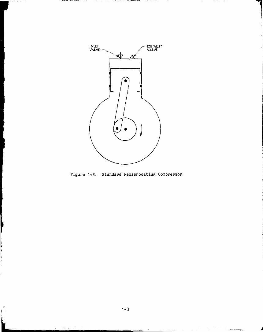
One of the objectives in developing a reliable compressor system-isto use dry lubricated components; this in turn requires slowly moving parts.A difficulty in the usual reciprocating compressor operating at low speedsis that a given flow rate of working fluid may require a large piston-cylinder combination; this in turn requires brutally large driving forces,as shown in Figure 1-1. Not only would this necessitate heavy and ruggedconnecting rods and crankshafts, but the problem is compounded becauselarge reduction gears and heavy flywheels are required to provide thelarge driving torques require;'.. It i admitted that clever techniques maybe employed to alleviate some of thew problems; nonetheless, solutionsare generally compromises, and an improvement in one aspect can be madeonly at the expense of some other feature. Figure 1-2 shows schematicallya cross-sectional view of the standard reciprocating compressor.
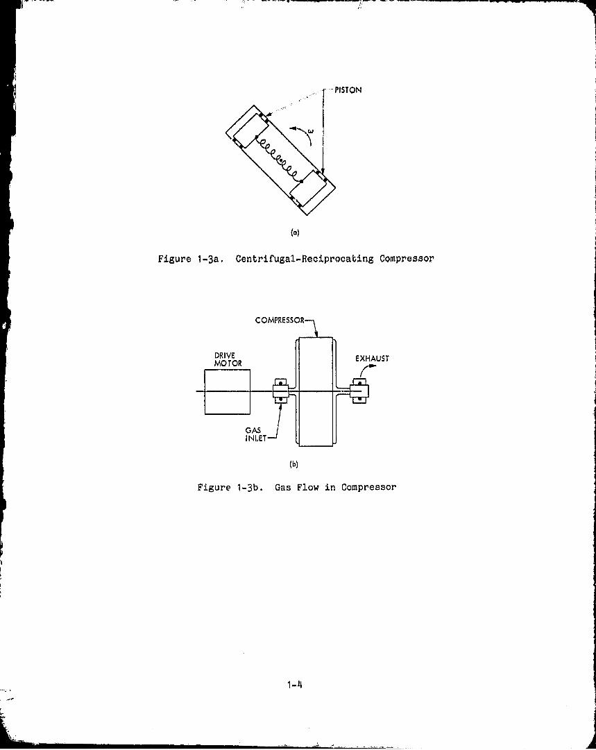
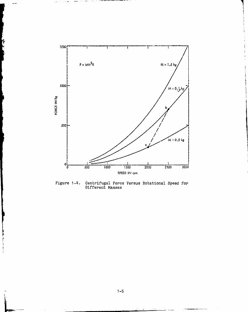
Consider now the simple arrangement shown in Fig. 1-3a, which showsone of the arrangements of the present innovation. Two pistons are con-tained inside a cylinder and constrained by a spring of appropriaterestoring force. The entire assembly is rotated at angular speed w andcentrifugal force is used to compress the working fluid. Figure 1-3bshows one possibility for the inlet and outlet of the working fluid.Figure 1-4 shows typical values of centrifugal force which are developedby pistons of different masses as a function of the rotation speed. Thepistons are treated as point masses at a radius of 10 em. Because of thelinear dependence (F = mRw? ) of force on mass and radius, the curves inFigure 1-4 may also be interpreted as showing the dependence of force or,radius for a 1-kg mass. The lowest curve, for example, is the force ona 1-kg mass for radius of 5 em.
As an example, consider a 1-kg piston arranged to have a maximumradius of 10 em at 2510 rpm and a minimum radius of 5 em at 2000 rpm.We note from Figure 1-4 at point a that a spring with a force of 225 kgis required to pull in the mass at a speed of 2000 rpm. A linear springwill then have a restoring force of 450 kg when stretched to 10 em.The centrifugal force as noted from point b in Figure 1-4 is around 700 kg;this leaves (700-450) 250 kg as the available force to compress thefluid. Hence it is noted from Figure 1-1 what piston diameter may beused for a given pressure differential A p. The displacement of fluidper cycle is now determined, and the number of cycles per second isfinally determined by the required flow rate of fluid. The, centrifugal-reciprocating (CR) compressor is particularly attractive for applicationswhich require relatively low flow rates so that 1 to 2 strokes or cyclesper second is adequate. In the example above, the compressor wouldoscillate between 2000 and 2500 rpm once or twice per second as requiredby the flow rate of the fluid.
We now discuss the energy-efficient ways in which it might bepossible to drive the compressor. We discuss the simplest applicationof dynamic or regenerative braking by employing a do shunt motor asthe prime mover.
1-1
tip IN PSIA ^—•-
1500
500
0
0 150 300
^.DxF 4 (02
>p 1 ) D» 10 em
D 7.5 cm
D = 6.25 cm
DF5cKE^ f
/ D µ 2.5 cm
i
-T 1000
zwUQW
5 x 10`1 10.
10`115 x 10' 20 x 10425 x 104
AP = P2 — P1 IN kg m2
Figure 1-1, Compressional Force Versus Working Pressure in a Compressor
1-2
I-'
INLET -EXHAUSTVALVE— .. VALVE
Figure 1-2. Standard Reciprocating Compressor
1-3
M M
^15TON
(a)
Figure 1-3a. Centrifugal,-Reciprocating Compressor
COMPRES
DRIVEI I I EXHAUSTMOTOR
GASINLET
(b)
Figure 1-3b. Gas Flow in Compressor
1-4
o^
z_WUC4
2
SPEED IN rpm
Figure 1-4. Centrifugal Force Versus Rotational Speed forDifferent Masses
1-5i
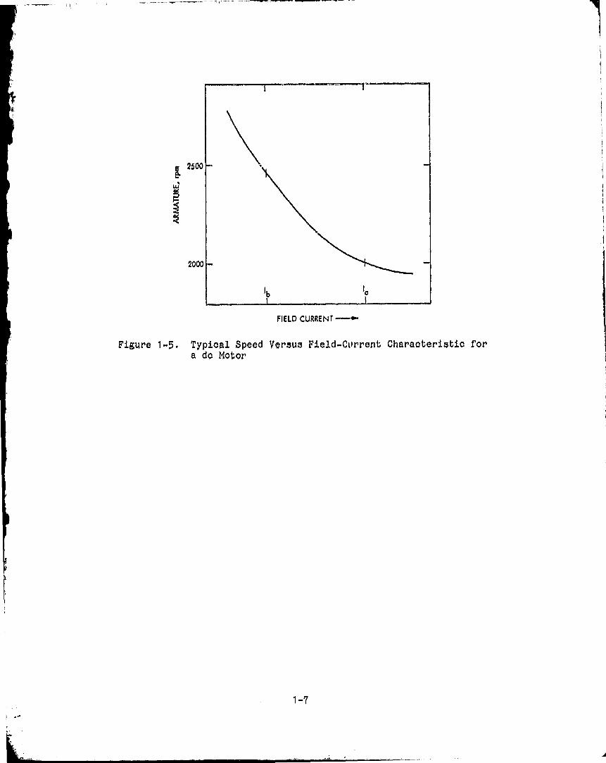
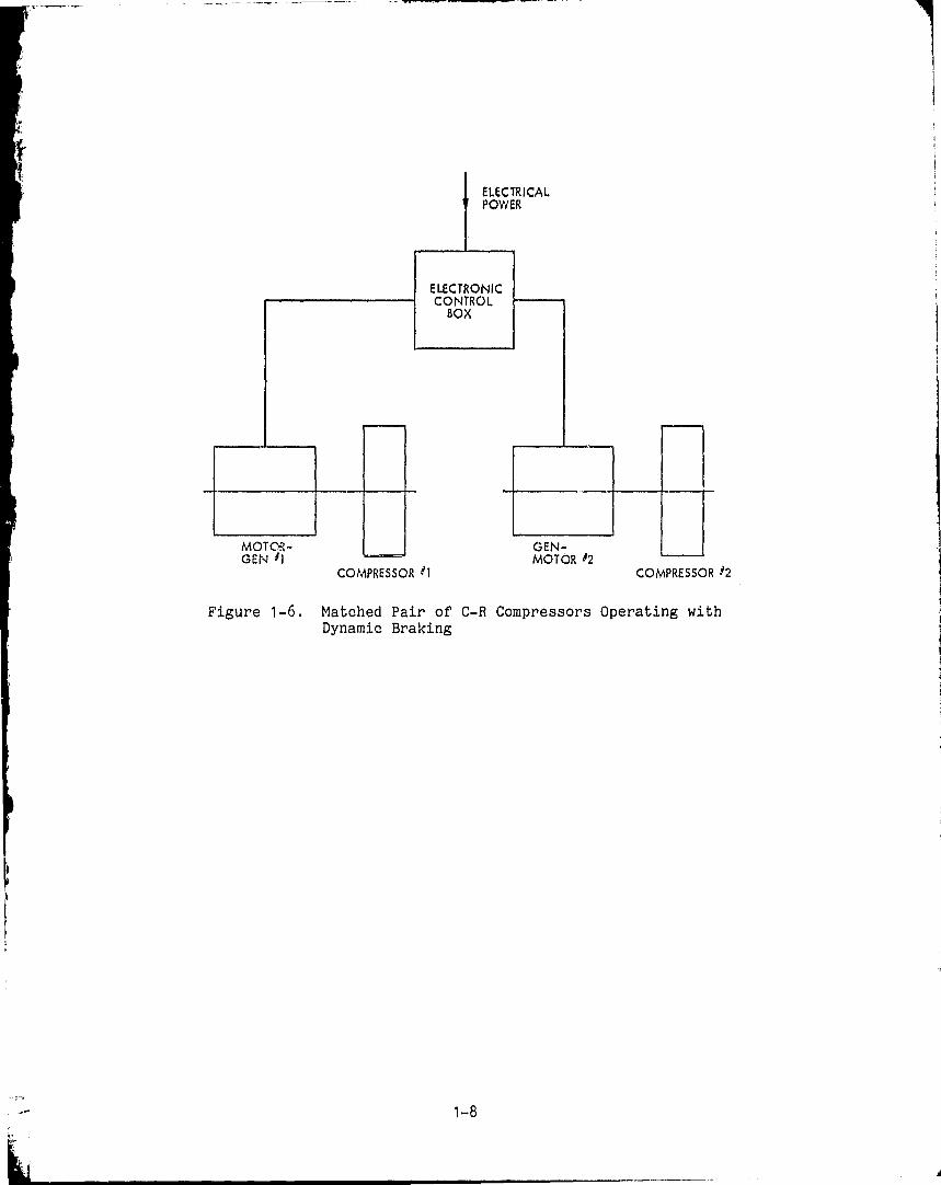
Figure 1-5 shows a typical set of charaG eristica for a shuntmotor running with fixed applied armature voltage and variable Geldcurrent. Operating ;,ants a and b have been selected to match our exampleabove It is seen tl'.-Ab by switching the field current between I a and Ibit is °1 vssible to vary the armature speed between 2000 and ?500 rpm.Furt,,,'R .iore, we know from basic electrical machinery theory that during;ex° gads of accelerations the device acts like a motor and converselylika a generator during periods of decelerations. Thus, the designof an efficient system has been made possible. An obvious way to designa good system would be to build a pair of centrifugal-reciprooatingcompressors, which may then be synchronized so that when one machine isacting as a motor the other is functioning as a generator. Figure 1-6shows schematically how this is done.
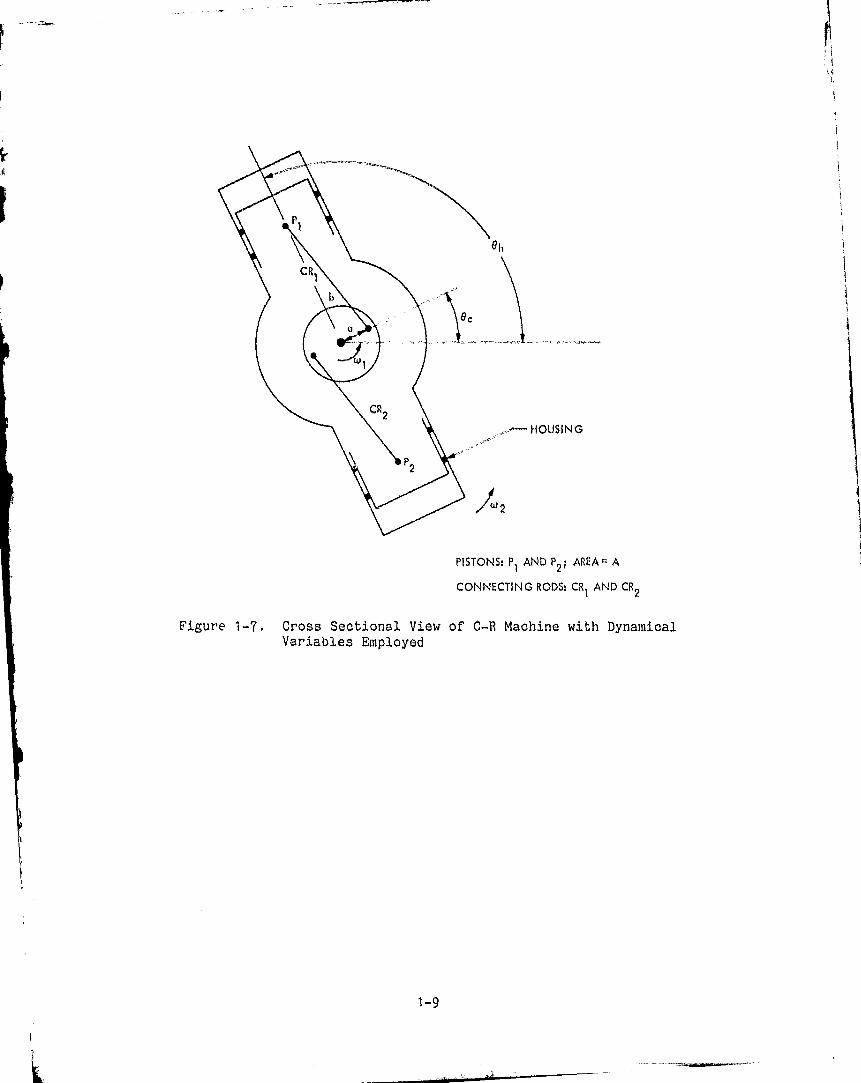
Finally, it is obvious that there are many variations of thetechnology described here; Figure 1-7 shows one such variation.Outwardly, the device looks exactly like a standard reciprocatingcompressor. The difference here is that means are provided to rotateboth the piston and cylinder assemblies so that centrifugal force playsa dominant role in compressing the working fluid. The connecting rods,for example, need not be hefty or bulky.
A disadvantage is that special sealed-bearing assemblies arerequired to communicate the working fluid to and from the compressor.However, this problem already exists in automotive oir-conditioningcompressors and has been solved.
1-6
__ ---
2000
2500
w
FIELD CURRENT ---►
Figure 1-5. Typical Speed Versus Field-Current Characteristic fora do Motor
1-7
I
3
VCIV 1 1 MVIVR "L
COMPRESSOR i t COMPRESSOR Y2
Figure 1-6. Matched Pair of C-R Compressors Operating withDynamic Braking
1-8
OUSING
PISTONS: P I AND P2 ; AREA;= A
CONNECTING RODS: CR I AND CR2
Figure 1-7. Cross Sectional View of C-R Machine with DynamicalVariables Employed
1-9
I
SECTION II
THEORY OF OPERATION
The qualitative descriptions of the centrifugal-reciprocating(C-H) machines have, up to thin point, been given in terms of theirapplications to compressing a fluid. It is noted that in a quantitativeanalysis the C-R machine should be generalized to include the possibilityof its use as a prime mover, or engine. Like most other fluid drivenmachines, the principle of reciprocity applies here and the C-R machinemay be operated as a compressor or engine.
It will become clear in the ensuing discussion that the C-R machinewill operate as an air engine, steam engine, gasoline I-C engine anddiesel I-C engine. The specific application is left for future investiga-tions.
The emphasis in this analysis shall be to study in detail thephysical mechanisms which determine the characteristics of C-R machines.Accordingly, the approximations which are made for mathematicalconvenience must be done with care so as not to obscure or alter thephysical basis of operation.
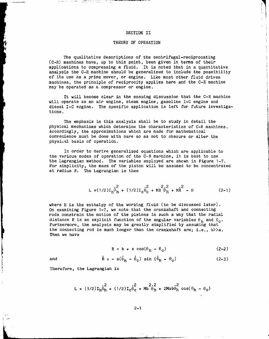
In order to derive generalized equations which are applicable tothe various modes of operation of the C-R machine, it is best to usethe Lagrangian method. The variables employed are shown in Figure 1-7.For simplicity, the mass of the piston will be assumed to be concentratedat radius R. The Lagrangian is then
L =(1/2)I hOh + ( 1/2)I c ec + MR2e h + MR2 - H (2-1)
where H is the enthalpy of the working fluid (to be discussed later).On examining Figure 1 -7, we note that the crankshaft and connectingrods constrain the motion of the pistons in such a way that the radialdistance R is an explicit function of the angular variables O h and ec.Furthermore, the analysis may be greatly simplified by assuming thatthe connecting rod is much longer than the crankshaft arm; i.e., b>>a.Then we have
R = b + a cos (e h - e c ) (2-2)
and R = - a(e h - ec) sin ( Oh - ec ) (2-3)
Therefore, the Lagrangian is
2 2 2.2 2L = (1/2)Iheh + (1/2)Icec + Mb eh + 2Mabeh cos(eh - ec)
2-1
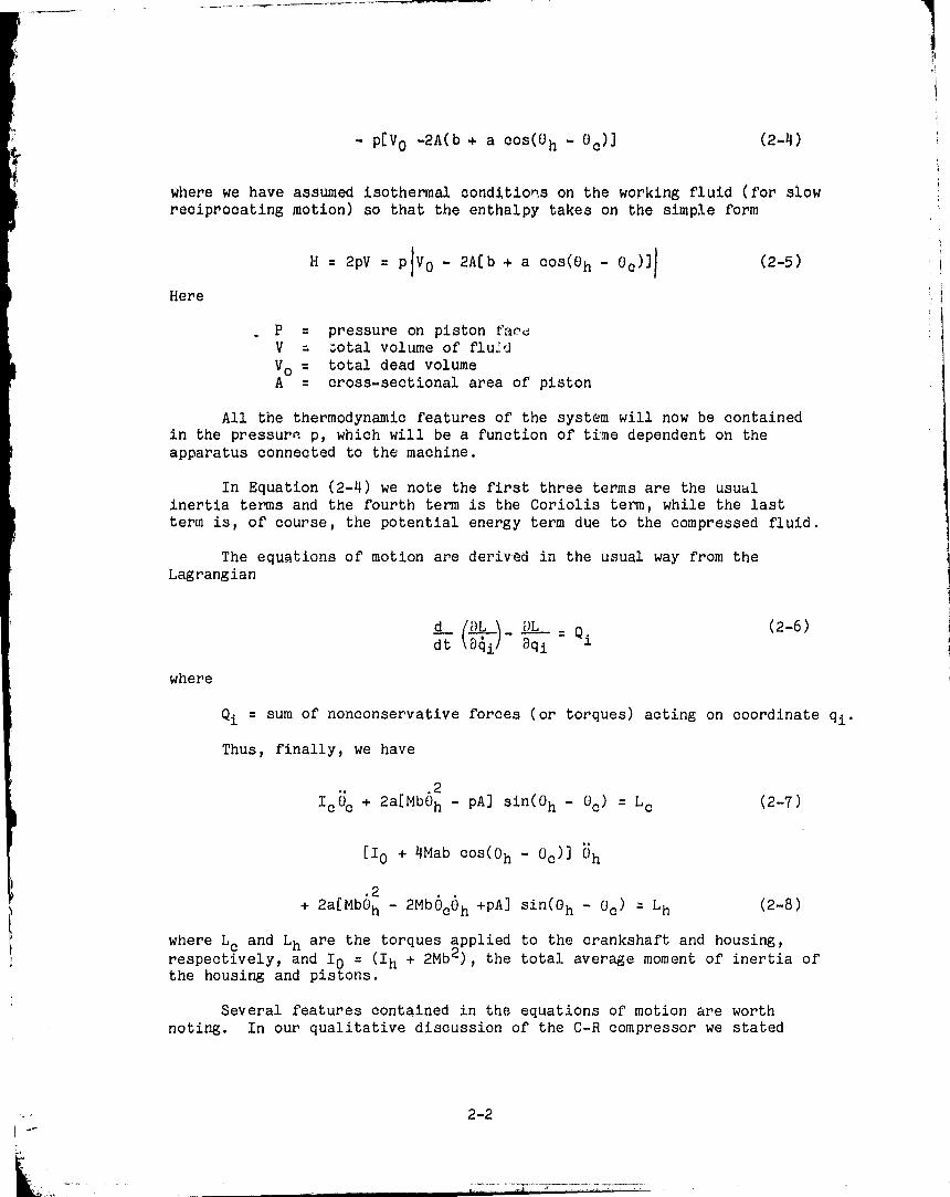
- p[V C -2A(b + a cos(O h - Cc)]
( 2 -4)
where we have assumed isothermal conditions on the working fluid (for slowreciprocating motion) so that the enthalpy takes on the simple form
H = 2pV = pIV O - 2A[b + a cos(O h - Oo)11 (2-5)
Here
P = pressure on piston favttV = total volume of flu.:,,Vo = total dead volumeA - cross-sectional area of piston
All the thermodynamic features of the system will now be containedin the pressure p, which will be a function of time dependent on theapparatus connected to the machine.
In Equation (2-4) we note the first three terms are the usualinertia terms and the fourth term is the Coriolis term, while the lastterm is, of course, the potential energy term due to the compressed fluid.
The equations of motion are derived in the usual way from theLagrangian
(2-6)d (/8L _ DL Qdt 10gi@qii
where
Qi = sum of nonconservative forces (or torques) acting on coordinate qi.
Thus, finally, we have
I c Uc + 2a[Mb62 - pAl sin(O h - Uc ) = L c(2-7)
[Io + 4Mab cos(Oh - O c )l Uh
2+ 2a[MbOh - 2Mb pc6 h +pAl sin(O h - Oc) = L h(2-8)
where Lc and Lh are the torques applied to the crankshaft and housing,respectively, and 1 0 = (I h + 2Mb2 ), the total average moment of inertia ofthe housing and pistons.
Several features contained in the equations of motion are worthnoting. In our qualitative discussion of the C-R compressor we stated
2-2
.2that the centrifugal force MbOh must be larger than the force due to thefluid pA in order for there to be motion of the pistons.
In Equation (2-7) it is apparent that there can be no relative motionbetween crankshaft and housing until centrifugal force balances the fluidforce, i.e. until the quantity in brackets vanishes. Then there shall beacoelerati,on 0,*0 to permit motion of the piston relative to the housing.In Equation (2-8) the same criterion is contained in the second bracketedquantity. This is apparent ;,hen it is realized that (3 cUh at the thresh-old of balanced forces.
The first bracketed quantity in Equation (2-8) is simply the totalinstantaneous moment of inertia of housing and pistons, and shows how thisquantity is modulated by the motion of the pistons. The analogy toparametrically excited electrical networks wherein self-inductance ismodulated is to be noted.
The equations of motion (2=j) and (2-8) are coupled nonlinear equationsand cannot be linearized in the usual way since the nonlinear mechanisms areessential to the operation of the machine. On the other hand, the nonlin-earities in (2-7) and (2-8) prohibit us from finding general solutions tothese equations. What can be done is to find special solutions to theequations and the conditions under which the assumed solutions are valid,
In particular, we shall treat two special cases: (1) a periodictorque is applied to the crankshaft with no external torque applied to thehousing; (2) the crankshaft and housing are separately driven at slightlydifferent but constant speeds.
A. CASE (1): PERIODIC TORQUE APPLIED TO CRANKSHAFT
We assume, in spite of the nonlinear equations of motions, that ourintuitive feeling is correct about a periodic torque producing a periodicresponse in the C-R machine. We start by assuming a simple periodicmotion and calculate the torque required to produce it.
Referring to Figure 1-7, it can be shown that an acceptable form forthe angular displacements as a function of time is given by
(+ h = wo t + 0 TsinAt + (1 - cos At)
tic = wot + 0 sinOt - X1(1 - cos At)
(2-9)
(2-10)
On taking the time derivatives, we have
O h = wo + acosdt + L' At
(2-11)
2-3
0 0 = wo + aoosAt - E Asin At
(2-12)
whence we see that wo is the mean angular velocity, a is amplitude of
periodic angular velocity and A is the rate at which the angular velocityis modulated (also equal to 2Trtimes the strokes per second).
In these equations we assume that the crankshaft makes a full 180deg excursion when the pistons moves from TDC (top dead center) to BDC(bottom dead center). The coefficients of the last terms in Equations(2-9) and (2-10) were chosen to fulfill this assumption. To simplifythis analysis we also assume that there is no dwell in any positionof the pistons. We also need the expansions for
sin(0h - 00 ) = sin 2 (1 - cosAt)
= J0(2 1 + 2J 2(2) cos 2At + ,.. (2-13)
and
cos(Oh - 0 0 ) = 2J1(2) sin At + 2J 3(2 1 sin 3At + ... (2-14)
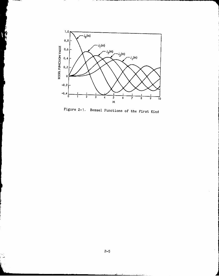
where the Jn 's are nth order Bessel functions of the first kind. Thesefunctions are shown in Fig. 2-1. Thus substituting all the foregoingquantities into the equations of motion we have, from (2-7),
Lc = a j ( 4Mbwo - 2p oA sin 0 ) cos At
+ (MbnAwo -2poA cos 0) sin At1 JO 2 + 2J 2 2 cos 2At (2-15)
and from 2-8 (neglecting higher harmonics)
rrI0A24 -J0 (21 (2ciMbwo - p0A sin 0) cos At
nAMbwO
I0 aA Jo (2 ) 2 + p 0A cos 0 sin At = Lh = 0 (2-16)
2-4
i,("
0,E
wa 0,E
o 0.4
G
m 0.2Jw
w 0m
-0.2
-0.a
` a a a 7 8 9 10M
Figure 2-1. Bessel Functions of the First Kind
2-5
where we have used
p Po + po sin (At + (r ) (2-17)
and have neglected, for simplicity, the term due to the modulation ofmoment of inertia. As discussed in the introduction, the average gaspressure Po = Mbwo2 , the average centrifugal force for the dynamicallybalanced mode of operation.
Equation (2-15) gives the torque required to produce the assumedmotion, and Equation (2-16) gives the dynamical constraints on a and Aas a function of design parameters such as M, To, wo, and po. Theequations of motion are inherently nonlinear, and we are allowed theassumed motions provided we can find real solutions (from Equation2-16) for a and A from
Trx0A2 - JO(2) [8aMbwo - 4poA sin 0^ = 0 (2-18)
2I0a A-JOW 11T
Mbw^.+ 2p oA cos 0' = 0 (2-19)
The crankshaft power required is given by
P.,, = Lc x Uc = L c x (woA+ a cos At - 4 Asin At)r
P` = a 1(4Mbwo a -2poA sin 0) cos At
+ (MbTrAwo -2poA cos 0) sin Atl J0(z x (w0 + a cos At -r lAsin At) (2-20)
It can be shown very easily that the constant part of (2-20) is given by:
Pc (constant) = a 1
(4Mbwo cL -2p oA sin 0) a
- (MbTrAwO -2p oA cos 0) (4) A JO(2)
A little reflection shows that the time average value of P o may bepositive (compressor) or negative (engine) depending on the phaseangle of the pressure wave. This ought not to be too surprising since
and
or
2-6
the conventional air engine is simply a special oase: 6 h = p of theC-R engine.
B. CASE (2): CRANKSHAFT AND HOUSING DRIVEN AT SLIGHTLY DIFFERENTBUT CONSTANT SPEEDS
This mode of operation, which may also be called the positivedisplacement mode, is primarily of academic interest since reducing theforces by a factor of 2 may not be appreciated by the designer. However,the equations reduce to such simple form that it is worthwhile digressingfor a moment.
In Equations (2-7) and (2-8) we let
O h =w h =wo +2
and
OOc = we w° 2
with
Oh= 6c=0
Then
Lc = 2a[Mb(wo2 + w cA) - PoA - poA sin(At + 0 )] x sin At (2-21)
Again we let Mbwo2 = PoA. Then
Lo = 2a[Mbwo A poA sin(At + 0)] sin At (2-22)
Similarly
Lh = 2a[Mbwo A+ poA sin(At + 0 )] sin At
(2-23)
2-7
Thus the total shaft power is
p = Lobo + Lh6h
(- apo A cos Q + 2aMb A sin A t
+ apoA cos 2At)(wo -)
+ [apoA oos U + 2aMbA sin At
- apoA cos (2At + 0))(w o + 2) (2-24)
or
2P = apoAO cos 0 + 2aMbAwo sin At - ap oAA cos(20t + p ) (2-25)
Thus, the machine operates as an engine or compressor by properchoice of 0.
2-8
SECTION III
CONCLUSIONS
The C-R machine may be regarded as a velocity transformationdevice. When used as a compressor it produces slow reciprocatingmotion from high-speed rotational motion. In the conventionalreciprocating compressor a large speed reduction gearbox andhefty crankshaft and connecting rods would be required. Evenif the size and weight of the compressor did not matter, thereliability of gearboxes leaves much to be desired. Hence, theprincipal advantage of the C-R compressor is in the potentialityfor small, lightweight compressors with high reliability.
When used as an internal combustion engine the C-R machinetransforms slow reciprocating motion into high rotational speeds.The advantage here is that the engine can operate in a mode whichcomes closer to the Carnot cycle than in the standard configuration.In fact, the hypothetical Carnot cycle could really be executedin textbook fashion because the reciprocating motion may be madeas slow as desired.
The standard reciprocating air engine may be regarded as aspecial case of the centrifugal-reciprocating machine. The performancecharacteristics of the C•h machine, however, are considerably differentfrom the standard engix.=a because of the nonlinearities introducedinto the equations of v.);.icn by the rotating housing. It has beenshown that the nonlinear,Lies tend to limit the C-R machine tocertain ranges of the parameters such as speed, working pressure,etc. However, there are many applications, such as electric powergeneration, where the restriction to a constant speed is not aproblem.
Only two special cases have been considered in this study; theextension to other cases is expected to be straightforward.
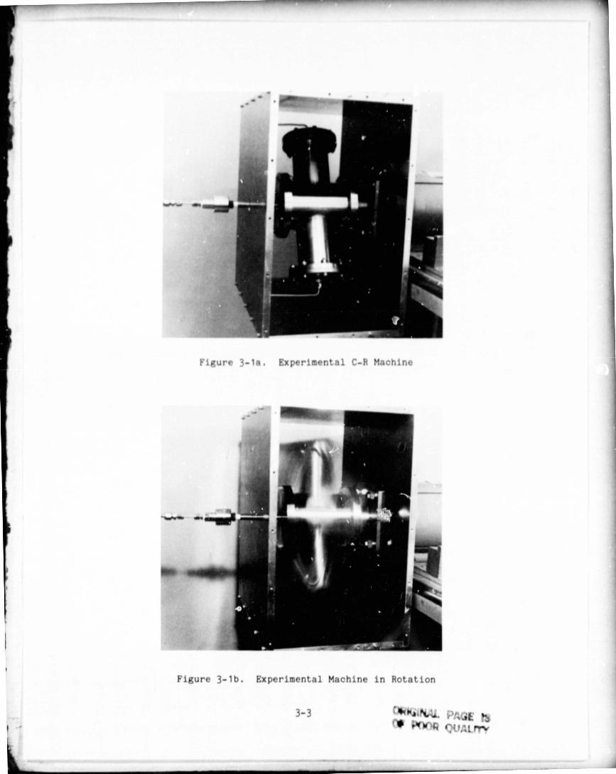
An experimental machine shown in Figures 3-1a and 3-1b wasconstructed to demonstrate the fundamental concepts of this paper.The experimental model was designed to demonstrate feasibilityof the concepts, and no attempt was made to compare quantitativeperformance with theory. The model was intended to be operablewith the CTI 350 Cryodyne and was sized accordingly as shown inTable 3-1.
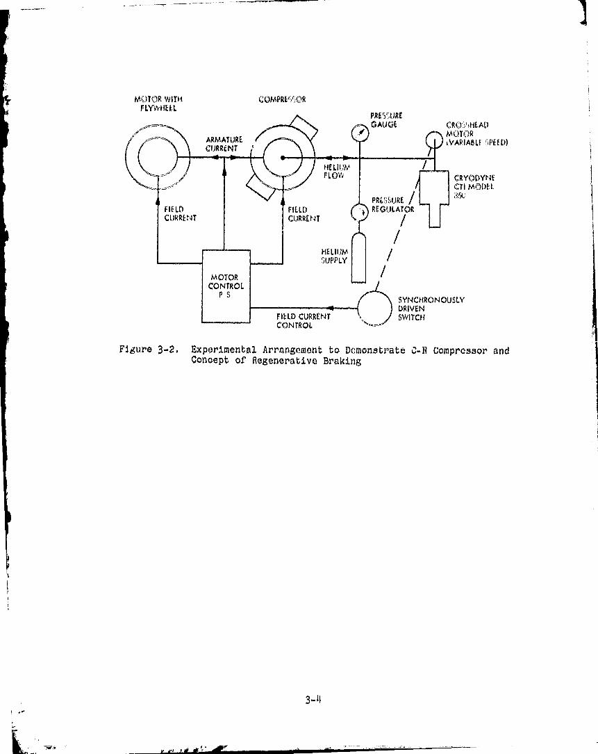
The large weight of the assembly made it difficult to obtainreciprocating speeds larger than 20 per minute, but the slow speedsimplified the seal problem by permitting the use of lubricatedrubber 11 0" rings for these tests. Only one test compressor wasbuilt, and it was necessary to use a flywheel on a second motor todemonstrate the regenerative braking concept as shown in Figure 3-2.
3-1

Ilia preliminary test results were adequate to demonstrate thebasic concepts of this paper. The maximum centrifugal force developedwas 770 kgm, and the ford due to the compressed gas was 710 kgm.The pressure ratio of 32 is encouraging, especially when comparedwith Vuilleumier systems. The slow reciprocating speeds achieved wasdisappointing, but not altogether unexpected since the structure wasso massive. The important parameter which needs optimization is theratio of piston mass to total structure mass. This ratio should bemade as large as possible.
3-2
as
WAW
rr
Figure 3-18, Experimental C-R Machine
Figure 3-1b. Experimental Machine in Rotation
3-3 ^Ki1NL•ti, PAGE N
r 'a QUAL,rry
MOTOR WITH COMPREI')r(--)RFLYi*,rkftl;
PRF'UREGAUGE C R 0Y) HE AD
MOTORi.VAPIAOLF ")PEEW
CRYODYNICTI MODEt
3 ^k
SYNCHRONOUSLYDRIVENSWITCH
1.U1111KV6
Figure 3-2. Experimental Arrangement to DC'monstorate C-R Compressor andConcept of Regenerative Braking,
3-4
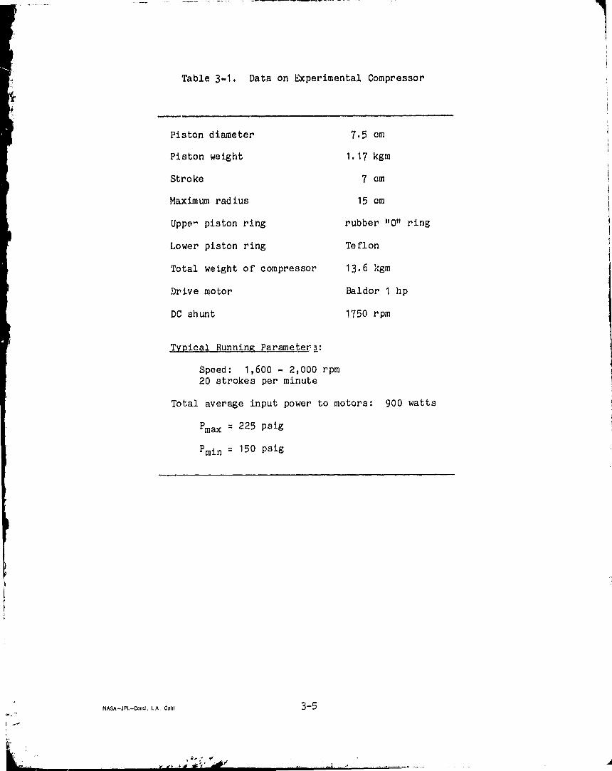
Table 3-1. Data on Experimental Compressor
Piston diameter 7.5 cm
Piston weight 1.17 kgm
Stroke 7 cm
Maximum radius 15 cm
Upper piston ring rubber 11 0 11 ring,
Lower piston ring Teflon
Total weight of compressor 13.6 kgm
Drive motor Baldor 1 hp
DC shunt 1750 rpm
Typical Running Parame ter 1:
Speed: 1,600 - 2,000 rpm20 strokes per minute
Total average input power to motors: 900 watts
Pmax = 225 psig
Pmin = 150 psig
3-5NASA—JPL—Coml , L A, Calif