![[MC-CSDL]: Conceptual Schema Definition File Format · 8 / 141 [MC-CSDL] — v20130722 Conceptual Schema Definition File Format Copyright © 2013 Microsoft Corporation. Release: Monday,](https://static.fdocuments.us/doc/165x107/5e71b48b783af846701a85f7/mc-csdl-conceptual-schema-definition-file-format-8-141-mc-csdl-a-v20130722.jpg)
THIS DOCUMENT HAS BEEN REPRODUCED FROM … · THIS DOCUMENT HAS BEEN REPRODUCED FROM MICROFICHE....
69
N O T I C E THIS DOCUMENT HAS BEEN REPRODUCED FROM MICROFICHE. ALTHOUGH IT IS RECOGNIZED THAT CERTAIN PORTIONS ARE ILLEGIBLE, IT IS BEING RELEASED IN THE INTEREST OF MAKING AVAILABLE AS MUCH INFORMATION AS POSSIBLE https://ntrs.nasa.gov/search.jsp?R=19820016548 2018-06-06T01:31:10+00:00Z
Transcript of THIS DOCUMENT HAS BEEN REPRODUCED FROM … · THIS DOCUMENT HAS BEEN REPRODUCED FROM MICROFICHE....

N O T I C E
THIS DOCUMENT HAS BEEN REPRODUCED FROM MICROFICHE. ALTHOUGH IT IS RECOGNIZED THAT
CERTAIN PORTIONS ARE ILLEGIBLE, IT IS BEING RELEASED IN THE INTEREST OF MAKING AVAILABLE AS MUCH
INFORMATION AS POSSIBLE
https://ntrs.nasa.gov/search.jsp?R=19820016548 2018-06-06T01:31:10+00:00Z

" ,
DOE/NASA/0817-1 NASA CR-165168 Draper Report R-1489
DEVELOPMENT OF
r , I
A DUAL-FIELD HETEROPOLAR POWER CON\fERTER
David B. Eisenhaure Bruce G. Johnson Tim E. Bliamptis Emery st. George
P.ugust 1981
Prepared for NATIONAL AERONAUTICS AND SPACE ADMINISTRATION Lewis Research Center Under Contract NAS3-20817
for
U.S. DEPARTMENT OF ENERGY Conservation and Renewable Energy Office of Vehicle and Engine R&D
(NASA-CR-16516B) PEVELOPMEN~ OF A NB2-24424 DUAL-FIELD H.BTEhOfUPLAR fGWE& CCNVEii~Eli: (Department of Ene,cgy) 68 p HC A04/111F A01
CSCL 10B Unclds G3/33 09935

~L. t'
. . ' :.. i \~ ." --- ~. j -II...·. " . . ~.' ~ "
TECHNICAL REPORT STANDARD TITLE PAGE
2. Government Acceulon No. -3. Recipient's Catai~!! No. 1. Report No.
NASA CR-165168 h--.,:.~:-:::rT.:'[~-:------'-------------+I!'""'1!=~=~---:"------I 4. Title and :>ubtltle 5. Report Date
DEVELOPMENT OF A DUAL-FIELD HETEROPOLAR August 1981 POWER CONVERTER 6. Performing Organization Code
7. Author(s) D.EisenJlaure, B.Johnson, T.B1iamptis, E.St.George
9. Performing Organization Name and Addreu
Charles Stark Draper Laboratory Inc. 555 Technology Square Cambridge, Mass. 02139
~~-~~----~-~~~-----------------~ 12. Sponsoring Agency Name and Address U.S. Department of Energy Conservation and Renewable Energy Office of Vehicle and Engine R&D Washington, D.C. 20585
15. Supplementary Notes
8. Performing Organization Report No. R-1489
10. Work Unit No.
11. Contract or Grant No.
NAS3-20817 13. Type of Report and Period Covered
Contractor Report
14. Sponsoring Agency Code
DOE/NASA 0817-1
Final Report. Prepared under Interagency Agreement DE-AIOl-77CS1044 Project Manager, E. McBrien, Electric Vehicle Components Section, NASA Lewis Research Center, Cleveland,'Ohio 44135
16. Absfract
This report deSCI"ibes the design and test of a 400 Wqtt, dual phase, dual rotor, field modulr;.ed inductor alternator. The system is designed for use as a flywheel to AC utility line or flywheel to DC bus (electric vehicle) power converter. The machine is unique in that it uses dual rotors and separately controlled fields to produce output current and voltage which are in phase with each other. Having the voltage and current ~n phase allows the power electronics to be madeof simple low cost components.
Based on analytical predictions and experiwental tesults, development of a complete 22 kilowatt (30 Hp) power conversion system is recommended. This system would include power electronics and controls and would replace the inductor alternator with an improved electromagnetic conversion system.
17. Key Words Suggested by Author ""l1'8. Distribution Statement .
Field Modulation; Power Conversion; 1 Unclassified - unlimited Variable Speed to Constant Frequency; STAR Category 33 Frequency Converter; Inductor DOE Category UC-96 Alternator; Flywheel Electric Vehicle
19. Security Classif. (of thill report) 20. Security ClaSloif. (of this page) 21. No. of Pages 22. Price
Unclassified. Uncl assifi ed. •

j
~
..
DEVELOPMENT OF A DUAL-FIELD HETEROPOLAR POWER CONVERTER
David B. Eisenhaure Bruce G. Johnson Tim E. BliampHs Emerv c~ ~;;'v- .. rU:3 ~, .,. vl. ~'-' ,~...,.
August,981
Prepared for
DOE/NASA/0817-1 NASA CR-165168 Draper Report R-1489
NATIONAL AERONAUTICS AND SPACE ADMINISTRATION Lewis Research Center Under 01 mtract I\lA83-20817
for U.S. DEPARTMENT OF ENERGY Conservation and Renewable Energy Office of Vehicle ami Engine R&D Washington,. D.C. 20585 Under Interagency Agreement DE .. A101-77C81044

1.
2 •
3 .
PRECEDING PAGE BLANK NOT FILM.ED
TABLE OF CONTENTS
page
. . . . . . . . . . . . . . • • • • • • SUMMARY • • •
INTRODUCTION . . . • • • • • • • • !It •
1
3
Back ground • . , . • • • • . • • • • • • • • • .• 3 History of the Program. . • • • • • • . • . . •• 7 Program Overview • • • • • • •. ••• • • 8 System Requirements . • . • . . • • • •• 9
Original System Requirements ••••••.•• 9 Original System Performance Specifications. 9 Original System Component Specifications .. 10
Modified System Requirements ••••••••• 11 Modified System Performance Specifications. 11 Modified System Component Specifications •• 12
INDUCTOR ALTERNATOR DESCRIPTION •. · • • 13
Vdriable Reluctance .•. · , . . . . 13 o u a 1 R 0 to r • •• ., • • • · . . . . . 16 Dual Phase . . . . .• .••. · . . . . . 21 Field t1odulation • . • . • •. • .• · . . . . . 21 Controll er ••.•..•.•... • • • 4 • • 23
4. CSDL INDUCTOR ALTERNATOR DESIGN . . • • • 28
5 •
~1echanical Design Wi nd; n,~s Des; gn Magnetic Design Controll~r v~sign
• • • !It • • • • • •
~.~.". ,.. '.. . . .
CSDL INDUCTOR ALTERNATOR PERFORMANCE • •
• • • • • • 28 . . . . . 31
• • • 33 • • 39
· ~ . . • • 42
Test Set-Up ...••••..••••.••••• 42 Generator Performance . . •. • •..•• 42 Motor Performance . • . • . . • .. •• • 52 Demonstration of Frequency Conversion • ¢ •••• 58
6. CONCLUSIONS AND RECOMMENDATIONS . . . 61
. 61 • • • 63
Conclusions Recommendations
7. BIBLIOGRAPHY . . .
vii
• • f· •
~ . . . . • 64

1. SUMMARY
This report describes the design and test of a 400' watt inductor a1ternator. The inductor alternator was designed and tested by the Charles Stark Draper Laboratory, Inc. (CSDL) under contract to the National Aeronautics and Space Administration~ Lewis Research Center (NASA/LeRC). This research advances the development of flywheel to AC utiiity line and flywheel to DC bus (electric vehicle) power conversion systems.
In its final conf'fguration, the inductor alternator consists of ,a dual phase, dual rotor, field modul~ted
el ectromechani cal system wi th associ ated power el ec .. tronics, test bed, and controller. The use of a
variable reluctance machine (inductor alternator) comb,tned with field modulation allows the system to
coupl e hi gh and vari abl e shaft speeds (5,000-10,000 rpm) with fixed frequency electrical networks. Also, with dual rotors and separately controlled fields, the output voltage and current are in phase with each other. This allows the power electronics to be made of simple, low cost components. With no filtering, output ripple of 6% was achieved over the 2 to 1 speed range. These advantages are somewhat offset by the basel ine system's relatively low power density and efficiency.
An analytical model of the inductor alternator was developed. The agreement between the model's predi ctions and experimental measurements is quite good. The model predicts that the efficiency could be raised by

2
increasing the winding volume. The use of higher shaft speeds and a less conservative design could increase the power density by a factor of 30.
Development of a complete 22 kilowatt (30 HP) power conversion system for electric vehicles is recommended. Thi s system woul d i ncl ude power el ectroni cs and controls and would replace the inductor alternator with an improved electromagnetic conversion system.

2. INTRODUCTION
2.1 BACKGROUND
A need exists for systems which store electt'ical util i ty power duri ng off-peak hours. Flywheel energy storage is a promising system that can meet this need. Flywheels are reliable, long lasting, and inexpensive and can potentially store enetgy efficiently at high energy denlities.
In an effort to improve perfotmance at the interface between the flY\l/heel and the utility grid, The Charles Stark Draper Laboratory, Inc. (CSDL) studied the conceptual design and development of advanced suspension and energy conversion sUbsystems. These studies were sponsored by the National Science Foundation~ NSF Grant AER75-18813, and were completed in November 1977 (1 ) • I nit i all y d ire c ted tow a r d u til i tyl 0 a d 1 eve 'l i n g , the studies were later expanded toward applications in electric vehicles, mass transit, and solar or wind energy generation systems.
The function of the flywheel energy storage system in a utility grid is leveling the electrical load in the generation/dist'1hution system. Thus the flywheel will stote energy Whbl'; electrical demand is less than ganerati on and provi de energy when demand is greater than generation. To reduce the reactive power in the grid, the system should also independently provide power factor correction. With these system objectives
3

ill vie\'-I, a detailed set of desired ch~racteristics for an energy conversion system which interfaces a flywheel shaft and an AC line WaS formulated at Draper. The system should:
1. Handle independently-controlled amounts of real and reactive power (power factor corr~ction).
2. Provide motor/~enerator operation in a single electromechanical unit.
3. Provide controlled output frequency, voltage and power from a variable speed shaft.
4. Provide stand-alone or grid-coupled capab11ty.
5~ Provide waveforms with low harmonic content after minimal filtering.
6. Provide high efficiency and high power density at low <;ost.
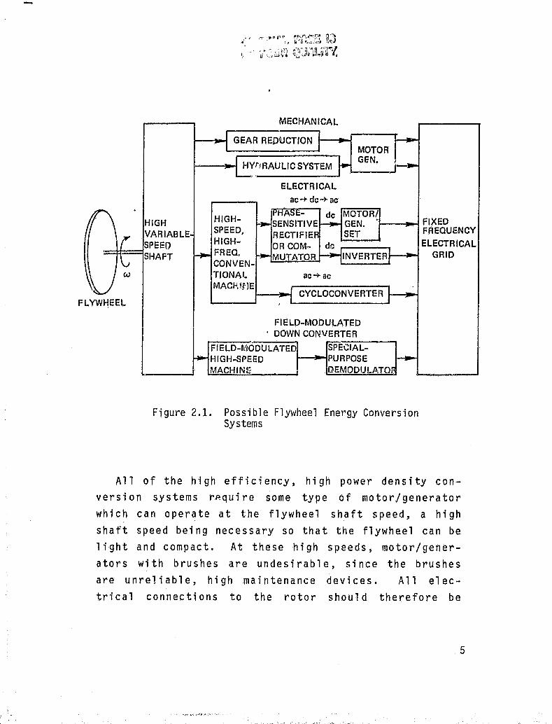
The different types of energy converters which can match the high, variable shaft speed (5,000-10,000 rpm) of a flywheel to a fixed frequency electrical grid are shown schematically in Figure 2-1. The suitability of these various conversion systems for flywheel appl ications was analyzed; the rt£;sults are shown in Tabl~
2-1, and are summarized below. Details of the analysis can be found in Reference (1).
4
I. V
MECHANICAL
GEAR REDUCTION t--..""i MOTOR GI:N.
HIGH VARIABLE
HIGHSPEED, HIGHFREQ, CONVENTIONAl_ MACk~flE
r--~ FIXED FREQUENCY
=1:t=~SPEED SHAFT
FLYWI1EEL
ac-+ ac
CYCLOCONVERTER .. -......,
FIELD-MOOULATED . DOWN CONVERTER
FIELD-~!IODULATED SPECIAL-HIGH-SPEED J--~PURPOSE
,, ___ --JJ MACHINE DEMODlJlATO.
Figure 2.1. Possible Flywheel Energy Conversion Systems
ELECTRICAL GRID
All of the high efficiency, high power density conversion systems rp.quire some type of motor/generator which can operate at the flywheel shaft speed, a high shaft speed being necessary so that the flywheel can be light and compact. At these high speeds, motor/generators with brushes are undesirable, since the brushes are unreliable, high maintenance devices. All electrical connections to the rotor should therefore be
5
,!
( !
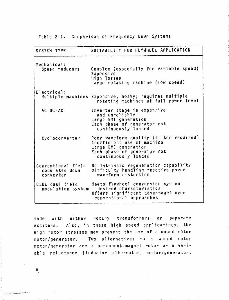
Table 2-1. Comparison of Frequency Down Systems
SYSTEM TYPE
Mechanical: Speed reducers
Electrical:
SUITABILITY FOR FLYWHEEL APPLICATION
Complex (especially for variable speed) Expensive High losses Large rotating machine (low speed)
Multiple machines Expensive, heavy; requires multiple rotating machines at full power level
AC-DC-AC
Cycloconverter
Conventional field modulated down converter
CSDL dual field modulation system
Inverter stage is expen~ive and unreliable
Large EMI generation Each phase of generator nat
L~ntinuously loaded
Poor waveform quality (filter required) Inefficient use of machine Large EM! generation Each phase of genera'~,Jr not
continuously loaded
No intrinsic regeneration capability Difficulty handling reactive power
waveform distortion
Meets flywheel conversion system desired characteristics
Offers significant advantages over conventional approaches
made with either rotary transformers or separate exciters. Also, in these high speed applications, the high rotor stresses may prevent the use of a wound rotor motor/generator. Two alternatives td a wound rotor motor/generator are a permanent-magnet rotor or a variable reluctance (inductor alternator) motor/generator.
6
I
" '(
; " , ,

A permanent magnet m~tor/generator has two significant problems when used in this application, First, since the magnetic field is a constant, continuous losses are incurred in the stator iron even when the motor/generator is coasting. This pr~~lem can be eliminated by suspending the stator coils and rotating the back iron with the rotor. However, the elimination .of this problem requires a complex, unconventional design. Second, since the generated voltage ;s proportional to speed and must equal the linc voltage at minimu'.'l s~~ed, the generated voltage will be at least twice the line Yoltage at maximum speed (twice minimum speed). Therefol~e, a "J,,~ri abl e vol tage power converter stage is required. However, the permanent magnet machine generally has lower machine inductance than an e qui V (',1 en two u n d rot 0 r mac h i n e • Sin /~ e t hi s can be an advantage in semiconductor switched conversion systems. the permanent magnet machine remains a candidate, particularly when a DC output voltage is desired.
The variable reluctance machine (indti~tQr a1ternator) is an attractive choice for the frequency down·· converter. The probl ems of hi gh speed brushes and wound rotor str-sss 1 i mi ts are avoi ded, s1 nce all the windings are on the stator. Also, field control, i ncl udi ng modul at; on, is poss; bl e wi th the inductor
alternator.
2.2 HISTORY OF THE PROGRAM
The National Areonautics and Space Administration, Lewis Research Center, (NASA/LeRC), contracted with CSDL to des; gn, fabri cate, and test a flywheel energy
7

conversion system based on the NSF sponsored studies. The NASA/LeRC program was originally aimed at developing a f1ywhee1-to-AC line interface, with the system impl emented as a bi di recti onal frequency converter. A dual rutor, field modulated inductor alternator was designed and partially fabricated.
At this point in the program, the system requirements were altered. A change in priorities at NASA/LeRC resulted in a contract modificiJ,tion calling for a shift in emphasis from the AC line interface to an electric vehicle (EV) application. In this applicat'ion, tho flywheel would be coupled with a bat.tery; current surges would then be absorbed by the flywhep.l. To demonstrate the concept, the inductor alternator was therefore completed and t~sted as a DC-input/DC-output device. h"",'/ever, it was not anticipated that this particular CSOL inductor alternator would prove to be the optimum device for this application.
2.3 PROGRAM OVERVIEW
The system which was consists of a 400 watt
actually des; gned and buil t breadboard conversion
which serves both as a proof of concept and as a dation upon which further work can be built.
unit, foun
The design was based on the original requirements for an AC line interface as listed in Section 2.4.1. Components based on this design were fabricated. Prior to assembly, the requirements were changed to the DC line interface, as given in Section 2.4.2. The machine was accordingly wound, assembled and tested to meet these iatter requirements.
8
, i r

The conversion unit was tested as a flywheel to DC bus motor'/gencrator. Power output, efficiency, and vol tage ri ppl e over a 5000-10000 RPM speed range were measured. Also, its use as a flywheel to AC line generator, as originally specified, was demonstrated. These experimental results were compared with predictions of the analytical models in order to validate these models. Recommendations of areas for further study were based on the test results and analytical
models.
2.4 SYSTEM REQUIREMENTS
2.4.1 Original Systel)1 R.!Lqu;rements
Contra,ct No. NAS3-20817, dated July 13, 1978, from the National Aeronautics and Space Administration, Lewis Research Center, originally called for the design and test of a bidirectional power conversion system. Employing an inductor alternator and a solid-state switching network, the system was to operate from a 60 Hz line as a motor, and drive a 60 Hz load as a generator. The following system and component specifications were prov;~ed:
2.4.1.1 Original System Performance Specifications
Generator Mode
Input: Speed Range 2:1 With Minimum Speed in
the Range 5,000-10,000 RPM
9
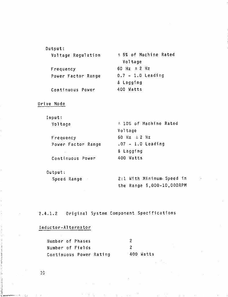
Output: Voltage Regulation
Frequency Power Factor Range
Continuous Power
Dt·; ve Mo de
Input: Voltage
Frequency Power Factor Range
Continuous Power
Output: Speed Range
± 5% of Machine Rated Voltage
60 Hz ± 2 Hz
0.7 - 1.0 Leading & Lagging 400 \{atts
~ 10% of Machine Rated Voltage 60 Hz ± 2 Hz
.07 - 1.0 Leading & Lagging 400 \~ a tt s
2: 1 Wi th Mi n i mum· Speed in the Range 5 f OOO-10,000RPM
2.4.1.2 Original 5ystem Component Specifications
Inductor-Alternator
10
Number of Phases Number of Fields Continuous Power Rating
2
2
400 Watts

Switching Network
Solid State Device Type Thyristor Current Rating
Thyristor Minimum of 125% of Machine Rated CUrr0nt
2.4.2 Modified Syst~ Requirements
Contract modi fi cati on No.1, dated August 1, 1979, repl aced the ori gi nal system performance and component specifications with the following:
2.4.2.1 Modified System Performance Specifications
Generator Mode
Input: Speed Range
Output: DC Voltage Regulation
Continuous Power
Drive Mode
Input: DC Vol tage
Continuous Power
2:1 With Minimum Speed in the Range 5,000-10,000 RPM
+ 5% of Machine Rated Voltage 400 \~atts
t 10% of Machine Rated Voltage 400 \~atts
11

Output~
Speed Range 2:1 With Minimum Speed in the Range 5,000-10,000 RPM
2.4.2.2 Modified System Component Specifications
Inductor-Alternator
12
Number of Phases Number of Fields Continuous Power Rating
2
2
400 Hatts
ORIGINAL PAGE IS OF POOR QUALITY
3. INDUCTOR ALTERNATOR DESCRIPTION
3.1 VARIABLE RELUCTANCE
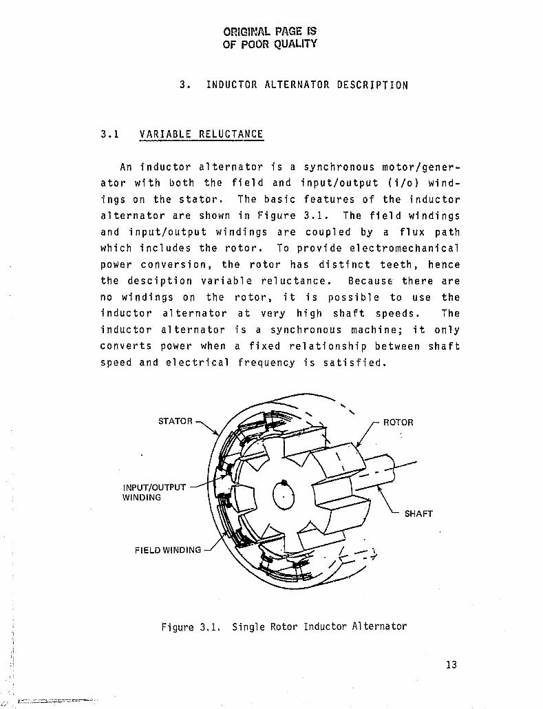
An inductor alternator is a synchronous motor/genera tor wi th both the fi el d and input/output (i /0) wi ndings on the stator. The basic features of the inductor alternator are shown in Figure 3.1. The field windings and input/output windings are coupled by a flux path which includes the rotor. To provide electromechanical power conversion, the rotor has distinct teeth, hence the desciption variable reluctance. Because there are no windings on the rotor, it is possible to use the inductor alternator at very high shaft speeds. The inductor alternator is a synchronous machine; it only converts power when a fixed relationship between shaft speed and electrical frequency is satisfied.
INPUT/OUTPUT WINDING
FIELD WINDING
"
Figure 3.1. Single Rotor Inductor Alternator

When operating as a generator, a time varying mag
netic flux 'is generated. As the rotor turns, the flux generated by the field windings is swept through dif
ferent input/output coils producing a time varying flux
in the input/output coils. A voltage, given by Faraday's Law, is induced in the i/o coils by the flux
variation.
v = N del> dt'
where V = induced voltage in the coil ct> = magnetic flux through the coil N = number of winding turns in the coil.
Each i/o coil sees the flux variation as a triangular waveform in time (Figure 3.2(a)). Due to
Faraday' sLaw, the tri angul ar fl ux waveform induces a square voltage waveform in the i/o windings (Figure 3.2(b)). The amplitude and period of the waveform is
determined by rotor and stator dimensions, winding
parameters, field current, and the shaft speed. The number of voltage waveform periods per rotor revolution
is equal to the number of rotor teeth. Therefore, the frequency of the vol tage waveform (i n Hertz) is the s~aft angular velocity (in revolutions per second) multiplied by the number of rotor teeth. Since an induc
tor alternator is a synchronous motor/generator, it only converts average power when this relationship
between shaft angular velocity and generated electrical
frequency is satisfied.
14
~ I

D, FLUX THROUGH I/O WINDING 0 ~-A & -7- I'~V I V I " I I I I : I I :! I I I
I I
b, VOLTAGE INDLICED IN I/O 0 WINDING
TIME
Fi gure 3.2. Fl ux and Voltage 14aveforms
A simple model of the output circuit includes a vol tage source, the system load, dnd the input/output winding inductance. Because the large fluxes necessary for high power density and efficiency require a small air gap, the i/o winding inductance is large. The i/o winding resistance is therefo,"e assumed to be small compared to the impedance of the i/o winding inductance and is neglected in this model.
15
I I
I
A schematic of this single rotor system during generator operation is shown in Figure 3.3. The field
current IFA produces magneti c f1 ux wh; ch is coup1 ed through the rotor to the i/o vJi ndi ngs. I\s the rotor turns, the chang; /1g magnet; c fl ux in the i/o coi 1 s
induces a voltage VA in the i/o coils. VA drives a circuit consisting of the winding (motor) inductance L and the load RL, which is assumed resistive.
When the inductor al ternator is used as a motor (Figure 3.4), an electrical power supply suppl ies a time varyi ng current to the i/o wi ndi n9. The fl ux produced by thi s current combi nes wi th the fl ux produced by the field current; this total time vatying flux is a rotating flux wave in the ail' gap between the rotor and the stator. Since the rotor is made of ferro-magnetic material, the rotor teeth are forced to rotate with the flux wave. This force produces a torque about the motor shaft, turning the flywheel.
3.2 DUAL ROTOR
The unique aspect of the CSDL dual field concept is the use of dual rotors to eliminate the undesirable effect of the i/o winding inductance. This undesirable effect is a voltage component VL, produced by the
current Ii flowing through the i/O winding, which is out-of-phase with the current 11' This reactive component of power wastes machine capacity and complicates the commutation process. Subtracting a vol tage
VB' at the same frequency and phase as VL, from
16

I I
L_--Jj[
~FLVWHEEL
Figure 3.3. Generator Operation
MACHINE MODEL
fPO WINDING I ______ 1
~ FLVWHEEL
Figure 3.4. Motor Operation
+
+ LOAD RL
POWER SUPPLY
17

the output voltage will Gancel VL, eliminating the reacti ve component of power. The output vol tage and current will then be in phase, simplifying commutation.
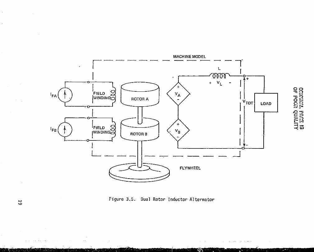
The CSDL concept uses a second rotor and stator (Rotor-B), as indicated in Figure 3.5, to generate the
voltage VO' If the second rotor is on the same shaft as the first, but the stator windings are angularly displaced so that VB leads VA by 90°, the generated voltage VB will always have the proper phase relationship to cancel VL• The proper amplitude for V B can be obtn i ned by adj usti ng the fi el d
current IFB in the second stator. When IFA and I F13 are adjusted correctly, the \'/aveforms shown in
Figure 3.6(a-f) are generated.
The contribution to the output current of one phase (11) of the inductor alternator can now be calcu-1 ated. There are two impedances in the model, (0 L of the motor- inductance and IL of the load. The fundamental frequency (iJ.\) of V A + VB ; s equal to the shaft speed multiplied by the number of rotor
teeth. Because the sha ft speed ; s hi gh, wL » ZL' Neglecting ZL compared to L gives the current as:
where VL Ho\,/ever,
18
1 r Il(t) = -}VL(r)dr,
L
is since
voltage is set
across the inductor.
so that VB =
I:
J->
\0
'FA
'FB
i-I
v---o-----.
I FIELD ~VINDING
IFIELD IWINDING I
~ 0 ----:
I
ROTOR A
L ____ _
~u~ ~~
MACHINE MODEL
L
+ VL
-r I
'r : VTOTf LOAD
I 1-..-1 --,
I I _
'U L--__ ---:-
_--l
FLYWHEEL
Figure 3.5. Dual Rotor Inductor Alternator
00 "TI :.7 -0(:) 0 "" ;'!. a ~; ~ i-.o~ e;: ::t >!."} I~ r,t =i-<(I)

a. VA iNDUCED VOLTAGE IN 1/0 WINDING
(A STATOR, ONE PHASE)
b. VI. VOLTAGE ACROSS 110 WINDING
INDUCTANCE (ONE PHASE)
0
I I I '
oR. : I I: I I Ft I I
I I I I
c. VB INDUCED VOLTAGE IN 1/0 WINDING -=----l----J..----:..-I----!--I-----:..-I---I---°IIR ' I " I I I I ,I [+1' (6 STATOR, ONE PHASE)
I I I I
+=~I ~1 I ~I r' d. VA + VB OPEN CI RCUIT OUTPUT VOLT - 0
AGE WITH B FIELD ADJUSTED FOH RESIS- .•• TIVE LOAD (ONE PHASE)
e. VTOT eVA + VB ~ V L (OUTPUT TER-
MINAL VOLTAGE, ONEriHASE)
f. I, PHASE' OUTPUT CURRENT
(UNRECTIFIED, ONE PHASE)
g. 11 PHASE 1 OUTPUT CURRENT
(RECTIFIED, ONE PHASE)
h. 12 PHASE 2 OUTPUT CURRENT
(RECTIFIED, ONE PHASE)
i. ITOT Q 11 + 12 TOTAL OUTPUT
CURRENT (BOTH PHASES)
Ll U-' U I
I
0 I
I I ., i , : I I
I ,
O~I V\! ~ , I IV'I~V"I I I 1 I I I I
O~~ I I I I ' I I I I I I I
ol~AA.6 I I I I I
0 1 I I I
TIME ~
Figure 3.6. Inductor Alternator Waveforms
20
th~ current is equivalently given by:
For the square wave VB' wave 11 as shown in Figure bution of one phase to the
3.3 DUAL PHASE
this gives the triangular 3.6(f), which is the contritotal output current.
Two output phases are uJed to produce DC output. The output current from the single phase inductor alternator has the form shown in Figure 3.6(f). With rectification this becomes the waveform shown in Figure 3.6(g). Since DC output is desired, a similar current waveform shifted by 90° is needed. This can be generated by a second set of i/o windings on each stator. The second set is wound so that the outputs of the two sets are i denti cal but out of phase wi th each other by 90°. The current from both phases, when added together, is then DC. These waveforms are shown in rig u r e 3. 6 { 9 - i ) • A s c hem at i c 0 f the d u a 1 ph a s e, d u a 1 rotor inductor alternator is shown in Figure 3.7.
3.4 FIELD MODULATION
The inductor alternator can convert variable speed mechanical energy to and from variable frequency electrical energy by the lise of field modulation. Field modulation is obtained by driving the field windings with alternating current at the desired modulation frequency. The generated voltage waveform produced without modulation acts as a carrier for the modulated waveform.

'FB
r---
I I
I
MACHINE MODEL -- - --- -.--
~_R:TOR~ -1-_~ _J: ~d MACHINE
TERMINALS
FLYWHEEL
Figure 3.7. Dual Phase, Dual Rotor Inductor Alternator
BRIDGE RECTIFIER
LOAD
00 "'Zil ,,'~ " .. ~f~ O~ o ~,'
::3 r~
D"" C! ::;:. ~. r- r·; -. --a • .:. -< crJ

There are now two frequenci es of interest in the system. The first is the modulation frequency wm, the frequency at whi ch the converter wi 11 interface wi th the electrical grid. The second is the alternator fre~uency W a. As noted before, thi s frequency is determined by the shaft speed and number of rotor
teeth.
The system is designed with u1a »wm' The alter-nator frequency Wa then acts as a hi gh frequency carrier for the modulation frequency wm. The larger the ratio of u.la to Wm, the better the demodulated output current and voltage waveforms will have the frequency content (energy spectral density) of the modul ati ng waveform. Fie' d modul ated waveforms fOr generator operation are shown in Figure 3.8. A more extensive discussion of field modulation and inductor
alternators is contained in Reference 2.
3.5 CONTROLLER
The controller has three f",ctions. First, it must protect the inductor alternator from excessively high voltages or currents (over-voltage and over-current protection). Second, in applications where the inductor alternator is coupled to a utility line, the controller must synchronize the inductor alternator with the line and control the ampl i tude and phase of the load current. Third, to achieve maximun efficiency and minimum electromagnetic interference (EMI) generation, the controll er must keep the generated vol tage in phase
with the current.
23

a. IFA A-FIELD CURRENT
b. 'FB B-FIELD CURRENT
ORIGiNAL PAGE IS OF POOR QUALiTY
c. V1A VOLTAGE OUTPUT IN PHASE 1 STATOR A "I"-i-+-+-+-+~+-+~r-r-!....--
24
VOl.TAGE OUTPUT 11\1 PHASE 1 STATOR B
f. V 9 TERMINAL VOLTAGE PHASE 1
g. Ig TEliMINAL CURRENT PHASE 1
1":<1 0 D .-'1 n r: ~ r,_ L-.J L.J - - L.J L.J
I I I
A
W-Figure 3.8. Field Modulated Waveforms
(Single Phase)

A block diagram of the controller is shown in Figure 3.9. The controller monitors 1) the line voltage Vo end current 10 , 2) the generated current Ig of each phase of the inductor alternator, 3) the inductor alternator stator position, and 4) a signal indicating desired line current IR or voltage VR• The controller uses this information to 1) set the two field currents IFA and IFB , 2) demodulate the inductor alternator output if necessary, and 3) rectify the inductor alternator generated current.
The block diagram shows the three main 3ubsystems of the controller, 1) the switching and firing circuits, 2) the A-field feedback control, and 3) the B-field feedback control. Vg and Ig are inputs from thp inductor alternator to the switching circuit (demodulator) whose out.put is a lower frequency or DC vol tage and current (V o ' 10 ). The switching circuit is switched by a firing circuit which has as inputs the line cur'rent 10 and voltage Vo ' and the rotor position.
The B-field feedback control circuit uses an encoder which measures the relative positions of the rotor and stator to determine the zero-crossings of the inductor alternator generated voltage Vg. Output current zerocrossings are determined by a polarity indicator on sensed current. Any phase difference between the current and voltage produces an error signal. This error si gnal is then fed to the B-fi el d, dri vi ng the machi ne
to correct the error.
25

SWITCHING AND FIRING CIRCUIT r - -- --, 101
I FIRING ,/'-----. I CIRCUIT 0 I·
I INDUCTOR V 9,19 I SWITCHING ALTERNATOR I CIRCUIT I
L. _ ::::::= __ -1 r - - - -- - - - -- - - - - - - - I
"
ROTOR/STATOR POLARITY PHASE' , POSITION INDICATOR SENSITIVE
I ENCODER DETECTOR I 1_- ______________ -'
8 - FIELD FEEDBACK
VO,IO
TO LINE OR LOAD
-SENSED - Vo OR id PARAMETER I
I ~-------~COMPARATOR I ,-----.-
A - FIELD FEEDBA.CK -------~
REFERENCE PARAMETER VR OR IR
Figure 3.9. Controller Block Diagram

The A - f i ~ 1 a fee db a c k co n t r 0 1 c i rc u i t mod u 1 ate s the higher-frequency ((o.l a ) generated voltage Vg at the frequency wm of the lower frequency vol tage Vo and controls the amplitude of the generated voltage Vg• The control ci rcui t mea sures the ampl i tude di fference between a reference or desired level (V R or IR) and the sensed line parameter (V o or 10 ), The resulting difference signal drives the A-field to adjust the sensed parameter toward the reference level. If the switching circuit is coupled to a line, 1 i ne current 10 is sensed and compared to a reference level for the current I R. In a stand-alone mode J
voltage Vo would be sensed and compared to a reference voltage VR,
27

4. CSDL INDUCTOR ALTERNATOR DESIGN
4.1 MECHANICAL DESIGN
The mechanical design of the inductor alternator is conventional; it has a horizontal shaft and an open frame (Figure 4.1). Thet'e are t\'/o mechanically identical stators and two identical roto.'s mounted along a common shaft. The stators and rotors are both aligned mechanically (Figure 4.2). The ~haft is supported at both ends by ball bearings mounted in the stator housing.
The stators and rotors are constructed from stamped 0.036 cm. Allegheny-Ludlum laminations that are stacked and bonded together. The stators are stamped with 24 winding slots, are 4.1 cm. thick, have an outside diameter of 20.8 em., and have a 10.12 em. inside dia-meter. Each r0tor has six teeth as shown in Figure 4.2
[2J. The rotors have the same thickness as the stators, 4.1 cm., and have a radius of 9.94 em. The radial air gap is 0.09 cm., equal to the difference between the rotor radius and the stator inside radius.
Allegheny,·Ludlum 475Q high-nickel steel was chosen for the lamination material because of its high strength and high permeability. High strength lamina-tions are necessat'Y due to high rotor speeds. High permeability simplifies the analysis of the magnetic circuit (section 4.3) and increases power density and efficiency.
28

INDUCTOR ALTERNATOR
de MOTORI SHAFT GENERATOR
Figure 4.1. CSDL Inductor Alternator
~"'f __
-COMMON SHAFT
ROTOR B
"" . ''''-.,.
Figure 4.2. Cutaway View of Stator and Rotor Alignment
Th i n 11 n h r qUlr rn n or h r ne s on r p h 0 or
no ; n om1n 1 1 u d 1 n h h 1 s n r h n ur II 1 0
h \ 1110 , 1 1 II ri f 0 n i n i r 9 p n h proou In n i ur n. Th r h r w h 0 • . 0 em . 0 h n min 1'1 •
I n or I' c;i n it 0 . 00 "01 • 1 r -n 01 d ne n 1 rIO d. i n •
I"J or. s h us in ,1 n d 1 i nil n 01 r n 1 1 i r p r ne . rom hi n 1 y s ; th
d ion w III 0 h inlll m ehinin 0 h r u r h (j be n I' '/ ) 1 dn nt1 0 h
Th f 1 n 1'0 r c11 m t r i wi h ; rI LOO 2 ern. n min wi h c ne n i . ; n h sh n
r or 0 . ( 00 m. 0 r dOin (TIR).
A r md i n i h h f In ly w b 1 n d b
.1 Lin d Co . c. p 0 d, Th or i ; n unb 1 -an w m· m (wor ) . Th r s i u 1 un 1 -
ne ic; 1. 1. r m-em (wore; s i ) . whi h i S wi hin U 1 i t Y 91' S 1 i h 0 r P(\ r e r rs or sm 11 rmd ur
RI) h h inSld 1 10 r n h ou di In n 0 h ' s r h II r nc o. no 15 em . Th ; n m t r r ne n . i t h ou di m -
re; wi hi n 0 . 000 em . T 1 R .
Th r hous1" i s P 1 ; ; " ( w s r.. ions 110w fo r ju - t m n o . I' POS 1 tion. How II r ,

this adjustment capability was not used during the actual assembly and test. The housing sections were fabricated separately, then pinned together for the final machining of the inside diameter. The housing inside diameter has a tolerance of ±0.00025 Col., and the nominal diameter is 0.001 Col. greater than the
nominal diameter of the stator.
The housing end plates were also fabricated separately then pinned to their corresponding housi~g sections before final machining of the bearing location hol es. The di ameters of the bear; n9 hol es have a 0.00025 Col. tolerance. The concentricity between the housing inside diameter and the bearing holes is 0.0005 em. TIR. The bearings are standard DFSS-16 bearitlgs
with an eccentricity of 0.0013 Col.
A compl ete set of manufacturi ng draw; ngs has been
provided to NASA/LeRC.
4.2 WINDINGS DESIGN
Each stator carries three sets of windings: field, input/output-1, and input/output-2. The winding pattern is shown in Figure 4.3 for 8 stator teeth. The pattern is repeated for the remaining 16 teeth.
Figure 4.3 indicates the reference direction of current in the windings. The stat~rs are wound so that a positive current flow ;s in the direction shown by the
The windings on stator-B are connected to the arrows. windings on stator-A so that the voltage VB
31

ORI~INAL PAGE IS OF POOR QUALITY
.- :~ ---I ,
STATOR B
I/O 1A WINDING
I/O 2B WINDING
I/O 18 WINDING
Figure 4.3. Winding Pattern

produced from stator-B has the correct phase relationshi p to cancel the vol tage VL from the i/o wi ndi ng inductance (Section 3.2).
All windtng wire is copper magnet wire; the wire gauge and number of turns per coil for the six windings are given in Table 4.1. Note that the input/output winding wire is composed of three individual wires
wound together.
4.3 MAGNETIC DESIGN ""'
The magnetic circuit of the inductor alternator is comprised of the stator, rotor, air gap, and windings. The magnetic .:ircuit can be adequately modeled as a time varying, lumped parameter system.
Table 4.1 Inductor Alternator Winding Data ----------'---~ ...
\4INDING TURNS/CO,u:' AWGI NO. COILS
FIELD-A 200 #22 6
FIELD-B 200 #22 6
INPUT/OUTPUT-1A 25 3x(#23) 6
INPUT/OUTPUT-IB 25 3x(#20) 18
INPUT/OUTPUT-2A 25 3x(#20) 18
INPUT/OUTPUT-2B 25 3x(#~:t) 6
lAmerican Wire Gauge
--~ . .,,-----------'
33

The lumped parameter circuit model for the section of stator-A shown in Figure 4.3 is given in Figure 4.4. There are magnetomotive forces (MMF) due to the field, input/output-i, and input/output-2 windings. The magnetic path consists of the gap reluctances Rg between the rotor and stator and the leakage reluctance R .tt bet wee nth est a tor tee t h • The r e 1 u c tan ceo f the iron portions of the path are neglected.
The leakage reluctance R~ is calculated from an infinite parallel plane approximation. Using this approximation,
where d = gap between stator teeth ~o~ permeability of air A = area of gap between
stator teeth.
The gap reluctance at a stator tooth Rg is a function of the rotor position. The minimum value of Rg is calculated as above and is
Rg = 9 --, ~oA
where 9 = gap distance
A = stator tooth area.
The maximum reluctance is approximately ten times this value. Since one rotor tooth covers two stator teeth, R varies in a trapezoidal manner between the
34

MMFbUETO FIELD WINDING
MMF DUE TO I/O 1A WINDING
MMF DUETO
(NI)FA
(NJ)1/01
I/O 2A WINDING (NI)I/02
_t~ATOR Rx
T-
+
+
GAP ? Rg ? Rg ~ Rg ~ Rg ~ Rg ~ Rg ~ Rg ~ Rg
L __ I __ I_ 1--1--1---'--'-
J __. • • , • ~ • •
t ROTOR
Figure 4.4. Lumped Parameter f11agnetic Circuit
00 ~;o
"'05 02 0l'> :4lr .o"tJ t:j.:a »G) r-F-I =4--<.(1)

maximum and minimum values as the rotor turns. This trapezo; dal waveform for the rel uctance Rg across the gap at a stator tooth is shown in Figure 4.5.
The magnetic circuit can be sOlved for the time varying flux in each path. From the solution for the flux, the output voltage can be calculated and, given the load, the output current can be calculated. The effect of various design parameters (shaft speed, geometry, windings) on system performance (output voltage and current) can also be determined.
One imp 0 I' tan t c h a r act e r i s tic i s the 0 pen c i r cui t !)utput voitanc. Hhen the ouput circuit is opened, no currents flow in the in the i/o windings; the magnetic circuit analysis is simplified. A plot of the predicted output voltage versus field current, neglecting saturation, is shown in Figure 4.6.
Another important characteristic ;s the onset of magnetic saturation in the stator teeth. Saturation in the Allegheny-Ludlum alloy occurs at a magnetic field density of about 1.5 tesla. Field currents of about 1 amp will produce this field density. Hhen the stator teeth become saturated, the reluctance of the teeth is nolo n 9 ern e g 1 i g i b 1 e, i. n val ~ d a tin 9 the mod e 1 • The r e -fore, large deviations between model predictions and experimental resul ts are expected at current level s greater than 1 amp (Section 5.3).
36
, " ,

ORIGtr~Al PA~iZ liS orr PCC~ QUALIlY.
t z UJ
a UJ a: u.. a: 0
~ Z a: UJ I-;..J « II
:l
.-It II l-
QJ e .,... I-III ::s III s-QJ > QJ u ;:: ItS ...., U C ::s r-QJ e:: 0. ItS
(,!)
• LO . q-
QJ S-::s Cl
''''' U.

il:' I
~ e:. w l!)
~ ..J 0 > 1-, ::> a. I-::> 0
38
OHU.1~~~r.~~ PAG~ IS Of' POOR QUALITY
250~--~~--~----~----~----~----~----~
200
150
100 / /
50 .-
o~--~~ __ ~ ____ ~ ____ ~ ____ ~ ____ ~ ____ ~ o 1.0
A-FIELD CURRENT
Figure 4.6. Peak-to-Peak Open Circuit Voltage versus IFA (A-Field Current)
1:

4.4 CONTROLLER DESIGN --.;...~~---- ---
Although the design and implementation of the controller is not included in the NASA/LeRC contract, a description ot its partial implementation is included here. The controller can be divided into three subsystems: 1) the firing and switching circuits, 2) the A-fie1d feedback control, and 3) the B-field feedback control.
The feedback control loops for the A and B-fi el ds were not closed electronically as indicated in Figure 3.9. The field currents were controlled manually during the test. The A-fieid current IFA was set to produce the desired voltage output and the B-field was adjusted to minimize the true rms ripple. This corre
sponds to setting VB equal to VL as discussed in Section 3.2. This process is described in the discussion of the test procedures (Section 5.1)
The switching and firing circuits of Figure 3.9 were built. A schematic, showing the important features of the circuits, is contained in Figure 4.7.
The switching circuit is controlled by the firing circuit. The switching sequence depends on the mode of operation of the inductor alternator, motor or genet'ator; the zer'o-crossings of the output voltage Vo; and the zero-crossings of the generated voltage Vg • The firing circuit uses a one-of-eight decoder to process the input information and drive the switching circuit. The decoder has three inputs: one from an exclusive OR
39

,----, I + I I L I I I I I Vg I I I I I I I I I L __ .J IDEALIZED MACHINE PHASE MODEL
Vo _I POLARITY SENSOR
I r1~ 0
POLARITY I ,
I I~
SENSOR
r RoroRmA;)~-' ROTOR I POSITION I ' L~E.:..R __ .J
-18 I L _ --1 DECODER TRtn:H TABLE
I I I I I SCR t INPUTS OUTPUTS
MIG +V 0 ROT 0 1 2 3 4 5 6 7, I SWITCH~G I W:~lWORK I (ONE PHASE)I 1 -, 1 10000000 I
I I
1-11 1001000000 I ~ 1 01 00100000 I
1 0000010000 o 11 00001000 I
I 20 1000000100 I I I~ 0 0 1 0 0 0 0 0 0 1 0 L __ 0 0 0 000 0 000 1 ________________ --1
Note: SCR Switching is Duplicated for Second Machine Phase
Figure 4.7. Switching and Firing Control Circuits with Decoder Truth Table
00 "'" ,0 "tJ£5 ,., ~~" '--' ;~~ 0';;;;, "7'tI ,e _\i.e:!
cO~ C:,; ~tl) I"'" lj,,""i
~c:;

gate that indicates motor or generator operation, one from a pol11rity sensor that indic.ates the polarity of the output vol tage Vo , and one from the rotor posi ti on sen so r t hat i n d i cat est h e pol a r i ty 0 f the i n d u c tor alternator generated voltage Vg • The eight outputs of the decoder, labelled 0-7, are inputs to four OR gates which operate the silicon controlled rectifier (SCR) §witches of the switching circuit.
The truth tabl e for the decoder is shown at the bottom of Figure 4.7. A "1" in the motor/generator column (marked MIG) denotes motor operation; a "0" denotes generator operation. In the output voltage column (marked +V c ), "1" denotes positive output voltage and "0" negative output voltage. In the rotor column (marked ROT), "1" denotes that the rotor
position indicates positive generated voltage Vg , and a "0" indicates negative generated voltage.
The decoder is impl emented by a group of AND gates and inverters as shown in Figul~e 4.7. The output of the decoder is shown driving SCR switches, since the high-power applications expected require them. Transistor switches may be substituted in lower power
applications.
,
41

5. CSDL INDUCTOR ALTERNATOR PERFORMANCE
5.1 TEST SET-UP -~--~
The inductor alternator was tested both as a motor and as a generator, usi n9 a DC motor to turn the ; nductor alternator in the generator test, and as a load in the motor test. As a generator, efficie.ncy and output ripple were measured; as a motor, efficiency was determined. The original concept also ,nvisioned the inductor alternator operating into a fixed frequency AC line (Section 2.2). Although the final design was not optimized for this use; during the test AC operation was demonstrated, and waveforms recorded.
For test purposes, the inductor a1terntor is mounted on a common baseplate with a conventional DC motor, and coupled by a. 5;3 speed increaser, using a belt drive (Figure 5.1). The DC motor is a 27-volt, 30-ampere, 7000 RPM aircraft motor manufactured by ESMCO.
5.2 GENERATOR PERFORMANCE
The measurement procedure for the generator test (see Figure 3.7) was conducted as follows: ,
1. The statftona,"y resistance of the DC drive motor was measured across the motor terminals. The measured value was 0.196 ohms.
42

BELT DRIVE
OF-~--~--------~--~
o '"
INDUCTOR ALTERNATOR
.,
I"'"
Figure 5.1. Inductor Alternator Test Bed

2. The inductor alternator was run with field excitation varied between 0 and 2.5 amps (fields connected in series), over the prescribed 5000-
10000 RPM speed range. The input voltage and current of the DC motor were measured at 500 RPM intervals in this range.
3. Mechanical power, Pm(w) is defined as the difference between input power (Vin'Iin) as measured in (2) and the r2R losses in the DC motor as determined by the current measured in (2) and the resistance measured in (1).
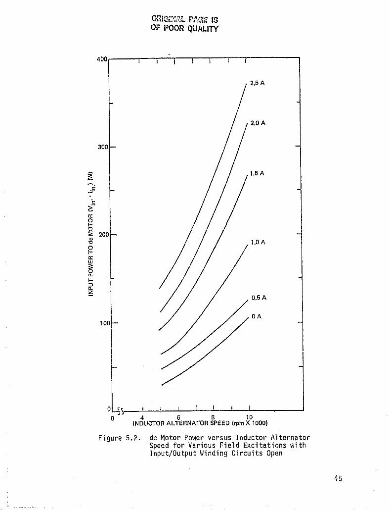
4. Input power as defined above was determined and plotted for various current levels in the field windings. Figure 5.2 indicates the result \'1ith both output winding circuits opened.
5. Tests under load were then performed into 12.5, 25,30, and 100 ohm loads. Measurements \..,ere made with the A-field current set at 50, 100,
150, and 200% of the current 1 evel requi red for the onset of magnetic saturation in the stator (100% = 1.0 amp.). Measurements were made at 1000 RPM intervals between 5000 and 10000 RPM.
6. For each measurement, the B-field current was adjusted to minimize output ripple current as measured by a true rms digital multimeter (DMM). The output windings were connected in parallel as in Figure 3-7.
44
:[ tt
~ --~5
i:: i:.-0: 0 b :a u
"C
0 I-0: W ;: 0 0..
l-;:) 0.. z
O~fG~~{t1t Pt1Q~ IS OF POO~~ QUALITY
400~----~--~--~~--~--~---r'----------'
2.5A
2.0A
300
1.5 A
l I
200 1.0 A
I
101 0.5A
OA
,
I I
I I
o ~~ __ ~~-J __ ~ __ ~ __ ~I~-J __ ~ ____ ~ ____ ~
o 4 6 8 10 INDUCTOR ALTERNATOR SPEED (rpm X 1000)
Figure 5.2. dc Motor Power versus Inductor Alternator Speed for Various Field Excitations with Input/Output Winding Circuits Open

7. In summary, the measurements made at each Of the 1000 RPM intervals specified above were: a) Input voltage to the DC motor
b) Input current to the DC motor c) Current in the A-field d) Current in the B-field e) Output (load) current f) Output (load} current ripp1e
In order to calculate net input power (Pnet(w)), I2R losses in the DC motor and mochani cal losses measured in (3) were subtracted from the total ; nput power to
the DC motor (Vin'Iin)' The formula is thus Pnet(ul))
;; Vin'!in - 12;n R - Pm(Ul).
The output current waveform is shown in Figure 5~3
(a). The generated voltage has waveforms as in Figure 5.3 (b) [2J. These waveforms are closely comparable to
the idealized design waveforms Figure 3.6.
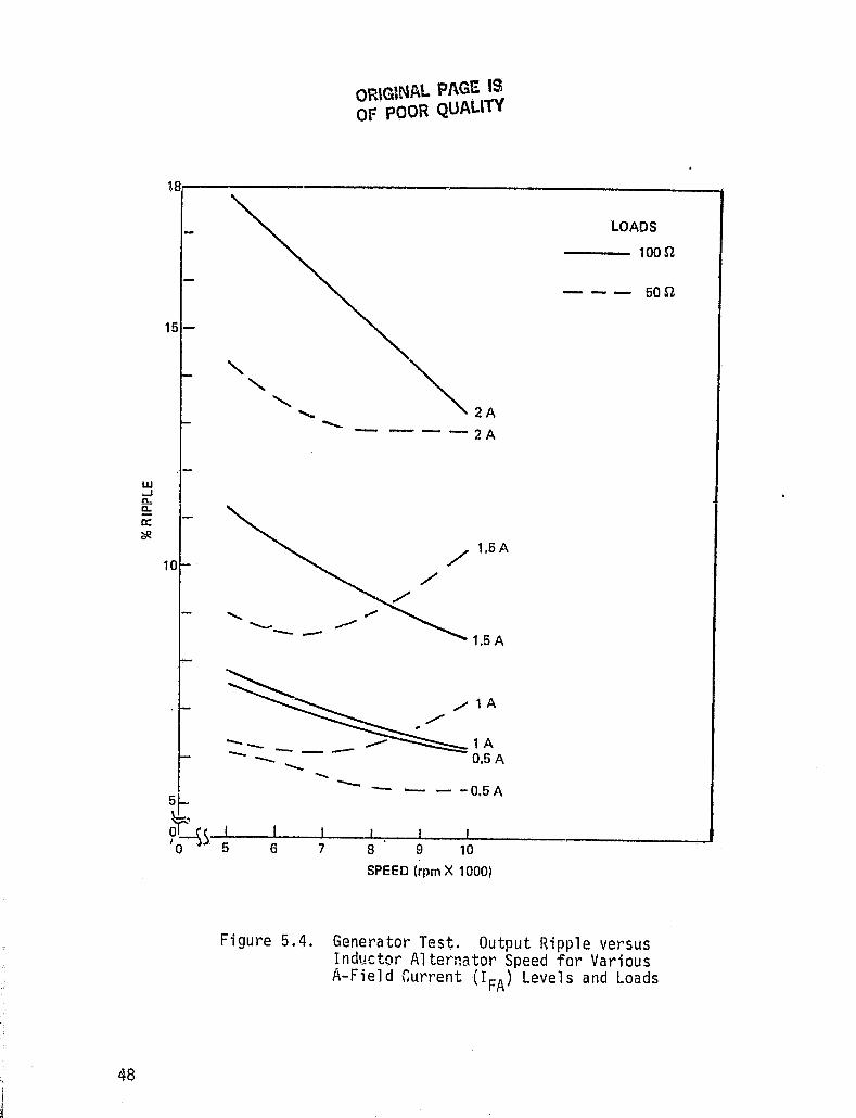
The results were evaluated on the basis of three criteria: ripple, efficiency and power output. Figure 5.4 illustrates the ripple performance of the inductor alternator for tV/O different loads and several levels
of field excitation.
The important aspects of this graph are all explainable in terms of flux saturation ~n tne inductor alternator iron. The overall upward trend in ri ppl e as a function of increasing A-field excitation is directly attri butabl e to saturati on. It shoul d be noted, for instance, that the curves for the 100 ohm load at 0.5
46

B CK A
• • " OUTPUT CURR
VTOT OUTPUT VOLT G ROM ON PHAS (BOTTOM).
COMPAR WITH 3 (1), I )
b. PHASE 1 V A VB (TOP)
PHASE 2 V A V B (BOTTO
Figure 5.3. Generator Test. Inductor Alternator ave orms
ORiGINAL PAGE IS OF POOR QUALITY
181~--------------------------------------__________ ~
15 -
10 .
51-?ss
~2A ----2A
........... --
--- --,-- """- ---I I 5 6 7
./
-I
8
/,1.5A
,,/
1.5 A
/' 1 A /'
lA 0.5A
- -0.5A
I I 9 10
SPEED (rpm X 1000)
LOADS
---loon
- - - 50n
Figure 5.4. Generator Test. Output Ripple versus Inductor Alternator Speed for Various A-Field Current (I FA ) Levels and Loads

and 1.0 amp. excitation are virtually identical. As the excitation is increased above the level of saturation (1.0 amp.), ripple increases rapidly, as shown by the curves for 1.5 and 2.0 amps. At a given current level, the 100 ohm-load curves all trend downward as inductor alternator speed increases. This effect is caused by the output winding inductive reactance, which increases with generated frequency.
The curves for the 50-ohm load exhibit an additional phenomenon. The curve for nominal (1.0 amp.) excitation has a local minimum. The upward trend is due to saturation of the B-field stator. This effect is readily eXplained by the characteristics of the inductor aiternator. Output voltage is proportional to rotor frequency, while output current is constant. Thus as speed increases, B-field field excitation must increase in order to maintain minimum ripple across the fixed load. The 50 ohm load requires twice as much current to maintain a given voltage, and as speed increases, the B-field stator begins to flux-saturate, increasing ripple.
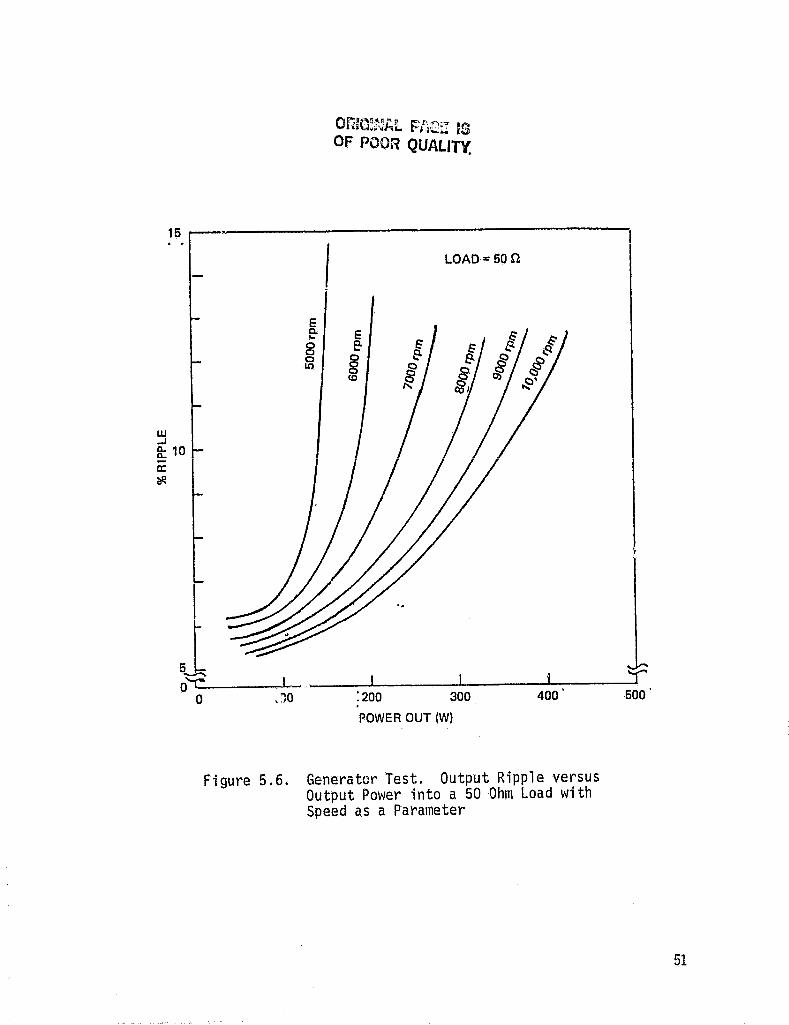
The relation between ripple and output power is shown in Figures 5.5 and 5.6. As can be seen in Figure 5.5, ripple is relatively independent of power output up to the point at which saturation occurs, after which ripple increases dramatically. Notice that higher speeds produce lower ripple. For the 50 ohm load, saturation is reached more rapidly, and the ripple rises steeply.
49

18,------------------------------------------~ LOAD .. loon
16 -
14
~ 12 0-D-
o: ~
10 -
B
. ~ __ ..L-___ _I... ___ .....J.. ____ L_ __ I __ ,_L ___ T
100 201) 300
POWER OUTPUT (W)
Figure 5.5. Generator Test. Output Ripple versus Output Power into a 100 Ohm Load with Speed as a Parameter
W ..I
E e-8 o III
I E e-g (,0
LOAD- 60n
~ 10 0: ~
'.
51 o~~------.~I~,------~I--------~------~~------~~ o .)0 :200 300 400 500'
POWER OUT (W)
Figure 5.6. Generator Test. Output Ripple versus Output Power into a 50 Ohm Load with Speed as a Parameter

The losses are segregated into three components: mechanical, magnetic and electrical. Mechanical losses \vere shown in Figure 5.2. Electrical losses may be reduced by i ncreasi r.g \or ~ copper vol ume of the fi el d windings as shown in Figure 5.7. As can be seen, the efficiency nears its asymptotic value when the winding volume is increa~\ed to 5 times the present volume •.
Output winding losses may be reduced in ('1 'similar manner. For the particular motor design used, however, the output winding resistance was less than 2 ohms, and thus did not produce significant losses over the load range where significant power is produced.
The magnetic losses are intrinsic to the design, and represented by the asymptotic values of the curves in
Figure 5.7. For example, at 10,000 rpm the asymptotic value is about 70%, giving intrinsic magnetic losses of about 30%.
5.3 MOTOR PERFORMANCE
Tests of motor perforE: ...... 'ce (see Figure 5.8) were conducted as follows:
52
1. The inductor alt~rnator rotor was brought to the desired speed by the DC motor.
2 • A dual-phase function generator square waves, 90 0 out of phase and priate frequency, driving the windings.
supplied two at the appro
input/output

70r------r------r------r--'--==~----~----~
60
50
~40 G z w .u
100 n LOAD 1.0 A EXCITATION
CD 10,000 rpm
@ 7000 rpm
® 5000rpm
I~ PRESENT MACHINE
,2 3
NORMALIZED FIELD WINDING VOLUME TIME ACTUAL
5
Figure 5.7. Efficiency (%) versus Normalized Field Winding Volume with Speed as a Parameter. Load = 100 Ohms, Excitation = 1.0 Ampere
53

c.n .po
de POWER SUPPLY
de POWER SUPPLY
FIELD WINDINGS
STATOR A
1----0,;;.." ------.
"STATOR B
INPUT/OUTPUT WINDINGS
1/01 0 7/
~r {a} o-'---r
J ROTOR A I
• ROTOR B
'I {a}
'" 1/02
Figure 5.8. Motor Test Setup
P~':R
AMP
0°
FUNCTION GENERATOR HP-203A
90°
00 "I1:u "'td5 0-0 2 ::o~ 1O'lJ C)::a l>ti) 1m =i_ -<en

3. The outputs of the amplified and applied input/output windings
function generator were to the inductor alternator (Figure 5.9).
4. Hher. field excitation was applied, the motor would tend toward the stable equilibrium point where mechanical and electrical frequencies were equal. In par'ticular, once the two frequencies had been matched within approximately 5 Hz the l~otor would "lock in" and oscillate about the equilibrium point~ with typical settling time of 10 seconds.
5. The stable synchronous frequency described above is the frequency where no net electrical power flows into the inductor alternator. Net power flow was achieved by decreasing power into the DC motor while simultaneously tuning the B-field excitation.
6. At a given speed, maximum power transfer occurs at unstable equilibrium, since any attempt to draw more power causes the inductor alternator to drop out of synchrunization. Measurements were made as close to this limit as was possible gi ven the open loop control. Fi gures 5.9 (a) and (b) are typical of the waveforms obtained in this manner.
Net mechanical output power \'las found to be highly speed-dependent, as shown in Figure 5.10. At lower speeds, mechanical power output increases with
55
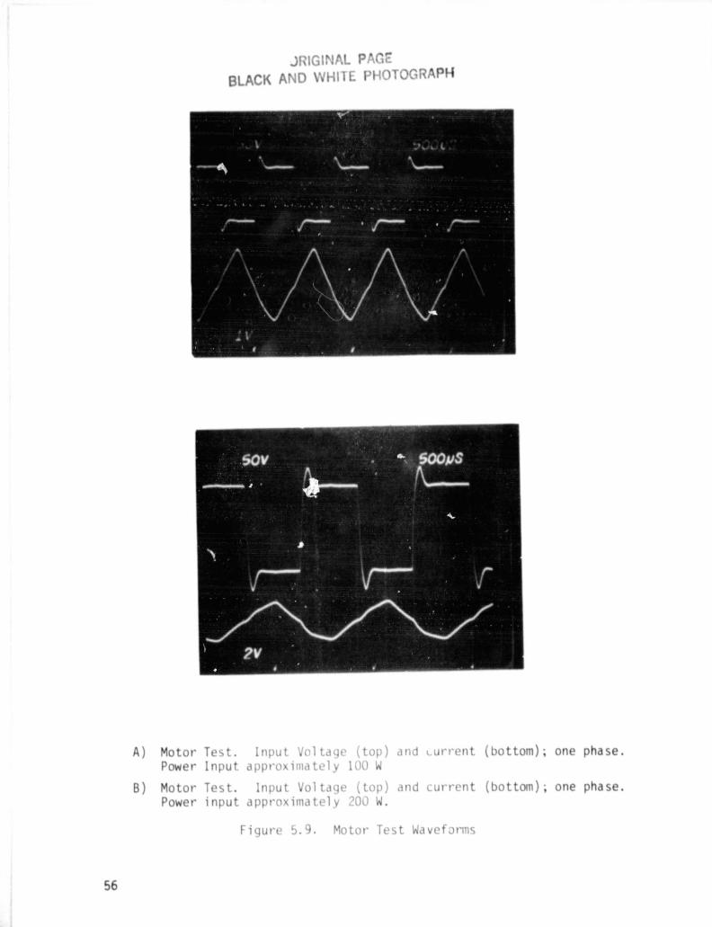
T R P
A) Mo or lnpu ( op) dll n'~n (bo am) . on ph se. Pow r ppro 100
B) nput 01 1 1 (top) dnd CUII' n (bo am) . one pha se. ppro illlll 1 200
Fi ur ~ :.J . otor T> 01'11

~ a: w 3: 0 0-
I-::::l 0-F ::::l 0 ..J <t: t.)
Z <t: J: t.) W ~
180.------------------------------------------------------------·
160
140 -
120 -
10~~ '--
60 -
40- 200 v PIP
100 V PIP 20-
~ S·_-'--__ ...I------IL....---1---..1..-----1-----.l
10 5 6 7 8 9 10
rpm X1000
Figure 5.10. Motor Test. Net Mechanical Output Power versus Speed with ac Drive Voltages of 100 and 200 Volts Peak to Peak
57

increasing speed, as expected, but the magnetic losses shown in Figure 5.2 dominate at the higher speeds. This effect is also visible in the efficiencies plotted in Figure 5.11. Also not,e that while the higher 200V
excitation produces more output power, it is at the cost of significantly greater magnetic losses, which
manifest themselves as lower efficiencies.
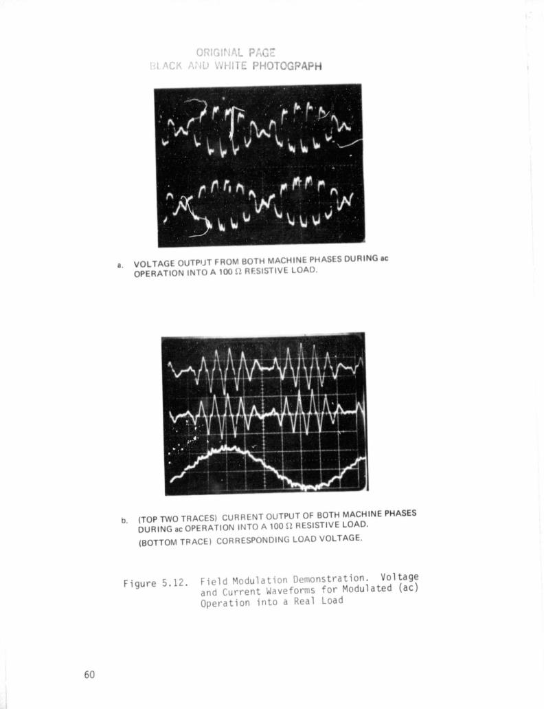
5.4 DEMONSTRATION OF FREQUENCY CONVERSION
The inductor alternator was operated briefly as a frequency converter, wi th the A and B fi el ds exci ted from a 60-Hz line. The inductor alternator was originally designed for this use (see Section 2.2). The test consisted of waveform measurements at various field excitations. Typical results are shown in Figures 5.12
(a) and (b) t2].
58

~ >-u z w U I.L I.L W
60~----~-----~----~-----~------'~------r----~-----~
40 -
20
~100VP/P 200 v PIP
o ))---~I------I~----~I----~I-----~I-----~I------I 5 6 7 8 9 10
rpm X 1000
Figure 5.11. Motor Test. Efficiency versus Speed. ac Drive Voltages of 100 anJ 200 Volts Peak to Peak
60
a. VOLTAGE OUTPIJT FROM BOTH MACHIN PHAS S DURING ae OPERATION INTO A 100 52 R SISTIVE LOAD.
b. (TOP TWO TRACES) CURR NT OUTPUT OF BOTH MACHINE PHASES DURING ae OPERATION INTO A 100 n RESISTIVE LOAD.
(BOTTOM T~ACE) CORRESPONDING LOAD VOLTAGE.
Figure 5.12 . Field odulation Demonstration. Voltage and Current ave orms for Modulated (ac) Operation into a Real Load
6. CONCLUSIONS AND RECOMMENDATIONS
6.1 CONCLUSIONS
Thi s project had as its goal the development of simple, low cost, and power conversion equipment. There were two principle objectives. The first objective was tb demonstrate the performance of Draper Laboratory I s dual fi el d control concept and i ts poten~
ti,al for s'implifying and reducing the cost of required power electronics in flywheel applications. The second objective was to demonstrate that this concept could be impl emented wi th a spec; ally des; gnad inductor al ter,.., nator. The dual field control concept was successfully implemented with an inductor alternator which was operated bidirectionally, a unique application of this type of machi ne. However, the concept coul d be impl emented with any type of wound field synchronous machine. The inductor alternator appears to a good choice for those flywheel power conditioning applications where power
den s i ty i ~ not c r ; tic a 1 .
The most important aspect of dual field control is that the machine output may be phase shifted through the use of the field control so that current is in phase with terminal voltage and has harmonic content
independent of load. There are
tf.!gesin voltage.
having current in Fi rst, the power stage
two pri nci pl e advanphase with terminal can then be made with
low cost naturally commutated thyristors. Second, low current ripple can be obtained without the use of heavy and expensive external filters. Thus the use of lower
61
,. ~
cost power electronics is possible with dual field control as compared to other power converion techinques such as cycloconverters.
The control circuits were not tested experimentally, but by use of manual field controls it was demonstrated that, as predicted, the terrnina1 voltage and current coul d be kept in phase over all operati og condi tions. Output ripple of approximately 6% can be achieved without filtering. If required, output ripple can be reduced further through input/output and field winding modification. The agreement between predicted wave-f\)rms and those measured in the inductor alternator is quite good. Deviation from predicted waveforms is due to the effects of resistance and saturation.
The specific power in the test machine ;$ approximately 400 Watts per 35 lb.s of material (11.4 W!1b). The test machine was deliberately designed using conservative techniques to facilitate analysis. The specific power could b.e increased by approximately a factor of 30 to approximately 300 W/lb in a high density design.
In the present design, machine losses are dominated by field and magnetic losses with efficiencies running in the 40-60% range. These efficiencies can be extended to 80% using the same stators at higher speeds and with additional input/output copper volum.e. I n a
new design power capabilities and efficiency can be traded against copper and air gap volumes. High
62

efficiency requires a large copper volume and small air gap whereas high specific power density requires large air gap and smaller copper volume.
6.2 RECOMMENDATIONS
The inductor alternator with dual field control has applications in areas where extreme ruggedness is requi red and desi gn emphasi sis not on power densi ty. It also has application in areas where the rotor inertia could be utilized effectively, such as energy storage.
Follow-on work should be aimed at developing a complete dual field control system to demofisti-ate low cos tan d s imp 1 i city. I f' a d u a 1 fi e 1 d mac h i n e i sus e d in an electric vehicle \'/here weight is critical, an improved electromagnetic machine should be used. Development of a complete system including power stage, controls, and power converte.r at the 30 Hp (22 kW) level is recommended.
63

7. REFERENCES
1 Eisenhaure, D., G. Oberbeck, S. O'Dea and W. Stanton. Final Report on Research Toward Improved Flywheel suspension and Energy Conservation Systems. C amb ri dge, MA: C'h a rl e s stark 0 ra per Labo ra tory Repo rt R-ll08, November, 1977
2 Bliamptis, T. "A Field Modulated, Variable-Speed to Constant-Frequency Power Converter", Master's Thesis, Massachusetts Institute of Technology, Cambridge, MA, December 1980, also Charles Stark Draper Laboratnry Report T-730
64

![[MC-CSDL]: Conceptual Schema Definition File FormatMC-CSDL]-140515.… · [MC-CSDL]: Conceptual Schema Definition File Format Intellectual Property Rights Notice for Open Specifications](https://static.fdocuments.us/doc/165x107/5f610a51a891c260525fe103/mc-csdl-conceptual-schema-definition-file-format-mc-csdl-140515-mc-csdl.jpg)