This document downloaded from … · Rick Poeppelman, John Jaeger, Larry Von Thun, and Daniel...
191
This document downloaded from vulcanhammer.net vulcanhammer.info Chet Aero Marine Don’t forget to visit our companion site http://www.vulcanhammer.org Use subject to the terms and conditions of the respective websites.
Transcript of This document downloaded from … · Rick Poeppelman, John Jaeger, Larry Von Thun, and Daniel...

This document downloaded from vulcanhammer.net vulcanhammer.info
Chet Aero Marine
Don’t forget to visit our companion site http://www.vulcanhammer.org
Use subject to the terms and conditions of the respective websites.

US Army Corps of Engineers® Engineer Research and Development Center
Computer-Aided Structural Engineering (CASE) Project
Evaluation and Comparison of Stability Analysis and Uplift Criteria for Concrete Gravity Dams by Three Federal Agencies by Robert M. Ebeling, Larry K. Nuss, Fred T. Tracy,
and Bruce Brand
with contributions by
Terry West, Jerry Foster, H. Wayne Jones, Robert Taylor, John Burnworth, Paul Noyes, Rick Poeppelman, John Jaeger, Larry Von Thun, and Daniel Mahoney
The authors and contributors are members of the CASE Massive Concrete Structures subtask group investigating the calculation of uplift pressures in the stability analysis of concrete gravity dams.
January 2000
20000320 012 Approved for public release; distribution is unlimited.

The contents of this report are not to be used for advertising, publication, or promotional purposes. Citation of trade names does not constitute an official endorsement or approval of the use of such commercial products.
The findings of this report are not to be construed as an official Department of the Army position, unless so desig- nated by other authorized documents.
® PRINTED ON RECYCLED PAPER

Computer-Aided Structural Engineering (CASE) Project
ERDC/ITL TR-00-1 January 2000
Evaluation and Comparison of Stability Analysis and Uplift Criteria for Concrete Gravity Dams by Three Federal Agencies by Robert M. Ebeling
Information Technology Laboratory U.S. Army Engineer Research and Development Center 3909 Halls Ferry Road Vicksburg, MS 39180-6199
Fred T. Tracy
Information Technology Laboratory U.S. Army Engineer Research and Development Center 3909 Halls Ferry Road Vicksburg, MS 39180-6199
with contributions by Terry West, Federal Energy Regulatory Commission Jerry Foster, Headquarters, U.S. Army Corps of Engineers H. Wayne Jones, Engineer Research and Development Center Robert Taylor, Great Lakes and Ohio River Division John Burnworth, Vicksburg District Paul Noyes, Seattle District Rick Poeppelman, Sacramento District John Jaeger, Kansas City District Larry Von Thun, retired from the Bureau of Reclamation Daniel Mahoney, Federal Energy Regulatory Commission
The authors and contributors are members of the CASE Massive Concrete Structures subtask group investigating the calculation of uplift pressures in
the stability analysis of concrete gravity dams.
Final report
Approved for public release; distribution is unlimited
Larry K. Nuss
Bureau of Reclamation P.O. Box 25007, D-8110 Denver, CO 80225
Bruce Brand
Federal Energy Regulatory Commission 888 1st Street, NE Washington, DC 20426
Prepared for U.S. Army Corps of Engineers Washington, DC 20314-1000
Under Work Unit 31589

Army Engineer Research and Development Center Cataloging-in-Publication Data
Evaluation and comparison of stability analysis and uplift criteria for concrete gravity dams by three federal agencies / by Robert M. Ebeling ... [et. al]; prepared for U.S. Army Corps of Engineers.
187 p.: ill. ; 28 cm. — (ERDC/ITL ; TR-00-1) Includes bibliographic references. 1. Gravity dams — Stability. 2. Concrete dams — Stability. 3. Structural stability. I. Ebeling,
Robert M., 1954- II. United States. Army. Corps of Engineers. III. U.S. Army Engineer Research and Development Center. IV. Information Technology Laboratory (U.S.) V. Computer-aided Structural Engineering Project. VI. Series: ERDC/ITL TR ; 00-1. TA7 E8 no.ERDC/ITL TR-00-1
Contents
Preface vu
Chapter 1 Stability Analysis of Concrete Gravity Dams with Uplift Water Pressures by U.S. Army Corps of Engineers, Bureau of Reclamation, and Federal Energy Regulatory Commission Criteria 1
1.0 Introduction 1 1.1 Contents 2
Chapter 2 Stability Criteria for Concrete Gravity Dams 5
2.0 Introduction 5 2.1 Corps Design Guidance and Stability Criteria 5
2.1.1 General requirements 5 2.1.2 Stability criteria 6 2.1.3 Overturning stability and resultant location 7 2.1.4 Resultant location criteria 9 2.1.5 Sliding stability 9 2.1.6 Sliding factor of safety 9
2.2 Reclamation Requirements for Stability 11 2.2.1 Safety factors, basic considerations 11 2.2.2 Safety factor: Compressive stress 12 2.2.3 Safety factor: Tensile stress 12 2.2.4 Safety factor: Sliding stability 13 2.2.5 Stability and stress distribution 14 2.2.6 Internal stresses and stability analysis for
uncracked sections 15 2.2.7 Sliding stability 17
2.3 FERC Stability Requirements 17 2.3.1 General requirements 17 2.3.2 Stability criteria 17 2.3.3 Concrete strength criteria 19 2.3.4 Determination of resultant location 19 2.3.5 Sliding stability 20 2.3.6 Cracked base analysis 21

2.4 Comparative Summary of Corps, Reclamation, and FERC Criteria 21 2.4.1 Similarities 21 2.4.2 Differences between Corps and Reclamation
engineering procedures 22 2.4.3 Differences between Corps and FERC engineering
procedures 24
Chapter 3 Uplift and Cracked Base Criteria for Concrete Gravity Dams 25
3.0 Introduction 25 3.1 Uplift Pressure Criteria 25
3.1.1 Corps guidance on computing uplift pressures along the base 26
3.1.2 Reclamation guidance on computing uplift pressures along the base 29
3.1.3 FERC guidance on computing uplift pressures along the base 33
3.1.4 Uplift criteria for the Corps and Reclamation 38 3.2 Cracked Base Criteria 40
3.2.1 Corps guidance on crack initiation/propagation 40 3.2.2 Reclamation guidance on crack initiation 41 3.2.3 Reclamation guidance on crack propagation 42 3.2.4 FERC guidance on crack initiation
and propagation 46 3.2.5 Crack initiation/propagation for the Corps
and Reclamation 47 3.2.6 Crack initiation/propagation for the Corps
and FERC 48
Chapter 4 Calculation of the Length of Cracking Along the Concrete Gravity Dam-to-Foundation Interface by Conventional Equilibrium Analyses and the Corps Uplift Pressure Distribution 49
4.1 Example Concrete Gravity Dam Problem 49 4.2 Stability Calculations Made Using Corps Criteria 51 4.3 Stability Calculations Made Using Reclamation Criteria ... 54 4.4 Stability Calculations Made Using FERC Criteria 64 4.5 Conclusions 64
Chapter 5 Calculation of the Length of Cracking Along the Concrete Gravity Dam-to-Foundation Interface by Conventional Equilibrium Analyses and Using Uplift Pressure Distributions According to the Guidance Employed by the Corps, Reclamation, and FERC 66
IV

5.1 Example Concrete Gravity Dam Problem 66 5.2 Stability Calculations Made Using the Corps
Engineering Procedure and Uplift Pressure Distributions ... 67 5.3 Stability Calculations Made Using the Reclamation
Engineering Procedure and Uplift Pressure Distributions ... 67 5.4 Stability Calculations Made Using FERC
Engineering Procedure and Uplift Distributions 77 5.5 Conclusions 77
Chapter 6 Summary and Conclusions 80
6.1 Stability Criteria for the Corps and Reclamation 80 6.1.1 Similarities 80 6.1.2 Differences 81 6.1.3 Calculation of the length of cracking along the base
of a 100-ft- (30.5-m-) high gravity dam section using the conventional equilibrium analyses and using the Corps uplift pressure distribution 82
6.2 Uplift Pressure Criteria for the Corps and Reclamation .... 82 6.2.1 Uplift criteria for the Corps and Reclamation 82 6.2.2 Crack initiation/propagation for the Corps and
Reclamation 84 6.2.3 Calculation of the length of cracking along the base
of a 100-ft- (30.5-m-) high gravity dam section using the conventional equilibrium analyses and using uplift pressure distributions according to guidance employed by the Corps and Reclamation .. 86
6.3 Stability Criteria for FERC and the Corps 86 6.4 Uplift Pressure Criteria for FERC and the Corps 86
References 88
Appendix A: Corps Definition of Drain Effectiveness Al
Appendix B: Reclamation Definition of Drain Effectiveness and of Crack Initiation Bl
Appendix C: Stability Calculations Made of a 100-ft- (30.5-m-) High Concrete Gravity Dam Section Using the Corps Engineering Procedure and the Corps Uplift Pressure Distribution Cl
Appendix D: Stability Calculations Made of a 100-ft- (30.5-m-) High Concrete Gravity Dam Section Using the Reclamation Engineering Procedure and the Corps Uplift Pressure Distribution Dl
Appendix E: Stability Calculations Made of a 100-ft- (30.5-m-) High Concrete Gravity Dam Section Using the Reclamation Engineering Procedure and the Reclamation Uplift Pressure
v

Distribution El
Appendix F: Stability Calculations Made Using FERC Criteria Fl
SF298
VI

Preface
The work described herein summarizes the results of an investigation of key aspects of guidance published by the U.S. Army Corps of Engineers, the Bureau of Reclamation, and the Federal Energy Regulatory Commission (FERC) used to calculate the stability of gravity dam sections. Funding for the preparation of this report was provided by the Computer-Aided Structural Engineering Program sponsored by Headquarters, U.S. Army Corps of Engineers (HQUSACE), as part of the Civil Works Research and Development Program on Structural Engineering (CWR&D). The work was performed under Civil Works Work Unit 31589, "Computer-Aided Structural Engineering (CASE)," for which Dr. Robert L. Hall, Structures Laboratory (SL), U.S. Army Engineer Research and Development Center (ERDC), is Problem Area Leader and Mr. H. Wayne Jones, Information Technology Laboratory (ITL), ERDC, is the Principal Investigator. The HQUSACE Technical Monitor is Mr. Jerry Foster, CECW-ED.
The work was performed at ITL by Drs. Robert M. Ebeling and Fred T. Tracy, Computer Aided Engineering Division (CAED), ITL, at Reclamation by Mr. Larry K. Nuss, Structural Analysis Group, and at FERC by Mr. Bruce Brand. Dr. Ebeling was author of the scope of work for this work unit. The report was written and prepared by Dr. Ebeling, Mr. Nuss, Dr. Tracy, and Mr. Brand under the direct supervision of Mr. H. Wayne Jones, Chief, CAED, and Mr. Tim Abies, Acting Director, ITL. Mr. John Hendricks, formerly with ITL, and Ms. Vickie Parrish, ITL, provided invaluable assistance in preparing the figures for the report. Contributions and/or review commentary were provided by Mr. Terry West, Federal Energy Regulatory Commission, Mr. Jerry Foster, HQUSACE, H. Wayne Jones, ERDC, Mr. Robert Taylor, U.S. Army Engineer Division, Great Lakes and Ohio River, Mr. John Burnworth, U.S. Army Engineer District, Vicksburg, Mr. Paul Noyes, U.S. Army Engineer District, Seattle, Mr. Rick Poeppelman, U.S. Army Engineer District, Sacramento, Dr. John Jaeger, U.S. Army Engineer District, Kansas City, Mr. Larry Von Thun, retired from the Bureau of Reclamation, and Mr. Daniel Mahoney, FERC. The authors and contributors are all members of the CASE Massive Concrete Structures subtask group formed to investigate the calculation of uplift pressures in the stability analysis of gravity dams.
VII

At the time of publication of this report, Dr. Lewis E. Link was Acting Director of ERDC, and COL Robin R. Cababa, EN, was Commander.
The contents of this report are not to be used for advertising, publication, or promotional purposes. Citation of trade names does not constitute an official endorsement or approval of the use of such commercial products.
VIII

I
1 Stability Analysis of Concrete Gravity Dams with Uplift Water Pressures by U.S. Army Corps of Engineers, Bureau of Reclamation, and Federal Energy Regulatory Commission Criteria
1.0 Introduction
The U.S. Army Corps of Engineers (Corps), the Bureau of Reclamation (Reclamation), and Federal Regulatory Commission (FERC)1 have developed and maintain guidance used to evaluate the stability of gravity dams. All three Federal agencies have engineering procedures based on the use of the conventional equilibrium analysis of a free body diagram of concrete gravity dam section(s). However, there are differences among the published guidance. A Computer-Aided Structural Engineering (CASE) Massive Concrete Structures subtask group was formed involving engineers from three Federal agencies to investigate aspects of guidance published by the Corps, Reclamation, and FERC used to calculate the stability of a concrete gravity dam. This report summarizes the results of this investigation.
1 Starting in 1997 FERC began to revise their guidance on stability analysis and uplift criteria for concrete gravity dams. The FERC guidance contained in this technical report is based on the 1999 (summer) draft. By the summer of 1999 this FERC draft guidance had undergone peer review by FERC engineers and is currently undergoing peer review by engineers outside FERC.
Chapter 1 Stability Analysis of Concrete Gravity Dams with Uplift Water Pressures

The objective of this report is to identify similarities, as well as differences, in the calculation of uplift as well as crack initiation and crack propagation in the stability of concrete gravity dams as an initial step toward evaluating a need for a unified Federal criteria. An important issue regarding the engineering proce- dures as practiced by both agencies when performing stability calculations is how uplift water pressures are to be computed and applied in the calculations. This study is limited to an imaginary section made through the base of a dam.
Factors affecting the evaluation of dam stability include the following:
a. Drain effectiveness.
b. Method of determining crack length.
c. Assumptions of crack orientation.
d. Position of the dam-to-rock foundation resultant force within the kern versus stress at heel.
e. Shear strength (cohesion, friction angle).
/. Tensile strengths.
g. Unit weight of concrete.
h. External loads (reservoir, tailwater, post-tensioning, overtopping flows).
i. Factors of safety.
Basically the methods used by the three agencies to analyze concrete gravity dams using limit equilibrium methods are very similar. Slightly different methods and analytic procedures are used, but given the same forces, the same results are obtained. The key differences are the nonsite-specific equations used to calculate uplift pressures, the drain effectiveness, and stability criteria for factors of safety, allowable compressive strength, and allowable tensile strength.
1.1 Contents
Chapter 2 summarizes the stability criteria and the engineering procedures used to calculate the stability of concrete gravity dams according to guidance published by the three Federal agencies. Similarities as well as differences in the stability criteria and engineering procedures used by the three agencies are discussed.
Chapter 3 summarizes the uplift and cracked base criteria used to calculate the stability of concrete gravity dams according to guidance published by the
Chapter 1 Stability Analysis of Concrete Gravity Dams with Uplift Water Pressures

three Federal agencies. Similarities as well as differences in the engineering procedures used by the three agencies are discussed.
Chapter 4 summarizes the calculation of the stability of an example gravity dam section using the three engineering procedures described in Chapter 2 but using the Corps uplift pressure distribution. The uplift water pressure distribution applied in the three sets of calculations is stipulated as that developed in accordance with guidance published in Engineer Manual (EM) 1110-2-2200 (Headquarters, U.S. Army Corps of Engineers (HQUSACE) 1995) used to design gravity dams and summarized in section 3.1.1 in Chapter 3 of this report. The objective is to demonstrate that the equations used in the calculations, as described in the guidance publications of the three Federal agencies, reflect the same engineering mechanics for the stability problem. Specifically, the methodologies used by the three agencies to calculate crack potential and crack extent are demonstrated.
Chapter 5 summarizes the calculation of the stability of the example gravity dam section of Chapter 4 using the three engineering procedures described in Chapter 2. The uplift pressure distribution is assigned as stipulated by the guid- ance published by each of the three agencies. The objective is to demonstrate the impact of uplift distributions on the stability calculations, expressed in terms of crack potential or crack extent.
Chapter 6 summarizes the results of this study and the factors affecting the calculation of uplift pressures and dam stability according to guidance published by the Corps, by Reclamation, and by FERC.
Appendix A describes the Corps definition of drain effectiveness for the cases of tailwater below and above the floor of the drainage gallery. The example used is the case of a crack that extends along the base from the upstream face of the dam to a point somewhere before the line of foundation drains.
Appendix B describes the Reclamation definition of drain effectiveness for the cases of tailwater below and above the floor of the drainage gallery without a crack. The scenario with a crack is not applicable because the drain is assumed ineffective once a crack forms.
Appendix C lists the derivation of the base pressure equation (effective stresses) used in the Corps guidance and outlines the calculations made in the stability calculation for the Chapter 4 example dam problem. The Corps' methodology to calculate crack potential and crack extent is demonstrated.
Appendix D lists the base pressure equation (total stresses) used in the Recla- mation guidance and outlines the calculations made in the stability calculation for the Chapter 4 example dam problem. The uplift water pressure distribution applied in this set of calculations is stipulated as that developed in accordance with guidance published by the Corps. Reclamation methodology to calculate crack potential and crack extent is demonstrated.
Chapter 1 Stability Analysis of Concrete Gravity Dams with Uplift Water Pressures

Appendix E outlines the calculations made in the stability calculation for the Chapter 5 example dam problem using the Reclamation guidance and Reclamation uplift pressure distribution. Reclamation criteria for uplift are used to demonstrate the differences in uplift assumptions between the two agencies. The geometry of this example dam is the same as was used in Chapter 4.
Appendix F outlines the calculations made in the stability calculation for the Chapter 5 example dam problem using the FERC guidance and FERC uplift distribution. In this problem the FERC and Corps uplift distributions are the same with the exception that FERC uses a slightly different value for the unit weight of water than is typically assumed by the Corps.
Chapter 1 Stability Analysis of Concrete Gravity Dams with Uplift Water Pressures

2 Stability Criteria for Concrete Gravity Dams
2.0 Introduction
The stability criteria and the engineering procedures used to calculate the sta- bility of concrete gravity dams according to guidance published by the Corps, Reclamation, and FERC are summarized in this chapter. The guidance for the design of gravity dams is given in terms of the conventional equilibrium method of analysis, which is based largely on classical limit equilibrium analysis. Only that portion of guidance relating to an imaginary section made through the base of the dam is described in detail. The similarities as well as differences in the engineering procedures and stability criteria used by the three agencies are also summarized.
2.1 Corps Design Guidance and Stability Criteria
The stability analysis is described in EM 1110-2-2200 (HQUSACE 1995) on concrete gravity dam design, and stability criteria are given in EM 1110-2-2100 on stability analysis of concrete structures (HQUSACE 1999).1 The following subsections summarize the Corps' design guidance contained within EM 1110-2- 2200 and EM 1110-2-2100 and pertaining to stability considerations along an imaginary section made through the base of the dam.
1 Starting in 1997 USACE began to revise and consolidate their guidance on stability criteria for concrete gravity dams and other hydraulic structures. The Corps guidance contained in this technical report is based on the summer 1999 draft of this guidance (Engineer Manual (EM) 1110- 2-2100). By the summer of 1999 this Corps draft guidance had undergone peer review by District engineers as an Engineer Circular, designated as EC 1110-2-291. EM 1110-2-2100 is in the final stages of preparation at the time of publication of this report.
Chapter 2 Stability Criteria for Concrete Gravity Dams

2.1.1 General requirements
The following are basic stability requirements for a concrete gravity dam for all conditions of loading:
a. That it be safe against overturning at any horizontal plane within the structure, at the base, or at a plane below the base.
b. That it be safe against sliding on any horizontal plane within the structure, at the base, or at a plane below the base.
c. That the allowable unit stresses in the concrete or in the foundation material shall not be exceeded.
Characteristic locations within the dam in which a stability criteria check should be considered include planes where there are dam section changes and high con- centrated loads. Large galleries and openings within the structure and upstream and downstream slope transitions are specific areas for consideration.
2.1.2 Stability criteria
The stability criteria for concrete gravity dams for each load condition are listed in Table 1 (EM 1110-2-2100). Seven basic loading conditions generally used in concrete gravity dam designs are discussed in EM 1110-2-2100. Three loading conditions are used to categorize the frequency of occurrence of the seven loading conditions during the design life of the concrete gravity dam (Table 2). The loading condition ranges from the frequent usual loading condition to the less frequent unusual and extreme loading conditions.
Table 1 Stability and Stress Criteria (Table 4-1 in EM 1110-2-2200; Minimum Sliding Factor of Safety Factors taken from Table 3-2 for Critical Structures with Ordinarv Site Information in EM 1110-2-2100)
Load Condition
Resultant Location at Base
Minimum Sliding Factor of Safety
Foundation Bearing Pressure
Concrete Stress
Compressive Tensile
Usual Middle 1/3 2.0 <; allowable 0.3 fc' 0
Unusual Middle 1/2 1.5 < allowable 0.5 fe' 0.6 f™
Extreme Within base 1.1 i 1.33 x allowable 0.9 fc' 1.5 f„'»
Note: fc' is 1 -year unconfined compressive strength of concrete. The sliding factors of safety are based on a comprehensive field investigation and testing program. Concrete allowable stresses are for static loading conditions. Lower minimum values of the sliding factor of safety are stipulated by EM 1110-2-2100 for critical structures with well-defined site information.
Chapter 2 Stability Criteria for Concrete Gravity Dams

Table 2 Corps Loading Conditions (EM 1110-2-2100)
Condition No. Load Condition Description
1 Unusual loading condition Construction
Dam structure complete. No headwater and tailwater.
2 Usual loading condition Normal operating
Headwater at normal pool (worst conditions with 10-year return period).
Minimum tailwater corresponding with this headwater. Uplift. Ice and silt pressure, if applicable.
3 Unusual loading condition Infrequent flood
Pool at an elevation representing a flood event with a 300-year return period.
Minimum corresponding tailwater. Uplift. Ice and silt pressure, if applicable.
4 Extreme loading condition Construction with Operational Basis
Earthquake
Operational Basis Earthquake (OBE). Horizontal acceleration in upstream direction. No headwater or tailwater.
5 Unusual loading condition Coincident pool with Operational Basis
Earthquake
Operational Basis Earthquake (OBE). Horizontal acceleration in downstream direction. Coincident pool condition (pool elevation that is equal or
exceeded 50 percent of the time). Uplift at preearthquake level. Silt pressure, if applicable. No ice pressure.
6 Extreme loading condition Coincident pool with Maximum Design
Earthquake
Maximum Design Earthquake (MDE). Horizontal acceleration in downstream direction. Coincident pool condition (pool elevation that is equal or
exceeded 50 percent of the time). Uplift at preearthquake level. Silt pressure, if applicable. No ice pressure.
7 Usual, unusual, or extreme loading condition Maximum Design Flood
Combination of pool and tailwater that produces the worst structural loading condition, with an unlimited return period (may be any event to the Probable Maximum Flood).
Uplift. Silt pressure, if applicable. No ice pressure.
2.1.3 Overturning stability and resultant location
The overturning stability is calculated by applying all the vertical forces (N) and lateral forces for each loading condition to the Figure 1 dam and then sum- ming moments (EM) caused by the consequent forces about the center line along the base for the two-dimensional dam section being analyzed. The sum of vertical forces includes the resultant force to the uplift pressure distribution along the base. Thus, N, the vertical component of the resultant force R, is the resultant of the effective base pressure distribution. The resultant location is offset from the center line of the dam by a distance e and computed by:
Chapter 2 Stability Criteria for Concrete Gravity Dams

Headwater
V Weight
Drainage Gallery
Tailwater
H
Uplift Pressures
Where:
Weight R N T
Weight of gravity dam Resultant Summation of (effective) vertical forces Summation of horizontal forces
Figure 1. Resultant forces acting on the free body diagram of a gravity dam section according to EM 1110-2-2200
8 Chapter 2 Stability Criteria for Concrete Gravity Dams

£ Moments about center line at base n^. e = (1)
The methods for determining uplift forces will be described in Chapter 3.
2.1.4 Resultant location criteria
When the resultant of all forces acting above any horizontal plane through a dam intersects that plane outside the kern (the middle third for two-dimensional loads), a noncompression zone will result for a linear distribution of base pressure. A linear base pressure is assumed in the conventional equilibrium analysis for the gravity dam section as shown in Figure 2 (Figure 4-2 in EM 1110-2-2200). Three key relationships between the base area in compression and the location of the resultant are shown in Figure 2. The Figure 2 base pressure distributions represent the effective normal stress, P', along the base since uplift pressures have been included in the normal force N and the EM calculations. The effective normal pressure is equal to total normal pressure minus the uplift pressure. For usual loading conditions, it is generally required that the resultant along the plane of study remain within the middle third to maintain compressive stresses in the concrete (Table 1). For unusual loading conditions, the resultant must remain within the middle half of the base. For extreme load conditions, the resultant must remain sufficiently within the base to assure that base pressures are within prescribed limits.
2.1.5 Sliding stability
The sliding stability is based on a factor of safety as a measure of determining the resistance of the structure against sliding. The multiple wedge analysis is used along the base and within the foundation. The equations used in the multi- ple wedge analysis are summarized in Chapter 4 of EM 1110-2-2200.
2.1.6 Sliding factor of safety
The sliding factor of safety (FS) is conceptually related to failure, the ratio of the shear strength (xF), and the applied shear stress (x) along the failure planes of a test specimen according to
FS _ XF _ ( o tan (|) + c ) (2)
where xF = a tan (|> + c, according to the Mohr-Coulomb failure criterion with o being the normal stress. The sliding factor of safety is applied to the material strength parameters in a manner that places the forces acting on the structure and rock wedges in sliding equilibrium.
Chapter 2 Stability Criteria for Concrete Gravity Dams

p'min = -£-(1--^-)
6e Pmax = ^ (1 + ^-)
100% BASE IN COMPRESSION RESULTANT WITHIN CENTRAL
THIRD OF BASE Heel
P min
100% BASE IN COMPRESSION. RESULTANT AT 1/3 POINT (e = {?).
L -
R\JN I A* Toe»
P max
P max
LEGEND
P''= FOUNDATION PRESSURE AT BASE (EFFECTIVE STRESS)
L = BASE WIDTH OF DAM
e = ECCENTRICITY OF RESULTANT
R = RESULTANT AT BASE
N = NORMAL COMPONENT OF R
LESS THAN 100% BASE IN COMPRESSION. RESULTANT OUTSIDE CENTRAL THIRD.
b=3s
P max
Figure 2. Relationship between base area in compression and resultant location (adapted from Figure 4-2 in EM 1110-2-2200)
10 Chapter 2 Stability Criteria for Concrete Gravity Dams

The sliding factor of safety is defined as the ratio of the maximum resisting shear (TF) and the applied shear (7) along the slip plane at service conditions:
FS = — N tea ^ + c L „) T T
where
N = resultant of forces normal to the assumed sliding plane
(|) = angle of internal friction
c = cohesion intercept
L = length of base in compression for a unit strip of dam
The effects of uplift forces are to be included in the sliding analysis when calcu- lating the force N. Section 4-6 in Chapter 4 of EM 1110-2-2200 contains addi- tional details on the basic concepts, assumptions, and simplifications regarding the sliding stability of concrete gravity dams.
2.2 Reclamation Requirements for Stability
The requirements for stability of concrete gravity dams is described in the Bureau of Reclamation's Manual on the Design of Small Dams (1987). The following subsections summarize Reclamation's design guidance pertaining to stability considerations along a representative section through the base of the dam.
2.2.1 Safety factors, basic considerations
All loads used in the design should be chosen to represent, as nearly as can be determined, the actual loads that will occur on the structure during operation. Section 8.15 of Chapter 8 (Reclamation 1987) discusses the loading combinations to be considered in the analyses. These loading combinations are categorized as either usual, unusual, or extreme loading combinations based on the frequency of the loading event (Table 3). Safety factors for gravity dams are based on the use of the gravity method of analysis, and those for foundation sliding stability are based on an assumption of uniform (shear) stress distribution on the plane being analyzed. A concrete gravity dam must be designed to resist, with ample safety factor, internal stresses and sliding failure within the dam and foundation. Subsections 2.2.2 through 2.2.5 discuss recommended allowable stresses and safety factors.
Chapter 2 Stability Criteria for Concrete Gravity Dams 11

Table 3 Reclamation Load Combinations
Condition No. Load Condition Description
1 Usual load combination Normal reservoir elevation. Uplift. Silt. Ice. Tailwater. Minimum usual temperature.
2 Unusual load combination Maximum reservoir elevation. Uplift. Silt. Tailwater. Minimum usual temperature.
3 Extreme load combination Usual loading, plus Maximum Credible Earthquake.
4 Other loads and investigations Usual or unusual load combinations with drains inoperative. Dead loads. Other load combinations at engineer's discretion.
2.2.2 Safety factor: Compressive stress
The maximum allowable compressive stress for concrete in a gravity dam section subjected to any of the usual load combinations should not be greater than the specified compressive strength divided by a factor of safety of 3.0. Under no circumstances should the allowable compressive stress for the usual load combinations exceed 1,500 lb/in2 (10,342.14 kPa).
A safety factor of 2.0 should be used in determining the allowable compressive stress for the unusual load combinations. The maximum allowable compressive stress for the unusual load combinations should never exceed 2,250 lb/in2 (15,513.2 kPa).
The maximum allowable compressive stress for the extreme load combinations should be determined in the same way using a safety factor of 1.0 or greater if specified by the designer.
Safety factors of 4.0, 2.7, and 1.3 should be used in determining allowable compressive stresses in the foundation for usual, unusual, and extreme load com- binations, respectively. (Note: Compressive strength of foundation materials should be based on unconfined compressive strength.)
2.2.3 Safety factor: Tensile stress
The safety factor s on the tensile strength of concrete should be 3.0 for usual, 2.0 for unusual, and 1.0 for extreme load combinations in the computation of the allowable stress at the upstream face in Equation 4. The allowable value for oz„ for usual load combinations should never be less than 0. Cracking should be
12 Chapter 2 Stability Criteria for Concrete Gravity Dams

assumed to occur if the total stress at the upstream face az is less than ozu. Cracking is not allowed for usual and unusual load combinations for new dams; however, cracking is permissible for the extreme load combination if stability is maintained and allowable stresses are not exceeded. In order not to exceed the allowable tensile stress, the minimum allowable compressive stress computed without internal water pressure should be compared with the following expression, which takes into account stress from internal water pressure and the tensile strength of the concrete at the lift surfaces:
= pwh (4)
where
oz„ = minimum allowable compressive stress at the upstream face
p = reduction factor to account for drains
w = unit weight of water
h = depth below water surface (= if j)
/, = tensile strength of concrete at lift surfaces
5 = safety factor
All parameters must be specified using consistent units.
The value of the drain reduction factor/? should be 1 for dams without tail- water and if drains are not present or are inoperable, or if cracking has occurred, or is computed to occur, at the upstream face. The value of p should be 0.4 if drains are present and effective and there is no tailwater. The drains must be located at a distance of 5 percent H1 from the heel and have a drain effectiveness of 66 percent (E = 0.66). Reclamation typically places drains at this location. All other conditions produce different values of p. Additional details regarding the background for the value of p and uplift pressures will be described in Chapter 3.
2.2.4 Safety factor: Sliding stability
The shear-friction safety factor provides a measure of the safety against sliding or shearing of any section. The following expression is the ratio of resisting to driving forces and applies to any section in the structure, in the foundation, or at its contact with the foundation for the computation of the shear- friction safety factor, Q:
Chapter 2 Stability Criteria for Concrete Gravity Dams 13

14
„ _ CA + ( IN + YU ) tan (|) ,- Ö = ^ W
where
C = unit cohesion
A = area of section considered (width x uncracked length)
EiV = summation of normal forces
SZ7 = summation of uplift forces (uplift is negative according to the sign convention)
tan (|) = coefficient of internal friction (incorporating effects of roughness or "apparent cohesion" as appropriate)
HV = summation of shear forces
All parameters must be specified using consistent units.
The minimum shear-friction safety factor within the dam or at the concrete- rock contact should be 3.0 for usual, 2.0 for unusual, and greater than 1.0 for extreme load combinations. The safety factor against sliding or any plane of weakness within the foundation should be at least 4.0 for the usual, 2.7 for unusual, and 1.3 for the extreme load combinations. If the computed safety factor is less than required, foundation treatment can be included to increase the safety factor to the required value. For concrete structures on soil-like foundation materials, it is usually not feasible to obtain safety factors equivalent to those prescribed for structures on competent rock. Therefore, safety factors for concrete dams on nonrock foundations are left to the engineering judgment of an experienced designer. If the amount of intact rock through a foundation plane cannot be reliably determined and continuous joint or shear planes are assumed, then factors of safety of 2.0 for usual, 1.5 for unusual, and 1.0 for extreme loading combinations and a Newmark displacement analysis are applied to determine acceptability of implied displacements under earthquake loadings.
2.2.5 Stability and stress distribution
The stability of the gravity dam section is assessed using the stress distribu- tions along imaginary section(s) made through the dam, through the dam-to- foundation interface, and/or within the foundation. New dams are designed not to crack for all static loading combinations; however, cracking is permissible for earthquake loading if it can be shown that stress, displacement, and stability criteria are satisfied during and after the earthquake event. It is also permitted for analyses to indicate that cracking is likely for existing dams for the condition
Chapter 2 Stability Criteria for Concrete Gravity Dams

of maximum water surface with drains inoperative, as long as it can be shown that stress and stability criteria are satisfied.
2.2.6 Internal stresses and stability analysis for uncracked sections
New dams are designed not to crack for all static load combinations. This subsection summarizes the considerations relating to sliding stability and internal stresses of uncracked sections. Recall that the overturning stability of the gravity dam section is assessed using the stress distributions along representative sec- tion^) through the dam, through the dam-to-foundation interface, and/or within the foundation. All stability analyses of gravity dam section(s) begin with the assumption of uncracked sections.
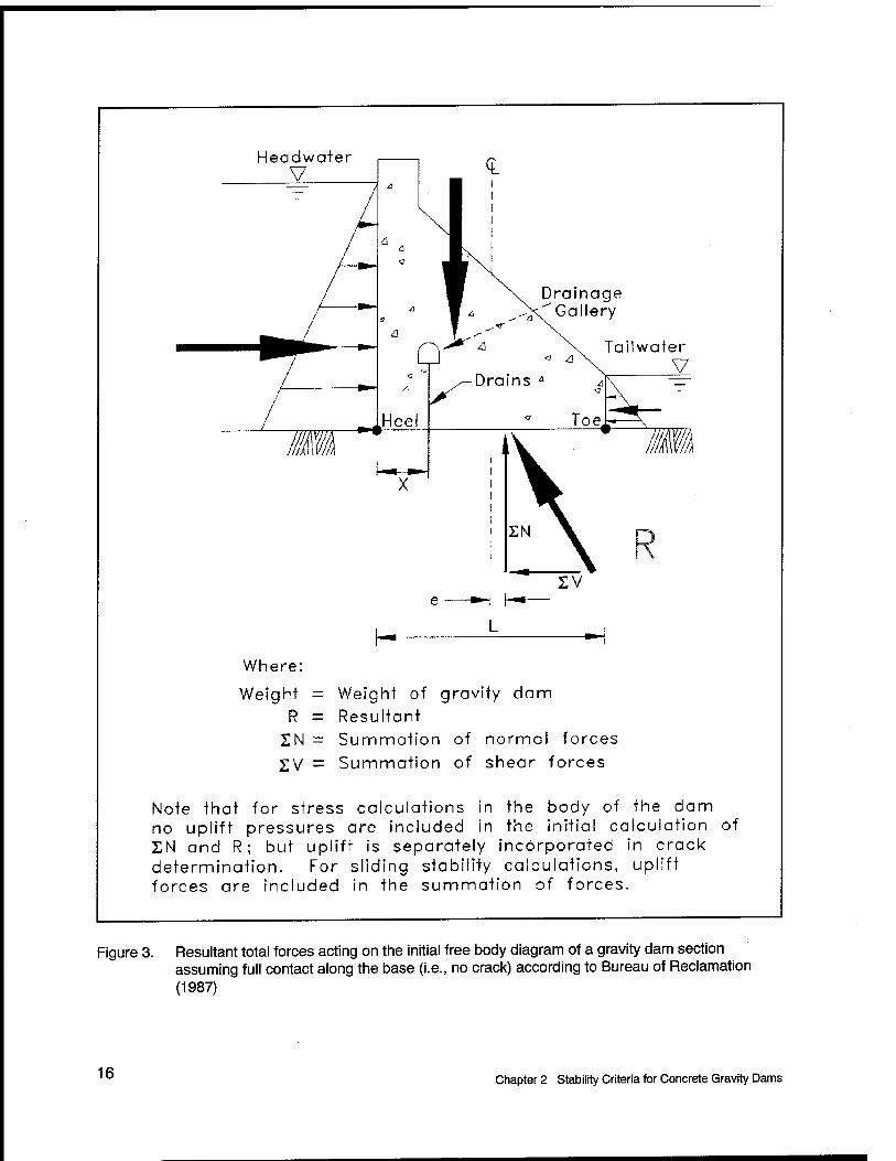
For most concrete gravity dams, internal stresses can be adequately determined for a cross section (Figure 3) using a two-dimensional limit equilibrium method of analysis assuming a linear distribution of stress acting normal to the base of the dam through which the imaginary section is made. It is applicable for the general case of a gravity section with a vertical upstream face and a constant downstream slope and for situations where there is a variable slope on either or both faces. The two-dimensional limit equilibrium method is substantially correct, except for horizontal planes near the base of the dam where the foundation yielding is not reflected in stress calculations. Therefore, where necessary in the judgment of an experienced design engineer, finite element modeling should be used to check stresses near the base of a dam. Other methods of analysis such as the finite element method should also be used to analyze three-dimensional behavior. Grouted or keyed contraction joints and monolithically constructed roller-compacted concrete dams also exhibit three- dimensional behavior, especially along changes in foundation grade or foundation deformation modulus, the effects of which are not revealed in the two-dimensional analysis.
The conventional equilibrium method of analysis uses the engineering mechanics flexure formula to determine the linear stress distribution along a horizontal plane within the dam:
EW ^ TMy ,~
where
a2 = (total) normal stress on a horizontal plane
T,W = resultant vertical force from forces above the horizontal plane
A = area of horizontal plane considered (width x L)
EM = summation of moments about the center of gravity of the horizontal plane
Chapter 2 Stability Criteria for Concrete Gravity Dams 15
Headwater V <L
Drainage Gallery
Tailwater V
Where:
Weight R
IN sv
Weight of gravity dam Resultant Summation of normal forces
Summation of shear forces
Note that for stress calculations in the body of the dam no uplift pressures are included in the initial calculation of £N and R; but uplift is separately incorporated in crack determination. For sliding stability calculations, uplift forces ore included in the summation of forces.
Figure 3. Resultant total forces acting on the initial free body diagram of a gravity dam section assuming full contact along the base (i.e., no crack) according to Bureau of Reclamation (1987)
16 Chapter 2 Stability Criteria for Concrete Gravity Dams

y = distance from the neutral axis of the horizontal plane to where oz is desired
/ = moment of inertia of the horizontal plane about its center of gravity (width x ÜIY1 for a solid, rectangular section)
Equation 6 is used by Reclamation to compute the total vertical (z direction) normal stresses (oz) at the heel and toe of a gravity dam section. The vertical forces 2W and moments SM are calculated about the center of the uncracked base. Similarly, the total vertical stress can be calculated, as shown in Figure 4, by computing the location of the resultant forces above the horizontal plane and using the sum of the vertical forces EiV and the eccentricity e. Forces from uplift pressures below the horizontal plane are not included in the computation of total stress. Reclamation calculates and includes stresses induced from uplift (o2M) separately as described in the tensile criteria discussed in section 2.2.3 and crack initiation discussed in Chapter 3. Typically, the largest compressive stress is at the toe of the dam and a lesser compressive stress or tensile stress is at the heel of the dam.
2.2.7 Sliding stability
The horizontal force, E V on the Figure 3 imaginary section made through the base of the concrete gravity dam, tends to displace the dam in a horizontal direc- tion (downstream). This tendency is resisted by the shear resistance of the con- crete or the foundation. The rigid block method of analysis, which assumes a uniform shear stress distribution on the potential failure plane analyzed, should be sufficient for most cases. However, for cases where the rigid block analysis may not be applicable, such as cases involving a variable foundation deformation modulus or special cases involving foundation treatment, finite element modeling may be warranted to more accurately predict stress levels and distributions. The shear-friction safety factor is computed using Equation 5 for each imaginary section being investigated and the results compared against the design criteria given in section 2.2.4.
2.3 FERC Stability Requirements
2.3.1 General requirements
FERC general requirements for gravity dam stability are the same as those listed in section 2.1.1 for the Corps.
2.3.2 Stability criteria
The FERC loading conditions are distinguished as either static or seismic in concrete gravity dam designs (Table 4). The FERC stability criteria for concrete gravity dams for each load condition are summarized in Table 5.
Chapter 2 Stability Criteria for Concrete Gravity Dams 17

^ z/min L L
fc) =SN(i+6e.) N z/max L L
100% BASE IN COMPRESSION VERTICAL RESULTANT WITHIN CENTRAL THIRD OF BASE
"z'min
100% BASE IN COMPRESSION.
VERTICAL RESULTANT AT 1/3 POINT (e=L/6)
x 'max
LEGEND
<JZ = FOUNDATION PRESSURE AT BASE (TOTAL STRESS)
L = BASE WIDTH OF DAM fe)mil
e = ECCENTRICITY OF RESULTANT
IN = SUMMATION OF NORMAL FORCES
LESS THAN 100% BASE IN COMPRESSION.
VERTICAL RESULTANT OUTSIDE CENTRAL THIRD
b=3s
Figure 4. Relationship between base area in compression and resultant location according to Bureau of Reclamation (1987)
18 Chapter 2 Stability Criteria for Concrete Gravity Dams

Table 4 The FERC Loading Conditions
Condition No. Case Description
1 Worst static case Pool and tailwater combination that produces the most unstable condition.
Uplift. Ice and silt pressure.
2 Maximum dynamic case Maximum Credible Earthquake with horizontal acceleration in downstream direction.
Normal pool elevation. Minimum tailwater elevation. Uplift at preearthquake level. Silt pressure.
Table 5 The FERC Stability and Stress Criteria
Load Condition Resultant Location Sliding Safety Factor Foundation Bearing Stress Safety Factor1
Worst static Not specified 1.5M 3.0
Maximum dynamic Not specified 1.04 1.0
1 Bearing stresses are based on the ultimate strength of the foundation or f;,of the dam concrete, whichever is less. Limitation of the bearing stress guarantees that the structure will not overturn. 2 The sliding factor of 1.5 is based on a no-cohesion analysis. It has been the experience of FERC that cohesion on any given failure plane is hard to measure accurately. The coefficient of variation of the cohesion is so high that factors of safety have to be very high in order to guarantee confidence. Because the coefficient of variation of frictional resistance is much less, FERC believes that the required safety factor can be lowered appropriately. Frictional resistance should incorporate the effect of asperities on the failure plane being considered. 3 If the worst static case is the probable maximum flood, a factor of safety of 1.3 may be accepted. 4 FERC does not accept conventional stability analysis for dynamic loading in seismic zones above zone 1. High- hazard-potential structures in zone 2 or higher must be evaluated using true dynamic analysis techniques. If sufficient concrete cracking is predicted, the nonlinear analysis may be required.
2.3.3 Concrete strength criteria
The exceedence of concrete compressive strength in a concrete gravity dam is not typically a concern. The comprehensive stresses are usually on the order of 10 percent f'c or less. Allowable shear and tensile stresses are given in Table 6.
2.3.4 Determination of resultant location
FERC determines the resultant location in a manner similar to that of the Corps; however, it is more general. All forces, including uplift, are applied to the structure. Moments are taken about 0,0, which does not necessarily have to be at the toe of the dam. The line of action of the resultant is then determined as shown in Figure 5. The intersection of the resultant line of action and the
Chapter 2 Stability Criteria for Concrete Gravity Dams 19

Table 6 The FERC Allowable Stress Criteria Load Condition
Shear Stress on Pre-cracked Failure Plane1
Principal Axis Tension Within Intact Concrete2
Worst static 0.93on 1.7«,1)"
Maximum dynamic 1.4o„ 2.6(f„r 1 ACI 318 (American Concrete Institute (ACI) 1995) has specified that the ultimate shear strength of concrete along a preexisting crack in monolithically cast concrete is 1.4 times the normal stress on the crack, a„ provided of course that the normal stress is compressive (See ACI 318-95, Sec 11.7.4) 2 Strength failure of intact concrete is governed by the tensile strength of concrete normal to the plane of maximum principal axis tension. The limits shown are taken from Raphael (1984).
Figure 5. Resultant location, FERC
sloping failure plane is the point of action of the resultant on the structure. The FERC technique will yield identical results to the Corps technique.
2.3.5 Sliding stability
FERC determines sliding stability in the same manner as the Corps of Engineers. A failure plane or set of failure planes are selected, and frictional resistance on the failure planes is assumed to be that which exactly satisfies force equilibrium. Factor of safety is defined as the ratio of the actual frictional shear resistance to the resistance necessary to achieve force equilibrium.
FERC requires sliding and overturning stability at the structure base and any rock joint below the base. Sliding on horizontal planes within the intact concrete
20 Chapter 2 Stability Criteria for Concrete Gravity Dams

of the structure is addressed through a limit on the maximum principal tensile stress allowed. Sliding on horizontal cracks within the dam is addressed in the same manner as sliding on the foundation.
2.3.6 Cracked base analysis
FERC, like the Corps, assumes a linear effective stress distribution along the dam base, or along any failure plane under consideration (Figure 6). A crack is assumed to develop between the base and foundation if the stress normal to the base is tensile. The length of this crack is uniquely determined by the location of the resultant and the assumption of a linear effective stress distribution.
-DAM
ASSUMED CRACKED ZONE
LINEAR EFFECTIVE STRESS DISTRIBUTION
RESULTANT FORCE
Figure 6. Effective stress normal to the base, base area in compression, and resultant location, FERC
The FERC crack base determination will yield identical results to the Corps determination.
2.4 Comparative Summary of Corps, Reclamation, and FERC Criteria
This section summarizes the similarities as well as differences in the stability criteria and engineering procedures used by the Corps, Reclamation, and FERC.
2.4.1 Similarities
All three Federal agencies share the following basic stability requirements for a concrete gravity dam for all conditions of loading:
a. That it be safe against overturning at any horizontal plane within the structure, at the base, or at a plane below the base.
Chapter 2 Stability Criteria for Concrete Gravity Dams 21

b. That it be safe against sliding on any horizontal plane within the structure, at the base, or at a plane below the base.
c. That the allowable unit stresses in the concrete or in the foundation material shall not be exceeded.
The stability of concrete gravity dams is evaluated for more frequent, usual loadings, and less frequent, unusual and extreme loadings. The stability criteria against sliding and overstressing of material regions within either the gravity dam or its foundation are expressed in terms of either minimum values for the factors of safety or maximum allowable stresses. Although not exactly the same, these limiting parameter values are generally consistent for the Corps, Reclamation, and FERC.
All three agencies describe their stability criteria for concrete gravity dam sections using conventional equilibrium analyses and limit state theory. All three agencies evaluate the level of stability of a concrete gravity dam using computations for cracking potential and sliding stability. The Corps uses the location of the force resultant at the base of the dam, FERC uses allowable stresses (e.g., bearing and concrete compressive stresses), and Reclamation uses stresses computed at the upstream face of the concrete gravity dam to judge the safety of the gravity dam. None of the three agencies specifically expresses stability against overturning of the concrete gravity dam section in terms of a factor of safety against overturning about its downstream face.
2.4.2 Differences between Corps and Reclamation engineering procedures
The engineering procedures used by the Corps and Reclamation to evaluate the level of stability of a concrete gravity dam differ in the following four aspects:
a. Computations for cracking potential. The actual computations for cracking potential in the concrete are different but do produce identical results. The Corps computes the location of the resultant forces (including uplift) on the base of the dam free-body diagram and compares this location to the predetermined position along the dam base of the middle third for usual, middle half for unusual, or with the dam base for extreme loading combinations (Table 1). If the resultant is outside the middle third, there is a potential for concrete cracking. The effective stress (including uplift)/?' is calculated assuming a linear distribution, and compared with the allowable concrete tensile strength (Table 1). Reclamation computes and compares the total vertical stress oz (forces excluding uplift) at the upstream face of the dam with the vertical stress due to uplift only azu at the upstream face of the dam less a factor for the tensile strength of the concrete/,Is (Equations 4 and 6). The distribution for oz is assumed linear. If this comparison indicates
22 Chapter 2 Stability Criteria for Concrete Gravity Dams

concrete cracking, a cracked base analysis is performed to determine the crack length.
b. Computations for crack length. If cracking is predicted, a cracked base analysis is performed by the Corps and Reclamation to determine the crack length. Although the actual calculations are different, as will be described in Chapter 3, they produce the same results. Basically the differences in the crack length determination are as follows:
(1) The Corps iterates the crack length and computes the position of the resultant effective forces until equilibrium is reached. Next the Corps checks stability by comparing this point of action with the prescribed allowable locations along the base and also checks the sliding resistance on the uncracked portion of the base.
(2) Reclamation computes the effective stress at the crack tip and iterates the crack length until zero stress at the crack tip is achieved. Then Reclamation computes the sliding stability of the uncracked base.
c. Incorporation of uplift. Uplift forces are incorporated at different stages during the calculations when predicting cracking potential. The Corps includes uplift pressures in the free body section of the gravity dam when computing the vertical component of the resultant force and its point of action (Figure 1) and effective base pressure distribution (Figure 2). Reclamation incorporates the effects of uplift in separate calculations so that the total vertical stress o2 at the upstream face is compared with the equivalent uplift stress o^
d. Allowable factors of safety. Allowable factors of safety and strength in the concrete are different as follows:
(1) For usual load combinations on critical structures with ordinary site information, the Corps requires a resultant location in the middle third, minimum sliding factor of safety of 2.0, an allowable concrete compressive stress of 0.3 fc', and an allowable concrete tensile strength of zero. Reclamation requires compressive stress at the upstream face, minimum sliding factor of safety of 3.0, an allowable concrete compressive stress of one-third the concrete strength or less than 1,500 lb/in.2 (10,342.11 kPa), and an allowable concrete tensile strength of one-third the concrete tensile strength.
(2) For unusual load combinations on critical structures with ordinary site information, the Corps requires a resultant location in the middle half, minimum sliding factor of safety of 1.5, an allowable concrete compressive stress of 0.5 fc', and an allowable concrete tensile strength of 0.6 fc'
2'3. Reclamation permits tension stress or cracking at the upstream face, minimum sliding factor of safety of 2.0, an allowable concrete compressive stress of one-half the
Chapter 2 Stability Criteria for Concrete Gravity Dams 23

concrete strength or less than 2,250 lb/in.2 (15,513.2 kPa), and an allowable concrete tensile strength of one-half the concrete tensile strength.
(3) For extreme load combinations on critical structures with ordinary site information, the Corps requires a resultant location within the dam base, and minimum sliding factor of safety of 1.1, an allowable concrete compressive stress of 0.9//, and an allowable concrete tensile strength of 1.5/c'
2/3. Reclamation permits tensile stress or cracking at the upstream face, minimum sliding factor of safety of 1.0, an allowable concrete compressive stress equal to the concrete strength, and an allowable concrete tensile strength equal to the concrete tensile strength.
(4) The comparisons made between Corps and Reclamation allowable factors of safety used Corps minimum values of the sliding factor of safety for critical structures with ordinary site information (EM 1110-2-2100). The Corps allows for lower allowable values of the sliding factor of safety for critical structures with well-defined site information. Reclamation stability criteria do not formally associate the stipulated minimum values for the allowable factor of safety with the quality of the site information. Site information and allowable factors of safety are inputs and considerations when performing risk analysis for a specific structure or Consultant Review Boards.
2.4.3 Differences between Corps and FERC engineering procedures
FERC does not have different safety factors based on whether or not the load is usual or unusual; rather it requires that all static load cases have a factor of safety of 1.5 or greater.
In some circumstances FERC has lower safety factor requirements than the other two Federal agencies; however, FERC requires conservative interpretations of the foundation strength parameters and drain effectiveness assumptions.
FERC requires the assumption of zero tensile strength normal to the failure plane being considered. Crack propagation is uniquely determined by the location of the resultant of effective base stress and the assumption of a linear effective stress distribution. Uplift is treated as an applied force, as it is in the Corps technique.
24 Chapter 2 Stability Criteria for Concrete Gravity Dams

3 Uplift and Cracked Base Criteria for Concrete Gravity Dams
3.0 Introduction
The uplift and cracked base criteria used to calculate the stability of concrete gravity dams according to guidance published by the Corps, by Reclamation, and by FERC are addressed in this chapter. The similarities as well as differences in the engineering procedures used by the three Federal agencies are also summarized.
3.1 Uplift Pressure Criteria
The calculation of uplift pressures according to guidance published by the Corps, Reclamation, and FERC is summarized in this section. Only that portion of guidance relating to an imaginary section made through the base of the dam is described.
Uplift pressure resulting from headwater and tailwater exists through cross sections within the dam, at the interface between the dam and the foundation, and within the foundation below the base. This pressure is present within the cracks, pores, joints, and seams in the concrete and foundation material. Uplift pressure is an active force that must be included in the stability and stress analysis to ensure structural adequacy. These pressures vary with time and are related to boundary conditions and the permeability of the material.
Uplift pressures are assumed by the Corps and FERC to be unchanged by earthquake loads. Reclamation assumes a change as a crack develops during an earthquake. Reclamation criteria state that when a crack develops during an earthquake event, uplift pressures within the crack are assumed to be zero. This assumption is based on studies that show the opening of a crack during an earthquake event relieves internal water pressures, and the rapidly cycling nature
Chapter 3 Uplift and Cracked Base Criteria for Concrete Gravity Dams 25

of opening and closing the crack does not allow reservoir water, and associated pressure, to penetrate.
3.1.1 Corps guidance on computing uplift pressures along the base
The uplift pressure will be considered as acting over 100 percent of the base. A hydraulic gradient between the upper pool and lower pool is developed between the heel and the toe of the dam. The pressure distribution along the base and in the foundation is dependent on the effectiveness of drains and grout curtain, where applicable, and geologic features such as rock permeability, seams, jointing, and faulting. The uplift pressure at any point under the structure will be tailwater pressure plus the pressure measured as an ordinate from tailwater to the hydraulic gradient between the upper and lower pool.
In Corps guidance, the distribution of uplift pressures applied along the base of the dam is interrelated with the distribution of effective base pressures computed along this imaginary section. Section 2.1.4 of this report describes the Corps guidance pertaining to the calculation of the effective base pressure distribution.
3.1.1.1 Without drains. Where there have not been any provisions for uplift reduction, the hydraulic gradient will be assumed to vary, as a straight line, from headwater at the heel to zero or tailwater at the toe. Determination of uplift, at any point on or below the foundation, is demonstrated in Figure 7 (Figure 3-1 in EM 1110-2-2200).
3.1.1.2 With drains. Uplift pressures at the base or below the foundation can be reduced by installing foundation drains. The effectiveness of the drainage system will depend on depth, size, and spacing of the drains; the character of the foundation; and the facility with which the drains can be maintained. This effec- tiveness will be assumed to vary from 25 to 50 percent, and the design memoranda should contain supporting data for the assumption used. (The value assigned to the drain effectiveness E is expressed as a decimal fraction in the equations given in the figures.) The basis for the Corps's definition of drain effectiveness E is given in Appendix A. If foundation testing and flow analysis provide supporting justification, the drain effectiveness can be increased to a maximum of 67 percent for new dams with approval from CECW-ED (Section 3-3 in EM 1110-2-2200). (Refer to section 8-6 in EM 1110-2-2200 for discussions regarding uplift at existing dams.) This criterion deviation will depend on the pool level operation plan instrumentation to verify and evaluate uplift assumptions and an adequate drain maintenance program. Along the base, the uplift pressure will vary linearly from the undrained pressure head at the heel, to the reduced pressure head at the line of drains, to the undrained pressure head at the toe, as shown in Figure 8 (Figure 3-2 in EM 1110-2-2200). In this figure H4 equals the height of the gallery floor above the base of the dam. Note that the equation for H3 given in Figure 8 with H4 > H2 includes a correction to the original equation given forH3 in Figure 3-2 in EM 1110-2-2200. Where the line of drains intersects the foundation within a distance of 5 percent of the reservoir depth from the upstream face, the uplift may be assumed to vary as a
2° Chapter 3 Uplift and Cracked Base Criteria for Concrete Gravity Dams

^-v CD CD ^ CD O
X X H-
X
O CL <D (1)
:|J Q o i_ 1_
+ CD a; O o
X ^ ^
II II II X N
JL X X
o x
CD
O
D CD X
O o CM CM
I CM
LU c
CO CD k_ D D5
0 D) CO C
'co
c o
"to c
O XT
c _o '■*-»
a. (0 QL
o Ü
CD
Chapter 3 Uplift and Cracked Base Criteria for Concrete Gravity Dams 27

X
+
X
+ X
0-4
X
X
A
X
c a»
K> x
+
x I
X
V
X
c a>
n
O £ o
CO a> to ~o <D C n a> > CO
o o CP
M— u H- CD (D CO
to C a>
i_ 1 , i o a. 1 i_ X 1 o CD
1
'6 II II i_ <D Ld ^ .c
CD
"o
Ö
x -*»
^
x A
C (D
5
c g "'S cr CD
■a a> t» CD
o Ü
o o CM CM
I CM
UJ _c CM
I CO
CD i—
0 10 05 CD D) CO C
"cö
c o "■*-«
'^ +-» OT T5
Q. 3 CO a. o ü
CO
CD
gj LL
28 Chapter 3 Uplift and Cracked Base Criteria for Concrete Gravity Dams
single straight line, which would be the case if the drains were exactly at the heel. This condition is illustrated in Figure 9 (Figure 3-3 in EM 1110-2-2200). If the drainage gallery is above tailwater elevation, the pressure of the line of drains should be determined as though the tailwater level is equal to the gallery elevation.
3.1.1.3 Grout curtain. For drainage to be controlled economically, retarding of flow to the drains from the upstream head is mandatory. This may be accomplished by a zone of grouting (curtain) or by the natural imperviousness of the foundation. A grouted zone (curtain) should be used whenever the foundation is amenable to grouting. Grout holes shall be oriented to intercept the maximum number of rock fractures to maximize the grout curtain's effectiveness. Under average conditions, the depth of the grout zone should be two-thirds to three-fourths of the headwater-tailwater differential and should be supplemented by foundation drain holes with a depth of at least two-thirds that of the grout zone (curtain). Where the foundation is sufficiently impervious to retard the flow and where grouting would be impractical, an artificial cutoff is usually unnecessary. Drains, however, should be provided to relieve the uplift pressures that would build up over a period of time in a relatively impervious medium. In a relatively impervious foundation, drain spacing would be closer than in a relatively permeable foundation.
3.1.1.4 Zero compression zones. Uplift on any portion of any foundation plane not in compression shall be 100 percent of the hydrostatic head of the adja- cent face, except where tension is the result of instantaneous loading resulting from earthquake forces. When the zero compression zone does not extend beyond the location of the drains, the uplift will be as shown in Figure 10 (Figure 3-4 in EM 1110-2-2200). For the condition where the zero compression zone extends beyond the drains, drain effectiveness shall not be considered. This uplift condition is shown in Figure 11 (Figure 3-5 in EM 1110-2-2200). When an existing dam is being investigated, the design office should submit a request to CECW-ED for a deviation if expensive remedial measures are required to satisfy this loading assumption.
3.1.2 Reclamation guidance on computing uplift pressures along the base
Pore pressures are assumed to act over 100 percent of the base area of the gravity dam section being analyzed. Corresponding equations and derivations are given in Appendix B.
3.1.2.1 Uplift within a crack. Once a crack occurs, uplift pressures equiva- lent to reservoir pressure above the crack exist throughout the entire crack depth. However, during an earthquake, the uplift pressures within newly formed cracks are considered to drop to zero, because the speed of water into the crack is less than the speed of the crack formation.
Chapter 3 Uplift and Cracked Base Criteria for Concrete Gravity Dams 29

Ö
£ o
V) CD V) U CD E Ö CD > CO
-t— n u CD X!
M— <D <D V)
V) LÜ c CD
o Q. 1 i_ X Q CD ■"■-
CD II II i_ 0 UJ ^
X
+
CM
X
+
. ■* CM X X
f— 1 X 1 1 LO ,— o X • • T • CM \^ _s CM o X M
X M
vl A V ■«t II ■* II
X X K)
X to
c H- X H— X cr>
sz
CD
"o
'5
D>
^
CD
T5 O CD X
o
CM
X
31[
o o CM CM
I CM
I O
111 c
CO I
CO 0
3 O) L^ 0
E CO CD i-
4-« CO Q. 3 cö a> c CO c
'c0 L_
T3 C
CO ■o c o
c g
Q. 3
CO a. o Ü
03
3
30 Chapter 3 Uplift and Cracked Base Criteria for Concrete Gravity Dams

o
CM
X
+ + I
X 1 1
X i
1 IN
1 _1
i
+
o <n CD V) u CD c o CD > CO -*— n O CD "D
M— 0) CD
C CD
n Q. i_ X Q CD
. . || CD i_
0> ÜJ s: £
c 0
c o
CD i_ Q.
O Ü
CD N
X
V
X T
E o
T3 CD
4-» Q. «J
& CO C
'(0
c o >> CD XJ O) c
T3 C CD
O c CD c o N C g
co 0 ^. D. E o o o CD N
0~ 03 CO C
'co
CD 03 CO -D TJ CD O
2 CM O (^
4-* __
n ^ E 2 co LU ^ c
D CO CO fD
O O) O £
CD
3
Chapter 3 Uplift and Cracked Base Criteria for Concrete Gravity Dams 31

03
Ü3 c
_03
c
*</) c/) 03 i_ Q.
o o
03 N X
II A
$z
03 "o
' H— in
"O 03 l-O
1 >
to l_
-C o CL M—
o o CJ3 o O <N
o CM
1 £ Q.
I CM
u T3
o 1 (_) O) T— r
03 0> +- M—
,_
in O 03 ^ X z Q: ÜJ 03
m i
CO 0
D3
CO c
"(0
"O C o >. 0 n 03 c
C 03 V. 03 0 c o N c g
'</3 03 0 Q. E o o o I—
0 N
0" CD CO c
'co I—
T3
0 CO CO XI
0 .*: Ü CO
o c o +-*
X3 ^-, C O
|8 ■D C\l £ C\l Q.6 D -i- CO ',-
QL"1-
O 2 O ÜJ
0 L_
=3 D3
32 Chapter 3 Uplift and Cracked Base Criteria for Concrete Gravity Dams

3.1.2.2 Uplift pressures at drains. Uplift pressure distribution within a gravity dam, within its foundation, and at the contact is assumed to have an intensity at the line of drains yA equal to the tailwater pressure yjiz plus one- third the differential between headwater yjl1 and tailwater pressures, as shown in Figure 12 for the case of the drainage gallery below tailwater. This drain effectiveness E (E = 0.66 with a corresponding K = 1 - E = 0.34) is based on a compilation of uplift profiles from many existing dams. This amount of drain effectiveness is based on the drains being fully functional, spaced at 10 ft (3 m) on centers across the canyon, at least 3 in. (76 mm) in diameter, and located at a distance of 5 percent of the reservoir head (//,) from the upstream face. Reclamation criteria for new designs assume a bilinear uplift distribution from full reservoir head at the upstream face to the pressure head at the drains to tailwater elevation at the downstream toe. When the gallery elevation (i/4) is at a higher elevation than the tailwater elevation, the calculations fori/3 are made assuming H2 is at the same elevation as H4, as shown in Figure 13. In no case should H3 exceed those computed for the dam without drains. For existing dams, the actual measured uplift profile is used for stability calculations. If measurements cannot be made (i.e., no access to drain outlets, gauges inoperable, or lines blocked), the drains are assumed inoperable and the pressure diagram is assumed to vary linearly from reservoir head at the upstream heel to tailwater head at the downstream toe. The value of H3 at the drains for this condition is identified as H3iaw in Figures 12 and 13.
3.1.2.3 Uplift pressure at drains with presence of cracking. Unless mea- surements are to the contrary, drains are considered inoperable or ineffective after cracking occurs. This is a very conservative assumption because drains may actually reduce uplift pressures even more effectively than before formation of a crack. Every effort should be made to verify drain effectiveness in the presence of cracking before modifications to the structure or before formation of critical conclusions about stability. Uplift is then assumed to vary linearly from reservoir head H1 at the crack tip to tailwater pressure head H2 at the downstream face. The uplift profiles with the drainage gallery below tailwater and above tailwater are shown in Figure 14 and Figure 15, respectively. The uplift profiles for cracks terminating before and after the drains are shown in these figures. T designates the crack length and X designates the distance to the line of drains, both measured from the upstream face of the dam according to Reclamation terminology.
3.1.3 FERC guidance on computing uplift pressures along the base
FERC assumes the same uplift pressure distribution as does the Corps. However, no special provision is made for drains within 5 percent of the reservoir height away from the heel. In addition, the FERC guidelines do not preclude the possibility of drain effectiveness in the no compression (cracked) zone.
Chapter 3 Uplift and Cracked Base Criteria for Concrete Gravity Dams 33

V
Hi
H.
<
Tailwater Elevation ( H2) > Gallery Elevation (H4 )
No Crack (T=0)
[Note: 0.33 < K < 1.0]
A
Drainage Gallery
V Q /-Drains
X
H„
H
yw H1
ywH3
JywH;
H3 = (H1-H2)K+H2
where: K=1-E
K = 1/3 is established from historic data
H
Yw H1 *w^3Max
YWH2
H3ltox = ^(Hl-H2)
+ H2
Figure 12. Reclamation uplift profiles with drainage gallery below tailwater and full contact along the base
34 Chapter 3 Uplift and Cracked Base Criteria for Concrete Gravity Dams

V
H,
ywHi
Gallery Elevation (H4) > Tailwater Elevation (H2)
No Crack (T = 0)
Drainage Gallery
I V
H
Yw H2
H3=(H1-H4)K+H4
where: K=1-E
yw H1
i. i\
^w"3Max
u Ji Yw H2
H,.. — ; IH«- rL) + r"L 3Max |_ v i 27 2
Figure 13. Reclamation uplift profiles with drainage gallery above tailwater and full contact along base
Chapter 3 Uplift and Cracked Base Criteria for Concrete Gravity Dams 35

-~ V
H,
K
Tailwater Elevation ( H2) > Gallery Elevation (H4 )
Crack Exists (T * 0)
A Drainage
Gallery
Q /-Drains
T
V
hi
yw H. ywH3
ii JI ii \ H2
Scenario where: 0 < T < X
w H3 = (0J (H,- H2) + H,
H
yw H1 Sv "'3Max
f l YWH;
Scenario where: T > X
H3Max= H1
X
Figure 14. Reclamation uplift profiles with drainage gallery below tailwater and partial contact along base
36 Chapter 3 Uplift and Cracked Base Criteria for Concrete Gravity Dams

V
H,
J
A
A
L X
Gallery Elevation (H4) > Tailwater Elevation (H2)
Crack Exists (T ± 0)
Drainage Gallery
V
K
Yw H1 XvH3
X.
yw H1
j. ii
*w ^3Max
T
X
YWH2
Scenario where: 0 < T < X
H,= ^^(H1-H2) + H2
Xv H2
Scenario where: T > X
H3Max- H1
Figure 15. Reclamation uplift profiles with drainage gallery above tailwater and partial contact along base
Chapter 3 Uplift and Cracked Base Criteria for Concrete Gravity Dams 37

38
3.1.3.1 Without drains
FERC assumes the same uplift distribution without drains as does the Corps. In dynamic analyses, uplift pressure is assumed to hold constant at its antecedent static value. It is assumed not to be affected by seismic-induced cracking.
3.1.3.2 With drains
FERC requires that drain effectiveness assumptions be based on actual piezometric measurements.
Drain effectiveness based on piezometric data under one load condition cannot necessarily be extrapolated to another loading condition. For example, a measured drain effectiveness at normal load could not be assumed for a flood load if under flood loading, predicted base cracking is significantly different from that under normal loading. In addition, foundation drains have to be accessible and cleanable for drain effectiveness to be assumed.
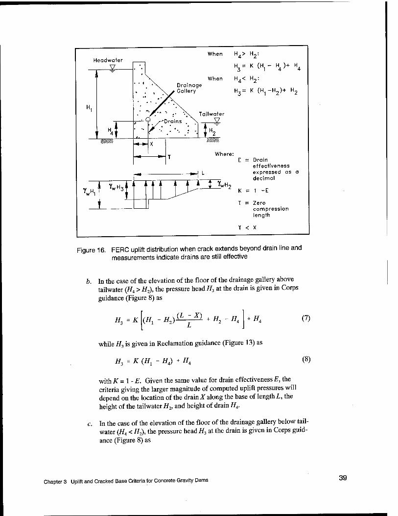
The uplift distributions assumed are the same as those presented in Figures 7, 8, 9, and 10 of this publication. In addition, where piezometric readings indicate that uplift reduction is occurring even in a dam that has a no-tension zone that extends downstream of the line of drains, the uplift pressure distribution shown in Figure 16 may be assumed.
3.1.4 Uplift criteria for the Corps and Reclamation
Both Federal agencies include uplift in their stability calculations. The following subsections summarize the similarities as well as differences among the uplift criteria.
3.1.4.1 No foundation drains. When foundation drains are not present or are inoperable, the distribution of uplift pressures is the same for both agencies, corresponding to the full reservoir pressure head H1 below the heel of the dam, full tailwater pressure head H2 below the toe, and with a linear variation in pressure head along the base.
3.1.4.2 Foundation drains and full base area contact. The uplift pressure distributions are slightly different between the agencies in the case of dams with foundation drains and full contact along the base. Three key factors contribute to these differences in the calculation of uplift pressures:
a. The Corps and Reclamation differ on their recommendation for the value to be assigned to drain effectiveness E. The Corps limits the value foris to 0.5 in the case of nonsite-specific uplift data while Reclamation assigns a value to E of 0.66 for new designs.
Chapter 3 Uplift and Cracked Base Criteria for Concrete Gravity Dams
Headwater
_xz
mm
When H4> H2:
H = K (H - H )+ H. 1 4
Drainage Gallery
When H4< H2:
H3= K (H1-H2)+ H2
Tailwater ■O --Drains . X V
-^— T» mm
Where:
Vt
iL
,f ZZ\^^ T
E = Drain effectiveness expressed as a decimal
= 1 -E
T = Zero compression length
T < X
Figure 16. FERC uplift distribution when crack extends beyond drain line and measurements indicate drains are still effective
b. In the case of the elevation of the floor of the drainage gallery above tailwater (#4 > H2), the pressure head H3 at the drain is given in Corps guidance (Figure 8) as
//, = K {Hx - //2)^T^ + H2 - HA + HA (7)
while H3 is given in Reclamation guidance (Figure 13) as
tf3 =K{H, - H4) + H4 (8)
withK=\-E. Given the same value for drain effectivenessE, the criteria giving the larger magnitude of computed uplift pressures will depend on the location of the drain X along the base of length L, the height of the tailwater H2, and height of drain H4.
c. In the case of the elevation of the floor of the drainage gallery below tail- water (#4 < H2), the pressure head H3 at the drain is given in Corps guid- ance (Figure 8) as
Chapter 3 Uplift and Cracked Base Criteria for Concrete Gravity Dams 39

H3 =K (Hl - H2) ikzH + H2 (9)
40
while H3 is given in Reclamation guidance (Figure 12) as
H3 =K(H1- H2) + H2 (10)
Because the Corps criterion multiplies the difference between headwater and tailwater by the term (L - X)/L, H3 will always be higher using Recla- mation criteria than Corps criteria given the same value for drain effec- tiveness E.
3.1.4.3 Foundation drains, partial base area contact, and crack ends prior to line of drains. When the crack does not extend to the line of drains, the Corps engineering design procedure allows for consideration of drain effectiveness. This contrasts with the Reclamation procedure, which assumes the drain ineffective when cracking initiates unless measurements are contrary.
3.1.4.4 Foundation drains and partial base area contact with crack extending beyond the line of drains. Uplift pressure distributions computed using the Corps and Reclamation procedures are the same when the crack extends beyond the line of drains. The drains are considered to be ineffective (E = 0) in this case, unless measurements demonstrate effectiveness. This distribution is full reservoir head (i/j) in the entire crack, then linear varying from H1 at the crack tip to tailwater (H2) at the toe.
3.2 Cracked Base Criteria
The cracked base criteria and corresponding stability calculations made according to guidance published by the Corps, by Reclamation, and by FERC are summarized in this section. Only that portion of guidance relating to an imaginary section made through the base of the dam is described.
3.2.1 Corps guidance on crack initiation/propagation
Crack initiation and propagation are based on a comparison of internal (nor- mal) stresses to the tensile capacity of the concrete, of the foundation material, and of the concrete-to-rock foundation interface region. In general, when the allowable tensile strength of the material is exceeded along the base of a gravity dam, a crack is assumed to form and propagate horizontally to the point at which the tensile stress is equal to the tensile strength. For a zero tensile strength material, this remaining uncracked section of the base is entirely in compression. New dams are to be designed with the resultant force located within the middle third of the base for usual loadings (Table 1). This corresponds to the case of full contact along the base (i.e., no cracking) when a linear base pressure
Chapter 3 Uplift and Cracked Base Criteria for Concrete Gravity Dams

distribution is assumed, as shown in Figure 2. For unusual and extreme loadings, dam stability must also be maintained; however, Table 1 shows that criteria for resultant location are relaxed compared with that used for a usual loading. Thus, cracking is permissible for unusual and extreme loadings while controlling dam stability using the Table 1 criteria.
The stability analysis, as described in Chapter 2, usually begins by assuming full contact along the base and assigning the appropriate distribution of uplift pressures (i.e., Figure 7 through Figure 9). Once cracking is indicated, the stabil- ity calculations are repeated for the cracked section with either the Figure 10 or Figure 11 uplift pressure distribution. In general, cracking along the base of a hydraulic structure increases the demand on the structure because of the increased uplift pressure force being applied along the base. Recall that Corps criteria apply full hydrostatic pore-water pressures within the cracked region. The set of calculations are repeated until there is no additional change in computed length of crack. Sample calculations are provided in Appendix C.
3.2.2 Reclamation guidance on crack initiation
Reclamation criteria for cracking within concrete for dams are provided in this section. Additional details regarding the equations used in these calculations are given in Appendix B.
In general, when the allowable concrete tensile strength (which is expressed by means of a minimum compressive stress ozu in the Reclamation cracking criteria) is exceeded, a crack is assumed to form and propagate horizontally to the point of zero effective normal stress, leaving the remaining uncracked section entirely in compression as explained in Appendix B. New dams should be designed not to crack for all static loading combinations; however, cracking is permissible for earthquake loading if it can be shown that stress and stability criteria are satisfied during and after the earthquake event. It is permitted for analyses to indicate that cracking is likely for existing dams, for the condition of maximum water surface with drains inoperative, as long as it can be shown that stress and stability criteria are satisfied. Once cracking is indicated, a cracked- section analysis is necessary. This involves estimating the potential penetration of a horizontal crack from the upstream face, and then computing the stress distribution and shear-friction safety factor along the uncracked portion.
Reclamation uses the following simplified equation for the minimum allowable compressive (vertical) stress at the upstream face (oZI) from uplift forces to determine crack initiation:
pwh ft s
(4)
GZ„ is equal to the absolute value of the stress at the upstream face induced from uplift forces minus the allowable tensile stress. om is the equivalent uplift stress
Chapter 3 Uplift and Cracked Base Criteria for Concrete Gravity Dams 41

when the tensile strength of concrete/, is zero. The minimum allowable compressive stress, by definition, is the minimum allowable total stress (computed without uplift). Recall that the smallest total stress, designated as (oz)m,n, is computed below the upstream face when the Figure 4 linear base pressure distribution is assumed. If the total stress (designated o2in Figure 4) is a compressive stress larger than ozu, then there is compression at this location. Otherwise, a crack is assumed to form at this point along the base (i.e., when
(°z)m,„ < °zu)-
The first term in Equation 4 contains a drain reduction factor/? which equals 1.0 for a dam without drains and without tailwater (H2 = 0) and equals 0.4 for a dam with drains and without tailwater (H2 = 0). A value of 0.4 represents drains being at about a distance of 5 percent H1 from the heel, spaced at 10-ft (3.05-m) centers across the canyon, at least 3 in. (76 mm) in diameter. All other conditions require an adjustment top as shown in Appendix B. Uplift measurements made on existing Reclamation dams with foundation drains having these characteristics have been shown to have a drain effectiveness of 66 percent (E = 0.66). Any other conditions produce different values of/?.
Figures 17 and 18 depict the background for the drain factor/? equal to 1.0 and/? equal to 0.4, respectively. Figure 18 shows that the drain factor/? equal to 0.4 reflects the transformation of the actual distribution of uplift pressures to a linear distribution (Figure 18b), with a second transformation made to a triangular uplift pressure distribution (Figure 18c). Recall that the Figure 18a uplift pressure distribution with a drain effectiveness E equal to 0.66 is based on a compilation of uplift profiles from many existing Reclamation dams. The Figure 18 uplift pressure distribution is applicable only to dams that satisfy Reclamation's spacing, sizing, and location of drains, given in the previous paragraph.
Figure 19 outlines the calculations made to determine the value to be assigned to drain factor/? in all other cases (e.g., when tailwater is present and H2 is not equal to zero).
The value assigned to drain factor/? is calculated using the transformed tri- angular uplift pressure distributions given in Figures 17 through 19. The second transformation to a triangular uplift pressure distribution is an exact transforma- tion for the Figure 17 case of no drains and no tailwater but is an approximate transformation in all other cases, such as those represented by Figures 18 and 19.
Sample calculations showing Reclamation crack initiation methodology are provided in Appendices D and E.
3.2.3 Reclamation guidance on crack propagation
The stability analysis, as described in Chapter 2, usually begins by assuming full contact along the base and assigning the appropriate distribution of uplift pressures (i.e., Figure 12 or Figure 13). Once cracking is indicated according to
42 Chapter 3 Uplift and Cracked Base Criteria for Concrete Gravity Dams

No Drains, No Tailwater Drain Effectiveness E = 0
Pool, H,
"H1 = YwH1
Tailwater, H- = 0
UH2=YwH2= 0
Moment about (£
*-i
a) Uplift Profile (Pore water pressures)
Moment about (£_
Mu = ^ eu
u_linear
b) Linear Uplift Profile
Eqv_Uplift_heel
= PYwHi
ci = 0 Eqv_Uplift_toe
u_eqv
c) Triangular Equivalent Uplift Profile
Eqv_Uplift_heel u_hnear
u_lmear
y H w' '1
Figure 17. Background for the Reclamation drain factor p set equal to 1.0
Chapter 3 Uplift and Cracked Base Criteria for Concrete Gravity Dams 43
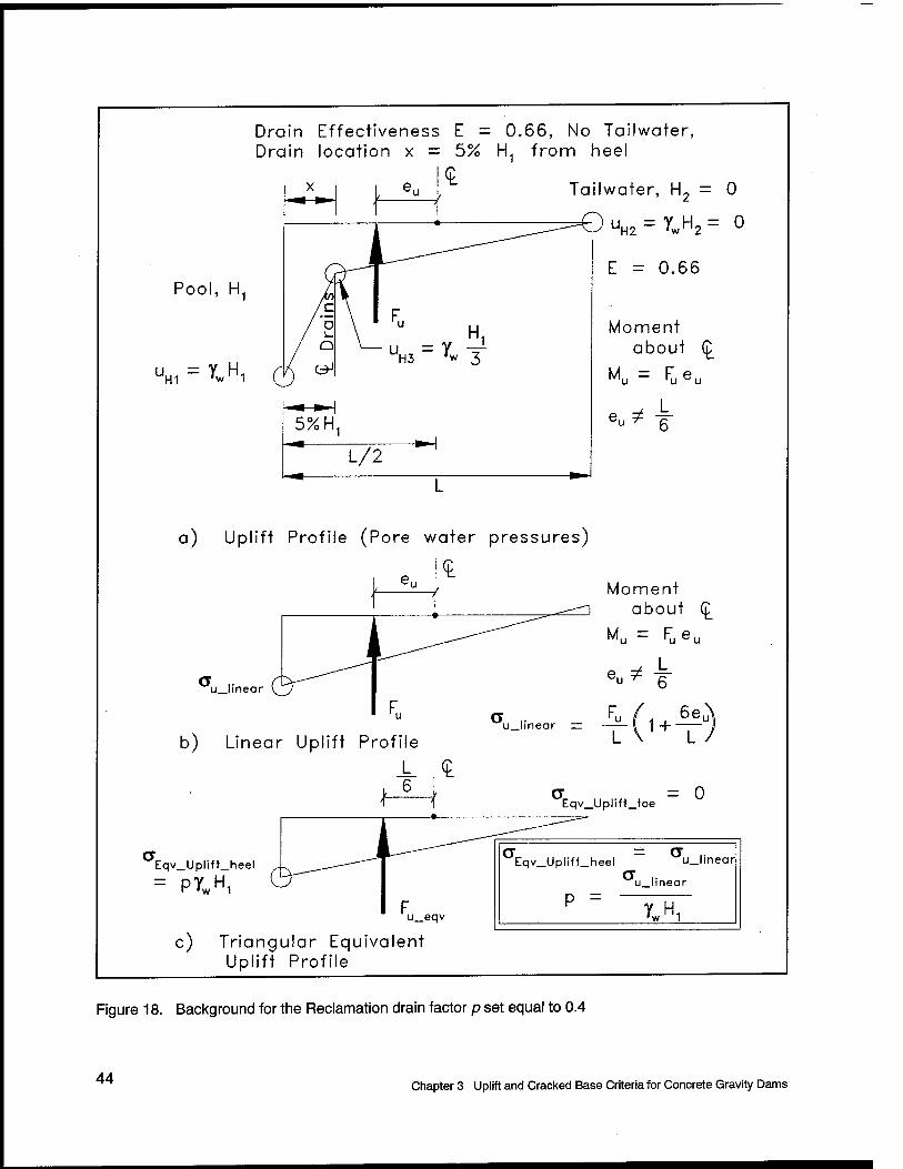
Drain Effectiveness E = 0.66, No Tailwater, Drain location x = 5% H1 from heel
Tailwater, H2 = 0
" UH2=YWH2= 0
Pool, H1
"m^wH,
E = 0.66
Moment about (£
Mu = Fueu
a) Uplift Profile (Pore water pressures)
It Moment
about (£
Mu = Fueu
u_hnear
b) Linear Uplift Profile
a = 0 Eqv_Uplift_toe
Eqv_Uplift_heel
= PYwHi
u_eqv
c) Triangular Equivalent Uplift Profile
<T — a .. Eqv_Uplift_heel u_linear
P = ulinear
y H1 •w 1
Figure 18. Background for the Reclamation drain factor p set equal to 0.4
44 Chapter 3 Uplift and Cracked Base Criteria for Concrete Gravity Dams

Drain Effectiveness E, Tailwater, Drain location x from heel
Pool, H1
H1 'w 1
Tailwater, H,
UH3 = Yw H3
L/2
UH2 = XvH2
Moment about (£
^u = lv,eu
eu^ L
a) Uplift Profile (Pore water pressures)
u_linear
u_linear —
b) Linear Uplift Profile
Moment about (£
Mu = Fueu
Fu ^ 1 _l_ 6—u
Eqv_Uplift_heel
= PYwHi
u_eqv
u_linear
u_Mnear
•w 1
c) Triangular Equivalent Uplift Profile
Figure 19. Calculations made for the Reclamation drain factor p with full base contact and tailwater
Chapter 3 Uplift and Cracked Base Criteria for Concrete Gravity Dams 45

the procedures outlined in section 3.2.2, the stability calculations are repeated for the cracked section with either the Figure 14 or Figure 15 uplift pressure distribution. In general, cracking along the base of a hydraulic structure increases the demand on the structure because of the increased uplift pressure force being applied along the base. Recall that the Reclamation procedure is to apply full hydrostatic pore-water pressures within the cracked region and to assume that the drains are ineffective (E = 0) unless measurements are taken. The set of calculations are repeated until there is no additional change in computed length of crack.
Once it has been determined that a crack will form below the heel of the dam, the length of cracking along the base is computed. These iterative calculations are concluded once the equivalent effective stress at the crack tip is computed to be equal to zero (or equal to the allowable tensile strength for the material). The crack initiation criteria of the minimum allowable compressive stress am is not used in the calculation of crack length. Uplift pressures are included in the gravity method of analysis to compute the linear effective stress distribution and the corresponding effective normal force N along the uncracked portion of the base of the dam. These calculations for a cracked base are the same as those used by the Corps (summarized in Figures 1 and 2). Sample calculations showing Reclamation crack propagation methodology are provided in the set of calculations described in Appendices D and E.
3.2.4 FERC guidance on crack initiation and propagation
FERC requires the assumption of zero tensile strength of the dam/foundation interface. This implies that whenever an analysis indicates a tensile stress normal to the interface, a crack must be assumed to initiate and to propagate to the point where only compressive normal effective stresses remain. This requirement is independent of the analysis procedure used. The zero tension criterion is enforced on finite element analysis in the same way that it is on conventional gravity analysis. If fracture mechanics is employed, this requirement translates to a plane of zero fracture toughness.
Horizontal planes within the body of the dam are not evaluated for stability or crack propagation unless cracking has actually been observed. If there are actual cracks in the body of the dam that appear to be throughgoing, uplift distributions are assumed to be of the same type as those applied to the dam foundation interface. Cracks observed on the downstream side of the dam shall be assumed to be throughgoing. Cracks that originate on the upstream face but are not throughgoing are assumed to be pressurized with full reservoir pressure.
The zero tension criterion applies only to the sliding plane being considered. Maximum principal tensions in concrete in general are limited to those values shown in Table 3.
46 Chapter 3 Uplift and Cracked Base Criteria for Concrete Gravity Dams

3.2.5 Crack initiation/propagation for the Corps and Reclamation
Both Federal agencies define the engineering procedures to be followed when the calculations show a potential for cracking along the base of the dam in the stability calculations. The following subsections summarize the similarities as well as differences between the two agencies.
3.2.5.1 Crack initiation. Both agencies recognize in their guidance that the area with the greatest potential for cracking to initiate is below the heel of the dam. However, the Corps and Reclamation differ on the calculations made to determine when cracking initiates. It is useful to first review the calculations made by the agencies to determine crack initiation.
The Corps establishes the potential for cracking along the base by comparing the minimum value of effective normal stress P'min against the tensile capacity for the region in question (Figure 2). Cracking initiates below the heel of the dam if P^in is tensile and exceeds the tensile capacity of the material. The tensile capacity along the base of a gravity dam section is often set equal to zero in these calculations. To calculate the distribution of effective stresses along the base, the normal component of the resultant force R is converted to a linear distribution of effective base pressure using the equations given in Figure 2. Recall that uplift pressures are included in the calculation of R, as depicted in Figure 1.
Reclamation establishes the potential for cracking along the base by comparing the induced total stress az at the heel using the equations given in Figure 4, with ozu. Recall that azu is calculated by:
o2u = pwh - V (4)
Recall that/, is the tensile strength of the material and 5 is the safety factor. The term pwh represents the transformed uplift pressure below the heel of the dam, as shown in Figures 17 through 19. Recall that the resultant uplift force and its point of application are the same for both the actual and transformed (triangular) uplift pressure distributions in these calculations only for the case of no tailwater and no drains (Figure 17). Cracking initiates below the heel of the dam when the compressive stress az does not achieve the minimum compressive stress azu
value.
Reclamation crack initiation criteria represent the "demand" below the heel of the dam by a transformed uplift pressure. Figures 18 and 19 show that this transformed uplift pressure below the heel can be less than the actual uplift pressure when drains are present. Comparisons of crack initiation calculations made between the Corps guidance and Reclamation guidance indicate the following:
Chapter 3 Uplift and Cracked Base Criteria for Concrete Gravity Dams 47
a. The two procedures produce the same results when all the applied forces on the dam section are identical.
b. The analytic methodologies are different. The Corps calculates effective base pressures and compares the location of the resultant (effective) force. Reclamation calculates the total stress at the heel without uplift and compares this stress to an equivalent uplift stress om at the heel.
3.2.5.2 Crack propagation. The length of cracking along the base is com- puted according to both Corps and Reclamation criteria using iterative calcula- tions to determine the length of crack resulting in an effective stress at the crack tip of zero (or equal to the allowable tensile strength for the material). The methods used by the Corps and Reclamation compute the same crack length when the uplift profiles are the same. However, differences may exist in the computed length of crack because of differences in the uplift pressure distribution being used in these calculations. For example, Reclamation guidance does not allow for drain effectiveness once a crack has formed while Corps guidance allows for consideration of drain effectiveness so long as the crack does not extend to or beyond the drain.
3.2.6 Crack initiation/propagation for the Corps and FERC
FERC makes the same assumptions as does the Corps. The FERC method will yield identical results to the Corps method.
48 Chapter 3 Uplift and Cracked Base Criteria for Concrete Gravity Dams

4 Calculation of the Length of Cracking Along the Concrete Gravity Dam-to- Foundation Interface by Conventional Equilibrium Analyses and the Corps Uplift Pressure Distribution
This chapter summarizes the calculation of the stability of an example concrete gravity dam section using the Corps, Reclamation, and FERC engineering procedures. The uplift water pressure distribution applied in all three sets of calculations is stipulated as that developed in accordance with guidance published in EM 1110-2-2200 used to design concrete gravity dams. Key aspects of this guidance are summarized in section 3.1.1 in Chapter 3 of this report. The objective of these calculations is to compare the engineering methodologies used by the three agencies to calculate crack potential and crack extent.
4.1 Example Concrete Gravity Dam Problem
Figure 20 shows the example concrete gravity dam section used in the stability calculations made according to Corps, Reclamation, and FERC stability criteria. This example problem is a concrete gravity dam with the following dimensions, unit weights, loads, and drainage:
Dam height Hd = 100 ft (30.48 m) Base width L = 75 ft (22.86 m) Crest width d = 5 ft (1.52 m) Downstream slope (run:rise) = 0.7:1 Datum is the elevation of the dam to rock foundation interface
Chapter 4 Calculation of the Length of Cracking Using Corps Uplift Pressure Distribution 49

Reservoir
•4 <«
Crest width d = 5 ft
M—
* * 4 \
. -* * \ Slope 0.7:1 o o
"^ Dam o \ T • \ II
Drain •o
1 4 /\ Gallery
^ / *
^ \ \ Tailv
E o Q r
u * ^ * , 4 ,
4 \
1
He< 1
3l
J
Base width L = 75 ft To
Tailwater depth H. 5 ft
V
Drain statis tics
Effectiveness E = : 0.25
Distance from heel xd = = 10 ft
Height a bove base
H4 = = 10 ft
uE = 10 = YW(10 ft)
E = 1.0
Material prope rties
Concrete dens ity 150 p cf
Water d ensity 62.5 pcf
UH2 ~ Yw H2
312.5 psf
= Yw H3 = 4,250 psf
uE = 0 = Yw (87.33 ft)
uH1 = Yw H1 = 6,250 psf
H, = 68 ft by Corps Criteria (from Figure 8)
Figure 20. Gravity dam example problem using Corps uplift criteria with full base contact (1 ft: 0.305 m, 1 psf = 47.88 Pa, 1 pcf =16.018 kg/m3)
50 Chapter 4 Calculation of the Length of Cracking Using Corps Uplift Pressure Distribution

Reservoir height H1 = 100 ft (30.48 m) Tailwater height H2 = 5 ft (1.52 m) Drain effectiveness E = 0.25 Distance between heel and center line of drainsxd= 10 ft (3.05 m) Drain height above base H4 = 10 ft (3.05 m) Concrete density = 150 pcf (2,402.77 kg/m3) Unit weight of water = 62.5 pcf (1,001.15 kg/m3) Tensile capacity = 0 ksf (0 kPa)
Figure 20 also shows uplift pressure distribution and pressure head at the drain H3 (68 ft (20.73 m)) used in the initial stability calculations assuming full base contact. A value of H3 equal to 68 ft (20.73 m) corresponds to a drain effectiveness of 25 percent (E = 0.25). This distribution of uplift pressure is calculated using the Corps relationship given in Figure 8 for full base contact and the elevation of the floor of the drainage gallery above the elevation of tailwater (H4 > H2). The Corps concept of drain effectiveness is explained in Appendix A of this report using Figure A.1 (and with crack length T set equal to zero in cited equations).
All three agencies start their stability calculations of gravity dam section(s) assuming full base area contact (i.e., uncracked base). The Figure 20 uplift pressure distribution is used in each of the initial stability calculations cited in this chapter.
4.2 Stability Calculations Made Using Corps Criteria
This section summarizes the stability calculations made of the Figure 20 gravity dam section using the Corps engineering procedure. This engineering procedure, given in EM 1110-2-2200, is outlined in section 2.1 in Chapter 2 of this report. Figure 21 summarizes the results of the initial stability calculation for the gravity dam section assuming full base area contact. Appendix C gives the complete series of calculations. The results given in Figure 21 indicate that a crack will develop at the heel of the interface because the resultant force of the effective normal pressure distribution TV acts at a point located outside the middle third of the dam base. Recall that in the Corps procedure, the uplift pressure force C/is included in the equilibrium equations used to calculate N and its point of action (designated eN and measured from the center line of the base of the dam).
Once cracking is indicated, the stability calculations are repeated using the Corps' Figure 10 cracked-section uplift pressure distribution. Details regarding these calculations are given in Appendix C. The calculations show that cracking along the base of the dam increases the demand on the structure compared with results from the previous set of calculations (Figure 21) because of the increased uplift pressure force being applied along the base. This increased load is attrib- uted to Corps criteria requiring the application of full hydrostatic pore-water
Chapter 4 Calculation of the Length of Cracking Using Corps Uplift Pressure Distribution 51

V
H, = 100 ft
H Pool
Hpool
Heel
U
i N
I. J. J
37.5 ft VT
L = 75 ft
Figure 21a. Initial stability calculation of a gravity dam section with full base area contact and following Corps criteria (1 ft = 0.305 m, 1 kip = 4.448 kN, 1 kip-ft = 1.356 kN-m) (Continued)
52 Chapter 4 Calculation of the Length of Cracking Using Corps Uplift Pressure Distribution
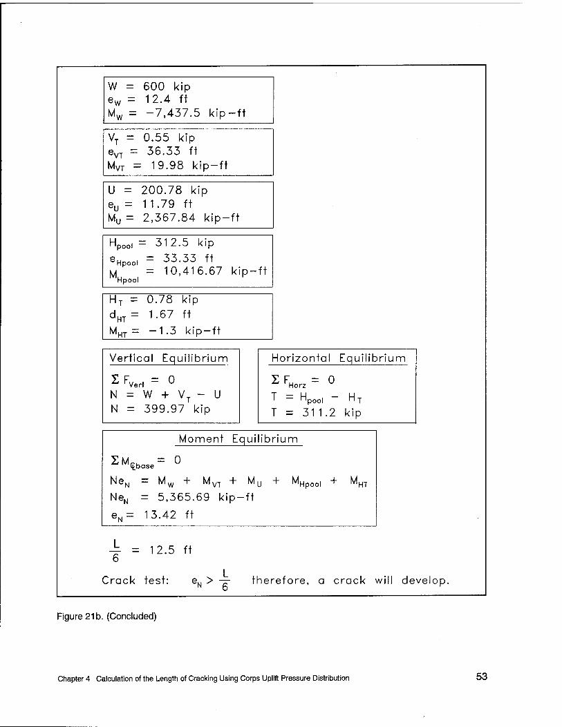
W = 600 kip ew = 12.4 ft Mw = -7,437.5 kip-ft
vT 0.55 k P eVT
— 36.33 ft MVT 19.98 W P- -ft
U = 200.78 kip eu = 11.79 ft Mu = 2,367.84 kip-ft
l_l npool = 312.5 k 'P eHpool
M
= 33.33 ft = 10,416 .67 k P" -ft Hpool
HT — 0.78 kip
dHT = 1.67 ft
MHT = -1.3 kip- -ft
Vertical Equi lib rium
2 FVer, = 0 N = W + V N = 399.97
r k
- U
P
Horizonte I Equi lib rium
2 FHorz =
T = Hpool T = 31 1
0
.2 HT
kip
Moment Equilibrium
ZM<Lba,.= ° NeN = Mw + MVT + My + MHpoo, + MHT
NeN = 5,365.69 kip-ft
eN= 13.42 ft
L = 12.5 ft
Crack test: eN > -p- therefore, a crack will develop.
Figure 21b. (Concluded)
Chapter 4 Calculation of the Length of Cracking Using Corps Uplift Pressure Distribution 53
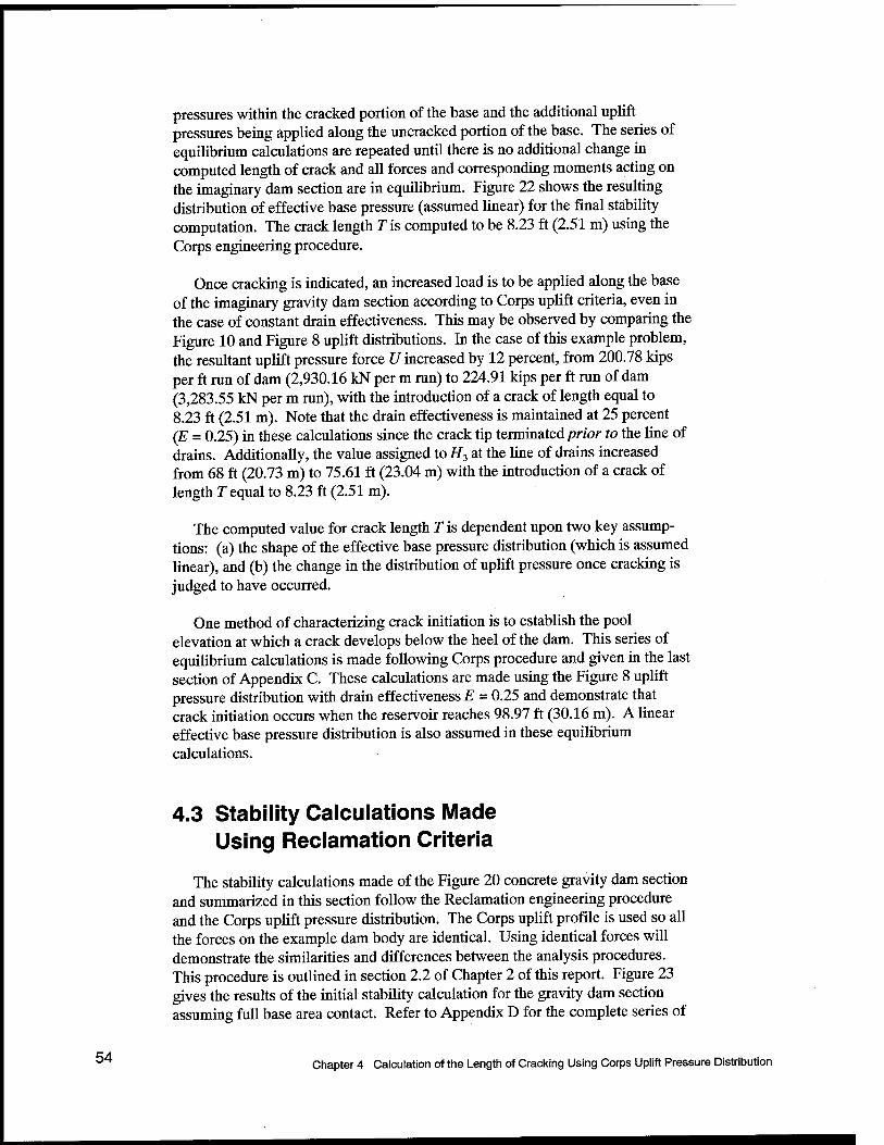
pressures within the cracked portion of the base and the additional uplift pressures being applied along the uncracked portion of the base. The series of equilibrium calculations are repeated until there is no additional change in computed length of crack and all forces and corresponding moments acting on the imaginary dam section are in equilibrium. Figure 22 shows the resulting distribution of effective base pressure (assumed linear) for the final stability computation. The crack length T is computed to be 8.23 ft (2.51 m) using the Corps engineering procedure.
Once cracking is indicated, an increased load is to be applied along the base of the imaginary gravity dam section according to Corps uplift criteria, even in the case of constant drain effectiveness. This may be observed by comparing the Figure 10 and Figure 8 uplift distributions. In the case of this example problem, the resultant uplift pressure force U increased by 12 percent, from 200.78 kips per ft run of dam (2,930.16 kN per m run) to 224.91 kips per ft run of dam (3,283.55 kN per m run), with the introduction of a crack of length equal to 8.23 ft (2.51 m). Note that the drain effectiveness is maintained at 25 percent (E = 0.25) in these calculations since the crack tip terminated prior to the line of drains. Additionally, the value assigned to H3 at the line of drains increased from 68 ft (20.73 m) to 75.61 ft (23.04 m) with the introduction of a crack of length T equal to 8.23 ft (2.51 m).
The computed value for crack length T is dependent upon two key assump- tions: (a) the shape of the effective base pressure distribution (which is assumed linear), and (b) the change in the distribution of uplift pressure once cracking is judged to have occurred.
One method of characterizing crack initiation is to establish the pool elevation at which a crack develops below the heel of the dam. This series of equilibrium calculations is made following Corps procedure and given in the last section of Appendix C. These calculations are made using the Figure 8 uplift pressure distribution with drain effectiveness E = 0.25 and demonstrate that crack initiation occurs when the reservoir reaches 98.97 ft (30.16 m). A linear effective base pressure distribution is also assumed in these equilibrium calculations.
4.3 Stability Calculations Made Using Reclamation Criteria
The stability calculations made of the Figure 20 concrete gravity dam section and summarized in this section follow the Reclamation engineering procedure and the Corps uplift pressure distribution. The Corps uplift profile is used so all the forces on the example dam body are identical. Using identical forces will demonstrate the similarities and differences between the analysis procedures. This procedure is outlined in section 2.2 of Chapter 2 of this report. Figure 23 gives the results of the initial stability calculation for the gravity dam section assuming full base area contact. Refer to Appendix D for the complete series of
54 Chapter 4 Calculation of the Length of Cracking Using Corps Uplift Pressure Distribution

V
Hpool
Heel t-
37.5 ft
Uplift
UHI= 'wHi = yw(ioo ft) = 6.25 ksf
uH2= YWH2= Yw(5 ft) = 0.31 ksf
At Droin UH3= YwH3= yw (75.61 ft) = 4.25 ksf
H, by Corps criteria given in Figure 10
U = 224.9 kip e„= 16.25 ft
Crack Length T = 8.23 ft
*.
Effective Base Pressure
N. 1 \ , V t'\
B = 66.77 ft
:
N = 375.65 kip eu = 15.24 ft
L = 75 ft
Figure 22. Final stability calculation of a gravity dam with crack length T= 8.23 ft following Corps procedures (1 ft = 0.305 m, 1 ksf = 47.88 kPa, 1 kip = 4.448 kN)
Chapter 4 Calculation of the Length of Cracking Using Corps Uplift Pressure Distribution 55

V
H, = 100 ft
H Pool
Hpool
Heel
N total
37.5 ft 'VT
L = 75 ft
1HJ
Figure 23a. Initial stability calculation of a gravity dam with full base area contact following Reclamation procedures (1 ft = 0.305 m, 1 kip = 4.448 kN, 1 kip-ft = 1.356 kN-m, 1 psi = 6.894 kPa, 1 pcf = 16.018 kg/m3, 1 psf = 47.88 Pa) (Sheet 1 of 4)
56 Chapter 4 Calculation of the Length of Cracking Using Corps Uplift Pressure Distribution

w = 600 kip ew = 12.4 ft Mw = -7,437.5 kip - -ft
vT ■ = 0.55 k' P eVT = 36.33 ft
MVT = 19.98 kip- -ft
■■pool = 312.5 kip
eHpool
M., ,
= 33.33 ft = 10,416.67 k P- -ft
Hpool
HT = 0.78 kip dHT = 1.67 ft
MHT = -1.3 kip- -ft
Vertical Equilibrium
2 FVert = 0 Ntota, = w + vT
N|ota| = 600.55 kip
Horizonte I Equi ibrium
2FH( >rz 0
T = u npool HT
T = 31 1 .2 kip
2 M<tbase
Moment Equi ibrium
= 0
^lotaieN = Mw + M *T + MHpool + MHT
NlotaleN = 2997.73 kip- -ft
®N = 4.99 ft
Figure 23b. (Sheet 2 of 4)
Chapter 4 Calculation of the Length of Cracking Using Corps Uplift Pressure Distribution 57
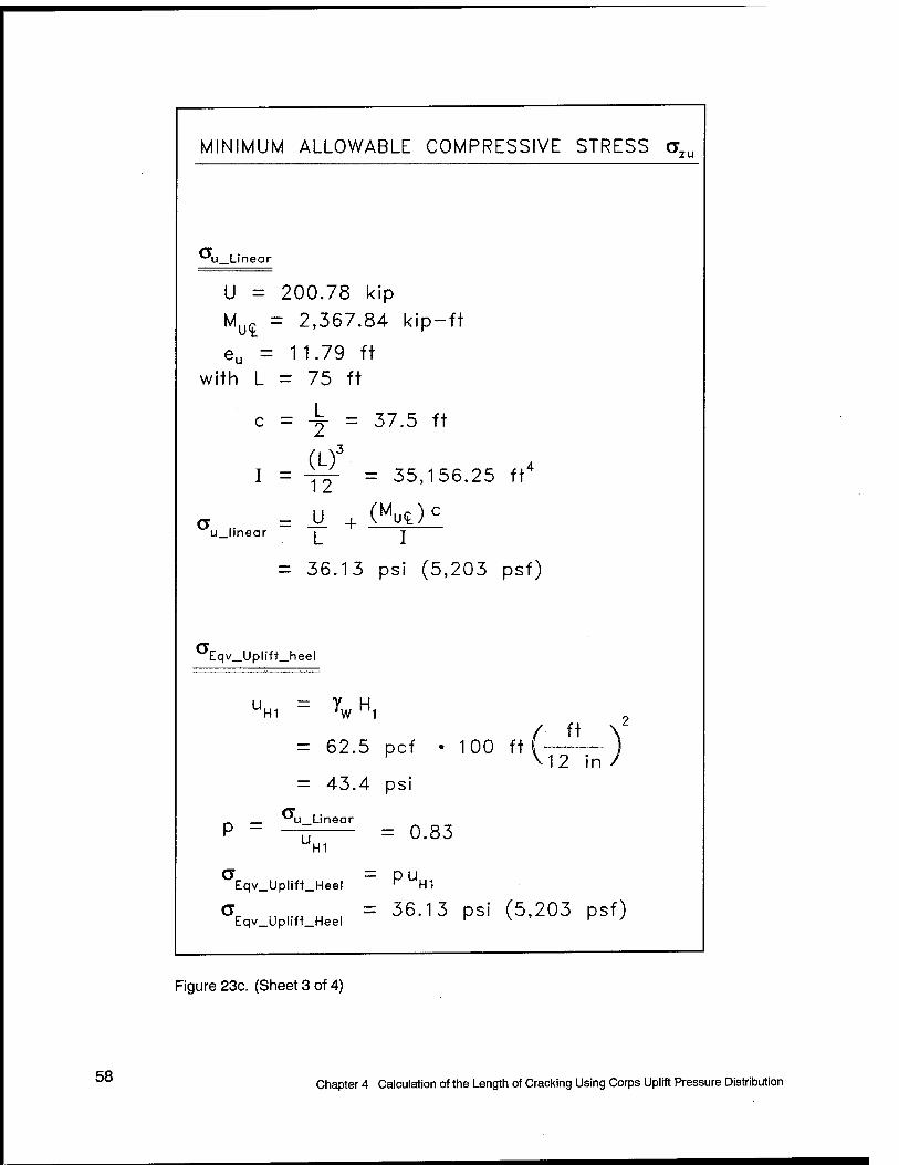
MINIMUM ALLOWABLE COMPRESSIVE STRESS ' a,
"uLinear
U = 200.78 kip Muq = 2,367.84 kip-ft
eu = 11.79 ft with L = 75 ft
' c = -j = 37.5 ft
I = yf- = 35,156.25 ft4
a = V_ + (MU<E)C
u_linear i T
36.13 psi (5,203 psf)
Eqv_Uplift_beel
UH1 ~ \ H1
= 62.5 pcf • 100 ft( ) K \12 in / = 43.4 psi
P = "u_Linear
U H1
Eqv_Uplift_Heel
= 0.83
PUH1
ar n r« u , = 36'13 PS' (5,203 psf) Eqv_Uphn_Heel ' N ' '
Figure 23c. (Sheet 3 of 4)
58 Chapter 4 Calculation of the Length of Cracking Using Corps Uplift Pressure Distribution
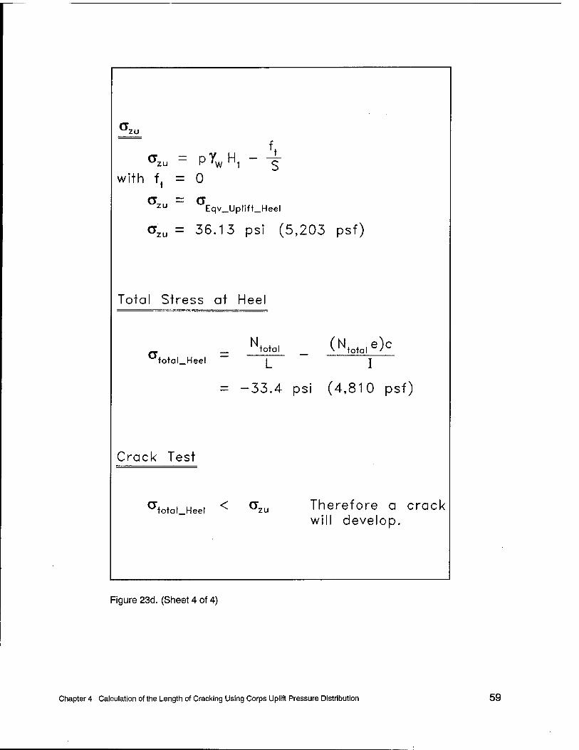
'zu
zu - PYW H1 ~ 'W 1
with f^ =
<*zu =
er,.. = zu
0
o Eqv_Uplift_Heel
36.13 psi (5,203 psf)
Total Stress at Heel
N total (Ntn+n,e)c total_Heel L I
-33.4 psi (4,810 psf)
Crack Test
total_Heel < a zu Therefore a crack will develop.
Figure 23d. (Sheet 4 of 4)
Chapter 4 Calculation of the Length of Cracking Using Corps Uplift Pressure Distribution 59

calculations. The results given in Figure 23 indicate that a crack will develop at the heel of the interface because the magnitude of the total stress below the heel a total heelis less than the minimum allowable compressive stress o^. Recall that in these calculations, the uplift pressure force C/is included in the calculation of the minimum allowable compressive stress om and not in the calculation of ototalJieel. Figure 24 shows the use of the Figure 8 Corps uplift criteria in this set of calculations to determine the value for aa (oEqv_Upli{t_heelwith the tensile capacity/, equal to zero). The Reclamation drain factor/7 is computed equal to 0.83 for the case of full contact, drain effectiveness E equal to 0.25, and tailwater equal to 5 ft (1.52 m). A composite of the resulting stress distributions is given in Figure 25 in this case in which full base contact is assumed.
Once cracking is indicated, the stability calculations are repeated for the cracked section with the Corps Figure 10 uplift pressure distribution. The Corps uplift profile is used so all the forces on the example dam body are identical. Using identical forces will demonstrate the similarities and differences between the analysis procedures. The nature of these calculations made for a cracked base changes from those used to determine crack initiation. These calculations become essentially an effective stress-based procedure like that used by the Corps. Crack propagation is determined by comparing the minimum effective base pressures against the tensile strength for the material. The tensile strength is set equal to zero along the interface in this problem. The resultant uplift pressure force U is included in the equilibrium calculations to obtain the effective base pressure force N. The forces acting on the dam section being analyzed are the same as those used in the Corps engineering procedure shown in Figure 22. Reclamation assumes a linear effective base pressure distribution in these equilibrium calculations to determine crack length T. Detailed calculations are given in Appendix D. A composite of the resulting stress distributions is given in Figure 26. This series of equilibrium calculations results in a computed crack length T equal to 8.23 ft (2.51 m), a result consistent with the calculations made following Corps procedures.
Figure 26 shows that the Figure 10 based, cracked-base uplift profile, desig- nated "Uplift profile" in this figure, is transformed to a "Linear uplift profile" in the Reclamation procedure. However, this transformation does not introduce a discrepancy in results (i.e., effective base pressure and corresponding resultant effective normal force) compared with that computed using the Corps procedure because (a) the equations of force and moment equilibrium are used prior to assigning a corresponding linear base pressure distribution to the resultant normal force in the cracked base stability analysis, and (b) the "Linear uplift profile" distribution maintains the same magnitude resultant uplift force and point of action along the base as the original "Uplift profile." This compatibility of results between the two engineering procedures is true only for the cracked base analysis with a common "original" uplift pressure distribution.
A second series of equilibrium calculations made following the Reclamation engineering procedure and Corps uplift distribution established that crack initia- tion occurs when the reservoir reaches 98.97 ft (30.16 m, Appendix D). These
60 Chapter 4 Calculation of the Length of Cracking Using Corps Uplift Pressure Distribution

Drain Effectiveness E = 0.25, Tailwater Drain location xd = 10 ft from heel, L = 75fi
62.5 pcf
Pool, H,
V) c D
Q
um = YWH1 C / = 6,250 psf
(43.4 psi)
Tailwater, H2 = 5 ft
H3 = 68 ft UH3 = YWH3
= 4,250 psf (29.51 psi)
UH2 = *,H2
uH2 = 312.5 psf (2.17 psi)
Moment about (£
M. = F e
?„ = 200.78 ki P Mu 2,367.84 k P- -ft
eu ~ 11.79 ft
a) Uplift Profile (Pore water pressures)
151 psf (1.05 psi)
u_ltnear
Moment about (£
Mu = Fueu
u_lineor
b) Linear Uplift Profile
= 5,203 psf (36.13 psi)
= 12.5 ft
Eqv_Uplift_heel
= P?wH,
Eqv_Uplift_foe
c) Triangular Equivalent Uplift Profile
a = cr ,. Eqv_UplHt_heel u_hnear
u_hnear p = —:7-rr- = 0.83
Eqv_Uplift_heel = 5,203 psf
(36.13 psi)
Figure 24. Calculations made for the Reclamation drain factor p with full base contact, E = 0.25 and tailwater at 5 ft (1 ft = 0.305 m, 1 kip = 4.448 kN, 1 kip-ft = 1.356 kN-m, 1 pcf =16.018 kg/m3, 1 psf = 47.88 Pa, 1 psi = 6.894 kPa)
Chapter 4 Calculation of the Length of Cracking Using Corps Uplift Pressure Distribution 61

uH1 = YWH, = 43.4 psi
L<TEqv_Uplif1_heelJ
effec)ive_Heel
= 2.73 psi
'-'»otal_Heel —
— 33.4 psi
a = CT Eqv_Uplift_heel u_linear
<5u_..neor= 36'13 PS' azu _ °tqv_Upllft_heel
= 36.13 psi
\ Equivalent Uplift Profile (Figure 24.c)
Effective stress (w/ uplift) -
— Uplift profiles
— Stresses along base (base pressures)
-77.81 psi-
Crack Test
°Wal_Heel < azu Therefore a crack will develop.
Figure 25. Minimum allowable compressive stress ozu according to Reclamation criteria and assuming full base contact (1 psi = 6.894 kPa)
62 Chapter 4 Calculation of the Length of Cracking Using Corps Uplift Pressure Distribution

L = 75 ft
57.54 psi
Yw (75.61 ft) psi
Linear uplift profile
Crack tip
c o
'i/i </> a> i_ Q. E o u
total -57,54 psi
Effective Stress at crack tip ^effective = 0 psi
Effective stress (w/ uplift)
\ \
Total stress (w/o uplift)
\
\
Uplift profiles
Stresses along base (base pressures)
2.17 psi
-10.76 psi
-67.38 psi
-78.14 psi
Figure 26. Crack length T= 8.23 ft according to Reclamation criteria (1 ft = 0.305 m, 1 psi = 6.894 kPa)
Chapter 4 Calculation of the Length of Cracking Using Corps Uplift Pressure Distribution 63

calculations show the engineering procedures to determine crack initiation. Fig- ure 27 summarizes the resulting stress distributions along the base of the dam for a reservoir elevation equal to 98.97 ft (30.16 m). Note that the value for total stress below the heel amal_heel is equal in magnitude and opposite in sign to the minimum allowable compressive stress om. These calculations are made using the Corps Figure 8 uplift pressure distribution with drain effectiveness E equal to 0.25. This reservoir elevation is consistent with calculations made following the Corps engineering procedure. A linear total base pressure distribution is assumed in these equilibrium calculations.
4.4 Stability Calculations Made Using FERC Criteria
Stability calculations made of the Figure 20 concrete gravity dam section using the FERC engineering procedures were conducted using the FERC uplift distributions but with a unit weight of water set equal to the FERC standard value of 62.4 pcf (999.5 kg/m3) (Appendix F). The predicted crack length is 7.64 ft (2.33 m). A second series of calculations (not shown) were made using the Corps uplift distribution (Figure 10) using a unit weight of water equal to 62.5 pcf (1,001.13 kg/m3). The final predicted crack length for this second series of calculations (not shown) is 8.23 ft (2.51 m) and agrees with the crack length predicted using the Corps and Reclamation procedures.
Note that the difference in computed crack length for the two sets of FERC computations is attributed to the fact that the FERC engineering procedure uses a unit weight of water that is slightly less than the value of 62.5 pcf (1,001.13 kg/m3) that is commonly used by the Corps. The uplift distributions assumed by FERC are identical to those assumed by the Corps with the exception of the case where cracking extends beyond the drains and the drains remain effective.
4.5 Conclusions
The calculations summarized in this chapter demonstrate that given the same uplift distribution, the Corps, Reclamation, and FERC engineering methodologies to calculate crack extent are the same. This is because in all three engineering procedures, force and moment equilibrium are enforced, and the same assumption is made with respect to the effective stress distribution along the base; namely, that it is linear. Additionally, because the calculated pool elevation at which a crack develops below the heel of the dam is the same for the three engineering procedures when the same uplift distribution is used in the calculations, it is reasoned that crack potential is consistent for the three engineering procedures.
64 Chapter 4 Calculation of the Length of Cracking Using Corps Uplift Pressure Distribution

uH1 = YWH, = 42.95 psi
L^qv.UplifUheelJ
effective_Heel
= 0.00 psi
"toloLHeel
35.77 psi_
Full uplift, -no tailwater, no drains
Eqv_Upllft_heel u_llnear
^.linear = 35"77 PS' 3
= 35.77 psi
CTzu — °rE:qv_Upli«_heel
Uplift profiles
Stresses along base (base pressures)
75.45 psr
Figure 27. Reservoir elevation H, = 98.97 ft resulting in ototaLHee, equal to ozu using Reclamation cirtieria (1 ft = 0.305 m, 1 psi = 6.894 kPa)
Chapter 4 Calculation of the Length of Cracking Using Corps Uplift Pressure Distribution 65

Calculation of the Length of Cracking Along the Concrete Gravity Dam-to- Foundation Interface by Conventional Equilibrium Analyses and Using Uplift Pressure Distributions According to the Guidance Employed by the Corps, Reclamation, and FERC
This chapter summarizes the calculation of the stability of an example concrete gravity dam section using the Corps, Reclamation, and FERC engineering procedures. The uplift water pressure distributions used in the analyses are assigned as stipulated in the engineering documents published by each of the three agencies. A drain effectiveness E equal to 0.25 is assigned in both of the initial stability computations, which assume full base contact. The objective of these calculations is to demonstrate the impact of the uplift distributions on the stability calculations, expressed in terms of crack potential and crack extent.
5.1 Example Concrete Gravity Dam Problem
The 100-ft- (30.48-m-) high concrete gravity dam section used in the Chapter 4 stability computations is used in this series of calculations to demonstrate the impact of the uplift distributions on the results of the stability
66 Chapter 5 Calculation of the Length of Cracking Using Uplift Pressure Distributions of Both Agencies

computations. Figure 20 shows the gravity dam section being analyzed. The dimensions, unit weights, loads, and drainage are summarized in section 4.1 of Chapter 4 of this report.
5.2 Stability Calculations Made Using the Corps Engineering Procedure and Uplift Pressure Distributions
The stability calculations made of the Figure 20 concrete gravity dam section using the Corps engineering procedure was outlined in section 4.2 of Chapter 4 of this report with detailed calculations given in Appendix C. In summary, the results of the initial stability calculation given in Figure 21 indicate that a crack will develop at the heel of the interface because the resultant force of the effective normal pressure distribution N acts at a point located outside the middle third of the dam base. Figure 20 summarizes the uplift pressure distribution used in this initial stability computation assuming full base contact. This distribution of uplift pressure is calculated using the Corps relationship given in Figure 8 for an uncracked base section.
Once cracking is indicated, the stability calculations are repeated using the Corps Figure 10 cracked-section uplift pressure distribution. The Appendix C calculations show that cracking along the base of the dam increases the demand on the structure compared with the previous set of calculations (assuming full base contact) because of the increased uplift pressure force being applied along the base. Figure 22 shows the resulting distribution of effective base pressure (assumed linear) for the final stability computation. The crack length T is com- puted to be 8.23 ft (2.51 m) using the Corps engineering procedure.
A second series of calculations made in Appendix C using the Figure 8 uplift pressure distribution with drain effectiveness E = 0.25 demonstrate that crack initiation occurs when the reservoir reaches 98.97 ft (30.16 m).
5.3 Stability Calculations Made Using the Reclamation Engineering Procedure and Uplift Pressure Distributions
The stability calculations made of the 100-ft- (30.48-m-) high concrete gravity dam section and summarized in this section follow the Reclamation engineering procedure and Reclamation uplift criteria. These calculations show the differences in uplift pressure distributions and the effect on crack initiation and crack length between the Corps and Reclamation. This procedure is summarized in section 2.2 of Chapter 2 of this report. Reclamation procedures for calculating uplift pressure distributions are summarized in section 3.1.2 of Chapter 3 of this report.
Chapter 5 Calculation of the Length of Cracking Using Uplift Pressure Distributions of Both Agencies 67
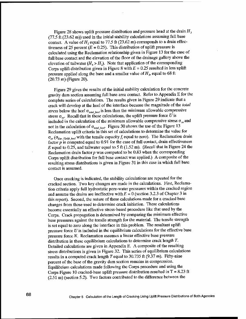
68
Figure 28 shows uplift pressure distribution and pressure head at the drain H3
(77.5 ft (23.62 m)) used in the initial stability calculations assuming full base contact. A value of H3 equal to 77.5 ft (23.62 m) corresponds to a drain effec- tiveness of 25 percent (E = 0.25). This distribution of uplift pressure is calculated using the Reclamation relationship given in Figure 13 for the case of full base contact and the elevation of the floor of the drainage gallery above the elevation of tailwater (H4 > H2). Note that application of the corresponding Corps uplift distribution given in Figure 8 with E = 0.25 resulted in less uplift pressure applied along the base and a smaller value of H3, equal to 68 ft (20.73 m) (Figure 20).
Figure 29 gives the results of the initial stability calculation for the concrete gravity dam section assuming full base area contact. Refer to Appendix E for the complete series of calculations. The results given in Figure 29 indicate that a crack will develop at the heel of the interface because the magnitude of the total stress below the heel ototalJieel is less than the minimum allowable compressive stress ozu. Recall that in these calculations, the uplift pressure force Uis included in the calculation of the minimum allowable compressive stress azu and not in the calculation of atotalJeel. Figure 30 shows the use of the Figure 13 Reclamation uplift criteria in this set of calculations to determine the value for °z« {^Eqvjjpiift_heei with the tensile capacity/ equal to zero). The Reclamation drain factor/?"is computed equal to 0.91 for the case of full contact, drain effectiveness E equal to 0.25, and tailwater equal to 5 ft (1.52 m). (Recall that in Figure 24 the Reclamation drain factor/? was computed to be 0.83 when the corresponding Corps uplift distribution for full base contact was applied.) A composite of the resulting stress distributions is given in Figure 31 in this case in which full base contact is assumed.
Once cracking is indicated, the stability calculations are repeated for the cracked section. Two key changes are made in the calculations. First, Reclama- tion criteria apply full hydrostatic pore-water pressures within the cracked region and assume the drains are ineffective with E = 0 (section 3.2.3 of Chapter 3 in this report). Second, the nature of these calculations made for a cracked base changes from those used to determine crack initiation. These calculations become essentially an effective stress-based procedure like that used by the Corps. Crack propagation is determined by comparing the minimum effective base pressures against the tensile strength for the material. The tensile strength is set equal to zero along the interface in this problem. The resultant uplift pressure force Uis included in the equilibrium calculations for the effective base pressure force N. Reclamation assumes a linear effective base pressure distribution in these equilibrium calculations to determine crack length T. Detailed calculations are given in Appendix E. A composite of the resulting stress distributions is given in Figure 32. This series of equilibrium calculations results in a computed crack length T equal to 30.735 ft (9.37 m). Fifty-nine percent of the base of the gravity dam section remains in compression. Equilibrium calculations made following the Corps procedure and using the Corps Figure 10 cracked-base uplift pressure distribution resulted in T = 8.23 ft (2.51 m) (section 5.2). Two factors contributed to the difference between the
Chapter 5 Calculation of the Length of Cracking Using Uplift Pressure Distributions of Both Agencies

o o
II
Crest width d = 5 ft
Slope 0.7:1
Drain Gallery
Tailwater depth 5 f
V H2 = 5 ft
ftee\ i Base width L = 75 ft joe
Drain statistics
Effectiveness E = 0.25
Distance from heel x, = 10 ft
a
Height above base H4 = 10 ft
,.o = Y-(10 ft)
E = 1.0
Material prope rties
Concrete dens ity 150 p cf
Water d ensity 62.5 pcf
UH2 - Yw H2
312.5 psf
■SO"- UH3 = Yw H3 = 4'843-75 Psf
7W (87.33 ft) E = 0
uH1 = Jw H1 = 6,250 psf
H, = 77.5 ft by Reclamation Criteria ( From Figure 13)
Figure 28. Gravity dam example problem using Reclamation uplift criteria with full base contact (1 ft ■■ 0.305 m, 1 psf = 47.88 Pa, 1 pcf =16.018 kg/m3)
Chapter 5 Calculation of the Length of Cracking Using Uplift Pressure Distributions of Both Agencies 69

/ V i
H, = 100 ft
,HPool t
Hpool
• mm, '
Heel
i N total
37.5 ft VT
75 ft
5 fi
V HT M5T
■^HT
Figure 29a. Initial stability calculation of a gravity dam with full base area contact following Reclamation procedures (1 ft = 0.305 m, 1 kip = 4.448 kN, 1 kip-ft = 1.356 kN-m, 1 psi = 6.894 kPa, 1 pcf = 16.018 kg/m3, 1 psf = 47.88 Pa) (Sheet 1 of 4)
70 Chapter 5 Calculation of the Length of Cracking Using Uplift Pressure Distributions of Both Agencies

w ^ 600 kip ew — 12.4 ft Mw — -7,437.5 k P- -ft
vT 0.55 k' P eVT = 36.53 ft MVT 19.98 kip- -ft
Hpool = 312.5 kip eHpool = 33'33 ft
Hpool 10,416.67 kip-ft
HT = 0.78 kip
dHT — 1.67 ft
MHT — -1.3 kip- -ft
Vertical Equilibrium
2 FVert = 0 "V, = w + vT N,ota, = 600-55 kJP
Horizontal Equilibrium
EFU =0 Horz
T Hr pool it T
T = 311.72 kip
EM •tbase
Moment Equilibrium
= 0
NiotaieN = MW + MVT + MHpool + MHT
N eN = 2997.73 kip-ft = 4.99 ft
to1alcN
Figure 29b. (Sheet 2 of 4)
Chapter 5 Calculation of the Length of Cracking Using Uplift Pressure Distributions of Both Agencies 71
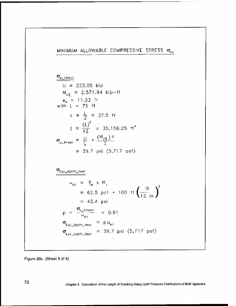
MINIMUM ALLOWABLE COMPRESSIVE STRESS azu
<-'u_Linear
U = 223.05 kip Mut = 2,571.94 kip-ft
eu = 11.53 fi with L = 75 ft
c = 4p- = 37.5 ft
(L)3
I = ±j- = 35,156.25 ft
a = U. + (Mut)c
u_linear i T
= 39.7 psi (5,717 psf)
aEqv. .Uplift. _heel
?w x UH1 = H,
= 62.5 pct
— 43.4 psi
= u_Linear P
UH1
\12 in /
Eqv_Uplift_Heel ^ UH1
a = 39.7 psi (5,717 psf) Eqv_Uplift_Heel r \ r /
Figure 29c. (Sheet 3 of 4)
72 Chapter 5 Calculation of the Length of Cracking Using Uplift Pressure Distributions of Both Agencies

<*zu
<*2U = P\ H1 * S
with f, = 0
zu Eqv_Uplift_Heel
CTZU = 39.7 psi (5,717 psf)
Total Slress at Heel
N. . . ( N e)c (T — total _ v total J
total_Heel I l
= -33.4 psi (4,810 psf)
Crack Test
^totd.Heei < ^zu Therefore a crack will develop.
Figure 29d. (Sheet 4 of 4)
Chapter 5 Calculation of the Length of Cracking Using Uplift Pressure Distributions of Both Agencies 73

Drain Effectiveness E = 0.25, Tailwater Drain location xd = 10 ft from heel, L = 75ft
Yw = 62.5 pcf £h- L/2
I-^J i-?a-/ Tailwater, H2 = 5 ft
Z® UH2 = X,H2
uu, = 312.5 psf (2.17 psi)
Pool, H,
= 6,250 psf (43.4 psi)
H3 = 77.5 ft
"H3 = *WH3
= 4,843.75 psf
(33.64 psi)
Moment about <L
M, = fau
F;. = 223.05 kip ML 2,571 94 k P- -ft
eu 11.53 ft
a) Uplift Profile (Pore water pressures)
230 psf (1.60 psi)
u_linear
Moment about (£
Mu = Fueu
°u_linear = —— I 1 + — )
b) Linear Uplift Profile
= 5,717 psf (39.70 psi)
-t- = 12.5 ft 6
a = 0 Eqv_Uplift_toe
Eqv_Uplift_heel
= PYwH,
c) Triangular Equivalent Uplift Profile
<*r ,, i.« v. i = 5,717 psf Eqv_Uphft_heel , * __ r .v (39.70 psi)
Figure 30. Calculation made for the Reclamation drain factor p with full base contact, E = 0.25, and tailwater at 5 ft (1 ft = 0.305 m, 1 kip = 4.448 kN, 1 kip-ft = 1.356 kN-m, 1 pcf =16.018 kg/m , 1 psf = 47.88 Pa, 1 psi = 6.894 kPa)
74 Chapter 5 Calculation of the Length of Cracking Using Uplift Pressure Distributions of Both Agencies

UH1= ywH1 = 43-4 PS'
Pw, Upllft_heel.
eff«ctive_Heel
= 6.3 psi
O O
'totaL-Heal -
-33.4 psi
Eqv_UplHt_heel u_llnear
Vlin_ear= 39.70 PSi
^zu = CTEqv_Upl!ft_heel
= 39.70 psi
Linear uplift profile
. Equivalent Uplift \ Profile (Figure 30) \ \
Effective stress (w/ uplift)
——— Uplift profiles
Stresses along base (base pressures)
Crack Test
Total stress (w/o uplift)
77.81 psi-
atotal_Heel < CTzu Therefore a crack will develop.
Figure 31. Minimum allowable compressive stress ozu according to Reclamation criteria and assuming full base contact (1 psi = 6.894 kPa)
Chapter 5 Calculation of the Length of Cracking Using Uplift Pressure Distributions of Both Agencies 75

UH1 =
ywH, = 43.4 psi
'effective = 0 psi
L = 75 ft
Length of
crack T = 30.735 ft
— —, Heel Effective Stress at crack lip
226.72
Linear Uplift Profile
/
Uplift Profile
43.4
Crack tip]
o o
Effecfive stress (w/ uplift)
"total -
-226.72 psi Total stress (w/o uplift)
38.29 psi
2.17 psi Toe
-82.59 psi
-120.88 psi
Uplift profiles
Stresses along base
Figure 32. Crack length T = 30.735 ft according to Reclamation criteria (1 ft = 0.305 m, 1 psi = 6.894 kPa)
76 Chapter 5 Calculation of the Length of Cracking Using Uplift Pressure Distributions of Both Agencies

two computed values for crack length T: (a) for a given value for drain effectiveness E, the Corps uplift distribution is less severe than the Reclamation uplift distribution for this problem, and (b) the calculations following the Corps procedure allowed for consideration of drain effectiveness (E = 0.25) in the cracked base analysis (so long as T is less than the distance from the upstream face to the center line of drains) while E is set equal to zero in the Reclamation cracked-base analysis.
A second series of equilibrium calculations made following the Reclamation engineering procedure and using the Reclamation uplift pressure distribution (Figure 13) established that crack initiation occurs when the reservoir reaches 97.62 ft (29.75 m) (Appendix E). Figure 33 summarizes the resulting stress distributions along the base of the dam for a reservoir elevation equal to 97.62 ft (29.75 m). Note that the value for total stress below the heel o totalheelis equal (in magnitude and opposite in sign) to the minimum allowable compressive stress oz„. These calculations are made using the Reclamation Figure 13 uplift pressure distribution with drain effectiveness E equal to 0.25. Crack initiation is at a 1.3-ft- (0.40-m-) lower reservoir elevation using the Figure 13 Reclamation uplift pressure distribution compared with the elevation computed using the Corps Figure 8 uplift pressure distribution.
5.4 Stability Calculations Made Using FERC Engineering Procedure and Uplift Distributions
Stability calculations made of the Figure 20 concrete gravity dam section using the FERC engineering procedures were conducted using the FERC uplift distributions but with a unit weight of water set equal to the FERC standard value of 62.4 pcf (999.5 kg/m3) (Appendix F). The predicted crack length is 7.64 ft (2.33 m), which is slightly less than the 8.23 ft (2.51 m) calculated using a unit weight of water equal to 62.5 pcf (1,001.13 kg/m3) (calculations not shown). This difference in computed crack length is attributed to the fact that the FERC engineering procedure uses a unit weight of water that is slightly less than the value of 62.5 pcf (1,001.13 kg/m3) that is commonly used by the Corps. The uplift distributions assumed by FERC are identical to those assumed by the Corps with the exception of the case where cracking extends beyond the drains and the drains remain effective.
5.5 Conclusions
The calculations summarized in this chapter demonstrate that the Corps and Reclamation uplift distributions differ. For the gravity dam section analyzed in this chapter and given the same value for drain effectiveness E (0.25), the Recla- mation uplift distribution is more severe on the crack extent calculation. Addi- tionally, because the calculated pool elevation at which a crack develops below
Chapter 5 Calculation of the Length of Cracking Using Uplift Pressure Distributions of Both Agencies 77

um= YWH, = 42.37 ps
l_ Eqi/_Upim_heelJ
"effec1ive_Hesl
= 0.00 psi
"totoLHeel
-38.78 psi
Full uplift, -no iailwater, no drains
<j = a Eqv_Upl[ft_heel u_llnear
or= 38.78 psi
0'Eqv_UpliH_heel
= 38.78 psi
Uplift profiles Stresses along base (base pressures)
72.44 psi
Figure 33. Reservoir elevation W, = 97.62 ft resulting in atotal_Hee! equal to ozu using Reclamation criteria (1 ft = 0.305 m, 1 psi = 6.894 kPa)
78 Chapter 5 Calculation of the Length of Cracking Using Uplift Pressure Distributions of Both Agencies

the heel of the dam is slightly lower (by 1.3 ft (0.40 m)) when using the Reclamation uplift distribution, it is reasoned that crack potential is slightly more severe when using the Reclamation uplift pressure distribution. Recall that calculations discussed in Chapter 4 show that any difference in crack potential cannot be attributed to differences in the Corps and Reclamation engineering procedures.
The uplift distributions assumed by FERC are identical to those assumed by the Corps with the exception of the case where cracking extends beyond the drains and the drains remain effective. Because the same uplift assumptions are used, the FERC and Corps analyses will yield identical results when the same value of unit weight of water is assigned to both analyses. However, the calculations summarized in this chapter demonstrate that the Corps and the FERC engineering procedures differ by the unit weight of water assigned to the computations. The unit weight of water of 62.4 pcf (999.5 kg/m3) used in FERC engineering procedures is slightly less than the value of 62.5 pcf (1,001.13 kg/m3) that is commonly used by the Corps. Consequently, the FERC calculations resulted in a 0.59-ft (0.18-m) shorter length of crack than computations made following the Corps procedure. Thus, it is reasoned that crack potential is slightly less severe when using the FERC procedure.
Chapter 5 Calculation of the Length of Cracking Using Uplift Pressure Distributions of Both Agencies 79

6 Summary and Conclusions
This report summarizes the results of an investigation of key aspects of guid- ance published by the Corps, Reclamation, and FERC used to calculate the stability of a concrete gravity dam section. An important issue regarding the engineering procedures as practiced by all three agencies when performing stability calculations is how uplift water pressures are to be computed and applied in the calculations. The objective of this report is to identify similarities, as well as differences, in the calculation of uplift as well as crack initiation and crack propagation in the stability of concrete gravity dams.
6.1 Stability Criteria for the Corps and Reclamation
The stability criteria and the engineering procedures used to calculate the sta- bility of concrete gravity dams according to guidance published by the Corps and Reclamation are summarized in Chapter 2 of this report. The guidance for the design of gravity dams is given in terms of the conventional equilibrium method of analysis.
6.1.1 Similarities
Both Federal agencies share the following basic stability requirements for a gravity dam for all conditions of loading:
a. That it be safe against overturning at any horizontal plane within the structure, at the base, or at a plane below the base.
b. That it be safe against sliding on any horizontal plane within the structure, at the base, or at a plane below the base.
c. That the allowable unit stresses in the concrete or in the foundation material shall not be exceeded.
80 Chapter 6 Summary and Conclusions

The stability of concrete gravity dams is evaluated for more frequent, usual loadings, and less frequent, unusual and extreme loadings. The stability criteria against sliding and overstressing of material regions within either the gravity dam or its foundation are expressed in terms of either minimum values for the factors of safety or maximum allowable stresses. Although not exactly the same, these limiting parameter values are generally consistent for the Corps and Reclamation.
Both agencies describe their stability criteria for concrete gravity dam sections using conventional equilibrium analyses and limit state theory. Both agencies evaluate the level of stability of a concrete gravity dam using computations for cracking potential and sliding stability. The Corps uses the location of the force resultant at the base of the dam, and Reclamation uses stresses computed at the upstream face of the concrete gravity dam to judge the safety of the gravity dam. Neither agency specifically expresses stability against overturning of the concrete gravity dam section in terms of a factor of safety against overturning about its downstream face.
Both agencies compute the same crack initiation and the same crack propaga- tion length when identical uplift profiles are used. The procedural calculations are different because the Corps calculates the location of the force resultants while Reclamation calculates stresses. The results are identical when identical forces are used. A key reason for calculating the same crack propagation length is the Corps' assumption of a linear effective base pressure distribution and Reclamation's assumption of a linear total base pressure distribution.
6.1.2 Differences
The engineering procedures used by the Corps and Reclamation to compute stability differ in two key aspects. First, the Corps expresses stability by the resultant location along the base of the idealized dam section, while Reclamation expresses stability in terms of cracking potential (evaluated at any critical point(s), e.g., below the heel of the dam). Second, the agencies' guidance for incorporating the effects of uplift pressures in the stability analysis are different. The Corps includes uplift pressures in the free body section of the gravity dam when computing the vertical component of the resultant force and its point of action (Figure 1) and effective base pressure distribution (Figure 2). Reclamation incorporates the effects of uplift pressures in the last stage of the evaluation of the cracking potential below the heel of the gravity dam section using the minimum allowable compressive stress criteria ozu. However, the results are identical when all the forces are identical.
Chapter 6 Summary and Conclusions 81

6.1.3 Calculation of the length of cracking along the base of a 100-ft- (30.5-m-) high gravity dam section using the conventional equilibrium analyses and using the Corps uplift pressure distribution
Chapter 4 in this report summarizes the calculation of the stability of an example gravity dam section using the Corps and Reclamation engineering procedures. The uplift water pressure distribution applied in both sets of calculations is stipulated as that developed in accordance with guidance published in EM 1110-2-2200 used to design gravity dams. These calculations demonstrate that given the same uplift distribution, the Corps and Reclamation engineering methodologies to calculate crack extent are the same. Additionally, because the calculated pool elevation at which a crack develops below the heel of the dam is the same for the two engineering procedures when the same uplift distribution is used in the calculations, it is reasoned that crack potential is consistent for the two engineering procedures.
6.2 Uplift Pressure Criteria for the Corps and Reclamation
The calculation of uplift pressures according to guidance published by the Corps and Reclamation is summarized in Chapter 3 of this report. Only that portion of guidance relating to an imaginary section made through the base of the dam is described.
Uplift pressure resulting from headwater and tailwater exists through cross sections within the dam, at the interface between the dam and the foundation, and within the foundation below the base. This pressure is present within the cracks, pores, joints, and seams in the concrete and foundation material. Uplift pressure is an active force that must be included in the stability and stress analysis to ensure structural adequacy. These pressures vary with time and are related to boundary conditions and the permeability of the material. Uplift pressures are assumed by both Federal agencies to be unchanged by earthquake loads.
6.2.1 Uplift criteria for the Corps and Reclamation
Both Federal agencies include uplift in their stability calculations. The following subsections summarize the similarities as well as differences among the uplift criteria.
One of the key differences between the two agencies' guidance for calculating the stability of a gravity dam section is the nonsite-specific equations used to calculate uplift pressures. Specific issues include uplift pressure distributions with or without cracking and the length of crack propagation as it relates to the distribution of uplift pressure.
82 Chapter 6 Summary and Conclusions

6.2.1.1 No foundation drains. When foundation drains are not present or are inoperable, the distribution of uplift pressures is the same for all agencies, corresponding to the full reservoir pressure head Hx below the heel of the dam, full tailwater pressure head H2 below the toe, and with a linear variation in pressure head along the base.
6.2.1.2 Foundation drains and full base area contact. The uplift pressure distributions of the two agencies are slightly different in the case of dams with foundation drains and full contact along the base. Three key factors contribute to these differences in the calculation of uplift pressures:
a. The Corps and Reclamation differ on their recommendation for the value to be assigned to drain effectiveness E. The Corps limits the value for E to 0.5 in the case of nonsite-specific uplift data while Reclamation assigns a value to E of 0.66 for new designs.
b. In the case of the elevation of the floor of the drainage gallery above tailwater (#4 > H2), the pressure head H3 at the drain is given in Corps guidance (Figure 8) as
H3 =K (Hi _ H2) iL-Il +H2-H4 + HA (7)
while H3 is given in Reclamation guidance (Figure 13) as
H3 =K{H,- H4) + H4 (8)
with K = 1 - E. The uplift pressure at the base of the dam at the line of drains is equal to yw times H3 Given the same value for drain effectiveness E, the criteria giving the larger magnitude of computed uplift pressures will depend on the location of the drain X along the base of length L, the height of the tailwater H2, and height of drain H4.
c. In the case of the elevation of the floor of the drainage gallery below tail- water (H4 < H2), the pressure head H3 at the drain is given in Corps guid- ance (Figure 8) as
H3 = K (Hi - H2) iLjJD. + H7 (9)
while H3 is given in Reclamation guidance (Figure 12) as
H3 =K(H1 - H2) + H2 (10)
Because the Corps criterion multiplies the difference between headwater and tailwater by the term (L - X)/L, H3 will always be higher using
Chapter 6 Summary and Conclusions 83

Reclamation criteria than Corps criteria given the same value for drain effectiveness E.
6.2.1.3 Foundation drains, partial base area contact, and crack ends prior to line of drains. When the crack does not extend to the line of drains, the Corps engineering design procedure allows for consideration of drain effectiveness. This contrasts with the Reclamation procedure, which assumes the drain ineffective when cracking initiates unless measurements are contrary.
6.2.1.4 Foundation drains and partial base area contact with crack extending beyond the line of drains. Uplift pressure distributions computed using the Corps and Reclamation procedures are the same when the crack extends beyond the line of drains. The drains are considered to be ineffective (E = 0) in this case. This distribution is full reservoir head (H^) in the entire crack, then linear varying ftomH1 at the crack tip to tailwater (H2) at the toe.
6.2.2 Crack initiation/propagation for the Corps and Reclamation
Both Federal agencies define the engineering procedures to be followed when the calculations show a potential for cracking along the base of the dam in the stability calculations. The following subsections summarize the similarities as well as differences between the two agencies.
6.2.2.1 Crack initiation. Both agencies recognize in their guidance that the area with the greatest potential for cracking to initiate is below the heel of the dam. However, the Corps and Reclamation differ on the calculations made to determine when cracking initiates.
The Corps establishes the potential for cracking along the base by comparing the minimum value of effective normal stress P'min, against the tensile capacity for the region in question. Cracking initiates below the heel of the dam if P'min is tensile and exceeds the tensile capacity of the material. The tensile capacity along the base of a gravity dam section is often set equal to zero in these calculations. To calculate the distribution of effective stresses along the base, the normal component of the resultant force R is converted to a linear distribution of effective base pressure using the equations given in Figure 2. Recall that uplift pressures are included in the calculation of R, as depicted in Figure 1.
Reclamation establishes the potential for cracking along the base by comparing the induced total stress oz at the heel using the equations given in Figure 4 with oz„. Recall that azu is calculated by:
= pwh - (4)
84 Chapter 6 Summary and Conclusions

Recall that/, is the tensile strength of the material and 5 is the safety factor. The term pwh represents the transformed uplift pressure below the heel of the dam, as shown in Figures 17 through 19. Recall that the resultant uplift force and its point of application are the same for both the actual and transformed (triangular) uplift pressure distributions in these calculations only for the case of no tailwater and no drains (Figure 17). Cracking initiates below the heel of the dam when the compressive stress oz does not achieve the minimum compressive stress a2U
value.
Reclamation crack initiation criteria represent the "demand" below the heel of the dam by a transformed uplift pressure. Figures 18 and 19 show that this transformed uplift pressure below the heel can be less than the actual uplift pressure when drains are present. Comparisons of crack initiation calculations made between the Corps guidance and Reclamation guidance indicate the following:
a. The two procedures produce the same results when all the applied forces on the dam section are identical.
b. The methodologies are different. The Corps calculates effective base pressures and compares the location of the resultant (effective) force. Reclamation calculates the total stress at the heel without uplift and compares this stress to an equivalent uplift stress am at the heel.
c. The assumed uplift profiles below the dams are identical without drainage.
d. The assumed uplift profiles below dams with drains are different for two reasons: (1) the assumed drain effectiveness is different, and (2) the equations calculating the uplift pressures at the drains are different.
6.2.2.2 Crack propagation. The length of cracking along the base is com- puted according to both Corps and Reclamation criteria using iterative calcula- tions to determine the length of crack resulting in an effective stress at the crack tip of zero (or equal to the allowable tensile strength for the material). The methods used by the Corps and Reclamation compute the same crack length when the uplift profiles are the same. However, differences may exist in the computed length of crack because of differences in the uplift pressure distribution being used in these calculations. For example, Reclamation guidance does not allow for drain effectiveness once a crack has formed while Corps guidance allows for consideration of drain effectiveness so long as the crack does not extend to or beyond the drain.
Chapter 6 Summary and Conclusions 85

6.2.3 Calculation of the length of cracking along the base of a 100-ft- (30.5-m-) high gravity dam section using the conventional equilibrium analyses and using uplift pressure distributions according to guidance employed by the Corps and Reclamation
The calculations summarized in Chapter 5 of this report demonstrate that the Corps and Reclamation uplift distributions differ. For the gravity dam section analyzed and given the same value for drain effectiveness E (0.25), the Reclama- tion uplift distribution is more severe on the crack extent calculation. Addition- ally, because the calculated pool elevation at which a crack develops below the heel of the dam is slightly lower (by 1.3 ft (0.40 m) when using the Reclamation uplift distribution, it is reasoned that crack potential is slightly more severe when using the Reclamation uplift pressure distribution. Any differences in crack potential cannot be attributed to differences in Corps and Reclamation methodology as demonstrated by the calculations made in Chapter 4 but are due to differences in uplift distributions as demonstrated by calculations made in Chapter 5.
6.3 Stability Criteria for FERC and the Corps
FERC stability criteria closely resemble the criteria used by the Corps. The two criteria have the following differences:
a. FERC does not require different factors of safety for the different static load cases. Rather, a factor of safety of 1.5 is required for the worst static load case.
b. The FERC sliding analysis assumes no cohesion.
c. FERC limits the shear strength of concrete in conformance with ACI 318 (ACI1995).
6.4 Uplift Pressure Criteria for FERC and the Corps
FERC uplift pressure criteria closely resemble the criteria used by the Corps. The two criteria have the following differences:
a. FERC requires that the drain effectiveness assumptions be justified by actual piezometric readings specific to the load case being analyzed.
°" Chapter 6 Summary and Conclusions

b. FERC assumes a unit weight of water of 62.4 pcf (999.5 kg/m3), which is slightly less than the value of 62.5 pcf (1,001.13 kg/m3) that is commonly used by the Corps.
c. FERC allows for drain effectiveness when cracking extends downstream of the drain line based on piezometric measurements.
Chapter 6 Summary and Conclusions 87

References
American Concrete Institute. (1995). "Building code requirements for structural concrete and commentary," ACI 318-95/318R-95, Farmington Hills, MI.
Bureau of Reclamation. (1987). "Design of small dams," 3rd ed., Washington, DC.
Federal Energy Regulatory Commission (FERC). (1999). Draft of FERC guidance on the stability of concrete gravity dams (in preparation), Washington, DC.
Headquarters, U.S. Army Corps of Engineers. (1995 (30 June)). "Gravity dam design," Engineer Manual 1110-2-2200, Washington, DC.
Headquarters, U.S. Army Corps of Engineers. (1999). Draft of "Stability analysis of concrete structures," Engineer Manual 1110-2-2100 (in preparation), Washington, DC.
MathSoft, Inc. "MathCad," 101 Main Street, Cambridge, MA.
Raphael, J. M. (1984). "Tensile strength of concrete," ACI (American Concrete Institute) Journal, March-April issue, 158-165.
88 References

Appendix A Corps Definition of Drain Effectiveness
A.1 Introduction
This appendix describes the Corps definition of drain effectiveness E, which is equal to a decimal fraction that ranges from 0 to 1.0. E is defined in terms of magnitude of pore-water or uplift pressure acting at the base of a dam section at the line of drains, relative to the two limiting values possible. The first limiting value corresponds to the case of the drains being fully effective and able to dis- charge the foundation seepage that enters the drains without head loss as the water flows upward to the floor of the drainage gallery. The drain is fully effective in this case and the value of E is equal to 1.0. The second limiting case corresponds to the other extreme of an ineffective drain, for which E is equal to zero. A fully clogged drain would be assigned an E value of zero. The two sets of equations listed in Figures A.1 and A.2 and used to define the uplift pressures for a given drain effectiveness E value are distinguished by the elevation of tailwater relative to the elevation of the floor of the drainage gallery. All equations listed allow for consideration of a crack extending from the upstream face of the dam to any point located in front of the line of drains. The symbols used in the equations are defined as follows:
H1 = reservoir pressure head above the dam base at the upstream face
H2 = tailwater pressure head above the dam base at the downstream face
H3' = calculated pressure head above the dam base at the drain location with E = 0 (and K=1.0)
H3" = calculated pressure head above the dam base at the drain location with £ = 1.0 (and K=0)
Appendix A Corps Definition of Drain Effectiveness A1

A2
H3 = calculated pressure head above the dam base at the drain location with specified E
H4 = height of the drainage gallery floor above the dam base
L = length of dam base from upstream to downstream
X = distance from upstream face to center line of drains
T = crack length
E = drain effectiveness, where 0 < E < 1.0
K=(l-E)
yw = unit weight of water
A.2 Drain Effectiveness in the Case of the Floor of the Drainage Gallery Above Tail water
Figure A.1 shows the set of three uplift distributions and corresponding equa- tions for uplift pressures at the line of drains for a dam with the elevation at the floor of the drainage gallery above the tailwater elevation. T designates the length of crack as measured from the front face of the dam. Figure A. lb shows the uplift distribution for the case of zero drain effectiveness (E = 0). This distri- bution is the worst case scenario for the dam and therefore corresponds to an E value equal to zero. Note that when the base of the dam is in full contact with the rock foundation, the uplift pressure at the line of drains is computed by setting the crack length T equal to zero in all equations in Figures A.1 and A.2. The Figure Ale uplift distribution represents the best case scenario for the dam and therefore corresponds to an E value equal to 1.0. In this case the uplift pres- sure at the line of drains is equal to the unit weight of water yw times the difference between elevations of the floor of the gallery and the base of the dam H4. Figure A. Id shows the intermediate case of partial drain effectiveness. Recall that Corps guidance restricts the value forii to between 0.25 and 0.5 for dams without site-specific uplift pressure measurements.
A.3 Drain Effectiveness in the Case of the Floor of the Drainage Gallery Below Tailwater
Figure A.2 shows the set of three uplift distributions and corresponding equa- tions for uplift pressures at the line of drains for a dam with the elevation at the floor of the drainage gallery below the tailwater elevation. Figure A.2b shows the uplift distribution for the case of zero drain effectiveness (E = 0). This distribution is the worst case scenario for the dam and therefore corresponds to
Appendix A Corps Definition of Drain Effectiveness

an E value equal to zero. The Figure A.2c uplift distribution represents the best case scenario for the dam and therefore corresponds to an E value equal to 1.0. The uplift pressure at the line of drains is equal to the unit weight of water yw
times the difference between elevations of the tailwater and the base of the dam H2. Because most dams use gravity flow to tailwater to drain the gallery and with the tailwater above the floor elevation of the drainage gallery, the elevation of tailwater dictates the head boundary condition at the top of the drain. Thus, the uplift pressure at the line of drains is larger in this case (Figure A.2c) than that shown in Figure A.lc. Figure A.2d shows the intermediate case of partial drain effectiveness. Again, Corps guidance restricts the value foris to between 0.25 and 0.5 for dams without site-specific uplift pressure measurements.
Appendix A Corps Definition of Drain Effectiveness A3

Drainage Gallery
H4>H2
Gravity flow to downstream
Tailwater V/
(£_of Drains
w h e re: T = crack length
(a) Gravity dam cross-section for case of H.>H 4 ■ '2
y H w' '1
y Ho
H, = (H,- H2)
where: E = effectiveness of drain expressed as a decimal fraction (0 < E < 1.0)
Note: If H/ < H, then E = 0 3 4
(b) Uplift distribution cracked base with no drain effectiveness
Figure A.1. Explanation of the EM 1110-2-2200 Figure 3-4 equation in the case of the elevation of the floor of the drainage gallery above tailwater (Continued)
A4 Appendix A Corps Definition of Drain Effectiveness

If H,7 > H4 then (Lof Drains
Yw h^
YwH w' '2 Full Drain
Effectiveness E = 1.0
H,
(c) Uplift distribution cracked base with full drain effectiveness
YWH1
Partial Drain Effectiveness 0 < E < 1.0
H3 = K (H1-H2)^+ H2- H4 + H,
/ Note: H3 = K(H3- H4) + H4
and K = 1-E
(d) Uplift distribution cracked base with partial drain effectiveness
Figure A. 1. (Concluded)
Appendix A Corps Definition of Drain Effectiveness A5

Headwater
Drainage Gallery
H4<H2
Gravity flow to downstream
Tailwater V
H.
where: T = crack length
(£_of Drains
(a) Gravity dam cross-section for case of H4< H2
Y...H,
No Drain Effectiveness
E = 0
H5 = (H,- H2) L-X
L-T + H.
where: E = effectiveness of drain expressed as a decimal fraction (0 < E < 1.0)
Note: If H37< H2 then E = 0
(b) Uplift distribution cracked base with no drain effectiveness
Figure A.2. Explanation of the EM 1110-2-2200 Figure 3-4 equation in the case of the elevation of the floor of the drainage gallery below tailwater (Continued)
A6 Appendix A Corps Definition of Drain Effectiveness
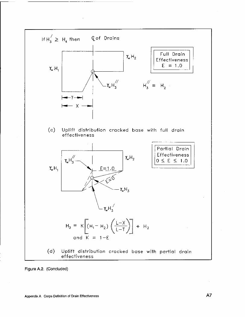
If H, > HA then <L°f Drains 3 4
yw H1
Y„H w' '2 Full Drain
Effectiveness E = 1.0
// -YWH3
X
(c) Uplift distribution cracked base with full drain effectiveness
YwH,
Partial Drain Effectiveness 0 < E < 1.0
H3 = K (H.-H,)!^- + H-
and K = 1-E
(d) Uplift distribution cracked base with partial drain effectiveness
Figure A.2. (Concluded)
Appendix A Corps Definition of Drain Effectiveness A7

Appendix B Reclamation Definition of Drain Effectiveness and of Crack Initiation
B.1 Introduction
This appendix contains equations for uplift at the drains and cracking in the concrete as described in Reclamation criteria (Bureau of Reclamation 1987). *
B.2 Equations for Pressure Head at the Drains
The equations for uplift at the drains are listed for various lengths of crack and if the tailwater is above or below the drainage gallery. The equations use the following nomenclature:
Hx = reservoir pressure head above the dam base at the upstream face
H2 = tailwater pressure head above dam base at the downstream face
H3 = calculated pressure head above the dam base at the drain location
H4 = height of the drainage gallery above the dam base
L = length of dam base from upstream to downstream
B = uncracked dam base, B =L -T
X = distance from upstream face to drain location that intersects the horizontal plane (i.e., if the drains are angles)
1 References cited in this Appendix are included in the References at the end of the main text.
Appendix B Reclamation Definition of Drain Effectiveness and of Crack Initiation B1

T = crack length from upstream face
E = drain effectiveness, where 0.0 = no reduction, 1.0 = full reduction
K = drain efficiency = (1 - E), where 1.0 = no reduction, 0.0 = full reduction
B.2.1 For the condition when the tailwater (H£ is higher than the drainage gallery (HJ
When the tailwater elevation is higher than the drainage gallery elevation, the calculations for pressure head at the drains (H3) are made assuming the drainage gallery elevation is at the same elevation as the tailwater.
B.2.1.1 No crack exists. Equation B.l is used by Reclamation for H3 when the H2 is at a higher elevation than #4 and no crack exists in the concrete (Fig- ure B.l). The computed uplift pressure at the drains (H3) will be different using Reclamation criteria from that computed using the Corps criteria given the same lvalue based on the position of the drains.
H3 = (Hx - HJK + H2 , H3max (H2 > HA, T = 0) (B.l)
The maximum pressure at the drains is a condition without drains. Equation B.l can produce higher pressure values than the maximum condition without drains, so the maximum value of H3 is given in Equation B.la. Notice that the equation fori/3max equals the equation foiH3 by the Corps when K equals 1.0:
The range of possible permissible values for K and E are:
0.33 < K < 1.0 (B.lb)
0.66 > E > 0.0 (B.lc)
B.2.1.2 Crack length has not reached drains. Reclamation criteria assume full reservoir head in the entire length of the crack and the drains become ineffective under steady state conditions once a crack forms unless there are measurements to the contrary. (Note: Current practice includes a drain efficiency factor (K, K = 1 - E) in the calculation for Equation B.2.) Equation B.2 is used for H3 when H2 is at a higher elevation thanif4 and the crack length T has not reached the drains X. The uplift distribution is bilinear from full reservoir head at the upstream face to full reservoir head at the crack tip to tailwater elevation at the downstream toe (Figure B.2).
"^ Appendix B Reclamation Definition of Drain Effectiveness and of Crack Initiation

Tailwater Elevation (H2) > Gallery Elevation (H4)
No Crack (7=0)
IV
HI
_SZ_
i. X. ■c ">
c
[Note: 0.33 ^ K ^ 1.0]
(Equation B. 1b)
SI j H2
ywH1
X
USBR
ywH2
H3=(H1-H2)K + H2 Established from historic data
(Equation B. 1)
._ X _. • »
7wH1
7«H2
7„"3 H3Max-
(L-X)(H1-H2) + H2
(Equation B. 1a)
Figure B.1. Reclamation uplift profiles with drainage gallery below tailwater and full contact along base
Appendix B Reclamation Definition of Drain Effectiveness and of Crack Initiation B3

H3 = £LL%L2L-2. + H2 (H2>H4,0<T<X) (B.2)
B.2.1.3 Crack length at drains. Equation B.3 is used for H3 when H2 is at a higher elevation than H4 and the crack length T has reached the drains X. The uplift distribution is bilinear from full reservoir head at the upstream face to full reservoir head at the crack tip to tailwater elevation at the downstream toe (Figure B.2).
H3 = Hx (H2 >H4,T=X) (B.3)
2 B.2.1.4 Crack length beyond drains. Equation B.4 is used for H3 when H is at a higher elevation thani/4 and the crack length Tis beyond the drains X. The uplift distribution is bilinear from full reservoir head at the upstream face to full reservoir head at the crack tip to tailwater elevation at the downstream toe (Figure B.2).
H3 = Hx (H2 >HA,T>X) (B.4)
B.2.2 For the condition when the gallery elevation H4 is higher than the tailwater elevation H2
When the gallery elevation is at a higher elevation than the tailwater elevation, the calculations for pressure head at the drains (H3) are made assuming the tailwater is at the same elevation as the drainage gallery.
B.2.2.1 No crack exists. Equation B.5 is used by Reclamation for H3 when the H4 is at a higher elevation than H2 and no crack exists in the concrete. Equa- tion B.5 is similar to Equation 7 (main text) used by the Corps, except Reclama- tion multiplies the drain efficiency (K, K = 1 - E) by the difference between the reservoir and tailwater levels (H1 - H4) and the Corps multiplies the drain effec- tiveness by the head at the drain without drains as in Figure 8 (main text). As a result, the computed uplift pressure at the drains H3 using Reclamation criteria will be different from the Corps criteria given the same lvalue based on the position of the drains, the tailwater elevation, and the height of the gallery (Figure B.3).
H3 = {Hx -H4)K + H4± i/3max (H4>H2, T - 0) (B.5)
The maximum value of H3 is the condition without drains. The height of the gallery does not affect this equation, because the maximum pressure head at this location is without drains.
H^-^Y^^-H^H, (B.5a)
°4 Appendix B Reclamation Definition of Drain Effectiveness and of Crack Initiation
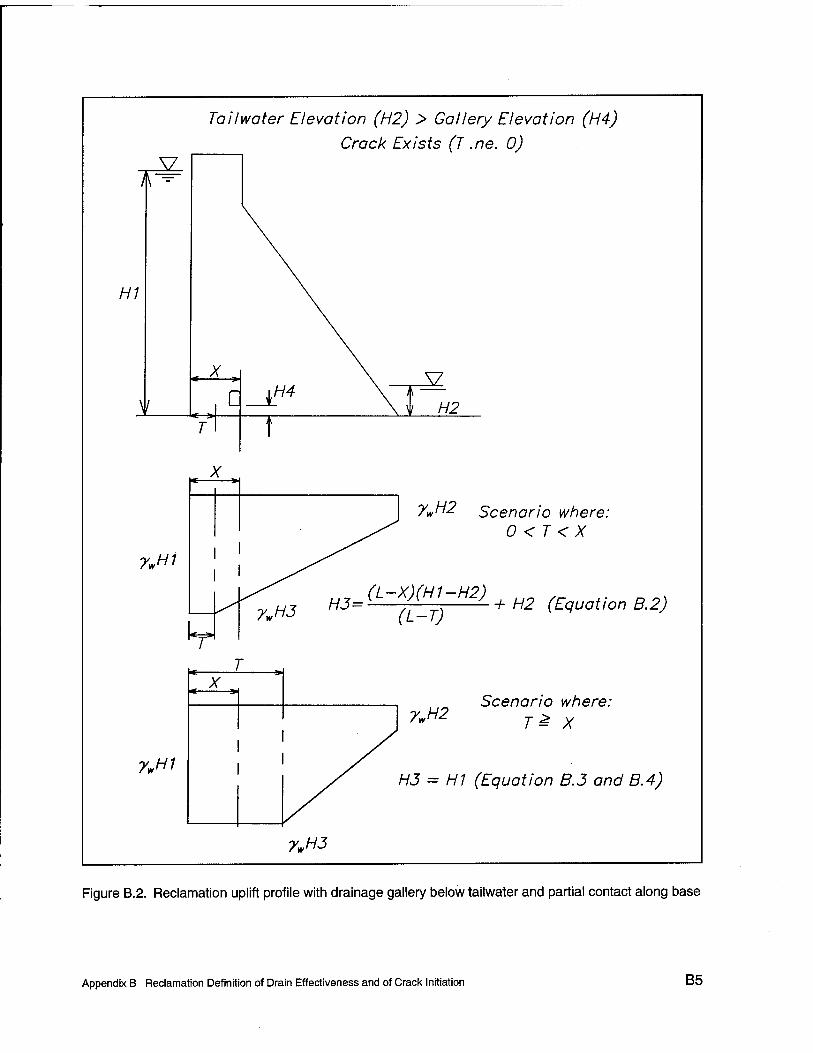
Tauwetter Elevation (H2) > Gallery Elevation (Hi)
Crack Exists (T .ne. 0) V
1 \ -
H1
\ /
,._X.j
\h
\ Y7
c 14 \ i i H2
T t
X y
7V/H2 Scenario where: ^^ o < r<x
7wH1 I I
■%H3 H3- «--M™-»2) + H2 (Equation B.2)
kH 7
x a Scenario where-
7wH2 T ^ X I /
ywH1 I I
/ H3 = HI (Equation B.J and B.4)
7wH3
Figure B.2. Reclamation uplift profile with drainage gallery below tailwater and partial contact along base
Appendix B Reclamation Definition of Drain Effectiveness and of Crack Initiation B5

I*
Gallery Elevation (H4) > Tailwater Elevation (H2)
No Crack (T=0)
HI
V
X Q
«———>
7wH1
X
7wH3
7wH1
^U
7wH3
SI H2
7wH2
HJ=(H1-H4)K + H4
(Equation B.5)
7wH2
_ (L-X)(H1-H2) ''Max ~~ j_
(Equation B.5a)
+ H2
Figure B.3. Reclamation uplift profiles with drainage gallery above tailwater and full contact along base
B6 Appendix B Reclamation Definition of Drain Effectiveness and of Crack Initiation

B.2.2.2 Crack length has not reached drains. Reclamation assumes full reservoir head in the entire length of the crack and the drains become ineffective once a crack forms. Equation B.6 is used for H3 when H4 is at a higher elevation than H2 and the crack length Thas not reached the drains X. The height of the gallery does not affect this equation, because the maximum pressure head at this location is without drains. The uplift distribution is bilinear from full reservoir head at the upstream face to full reservoir head at the crack tip to tailwater eleva- tion at the downstream toe (Figure B.4).
(H,-H~)(L-X) m„ H3 = ^J "I L + H2 (HA>H2,0<T<X) (B.6)
B.2.2.3 Crack length at drains. Equation B.7 is used for H3 when H4 is at a higher elevation than H2 and the crack length T has reached the drains X. The uplift distribution is bilinear from full reservoir head at the upstream face to full reservoir head at the crack tip to tailwater elevation at the downstream toe (Fig- ure B.4). The bilinear pressure distribution is identical to the scenario in section B.2.1.2.
H3 = Hx (HA >H2,T=X) (B.7)
B.2.2.4 Crack length beyond drains. Equation B.8 is used for H3 when H2
is at a higher elevation than H4 and the crack length Jis beyond the drains X. The uplift distribution is bilinear from full reservoir head at the upstream face to full reservoir head at the crack tip to tailwater elevation at the downstream toe (Figure B.4). The bilinear pressure distribution is identical to the scenario in section B.2.1.2.
H3 = Hx (H4 >H2,T>X) (B.8)
B.3 Stress-Based Crack Criteria
Reclamation uses a stress-based criterion to determine when a crack might initiate on the upstream face of a concrete dam from induced loads. The flexure formula is used when calculating the vertical normal stress at locations along the base of the dam. Equivalent flexure formula stresses are related to total stress, effective stress, and pore-water pressure.
B.3.1 Flexure formula
The flexure formula (Equation B.9) is used to calculate the vertical normal stresses at any point on a horizontal plane through the dam. This formula assumes plane sections remain plane and stress distribution is linear from the upstream face to the downstream face. The calculated vertical normal stress at any point along a horizontal plane is the stress induced by the axial load plus or
Appendix B Reclamation Definition of Drain Effectiveness and of Crack Initiation B7

Gallery Elevation (H4) > Tailwater Elevation (H2)
Crack Exists (T .ne. 0)
l\ —
HI
I
5Z-
Q ^U
y\ ., X . I* >
7.H1
7wH1
SI H2
?w Scenario where: 0 < T < X
HJ= (L-XXH1-H2) + H2
(L-T)
(Equation B.6)
Scenario where: 7WH2 Tk x
H3 = HI (Equation B.7 and B.8)
7WH3
Figure B.4. Reclamation uplift profiles with drainage gallery above tailwater and partial contact along base
B8 Appendix B Reclamation Definition of Drain Effectiveness and of Crack Initiation
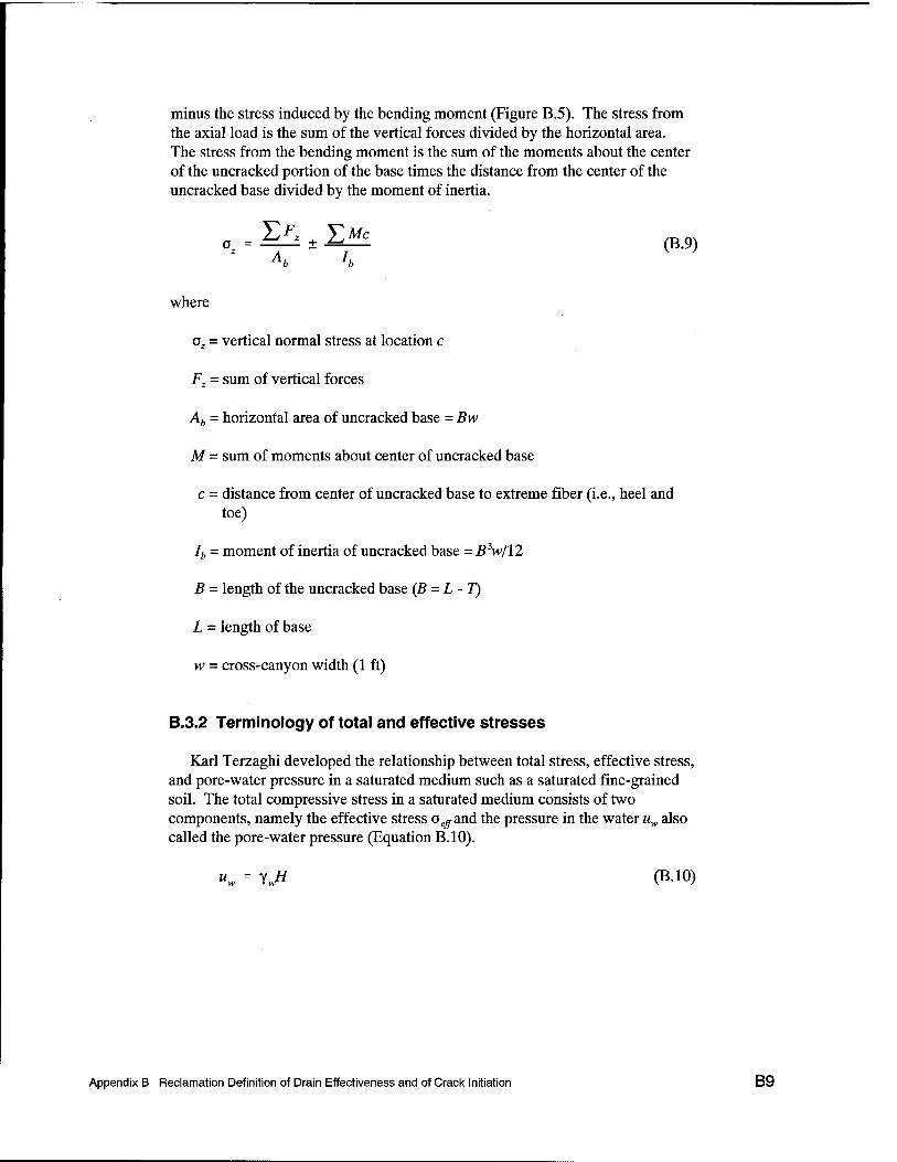
minus the stress induced by the bending moment (Figure B.5). The stress from the axial load is the sum of the vertical forces divided by the horizontal area. The stress from the bending moment is the sum of the moments about the center of the uncracked portion of the base times the distance from the center of the uncracked base divided by the moment of inertia.
5X + 5>£ (B.9)
where
o2 = vertical normal stress at location c
FT = sum of vertical forces
Ab = horizontal area of uncracked base = Bw
M - sum of moments about center of uncracked base
c = distance from center of uncracked base to extreme fiber (i.e., heel and toe)
Ib - moment of inertia of uncracked base = B3w/12
B = length of the uncracked base (B =L -T)
L = length of base
w = cross-canyon width (1 ft)
B.3.2 Terminology of total and effective stresses
Karl Terzaghi developed the relationship between total stress, effective stress, and pore-water pressure in a saturated medium such as a saturated fine-grained soil. The total compressive stress in a saturated medium consists of two components, namely the effective stress aeffand the pressure in the water uw also called the pore-water pressure (Equation B.10).
"„ = Vj* (B.10)
Appendix B Reclamation Definition of Drain Effectiveness and of Crack Initiation B9

HI
5L.
MH1=Hi * yw
^EqvUpliftHee^
=<?zu W/ ft = 0
ßH3=H3 * yw
Crack tip
^EqvEffHeel
aEqvEffCrkTip
^TotalHeel ^TotolCrkTip
X
u
SZ
\t__H2_
Full uplift
Equivalen
'EQ B11. a)
Uplift Stress (EQ B. 1.1c)
^EqvUpliftToe
-MH2 = H2 * 7*
■ Zero stress
sssure (EQ B. 10)
five Stress B. 11a) ' aEqv£ffToe
'TotalToe
Total stress (EQ B. 11b) (w/o uplift)
Figure B.5. Bureau of Reclamation uplift and stress profiles
B10 Appendix B Reclamation Definition of Drain Effectiveness and of Crack Initiation

where
uw = pore-water pressure = y„H (Note: um = pore-water pressure at upstream face, um = pore-water pressure at downstream face, and um = pore-water pressure at drains)
YH, = density of water
H = depth of water
The effective stress is the difference between the total stress and the pore-water pressure (Equation B.ll). The stress conditions for failure depend solely on the magnitude of the effective stress.
°eff = °Total - Uw (BA1)
where
aeff = effective stress
°Totai = total stress (without uplift)
In relationship to a concrete gravity dam, the total stress along the base is calcu- lated using the weight of the dam and the external loads except uplift such as reservoir, tailwater, silt, and ice. The pore-water pressure is calculated using the uplift profile under the dam.
B.3.3 Terminology for total, equivalent effective, and equivalent uplift stresses
Reclamation calculates the stress due to the equivalent distribution of uplift pressure (rather than the actual or nonsite-specific pore pressure), referred to as the equivalent uplift stress, using the flexure formula when calculating the effec- tive stress (Figure B.5).
a. Equivalent effective stress.
(B.lla) °EqvEff °Total °EqvUpUft
b. Total stress.
n - ^Fr °Total A Ab
+ ^MT*c
h (B.llb)
h
c. Equivalent uplift stress.
Appendix B Reclamation Definition of Drain Effectiveness and of Crack Initiation B11

o . =^£E+ ^MU
*C (B.11C)
"EqvUplift A j Ab lb
where
°EqvEff= equivalent effective stress, which is the total stress minus equivalent uplift stress
oEqvUplift = equivalent uplift stress, which is a vertical stress calculated for estimating the effect of uplift only
FT = sum of vertical forces except from uplift
MT = sum of moments from forces except uplift
Fv = sum of vertical uplift forces only
MD = sum of moments from uplift forces only
c = moment arm to desired stress location
The following nomenclature is used for equivalent uplift stress along base of dam:
oEqvUpliflFull = special case with no drains and no tailwater
oEqvUpiiftHeei = stress at the upstream face
OEqvUpiiftToe = stress at downstream face
The following nomenclature is used for total stress along base of dam:
°Totameei = stress at upstream face
OjcalCrkTip = ^^S at CTack tiP
aTotaiToe = stress at downstream face
B.4 Crack Initiation (GZJ
Reclamation uses the equivalent uplift stress at the heel oEqvUpi^nedin an
expression for the minimum allowable compressive stress (Equation B.12) at the heel of a dam om to determine the potential of a crack forming in the concrete.
a =py wH1-^ (B.12) zu -* ' w 1
° ' 2 Appendix B Reclamation Definition of Drain Effectiveness and of Crack Initiation

where
om = minimum allowable compressive stress at the heel
p = drain factor
= 1.0 for the scenario of no drains and no tailwater
= 0.4 for the scenario of no tailwater, drain effectiveness E = 0.66, drains positioned at 5 percent H1 from upstream face, drains spaced at 10 ft (3.05 m) on centers cross-canyon, and drain diameter at least 3 in. (76.2 mm)
= must be calculated for any other scenario
y„ = density of water
Hx = depth of reservoir above base
/, = tensile strength of concrete
s = safety factor (3 = usual, 2 = unusual, 1 = extreme loading)
The termpYÄ equals the oEqvUpliftHeel (Equation B.llc), and/,/s accounts for the tensile strength of concrete.
The ozu expression is a function of a drain factor, density of water, height of the water, tensile strength of concrete, and a factor of safety. The azu value is then compared to the total vertical stress oTolaIHeel at the heel. Recall that total stress is calculated without uplift. Cracking initiates when ozu exceeds the total stress.
The expression for ozu can be easily misunderstood, so further explanations will be provided here.
The first misunderstanding can occur because the expression is not a value for the pore-water pressure at the upstream face as implied by the YK#I term, but the expression is the equivalent uplift vertical normal stress at the upstream face induced by uplift pressure along the horizontal plane in question in the dam calculated using the flexure formula. This can be seen in Figure B.5, because the equivalent uplift stress is different from the uplift pore-water pressure diagram.
The second misunderstanding can occur from the definition for ozu being the minimum allowable compressive stress, o^ actually equals the tensile stress at the heel induced from uplift forces calculated using the flexure formula subtracted from the allowable tensile stress, o^ is the equivalent uplift stress when the tensile strength of concrete/, is zero strength. The minimum allowable compressive stress refers to the minimum allowable total stress (without uplift). If the total stress is a compressive stress larger than ozli> then there is
Appendix B Reclamation Definition of Drain Effectiveness and of Crack Initiation B13

compression at this location. Therefore, the Reclamation criterion for crack initiation is expressed in Equation B.13 and is similar to Equation B.lla:
JTotalHeel ozu = 0.0 = aEqvEffHeel (B.13)
The third misunderstanding can occur from the drain factory. A drain factor of 0.4 is valid only if the drains are at 5 percent of H1 from the upstream face, there is no tailwater, the drains are spaced at 10 ft (3.05 m) on centers across the canyon, and the drain effectiveness E is 66 percent. A drain factor of 1.0 is valid only if there are no drains or tailwater, and there is linear uplift distribution from full reservoir head at the heel to zero at the toe. The drain factor must be recal- culated for other conditions (Figures B.6 through B.8 show calculation of p for various scenarios of uplift profiles). The value of p is the ratio of the equivalent uplift vertical stress at the heel from the given uplift profile divided by the equivalent uplift vertical stress at the heel from a full uplift profile with no drains and no tailwater (Y„#I) (Equation B.14). To obtain a new value of p, calculate the equivalent uplift vertical stress at the heel using the flexure formula for a given uplift profile. Then divide this value by YÄ- oa can be calculated from this new value for/?.
= °EffUpliftHeel (g 14)
The value of/? is calculated for three uplift scenarios in Figure B.8. Scenario A is a condition of no drains and no tailwater. Notice the pore-water pressure equals the equivalent uplift stress for this scenario. Scenario B is the condition that produces a drain reduction value of 0.4. This condition is with the drains at 5 percent of Hx from the upstream face, no tailwater, the drains spaced at 10 ft (3.05 m) on centers across the canyon, and the drain effectiveness E is 66 percent. Scenario C is the condition for the sample gravity dam problem in Appendix D.
Figure B.6 shows the calculations to compute the drain reduction factor/? for an example gravity dam and a graph to obtain the drain reduction factor/? for any combination of tailwater level HI, drain location xd, and drain effectiveness E.
The calculations in Figure B.6 are for an example gravity dam with a reservoir height of 100 ft (HI = 100 ft), a base length of 70 ft (L = 70 ft), no tailwater (HI = 0), drains located at distance of 5 percent HI from the heel (xd = 5 ft), and a drain effectiveness of 0.66 (E = 0.66, H3 = 33 ft). The calculated value of p in this case is 0.4. Figure B.6 also shows a graph to obtain the drain reduction factor p for any combination of tailwater level HI, drain location xd, and drain effectiveness E.
The graph in Figure B.6 can also be used to obtain the drain reduction factor p. The procedure involves calculating the ratios xd/L and (H3 - H2)/(Hl - H2), getting the initial value of/? from the graph, then making a correction for tailwater level. Using the example gravity dam, the ratio xd/L is 5/100 = 0.05,
° ' ^ Appendix B Reclamation Definition of Drain Effectiveness and of Crack Initiation
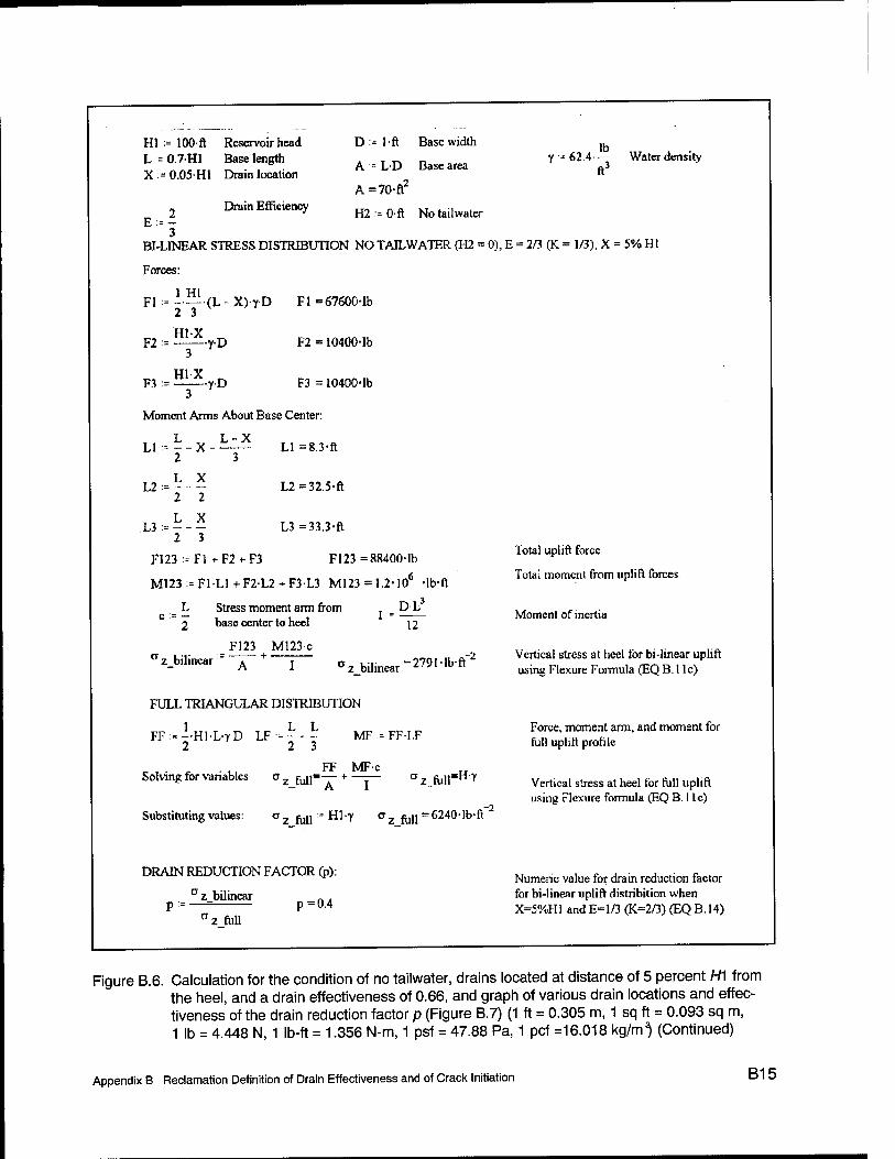
Hl := 100 ft Reservoir head L = 0.7H1 Base length X = 0.05H1 Drain location
Drain Efficiency
D-l-ft Base width
A := L-D Base area
A=70-ft2
H2:=0-ft Notailwater
IK y ■- 62.4— Water density
ft3
E,2- 3
BI-LINEAR STRESS DISTRIBUTION NO TAILWATER (H2 = 0), E = 2/3 (K = 1/3), X = 5% HI
Forces:
1 HI Fl := --— (L - X)rD Fl = 67600-lb
2 3
F2 := y-D
F3 := y-D
F2 = 10400-lb
F3 = 10400-lb
Moment Arms About Base Center:
LI = 8.3-ft 3
L X
2 3
L2:=:
2 3
L2=32.5-ft
L3=33.3-ft
F123 = Fl +F21-F3 F123 =88400-lb
M123=F1L1+F2-L2 + F3L3 M123 =1.2-10 -lb-ft
_ L Stress moment arm from . _ PL " 2 base center to heel \2
a z bilinear F123 M123c
I °z bilinear = 279I-lb-ff
FULL TRIANGULAR DISTRIBUTION
MF = FFI.F
FF MFc
1 L L FF:=--Hl'L-rD LF:=---
2 2 3
Solving for variables CTzfull"T~ + — A 1
az fuirH?
Substituting values: °zfiill:=Kl-7 <^z fan =6240- lb-ft
DRAIN REDUCTION FACTOR (p): az bilinear
-2
P = °Z fall
p=0.4
Total uplift force
Total moment from uplift forces
Moment of inertia
Vertical stress at heel for bi-linear uplift using Flexure Formula (EQ B.l lc)
Force, moment arm, and moment for full uplift profile
Vertical stress at heel for full uplift using Flexure formula (EQ B. I lc)
Numeric value for drain reduction factor for bi-linear uplift distribition when X=5%H1 and E=l/3 (K=2/3) (EQ B. 14)
Figure B.6. Calculation for the condition of no tailwater, drains located at distance of 5 percent H1 from the heel, and a drain effectiveness of 0.66, and graph of various drain locations and effec- tiveness of the drain reduction factor p (Figure B.7) (1 ft = 0.305 m, 1 sq ft = 0.093 sq m, 1 lb = 4.448 N, 1 lb-ft = 1.356 N-m, 1 psf = 47.88 Pa, 1 pcf =16.018 kg/m') (Continued)
Appendix B Reclamation Definition of Drain Effectiveness and of Crack Initiation B15

BUREAU OF RECLAMATION Drain Reduction Factor (p)
<D C\J I
o T- +* X D m <s ^ X. X <D A IE *_ o (0 (0
o V) r (0
r co <o 5 w
■n (0 0) 4-»
CO CO CD
a Tl y CO a CD CD ,f~ £ ^
o § "in
01 CO
DC ID
1-
\ 1.1 ~~"^ 1.2
/ /
/ i.
\ /
0.7 \
\ 0.8
N 0.9 \
/ 1.1
\ \ ,\ \
\
V V ̂ ^ N \ °" \
0.6
\ \
\ 0.7
\ 0.8
\
\ 0.9
\ \ s \ 1 v
\\
\
\x \ \ \ U.l
a-
\ 0.2
\ N 0.3 0;
^4 \
1 0.3
\ \ \
0.6
\ 0.7
\
\ 0.8
\
\ 0.9
\ ^ 0.1 0.2 03 0.4 0.5 0.6 0.7 0.8 0.9
Ratio of the drain location to the base length (Xd/L)
P rocGd U TG' 1. Calculate ratios (Xd/L) and (H3-H2)/(H1-H2) 2. Obtain value of p from graph 3. Correctp for taflwater using equation [p(Hl-H2)+H2]/H1
Where: p = drain reduction factor Hi = reservoir pressure head on the upstream face H2 = taHwater pressure head on the downstream face H3 = pressure head at the line of the drains Xd = distance of the drain from the upstream face L = horizontal length from upstream to downstream face-
Figure B.6. (Concluded)
B16 Appendix B Reclamation Definition of Drain Effectiveness and of Crack Initiation
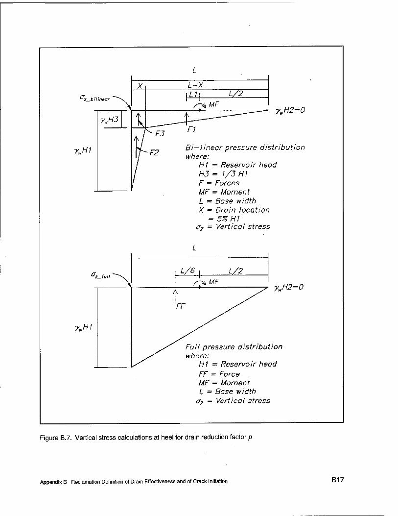
.bilinear
7„H1
7wH3
ywH1
ywH2=0
Bi—linear pressure distribution where:
H1 = Reservoir head H3 = 1/3 HI F = Forces MF = Moment L = Base width X = Drain location
- 5% H1 crz = Vertical stress
ywH2=0
Full pressure distribution where:
H1 = Reservoir head FF = Force MF - Moment L = Base width
o7 - Vertical stress
Figure B.7. Vertical stress calculations at heel for drain reduction factor p
Appendix B Reclamation Definition of Drain Effectiveness and of Crack Initiation B17
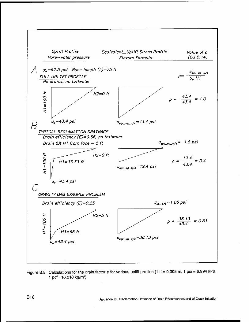
Uplift Profile Equivalent-Uplift Stress Profile Pore-water pressure Flexure Formula
Value of p (EQ B. 14)
^ yw=62.5 pcf, Base length (L)=75 ft
FULL UPLIFT PROFILE P= No drains, no tailwater
7. HI
o o
H2=0 ft 43A 1 n P= -43Ä =1-°
B uw=43.4 psi <W_up_„/s=4J-4 Psi
TYPICAL RECLAMATION DRAINAGE Drain efficiency (E)=0.66, no tailwater
Drain 5% HI from face = 5 ft Ceqv_Up_<iA = -1-8 Ps!
o o
H2=0 ft
<r«,y_uP_u/s= 19.4 psi
19-4 p = = 0.4
43.4
c uw=43.4 psi
GRAVITY DAM EXAMPLE PROBLEM
Drain efficiency (E)=0.25 Vup_d/s= 1-05 psi
H2=5 ft 36.13 na, p = -^- = 0.83
^-«P-uA^e-iSps'
Figure B.8. Calculations for the drain factor p for various uplift profiles (1 ft = 0.305 m, 1 psi = 6.894 kPa, 1 pcf =16.018 kg/m3)
B18 Appendix B Reclamation Definition of Drain Effectiveness and of Crack Initiation

the ratio (H3 - my (HI - H2) is (33 - 0)/(100 - 0) = 0.33, p from the graph is 0.4, the correction for tailwater is \p(Hl - HI) + H2]/H1 = [0.4(100 - 0 + 0]/100 = 0.4. So the value of p is 0.4.
The value of p for the example gravity dam in Figure 20 (main text) is included in Figure D.I. In this example, the calculated value ofp is 0.83 for HI = 100 ft, L = 75 ft, xd = 10 ft, H3 = 68 ft, and HI = 5 ft. Using the graph in Figure B.6, the ratio xd/L is 10/100 = 0.10, the ratio (H3 - H2)/(H1 - HI) is (68 - 5)/(100 - 5) = 0.663,/? from the graph is 0.82, the correction for tailwater is \p(Hl - HI) + H2]/m = [0.82(100 - 5) + 5]/100 = 0.83. So the value ofp is 0.83.
B.5 Reclamation Procedure to Determine Crack Initiation
Reclamation uses the following steps to determine when a crack initiates:
a. Determine all forces on the dam such as concrete weight, reservoir (hydrostatic), tailwater (hydrostatic), silt, ice, and uplift.
b. Determine moment arms for each force about the center of the uncracked base. In this case a crack has not formed so the moments are about the center of the base.
c. Determine the moments each force creates about the center of the base.
d. Calculate the total vertical normal stress oTota, at the heel using flexure formula in Equation B.llb. This is for all the forces without uplift.
e. Calculate the minimum allowable compressive stress a2U using Equation B. 12.
/. Compare oTolalHee, with the oz„. If om is larger, a crack will form.
Appendix B Reclamation Definition of Drain Effectiveness and of Crack Initiation B19

Appendix C Stability Calculations Made ofa100-ft-(30.5-m-)High Concrete Gravity Dam Section Using the Corps Engineering Procedure and the Corps Uplift Pressure Distribution
This appendix lists the derivation of the base pressure equation (given in terms of effective stresses) used in the Corps guidance and outlines the calculations made for a 100-ft- (30.5-m-) high concrete gravity dam section shown in Figure C.l. The Corps methodology to calculate crack potential and crack extent is demonstrated.
C.1 Fundamental Assumption of a Linear Base Pressure Distribution
Consider a structure resting on a solid foundation such as rock with a base of length L and width w (see the free-body diagram in Figure C.2). Let all the verti- cal forces applied to the base, including uplift, be N. Also, let M be the sum of all the moments applied to the base about the center of the base. As the base is in static equilibrium, the foundation applies an equal and opposite resisting force and moment in the form of base pressure. For a rigid base the pressure applied to the base from the foundation is assumed to take the linear form
P> = ax' + b <C1)
Appendix C Stability Calculations Using Corps Engineering Procedure and Uplift Pressure Distribution C1

o o
E o
Crest width d = 5 ft
Slope 0.7:1
Drain Gallery
Heel
Tailwater depth > f
V H2 = 5 ft
Drain statistics
Effectiveness E = 0.25
Distance from heel x. 10 ft
Height above base H4 = 10 ft
Base width L = 75 ft joe
uE= 10 = Yw(10 ft)
E = 1.0
Material prope rties
Concrete dens ity 150 DCf
Water d ensity 62.5 pcf
H2 'w 2
0 = 312.5 psf
UH3 = ^w H3 = 4'250 Psf
uE = 0 = Yw (87.33 ft)
uH1 = Yw H, = 6,250 psf
H, = 68 ft by Corps Criteria (from Figure 8)
Figure C.1. Gravity dam example problem using Corps uplift criteria with full base contact (1 ft = 0.305 m, 1 psf = 47.88 Pa, 1 pcf = 16.018 kg/m^
C2 Appendix C Stability Calculations Using Corps Engineering Procedure and Uplift Pressure Distribution
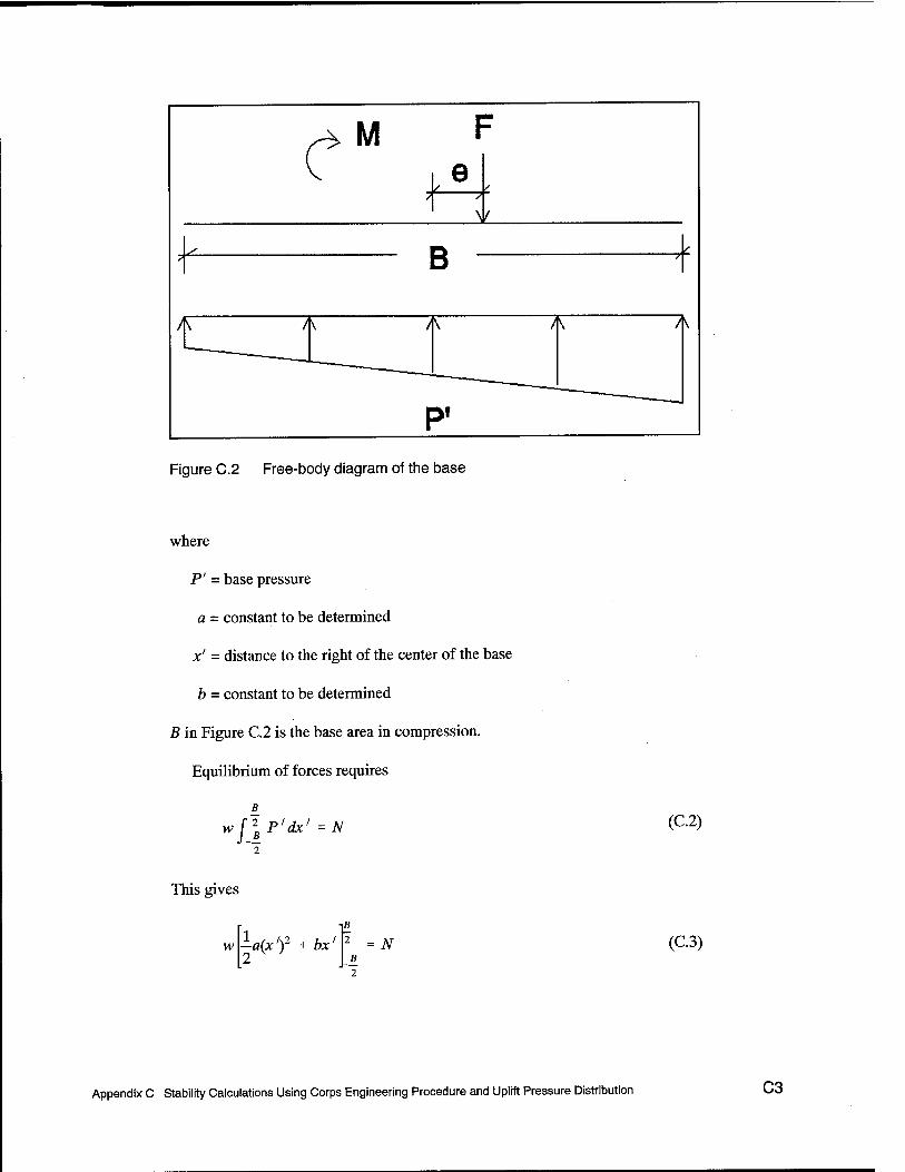
Figure C.2 Free-body diagram of the base
where
P' = base pressure
a = constant to be determined
x' = distance to the right of the center of the base
b = constant to be determined
B in Figure C.2 is the base area in compression.
Equilibrium of forces requires
B
W feP'dx' = N (C.2)
This gives
w -a(xf + bx' 2
B 2
£ 2
N (C.3)
Appendix C Stability Calculations Using Corps Engineering Procedure and Uplift Pressure Distribution C3

So
b = N
Bw (C.4)
Equilibrium of moments requires
w [l P'x'dx1 = M (C.5)
This gives
w -a(xf + -b(x)2
3 2
iß 2 = M
B_ 2
(C.6)
Thus
a = Y2M
B3w (C.7)
The base pressure becomes
P' = JC' + B3w Bw
(C.8)
From the definition
M N
(C.9)
where e = eccentricity, it can be written
P> = JL Bw x' + 1 B2
(CIO)
C.2 Cracking Condition
No cracking will occur while the base pressure remains positive. In the following sample problem, the headwater is on the left, so the most critical place on the base is at the left end. Therefore,
C4 Appendix C Stability Calculations Using Corps Engineering Procedure and Uplift Pressure Distribution

N
Bw
This yields
12e\_B\+1
B2 I 2 ' > 0 (Cll)
e < - (C12) 6
which leads to the general conclusion that the resultant must lie within the middle third of the base.
C.3 Sample Problem of a 100-ft-high Gravity Dam
The sample problem, given in Figure C.3, consists of a nonoverflow dam with a drain of effectiveness E which is higher than the tailwater level. The values of the variables are given in Table C.l. Note that a 1-ft (0.3-m) cross section is considered.
C.3.1 Test for crack
Equations C.9 and C.12 are used to test for the development of a crack where initially B =L.
C.3.1.1 Force computation. The weight of the structure W is
W = ^ic{d + L)H,w
(C 1 ^ = 1(0.15X5 + 75)(100)(1)
= 600 kip (2,668.8 kN)
where yc is the unit weight of the concrete.
The tailwater intersects the dam at
H2 xT = (d - L)— + L
(5-75)l4'+75 (C.14)
= 71.5 ft (21.8 m)
Appendix C Stability Calculations Using Corps Engineering Procedure and Uplift Pressure Distribution C5

Figure C.3. Sample problem
C6 Appendix C Stability Calculations Using Corps Engineering Procedure and Uplift Pressure Distribution

Table C.1 Value of Variables
Crest width d 5ft Length of base L 75 ft
Reservoir head H, 100 ft Tailwater height H, 5ft
Gallery height H4 10ft Distance of drain from heel K,
10ft
Density of water y„ 0.0625 kip/ft3 Unit weight of concrete y„ 0.15 kip/ft3
Drain effectiveness E 0.25 Width of base w 1ft
Note: 1 ft = 0.305 m; 1 kip/ft3 = 0.016018 kg/m3.
The vertical water load Vw is therefore
Vw - f[JL - xT)H2w
= -(0.0625)(75 - 71.5)(5)(1) (C.15)
= 0.55 kip (2.4 kN)
where yw is the unit weight of water.
The pressure head H'3 at x = xd if there is no drain or E = 0 from Figure C.4 is
= (100 - 5)
L - x,
L - r,
75 - 10
+ Ho
+ 5 (C.16)
75-0
= 87.33 ft (26.6 m)
where
xd = distance of the drain from the heel
T = current length of the crack
As the condition
H,<HA< Hi (C.17)
Appendix C Stability Calculations Using Corps Engineering Procedure and Uplift Pressure Distribution C7

Figure C.4. Pressure head H3' with no drain or E= 0
holds, the pressure head H3 at x = xd with the drain (see Figure C.5) is
H3 = {Hi - H4)(l -E)+HA
= (87.33 - 10)(1 - 0.25) + 10
= 68 ft (28.7 m)
The uplift force in Region 1 of Figure C.6 is
= (0.0625)(1)(100)(0)
= 0 kip
The uplift force in Regions 2 and 3 is
(C.18)
(C.19)
C8 Appendix C Stability Calculations Using Corps Engineering Procedure and Uplift Pressure Distribution

Figure C.5. Pressure head H3 with E= 0.25
U2, - ^ + H,){xd - T)
= i(0.0625)(l)(100 + 68)(10 - 0)
= 52.5 kip (233.5 kN)
The uplift force in Regions 4 and 5 is
-(0.0625)(1)(68 + 5)(75 - 10)
148.28 kip (659.5 kN)
(C.20)
(C.21)
Appendix C Stability Calculations Using Corps Engineering Procedure and Uplift Pressure Distribution C9

Figure C.6. Five regions of the uplift diagram with pressure heads identified at key points
The total uplift force is therefore
u = ux + u23 + u45
= 0 + 52.5 + 148.28
= 200.78 kip (893 kN)
The total force is therefore
(C.22)
N = W + VT - U
600 + 0.55 - 200.78
399.77 kip (1,778.2 kN)
(C.23)
C.3.1.2 Moment computation. All moments are taken about the center of the base. The moment due to the weight of the structure for Region 1 in Figure C.7 is
C10 Appendix C Stability Calculations Using Corps Engineering Procedure and Uplift Pressure Distribution

Figure C.7. Structure regions
Mwl = -icv>dHx
( d _ B T^
(0.15)(1)(5)(100) 1-21 -o (C.24)
-01 ,2 2 J
= -2,625 kip-fi (-3,559 tAT-m)
The moment due to the weight of the structure for Region 2 in Figure C.7 is
1 Mw2 = ftc»V - W i(2i + L) - - - T
3V 2
= |(0.15)(1)(75 - 5)(100)|i[2(5) + 75]
= -4,812.5 kip-fi (-6,525 JHV-m)
The total moment due to the weight of the structure is
75 (C.25)
Appendix C Stability Calculations Using Corps Engineering Procedure and Uplift Pressure Distribution C11

Mw = Mwl + Mw2
= -2,625 - 4,812.5
= -7,437.5 kip-ft (-10,083 kN-m)
The moment from the vertical water load is
Mx =V„ -(2L + xT) - — - T 3 T 2
1, (0.55) |[2(75) + 71.5] -T-°l
= 19.98 kip-ft (27 kN-m)
The moment from the upstream horizontal water load is
M2 = gYXW
= -(0.0625)(100)3(1) 6
= 10,416.67 kip-ft (14,123 kN-m)
The moment from the downstream horizontal water load is
M3 = —^Ijll™
= -^(0.0625)(5)3(1) o
= -1.30 kip-ft (-1.76 kN-m)
The moment due to uplift from Region 1 of Figure C.6 is
Ki = yjvHj B +T-L
. 2 2
= (0.0625)(1)(100)(0)
= 0 kip-ft (0 kN-m)
The moment due to uplift from Region 2 is
f- + 0 - »I I 2 2j
(C.26)
(C.27)
(C.28)
(C.29)
(C.30)
C12 Appendix C Stability Calculations Using Corps Engineering Procedure and Uplift Pressure Distribution
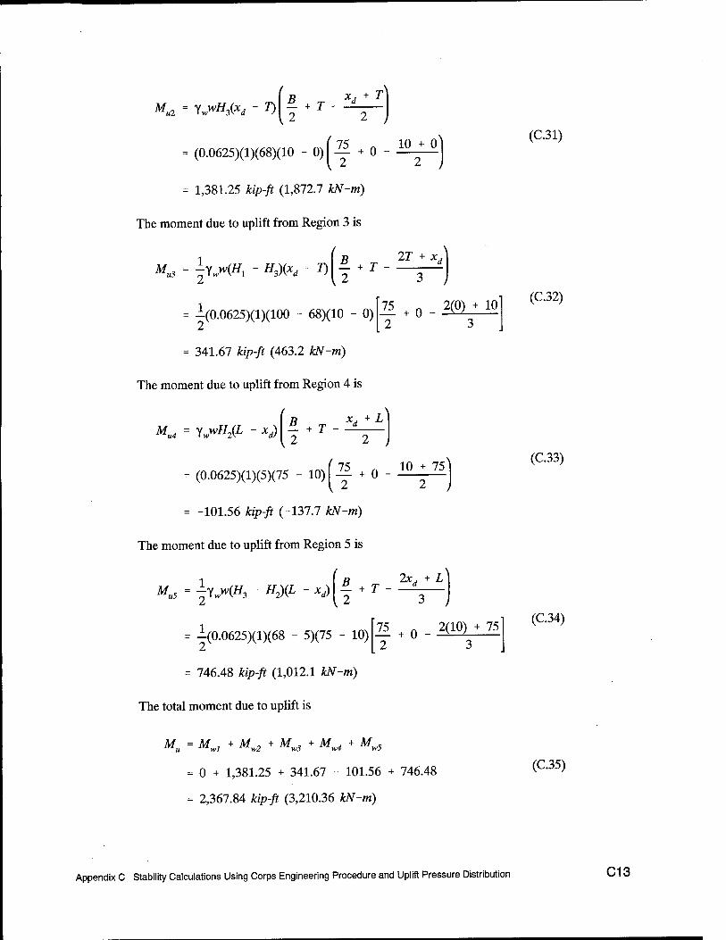
MU2 = ywwHPä - T)
R X. + l E_ + T - —
12
I 2 = (0.0625)(1)(68)(10 - 0)
= 1,381.25 kip-ft (1,872.7 kN-m)
The moment due to uplift from Region 3 is
75 +0_10j_0
M, * f Y^i - "aX*, - I)
1.
£ + r 12
= -(0.0625)(1)(100 - 68)(10 - 0)
= 341.67 kip-ft (463.2 kN-m)
The moment due to uplift from Region 4 is
2T + ^
3 J 75 + o - i 2
>(0) +10" 3
Mu4 = Yw>vH2(L - xd) E- + r - _*— 12
^ + 0 2
= (0.0625)(1)(5)(75 - 10)
= -101.56 kip-ft (-137.7 kN-m)
The moment due to uplift from Region 5 is
10 + 75
Mu5 = ^(//3 - HJff. - xd) B 2xj + L £. + r - _2—
75 +0 2(10) + 75 2 3
= i(0.0625)(l)(68 - 5)(75 - 10)
= 746.48 kip-ft (1,012.1 kN-m)
The total moment due to uplift is
Mu = Mwl + Mw2 + Mw3 + Mw + Mw5
= 0 + 1,381.25 + 341.67 - 101.56 + 746.48
= 2,367.84 kip-ft (3,210.36 kN-m)
(C.31)
(C.32)
(C.33)
(C.34)
(C.35)
Appendix C Stability Calculations Using Corps Engineering Procedure and Uplift Pressure Distribution C13

The total moment is therefore
M = Mw + M1 + M2 + M3 + Mu
= -7,437.50 + 19.98 + 10,416.67 - 1.30 + 2,367.84 (C36)
= 5,365.69 kip-fl (7,274.9 IcN-m)
C.3.1.3 Crack test. Equations C.9 and C. 12 can now be used to evaluate the existence of a crack.
M e = —
N
= 5,365.69 (C37)
399.77
= 13.42 ft (4.09 m)
As
e = 13.42 ft > - = — = 12.5 ft (3.81 m) (C.38) 6 6
a crack will develop.
C.3.1.4 Crack length. From Equation CIO the base pressure becomes zero at
(C.39) /_ B2
0 12e
From this a new value of the effective base becomes
B = I B u - x' (C40) new r% old U
and the new crack length is
T =L -B (C41) new new
C14 Appendix C Stability Calculations Using Corps Engineering Procedure and Uplift Pressure Distribution

C.3.2 Results for 7= 4 ft (1.22 m)
C.3.2.1 Force computation.
H3 ~ (Hl ~ H2>
(100 - 5)
L - x,
L - T
75 - 10 ^75-4
= 91.97 ft (28.03 m)
+ #,
+ 5 (C.42)
H3 = (Hi - HA)(1 -E) +H4
= (91.97 - 10)(1 - 0.25) + 10
= 71.48 ft (96.91 in)
(C.43)
= (0.0625)(1)(100)(4)
= 25 kip (111.2 iUV)
(C.44)
U23 = ^YM^ + ^3)fe - T)
-(0.0625)(1)(100 + 71.48X10 - 4)
= 32.15 fo> (143.0 kN)
U45 = ^Y^(//3 + HJ(L - *d)
= -(0.0625)(1)(71.48 + 5)(75 - 10)
155.35 kip (691.0 kN)
(C.45)
(C.46)
u = u1+u23 + u45
= 25 + 32.15 + 155.35
= 212.5 kip (945.25 kN)
(C.47)
Appendix C Stability Calculations Using Corps Engineering Procedure and Uplift Pressure Distribution C15

N = W + VT - U
= 600 + 0.55 - 212.5
= 388.05 kip (1,726.13 kN)
(C.48)
C.3.2.2 Moment computation.
Mwl = ycwdHr d B
^2 2
= (0.15)(1)(5)(100)(| - 21 _4J
= -2,775 **>/* (-3,762.4 iUV-m)
(C.49)
M. H>2
±ycw(L - dyH, l(2d + L) - - 3 2
■|(0.15)(1)(75 - 5)(100)£[2(5) + 75]
-5,862.5 kip-ft (-7,948.5 kN-m)
|[2(5) + 75] - 21 - 4J (C.50)
^. = ^ + MW2
-2,775 - 5,862.5
-8,637.5 kip-ft (-11,710.9 kN-m)
(C.51)
Mx =VH 1(2L + xT) - — - T 3 T 2
# (0.55) ^[2(75) + 71.5] - 21
= 18.88 kip-ft (25.6 kN-m)
(C.52)
C16 Appendix C Stability Calculations Using Corps Engineering Procedure and Uplift Pressure Distribution

K = WHxT 1 + T-L U
(0,0625)(1)(100)(4) — +4 l 2
= 937.5 kip-ft (1,271.1 kN-m)
K2 = Y^ftr - *) £. + r - -2 12
= (0.0625)(1)(71.48)(10 - 4) 71 „ — + 4 l 2
10+4
= 871.16 kip-ft (1,181.1 JUV-Ji!)
(C.53)
(C.54)
**« = ^Y^ - H3)(xd - 7) £ + T 2
IT + Xj
i(0.0625)(l)(100 - 71.48)(10 - 4)
179.14 kip-ft (242.9 kN-m)
21 + 4 - 2(4) + 10l (C'55)
K4 - ywwHJL - xd) B x.+L tL + T - —
^ 2 2
= (0.0625)(1)(5)(75 - 10) | 21 + 4 - i^J5
= -60.94 kip-ft (-82.6 kN-m)
(C.56)
K5 - ^3 - W - **> 5 + r — «* 2*,, + L
{2
■ 71 , . 2(10) + 75^ (Q5?) = A(0.0625)(l)(71.48 - 5)(75 - 10)1 -^ + 4 - -^ J
= 1,057.79 kip-ft (1,434.2 JÜV-ro)
Appendix C Stability Calculations Using Corps Engineering Procedure and Uplift Pressure Distribution C17

K = Mwl + Mw2 + Mw3 + Mw4 + Mw5
= 937.5 + 871.16 + 179.14 - 60.94 + 1,057.79
= 2,984.65 kip-ft (4,046.6 kN-m)
M = Mw + Mt + M2 + M3 + Mu
= -8,637.5 + 18.88 + 10,416.67 - 1.30 + 2,984.65
= 4,781.4 kip-ft (6,482.7 kN-m)
(C.58)
(C.59)
e = M N
= 4,781.4
388.05
= 12.32 ft (3.76 m)
/ -. -ll-
712
12(12.32)
= -34.1 ft (-10.39 m)
«en - 1 R r'
- \ (75) - (-34.1)
= 71.6 ft (21.82 m)
T = L - B new new
= 75 - 71.6
= 3.4 ft (1.04 m)
(C.60)
(C.61)
(C.62)
(C.63)
C18
C.3.2.3 Final solution. Equations C.42-C.63 can be repeated iteratively with T set to Tnew until convergence of T (T„ew remains unchanged within an
Appendix C Stability Calculations Using Corps Engineering Procedure and Uplift Pressure Distribution

Table C.2 Iteration Results
Iteration 7"n.wjft U,Mp M„ kip-ft W,kip M, kip-ft
1 2.58 200.78 2,367.84 399.77 5,365.69
2 4.41 208.33 2,763.25 392.22 4,987.61
3 5.69 213.71 3,049.44 386.84 4,721.74
Solution 8.23 224.90 3,654.04 375.65 4,180.36
Note: 1 ft = 0.305 m; 1 kip = 4,448 kN; 1 kip-ft = 1.356 kN-m.
acceptable tolerance). Table C.2 shows results for three iterations and then the converged solution.
By Equation C.9
e = M. = n.128 ft (3.392 m) N
(C.64)
Also, from Equation CIO the maximum base pressure can now be computed as
P' N \2e{ B)
+ 1 Bw [B2{ 2) \
1 ( 6M , „) w(L -T) U - T >
(1X75 - 8.23)
= 11.25 kip/ft2 (538.65 kPa)
6(4,180362 + 375 65
75 - 8.23
(C.65)
C.4 Determine Reservoir Elevation When the Crack Initiates
Equations C.9 and C.12 with B = L are combined to determine the reservoir elevation that initiates the crack as follows:
- = 12.5 ft (3.81 m) 6
(C.66)
Appendix C Stability Calculations Using Corps Engineering Procedure and Uplift Pressure Distribution C19

Hx is determined by substituting different values of Ht into Equations C.13-C.36 with T = 0 and all other values of Table C.l remaining the same until Equa- tion C.66 is satisfied. This iterative process produces a value of Hlcr = 98.97 ft (30.17 m). Equation C.16 can now be used to compute
H3cr ~ (Hlcr ~ Hl)
(98.97 - 5)
' L - Xj
[L -T)
( 75 - 10^
k 75 - 0 )
+ H,
+ 5
86.44 ft (26.35 m)
Finally, from Equation C.18,
(C.67)
H3cr = (HL - #4)(1 " E) * HA
= (86.44 - 10)(1 - 0.25) + 10
= 67.33 ft (20.52 m)
(C.68)
C20 Appendix C Stability Calculations Using Corps Engineering Procedure and Uplift Pressure Distribution

Appendix D Stability Calculations Made of a100-ft-(30.5-m-)High Concrete Gravity Dam Section Using the Reclamation Engineering Procedure and the Corps Uplift Pressure Distribution
D.1 Concrete Gravity Dam Example
The following example concrete gravity dam problem will be used to demon- strate three cases showing the procedure Reclamation uses to determine cracking in a gravity dam. This appendix describes the methodology to calculate crack potential and crack extent. The uplift profile will be identical to the Corps calcu- lations in Appendix C, so only the cracking methodology is demonstrated. In Appendix E, Reclamation criteria for uplift will be used to demonstrate the differences in uplift assumptions. The calculations will be performed using MathCad (MathSoft, Inc.).1 The first case will show the calculations to determine the potential for cracking with a reservoir depth (H^) of 100 ft (30.48 m). The second case will show the calculations to determine the depth of reservoir for a crack to initiate. The third case will show the calculations to determine how far a crack will propagate with the reservoir depth at 100 ft (30.48 m).
The example problem is a concrete gravity dam with the following dimensions, loads, and drainage (Figure D.l).
1 References cited in this Appendix are included in the References at the end of the main text.
Appendix D Stability Calculations Using Reclamation Engineering Procedure and Corps Uplift Pressure Distribution D1

Dam height Hd 100 ft (30.48 m) Base width L 75 ft (22.86 m) Uncracked base width B 75 ft for case 1 and 2,
calculated for case 3 Crest width d 5ft (1.52 m) Downstream slope (run:rise) 0.7:1 Reservoir height H1 100 ft (30.48 m) for case 1 and 3,
calculated for case 2 Tailwater height H2 5 ft (1.52 m) Crack length T 0 ft (0 m) for case 1 and 2,
calculated for case 3 Pressure head at the drain H3 calculated using Corps criteria
(See Appendix A) Drain effectiveness E 0.25 Distance drain from heel xd 10 ft (3.05 m) Drain height above base H4 10 ft (3.05 m) Concrete density 150 lb/ft3 (2,402.77 kg/m3) Water density yw 62.5 lb/ft3 (1,001.15 kg/m3) Sign convention: Tensile stress is positive.
Compressive stress is negative.
D.2 Potential for Cracking with 100-ft (30.48-m) Reservoir Depth H,
The first example calculations determine cracking potential for a reservoir depth of 100 ft (30.48 m) using Reclamation criteria (Figure D.2). The following is a narrative of the calculations.
a. Determine force components. Calculate force components for the weight of concrete, reservoir load, tailwater load, and uplift load (Figures D.2 and D.3). Force components are designated Wfor the concrete weight, R for the reservoir, TW for the tailwater, and U for the uplift. The uplift profile is a bilinear distribution from full reservoir head at the heel to head at the drain H3 to full tailwater head at the toe. Reclamation assumes different head reduction at the drain from that of the Corps. However for this study, the Corps criteria will be used for H3.
b. Determine moment arms and moments about uncracked portion of the base. Calculate the moment arms and moments for all the force compo- nents about the uncracked portion of the base (Figures D.2 and D.3). Moment arms are designated with anZ, and the force designation (i.e., LR is the moment arm for the reservoir load). Moments are designated M and the force designation (i.e., MR is the moment induced by the reservoir load).
c. Equivalent effective stress at the heel (includes uplift). If zero tensile strength of concrete/, is assumed, the equivalent effective stress at the
Appendix D Stability Calculations Using Reclamation Engineering Procedure and Corps Uplift Pressure Distribution

heel and toe can be calculated in lieu of using a2U (indicated in the figures in this appendix as Szu) to determine the cracking potential. The equivalent effective stress is calculated using the flexure formula and all the force components (W, R, TW, and U) (Figure D.2, Sheet 2). In this case, the equivalent effective stress at the heel is 2.73 lb/in2 (18.82 kPa) tension. A crack is postulated to initiate since this equivalent effective stress is tension (greater than zero).
Calculate om and check for crack initiation. The ozu method is identical to the equivalent effective stress method with zero tensile strength of con- crete (Figure D.2). Reclamation criteria state two values of the drain factory of 1.0 and 0.4. This example uplift profile does not match either of these stated uplift profiles, so a new value ioxp must be calculated. First, the equivalent uplift stress at the heel is calculated using the uplift forces and the flexure formula, which equals 36.13 lb/in2 (249.1 kPa) (Equation B.llc). Second, the equivalent uplift stress at the heel from a full uplift profile with full reservoir head at the heel, no drains, and no tailwater is calculated using the flexure formula, which equals 43.4 lb/in2
(299.2 kPa) and is always ywH1 (Equation B.llc). The drain reduction factor is 36.13 lb/in2 divided by 43.4 lb/in2 (299.2 kPa), which equals 0.83 (Equation B.14). Third, the total stress is calculated using all forces (W, R, and TW) without uplift U, which equals 33.4 lb/in2 (230.3 kPa) compression (Equation B.llb). Fourth, the total stress of 33.4 lb/in2
(230.3 kPa) compression is compared with o2U of 36.13 lb/in2 (249.1 kPa) tension. A crack is postulated to form since the tension is greater than the compression. Figures B.5 and D.4 graphically show the stress profiles for this example.
D.3 Determine Reservoir Elevation When Crack Initiates
The second set of example calculations determines the reservoir depth Hx
when cracking initiates using Reclamation criteria (Figures D.5 and D.6). The calculations to determine the reservoir depth when cracking initiates is an iterative process and is identical to the previous calculations with reservoir depth equal to 100 ft (30.48 m). The reservoir elevation H1 is varied until the total vertical normal stress at the heel equals o^ For this example, the reservoir level to initiate cracking is 98.9675 ft (30.16 m).
Appendix D Stability Calculations Using Reclamation Engineering Procedure and Corps Uplift Pressure Distribution D3

D.4 Determine Depth of Cracking with Reservoir Elevation H, of 100 ft (30.48 m)
The third set of example calculations determines the horizontal extent of cracking T with the reservoir depth Hl of 100 ft (30.48 m) using Reclamation cri- teria (Figures D.7 and D.8). The calculation to determine the reservoir depth when cracking initiates is an iterative process, because the uplift profile changes as the crack grows. The calculations are similar to the previous calculations with reservoir depth equal to 100 ft (30.48 m). The crack length T is varied until the equivalent effective stress at the crack tip is zero. For this example, the calculated depth of cracking is 8.23 ft (2.51 m). o^ is not used in the depth of cracking calculations.
D4 Appendix D Stability Calculations Using Reclamation Engineering Procedure and Corps Uplift Pressure Distribution

Crest width d = 5 ft
Slope 0.7:1
Drain Gallery
H1 Heel
Tailwater depth > f
V H2 = 5 ft
Ci>
Base width L = 75 ft joe
Drain statistics
Effectiveness E = 0.25
Distance from heel x, = 10 ft
d
Height above base H4 = 10 ft
u E = ,.0 = TU 10 ft) E = 1.0
Material properties
Concrete density 150 pcf
Water d 62.5
ensity pcf
UH2 'w 2
0 = 312.5 psf
UH3 = Yw H3 = 4>250 Psf
uE = 0 = Yw (87.33 ft)
uH1 = Yw H, = 6,250 psf
H = 68 ft by Corps Criteria (from Figure 8)
Figure D.1. 100-ft-high gravity dam section (1 ft = 0.305 m, 1 pcf =16.018 kg/m3, 1 psf = 47.88 Pa)
Appendix D Stability Calculations Using Reclamation Engineering Procedure and Corps Uplift Pressure Distribution D5

Determine Potential for Crack Formation (Using Corps Uplift Criteria) (See Figures B.5, D. 1, D.3, and D.4)
GIVEN VARIABLES d=5-ft HI := 100.0-ft H4 := 10-ft
H2 = 5ft
yw .= 62.5-
T - 0.0ft
B=L-T
CTest width Reservoir height Gallery height Tailwater height
yc := 150- lb
xd
lb Density of water
ft"
10-ft
w:= 1-ft
E := 0.25
Concrete density
Drain distance Width into paper Drain efficiency
Slope - 0.7
He := 100-ft
D/S slope
Height of Dam
L = d+ He Slope L=75-ft Base length
Kips ■= 10001b
B=75-ft
CRACK LENGTH, T
Uncracked base width
DETERMINE FORCE COMPONENTS: Weight of Concrete
Wl ■= YC-d-Hc-w Wl=75-Kips
W2 = 0.5yc-Hc(L-d)w Wdam = Wl + W2
Tailwater TWv:= 0.5-ywH2SlopeH2w
TWh := 0.5-ywH2H2w
Uplift
W2= 525-Kips Wdam =600-Kips
TWv = 0.55-Kips
TWh =0.78-Kips
Concrete region 1 Concrete region 2 Total dam weight
Vertical tailwater Horizontal tailwater
L-xd -H2 Hp3:=<Hl-H2)-lL T
H3:=(Hp3-H4)(l-E)+H4
Ul := yw Hl-T-w
U2 = yw-H3(xd - T)-w
U3 = 0.5-yw(Hl - H3)-(xd - T)w
U23 = U2 + U3
U4=ywH2(L-xd) w
U5 = 0.5-yvv(H3 - H2)-(L - xd)w
U45 := U4 +■ U5
Utotal = Ul +■ U2 + U3 + U4 + U5
Reservoir Force
Hp3=87.33-ft
Head at drain, Corp criteria
Uplift region 1
Pressures:
H3 =68-ft
Ul =0-lb
U2 =42.5-Kips
U3 =10-Kips
U23= 52.5-Kips (EqC.20)
U4 =20.31-Kips
U5 = 127.97 -Kips
U45 = 148.28-Kips (EqC.21)
Utotal = 200.78 -Kips Total uplift force (EqC.22)
(EqC.13)
(EqC.15)
(EqC.16)
(EqC.18)
(EqC.19)
lHl
'H2
'H3
Hl-yw lHl = 43.4-
H2yw lH2 = 2.17-
_lb ~2 in
lb
= H3yw um =29.51 lb
• 2 in
R = 312.5 -Kips Horizontal reservoir force
DETERMINE MOMENTS ABOUT CENTER OF UNCRACKED PORTION OF THE BASE:
Kipft := 1000-lb-ft
MW1 = W1LW1 MW1 =2625 -Kipft
R := 0.5-yw-Hl -w
Concrete moments arms and moments d
LW1 ? + T 2 2
LW2 =-+T-d ■2
LW1 =35-ft
He- Slope LW2 =9.17-A MW2 = W2-LW2
(Eq C.24
MW2=4812.5-Kipft (EqC.25)
Figure D.2. Initial stability calculation of a gravity dam with full base contact following Reclamation procedures (1 ft = 0.305 m, 1 kip = 4.448 kN, 1 kip-ft = 1.356 kN-m, 1 pcf =16.018 kg/m * 1 psi = 6.894 kPa, 1 sq ft = 0.093 sq m) (Sheet 1 of 3)
D6 Appendix D Stability Calculations Using Reclamation Engineering Procedure and Corps Uplift Pressure Distribution

Determine Potential for Crack Formation (Using Corps Uplift Criteria) T - 0 ■ ft Tailwater moment arm and moment
LTWv = B /H2-Slope\
2 \ 3 (-1.0) LTWv=36.33-fl MTWv:- TWvLTWv c 2?
MTWv = 19.87 -Kipft
LTWh=~ LTWh = 1.67-ft MTWh - TWhLTWh MTWh = 1.3-Kipft (EqC.29) 3
Uplift moment arms and moment
LU1:=5 + I LUl=37.5-ft MUl-^Ul-LUl MU1 =0-Kipft (EqC.30) 2 2
LU2 ;= 5 - I^Lll) LU2=32.5-ft MU2 = U2LU2 MU2 = 1381.25-Kipft (EqC.31)
LU3 := - - /Xd " T) LU3 = 34.17-ft MU3 ■- U3-LU3 MU3 =341.67-Kipft (EqC.32) 2 \ 3
LU4:=5 + T-xd- [tli^] LU4=-5-ft MU4 := U4LU4 MU4 =-101.56-Kipft (EqC.33)
LU5 ;= ? + T _ xd - IhzJ^) LU5=5.83-ft MU5 = U5LUS MU5 =746.48-Kipft (EqC.34)
Reservoir moment arm and moment
LR=— LR=33.33-ft MR = R-LR MR = 10416.67-Kipft (EqC.28) 3
EQUIVALENT EFFECTIVE STRESS AT CRACK-TIP (INCLUDES UPLTFT), USING FLEXURE FORMULA: P/A + Mo/I ABOUT CENTERLINE OF UNCRACKED BASE
Sum of all Vertical Forces Fveqveff = Wl+W2 + TWv-Ul-U2-U3-U4-U5 Fveqveff= 3 99.77 -Kips (EqC.23)
Sum of all Moments about Centerline of Uncracked Base
Meqveff .= MW1 + MW2 + MTWh - MTWv- MU1 - MU2 - MU3 - MU4 - MU5 - MR
Meqveff=-5365.57 -Kipft (Eq C.36
c = — c =37.5-ft Location of crack-tip from center of Uncracked base 2
I ■- a 'w, i = 35156.25-ft4 Moment of Inertia of Uncracked Base 12
A = Bw A=75-ft2 Area of Uncracked Base
.reqveffcrackjip = [^gveff^ Meqveffc\_ ^ oeqve£r_elHÖk_tip =2.73 ._» (EQB.Ha) \ A I / in Positive = tension (If tension,
then crack grows)
oeqveff toe := ^^- *^*4(-1.0) aeqveff toe =-76.76 -^ (EqB 11a) \ A 1 I in2
Figure D.2. (Sheet 2 of 3)
Appendix D Stability Calculations Using Reclamation Engineering Procedure and Corps Uplift Pressure Distribution D7

Determine Potential for Crack Formation (Using the Corps Uplift Criteria)
CALCULATE Szu AND CHECK FOR CRACK INITIATION:
Calculate stress at crack tip and toe from Uplift forces only
T=0-ft
Fveqv_uplift := Ul + U2 1- U3 + U4 +■ U5
Meqvjiplift := MUl + MU2 + MU3 + MU4 + MU5
aeqv_uplift_crktip
oeqv_uplift_toe : =
Fveqv_uplift Meqv_uplift-c __ + -
Fveqv_uplift Meqv_uplift-c - -
Fveqvjiplift =200.78 -Kips
Meqvjiplift =2367.84 -Kipft lb
aeqv_uplift_crktip = 36.13 —-
aeqv_uplift_toe = 1.05 lb
(EqC.35)
(EqB.llc)
(EqB.llc)
Calculate stress at heel from full uplift profile = no tailwater, no drains Equivalent Triangular Uplift Distribution
lb oH1 := 1.0-yW'Hl ujjj=43.4—-
Calculate Drain factor (p) value in Szu=pgwh-ft/s
T = 0- ft Crack length (T), if T=0, then at heel
aeqv_uplift_erktip
in
s:= 1.0
UH1 lb
p =0.83
Tensile strength of concrete
Safety factor
Szu := p-yw-Hl s
Szu =36.13- lb
CALCULATE TOTAL STRESS (WITHOUT UPLIFT)
Fvjotal = Wl + W2 + TWv
Mtotal = MW1 + MW2 + MTWh - MTWv - MR
/Fv total Mtotal-c\ ototal_crktip =
olotal toe :
1.0
(-1.0)
p is the ratio of the stress at the heel from uplift profile in question divided by the stress at the heel from a full triangular uplift profile
Szu is the same as the vertical stress at the heel from the uplift profile in question when the tensile strength of concrete = 0 psi.
(EqB.12)
Fvjotal =600.55 »Kips
Mtotal =-2997.73 -Kipft
lb crtotal_crktip =-33.4 •
CTtotal toe =-77.81 •
in
lb
(EqB.llb)
(EqB.llb)
COMPARE TOTAL STRESS (WITHOUf UPLIFT) WITH Szu 2 -2
ctotal_crktip = -33.4 -lb in" Szu = 36.13 -lb in
Compare := CTtotal_crktip - Szu ( 1.0) Compare = 2.73-Ibin"
Cracking:If the total stress has a compression greater than Szu, then
_2 no crack develops.
Figure D.2. (Sheet 3 of 3)
D8 Appendix D Stability Calculations Using Reclamation Engineering Procedure and Corps Uplift Pressure Distribution
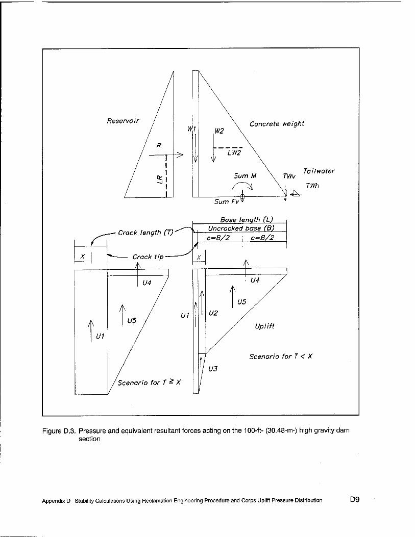
Reservoir / V/1
\ Concrete weight W2 \
/ R ^>
1 \ /W2
" i k \
/ et i ,. \ Tailwater
Sum M \ TWv / ~J
T i TWh 4±
Sum FvV j
Base lenqth (L)
— Crack length (T)'^~>^ Uncracked base (B) c=B/2 c=B/2
X i >\
X 1 ■*■— c rack tip — K
U4 /
t 1 \
U4 /
/ \
/ / ui
U5 U2
t/5 X
/ Uplift
U1
1 / Scenario h
'/ t/J
■>rT < X
/Scenario for T £ X /
Figure D.3. Pressure and equivalent resultant forces acting on the 100-ft- (30.48-m-) high gravity dam section
Appendix D Stability Calculations Using Reclamation Engineering Procedure and Corps Uplift Pressure Distribution D9

7w*H1=43.4-
Szu=36.13-
c ►5
2.73-
Heel
Determine if Cracking Forms, 1=0 ft
(Values in psi)
Equi\/alent_upiift stress profile
Full uplift, no tw, no drains
Uplift pressure
yw*H3=29.51
E o o
-33.4
\
\ y Equivalent-effect)ve (w/uplift)
\
Total stress (w/o Uplift)-
\
Legend:
Uplift profiles Stresses along base (base pressures)
7,*H2=
■2.17
1.05 0.00
Toe
-76.76
-77.81
Figure D.4. Minimum allowable compressive stress azu according to Reclamation criteria and assuming full base contact (1 psi = 6.894 kPa)
D10 Appendix D Stability Calculations Using Reclamation Engineering Procedure and Corps Uplift Pressure Distribution

Determine Reservoir Level to Induce Crack Formation (Using Corps Uplift Criteria) (See Figures B.5, D. 1, D. 3, and D.4)
GIVEN VARIABLES d:=5-ft Crest width HI =98.9675- ft RESERVOIR HT H4 := 10 ft Gallery height H2 - 5-ft Tailwalerheight
YW
yc 15o^
«,4 ft3
Density of water
ft
xd := 10'ft
w = 1-ft
E ■= 0.25
Concrete density
Drain distance Width into paper Drain efficiency
Slope := 0.7
Hc:= 100 ft
D/S slope
Height of Dam
L := d + He Slope L=75-ft Base length
Kips ■= 1000-lb
T := 0.0- ft
B =L-T B=75-ft
CRACK LENGTH, T
Uncracked base width
DETERMINE FORCE COMPONENTS: Weight of Concrete
Wl -- yc-d-Hc-w Wl =75 -Kips
W2 •= 0.5-yc He (L - d) w Wdam := Wl + W2
Tailwater TWv ■- 0.5-yw-H2- Slope H2w
TWh:=0.5ywH2H2w
Uplift
HP3 =(H1-H2)(^-^J+H2
H3=(Hp3-H4)(l -E)+H4
Ul = yw-H1 Tw
U2 := yw-H3 (xd - T) w
U3 := 0.5TW(H1 - H3)-(xd - T) w
U23:=U2^-U3
U4=yvvH2(L-xd)w
U5 := 0.5-YW-(H3 - H2)-(L - xd)w
U45 = U4+U5
Utotal := UI + U2 + U3 +■ U4 + U5
W2= 525-Kips Wdam =600-Kips
TWv =0.55 -Kips
TWh =0 78-Kips
Concrete region 1 Concrete region 2 Total dam weight
Vertical tailwater Horizontal tailwater
Hp3=86.44-ft
Head at drain, Corp criteria
Uplift region 1
Pressures:
H3 =67.33*ft
Ul = 0-lb
U2 =42.08-Kips
U3=9.89-Kips
U23=51.97-Kips (EqC.20)
U4= 20.31-Kips
U5= 126.61-Kips
U45 = 146.92-Kips (EqC.21)
Utotal = 198.89 -Kips Total uplift force
(EqC.13)
(EqC15)
(EqC.16)
(EqC.18)
(EqC.19)
lb UH1 = HI yw u^] =42.95-- in~
lb uH2'=H2yw uH2=2.17-—
in
lb UjQ-fflyw uH3 =29.22 ■—
Reservoir Force
R = 0.5-yw HI2 w
(EqC.22)
R = 306.08 -Kips Horizontal reservoir force
DETERMINE MOMENTS ABOUT CENTER OF UNCRACKED PORTION OF THE BASE:
Concrete moments arms and moments Kipft = 1000- lb- ft
LWl:= = + T-~ LWl=35-ft MW1=W1LW1 MW1 =2625-Kipft 2 2
W2LW2 MW2 =4812.5-Kipft (EqC.25)
? + T-d
2 2 B , He-Slope
LW2 := - + T - d — 2 3
MW1
LW2=9.17-ft MW2
(EqC.24
Figure D.5. Reclamation calculation to determine reservoir elevation H, resulting in Stotal „ee/equal to oZL
(1 ft = 0.305 m, 1 kip = 4.448 kN, 1 kip-ft = 1.356 kN-m, 1 pcf =16.018 kg/m* 1 psi = 6.894 kPa (Sheet 1 of 3)
Appendix D Stability Calculations Using Reclamation Engineering Procedure and Corps Uplift Pressure Distribution D11

Determine Reservoir Level to Induce Crack Formation (Using Corps Uplift Criteria) T = 0-ft Tailwater moment arm and moment
LTWv: -B /H2-Sloped
+ 2 I 3 I
(-1.0) LTWv = 36.33-ft MTWv = TWvLTWv Q
MTWv = 19.87-Kipft
LTWh:=— LTWh = 1.67-ft MTWh = TWhLTWh MTWh = 1.3 -Kipft (EqC.29) 3
Uplift moment arms and moment
UJ\ :?-■>■- LUl=37.5-ft MU1=U1LU1 MU1 =0-Kipft (EqC.30) 2 2
LU2 .-. 5 - h^l) LU2 =32.5-ft MU2 := U2LU2 MU2 = 1367.62 -Kipft (EqC.31)
LU3 ;= ? . f25lll) LU3 = 34.17-(t MU3 = U3LU3 MU3 =337.81 -Kipft (EqC.32) 2 \ 3
LU4:=5 + T-xd-(t^] LU4=-5-ft MU4 = U4-LU4 MU4 =-101.56-Kipft (EqC.33)
LU5 := 5 +. T - xd - (—--] LU5=5.83-ft MU5 ■-- U5-LU5 MU5 =738.53 -Kipft (EqC.34)
Reservoir moment arm and moment
LR= — LR=32.99-ft MR := R-LR MR = 10097.33-Kipft (EqC.28) 3
EQUIVALENT EFFECTIVE STRESS AT CRACK-TIP (INCLUDES UPLIFT), USING FLEXURE FORMULA: P/A + Mc/I ABOUT CENTERLINE OF UNCRACKED BASE (EQUATION B. 1 la)
Sum of all Vertical Forces Fveqveff := Wl + W2 + TWv - Ul - U2 - U3 - U4 - U5 Fveqveff=401.66 -Kips (Eq C.23)
Sum of all Moments about Centerline of Uncracked Base
Meqveff := MW1 + MW2 + MTWh - MTWv - MU1 - MU2 - MU3 - MU4 - MU5 - MR
Meqveff = -5020.79 -Kipft (Eq C.36)
c := — c = 37.5-ft Location of crack-tip from center of Uncracked base, (Eq D. 1) 2
R3
I := —- 1=35156.25-ft4 Moment of Inertia of Uncracked Base, (Eq D.2) 12
A = B w A = 75-ft2 Area of UncTacked Base, (Eq D.3)
/Fveqveff Meqveff <A ,. „ , .. „ lb Positive = tension Of tension, ceqveff_crackjip := {—^— - —*z 1.0 «reqveffcrackj.p =0 •— .. . .
\ A . 2 then crack grows) in
5cqvtCtoe:=(^™?-^^Wl.O) aeqveffjoe = -74.38--^ (EqB.lla) in2
Figure D.5. (Sheet 2 of 3)
D12 Appendix D Stability Calculations Using Reclamation Engineering Procedure and Corps Uplift Pressure Distribution

Determine Reservoir Level to Induce Crack Formation (Using Corps Uplift Criteria) CALCULATE Szu AND CHECK FOR CRACK INITIATION:
T=0-ft
Calculate stress at crack tip and toe from Uplift forces only
Fveqvuplift ; Ul + U2 + U3 + U4 + U5
Meqvjiplift = MU1 + MU2 + MU3 + MU4 + MU5
/Fveqv uplift Meqv_upliftc aeqvuphftcrktip - I- *
Fveqv_uplift = 198.89 -Kips
Meqv_iiplift =2342.4 -Kipft
oeqv_uplift_crktip = 35.77 ■ 2 in
/Fveqv uplift Mcqv_uplift c aeqv_uphft_toe := = aeqv_uplift_toc = 1.06 ■
lb
(EqC.35)
(EqB.llc)
(EqB.llc)
Calculate stress at heel from full uplift profile = no tailwater, no drains Equivalent Triangular Uplift Distribution
uH1:--1.0rwHl oH] =42.95 —- in
Calculate Drain factor (p) value in Szu=pgwh-ft/s
T = 0-ft Crack length (T), if T=0, then at heel
ereqv_uplift crktip p = -=
UH1 lb
(EqB.llc)
f,:=0- 1 2 in
s:= 1.0
p=0.83
Tensile strength of concrete
p is the ratio of the stress at the heel from uplift profile in question divided by the stress at the heel from a full triangular uplift profile (Equation B. 14)
Safety factor
Szu := p>yw-Hl Szu =35 77 lb
CALCULATE TOTAL STRESS (WITHOUT UPLIFT)
Fvjotal := Wl + W2 + TWv
Mtotal = MW1 + MW2 + MTWh - MTWv- MR
/Fv total Mtotal'cA
Szu is the same as the vertical stress at the heel from the uplift profile in question when the tensile strength of concrete = 0 psi.
(F.qB.I2)
Fvjotal =600.55-Kips
Mtotal =-2678.4-Kipft
ototfll_crktip
olotal toe :
A I
Fv total Mtotal-c
■1.0
(-1.0)
crtotal_crktip =-35.77 • • 2 m
crtotal toe =-75.45 A I
COMPARE TOTAL STRESS (WITHOUT UPLIFT) WITH Szu
motal_crktip =-35.77-lb in"2 Szu =35.77-lbin2
jb_
'in2
(EqB.llb)
(EqB.llb)
Compare = o1otal_crktip - Szu-(-1.0) • -2 Compare =0-lbm
Cracking: If the total stress has a compression greater than Szu, then no crack develops.
Figure D.5. (Sheet 3 of 3)
Appendix D Stability Calculations Using Reclamation Engineering Procedure and Corps Uplift Pressure Distribution D13

42.95-
Szu=35.77-
c .o w c i5
0.00-
Heei c .o 5i to
E o o
-35.77
Determine Reservoir Level to Initiate Cracking, T=0 ft
(Values in psi)
Equivalent_uplift stress profile
Full uplift, no tw, no drains
\
\ \
Total stress (w/o Uplift)
Legend:
\ N / Equivalent_ effect
\ \
\ \
■v \
\ \
s Uplift profiles Stresses along base (base pressures)
ve (w/ uplift)
-74.38
-75.45
Figure D.6. Reservoir elevation W, = 98.97 ft using Reclamation criteria when oTotal_Heel equals ozu (1 ft; 0.305 m, 1 psi = 6.894 kPa)
Appendix D Stability Calculations Using Reclamation Engineering Procedure and Corps Uplift Pressure Distribution

Determine Length of Crack with Reservoir at 100 feet (Using Corps Uplift Criteria) (See Figures B.5, D. 1, D.3, and D.8)
GIVEN VARIABLES ,. yc ■= 150— d=5-ft Crest width
HI ■= 100.0-ft RESERVOIRHT H4 = 10 ft Gallery height jj2 = 5ft Tail water height
yw := 62.5— Density of water ft3
xd
ff
10-ft
w ■= 1ft
E •= 0.25
Concrete density
Drain distance Width into paper Drain efficiency
Slope := 0.7
He ■- 100-ft
D/S slope
Height of Dam
L-= d +He-Slope L=75-ft Base length
Kips:= 10001b
T := 8.23-ft CRACK LENGTH, T
B - L - T B = 66.77-ft Uncracked base width
DETERMINE FORCE COMPONENTS: Weight of Concrete
Wl = yc-d-Hc w Wl =75 -Kips
W2=0.5ycHc(L-d)w Wdam ;= Wl + W2
Tailwater TWv= 0.5-yw-H2-Slope-H2-w
TWh := 0.5ywH2H2w
Uplift
W2= 525-Kips Wdam =600-Kips
TWv =0.55 -Kips
TWh =0.78 -Kips
Concrete region 1 Concrete region 2 Total dam weight
Vertical tailwater Horizontal tailwater
Hp3 := (HI - H2)- L-xd
■H2 L-T,
H3~(Hp3-H4)(l-E)+H4
Ul ;= yw HI Tw
U2=yw-H3(xd-T)w
U3 = 0.5yw(Hl - H3)(xd - T)w
U23 := U2 + U3
U4-ywH2(L-xd)w
U5 := 0.5yw(H3 - H2) (L - xd)w
U45 = U4 + U5
Utotal := Ul + U2 + U3 + U4 + U5
Reservoir Force
R = 0.5ywHl2w
Hp3=97.48-1\
H3 =75.61 -ft Head at drain, Corp criteria
Ul =51437.5-lb Uplift region 1
U2 =8.36-Kips
U3 =1.35-Kips
(EqC.13)
(EqC.15)
(EqC.16)
(EqC.18)
(EqC.19)
Pressures: uH] =H1 yw 'HI = 43.4
U23 =9.71-Kips
U4 =20.31-Kips
U5 =143.43-Kips
U45 =163.74-Kips
(EqC.20) UH2 r H2yw ujj2=2.17
jb ^2 in
lb
(EqC.21) "H3 H3yw Ujj3 =32. 82- lb
Utotal = 224.89 -Kips Total uplift force (EqC.22)
R =312.5-Kips Horizontal reservoir force
DETERMINE MOMENTS ABOUT CENTER OF UNCRACKED PORTION OF THE BASE.
Concrete moments arms and moments B ^ d -+T- - 2 2
LW1:
LW2:
LW1 =39.11-ft MW1
Kipft = 1000 lb ft
W1LW1 MW1 =2933.62-Kipft (EqC.24
+ T-d He Slope
LW2 = 13.28-ft MW2= W2LW2 MW2 =6972.87-Kipft (EqC.25)
Figure D.7. Stability calculation to determine crack length Taccording to Reclamation criteria (1 ft = 0.305 m, 1 kip = 4.448 kN, 1 kip-ft = 1.356 kN-m, 1 pcf =16.018 kg/m3, 1 sq ft = 0.093 sq m, 1 psi = 6.894 kPa (Continued)
Appendix D Stability Calculations Using Reclamation Engineering Procedure and Corps Uplift Pressure Distribution D15

Determine Length of Crack with Reservoir at 100 feet (Using Corps Uplift Criteria) T=8.23-ft Tailwater moment arm and moment
LTWv -B /H2- Slope
2 \ 3 (-1.0) LTWv = 32.22-ft MTWv := TWvLTWv (EqC.27)
MTWv = 17.62-Kipft
LTWh:= — LTWh=1.67-ft MTWh = TWhLTWh MTWh = 1.3 -Kipft (EqC.29) 3
Uplift moment arms and moment
LU1 ■= - + - LU1 =37.5-ft MU1 .■= U1-LU1 MU1 = 1928.91 -Kipft (EqC.30) 2 2
LU2 := g _ H " T^| LU2=32.5-ft MU2:=U2-LU2 MU2 =271.85-Kipft (EqC.31)
LU3 - ? _ /xd " T^ LU3 =32.8-ft MU3 -- U3-LU3 MU3 =44.24-Kipft (EqC.32)
LU4 := - + T - xd - (——) LU4 =-0.89-ft MU4 - U4-LU4 MU4 =-17.98 -Kipft (EqC.33) 2 \ 2
LU5 =?+T-xd- l^^\ LU5=9.95-ft MU5 .= U5-LU5 MU5 = 1426.88-Kipft (EqC.34) 2 \ 3
Reservoir moment arm and moment
LR:r51 LR=33.33-ft MR = RLR MR = 10416.67 -Kipft (EqC.28) 3
EQUIVALENT EFFECTIVE STRESS AT CRACK-TIP (INCLUDES UPLIFT), USING FLEXURE FORMULA: P/A + Mc/I ABOUT CENTERLINE OF UNCRACKED BASE Sum of all Vertical Forces (Effective)
Fveqveff = Wl + W2 + TWv - Ul - U2 - U3 - U4 - U5 Fveqveff=375.65 -Kips (EqC.23)
Sum of all Moments about Centerline of Uncracked Base
Meqveff := MW1 + MW2 + MTWh - MTWv - MU1 - MU2 - MU3 - MU4 - MU5 - MR
Meqveff = -4180.38 -Kipft (Eq C.36
c = — c =33 38-ft Location of crack-tip from center of Uncracked base 2 „3
I ■= w i = 24806 35-ft4 Moment of Inertia of Uncracked Base 12
A = Bw A =66.77-ft2 Area of Uncracked Base
, . /Fveqveff Meqveff c\ ln _ , ,. _ft lb (EQB.lla) Qeqvefr_crackJlp := ^—j— + —^ j- 1.0 owrveflf_cnick_üp - 0 •— Itmte ^ zero stress
indicating crack has stopped
oeqveff toe := (lyeqveff _ Meqveffc\ ( } Q) oeqvcffJoe =_78.14 .J| (EqB.l la) \ A I / in
Figure D.7. (Concluded)
D16 Appendix D Stability Calculations Using Reclamation Engineering Procedure and Corps Uplift Pressure Distribution

T "7 T cf a»
1
\ Determine Crack Length, 7=8.23 ft
\ (Values in psi) 4O.4 ""
| \ —\- H3=75.61 ft = 32.82 psi
C o
^\. \ y"— Equivalents uplift stress profile
CO C
Uplift pressure—' ^\\
Crack t ip — 1=8.23 ft
/— 0 psi, Stress at crack tip \. ^\^^ — 2.17
Heel K \ \ \ Toe \ \
1 N \ \ \ - 10.76
c o CO
\ N \ \
\ 8!
E o
\ y—Equivalent-effective (w/
\ \
1
\ \ \ \ \ \ \
s
uplift)
—U/.U1-
Total stress f ~~~ v — — __ -67.38
(w/o uplift)-J \ LEGEND: \
Uplift profilas ^\
Stresses along base \-_7S. 14
Figure D.8. Crack length 7= 8.23 ft according to Reclamation criteria (Note: Using Corps uplift criteria) (1 ft = 0.305 m, 1 psi = 6.894 kPa)
Appendix D Stability Calculations Using Reclamation Engineering Procedure and Corps Uplift Pressure Distribution D17

Appendix E Stability Calculations Made of a100-ft-(30.5-m-)High Concrete Gravity Dam Section Using the Reclamation Engineering Procedure and the Reclamation Uplift Pressure Distribution
E.1 Concrete Gravity Dam Example
The same example concrete gravity dam problem as in Appendix D will be used to demonstrate three cases showing the procedure Reclamation uses to determine cracking in a gravity dam. Reclamation criteria for uplift will be used to demonstrate the differences in uplift assumptions. The calculations will be performed using MathCad (MathSoft, Inc.).1 The first case will show the calculations to determine the potential for cracking with a reservoir depth H1 of 100 ft (30.48 m). The second case will show the calculations to determine the depth of reservoir for a crack to initiate. The third case will show the calculations to determine how far a crack will propagate with the reservoir depth at 100 ft (30.48 m).
The example problem is a concrete gravity dam with the following dimensions, loads, and drainage (Figure E.l).
Dam height Hd 100 ft (30.48 m) Base width L 75 ft (22.86 m)
1 References cited in this Appendix are included in the References at the end of the main text.
Appendix E Stability Calculations Using Reclamation Engineering Procedure and Uplift Pressure Distribution E1

Uncracked base width B 75 ft (22.86 m) for case 1 and 2, calculated for case 3
Crest width d 5 ft (1.52 m) Downstream slope (run:rise) 0.7:1 Reservoir height Hx 100 ft (30.48 m) for case 1 and 3,
calculated for case 2 Tailwater height H2 5 ft (1.52 m) Crack length T 0 ft (0 m) for case 1 and 2,
calculated for case 3 Pressure head at the drain H3 calculated using Corps criteria
(See Appendix A) Drain effectiveness E 0.25 Distance drain from heel xd 10 ft (3.05 m) Drain height above base #4 10 ft (3.05 m) Concrete density 150 lb/ft3 (2,402.77 kg/m3) Water density yw ' 62.5 lb/ft3 (1,001.15 kg/m3) Sign convention: Tensile stress is positive.
Compressive stress is negative.
E.2 Potential for Cracking with 100-ft (30.48-m) Reservoir Depth Ht
The first example calculations determine cracking potential for a reservoir depth of 100 ft (30.48 m) using Reclamation criteria (Figure E.2). The following is a narrative of the calculations.
a. Determine force components. Calculate force components for the weight of concrete, reservoir load, tailwater load, and uplift load (Figures E.2 and E.3). Force components are designated Wior the concrete weight, R for the reservoir, TWfor the tailwater, and l/for the uplift. The uplift profile is a bilinear distribution from full reservoir head at the heel to head at the drain H3 to full tailwater head at the toe. Notice the different head reduction at the drain from that in Appendix D (H3 = 68 ft (20.73 m) versus 77.5 ft (23.62 m)).
b. Determine moment arms and moments about uncracked portion of the base. Calculate the moment arms and moments for all the force compo- nents about the uncracked portion of the base (Figures E.2 and E.3). Moment arms are designated with anL and the force designation (i.e.,LR is the moment arm for the reservoir load). Moments are designated M and the force designation (i.e., MR is the moment induced by the reservoir load).
c. Equivalent effective stress at the heel (includes uplift). If zero tensile strength of concrete/, is assumed, the equivalent effective stress at the heel and toe can be calculated in lieu of using oz„ (indicated in the figures in this appendix as Szu) to determine the cracking potential. The
po *-*■ Appendix E Stability Calculations Using Reclamation Engineering Procedure and Uplift Pressure Distribution

equivalent effective stress is calculated using the flexure formula and all the force components (W, R, TW, and U) (Figure E.2). In this case, the equivalent effective stress at the heel is 6.303 lb/in2 (43.46 kPa) tension. A crack is postulated to initiate since this equivalent effective stress is tension (greater than zero).
d. Calculate ozu and check for crack initiation. The o^, method is identical to the equivalent effective stress method with zero tensile strength of con- crete (Figure E.2). Reclamation criteria state two values of the drain factor/? of 1.0 and 0.4. This example uplift profile does not match either of these stated uplift profiles, so a new value for/? must be calculated. First, the equivalent uplift stress at the heel is calculated using the uplift forces and the flexure formula, which equals 39.7 lb/in2 (273.72 kPa) (Equation B.llc). Second, the equivalent uplift stress at the heel from a full uplift profile with full reservoir head at the heel, no drains, and no tailwater is calculated using the flexure formula, which equals 43.4 lb/in2
(299.23 kPa) and is always yv/H1 (Equation B.llc). The drain reduction factor is 39.7 lb/in2 (273.72 kPa) divided by 43.4 lb/in2 (299.23 kPa), which equals 0.91 (Equation B.14). Third, the total stress is calculated using all forces (W, R, and TW) without uplift U, which equals 33.4 lb/in2
(230.28 kPa) compression (Equation B.llb). The total stress does not change from the previous example in Appendix D because uplift is not included in the total stress calculation. Fourth, the total stress of 33.4 lb/in2 (230.28 kPa) compression is compared with oOT of 39.7 lb/in2
(273.72 kPa) tension. A crack is postulated to form since the tension is greater than the compression. Figures B.5 and E.4 graphically show the stress profiles for this example.
E.3 Determine Reservoir Elevation When Crack Initiates
The second set of example calculations determines the reservoir depth H1
when cracking initiates using Reclamation criteria (Figures E.5 and E.6). The calculations to determine the reservoir depth when cracking initiates are an iterative process and are identical to the previous calculations with reservoir depth equal to 100 ft (30.48 m). The reservoir elevation Hx is varied until the total vertical normal stress at the heel equals azu. For this example, the reservoir level to initiate cracking is 97.62 ft (29.75 m). Notice the reservoir level is lower for this example than in Appendix D (H1 = 97.62 ft (29.75 m) versus 98.96 ft (30.16 m)).
Appendix E Stability Calculations Using Reclamation Engineering Procedure and Uplift Pressure Distribution E3

E.4 Determine Depth of Cracking with Reservoir Elevation H, of 100 ft (30.48 m)
The third set of example calculations determines the horizontal extent of cracking Twith the reservoir depth (HJ of 100 ft (30.48 m) using Reclamation criteria (Figures E.7 and E.8). The calculation to determine the reservoir depth when cracking initiates is an iterative process, because the uplift profile changes as the crack grows. The calculations are similar to the previous calculations with reservoir depth equal to 100 ft (30.48 m). The crack length T is varied until the equivalent effective stress at the crack tip is zero. For this example, the calculated depth of cracking is 30.735 ft (9.37 m). Notice the crack length is significantly longer in this example than that in Appendix D (T = 30.735 ft (9.37 m) versus 8.23 ft (2.51 m)). This is because of the larger uplift forces in the Reclamation criteria. When the crack initiates, the drains are assumed ineffective. This larger uplift profile extends the crack beyond the drains, which greatly extends the crack length.
E4 Appendix E Stability Calculations Using Reclamation Engineering Procedure and Uplift Pressure Distribution

Crest width (d) = 5 ft
c / o / o /
II /
*—~ /
-5- / II
\ Slope 0.7:1 Dam \
•c / •? / <B / ■C / v~ /
§ / <u / *> I Q; / Reservoir
1 -c •? -c E D
XD
"2 \ Tail water depth
Dra,n \ K rut)-*»
Drain statistics
Base width (L) - 75 ft
\ Head at toe (H2)
Effectiveness (E) = 0.25 Uplift /
Distance from heel (xd) = It ) ft /
Height above base (H4) = 1C ft /
Material properties /
Concrete density 150 pcf
Water density 62.5 pcf f Head at drain (H3) / H3 = 77.5 feet
1 Head at heel (HI)
Figure E.1. 100-ft-high gravity dam section (1 ft = 0.305 m, 1 pcf =16.018 kg/rrO
Appendix E Stability Calculations Using Reclamation Engineering Procedure and Uplift Pressure Distribution E5

Determine Potential for Crack Formation (Using Reclamation Uplift Criteria) GIVEN VARIABLES (See Figures B.5, E. 1, E.3, and E.4)
lb d ^ 5-ft Crest width HI := 100.0ft Reservoir height yc = 150 H4 ■= 10-ft Gallery height ft"
Tailwater height xd = 10 ft H2 := 5-ft
lb „ w := 1-ft yw := 62.5— Density of water
ft3 E := 0.25
Concrete density
Drain distance Width into paper
Drain effectiveness
Slope := 0.7
He := 100-ft
D/S slope
Height of Dam
T := 0.0-ft CRACK LENGTH, T
DETERMINE FORCE COMPONENTS: Weight of Concrete
Wl = yc-d-Hcw Wl =75 -Kips
L := d + Ho Slope L=75-ft Base length
Kips = 10001b
B = L - T Uncracked base width
B=75-ft
W2:=0.5-ycHc-(L-d)w Wdam := Wl + W2
Tailwater TWv := 0.5-ywH2 Slope-H2w
TWh = 0.5ywH2H2w
W2= 525-Kips Wdam =600-Kips
TWv =0.55-Kips
TWh= 0.78-Kips
Concrete region 1 Concrete region 2 Total dam weight
Vertical tailwater Horizontal tailwater
(EqC.13)
(EqC.15)
Uplift
H3try:=(Hl-H4)(l-E) + H4 H3 ^ = 77.5-ft Head at drain, Reclamation criteria(Eq B.5)
H3, L-xd
(HI - H2) + H2 H3max=87.33-ft
ro^m^ro^j«, ,H3tJ H3=77.5-ft 'try,
Ul = vw-Hl-T-w
U2 = yw-H3-(xd - T)w
U3 := 0.5yw(Hl - H3)(xd - T) w
U23 := U2 + U3
U4 - yw-H2(L - xd) w
U5 = 0.5yw(H3 - H2)-(L - xd)w
U45 := U4 + U5
Utotal := Ul + U2 + U3 + U4 + U5
Reservoir Force
R = 0.5ywHl2w
Ul =0-lb
U2= 48.44-Kips
U3= 7.03-Kips
U23 = 55.47 -Kips (Eq C.20)
U4 =20.31-Kips
U5 = 147.27 -Kips
Uplift region 1
Pressures: uH] =Hlyw
(EqB.5a)
(EqC.19)
lHl = 43.4- Jb . 2 in
lb UH2=H2yw uH2=2.17-—
U45 = 167.58 -Kips (Eq C.21)
Utotal = 223.05 -Kips Total uplift force (EqC.22)
ujj3=H3yw ujj3 =33.64- lb
R= 312.5-Kips Horizontal reservoir force
DETERMINE MOMENTS ABOUT CENTER OF UNCRACKED PORTION OF THE BASE:
Concrete moments arms and moments B d
LW1 :=-+T-- 2 2 B , He Slope
LW2:=- + T-d —^ 2 3
Kipft := 1000-lb-ft
W1LW1 MW1 =2625-Kipft (EqC.24
LW1 =35-ft MW1
LW2=9.17-ft MW2 = W2LW2 MW2 =4812.5 -Kipft (EqC.25)
Figure E.2. Initial stability calculation of a gravity dam with full base contact following Reclamation criteria (1 ft = 0.305 m, 1 kip = 4.448 kN, 1 kip-ft = 1.356 kN-m, 1 pcf = 16.018 kg/m3, 1 sq ft = 0.093 sq m, 1 psi = 6.894 kPa) (Sheet 1 of 3)
E6 Appendix E Stability Calculations Using Reclamation Engineering Procedure and Uplift Pressure Distribution

Determine Potential for Crack Formation (Using Reclamation Uplift Criteria) T - 0 • ft Tailwater moment arm and moment
LTWv;= -B /H2-Slope
2 \ 3 (-1.0) LTWv = 36.33-ft MTWv = TWvLTWv (EqC27)
MTWv = 19.87-Kipft
LTWh= — LTWh = 1.67-ft MTWh := TWhLTWh MTWh = 1.3-Kipft (EqC.29) 3
Uplift moment arms and moment
Lui=l + 1 LUl=37.5-ft MU1=U1LU1 MU1 =0 -Kipft (EqC.30) 2 2
LXJ2 ;, 2 - /illl1) LU2=32.5-ft MU2 := U2-LU2 MU2 = 1574.22-Kipft (EqC.31)
LU3 := - - (-—) LU3 =34.17-ft MU3 := U3LU3 MU3 = 240.23 -Kipft (EqC.32)
LU4 := - + T - xd - ftl^ | LU4=-5-ft MU4 = U4LU4 MU4 =-101.56-Kipft (EqC.33) 2 \ 2
LU5 := - + T - xd - /tl^j LU5=5.83-ft MU5 = U5LU5 MU5 =859.05-Kipft (EqC.34)
Reservoir moment arm and moment
LR:=— LR=33.33-ft MR=RLR MR = 10416.67-Kipft (EqC.28) 3
EQUIVALENT EFFECTIVE STRESS AT CRACK-TIP (INCLUDES UPLIFT), USING FLEXURE FORMULA: P/A + Mc/I ABOUT CENTERLINE OF UNCRACKED BASE
Sum of all Vertical Forces Fveqveff:=Wl + W2 + TWv-UI-U2-U3-U4-U5 Fveqveff = 377.5-Kips (EqC.23)
Sum of all Moments about Centerline of Uncracked Base
Meqveff = MW1 + MW2 + MTWh - MTWv - MU1 - MU2 - MU3 - MU4 - MU5 - MR
Meqveff =-5569.67-Kipft (EqC.36
c ~ ~2 c - J /.3 • tt Location of crack-tip from center of Uncracked base
1 = ~~^~ l = 3515625-ft Moment of Inertia of Uncracked Base 2
A:=Bw A=75-ft j^^ of Uncracked Base
oeqveffjaacktip = fFveqveff+ Mgg^j.. ,.0 creqveff_crack_tip =6.303 -^ (EQB.lla)
\ A I / in Positive = tension (If tension,
eqveff toe := fc^?- Meqveffc\ . ,.0) aeqveff toe =-76.21 -^ (EqB.lla) \ A I / in
then crack grows)
2
Figure E.2. (Sheet 2 of 3)
Appendix E Stability Calculations Using Reclamation Engineering Procedure and Uplift Pressure Distribution E7

Deteimine Potential for Crack Formation (Using the Reclamation Uplift Criteria)
CALCULATE Szu AND CHECK FOR CRACK INITIATION:
Calculate stress at crack tip and toe from Uplift forces only
T=Oft
Fveqv_uplift ■= Ul + U2 + U3 + U4 + U5
Meqvuplift := MU1 + MU2 + MU3 + MU4 t MU5
/Fveqv uplift Meqv_upliftc oeqv_uplift_crktip := = +
Fveqvuplift =223.05 -Kips
Meqv_uplift = 2571.94 -Kipft lb
aeqvupliftcrktip = 39.7 —- in
oeqv_uphft_toe = Fveqv_uplift Meqv_uplift-c
A I oeqv_uplift_toe = 1.6 ■
Jb_
in2
= 43.4-* m2
Calculate stress at heel from full uplift profile = no tailwater, no drains Equivalent triangular uplift distribution
cfull=1.0ywHl um = l.Oyw-Hl um
Calculate Drain factor (p) value in Szu=pgwh-ft/s
T = 0-ft Crack length (T), if T=0, then at heel
oeqv_uplift_crktip p :=
°H1 lb
(EqC.35)
(EqB.llc)
(EqB.llc)
(EqB.llc)
(EqD.9)
p=0.91
ft=0- Tensile strength of concrete in
S := 1.0 Safety factor
ft Szu :- p-yw-Hl - • Szu =39.7
Jb • 2 in
CALCULATE TOTAL STRESS (WITHOUT UPLIFT)
Fvtotal := Wl + W2 + TWv
Mtotal := MW1 + MW2 + MTWh - MTWv - MR
/Fv total Mtotal-c\ atotal_crktip
«rtotal toe :=
A I
Fv total Mtotal-c
■1.0
(-1.0)
p is the ratio of the stress at the heel from uplift profile in question divided by the stress at the heel from a full triangular uplift profile
(EQB.14) Szu is the same as the vertical stress at the heel from the uplift profile in question when the tensile strength of concrete = 0 psi.
(EqB.12)
Fv_total =600.55-Kips
Mtotal =-2997.73 -Kipft
lb ototal_crktip =-33.4 —-
A I
COMPARE TOTAL STRESS (WITHOUT UPLIFT) WITH Szu
CTtotaI_crktip =-33.4 -lb-in 2 Szu =39.7-lb in"2
Compare = trtotal_crktip - Szu(-1.0) Compare =6.3 -lb-in
lb ototal toe =-77.81
in2
(EqB.llb)
(EqB.llb)
Cracking:If the total stress has a compression greater than Szu, then
2 no crack develops.
Figure E.2. (Sheet 3 of 3)
E8 Appendix E Stability Calculations Using Reclamation Engineering Procedure and Uplift Pressure Distribution

Reservoir Concrete weight
Crack length (T)
Sum Fv
Base length (L)
Tail water
TWh
Uncracked base (B) c=B/2 | c=B/2
Uplift
Scenario for T < X
Figure E.3. Pressure and equivalent resultant forces acting on the 100-ft- (30.48-m-) high gravity dam section
Appendix E Stability Calculations Using Reclamation Engineering Procedure and Uplift Pressure Distribution E9

7w*H1=43.4-
Szu=39.7-
c
<n c
6.3-
Heel
c
V)
r o o
-33.4
Determine Potential of Crack Formation, T=0 ft
(Values in psi)
Equivalent_uplift stress profile
Full uplift, no tw, no drains
\ y Equivalent_effect\ve (w/ uplift)
\
Total stress (w/o Uplift)-
Legend:
Uplift profiles
Stresses along base (base pressures)
7w*H2=
■2.17 1.6
■0.00 Toe
-76.21
-77.81
Figure E.4. Minimum allowable compressive stress azu according to Reclamation criteria and assuming full base contact (1 psi = 6.894 kPa)
E10 Appendix E Stability Calculations Using Reclamation Engineering Procedure and Uplift Pressure Distribution

Determine Reservoir Level to Induce Crack Formation (Using Reclamation Uplift Criteria) GIVEN VARIABLES (See Figures B.5, E. 1, E.3, and E.6)
d = 5-ft Crest width HI = 97.6218 ft Reservoir height H4 := 10ft Gallery height
YC := 150 - lb
H2 := 5-ft
yw •= 62.5- lb
T ■= 0.0ft
Tailwater height
Density of water
CRACK LENGTH, T
fV
Xd := 10-ft
w:= 1-ft
E ■= 0.25
Concrete density
Drain distance Width into paper
Drain effectiveness
Slope = 0.7
He = 100ft
D/S slope
Height of Dam
DETERMINE FORCE COMPONENTS: Weight of Concrete
Wl = ycd-Hcw Wl = 75-Kips
L=d +He-Slope L=75-ft Base length
Kips = 1000-lb
B = L - T Uncracked base width
B=75-ft
W2 = 0.5ycHc(L-d) w
Wdam := Wl + W2
Tailwater TWv = 0.5-ywH2SlopeH2w
TWh := 0.5-YW-H2-H2-W
Uplift
W2 = 525 -Kips Wdam =600-Kips
TWv =0.55-Kips
TWh =0.78 -Kips
Concrete region 1 Concrete region 2 Total dam weight
Vertical tailwater Horizontal tailwater
(EqC.13)
(EqC.15)
m^ =(H1-H4)-(1-E) + H4 H3 xy - 75.72-ft Head at drain, Reclamation criteria(Eq B.5)
H3,
H3
L-xd H3max=85-27-ft
if(H3try-H3max
(HI - H2) + H2
.H3max>H3try) H3 = 75.72-ft
Ul :=YWH1TW
U2 := yw-H3(xd - T)-w
U3 = 0.5yw(Hl - H3)(xd - T)w
U23 =U2 + U3
U4=ywH2(L-xd)w
U5 = 0.5-yw(H3 - H2)(L- xd)w
U45 := U4 + U5
Utotal := Ul + U2 + U3 + U4 + U5
Reservoir Force
Ul = 0-lb
U2= 47.32-Kips
U3= 6.85-Kips
Uplift region 1 Pressures:
UH1
(EqB.5a)
(EqC.19)
Hlyw UJJQ =42.37 in
lb U23=54.17-Kips (EqC.20) um = H2yw um=2.17-—
in U4 =20.31-Kips
lb U5= 143.64-Kips uH3=H3yw um =32.86 •—
in U45 = 163.96-Kips (EqC.21)
Utotal =218.12 -Kips Total uplift force (Eq C.22)
R := 0.5yw-Hl -w R = 297.81 -Kips Horizontal reservoir force
DETERMINE MOMENTS ABOUT CENTER OF UNCRACKED PORTION OF THE BASE:
Concrete moments arms and moments Kipft = 1000-lb- ft
LW1 = 35-ft MW1 := W1LW1 MW1 =2625-Kipft B d
LW1 ;- + T-- 2 2
LW2 =- + T-d 2
He- Slope
(EqC.24
LW2=9.17-ft MW2=W2LW2 MW2 =4812.5-Kipft (EqC.25)
Figure E.5. Reclamation calculation to determine reservoir elevation H, resulting in STotal Hee/equal to oz
(1 ft = 0.305 m, 1 kip = 4.448 kN, 1 kip-ft = 1.356 kN-m, 1 pcf =16.018 kg/m^l psi = 6.894 kPa) (Sheet 1 of 3)
Appendix E Stability Calculations Using Reclamation Engineering Procedure and Uplift Pressure Distribution E11

Determine Reservoir Level to Induce Crack Formation (Using Reclamation Uplift Criteria) T - 0-ft Tail water moment arm and moment
LTWv •= B /H2- Slope
H2
(-1.0) LTWv = 36.33-ft MTWv:-- TWvLTWv
MTWv = 19.87-Kipft
MTWh = 1.3-Kipft LTWh:=iM LTWh = 1.67-ft MTWh = TWhLTWh 3
(EqC.27)
(EqC.29)
Uplift moment arms and moment
B T LUl,r-
LU2,?-(^T
2 \ 2
LUl=37.5-ft MU1:=U1-LU1 MU1 = 0-Kipft (EqC.30)
LU2=32.5-ft MU2:=U2LU2 MU2 =1537.99-Kipft (EqC.31)
LU3: - ? _ fxd - A ' 1 \ 3 I
LU3 = 34.17-ft MU3 := U3LU3 MU3 = 233.89-Kipft
LU4 := - + T- xd - (L Xd) LU4 =-5-ft MU4 = U4LU4 MU4 =-101.56 -Kipft
LU5 ;= - + T- xd - (L " Xd) LU5 = 5.83-ft MU5 = U5LU5 MU5 = 837.92-Kipft
(EqC.32)
(EqC.33)
(EqC.34)
MR =9691.01-Kipft (EqC.28)
Reservoir moment arm and moment
LR= — LR=32.54-ft MR = R-LR 3
EQUIVALENT EFFECTIVE STRESS AT CRACK-TIP (INCLUDES UPLIFT), USING FLEXURE FORMULA: P/A + Mc/I ABOUT CENTERLINE OF UNCRACKED BASE
Sum of all Vertical Forces Fveqveff := Wl t W2 +■ TWv - Ul - U2 - U3 - U4 - U5 Fveqveff = 382.42 -Kips (Eq C.23)
Sum of all Moments about Centerline of Uncracked Base
Meqveff=MWl + MW2 + MTWh - MTWv - MU1 - MU2 - MU3 - MU4 - MU5 - MR
Meqveff = 4780.31 -Kipft (Eq C.36)
c=- c=37.5-ft 2
I;=5_^ I = 35156.25-ft4
Location of crack-tip from center of Uncracked base
12
A=Bw A =75-ff
Moment of Inertia of Uncracked Base
Area of Uncracked Base
:qveff_crack_tiP = (^^ M«£fM..,.„ aeqveff_crack_t]p =0-^ \ A
/Fveqveff Meqveff c\ , , n. aeqveffjoe = [ - —_ |(- L0) oeqveffjoe =-70.82
lb
(EQB.lla) Positive = tension (If tension, then crack grows)
(EqB.lla)
Figure E.5. (Sheet 2 of 3)
E12 Appendix E Stability Calculations Using Reclamation Engineering Procedure and Uplift Pressure Distribution

Determine Reservoir Level to Induce Crack Formation (Using Reclamation Uplift Criteria)
CALCULATE Szu AND CHECK FOR CRACK INITIATION:
Calculate stress at crack tip and toe from Uplift forces only
Fveqv uplift := Ul + U2 + U3 + U4 + U5
Meqvuplift ;= MU1 + MU2 + MU3 + MU4 + MU5
T=0-ft
Fveqvuplift =218.12 -Kips
, . /Fveqv uplift Meqv uplift-c oeqv uphft_crktip = +
\ A I
/Fveqv uplift Meqv uplift-c oeqv_uphft_toe := ^-=-L
Meqvuplift =2508.23 -Kipft lb
aeqv_uplift_crktip = 38.78 —-
oeqv_uplift_toe = 1.62 • lb
Calculate stress at heel from full uplift profile = no tailwater, no drains Equivalent triangular uplift distribution
lb 'HI := 1.0-yw-Hl uH1 =42.37
(EqC.35)
(EqB.llc)
(EqB.llc)
(EqB.llc)
Calculate Drain factor (p) value in Szu=pgwh-ft/s
T=0-ft Crack length (T), if T=0, then at heel
aeqv_upli ft_crktip
UH1 lb
p =0.92
Tensile strength of concrete
s= 1.0
Szu := p-yw-Hl
Safety factor
Szu =38.78 Jb
'in2
CALCULATE TOTAL STRESS (WITHOUT UPLIFT)
Fvtotal = Wl + W2 + TWv
Mtotal := MW1 + MW2 + MTWh - MTWv - MR
/Fv total Mtotal- c\
p is the ratio of the stress at the heel from uplift profile in question divided by the stress at the heel from a full triangular uplift profile
(EQB.14) Szu is the same as the vertical stress at the heel from the uplift profile in question when the tensile strength of concrete = 0 psi.
(EQB.12)
Fv_total= 600.55-Kips
Mtotal =-2272.08-Kipft
ototal_crktip =
crtotal toe
A I
Fvjotal Mtotal-c
-1.0
(-1.0)
ctotalcrktip =-38.78- Jb
in2
dtotal toe =-72.44 lb
(EqB.llb)
(EqB.llb)
COMPARE TOTAL STRESS (WITHOUT UPLIFT) WITH Szu
crtotal_crktip = -38.78 -lb- in"2 Szu = 38.78 • lb in"2
Compare := ototal_crktip - Szu(-1.0) Compare =0-lb-in"
Cracking:If the total stress has a compression greater than Szu, then no crack develops.
Figure E.5. (Sheet 3 of 3)
Appendix E Stability Calculations Using Reclamation Engineering Procedure and Uplift Pressure Distribution E13

- 38.78
Determine Reservoir Level to Initiate Cracking, 7=0 ft
(Values in psi)
Equivalent—uplift stress profile
Full uplift, no tw, no drains
Equivalent_effective (w/uplift)
Total stress (w/o Uplift)-
Legend:
Uplift profiles
Stresses along base (base pressures)
-70.82
-72.44
Figure E.6. Reservoir elevation H, = 97.62 ft using Reclamation criteria when oTotal_Hee, equals oZ(
(1 ft = 0.305 m, 1 psi = 6.894 kPa)
E14 Appendix E Stability Calculations Using Reclamation Engineering Procedure and Uplift Pressure Distribution

Determine Length of Crack with Reservoir at 100 Feet (Using Reclamation Uplift Criteria) GIVEN VARIABLES (See Figures B.5, E. 1, E.3, and E.8) d=5-ft Crest width HI = 100.0ft Reservoir height H4 = 10-ft Gallery height
Tailwater height H2 := 5ft
yw ■- 62.5— Density of water ft3
T := 30.735-ft CRACK LENGTH, T
DETERMINE FORCE COMPONENTS: Weight of Concrete
Wl := yc-d-Hc-w Wl = 75-Kips
yc := 150— Concrete density ft3
xd := 10 ft
w = 1ft
E =0.25
Slope •= 0.7
Ho:= 100-ft
D/S slope
Height of Dam
Drain distance Width into paper
Drain effectiveness
L = d + He- Slope L=75-ft Base length
Kips = 1000-lb
B ■= L - T Uncracked base width
B=44.27-ft
W2:=0.5yc-Hc(L-d)-w Wdam = W1+W2
Tailwater
TWv = 0.5ywH2SlopeH2w
TWh=0.S-ywH2H2w
Uplift (EQB.6)
(HI - H4) (L - xd)
W2= 525-Kips Wdam= 600 -Kips
TWv =0.55-Kips
TWh= 0.78-Kips
Concrete region 1 Concrete region 2 Total dam weight
Vertical tailwater Horizontal tailwater
(EqC.13)
(EqC.15)
Pressures:
mTltX
H3TgtX
H3 := if(T<xd,H3
(L-T) + H4 H3
:=H1 H3
TltX
TgtX
142.16-ft
=100-ft
TltX-H3Tgtx) H3 = 100-ft
UH1
UH2
UH3
(EqC.19)
■■ Hlyw Ujj] =43.4«-
H2yw lH2 = 2.17
lb
m2
jb
in2
H3 yw u H3 = 43.4-* in2
Ul := yw HIT w Ul = 192.09-Kips
U2 = if(T<xd,yw H3 (xd - T)w,0) U2 = 0-Kips
U3 = if(T<xd,0.5yw(Hl - H3)(xd - T)w,0)U3 =0-Kips
U23 = U2 + U3 U23 =0-Kips (EqC 20)
U4 = if(T<xd,ywH2 (L- xd)w,yw-H2B w) U4 = 13.83 -Kips
U5 ■= if(T<xd,0.5yw(H3 - H2)(L - xd)w,0.5yw(Hl - H2)Bw)
U45=U4+U5 U45= 145.24-Kips (EqA.21) U5 = 131.41-Kips
Utotal = Ul + U2 + U3 + U4 + U5 Utotal = 337.34-Kips Total uplift force (EqC.22)
Reservoir Force
R = 0.5ywHl2w R =312.5 -Kips Horizontal reservoir force
DETERMINE MOMENTS ABOUT CENTER OF UNCRACKED PORTION OF THE BASE: Concrete moments arms and moments Kipft = 1000-lb-ft
50.37-ft MW1 .= W1LW1 MW1 =3777.56-Kipft ^q ' *
LW2 =24.53-ft MW2 := W2LW2 MW2 = 12880.44-Kipft(EqC.25)
LW1 B
= — ^ 2
hT- d 2
LW1 =
LW2 B
= — H 2
hT d- He Slope
3
Figure E.7. Stability calculation to determine crack length Taccording to Reclamation criteria (1 ft = 0.305 m, 1 kip = 4.448 kN, 1 kip-ft = 1.356 kN-m, 1 pcf =16.018 kg/m3, 1 psi = 6.894 kPa, 1 sq ft = 0.093 sq m) (Continued)
Appendix E Stability Calculations Using Reclamation Engineering Procedure and Uplift Pressure Distribution E15

Determine Length of Crack with Reservoir at 100 Feet (Using Reclamation Uplift Criteria) Tailwater moment arm and moment
LTWv:= -B /H2-Slope \
H2 LTWh:=— LTWh = 1.67-ft
3
Uplift moment arms and moment
B T - —i—
2 2
(-1.0) LTWv=20.97-ft MTWv := TWvLTWv
MTWv = 11.47-Kipft
MTWh = TWhLTWh MTWh = 1.3 -Kipft
LU1 LU1 = 37.5-ft
T = 30.73-ft
(EqC.27)
(Eq C.29)
(EqC.30)
LU2.= if|T<xd.| + T-[^-E|.0
LU3.= if|T<xd.| + T-(^|,0
LU4 := ifl T<xd,? + T - xd - fi^),0 2 \ 2 /
, B , /L-xd\ B LU5 = i^T<xd,- + T-xd- ,-
2 I 3 / 6
MU1 = U1-LU1 MU1 =7203.52-Kipft
LU2=0-ft (EqC.31) MU2 = U2LU2 MU2 = 0 -Kipft
LU3=0-ft (EqC.32) MU3 = U3LU3 MU3 = 0 -Kipft
LU4=0-ft (EqC.33) MU4 = U4-LU4 MU4=0-Kipft
LU5=7.38-ft (EqC.34) MU5 := U5-LU5 MU5 =969.49-Kipft
Reservoir moment arm and moment
LR=33.33-ft MR=RLR LR=M1 3
EQUIVALENT EFFECTIVE STRESS AT CRACK-TIP (INCLUDES UPLIFT), USING FLEXURE FORMULA: P/A + Mc/I ABOUT CENTERLINE OF UNCRACKED BASE
Sum of all Vertical Forces Fveqveff - Wl + W2 +■ TWv - Ul - U2 - U3 - U4 - U5
MR = 10416.67-Kipft (EqC.28)
(EqC.23) Fveqveff=263.21-Kips
Sum of all Moments about Centerline of Uncracked Base
Meqveff := MW1 + MW2 + MTWh - MTWv- MU1 - MU2 - MU3 - MU4 - MU5 - MR
Meqveff = -1941.84-Kipft (EqC.36)
B ---- ~ Location of crack-tip from center of Uncracked base c:=- c=22.13-ft 2
I:= B3w
12
A=Bw
I=7227.7-ft
A = 44.27-ft
Moment of Inertia of Uncracked Base
Area of Uncracked Base
oeqveff_crack_tip = (Fvec^eS + Meqveff C]-1.0 aeqveff_crack_tip =0 ■— Positive = tension (If tension,
\ A I / in then crack grows)
^e^toeJF^.M^L.i.O) lb o-eqveffjoe =-82.59 •—
in (EqB.lla)
Figure E.7. (Concluded)
E16 Appendix E Stability Calculations Using Reclamation Engineering Procedure and Uplift Pressure Distribution

Determine Crack Length, 7=30.725 ft
(Values in psi)
LEGEND:
226.72 \ y Equivalen t
c Crack—t ip —s. \y uplift o (7=30.735) >> \ stress
c .to t—
r Uplift \ Profile
43.40 \ \ 43.40
\
38.29
Heel 2.17
0 w
^^ ^C \
Toe
c / / *-\ o
/ \ I/) to Equivalent —
-82.59
effective / \ £ stress / >
/ /
-120.88 (w/ uplift)
/ /
/ N— 7b/a/ stress
/ (w/o uplift) -226.72 y
Uplift profiles
Stresses along base
Figure E.8. Crack length T= 30.735 ft according to Reclamation criteria (1 ft = 0.305 m, 1 psi 6.894 kPa)
Appendix E Stability Calculations Using Reclamation Engineering Procedure and Uplift Pressure Distribution E17

Appendix F Stability Calculations Made Using FERC Criteria
FERC analysis of the generic gravity dam (Figure 20) pictured in Figure F.l proceeds in a similar manner to the analysis done by Corps criteria. The dam is pictured in Figure F.l arbitrarily oriented with respect to the global x-y plane so that the details regarding the FERC procedure are demonstrated. A unit weight of water equal to 62.4 pcf (999.5 kg/m3) is used in the FERC calculations.
100.200 j-A 105.200
Y i
100.100
UPLIFT DISTRIBUTION AT FIRST ITERATION
CRACK LENGTH = 0
UPLIFT DISTRIBUTION AT LAST ITERATION
CRACK LENGTH = 7.64"
1 N x° CO
—'|r*- if) ." fu
^\\& ik
0,0
tox tu
V
Figure F.1. Uplift distribution at the first and last iteration
Appendix F Stability Calculations Made Using FERC Criteria F1

The sum of forces in the global x- and y-directions are calculated. Moments are summed about 0,0 as shown in Table F-l.
Table F-1 Calculated Sum of Forces in the Global x- and y-Directions, One Iteration Force Description F-> Arm F" Arm Moment at 0.0
Dam Dead Load -600.00 125.10 75062.50
Reservoir Load 312.00 133.33 41600.00
Tailwater Load -0.78 101.67 -0.55 173.83 15.61
Uplift 200.46 125.71 -25199.20
Total 311.22 -400.09 91478.97
The resultant line of action intercepts the global x-axis at
X EMo,o = 91478.91 -£ F 400.09
228.65 ft (F-l)
where
M0j0 = moment summed about 0,0
Fy = vertical component of resultant force
The slope of the resultant line of action is as follows:
SLOPE 5>, -400.09 = -1.286 (F-2) J2Fx 311.22
where
Fx = horizontal component of resultant force
Since the dam base is described by the equation y = 100, the x-location of intersection point satisfies the following equation:
100 = -1.286 (x - 228.65) => x = 150.86 (F-3)
The toe of the dam is at x =175; therefore, the length of the base in compression is equal to
3 (175 -150.86) = 72.42 ft (F-4)
F2 Appendix F Stability Calculations Made Using FERC Criteria

Because this is less than the full length of the dam base (75 ft) (22.9 m), a crack will initiate.
The resulting crack length is 75 ft - 72.42 ft or 2.58 ft (22.86 m - 22.07 m = 0.79 m). The effect of this crack is to change the uplift distribution. Full reservoir uplift pressure is now assumed in the crack, and the rest of the uplift distribution must be modified accordingly. With a new uplift force, the location of the resultant must be reevaluated, which will result in a new crack length. This iterative procedure is repeated until the predicted crack length no longer changes. The results of Iteration 20 are listed in Table F-2.
Table F-2 Calculated Sum of Forces in the Global x- and y-Directions, Iteration 20 Force Description F-> Arm FA Arm Moment at 0.0
Dam Dead Load -600.00 125.10 75062.50
Reservoir Load 312.00 133.33 41600.00
Tailwater Load -0.78 101.67 -0.55 173.83 15.61
Uplift 222.80 125.71 -27932.66
Total 311.22 -377.74 88745.45
The resultant line of action intercepts the global x-axis at
EMo,o 88745.45 X -XX 377.74
= 234.94 ft (F-5)
The slope of the resultant line of action is as follows:
SLOPE = E* EFX
y_ = 377.74 = _L214 311.22 (F-6)
The x-location of intersection point satisfies the following equation:
100 = -1.214 (x - 234.94) => x = 152.54
The toe of the dam is at x = 175; therefore, the length of the base in compression is equal to
(F-7)
3 (175 -152.52) = 67.36 ft (F-8)
The final crack length is then 75 - 67.36 = 7.64 ft (22.86 m - 20.53 m = 2.33 m).
Appendix F Stability Calculations Made Using FERC Criteria F3

The final predicted crack (7.64 ft (2.33 m)) is slightly less than that predicted using the Corps procedure. This is because the Corps assumes a higher unit weight of water (62.5 pcf (1,001.13 kg/m3)) than does the FERC (62.4 pcf (999.5 kg/m3)). If the FERC procedure were performed assuming the higher unit weight of water, the predicted crack length would be identical to the Corps result.
■"^ Appendix F Stability Calculations Made Using FERC Criteria

REPORTS PUBLISHED UNDER THE COMPUTER-AIDED STRUCTURAL
ENGINEERING (CASE) PROJECT
Title Date
Technical Report K-78-1 List of Computer Programs for Computer-Aided Structural Engineering Feb 1978
Instruction Report 0-79-2 User's Guide: Computer Program with Interactive Graphics for Analysis of Plane Frame Structures (CFRAME)
Mar 1979
Technical Report K-80-1 Survey of Bridge-Oriented Design Software Jan 1980
Technical Report K-80-2 Evaluation of Computer Programs for the Design/Analysis of Highway and Railway Bridges
Jan 1980
Instruction Report K-80-1 User's Guide: Computer Program for Design/Review of Curvi- linear Conduits/Culverts (CURCON)
Feb 1980
Instruction Report K-80-3 A Three-Dimensional Finite Element Data Edit Program Mar 1980
Instruction Report K-80-4 A Three-Dimensional Stability Analysis/Design Program (3DSAD) Report 1: General Geometry Module Report 3: General Analysis Module (CGAM)
Report 4: Special-Purpose Modules for Dams (CDAMS)
Jun 1980 Jun 1982 Aug 1983
Instruction Report K-80-6 Basic User's Guide: Computer Program for Design and Analysis of Inverted-T Retaining Walls and Floodwalls (TWDA)
Dec 1980
Instruction Report K-80-7 User's Reference Manual: Computer Program for Design and Analysis of Inverted-T Retaining Walls and Floodwalls (TWDA)
Dec 1980
Technical Report K-80-4 Documentation of Finite Element Analyses Report 1: Longview Outlet Works Conduit Report 2: Anchored Wall Monolith, Bay Springs Lock
Dec 1980 Dec 1980
Technical Report K-80-5 Basic Pile Group Behavior Dec 1980
Instruction Report K-81-2 User's Guide: Computer Program for Design and Analysis of Sheet Pile Walls by Classical Methods (CSHTWAL)
Report 1: Computational Processes Report 2: Interactive Graphics Options
Feb 1981 Mar 1981
Instruction Report K-81-3 Validation Report: Computer Program for Design and Analysis of Inverted-T Retaining Walls and Floodwalls (TWDA)
Feb 1981
Instruction Report K-81-4 User's Guide: Computer Program for Design and Analysis of Cast-in-Place Tunnel Linings (NEWTUN)
Mar 1981
Instruction Report K-81-6 User's Guide: Computer Program for Optimum Nonlinear Dynamic Design of Reinforced Concrete Slabs Under Blast Loading (CBARCS)
Mar 1981
Instruction Report K-81-7 User's Guide: Computer Program for Design or Investigation of Orthogonal Culverts (CORTCUL)
Mar 1981
Instruction Report K-81-9 User's Guide: Computer Program for Three-Dimensional Analysis of Building Systems (CTABS80)
Aug 1981
Technical Report K-81-2 Theoretical Basis for CTABS80: A Computer Program for Three-Dimensional Analysis of Building Systems
Sep1981
Instruction Report K-82-6 User's Guide: Computer Program for Analysis of Beam-Column Structures with Nonlinear Supports (CBEAMC)
(Continued)
Jun 1982

REPORTS PUBLISHED UNDER THE COMPUTER-AIDED STRUCTURAL
ENGINEERING (CASE) PROJECT
Instruction Report K-82-7
Instruction Report K-83-1
Instruction Report K-83-2
Instruction Report K-83-5
Technical Report K-83-1
Technical Report K-83-3
Technical Report K-83-4
Instruction Report K-84-2
Instruction Report K-84-7
Instruction Report K-84-8
Instruction Report K-84-11
Technical Report K-84-3
Technical Report ATC-86-5
Technical Report ITL-87-2
Instruction Report ITL-87-1
Instruction Report ITL-87-2
Technical Report ITL-87-6
Instruction Report ITL-87-3
(Continued)
Title Date
User's Guide: Computer Program for Bearing Capacity Analysis Jun 1982 of Shallow Foundations (CBEAR)
User's Guide: Computer Program with Interactive Graphics for Jan 1983 Analysis of Plane Frame Structures (CFRAME)
User's Guide: Computer Program for Generation of Engineering Jun 1983 Geometry (SKETCH)
User's Guide: Computer Program to Calculate Shear, Moment, Jul 1983 and Thrust (CSMT) from Stress Results of a Two-Dimensional Finite Element Analysis
Basic Pile Group Behavior Sep 1983
Reference Manual: Computer Graphics Program for Generation of Sep 1983 Engineering Geometry (SKETCH)
Case Study of Six Major General-Purpose Finite Element Programs Oct 1983
User's Guide: Computer Program for Optimum Dynamic Design Jan 1984 of Nonlinear Metal Plates Under Blast Loading (CSDOOR)
User's Guide: Computer Program for Determining Induced Aug 1984 Stresses and Consolidation Settlements (CSETT)
Seepage Analysis of Confined Flow Problems by the Method of Sep 1984 Fragments (CFRAG)
User's Guide for Computer Program CGFAG, Concrete General Sep 1984 Flexure Analysis with Graphics
Computer-Aided Drafting and Design for Corps Structural Oct 1984 Engineers
Decision Logic Table Formulation of ACI 318-77, Building Code Jun 1986 Requirements for Reinforced Concrete for Automated Con- straint Processing, Volumes I and II
A Case Committee Study of Finite Element Analysis of Concrete Jan 1987 Flat Slabs
User's Guide: Computer Program for Two-Dimensional Analysis Apr 1987 of U-Frame Structures (CUFRAM)
User's Guide: For Concrete Strength Investigation and Design May 1987 (CASTR) in Accordance with ACI 318-83
Finite-Element Method Package for Solving Steady-State Seepage May 1987 Problems
User's Guide: A Three-Dimensional Stability Analysis/Design Jun 1987 Program (3DSAD) Module
Report 1: Revision 1: General Geometry Jun 1987 Report 2: General Loads Module Sep 1989 Report 6: Free-Body Module Sep 1989
(Continued)

REPORTS PUBLISHED UNDER THE COMPUTER-AIDED STRUCTURAL
ENGINEERING (CASE) PROJECT
(Continued)
Title Date
Instruction Report ITL-87-4 User's Guide: 2-D Frame Analysis Link Program (LINK2D) Jun 1987
Technical Report ITL-87-4 Finite Element Studies of a Horizontally Framed Miter Gate Report 1: Initial and Refined Finite Element Models (Phases
A, B, and C), Volumes I and II Report 2: Simplified Frame Model (Phase D) Report 3: Alternate Configuration Miter Gate Finite Element
Studies-Open Section Report 4: Alternate Configuration Miter Gate Finite Element
Studies-Closed Sections Report 5: Alternate Configuration Miter Gate Finite Element
Studies-Additional Closed Sections Report 6: Elastic Buckling of Girders in Horizontally Framed
Miter Gates Report 7: Application and Summary
Aug 1987
Instruction Report GL-87-1 User's Guide: UTEXAS2 Slope-Stability Package; Volume I, User's Manual
Aug 1987
Instruction Report ITL-87-5 Sliding Stability of Concrete Structures (CSLIDE) Oct1987
Instruction Report ITL-87-6 Criteria Specifications for and Validation of a Computer Program for the Design or Investigation of Horizontally Framed Miter Gates (CMITER)
Dec 1987
Technical Report ITL-87-8 Procedure for Static Analysis of Gravity Dams Using the Finite Element Method - Phase 1 a
Jan 1988
Instruction Report ITL-88-1 User's Guide: Computer Program for Analysis of Planar Grid Structures (CGRID)
Feb 1988
Technical Report ITL-88-1 Development of Design Formulas for Ribbed Mat Foundations on Expansive Soils
Apr 1988
Technical Report ITL-88-2 User's Guide: Pile Group Graphics Display (CPGG) Post- processor to CPGA Program
Apr 1988
Instruction Report ITL-88-2 User's Guide for Design and Investigation of Horizontally Framed Miter Gates (CMITER)
Jun 1988
Instruction Report ITL-88-4 User's Guide for Revised Computer Program to Calculate Shear, Moment, and Thrust (CSMT)
Sep1988
Instruction Report GL-87-1 User's Guide: UTEXAS2 Slope-Stability Package; Volume II, Theory
Feb 1989
Technical Report ITL-89-3 User's Guide: Pile Group Analysis (CPGA) Computer Group Jul1989
Technical Report ITL-89-4 CBASIN-Structural Design of Saint Anthony Falls Stilling Basins According to Corps of Engineers Criteria for Hydraulic Structures; Computer Program X0098
Aug 1989
(Continued)

REPORTS PUBLISHED UNDER THE COMPUTER-AIDED STRUCTURAL
ENGINEERING (CASE) PROJECT
Technical Report ITL-89-5
Technical Report ITL-89-6
Contract Report ITL-89-1
Instruction Report ITL-90-1
Technical Report ITL-90-3
Instruction Report ITL-90-6
Instruction Report ITL-90-2
Technical Report ITL-91-3
Instruction Report ITL-91-1
Instruction Report ITL-87-2 (Revised)
Technical Report ITL-92-2
Technical Report ITL-92-4
Instruction Report ITL-92-3
Instruction Report ITL-92-4
Instruction Report ITL-92-5
(Continued)
Title
CCHAN-Structural Design of Rectangular Channels According to Corps of Engineers Criteria for Hydraulic Structures; Computer Program X0097
The Response-Spectrum Dynamic Analysis of Gravity Dams Using the Finite Element Method; Phase II
State of the Art on Expert Systems Applications in Design, Construction, and Maintenance of Structures
User's Guide: Computer Program for Design and Analysis of Sheet Pile Walls by Classical Methods (CWALSHT)
Investigation and Design of U-Frame Structures Using Program CUFRBC
Volume A: Program Criteria and Documentation Volume B: User's Guide for Basins Volume C: User's Guide for Channels
User's Guide: Computer Program for Two-Dimensional Analysis of U-Frame or W-Frame Structures (CWFRAM)
User's Guide: Pile Group-Concrete Pile Analysis Program (CPGC) Preprocessor to CPGA Program
Application of Finite Element, Grid Generation, and Scientific Visualization Techniques to 2-D and 3-D Seepage and Groundwater Modeling
User's Guide: Computer Program for Design and Analysis of Sheet-Pile Walls by Classical Methods (CWALSHT) Including Rowe's Moment Reduction
User's Guide for Concrete Strength Investigation and Design (CASTR) in Accordance with ACI 318-89
Finite Element Modeling of Welded Thick Plates for Bonneville Navigation Lock
Introduction to the Computation of Response Spectrum for Earthquake Loading
Concept Design Example, Computer-Aided Structural Modeling (CASM)
Report 1: Scheme A Report 2: Scheme B Report 3: Scheme C
User's Guide: Computer-Aided Structural Modeling (CASM) -Version 3.00
Tutorial Guide: Computer-Aided Structural Modeling (CASM) -Version 3.00
Date
Aug 1989
Aug 1989
Sep1989
Feb1990
May 1990
Sep1990
Jun 1990
Sep1990
Oct1991
Mar 1992
May 1992
Jun 1992
Jun 1992 Jun 1992 Jun 1992
Apr 1992
Apr 1992
(Continued)

REPORTS PUBLISHED UNDER THE COMPUTER-AIDED STRUCTURAL
ENGINEERING (CASE) PROJECT
Contract Report ITL-92-1
Technical Report ITL-92-7
Contract Report ITL-92-2
Contract Report ITL-92-3
Instruction Report GL-87-1
Technical Report ITL-92-11
Technical Report ITL-92-12
Instruction Report GL-87-1
Technical Report ITL-93-1
Technical Report ITL-93-2
Technical Report ITL-93-3
Instruction Report ITL-93-3
Instruction Report ITL-93-4
Technical Report ITL-94-2
Instruction Report ITL-94-1
Instruction Report ITL-94-2
Technical Report ITL-94-4
Technical Report ITL-94-5
(Continued)
Title Date
Optimization of Steel Pile Foundations Using Optimality Criteria Jun 1992
Refined Stress Analysis of Melvin Price Locks and Dam Sep 1992
Knowledge-Based Expert System for Selection and Design Sep 1992 of Retaining Structures
Evaluation of Thermal and Incremental Construction Effects Sep 1992 for Monoliths AL-3 and AL-5 of the Melvin Price Locks and Dam
User's Guide: UTEXAS3 Slope-Stability Package; Volume IV, Nov 1992 User's Manual
The Seismic Design of Waterfront Retaining Structures Nov 1992
Computer-Aided, Field-Verified Structural Evaluation Report 1: Development of Computer Modeling Techniques Nov 1992
for Miter Lock Gates Report 2: Field Test and Analysis Correlation at John Hollis Dec 1992
Bankhead Lock and Dam Report 3: Field Test and Analysis Correlation of a Vertically Dec 1993
Framed Miter Gate at Emsworth Lock and Dam
User's Guide: UTEXAS3 Slope-Stability Package; Volume III, Dec 1992 Example Problems
Theoretical Manual for Analysis of Arch Dams Jul 1993
Steel Structures for Civil Works, General Considerations Aug 1993 for Design and Rehabilitation
Soil-Structure Interaction Study of Red River Lock and Dam Sep 1993 No. 1 Subjected to Sediment Loading
User's Manual—ADAP, Graphics-Based Dam Analysis Program Aug 1993
Load and Resistance Factor Design for Steel Miter Gates Oct 1993
User's Guide for the Incremental Construction, Soil-Structure Interaction Mar 1994 Program SOILSTRUCT with Far-Field Boundary Elements
Tutorial Guide: Computer-Aided Structural Modeling (CASM); Apr 1994 Version 5.00
User's Guide: Computer-Aided Structural Modeling (CASM); Apr 1994 Version 5.00
Dynamics of Intake Towers and Other MDOF Structures Under Jul 1994 Earthquake Loads: A Computer-Aided Approach
Procedure for Static Analysis of Gravity Dams Including Foundation Jul 1994 Effects Using the Finite Element Method - Phase 1B
(Continued)

REPORTS PUBLISHED UNDER THE COMPUTER-AIDED STRUCTURAL
ENGINEERING (CASE) PROJECT
Instruction Report ITL-94-5
Instruction Report ITL-94-6
Instruction Report ITL-94-7
Contract Report ITL-95-1
Technical Report ITL-95-5
Instruction Report ITL-95-1
Technical Report ITL-95-8
Instruction Report ITL-96-1
Instruction Report ITL-96-2
Technical Report ITL-96-8
Instruction Report ITL-96-3
Instruction Report ITL-97-1
Instruction Report ITL-97-2
Instruction Report ITL-98-1
Technical Report ITL-98-4
(Concluded)
Title
User's Guide: Computer Program for Winkler Soil-Structure Interaction Analysis of Sheet-Pile Walls (CWALSSI)
User's Guide: Computer Program for Analysis of Beam-Column Structures with Nonlinear Supports (CBEAMC)
User's Guide to CTWALL - A Microcomputer Program for the Analysis of Retaining and Flood Walls
Comparison of Barge Impact Experimental and Finite Element Results for the Lower Miter Gate of Lock and Dam 26
Soil-Structure Interaction Parameters for Structured/Cemented Silts
User's Guide: Computer Program for the Design and Investigation of Horizontally Framed Miter Gates Using the Load and Resistance Factor Criteria (CMITER-LRFD)
Constitutive Modeling of Concrete for Massive Concrete Structures, A Simplified Overview
User's Guide: Computer Program for Two-Dimensional Dynamic Analysis of U-Frame or W-Frame Structures (CDWFRM)
Computer-Aided Structural Modeling (CASM), Version 6.00 Report 1: Tutorial Guide Report 2: User's Guide Report 3: Scheme A Report 4: Scheme B Report 5: Scheme C
Hyperbolic Stress-Strain Parameters for Structured/Cemented Silts
User's Guide: Computer Program for the Design and Investigation of Horizontally Framed Miter Gates Using the Load and Resistance Factor Criteria (CMITERW-LRFD) Windows Version
User's Guide: Computer Aided Inspection Forms for Hydraulic Steel Structures (CAIF-HSS), Windows Version
User's Guide: Arch Dam Stress Analysis System (ADSAS)
User's Guide for the Three-Dimensional Stability Analysis/Design (3DSAD) Program
Investigation of At-Rest Soil Pressures due to Irregular Sloping Soil Surfaces and CSOILP User's Guide
Technical Report ITL-98-5 The Shear Ring Method and the Program Ring Wall
Date
Nov1994
Nov 1994
Dec 1994
Jun1995
Aug 1995
Aug 1995
Sep1995
Jun 1996
Jun 1996
Technical Report ITL-99-5
ERDC/ITLTR-00-1
Rivet Replacement Analysis
Evaluation and Comparison of Stability Analysis and Uplift Criteria for Concrete Gravity Dams by Three Federal Agencies
Aug 1996
Sep 1996
Sep 1997
Aug 1997
Sep1998
Sep1998
Sep1998
Dec 1999
Jan 2000

REPORT DOCUMENTATION PAGE Form Approved OMB No. 0704-0188
Public reporting burden for this collection of information is estimated to average 1 hour per response, including the time for reviewing instructions, searching existing data sources, gathering and maintaining the data needed, and completing and reviewing the collection of information. Send comments regarding this burden estimate or any other aspect of this collection of information, including suggestions for reducing this burden, to Washington Headquarters Services, Directorate for Information Operations and Reports, 1215 Jefferson Davis Highway, Suite 1204, Arlington, VA 22202-4302, and to the Office of Management and Budget, Paperwork Reduction Project (0704-0188), Washington, DC 20503.
1. AGENCY USE ONLY (Leave blank) 2. REPORT DATE
January 2000
3. REPORT TYPE AND DATES COVERED
Final report
4. TITLE AND SUBTITLE Evaluation and Comparison of Stability Analysis and Uplift Criteria for Concrete Gravity Dams by Three Federal Agencies
5. FUNDING NUMBERS
Work Unit 31589
6. AUTHOR(S)
Robert M. Ebeling, Larry K. Nuss, Fred T. Tracy, Bruce Brand
(See reverse)
7. PERFORMING ORGANIZATION NAME(S) AND ADDRESS(ES) U.S. Army Engineer Research and Development Center, Information Technology Laboratory, 3909 Halls Ferry Road, Vicksburg, MS 39180-6199; Bureau of Reclamation, P.O. Box 25007, D-8110, Denver, CO 80225; Federal Energy Regulatory Commission, 888 1st Street, Washington, DC 20426
8. PERFORMING ORGANIZATION REPORT NUMBER
ERDC/ITLTR-00-1
9. SPONSORING/MONITORING AGENCY NAME(S) AND ADDRESS(ES)
U.S. Army Corps of Engineers Washington, DC 20314-1000
10. SPONSORING/MONITORING AGENCY REPORT NUMBER
11. SUPPLEMENTARY NOTES
12a. DISTRIBUTION/AVAILABILITY STATEMENT
Approved for public release; distribution is unlimited.
12b. DISTRIBUTION CODE
13. ABSTRACT (Maximum ZOO words)
The U.S. Army Corps of Engineers (Corps), the Bureau of Reclamation (Reclamation), and the Federal Energy Regulatory Commission (FERC) have developed and maintain guidance used to evaluate the stability of gravity dams. This technical report summarizes the results of an investigation of key aspects of guidance published by the Corps, Reclamation, and FERC used to calculate the stability of gravity dam sections. An important issue regarding the engineering procedures as practiced by all three agencies when performing stability calculations is how uplift water pressures are to be computed and applied in the calculations. The objective of this report is to identify similarities, as well as differences, in the calculation of uplift as
well as crack initiation and crack propagation in the stability of gravity dams.
14. SUBJECT TERMS
Cracking Stability analysis Gravity dams Uplift water pressures
15. NUMBER OF PAGES
187
16. PRICE CODE
17. SECURITY CLASSIFICATION OF REPORT
UNCLASSIFIED
18. SECURITY CLASSIFICATION OF THIS PAGE
UNCLASSIFIED
19. SECURITY CLASSIFICATION OF ABSTRACT
20. LIMITATION OF ABSTRACT
NSN 7540-01-280-5500 Standard Form 298 (Rev. 2-89) Prescribed by ANSI Std. Z39-18 298-102

6. (Concluded).
with contributions by
Terry West, Federal Energy Regulatory Commission Jerry Foster, Headquarters, U.S. Army Corps of Engineers H. Wayne Jones, Engineer Research and Development Center Robert Taylor, Great Lakes and Ohio River Division John Burnworth, Vicksburg District Paul Noyes, Seattle District Rick Poeppelman, Sacramento District John Jaeger, Kansas City District Larry Von Thun, retired from the Bureau of Reclamation Daniel Mahoney, Federal Energy Regulatory Commission
The authors and contributors are members of the CASE Massive Concrete Structures subtask group investigating the calculation of uplift pressures in the stability analysis of concrete gravity dams.