This catalog contains the information needed to apply and specify … · This catalog contains the...
13
Transcript of This catalog contains the information needed to apply and specify … · This catalog contains the...


This catalog contains the information needed to apply and specify a Permco flow divider or intensifier for your hydraulic system. These units were developed by Permco to serve the industrial and mobile market. All units are manufactured from cast iron and incorporate crowned roller bearings and stackable construction.
This catalog is divided into (1) performance and (2) ordering information. Contained within one (1) flow rates, basic equations, overall dimensions etc., can be found. Part two (2) is divided into the individual components which will be combined to suit your particular application. The sections follow in the same sequence as a Permco flow divider or intensifier is coded.
This engineering catalog does not include the entire line. Other types as well as porting arrangements are available. Please contact your distributor, factory authorized service center or Permco’s Customer Service for further information.

FD2100/3000/3100, FD5000/5100 FD7500/7600
FLOW DIVIDERS AND INTENSIFIERS
The two devices discussed in this brochure are typically constructed of the same components. It is only through their placement in a hydraulic system that one may discern whether the device is a flow divider or an intensifier. A flow divider accepts flow and then internally divides or combines it. This division may be equal (such as 50 GPM being divided into 25 GPM and 25 GPM) or unequal (such as 50 GPM being divided into 12.5 GPM and 37.5 GPM). In turn, this device may have more than two (2) outlet ports whereby inlet flow may be divided by three (3) (such as 60 GPM being divided into three (3) equal outputs) or more. Almost any type of division of inlet flow can be achieved by selecting the correct number of gears and correct gear width. Rotary intensifiers on the other hand divide flow to increase pressure. This enables part of the hydraulic system to work at pressure higher than the relief valve setting at the pump. Since the two devices are really one in the same, the flow dividers described above may become intensifiers. Relief valves downstream of the intensifiers are recommended. By using these devices, you may simplify circuitry, increase the life of components and thereby reduce cost. The following describes the function and application of the FD2100/3000/3100, FD5000/5100 & FD7500/7600 flow dividers which are assembled using Permco service proven gear pump components. FUNCTION: Flow dividers are components in a hydraulic circuit which work only when needed and only to the extent required. Their job function is to accept flow and divide it (equally or unequally) or to combine flow in the reverse direction. They function by the principle that input fluid
horsepower equals output fluid horsepower, minus the small inefficiency of the flow divider itself. In rotary intensifiers, one of the output ports operates at a lower pressure than inlet. This gear section of the intensifier (or flow divider) now acts as a motor providing power through the connecting shaft to the other gear sections. To reiterate, with one outlet of a two (2) section device operating at a lower pressure than inlet, the outlet can perform against a pressure higher than inlet, thus providing the intensifier function of the unit. Both rotary flow dividers and intensifiers divide flow and distribute pressure according to the individual system requirements. The total output flow of the component is equal to its inlet flow. The output of each section is directly proportional to the gear width of the section. BASIC SIZING REQUIREMENTS: The most efficient gear widths are one (1") inch or larger. The most efficient speed (RPM) range is from 700 to 1400 RPM. Higher RPM’s will increase the sound pressure level of the unit. Units with all gear widths of ½" and ¾" should be avoided. EXAMPLES: Units with ½" gears would work best with another section of a least 1-1/2". Units with ¾" gears would work best with another section of a least 1-1/4". In three (3) section units or larger, it is good practice to position the inlet port nearest the largest gear section. It is also recommended that the largest gear section be placed in the center of the unit. For applications where speeds are below 500 RPM or above 1400 RPM, and/or where pressure across the unit may exceed 2000 PSI (138 Bar) for 3000, 5000 & 7500 series and 2500 PSI (172 Bar) for 2100, 3100, 5100 and 7600, please consult the factory.

FLOW DIVIDER SELECTION: To select a flow divider, this procedure should be followed: For equal flow division, select a gear width greater than one (1") inch from the charts keeping the speed between about 700 RPM and 1400 RPM. For unequal flow division use the following procedure:
1) Determine the outlet flow required for each leg of the hydraulic circuit.
2) Use charts below to select a series and gear width for the leg with the greatest flow (keeping gear widths greater than one (1") inch).
3) Move straight up the chart to select the other gear widths by choosing gear widths with the closest flow at the same RPM.
4) Check the actual flow for each section to determine if acceptable using the following formula.
GEAR WIDTH / (TOTAL GEAR WIDTH) X TOTAL FLOW = FLOW FOR SECTION 5) If the flows are not acceptable, repeat from step (2) by choosing a different gear width or moving to a chart in another series.
EXAMPLE: 1) System requires flows of 35 GPM and 20
GPM for a total of 55 GPM. 2) Select a 2-1/2" gear in the FD5000 series
in 1300 RPM column. 3) Note: 1-1/2" gear and 1-1/4" gear both
are about the same difference from 20 GPM therefore we will consider both.
4) Using 2-1/2" and 1-1/4" gears the output would be:
TOTAL GEAR WIDTH IS 1.25 + 2.50 = 3.75
(1.25/3.75) * 55 = 18.3 GPM (2.50/3.75) * 55 = 36.6 GPM
TOTAL GEAR WIDTH IS 1.50 + 2.50 = 4.00
(1.50/4.00) * 55 = 20.6 GPM (2.50/4.00) * 55 = 34.3 GPM
5) Check to determine which combination of flows is best for the application.

SERIES FLOW CHART
GEAR WIDTH RPM RPM RPM RPM RPM RPM RPM RPM 700 800 900 1000 1100 1200 1300 1400
0.50 3.0 3.4 3.8 4.3 4.7 5.1 5.5 6.00.75 4.5 5.1 5.8 6.4 7.0 7.7 8.3 9.01.00 6.0 6.8 7.7 8.5 9.4 10.2 11.1 11.91.25 7.5 8.5 9.6 10.7 11.7 12.8 13.9 14.91.50 9.0 10.2 11.5 12.8 14.1 15.4 16.6 17.91.75 10.4 11.9 13.4 14.9 16.4 17.9 19.4 20.92.00 11.9 13.6 15.4 17.1 18.8 20.5 22.2 23.9
FD5000/5100
GEAR WIDTH RPM RPM RPM RPM RPM RPM RPM RPM700 800 900 1000 1100 1200 1300 1400
0.50 3.9 4.5 5.0 5.6 6.1 6.7 7.2 7.80.75 5.8 6.7 7.5 8.4 9.2 10.0 10.9 11.71.00 7.8 8.9 10.0 11.1 12.3 13.4 14.5 15.61.25 9.7 11.1 12.5 13.9 15.3 16.7 18.1 19.51.50 11.7 13.4 15.0 16.7 18.4 20.0 21.7 23.41.75 13.6 15.6 17.5 19.5 21.4 23.4 25.3 27.32.00 15.6 17.8 20.0 22.3 24.5 26.7 29.0 31.22.25 17.5 20.0 22.6 25.1 27.6 30.0 32.6 35.12.50 19.5 22.3 25.1 27.8 30.6 33.4 36.2 39.0
FD7500/7600
GEAR WIDTH RPM RPM RPM RPM RPM RPM RPM RPM700 800 900 1000 1100 1200 1300 1400
0.50 6.1 7.0 7.9 8.8 9.6 10.5 11.4 12.30.75 9.2 10.5 11.8 13.1 14.4 15.8 17.1 18.41.00 12.3 14.0 15.8 18.5 19.3 21.0 22.8 24.51.25 15.3 17.5 19.7 21.9 24.1 26.3 28.4 30.61.50 18.4 21.0 23.6 26.3 28.9 31.5 34.1 36.81.75 21.4 24.5 27.6 30.6 33.7 36.8 39.8 42.92.00 24.5 28.0 31.5 35.0 38.5 42.0 45.5 49.02.25 27.6 31.5 35.5 39.4 43.3 47.3 51.2 55.12.50 30.6 35.0 39.4 43.8 48.1 52.5 56.9 61.32.75 33.7 38.5 43.3 48.1 53.0 57.8 62.6 67.43.00 36.8 42.0 47.3 52.5 57.8 63.0 68.3 73.5
FD2100/3000/3100

INTENSIFIER SELECTION: An intensifier is constructed in the same manner as a flow divider. However, in an intensification circuit one section of the intensifier has an operating pressure at its outlet port below the pressure at the inlet port. This section then functions as a motor, supplying the necessary torque to the second section which based on downstream pressure higher than that of the inlet port. EXAMPLE: Given available flow of 50 GPM at 1500 PSI, determine gears for a unit to intensify 35 GPM to 2500 PSI. 1) First determine if output is possible by
calculating input and output horsepower. HP = [GPM X PSI] / [1714] HP IN = [50 X 1500] / [1714] = 43.7 HP HP OUT = [35 X 2500] / [1714] = 51.1 HP
2) Determine gear ratio for intensifier. Since chart shows theoretical ratios we will add inefficiency in here. REQUIRED PSI = [ACTUAL PSI / .9] [2500 PSI / .9] = 2777 PSI
3) Find ratio for intensifier chart. [REQUIRED PSI/ACTUAL PSI] = RATIO [2777 / 1500 = 1.85
4) Find closest ratio from RATIO CHART. Chart shows the closest match to be a 1.75" gear loaded and a 1.5" gear unloaded to tank.
5) Find flows for each section as follows:
Flow for section = [GEARWIDTH / TOTAL GEARWIDTH] X TOTAL FLOW [1.5 / (1.5 + 1.75)] X 50 = 23.1 GPM UNLOADED [1.75 / (1.5 + 1.75)] X 50 = 26.9 GPM LOADED
6) Now use the flow divider chart and size a flow divider for the calculated flows. From the chart we find that a FD5000 with 1.75" and 1.50" gear will spin at about 1400 RPM and a FD7500 with the same size gears will operate at about 900 RPM.
RATIO CHART FOR INTENSIFICATION (THEORETICAL) GEAR ACROSS THE TOP SHOWS SECTION GOING BACK TO TANK @ 0 PSI
0.50 0.75 1.00 1.25 1.50 1.75 2.00 2.25 2.50 2.75 3.00 LOAD GEAR
0.50 2.00 2.50 3.00 3.50 4.00 4.50 5.00 5.50 6.00 6.50 7.00
0.75 1.67 2.00 2.33 2.67 3.00 3.33 3.67 4.00 4.33 4.67 5.00
1.00 1.50 1.75 2.00 2.25 2.50 2.75 3.00 3.25 3.50 3.75 4.00
1.25 1.40 1.60 1.80 2.00 2.20 2.40 2.60 2.80 3.00 3.20 3.40
1.50 1.33 1.50 1.67 1.83 2.00 2.17 2.33 2.50 2.67 2.83 3.00
1.75 1.29 1.43 1.57 1.71 1.86 2.00 2.14 2.29 2.43 2.57 2.71
2.00 1.25 1.38 1.50 1.63 1.75 1.88 2.00 2.13 2.25 2.38 2.50
2.25 1.22 1.33 1.44 1.56 1.67 1.78 1.89 2.00 2.11 2.22 2.33
2.50 1.20 1.30 1.40 1.50 1.60 1.70 1.80 1.90 2.00 2.10 2.20
2.75 1.18 1.27 1.36 1.45 1.55 1.64 1.73 1.82 1.91 2.00 2.09
3.00 1.17 1.25 1.33 1.42 1.50 1.58 1.67 1.75 1.83 1.92 2.00

ORDERING INFORMATION
The assembly code of the flow divider is similiar to the pump code in that individual code, for gear housings,port end covers, and bearing carriers combine in sequence to make up the complete assembly code of the unit.
EXAMPLE:
A flow divider assembly code: FD3000BAXDC12-1EDC12AX
B C B AA
G
D
2.00 2.00
F
G1= Narrow Bearing Carrier with no portsG2= Wide Bearing Carrier with no portsG3= Wide Bearing Carrier with Straight Thread PortsG4= Wide Bearing Carrier with NPT PortsG5= Wide Bearing Carrier with Split Flange Ports
"G5" DIM
MMDimensions are in inches
"G4" DIM
7.37187,2
FD7600
5.18131,6
FD5000
5.18131,6
FD3000
"G3" DIM"G2" DIM"G1" DIMSERIES
MMDimensions are in inches
203,2
6.25158,7
5.50139,7
"D" DIM
CODE EXAMPLE: 3000 SERIES
21.00+TOTGW533,4+TOTGW
17.25+TOTGW438,2+TOTGW
18.75+TOTGW476,3+TOTGW
17.00+TOTGW431,8+TOTGW
15.12+TOTGW384,2+TOTGW
"F" DIM
FIVE SECTIONFOUR SECTION
14.00+TOTGW355,6+TOTGW
"F" DIM
FD3000BAXDC121EDC12AX
FLOW DIVIDERSERIESMULTIPLEPORT END COVERGEAR HOUSINGCONNECTING SHAFTBEARING CARRIERGEAR HOUSINGPORT END COVER
13.00+TOTGW330,2+TOTGW
11.50+TOTGW292,1+TOTGW
10.75+TOTGW273,0+TOTGW
"F" DIM
THREE SECTIONTWO SECTION
9.00+TOTGW228,6+TOTGW
3.0076,2
1.00+GW25,4+GW
2.0050,8
FD7600
7.88+TOTGW200,0+TOTGW
2.8873,0
.75+GW19,0+GW
1.7544,4
FD5000
7.50+TOTGW190,5+TOTGW
2.5063,5
.75+GW19,0+GW
1.7544,4
FD3000
"F" DIM"C" DIM"B" DIM"A" DIMSERIES
5.75146,0
5.75146,0
7.37187,2
7.37187,2
5.75146,0
5.75146,0
5.62142,7
5.62142,7
5.75146,0
5.75146,0
7.25184,1
7.37187,2
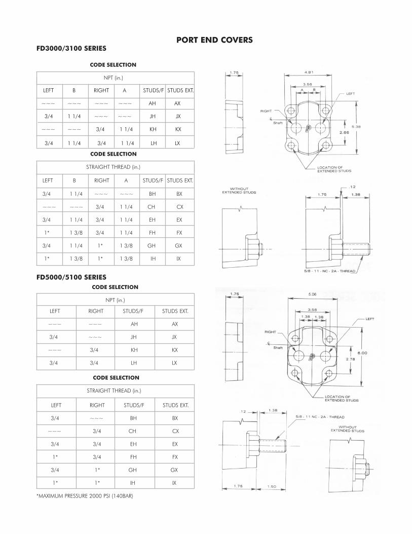
LEFT B RIGHT A STUDS/F STUDS EXT.
~~~ ~~~ ~~~ ~~~ AH AX
3/4 1 1/4 ~~~ ~~~ JH JX
~~~ ~~~ 3/4 1 1/4 KH KX
3/4 1 1/4 3/4 1 1/4 LH LX
CODE SELECTION
NPT (in.)
PORT END COVERSFD3000/3100 SERIES
CODE SELECTION
STRAIGHT THREAD (in.)
LEFT B RIGHT A STUDS/F STUDS EXT.
3/4 1 1/4 ~~~ ~~~ BH BX
~~~ ~~~ 3/4 1 1/4 CH CX
3/4 1 1/4 3/4 1 1/4 EH EX
1* 1 3/8 3/4 1 1/4 FH FX
3/4 1 1/4 1* 1 3/8 GH GX
1* 1 3/8 1* 1 3/8 IH IX
LEFT RIGHT STUDS/F STUDS EXT.
~~~ ~~~ AH AX
3/4 ~~~ JH JX
~~~ 3/4 KH KX
3/4 3/4 LH LX
CODE SELECTION
NPT (in.)
CODE SELECTION
STRAIGHT THREAD (in.)
LEFT RIGHT STUDS/F STUDS EXT.
3/4 ~~~ BH BX
~~~ 3/4 CH CX
3/4 3/4 EH EX
1* 3/4 FH FX
3/4 1* GH GX
1* 1* IH IX
*MAXIMUM PRESSURE 2000 PSI (140BAR)
FD5000/5100 SERIES

CODE SELECTION
NPT (in.)
PORT END COVERS
FD7000/7600 SERIES
CODE SELECTION
STRAIGHT THREAD (in.)
LEFT RIGHT STUDS/F STUDS EXT.
~~~ ~~~ AH AX
3/4 ~~~ JH JX
~~~ 3/4 KH KX
3/4 3/4 LH LX
LEFT RIGHT STUDS/F STUDS EXT.
3/4 ~~~ BH BX
~~~ 3/4 CH CX
3/4 3/4 EH EX
1 3/4 FH FX
3/4 1 GH GX
1 1 IH IX

GEAR HOUSINGS
FD3000/3100
CODE SELECTION GEAR WIDTH (in.)
N.P.T. DIAMETER (in.)
LEFT RIGHT 1/2 3/4 1 1 1/4 1 1/2 1 3/4 2
NONE NONE ZA05 ZA07 ZA10 ZA12 ZA15 ZA17 ZA20
NONE 3/4 HC10 HC12 HC15 HC17 HC20
NONE 1 XC12 XC15 XC17 XC20
1 3/4 HI12 HI15 HI17
1 1/4 1 XI17 XI20
CODE SELECTION GEAR WIDTH (in.)
4-BOLT FLANGE DIAMETER (in.)
LEFT RIGHT 1/2 3/4 1 1 1/4 1 1/2 1 3/4 2
NONE NONE ZA05 ZA07 ZA10 ZA12 ZA15 ZA17 ZA20
NONE 3/4 TC10 TC12 TC15 TC17 TC20
NONE 1 NC12 NC15 NC17 NC20
1 3/4 TI12 TI15 TI17
1 1/4 1 NI15 NI17 NI20
CODE SELECTION GEAR WIDTH (in.)
STRAIGHT THREAD DIAMETER (in.)
LEFT RIGHT 1/2 3/4 1 1 1/4 1 1/2 1 3/4 2
NONE NONE ZA05 ZA07 ZA10 ZA12 ZA15 ZA17 ZA20
NONE 3/4 DC10 DC12 DC15 DC17 DC20
NONE 1 ZC15 ZC17 ZC20
1* 3/4 DI12* DI15 DI17
1 1/4* 1 ZI17* ZI20
* MAXIMUM PRESSURE 2000 PSI (140 BAR)
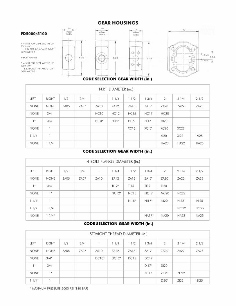
GEAR HOUSINGS
FD5000/5100
CODE SELECTION GEAR WIDTH (in.)
N.P.T. DIAMETER (in.)
LEFT RIGHT 1/2 3/4 1 1 1/4 1 1/2 1 3/4 2 2 1/4 2 1/2
NONE NONE ZA05 ZA07 ZA10 ZA12 ZA15 ZA17 ZA20 ZA22 ZA25
NONE 3/4 HC10 HC12 HC15 HC17 HC20
1* 3/4 HI10* HI12* HI15 HI17 HI20
NONE 1 XC15 XC17 XC20 XC22
1 1/4 1 XI20 XI22 XI25
NONE 1 1/4 HA20 HA22 HA25
CODE SELECTION GEAR WIDTH (in.)
4-BOLT FLANGE DIAMETER (in.)
LEFT RIGHT 1/2 3/4 1 1 1/4 1 1/2 1 3/4 2 2 1/4 2 1/2
NONE NONE ZA05 ZA07 ZA10 ZA12 ZA15 ZA17 ZA20 ZA22 ZA25
1* 3/4 TI12* TI15 TI17 TI20
NONE 1* NC12* NC15 NC17 NC20 NC22
1 1/4* 1 NI15* NI17* NI20 NI22 NI25
1 1/2 1 1/4 NO22 NO25
NONE 1 1/4* NA17* NA20 NA22 NA25
CODE SELECTION GEAR WIDTH (in.)
STRAIGHT THREAD DIAMETER (in.)
LEFT RIGHT 1/2 3/4 1 1 1/4 1 1/2 1 3/4 2 2 1/4 2 1/2
NONE NONE ZA05 ZA07 ZA10 ZA12 ZA15 ZA17 ZA20 ZA22 ZA25
NONE 3/4* DC10* DC12* DC15 DC17
1* 3/4 DI17* DI20
NONE 1* ZC17 ZC20 ZC22
1 1/4* 1 ZI20* ZI22 ZI25
* MAXIMUM PRESSURE 2000 PSI (140 BAR)
A = 5.61 FOR GEAR WIDTHS UPTO 2-1/4” 6.94 FOR 2-1/4” AND 2-1/2”GEAR WIDTHS
4-BOLT FLANGE
A = 5.31 FOR GEAR WIDTHS UPTO 2-1/4” 6.62 FOR 2-1/4” AND 2-1/2”GEAR WIDTHS

GEAR HOUSINGS
FD7500/7600
CODE SELECTION GEAR WIDTH (in.)
4-BOLT FLANGE DIAMETER (in.)
LEFT RIGHT 3/4 1 1 1/4 1 1/2 1 3/4 2 2 1/4 2 1/2 2 3/4 3
NONE NONE ZA07 ZA10 ZA12 ZA15 ZA17 ZA20 ZA22 ZA25 ZA27 ZA30
1 3/4 TI07 TI10
1 1 NE10 NE12 NE15 NE17 NE20
1 1/4* 1 NI10 NI12
1 1/4 1 1/4 NK12 NK15 NK17 NK20 NK22 NK25 NK27 NK30
1 1 1/2* NG12 NG15
1 1/2* 1 1/4 NO12 NO15 NO17 NO20
1 1/2 1 1/2 NQ17 NQ20 NQ22 NQ25 NQ27 NQ30
1 1/4 2* NM17 NM20 NM22 NM25 NM27 NM30
2* 1 1/2 NU17 NU20 NU22 NU25 NU27 NU30
2* 2* NW25 NW27 NW30
1 1/2 2 1/2* NS25 NS27 NS30
NONE 1 1/2 NT17 NT20 NT22
CODE SELECTION GEAR WIDTH (in.)
STRAIGHT THREAD DIAMETER (in.)
LEFT RIGHT 3/4 1 1 1/4 1 1/2 1 3/4 2 2 1/4 2 1/2 2 3/4 3
NONE NONE ZA07 ZA10 ZA12 ZA15 ZA17 ZA20 ZA22 ZA25 ZA27 ZA30
3/4 1 DF07
1 3/4 DI07
1 1 ZE10 ZE12 ZE15 ZE17 ZE20
1 1/4 1 1/4 ZK17
* MAXIMUM PRESSURE 2000 PSI (140 BAR)
STRAIGHT THREAD PORTS (JIC)PIPE PORTS (NPT) OR NO PORTS
A = 7.62 FOR GEAR WIDTHS 3/4” TO 1-1/2” 7.81 FOR GEAR WIDTHS 1-3/4” TO 3”
4-BOLT FLANGE PORTS
A = 7.50 FOR GEAR WIDTHS 3/4” TO 1-1/2” 7.56 FOR GEAR WIDTHS 1-3/4” TO 3”

AASECTION
BACK
FRONT
A-A
PORT SIZELEFT RIGHT
SPLITFLANGE
PIPETHREAD
STRAIGHTTHREAD
NONE
NONE NONENONENONENONE
3/4 1
3/4 1
3/43/43/4 1 1
3/43/43/4 1 1 3/4 3/4
NONE
NONE 3/4 11-1/41-1/2
NONENONE
NONENONE
11-1/41-1/21-1/41-1/2
11-1/41-1/21-1/41-1/2 1 1
A
D PLMO
AWJY
BUMJ
FWGWQWKYSY
FULUMUSJYJ UF VF
A
D QEFG
FIAJ
IGOB
GILIQIOJQJ
OGQGVGPBUB LB RB
A
D RIJK
FQLS
ECIF
GQOQPQMSQS
FCLCOCOFQF VK YK
BEARING CARRIER CODES
FD3000,FD5000,FD7500
Copyright © 2006 Permco © Bulletin # 06-FD1A