THIRD EDITION, 2002 - Insulation Institute · FIBROUS GLASS RESIDENTIAL DUCT CONSTRUCTION STANDARD...
100
FIBROUS GLASS RESIDENTIAL DUCT CONSTRUCTION STANDARDS NAIMA COPYRIGHT c 2002, NAIMA, ALL RIGHTS RESERVED $10.00 FABRICATION AND INSTALLATION TECHNIQUES FOR THE RESIDENTIAL HVAC DUCT CONTRACTOR FIBROUS GLASS RESIDENTIAL DUCT CONSTRUCTION STANDARD THIRD EDITION, 2002
Transcript of THIRD EDITION, 2002 - Insulation Institute · FIBROUS GLASS RESIDENTIAL DUCT CONSTRUCTION STANDARD...

FIB
RO
US
GL
AS
S R
ES
IDE
NT
IAL
DU
CT
CO
NS
TR
UC
TIO
N S
TAN
DA
RD
S�����
COPYRIGHT c 2002, NAIMA, ALL RIGHTS RESERVED $10.00
FABRICATIONAND INSTALLATION
TECHNIQUES FOR THERESIDENTIAL HVAC
DUCT CONTRACTOR
FIBROUS GLASSRESIDENTIAL DUCT
CONSTRUCTIONSTANDARDTHIRD EDITION, 2002

FIBROUS GLASS RESIDENTIAL DUCT CONSTRUCTION STANDARD
FIBROUS GLASSRESIDENTIAL DUCT
CONSTRUCTIONSTANDARD
LOW VELOCITY SYSTEMS1/2" w.g. (125 Pa) Maximum Static Pressure
THIRD EDITION, 2002

FIBROUS GLASS RESIDENTIAL DUCT CONSTRUCTION STANDARD
i
PREFACE
The North American Insulation Manufacturers Association(NAIMA) presents this Standard as a recommended method offabricating and installing air transmission ducts in residentialbuildings using fibrous glass material as specified herein.
Rectangular residential ducts covered by this Standardare designed to operate at 1/2" w.g. (125 Pa) static pressureor less. Maximum unreinforced duct size covered by thisStandard is 36” (900mm) for 475 and 800 EI board and42” (1050mm) for 1400 EI board. For fabrication ofrectangular ducts of larger sizes or for operation atgreater static pressures, refer to NAIMA PublicationAH116, Fibrous Glass Duct Construction Standard.Applicable portions of that Standard have been adaptedfor use by the residential fibrous glass duct contractor.
Fibrous glass duct products are designed for use incomfort heating and cooling systems operating atinternal air temperatures not less than 40oF (4oC) andnot greater than 250oF (121oC).
While fibrous glass duct board is rated at 2,400 feet perminute (12 m/sec) air velocity or greater, residential ductsystems typically operate at velocities of 1,200 feet perminute (6 m/sec) or less.
Flexible duct installation techniques covered by thisStandard are designed to complement rectangular,ten-sided, or round fibrous glass duct systems. Morecomprehensive information on the subject of flexibleducts may be found in the current edition of the AirDiffusion Council (ADC) publication, Flexible DuctPerformance and Installation Standards.
Overall HVAC duct system design issues are beyond thescope of this Standard. However, if satisfactory duct systemperformance is to be achieved, it is important for the systemdesigner to calculate HVAC loads on a room-by-room basisand to size ducts accordingly. It is recommended thatindustry information, such as Air Conditioning ContractorsAssociation (ACCA) Manuals D (duct sizing) and J (loadcalculation), be consulted for guidance in these critical areas.
Underwriters Laboratories Inc. Standard for Closure Systemsfor Use With Rigid Air Ducts and Air Connectors, UL 181A,incorporates key provisions of the UL 181 Standard, as well asadditional provisions developed by NAIMA and various closurematerial manufacturers. The resultant standard provides themeans for assuring the contractor and building owner thatthe selected closure system will, when properly applied,perform within varied environmental conditions.
This Standard was developed using reliable engineeringprinciples and research, plus consultation with andinformation obtained from manufacturers, contractors, testinglaboratories, and others having specialized experience.They are subject to revision as further experience andinvestigation may show is necessary or desirable.Construction and products which comply with thisStandard will not necessarily be acceptable if, whenexamined and tested, they are found to have otherfeatures which impair the result contemplated by theserequirements. The North American InsulationManufacturers Association assumes no responsibilityand accepts no liability for the application of the principlesor techniques contained in this Standard.
In particular, NAIMA makes no warranty of any kind,express or implied, regarding merchantabilityor fitness for any particular purpose, inconnection with the information supplied herein.
Authorities considering adoption of this Standard shouldreview all Federal, state, local and contractual regulationsapplicable to specific installations.
This Standard is not intended to preclude alternate methodsand materials of fabrication, closure, reinforcement andsupport, when such methods and materials can bedocumented as providing equivalent performance.
The North American Insulation Manufacturers Associationextends its thanks to the member companies of its AirHandling Technical Subcommittee who have contributedtheir time and talents in the development of this Standard.
NAIMA Air Handling Member Companies:
CertainTeed Corporation 800-233-8990P.O. Box 860Valley Forge, PA 19482
Johns Manville Corp. 800-654-3103P.O. Box 5108Denver, CO 80217
Knauf Fiber Glass 800-825-4434One Knauf DriveShelbyville, IN 46176
Owens Corning 800-GET-PINKOne Owens Corning ParkwayToledo, OH 43659

FIBROUS GLASS RESIDENTIAL DUCT CONSTRUCTION STANDARD
ii
CONTENTS
Preface .................................................................................................................................................................................... iContents ............................................................................................................................................................................ ii, iii
SECTION I. PERFORMANCE CRITERIAPerformance characteristics, fibrous glass duct board .............................................................................................. 1-2, 1-3Characteristics and limitations for residential systems ...................................................................................................... 1-4Performance characteristics, flexible duct ........................................................................................................................ 1-4Installation check list .......................................................................................................................................................... 1-6
SECTION II. GENERAL SYSTEM FABRICATIONIntroduction to basic residential duct system types .......................................................................................................... 2-2Extended plenum system - Description ............................................................................................................................. 2-3Radial system - Description ............................................................................................................................................... 2-4Return systems .................................................................................................................................................................. 2-5Fabrication logistics ........................................................................................................................................................... 2-6Principles of modular duct construction ............................................................................................................................ 2-7Layout and hand fabrication methods ............................................................................................................................... 2-8Hand grooving tools ........................................................................................................................................................... 2-9Hand fabrication - Centerline method ..................................................................................................................... 2-10, 2-11Hand fabrication - Guide edge method .................................................................................................................. 2-12, 2-13Machine fabrication - Straight duct modules ................................................................................................................... 2-14Machine grooving tools .................................................................................................................................................... 2-15Fabrication dimensions, one piece duct .......................................................................................................................... 2-16Fabrication dimensions, two piece U-style duct .............................................................................................................. 2-17Fabrication dimensions, two piece L-style duct .............................................................................................................. 2-18Fabrication dimensions, four piece duct ......................................................................................................................... 2-19Stretch-out dimensions, 1" (25mm) duct board ............................................................................................................... 2-20Board Utilization, 1” (25mm) duct board ......................................................................................................................... 2-21Stretch-out dimensions, 11/2” (38mm) duct board ............................................................................................................ 2-22Board utilization, 11/2” (38mm) duct board ....................................................................................................................... 2-23Stretch-out dimensions, 2” (51mm) duct board ............................................................................................................... 2-24Board utilization, 2” (51mm) duct board .......................................................................................................................... 2-25Fabrication of duct module .............................................................................................................................................. 2-26Joining two duct modules ................................................................................................................................................ 2-27Preformed round fibrous glass duct ...................................................................................................................... 2-28 - 2-30Ten-sided fibrous glass duct .................................................................................................................................. 2-31 - 2-34
SECTION III. EXTENDED PLENUM SYSTEM FABRICATIONSystem description ............................................................................................................................................................ 3-2Sheet metal and equipment connections .......................................................................................................................... 3-390o elbow with rail mounted turning vanes from module ................................................................................................... 3-490o elbow with turning vanes from flat grooved duct board .............................................................................................. 3-5Three piece 90o elbow from duct board module ................................................................................................................ 3-6Elbows of less than 90o from duct board module .............................................................................................................. 3-7Tee from duct board module with rail mounted metal turning vanes ................................................................................. 3-8Tee from flat duct board with fibrous glass turning vanes ................................................................................................. 3-9One way 30o offset from duct board module ................................................................................................................... 3-10One way offset of any angle from duct board module ..................................................................................................... 3-11One way transition from duct board module, reducing square edge panel .................................................................... 3-12One way transition from duct board module, reducing shiplap panel ............................................................................. 3-13One way transition from duct board module, reducing both square edge and shiplap panels ...................................... 3-14One way transition from flat duct board, reducing shiplap edge panel .......................................................................... 3-15Focal (centerline) transitions ............................................................................................................................................ 3-16

FIBROUS GLASS RESIDENTIAL DUCT CONSTRUCTION STANDARD
iii
Transitions changing height and width from one piece of flat duct board ........................................................................ 3-17Transitions changing height and width from four pieces of flat duct board ...................................................................... 3-18Square and round taps ..................................................................................................................................................... 3-19Wide mouth tap ................................................................................................................................................................. 3-20End caps ........................................................................................................................................................................... 3-21Dampers and other Accessories - Mounting .................................................................................................................... 3-22Installing taps to grilles and diffusers ............................................................................................................................... 3-23
SECTION IV. RADIAL SYSTEM FABRICATIONSystem description ............................................................................................................................................................. 4-2Fibrous glass duct board plenum ....................................................................................................................................... 4-3Triangular distribution box from 1" (25mm) duct board ....................................................................................................... 4-4Rectangular distribution box from 1" (25mm) duct board ................................................................................................... 4-5Flexible duct connection - Closure strap method ............................................................................................................... 4-6Flexible duct connection - Insulated collar method ............................................................................................................ 4-7
SECTION V. CLOSURE General - UL 181A listed closure methods .................................................................................. 5-2Closure - UL 181A, Part I (P) - Pressure sensitive aluminum foil tape ................................................................................ 5-3Closure - UL 181A, Part II (H) - Heat activated tape ........................................................................................................... 5-4Closure - UL 181A, Part III (M) - Glass fabric and mastic ................................................................................................... 5-5
SECTION VI. HANGERS AND SUPPORTSSuspending and supporting fibrous glass duct systems ................................................................................................... 6-2Suspending and supporting flexible ductwork ................................................................................................................... 6-3Suspending and supporting pre-formed round and ten-sided fibrous glass duct ............................................................. 6-4
SECTION VII. DAMAGE REPAIRRepair of small facing or closure tears ............................................................................................................................... 7-2Repair of major damage to one panel ................................................................................................................................ 7-3Replacing entire shiplap panel ........................................................................................................................................... 7-4Replacing entire square edge panel .................................................................................................................................. 7-5
APPENDIXReferences .................................................................................................................................................................. A-1, A-2Guide Specifications ....................................................................................................................................................A-3-A-5ASHRAE/IES 90.1 - 2001 Minimum Duct Insulation ........................................................................................................... A-6ASHRAE 90.2 - 2001 Minimum Duct Insulation ................................................................................................................. A-7The facts on fiber glass............................................................................................................................................... A-8, A-9
A NOTE ABOUT THE USE OF METRIC (SI) UNITS IN THIS STANDARD
Two forms of conversion are used in this document:
1. Critical fabrication dimensions, where accuracy is essential for correct fabrication, are converted fromU.S. (IP) units (inches) to the nearest whole millimeter. Example: 2" = 102mm.
2. Where accuracy is not critical, or where dimensions are given as approximate, nominal, orminimum/maximum, inches are rounded to the nearest convenient SI value. Example: 2" = 100mm.


FIBROUS GLASS RESIDENTIAL DUCT CONSTRUCTION STANDARD
SECTION I
PERFORMANCECRITERIA
1-1

FIBROUS GLASS RESIDENTIAL DUCT CONSTRUCTION STANDARD
1-2
SECTION I - PERFORMANCE CRITERIA
General requirements of air ducts
A duct system is a structural assembly whose primaryfunction is to convey air between specific points. Infulfilling this function, the duct assembly must performsatisfactorily with respect to certain fundamentalperformance characteristics. Elements of the assemblyare duct material, seams and joint treatments. Withregard to the duct assembly and its elements, theoreticaland/or practical limits must be established for:
1. Dimensional stability, deformation and deflection.2. Containment of the air being conveyed.3. Exposure to damage, weather, temperature
extremes, flexure cycles or other in-service conditions.4. Support.
Analysis and determination of requirements forfibrous glass ducts
Fibrous glass duct systems designed for use in residentialsituations are fabricated from three types of product:1. Boards of resin bonded inorganic glass fibers 1”, 11/2”, or2” (25mm, 38mm, or 51mm) thick, having a factory-appliedreinforced aluminum foil/kraft laminate exterior air barrierfinish, for fabricating rectangular and ten-sided ducts,plenums and distribution boxes.2. Lengths of preformed rigid tubular fibrous glass ductof various diameters, with a reinforced aluminum exteriorfinish.3. Lengths of round flexible duct, having a reinforcedinner air barrier core, resilient fibrous glass insulation,and an outer vapor retarder jacket, cut to requiredlengths for ducts or run-outs from fibrous glass trunkducts or plenums to grilles and diffusers.
General requirements for air ducts are as follows,except where differing procedures are part of amanufacturer’s UL 181 listing and must be usedin lieu of the procedures shown in this manual.
1. DUCT BOARD
1.1. Strength and Deflection
Board stiffness is defined by flexural rigidity, which is theproduct of Young’s Modulus of Elasticity (E) and themoment of inertia (I) per unit width. Boards are identifiedby ratings of 475-EI, 800-EI, and 1400-EI, respectively.
Flexural rigidity rating is determined in accordance withNAIMA Test Number AHS-100-74 and is an average ofspecimens taken from a sheet of the duct board.
Duct board deflection relative to a flat position of theboard is limited to one one-hundredth (1/100) of the span.This criterion is based on stress in the material notexceeding the proportional elastic limit of the materialwith suitable safety margins built in.
1.2. Fatigue Tests
In normal service conditions, ducts incur pressurecycles. In investigating the potential effects of fatigueoccurring in a duct system, sections of each duct boardtype (475-EI and 800-EI) were cycled from atmosphericpressure to 150% of design pressure. Each test assemblyconsisted of not less than three 48" (1200mm) (nominal)long sections of fibrous glass duct. The tests wereconducted at 3 to 4 cycles per minute for 50,000 cycles,after which samples were removed from the center ofthe duct and the board’s flexural rigidity (EI) determinedin accordance with NAIMA AHS-100-74. For comparisonof board strengths and deterioration, comparablesamples of new duct board of each class were tested inaccordance with the same NAIMA test method. In eachcase there was no significant reduction in the flexuralrigidity of the cycled boards.
1.3. UL 181 Class 1 Air Duct Rating
When ducts must conform to NFPA Standards 90A/90Band/or model codes, fibrous glass ducts are required toconform to the following requirements:
1. They shall be constructed of Class 1 duct materialsas tested in accordance with Underwriters LaboratoriesStandard for Factory-Made Air Ducts and Air Connectors,UL 181.
2. Such ducts shall be installed in accordance withthe conditions of their listing.
3. They may not be used in air duct systems whichoperate with an air temperature higher than 250°F (121°C)entering the ducts.
4. They shall not be used as vertical risers in air ductsystems serving more than two stories.
Under UL Standard 181 Class I air duct materials have aflame spread rating of 25 and a smoke developed rating

FIBROUS GLASS RESIDENTIAL DUCT CONSTRUCTION STANDARD
1-3
of 50. The following portions of UL 181 are applicable torigid fibrous glass ducts:
Surface burning characteristicsFlame penetrationBurningCorrosion (metal parts not inherently corrosion resistant)Mold growth and humidityTemperaturePunctureStatic loadImpactErosion*Pressure*Collapse*Leakage
*Erosion, pressure, and collapse tests are run at 21/2times manufacturers’ stated ratings. For the erosion test,the variable is velocity. For the pressure test, the variableis positive pressure. For the collapse test, the variable isnegative pressure.
1.4. Longitudinal Seams, Transverse Joints
Recommended methods of forming and aligning ductsides are given in detail in this manual. In order to maintainalignment of the duct assembly, both longitudinal seamsand transverse joints are sealed with a continuous closuresystem. Field observations and laboratory testing haveindicated very low leakage rates.
Closures are an integral part of fibrous glass duct construction.Only those closures complying with UL 181A, Part I (P)for pressure sensitive aluminum foil tape, Part II (H) forheat activated aluminum foil tape, or Part III (M) for glassfabric and mastic, have been tested for compliance withall structural and safety requirements. See Section V of thisStandard for detailed closure application information.
1.5. Duct Support
Hanger sizing and spacing for fibrous glass duct boardsystems are coordinated with other performancerequirements of duct components. Hangers andsupports must be placed for proper support of all ductboard fittings and accessories so that taped joints arenot placed under additional unanticipated stress.See Section VI of this Standard. For further information,Section VI, NAIMA Fibrous Glass Duct ConstructionStandard, should be consulted.
1.6. Themal Performance
At 75°F (24°C) mean temperature, fibrous glass ductboard provides the following thermal performance values:
1" (25mm) 11/2" (38mm) 2” (51mm)R value, hr•ft2•°F/Btu (RSI, m2•°C/W) 4.3 (0.76) 6.5 (1.14) 8.7 (1.53)k value, Btu•in/hr•ft2•°F (W/m•°C) 0.23 (0.033) 0.23 (0.033) 0.23 (0.033)C value, Btu/hr•ft2•°F (W/m2•°C) 0.23 (1.32) 0.16 (0.88) 0.12 (0.65)
Consult local codes for specific thermal requirements.Where codes do not address thermal value, NAIMArecommends using current ASHRAE minimum ductinsulation requirements. See Appendix, Pages A-6, A-7.
1.7. Acoustical Performance
Fibrous glass duct board absorbs fan and air turbulencenoise and reduces the popping noises caused byexpansion and contraction. Typical acoustical performanceof fibrous glass duct board, measured in accordancewith ASTM C 423 (mounting A), is as follows:
SOUND ABSORPTION COEFFICIENTS AT OCTAVE BAND CENTER FREQUENCIES, Hz
125 250 500 1000 2000 4000 NRC1.0" (25mm) .03 .18 .61 .83 .89 .93 .651.5" (38mm) .09 .33 .89 .96 .95 .94 .802.0” (51mm) .17 .68 1.08 1.05 1.04 1.06 .95
A major benefit of the fibrous glass duct system is itscontribution to a quiet indoor environment. However,acoustical performance is an extremely complex subject;manufacturers of the products involved should beconsulted for further information.
1.8. Leakage
Ducts should be sufficiently airtight to ensure quiet, economicalperformance. Supply duct leakage reduces the deliveredvolumes of air at diffusers and registers, which must becompensated for by increasing the total quantity of supplyair. Return duct leakage reduces system thermal efficiencyand may draw unwanted air and contaminants into the system.
Duct systems covered in this Standard have inherentlylow leakage. For details on tests which have beenconducted, refer to NAIMA Fibrous Glass DuctConstruction Standard, current edition.

FIBROUS GLASS RESIDENTIAL DUCT CONSTRUCTION STANDARD
1-4
2. RIGID FIBROUS GLASS DUCT CHARACTERISTICSAND LIMITATIONS FOR RESIDENTIAL SYSTEMS
2.1. Flexural Rigidity (EI)
Average in the board, not less than rating of 475, 800 or1400 pounds-inches2 per inch of width when tested inaccordance with NAIMA Test Method AHS-100-74.
2.2. Maximum Static Pressure in Duct
1/2” w.g. (125 Pa), positive or negative, maximum duct span36” (900mm) for 475 and 800 EI board and 42” (1050mm)for 1400 EI board. For ducts of greater span, or for ductsystems operating at higher pressures, see NAIMAFibrous Glass Duct Construction Standard.
2.3. Maximum Air Velocity in Duct
Rated at 2,400 feet per minute (12 m/sec) or greater.Refer to manufacturers’ published data.
2.4. Maximum Allowable Deflection
One one-hundredth of duct span.
2.5. Board Fatigue
No significant deformation or deficiency of duct sectionsafter 50,000 cycles at 3 to 4 cycles per minute from zeroto 11/2 times operating pressure.
2.6. Water Vapor Sorption
Water vapor sorption of the duct board shall not exceed 5%by weight under conditions of 120oF (49oC) dry bulb at 95%relative humidity for 96 hours duration when tested inaccordance with ASTM C 1104.
2.7. Temperature
40oF (4oC) minimum inside duct.250°F (121°C) maximum inside duct.150°F (66°C) maximum duct surface temperature
2.8. Corrosiveness
Non-corrosive in contact with galvanized steel, copper, oraluminum when compared to control specimen in contact with
clean sterile cotton when tested in accordance with ASTM C 665.
2.9. Closure
Closure materials (pressure sensitive tapes, heat activatedtapes, glass fabric and mastic) shall conform to UnderwritersLaboratories Standard UL 181A. When installed inaccordance with manufacturers' instructions, closure systemswill conform to UL 181 Class 1 Air Duct requirements.
2.10. Safety standards
National Fire Protection Association Standards 90A/90B.
2.11. Bacteria and fungi resistance
Fibrous glass duct products meet fungal and bacterialgrowth requirements when subjected to microbial attackas described in ASTM C 1338 and standard practicesASTM G 21-96 (fungus test) and ASTM G 22-95(bacteria test). UL 181 also includes a mold growth test.
2.12. Restrictions
Fibrous glass duct systems should not be used in thefollowing applications:
• Kitchen or fume exhaust ducts, or to convey solidsor corrosive gases.
• Installation in concrete or buried below grade.• Outdoors.• As casings and/or housings of built-up equipment.• Immediately adjacent to high temperature electric
heating coils without radiation protection. Refer to NAIMAFibrous Glass Duct Construction Standard for properdesign.
• For vertical risers in air duct systems serving morethan two stories.
• With equipment of any type which does not includeautomatic maximum temperature controls.
• With coal or wood fueled equipment• As penetrations in construction where fire dampers are
required, except as shown in NAIMA Fibrous Glass DuctConstruction Standard with the fire damper installedin a sheet metal sleeve extending through the wall.
2.13. Mounting of accessories
When mounting equipment, dampers, damper operators,control motors, etc., the duct system shall be adequately

FIBROUS GLASS RESIDENTIAL DUCT CONSTRUCTION STANDARD
1-5
reinforced and supported to accomodate the additionalweight of the equipment without damage to the ductmaterial. Particularly important is mounting both dampersand operators on the same sleeve or mounting plate.
2.14. Moisture control
The following precautions should be taken to avoidexposure of duct board to liquid water:
• When using either evaporative coolers or humidifiers,the immediate area around the device introducingwater into the system should be protected by usinga drip pan and protective sheet metal sleeve.
• Duct systems running through non-conditionedspace and used for cooling only must be tightlyclosed during the heating season to preventaccumulation of water vapor in the duct system.
• Fibrous glass duct materials that have become wetat the job-site before or during installation shouldnot be installed. Duct systems which, in service,are found to be wet should be replaced. Consultthe product manufacturer for further information.
3. FLEXIBLE DUCT
3.1. UL 181 Testing Program
Flexible duct referred to in this Standard is tested inaccordance with Underwriters Laboratories Standard forFactory-Made Air Ducts and Air Connectors, UL 181.The test program for flexible duct includes the following:
Surface burning characteristics (UL 723) Class 1 materialFlame spread 25 or lessSmoke developed 50 or less
Flame penetration ImpactBurning LeakageCorrosion (metal parts not Erosion*
inherently corrosion resistant) Pressure*Mold growth and humidity Collapse*Temperature TensionPuncture TorsionStatic load Bending
*Erosion, pressure, and collapse tests are run at 21/2 times manufacturers’ statedratings. For the erosion test, the variable is velocity. For the pressure test the variableis positive pressure. For the collapse test, the variable is negative pressure.
3.2. ADC Testing Program
Other properties of flexible air duct are tested in accordance
with test standards set by the Air Diffusion Council. Theseinclude thermal performance, friction loss, acousticalperformance, static pressure / temperature performance,and leakage.
3.3. Connections with Flexible Duct
Recommended methods of connecting flexible duct tofibrous glass duct board are shown in Section IV of thisStandard. If other methods are used, proponents of suchmethods are responsible for demonstrating equivalency.
Recommended methods of connecting flexible duct todiffusers, registers and grilles are available from the AirDiffusion Council.
For further information or for detailed design data, referto the current edition of Air Diffusion Council’s FlexibleAir Duct Performance & Installation Standards.
4. Compliance with Building Codes
Fibrous glass insulated duct systems meet the followingmodel codes and most other applicable codes:
ICC - International Code Council, Inc.• International Mechanical Code• International Building Code• International Residential Code• International Energy Conservation Code
Note: This code is replacing BOCA, CABO, ICBO,and SBCCI codes, although some juristictionsmay continue to reference some of them.
BOCA - Building Officials and Code AdministratorsInternational
• National Building Code• National Mechanical Code: (see ICC above)
CABO - Council of American Building Officials• One and Two Family Dwelling Code• CABO Model Energy Code
ICBO - International Conference of Building Officials• Uniform Building Code• Uniform Mechanical Code
SBCCI - Southern Building Code Congress International• Standard Building Code• Standard Mechanical Code
See Appendix for current code edition and how tocontact code organizations.

FIBROUS GLASS RESIDENTIAL DUCT CONSTRUCTION STANDARD
1-6
FIBROUS GLASS RESIDENTIAL DUCT SYSTEM INSTALLATION CHECK LISTAll answers should be in the “YES OR NOT APPLICABLE” column. If a check mark appears in the “NO” column, bring it tothe attention of the HVAC Contractor.
Project name and numberHVAC contractor BuilderChecklist compiled by Date
A. Product YES/NA NO(Refer to manufacturer’s literature and current UL Instruction Sheet)
1. Is product used identified as duct board by facing imprint? ( ) ( )2. Is UL label present? (While each board has one UL label, not every duct section will be labeled.) ( ) ( )3. Are there NO visual signs of facing delamination (ballooning, condensation if system operating)? ( ) ( )
B. Fabrication and installation (See Sections II, III, IV)4. Are connections to unit or sheet metal ducts in accordance with NAIMA manual standards? ( ) ( )5. Are turning vanes, where required, installed in accordance with NAIMA manual standards? ( ) ( )6. Is correct hardware attaching metal parts to duct per NAIMA manual or submittal drawings? ( ) ( )7. Are round duct take-offs of a type designed for use with fibrous glass duct board? ( ) ( )8. If spin-in fittings are used, are both inner and outer rings secure against the duct board? ( ) ( )9. If dove-tail fittings are used, are all tabs bent outward 90o to secure the fitting to the duct board? ( ) ( )10. Are round duct take-off holes properly sized to fittings? ( ) ( )11. Are fibrous glass duct board distribution boxes fabricated per manufacturer’s instructions? ( ) ( )12. Are staples galvanized steel, and of the outward clinching type? ( ) ( )13. If staples are not used, are tape tabs, min. 1 per side and 12” (300mm) on centers, used instead? ( ) ( )14. Are NO panels in any fitting shorter than 6” (150mm), including male and female shiplap joints? ( ) ( )15. Do the joints and seams on distribution boxes have stapling flaps or tape tabs? ( ) ( )
C. Closure (See Section V)16. Are all joints and seams properly taped or closed with glass fabric and mastic? ( ) ( )17. Is the closure system listed under UL 181A, Parts I (P), II (H), or III (M)? ( ) ( )18. Are all pressure sensitive tape closures the proper width and rubbed down adequately, with staples or scrim
in facing clearly visible? ( ) ( )19. Are heat activated closures applied correctly, as shown by changing dot color? ( ) ( )20. Does tape show manufacturer name, UL 181A nomenclature, and date code? ( ) ( )
D. Hanging and Support (See Section VI)21. Are hangers installed in accordance with the hanger schedule published in the NAIMA manual? ( ) ( )22. Are hanger designs in accordance with those shown in the NAIMA manual? ( ) ( )23. Are accessories that add weight to the system separately supported so as not to stress the system? ( ) ( )24. If codes allow ducts to rest on ceiling joists, are they secured to prevent accidental movement? ( ) ( )25. In humid climates, is system suspended or elevated at least 1” (25mm) above ceiling insulation? ( ) ( )26. Are ducts in crawl spaces at least 1” (25mm) from floor insulation with at least 4” (100mm) ground clearance? ( ) ( )
E. General27. Is system operating within the design limitations for which it was built? ( ) ( )28. Have all tears or punctures of facing material been repaired per methods shown in the NAIMA manual? ( ) ( )29. Are all metal accessory items galvanized? ( ) ( )30. Are all runs of flexible duct installed in accordance with Air Diffusion Council Standards manual? ( ) ( )31. Are all flexible duct connections to fibrous glass duct board made as shown in ADC Standards Manual? ( ) ( )32. Are all runs of flexible duct as straight as possible and free from unnecessary loops or bends? ( ) ( )
NOTE: For fabrication, installation, hanging, and other details, refer to NAIMA Fibrous Glass Residential Duct ConstructionStandard and/or Air Diffusion Council Flexible Air Duct Performance & Installation Standards, current editions.

FIBROUS GLASS RESIDENTIAL DUCT CONSTRUCTION STANDARD
SECTION II
GENERALSYSTEM FABRICATION
2-1

FIBROUS GLASS RESIDENTIAL DUCT CONSTRUCTION STANDARD
2-2
INTRODUCTION TO BASIC SYSTEM TYPES
Features and Benefits Types of Systems
Air duct systems for residential installation generally fallinto either of two basic types, more fully described onthe following two pages:
1. Extended Plenum Supply Systems
A plenum is installed on the central fan unit. Singlefibrous glass ducts extend from this plenum towardperimeter walls, supplying run-outs to individual roomregisters or diffusers. Run-outs may be fabricated fromfibrous glass duct board, pre-formed round duct,ten-sided fibrous glass duct, insulated flexible duct,or insulated metal duct. See page 2-3. Depending onthe building layout, number of rooms, location of centralequipment, local climatic conditions, and other factors,a fibrous glass duct system of this type may be assimple or as complex as the situation requires.
The extended plenum system is preferred for largeresidential situations and is the ideal system forbasement installation. It combines sturdiness withhighly efficient acoustical and thermal performance.
2. Radial Supply Systems
A plenum is installed on the central fan unit. Singletrunks of flexible duct extend from this plenum torectangular or triangular distribution boxes fabricatedfrom fibrous glass duct board. From each distribution box,two or more flexible ducts run out to individual roomregisters or diffusers. See page 2-4. A simpler type ofradial system incorporates lengths of flexible duct, eachof which runs from the plenum directly to an individualroom register or diffuser.
These systems are typically used in unfinished attics.The system is less suited for basement locations.The radial system is harder to balance than theextended plenum system, and thermal and acousticalperformance are not as efficient. However, a carefullydesigned radial duct system with distribution boxes canbe a good compromise between the extended plenumsystem and a simple radial duct system.
Heating, ventilating and air conditioning duct systemsincorporating fibrous glass duct board provide levels ofthermal and acoustical efficiency and occupant comfortthat uninsulated, unsealed sheet metal systems may notdeliver. Fibrous glass duct board eliminates the needto wrap or line sheet metal with insulation to achieveacceptable thermal and acoustical performance.
Fibrous glass duct board and insulated flexible ductsystems provide assured thermal performance throughcontrolled insulation thickness. They absorb centralequipment and air turbulence noise, and reduce noisecaused by expansion, contraction and vibration.
These systems are UL181 listed and labeled. With theuse of UL181A or UL181B listed closure systems, theymeet model codes and are fully supported by bothmanufacturing and contracting industry standards.Light in weight, easy to transport and handle, fibrousglass air duct systems can be quickly and easily in-stalled with assurance of substantially airtight perfor-mance.
This Standard describes HVAC duct systems designedfor use in residential situations including but not limited to
• Single family residences of one or more stories;• Two, three, and four family apartment buildings of
one to three stories:• Condominium and cluster housing projects of one to
three stories.

FIBROUS GLASS RESIDENTIAL DUCT CONSTRUCTION STANDARD
2-3
EXTENDED PLENUM SYSTEM(See Section III for fabrication details)
Fibrous glass ducts extend from central equipmentsupplying run-outs to individual room registers.Run-outs may be fibrous glass duct, rigid round duct,ten-sided duct, insulated flexible duct, or insulatedmetal duct. Systems may either be simple(i.e., a straight run of duct of one size) or complex(including reducers, branches, offsets and otherfittings), depending on structural and room layout.
Extended plenum system components
A typical extended plenum system may be made up ofa variety of duct components. Typical ones are shown inFig. 2-1. Many others are detailed in Section III of this Standard.
1. Plenum2. Connection of plenum to central air equipment3. Standard fibrous glass duct module, used in straight
duct runs of one size to extend plenum, or as a basisfor fabricating fittings
4. Taps for square and round duct run-outs
Fig. 2-1. Extended plenum system
TEN-SIDED DUCTRUN-OUTS
PLENUMPLENUMPLENUMPLENUMPLENUMEXTENSIONEXTENSIONEXTENSIONEXTENSIONEXTENSION
STANDARDDUCT MODULE
REGISTERS
PREFORMED ROUNDDUCT RUN-OUTS
This illustration shows how different types of fibrous glassinsulated ducts can be utilized in typical residentialsituations. It is not meant to suggest that a single systemwould combine all of these types in the manner shown.
REGISTERS
FLEXIBLE DUCTRUN-OUTS
RECTANGULAR DUCTRUN-OUTS
CENTRAL AIR UNIT
10
98
5
12
2
4
6
43
1
4
11
7
PLENUM
5. Wide mouth tap6. Transition (reducer) - Several types are described in
Section III7. One-way offset (other configurations are described
in Section III)8. Three piece 90o elbow (other configurations are
described in Section III)9. Connections to registers10.End cap (three types are described in Section III)11.Tee with equal legs12.Hangers and supports

FIBROUS GLASS RESIDENTIAL DUCT CONSTRUCTION STANDARD
2-4
Load calculation and duct sizing are especially importantin the design of a radial system. In nearly all cases,various sizes of flexible duct will be needed to supplyadequate conditioned air to each room. Consult sourcessuch as ACCA Manual J (for guidance on room loadcalculation) and ACCA Manual D (duct sizing).(See references, Appendix, Page A-1.)
1. Plenum2. Connection of plenum to central air equipment3. Triangular distribution box4. Rectangular distribution box5. Flexible duct connections to fibrous glass units6. Flexible duct connections to registers7. Hangers and supports8. Flexible duct run-out to a single register
RADIAL SYSTEM(See Section IV for Fabrication Details)
In place of an extended plenum fabricated from fibrousglass duct board, flexible duct is used to supply air fromplenum to room registers. Flexible duct trunks extendfrom the plenum to triangular or rectangular distributionboxes fabricated from fibrous glass duct board. Individualroom registers and diffusers are supplied by flexible ductrun-outs from these distribution boxes.
In the simplest version of the radial system, fibrous glassduct board distribution boxes are eliminated and eachroom register or diffuser is supplied by a single flexibleduct running directly from the plenum.
Radial Duct System Components
Fig. 2-2 shows a radial system with fibrous glass ductboard distribution boxes supplied by three flexible ducttrunks coming from the plenum. The fourth flexible ductfrom the plenum supplies a single register, as would bethe case for all registers in the simplest version of theradial system.
REGISTERS
RUN-OUTS
TRIANGULARDISTRIBUTION BOX
CENTRAL AIR UNIT
RECTANGULAR DISTRIBUTION BOX
PLENUM
RUN-OUTS
REGISTERS
Fig. 2-2. Radial system with distribution boxes
4
3
7
2
1
68
5

FIBROUS GLASS RESIDENTIAL DUCT CONSTRUCTION STANDARD
2-5
RETURN SYSTEMSGeneral
Provisions must be made for the return of conditioned airfrom occupied spaces to central air equipment. Withoutadequate provisions for return air flow, the system maydeliver insufficient air to occupied spaces and may alsolose overall thermal efficiency. This is an especially criticalfactor in today’s tight, energy-efficient construction.
There are two basic approaches to providing for returnair: ducted and non-ducted. (Many systems arecombinations of these two approaches.)
Ducted return systems
Ducted return systems are preferable because ductsprovide the most thermally and acoustically efficient pathfor air to return to central units.
Ideally, every room or space should have a return airregister ducted into the return system. This makes itunnecessary to resort to such expedients as placinggrilles in doors, under-cutting doors so return air canflow under them, or (in worst cases) simply leavingdoors open and suffering the resulting lack of privacy.
Return ducts must be tightly sealed. If return air ductsleak, air and contaminants may be drawn into thesystem from undesirable sources such as hot or coldattics, crawl spaces, or garages.
ENCLOSE SPACE WITH DUCTBOARD AFTER CAULKING
FLOOR/JOISTJUNCTURE
AIR FLOWDIRECTION
SEAL EDGESTO PREVENT
AIR INFILTRATION
Fig. 2-3. Stud cavity used as path for return air. Fig. 2-4. Space between joists used as path for return air.
It is often important that return ducts be acousticallytreated to prevent central equipment noise from reachingoccupied spaces. Fibrous glass ducts, insulated flexibleducts, and sheet metal ducts with fibrous glass ductliners can all be used to provide acceptable noisecontrol. Duct wraps provide no acoustical benefits.
Thermal insulation is also important on return systemsbecause the temperature differential between the ambientair and the return air in the duct is often large.
Non-Ducted Return Systems
Stud cavities and spaces between floor joists are oftenused as return air paths. Unless these paths are tightlysealed, return air may be drawn into central air equipmentfrom unconditioned spaces such as hot or cold attics,crawl spaces and garages, and supplied to occupiedspaces. Such unwanted air can easily enter a non-ductedreturn system through numerous construction openings.
The figures below suggest two ways in which leakagecan be minimized when stud and joist cavities are usedas return ducts.
The Importance of Planning Ahead
The builder and the HVAC contractor should work togetherin the early stages of construction to ensure opportunitiesto provide for return air systems when it can still be doneright - before interior walls, ceilings, and other constructionblock access to potential locations for return air paths.
BLOCK OFF TO PREVENT AIR INFILTRATIONFROMATTIC

FIBROUS GLASS RESIDENTIAL DUCT CONSTRUCTION STANDARD
2-6
FABRICATION LOGISTICS
When planning fibrous glass duct system fabricationlogistics, the contractor has several choices concerningtools and workplace. Selection of the most suitablefabrication tools, and the best place to do the work, willdepend on such considerations as:• Type of system being installed: extended plenum,radial system with duct board distribution boxes, orsimple flexible duct radial system.• Type of project: whether large or small single familyresidence, a number of similar tract houses, a multi-familyor condominium project.• Availability of suitable clean, dry work space eitherat the duct fabricator’s shop or on the job-site.• Availability of trained, experienced workers.
Fabrication Tools
This Standard identifies and describes the use of bothhand tools and machines designed for fabrication offibrous glass duct board. (Fabrication of flexible ductis all done with hand tools.)• Hand tool fabrication of fibrous glass duct board:Specially designed tools are used to cut grooves andstapling flaps in fibrous glass duct board. See pages2-9 through 2-13. Straight duct modules are thenfabricated by folding, stapling, and sealing groovedboards as described on page 2-26.• Machine fabrication of fibrous glass duct board: Thesame grooves and stapling flaps are cut in fibrous glassduct board by powered groove-cutting machines. Seepages 2-14 and 2-15. Straight duct modules are thenfabricated as described on page 2-26.• Duct board fitting fabrication: Fittings such as elbows,tees, offsets and transitions are made using handgrooving tools either from straight duct modules or flatduct board. See Section III of this Standard.• System assembly: Straight duct modules, fittings andrectangular run-outs of fibrous glass duct board areconnected by stapling and sealing as shown on page 2-27.Joints and seams are sealed with pressure sensitive orheat activated aluminum foil tape or with glass fabricand mastic as shown in Section V of this Standard.• Flexible duct fabrication: Run-outs from trunk ducts ofplenum extensions to individual room registers and diffusersmay be made using insulated flexible duct cut to requiredlengths using a knife and a wire cutter. Connections offlexible duct to trunk ducts, plenum extensions, and registerboots are made in accordance with ADC Standard (SeeReferences, page A-1) and/or manufacturers’ instructions.
How and Where to Fabricate
Depending on the nature of the job, the contractor hasseveral options as to how and where to fabricate thefibrous glass duct system. Some of these are:• To fabricate all the straight duct modules and fittings inthe shop, using powered grooving and closure machines.This would be a good option if the project requires manyduct modules of the same size and/or many fittings of thesame design. Since fibrous glass duct elements are lightin weight and easy to handle, it may be practical to pre-assemble lengths of duct and truck these to the job-site.• To do all fabrication work at the job-site, includingmachine grooving. This might be the best option if the jobis a very large one and there is space to set up a job-siteshop with room for the machine plus storage space thatis clean, warm, and protected from the elements.• To do all fabrication at the job-site using hand grooving tools.• To groove the duct board on machines in the shop,shipping the flat grooved board to the job-site whereworkers can assemble straight modules, fabricatefittings, connect elements, and install the system. Atruck can haul much more of a fibrous glass ductsystem in one load when it’s in flat board form thanwhen it consists of fabricated modules and fittings.• If the system is of the radial type with fibrous glassduct board distribution boxes, the contractor can performnearly all of the fabrication work in the shop. Job-site workwill be limited to making connections between the plenumand the distribution boxes with the flexible duct, andconnecting the flexible duct to registers and diffusers.• If the system is of the simple radial type that does notinclude distribution boxes, essentially all of the fabricationwork will be done at the job-site since the work consistsmainly of connecting the flexible duct to the central unitplenum and to room registers and diffusers.
In any of the above cases, all duct system materials mustbe transported and stored so they are protected fromexposure to water, dirt, and physical damage. Job-site workareas must be clean, dry, and protected from the weather.
Pressure sensitive tape closures should not be attemptedat ambient temperatures below 50°F (10°C) unless heat isprovided as defined in Section V, CLOSURE. Consultmastic manufacturers regarding protection of materialduring storage, transportation and installation. Also readand follow instructions on product labels. For completeclosure details, refer to Section V of this Standard.

FIBROUS GLASS RESIDENTIAL DUCT CONSTRUCTION STANDARD
2-7
PRINCIPLES OF MODULAR DUCT CONSTRUCTION
In designing, fabricating and installing fibrous glass ductsystems, the principle of Modular Duct Construction(MDC) is used. This is based on use of the 48" (1220mm)(nominal)* duct module for both straight duct runs andfittings of most types.
The remaining pages of this section show how theseobjectives are met using the MDC principle.
Use of the MDC principle enhances productivity,minimizes the number of circumferential joints, simplifiesfabrication of fittings both in the shop and on the job,and improves the quality of workmanship.
*For actual installed length, subtract shiplap length fromnominal:
DUCT BOARD SHIPLAP INSTALLEDTHICKNESS LENGTH DUCT LENGTH
1" (25mm) 7/8" (22mm) 471/8” (1200mm)11/2" (38mm) 13/8" (35mm) 465/8” (1185mm)2” (51mm) 17/8” (48mm) 461/8” (1170mm)
Application of the MDC principle involves the followingdesign considerations:
• The modified shiplap groove is used in preference tothe V-groove method (see page 2-8).
• Elbows and tees are designed to be throatless.
• Transitions are extended to maintain themodule dimension.
• Sweep and radius fittings are not used.
• The male shiplap end of the duct section is alwaysinstalled facing the fan or equipment.
• Branch taps should be made from shiplap panelswherever possible.
• The integrity of the module should be maintained asconsistently as possible throughout the system duringdesign, fabrication and installation. Shop drawings andblueprints should reflect this.
Fig. 2-1. Modular Duct Construction (MDC) Layout.
AIR HANDLINGUNIT
AIRFLOW
MADEFROM
4'
4'
4' 4' 4'
4'
4'
4' 4'
4'
4'
4'
4'
4'
4'
4' 4' 4' 4'
4'
4'
4'
4'
4'
4'
4'

FIBROUS GLASS RESIDENTIAL DUCT CONSTRUCTION STANDARD
2-8
FABRICATION METHODS
Fibrous glass duct board may be fabricated using eitherof two types of corner joints.
Modified Shiplap
Fig. 2-7A. Modified shiplap
The modified shiplap is considered the industry standardfor machine grooving. Hand and machine tools areavailable for all three duct board thicknesses.
V-Groove
Fig. 2-7B. V-Groove.
This is an alternative method used for grooving ductboard. Hand and machine tools are available for allthree duct board thicknesses. Fabrication of many ofthe fittings shown in this manual is not possible usingV-Grooved duct modules.
Fig. 2-8. Four ways to make a duct section.
LAYOUT METHODS
Fibrous glass ducts may be laid out using either of twolayout methods.
Centerline Method
Guide Edge Method
Stretch-outWhen laying out a straight duct module, an allowanceis added to each inside duct dimension to compensatefor the widths of corner breaks and closure flaps. Thesum of these allowances is added to the inside ductdimensions (twice the height plus twice the width) todetermine “stretch-out,” which is the total board lengthnecessary to fabricate a straight duct module with thedesired inside dimensions.
Four basic ways to make a duct moduleThere are four basic ways to fabricate straight ductmodules (Fig. 2-8 at right). Stretch-out calculations foreach way are shown on pages 2-16 through 2-19.Selection of the best way depends on the duct size,total stretch-out, labor and material optimization, andavailability of left-over duct board after large one-pieceor two-piece duct modules have been fabricated.
Fig. 2-5. Centerline layout.
Fig. 2-6. Guide edge layout.
Grooves are cut using aspecial squaring tool(Fig. 2-6) as a guide edge.Inside dimensions of theduct determine how farthe tool is moved after eachcut. Various hand tool andsquaring tool combinationsare available; consult toolmanufacturers’ literaturefor instructions.
Lines are drawn on theduct board (Fig. 2-5) tolocate centerlines ofgrooves which form thecorner breaks andclosure flap. Insidedimensions of the duct,plus add-ons (see“Stretch-out” below),determine the location ofeach centerline.
1 PIECE DUCT 2 PIECE “U” DUCT
2 PIECE “L” DUCT 4 PIECE DUCT

FIBROUS GLASS RESIDENTIAL DUCT CONSTRUCTION STANDARD
BOARD THICKNESS A B C D
1" (25mm) 7/8" (22mm) 13/8" (35mm) 7/8" (22mm) 1/2" (13mm)
11/2" (38mm) 13/8" (35mm) 111/16" (43mm) 13/8" (35mm) 3/4" (19mm)
2" (51mm) 13/4" (48mm) 21/8" (54mm) 13/4" (44mm) 1" (25mm)
BOARD THICKNESS A B
1" (25mm) 13/4" (44mm) 1"(25mm)
11/2" (38mm) 25/8" (67mm) 11/2"(38mm)
BOARD THICKNESS A B C D
1" (25mm) 15/16" (24mm) 3/8" (24mm) 7/8" (22mm) 1/2" (13mm)
11/2" (38mm) 13/8" (35mm) 9/16" (14mm) 13/8" (35mm) 11/16" (17mm)
2" (51mm) 17/8" (48mm) 7/8" (22mm) 17/8" (48mm) 15/16" (24mm)
2-9
HAND GROOVING TOOLS
Hand grooving tools normally required in fabricating straightsections of fibrous glass duct board are shown below. Correcthand tool blade settings are very important in assuringaccurate fabrication, tight joints and connections, and anair-tight duct system that performs to specifications. Be sure
Fig. 2-9C. Staple Flap Tool - Used with straight knife tomake staple flap and end cut
Fig. 2-9F. Shiplap and End Cut-Off Tool - Cuts shiplap onend of board for longitudinal corner closure, plus stapleflap. May also be used in some fitting fabrication techniques.
Fig. 2-9B. Modified Shiplap Tool - Removes insulationfor shiplap corner folds. Reversing the tool allows bothleft hand and right hand shiplaps to be cut.
Fig. 2-9D. Male Shiplap Tool - Cuts male slip joint whichmates with female slip joint to connect two duct sections.
Fig. 2-9E. V-Groove Tool - Cuts 90° V-grooves forcorner folds when modified shiplap grooving methodis not used.
BOARD THICKNESS A B
1" (25mm) 7/8" (22mm) 1/2" (13mm)
11/2" (38mm) 13/8" (35mm) 3/4" (19mm)
2" (51mm) 17/8" (48mm) 1" (25mm)
BOARD THICKNESS A B
1" (25mm) 13/4" (44mm) 7/8" (22mm)
11/2" (38mm) 23/4" (67mm) 13/8" (35mm)
2" (51mm) 33/4" (95mm) 17/8" (48mm)
A
AB
A
B
CD
BAA B
B CD
to check blade settings before work is started becauseblades may not be in proper position when the tools arrivefrom the factory. This will cause inaccurate cuts to be made.
Dimensions shown below are nominal and may varyamong different tool manufacturers.
A
B
Fig. 2-9A. Female Shiplap Tool - Cuts female slip joint.Also cuts seating edge of duct board at longitudinalclosure corner.
BOARD THICKNESS A B
1" (25mm) 7/8" (22mm) 1/2" (13mm)
11/2" (38mm) 13/8" (35mm) 3/4" (19mm)
2" (51mm) 17/8" (48mm) 1" (25mm)

FIBROUS GLASS RESIDENTIAL DUCT CONSTRUCTION STANDARD
2-10
HAND FABRICATION, CENTERLINE METHOD
First, determine board length required for straight ductmodule of specified size. This “stretch-out” is the sum ofinside duct dimensions (2x height + 2x width) plus add-onallowance for one-piece duct. (Procedure shown basedon use of Amcraft tools.)
1. With factory female shiplap toward you, from left edgeof board measure 12" (305mm) (first inside duct dimension)+ add-on allowance of 13/4" (44mm), total 133/4" (349mm).Draw first corner groove centerline.
2. From there, measure 10" (254mm) (second insideduct dimension) + add-on allowance of 13/4" (44mm), total113/4" (298mm). Draw second corner groove centerline.
4. From there, measure 10" (254mm), same as secondinside duct dimension, + add-on allowance of 13/8" (35mm),total 113/8" (289mm). Draw fourth corner groove centerline.
5. From there, measure 13/8" (35mm) and draw linelocating edge of closure flap. The board is now ready tobe grooved. See next page.
EXAMPLE: 12" x 10" (305mm x 254mm) duct,1" (25mm) board thickness, shiplap method:(12" X 2) + (10" X 2) = total inside dimension ................................... 44"1 3/4" + 1 3/4" + 1 3/4" + 1 3/8" + 1 3/8" = add-on allowance ................... 8"Total stretch-out, 12" X 10" duct, 1" duct board .............................. 52"([305mm x 2] + [254mm + 2] = total inside dimension ........ 1118mm)(44mm + 44mm + 44mm + 35mm + 35mm = add-on allowance ... 202mm)(Total stretch-out, 305mm X 254mm duct, 25mm duct board .. 1320mm)
LAYOUT: One-piece fabrication method is shown. Two-piece “L”,two-piece “U”, and four-piece fabrication methods are also possible.See pages 2-16 through 2-19 for add-on dimensions.
3. From there, measure 12" (305mm), same as first insideduct dimension, + add-on allowance of 13/4" (44mm),total 133/4" (349mm). Draw third corner groove centerline.

FIBROUS GLASS RESIDENTIAL DUCT CONSTRUCTION STANDARD
2-11
8. Rotate modified shiplap tool end for end (or use nextsequentially numbered tool) and cut along secondcorner break centerline so right side of panel #2 is cutstraight and shiplap is on left side of panel #3. Lift boardslightly and remove groove scrap.
11. Using straight knife, cut through insulation andfacing along last line - the line representing outer edge ofclosure flap. Peel insulation from flap. The board is nowready for assembly and closure to form a straight ductmodule or fitting.
6. GROOVING: Cut along left edge of first panel usingfemale shiplap tool to form the shiplap edge withoutclosure flap. Remove scrap.
9. Rotate modified shiplap tool back to position in step 7.Cut along third corner break centerline so right hand sideof panel #3 is shiplapped and left hand side of panel #4is cut straight. Remove scrap.
10. Using straight knife, cut along fourth corner breakline through insulation only. Do not cut through or scorethe facing.
7. Cut along first corner centerline with modified shiplaptool so shiplap is on right side of panel #1 and left sideof panel #2 is cut straight. Remove groove scrap; this iseasily done if board is lifted slightly.

FIBROUS GLASS RESIDENTIAL DUCT CONSTRUCTION STANDARD
2-12
HAND FABRICATION, GUIDE EDGE METHOD
Shown on pages 2-12 and 2-13 is the typical method wheregrooving tools are used working from the right hand sideof the guide edge. Some tool manufacturers also providefor using tools by working from the left hand side of the guideedge. Both the squaring tool and hand grooving tools mustbe changed to accomplish this. Consult tool manufacturers’detailed instructions on using their products.
LAYOUT AND GROOVING
Unlike the centerline method (pages 2-10 and 2-11), it isnot necessary to draw layout lines and calculate stretch-outbefore cutting grooves. One-piece duct fabrication methodis shown. Two-piece “L”, two-piece “U”, and four-piecefabrication methods are also possible. See pages 2-16through 2-19 for add-on dimensions.
2. Cut along left edge of duct board using femaleshiplap tool to form shiplap edge without closure flap.Remove scrap from groove.
1. For right hand shiplap and staple flap, set up squaringtool as shown above. Guide edge will be at right. Factoryfemale shiplap will be toward you.
4. Place corner grooving tool (modified shiplap orV-groove) along guide edge of squaring tool and cutfirst corner groove. Remove groove scrap.
3. Place squaring tool on duct board so rule edge isparallel with factory female shiplap. Line up inside ductwidth dimension on rule with right hand edge of cut madein Step 2.
5. Re-position squaring tool to right, lining up desiredinside duct height dimension on rule with right handedge of first corner cut.

FIBROUS GLASS RESIDENTIAL DUCT CONSTRUCTION STANDARD
2-13
IMPORTANT NOTE:These instructions are general in nature. Since severalmanufacturers produce tools and guide edge squares,the tool manufacturer’s instructions should be followed.Also, total stretch-out dimensions may vary. Therefore,the user must determine the actual total stretch-outapplying to the tools being used.
6. Rotate corner grooving tool end-for-end (or use nextsequentially numbered tool) and place along guideedge of squaring tool to cut second corner groove.Remove groove scrap.
8. Re-position squaring tool to right to make stapling flapcut.
7. Re-position squaring tool to the right, to line updesired inside duct width dimension as in Step 3.Cut third corner groove using tool as in Step 4.
9. Using a straight knife, cut through insulation and facingalong right hand cut. Peel insulation from closure flap.Board is now ready for assembly and closure to form astraight duct module.

FIBROUS GLASS RESIDENTIAL DUCT CONSTRUCTION STANDARD
2-14
MACHINE FABRICATION OF STRAIGHT DUCT MODULES - SHIPLAP MODULES
Machine fabrication is fast, accurate, repeatable, andusually more productive than hand fabrication.
Grooving machines can cut all of the corner fold cuts fora one-piece straight module of fibrous glass duct board,plus cutting to correct stretch-out dimensions and finishingthe longitudinal seam edges with staple flap, all in onepass. Two-piece “L”, two-piece “U”, and four-piece ductcomponents can also be cut on grooving machines.
The modified shiplap method is recommended for machinefabrication of straight modules of fibrous glass duct board,although V-groove tools for all three thicknesses of ductboard are available for most grooving machines.
PREFERRED TOOLING SET-UP
The Preferred tooling set-up for one-piece straight ductproduces the closure flap at the left hand side of theduct board as it passes through the grooving machine.Tools are identified by letters. See Fig. 2-10A.
REVERSE TOOLING SET-UP
The Reverse tooling set-up produces results whichare identical to those of the Preferred set-up. The onlydifference is that the tools are identified by numbers.See Fig. 2-10B.
Preferred and Reverse tooling set-ups both offer theadvantage of cutting the closure flap by the bladenearest the side frame of the machine where the toolroller is supported. This contributes to the formation of acleaner staple flap requiring less hand labor to removethe remaining insulation.
When longitudinal closures are produced by machine,the Preferred or Reverse tooling set-up must be used.
STANDARD TOOLING SET-UP
The Standard tooling set-up for one-piece straight ductproduces the closure flap at the right hand side of theduct board as it passes through the grooving machine.Tools are identified by numbers. See Fig. 2-10C.
Machine grooving tools have numbered or lettered tabscorresponding to the location and width of the cutting portion.To set up the machine, the interior dimensions of the ductare measured between the tabs on the tools; the tabsrepresent the necessary add-on allowances.
There are three methods for setting up the cutting tools inthe grooving machine: Preferred, Reverse, and Standard.See Figs. 2-10A, 2-10B, and 2-10C below.
Closure machines:These provide tightly sealed longitudinal seams at highproduction rates. When using approved heat activatedtape on closure machines, it is not necessary to staplethe longitudinal flap.
CLOSUREFLAP
1
2
3
4
5SCO
8
3
2
3
R1SCO
A
B
C
D
E
Fig. 2-10C. Standardtooling set-up
Fig. 2-10B. Reversetooling set-up
Fig. 2-10A. Preferredtooling set-up
CLOSUREFLAP
CLOSUREFLAP

FIBROUS GLASS RESIDENTIAL DUCT CONSTRUCTION STANDARD
#1 (or F). Left hand female shiplap tool.
#R1 (or E + SCO). Right hand female shiplap tool.
#2 & #4 (or C). Right hand modified shiplap tool.
#3 (or B). Left hand modified shiplap tool.
#5 (or G). Right hand square cut tool with closure flap.
#6. Left hand female shiplap tool with cutoff.
#7. Right hand female shiplap tool with cutoff.
#8 (or A). Left hand square cut tool with closure flap.
#9. Left hand male shiplap tool.
#0. Right hand male shiplap tool.
#SCO. Straight cutoff tool. May be used with #R1 tomake the same cut as #7 tool.
2-15
TYPICAL GROOVING MACHINE TOOLS MACHINE FABRICATION
2. Feed duct board into machine, female shiplap edgefirst, left hand edge firmly against guide, parallel torollers. Turn on machine and guide board as frictionrollers pick it up and pull it through the cutting tools.
1. Install tools in grooving machine according tomachine manufacturer’s instructions, board layout, andcutting plan (see pages 2-16 - 2-19), using eitherStandard or Reverse tooling set-up (see page 2-10).
Fig. 2-11. Grooving machine tools. 3. Remove groove scrap. Confirm dimensions. Theboard is now ready for assembly and closure of a straightduct module, or for fabrication of a fitting.

MACHINE FABRICATION - STANDARD
FIBROUS GLASS RESIDENTIAL DUCT CONSTRUCTION STANDARD
MACHINE FABRICATION - PREFERRED
2-16
HAND FABRICATION - V-GROOVE METHOD
TSO = A + B + C + D + ADD-ON
A B C D
A B C D
A + A’ B + B’ C + C’ D + D’
HAND FABRICATION - SHIPLAP METHOD TSO = total stretch-out
Fig. 2-16. FABRICATION, ONE-PIECE DUCTLayout and fabrication methods below are typical. Others are possible. When fabricating by machine, check set-updimensions carefully. Dimensions may vary from machine to machine.
1 GREY 2 ORANGE (R) 3 ORANGE (L) 4 ORANGE (R) KNIFE
1 GREY RED RED RED KNIFE
AB
C
D
A + A’ B + B’ C + C’ D + D’AB
C
D
AB
C
D
A
B
CD
1 2 3 4 5 SCO
Inside duct dimensions A, B, C, D are measured between tool tabs.
DUCT BOARD STRETCH-OUTTHICKNESS ADD-ON
1" (25mm) 8" (203mm)11/2" (38mm) 12" (305mm)2" (51mm) 16" (406mm)
A B C D E (8) (3) (2) (3) (R1) SCO
DUCT BOARD PANEL ADD-ON DIMENSIONS STAPLING STRETCH-OUTTHICKNESS A’ B’ C’ D’ FLAP ADD-ON
A, B, C, D ARE 1" (25mm) 13/4" (44mm) 13/4" (44mm) 13/4" (44mm) 13/8" (35mm) 13/8" (35mm) 8" (203mm)INSIDE 11/2" (38mm) 23/4" (70mm) 23/4" (70mm) 23/4" (70mm) 21/8" (54mm) 21/8" (54mm) 121/2" (318mm)
DIMENSIONS 2" (51mm) 33/4" (95mm) 33/4" (95mm) 33/4" (95mm) 27/8" (73mm) 21/2" (64mm) 165/8" (422mm)
STAPLEFLAP
STAPLEFLAP
TSO = A + B + C + D + ADD-ON
TSO = A + B + C + D + ADD-ON
TSO = A + B + C + D + ADD-ON

MACHINE FABRICATION - STANDARD
FIBROUS GLASS RESIDENTIAL DUCT CONSTRUCTION STANDARD
MACHINE FABRICATION - PREFERRED
2-17
HAND FABRICATION - V-GROOVE METHOD
TSO = A + B + C + ADD-ON
A B C D
A B C D
A + A’ B + B’ C + C’ D + D’
HAND FABRICATION - SHIPLAP METHOD TSO = total stretch-out
Fig. 2-17. FABRICATION, TWO-PIECE U-STYLE DUCTLayout and fabrication methods below are typical. Others are possible. When fabricating by machine, check set-updimensions carefully. Dimensions may vary from machine to machine.
GREY ORANGE (R) ORANGE (L) GREY KNIFE KNIFE
GREY RED RED GREY KNIFE KNIFE
AB
C
D
A + A’ B + B’ C + C’ D + D’A
B
C
D
AB
C
D
A
B C
D
1 2 3 R1 SCO 8 5 SCO
Inside duct dimensions A, B, C, D are measured between tool tabs.
DUCT BOARD STANDARD PREFERREDTHICKNESS U-SECTI0N ADD-ON FILLER PANEL ADD-ON U-SECTION ADD-ON FILLER PANEL ADD-ON
1" (25mm) 43/4" (121mm) 41/4" (108mm) 73/4" (197mm) 11/2" (38mm)11/2" (38mm) 75/8" (194mm) 53/4" (146mm) 11" (279mm) 21/2" (64mm)2" (51mm) 101/2" (267mm) 71/4" (184mm) 141/4" (362mm) 31/2" (89mm)
A B C G SCO F E (8) (3) (2) (5) SCO 1 (R1) SCO
DUCT BOARD PANEL ADD-ON U SECTION STAPLING PANEL DTHICKNESS A’, B’, C’ TSO ADD-ON D’ FLAP TSO ADD-ON
A, B, C, D ARE 1" (25mm) 13/4" (44mm) 51/4" (133mm) 1" (25mm) 11/2" (38mm) 4" (102mm)INSIDE 11/2" (38mm) 23/4" (70mm) 81/4" (210mm) 11/2" (38mm) 21/8" (54mm) 53/4" (146mm)
DIMENSIONS 2" (51mm) 33/4" (95mm) 111/4" (286mm) 2" (51mm) 21/2" (64mm) 7" (178mm)
STAPLEFLAP
TSO = A + B + C + ADD-ON
TSO = A + B + C + ADD-ON
TSO = A + B + C + ADD-ON
STAPLEFLAP
D + ADD-ON
STAPLEFLAP
STAPLEFLAP
D + ADD-ON
D + ADD-ON
D + ADD-ON
FIBROUS GLASS RESIDENTIAL DUCT CONSTRUCTION STANDARD
2-18
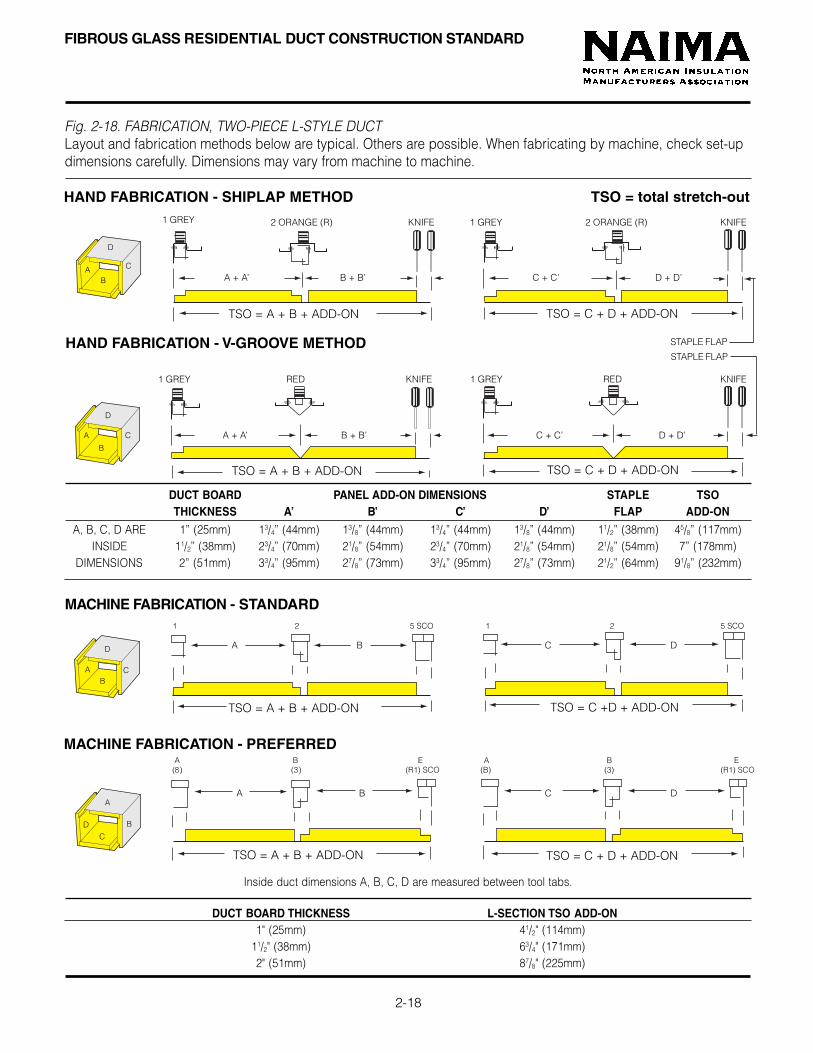
Fig. 2-18. FABRICATION, TWO-PIECE L-STYLE DUCTLayout and fabrication methods below are typical. Others are possible. When fabricating by machine, check set-updimensions carefully. Dimensions may vary from machine to machine.
MACHINE FABRICATION - STANDARD
MACHINE FABRICATION - PREFERRED
HAND FABRICATION - V-GROOVE METHOD
TSO = A + B + ADD-ON
TSO = A + B + ADD-ON
A B C D
A B C D
A + A’ B + B’ C + C’ D + D’
HAND FABRICATION - SHIPLAP METHOD TSO = total stretch-out 1 GREY 2 ORANGE (R) KNIFE 1 GREY 2 ORANGE (R) KNIFE
1 GREY RED KNIFE 1 GREY RED KNIFE
AB
C
D
A
B
C
D
AB
C
D
A
B
C
D
1 2 5 SCO 1 2 5 SCO
DUCT BOARD THICKNESS L-SECTION TSO ADD-ON1" (25mm) 41/2" (114mm)
11/2" (38mm) 63/4" (171mm)2" (51mm) 87/8" (225mm)
A B E A B E (8) (3) (R1) SCO (B) (3) (R1) SCO
DUCT BOARD PANEL ADD-ON DIMENSIONS STAPLE TSOTHICKNESS A’ B’ C’ D’ FLAP ADD-ON
A, B, C, D ARE 1” (25mm) 13/4” (44mm) 13/8” (44mm) 13/4” (44mm) 13/8” (44mm) 11/2” (38mm) 45/8” (117mm)INSIDE 11/2” (38mm) 23/4” (70mm) 21/8” (54mm) 23/4” (70mm) 21/8” (54mm) 21/8” (54mm) 7” (178mm)
DIMENSIONS 2” (51mm) 33/4” (95mm) 27/8” (73mm) 33/4” (95mm) 27/8” (73mm) 21/2” (64mm) 91/8” (232mm)
TSO = C + D + ADD-ON
A + A’ B + B’ C + C’ D + D’
TSO = C + D + ADD-ON
TSO = C +D + ADD-ON
TSO = C + D + ADD-ON
STAPLE FLAP
TSO = A + B + ADD-ON
STAPLE FLAP
TSO = A + B + ADD-ON
Inside duct dimensions A, B, C, D are measured between tool tabs.

MACHINE FABRICATION - STANDARD
FIBROUS GLASS RESIDENTIAL DUCT CONSTRUCTION STANDARD
MACHINE FABRICATION - PREFERRED
2-19
A B C D
A B C D
A C
A + A’ B TSO C + C’ D TSO
HAND FABRICATION - HAND TOOL METHOD TSO = total stretch-out
Fig. 2-19. FABRICATION, FOUR-PIECE DUCTLayout and fabrication methods below are typical. Others are possible. When fabricating by machine, check set-updimensions carefully. Dimensions may vary from machine to machine.
1 GREY 1 GREY KNIFE KNIFE GREY GREY KNIFE KNIFE
A
B
C
D
A
B
C
D
A
B
C
D
1 R1 SCO 8 5 SCO 1 5 SCO 8 5 SCO
Inside duct dimensions A, B, C, D are measured between tool tabs.
A G SCO F E A G SCO F E (8) (5) SCO (1) (R1) SCO (8) (5) SCO (1) (R1) SCO
DUCT BOARD PANEL ADD-ON DIMENSIONS STAPLE B & DTHICKNESS A’ & C’ B’ & D’ FLAP TSO ADD-ON
A, B, C, D ARE 1" (25mm) 13/4" (44mm) 1" (25mm) 11/2" (38mm) 4" (102mm)INSIDE 11/2" (38mm) 23/4" (70mm) 11/2" (38mm) 21/8" (54mm) 53/4" (146mm)
DIMENSIONS 2" (51mm) 33/4" (95mm) 2" (51mm) 21/2" (64mm) 7" (178mm)
A TSO B TSO C TSO D TSO
A TSO B TSO C TSO D TSO
STAPLE FLAP
STAPLE FLAP
DUCT BOARD STANDARD TSO ADD-ON PREFERRED TSO ADD-ON STAPLE FLAPTHICKNESS PANELS A & C PANELS B & D PANELS A & C PANELS B & D (REFERENCE)
A, B, C, D ARE 1" (25mm) 11/2" (38mm) 41/4" (108mm) 41/4" (108mm) 11/2" (38mm) 15/8" (41mm)INSIDE 11/2" (38mm) 21/2" (64mm) 53/4" (146mm) 53/4" (146mm) 21/2" (64mm) 21/8" (54mm)
DIMENSIONS 2" (51mm) 31/2" (89mm) 71/4" (184mm) 71/4" (184mm) 31/2" (89mm) 25/8" (67mm)
B + B’ D + D’
STAPLE FLAP

FIBROUS GLASS RESIDENTIAL DUCT CONSTRUCTION STANDARD
2-20
ONE PIECE STRETCH-OUT DIMENSIONS IN INCHES, 1" DUCT BOARDDUCT HEIGHT, in.
66666 88888 1010101010 1212121212 1414141414 1616161616 1818181818 2020202020 2222222222 2424242424 2626262626 2828282828 3030303030 3232323232 3434343434 363636363666666 32 36 40 44 48 52 56 60 64 68 72 76 80 84 88 9288888 36 40 44 48 52 56 60 64 68 72 76 80 84 88 92
1010101010 40 44 48 52 56 60 64 68 72 76 80 84 88 921212121212 44 48 52 56 60 64 68 72 76 80 84 88 921414141414 48 52 56 60 64 68 72 76 80 84 88 921616161616 52 56 60 64 68 72 76 80 84 88 921818181818 56 60 64 68 72 76 80 84 88 922020202020 60 64 68 72 76 80 84 88 922222222222 64 68 72 76 80 84 88 922424242424 68 72 76 80 84 88 922626262626 72 76 80 84 88 922828282828 76 80 84 88 923030303030 80 84 88 923232323232 84 88 923434343434 88 923636363636 92
ONE PIECE STRETCH-OUT DIMENSIONS IN MILLIMETERS, 25mm DUCT BOARDDUCT HEIGHT, mm.
150 200 250 300 350 400 450 500 550 600 650 700 750 800 850 900150 800 900 1000 1100 1200 1300 1400 1500 1600 1700 1800 1900 2000 2100 2200 2300200 900 1000 1100 1200 1300 1400 1500 1600 1700 1800 1900 2000 2100 2200 2300250 1000 1100 1200 1300 1400 1500 1600 1700 1800 1900 2000 2100 2200 2300300 1100 1200 1300 1400 1500 1600 1700 1800 1900 2000 2100 2200 2300350 1200 1300 1400 1500 1600 1700 1800 1900 2000 2100 2200 2300400 1300 1400 1500 1600 1700 1800 1900 2000 2100 2200 2300450 1400 1500 1600 1700 1800 1900 2000 2100 2200 2300500 1500 1600 1700 1800 1900 2000 2100 2200 2300550 1600 1700 1800 1900 2000 2100 2200 2300600 1700 1800 1900 2000 2100 2200 2300650 1800 1900 2000 2100 2200 2300700 1900 2000 2100 2200 2300750 2000 2100 2200 2300800 2100 2200 2300850 2200 2300900 2300
NOTE: These tables assume the total stretch-out (add-on)dimension is 8". If the process used results in a differentstretch-out dimension, these tables must be modifiedaccordingly.
NOTE: These tables assume the total stretch-out (add-on)dimension is 200mm. If the process used results in a differentstretch-out dimension, these tables must be modifiedaccordingly.
DUCTWIDTH
in.
DUCTWIDTH
mm.

FIBROUS GLASS RESIDENTIAL DUCT CONSTRUCTION STANDARD
2-21
BOARD UTILIZATION, ONE PIECE DUCT, 1" DUCT BOARD, FT2 PER LINEAL FOOT OF DUCT
DUCT HEIGHT, in.6 8 10 12 14 16 18 20 22 24 26 28 30 32 34 36
6 2.67 3.00 3.33 3.67 4.00 4.33 4.67 5.00 5.33 5.67 6.00 6.33 6.67 7.00 7.33 7.678 3.00 3.33 3.67 4.00 4.33 4.67 5.00 5.33 5.67 6.00 6.33 6.67 7.00 7.33 7.67
10 3.33 3.67 4.00 4.33 4.67 5.00 5.33 5.67 6.00 6.33 6.67 7.00 7.33 7.6712 3.67 4.00 4.33 4.67 5.00 5.33 5.67 6.00 6.33 6.67 7.00 7.33 7.6714 4.00 4.33 4.67 5.00 5.33 5.67 6.00 6.33 6.67 7.00 7.33 7.6716 4.33 4.67 5.00 5.33 5.67 6.00 6.33 6.67 7.00 7.33 7.6718 4.67 5.00 5.33 5.67 6.00 6.33 6.67 7.00 7.33 7.6720 5.00 5.33 5.67 6.00 6.33 6.67 7.00 7.33 7.6722 5.33 5.67 6.00 6.33 6.67 7.00 7.33 7.6724 5.67 6.00 6.33 6.67 7.00 7.33 7.6726 6.00 6.33 6.67 7.00 7.33 7.6728 6.33 6.67 7.00 7.33 7.6730 6.67 7.00 7.33 7.6732 7.00 7.33 7.6734 7.33 7.6736 7.67
BOARD UTILIZATION, ONE PIECE DUCT, 25mm DUCT BOARD, m2 PER LINEAL METER OF DUCTDUCT HEIGHT, mm.
150 200 250 300 350 400 450 500 550 600 650 700 750 800 850 900150 0.8 0.9 1.0 1.1 1.2 1.3 1.4 1.5 1.6 1.7 1.8 1.9 2.0 2.1 2.2 2.3200 0.9 1.0 1.1 1.2 1.3 1.4 1.5 1.6 1.7 1.8 1.9 2.0 2.1 2.2 2.3250 1.0 1.1 1.2 1.3 1.4 1.5 1.6 1.7 1.8 1.9 2.0 2.1 2.2 2.3300 1.1 1.2 1.3 1.4 1.5 1.6 1.7 1.8 1.9 2.0 2.1 2.2 2.3350 1.2 1.3 1.4 1.5 1.6 1.7 1.8 1.9 2.0 2.1 2.2 2.3400 1.3 1.4 1.5 1.6 1.7 1.8 1.9 2.0 2.1 2.2 2.3450 1.4 1.5 1.6 1.7 1.8 1.9 2.0 2.1 2.2 2.3500 1.5 1.6 1.7 1.8 1.9 2.0 2.1 2.2 2.3550 1.6 1.7 1.8 1.9 2.0 2.1 2.2 2.3600 1.7 1.8 1.9 2.0 2.1 2.2 2.3650 1.8 1.9 2.0 2.1 2.2 2.3700 1.9 2.0 2.1 2.2 2.3750 2.0 2.1 2.2 2.3800 2.1 2.2 2.3850 2.2 2.3900 2.3
NOTE: This table is based on a total add-on allowance of 200mm.If the process and tools used result in a different add-onallowance, these tables must be modified accordingly.
NOTE: This table is based on a total add-on allowance of 8".If the process and tools used result in a different add-onallowance, these tables must be modified accordingly.
DUCTWIDTH
in.
DUCTWIDTH
mm.

FIBROUS GLASS RESIDENTIAL DUCT CONSTRUCTION STANDARD
2-22
DUCT HEIGHT, in. 6 8 10 12 14 16 18 20 22 24 26 28 30 32 34 36
6 36 40 44 48 52 56 60 64 68 72 76 80 84 88 92 968 40 44 48 52 56 60 64 68 72 76 80 84 88 92 96
10 44 48 52 56 60 64 68 72 76 80 84 88 92 9612 48 52 56 60 64 68 72 76 80 84 88 92 9614 52 56 60 64 68 72 76 80 84 88 92 9616 56 60 64 68 72 76 80 84 88 92 9618 60 64 68 72 76 80 84 88 92 9620 64 68 72 76 80 84 88 92 9622 68 72 76 80 84 88 92 9624 72 76 80 84 88 92 9626 76 80 84 88 92 9628 80 84 88 92 9630 84 88 92 9632 88 92 9634 92 9636 96
ONE PIECE STRETCH-OUT DIMENSIONS IN MILLIMETERS, 38mm DUCT BOARDDUCT HEIGHT, mm.
150 200 250 300 350 400 450 500 550 600 650 700 750 800 850 900150 900 1000 1100 1200 1300 1400 1500 1600 1700 1800 1900 2000 2100 2200 2300 2400200 1000 1100 1200 1300 1400 1500 1600 1700 1800 1900 2000 2100 2200 2300 2400250 1100 1200 1300 1400 1500 1600 1700 1800 1900 2000 2100 2200 2300 2400300 1200 1300 1400 1500 1600 1700 1800 1900 2000 2100 2200 2300 2400350 1300 1400 1500 1600 1700 1800 1900 2000 2100 2200 2300 2400400 1400 1500 1600 1700 1800 1900 2000 2100 2200 2300 2400450 1500 1600 1700 1800 1900 2000 2100 2200 2300 2400500 1600 1700 1800 1900 2000 2100 2200 2300 2400550 1700 1800 1900 2000 2100 2200 2300 2400600 1800 1900 2000 2100 2200 2300 2400650 1900 2000 2100 2200 2300 2400700 2000 2100 2200 2300 2400750 2100 2200 2300 2400800 2200 2300 2400850 2300 2400900 2400
ONE PIECE STRETCH-OUT DIMENSIONS IN INCHES, 11/2” DUCT BOARD
NOTE: These tables assume the total stretch-out (add-on)dimension is 300mm. If the process used results in adifferent stretch-out dimension, these tables must bemodified accordingly.
NOTE: These tables assume the total stretch-out (add-on)dimension is 12". If the process used results in a differentstretch-out dimension, these tables must be modifiedaccordingly.
DUCTWIDTH
in.
DUCTWIDTH
mm.

FIBROUS GLASS RESIDENTIAL DUCT CONSTRUCTION STANDARD
2-23
BOARD UTILIZATION, ONE PIECE DUCT, 11/2" DUCT BOARD, FT2 PER LINEAL FOOT OF DUCTDUCT HEIGHT, in.
6 8 10 12 14 16 18 20 22 24 26 28 30 32 34 366 3.00 3.33 3.67 4.00 4.33 4.67 5.00 5.33 5.67 6.00 6.33 6.67 7.00 7.33 7.67 8.008 3.33 3.67 4.00 4.33 4.67 5.00 5.33 5.67 6.00 6.33 6.67 7.00 7.33 7.67 8.00
10 3.67 4.00 4.33 4.67 5.00 5.33 5.67 6.00 6.33 6.67 7.00 7.33 7.67 8.0012 4.00 4.33 4.67 5.00 5.33 5.67 6.00 6.33 6.67 7.00 7.33 7.67 8.0014 4.33 4.67 5.00 5.33 5.67 6.00 6.33 6.67 7.00 7.33 7.67 8.0016 4.67 5.00 5.33 5.67 6.00 6.33 6.67 7.00 7.33 7.67 8.0018 5.00 5.33 5.67 6.00 6.33 6.67 7.00 7.33 7.67 8.0020 5.33 5.67 6.00 6.33 6.67 7.00 7.33 7.67 8.0022 5.67 6.00 6.33 6.67 7.00 7.33 7.67 8.0024 6.00 6.33 6.67 7.00 7.33 7.67 8.0026 6.33 6.67 7.00 7.33 7.67 8.0028 6.67 7.00 7.33 7.67 8.0030 7.00 7.33 7.67 8.0032 7.33 7.67 8.0034 7.67 8.0036 8.00
BOARD UTILIZATION, ONE PIECE DUCT, 38mm DUCT BOARD, m2 PER LINEAL METER OF DUCTDUCT HEIGHT, mm.
150 200 250 300 350 400 450 500 550 600 650 700 750 800 850 900150 0.9 1.0 1.1 1.2 1.3 1.4 1.5 1.6 1.7 1.8 1.9 2.0 2.1 2.2 2.3 2.4200 1.0 1.1 1.2 1.3 1.4 1.5 1.6 1.7 1.8 1.9 2.0 2.1 2.2 2.3 2.4250 1.1 1.2 1.3 1.4 1.5 1.6 1.7 1.8 1.9 2.0 2.1 2.2 2.3 2.4300 1.2 1.3 1.4 1.5 1.6 1.7 1.8 1.9 2.0 2.1 2.2 2.3 2.4350 1.3 1.4 1.5 1.6 1.7 1.8 1.9 2.0 2.1 2.2 2.3 2.4400 1.4 1.5 1.6 1.7 1.8 1.9 2.0 2.1 2.2 2.3 2.4450 1.5 1.6 1.7 1.8 1.9 2.0 2.1 2.2 2.3 2.4500 1.6 1.7 1.8 1.9 2.0 2.1 2.2 2.3 2.4550 1.7 1.8 1.9 2.0 2.1 2.2 2.3 2.4600 1.8 1.9 2.0 2.1 2.2 2.3 2.4650 1.9 2.0 2.1 2.2 2.3 2.4700 2.0 2.1 2.2 2.3 2.4750 2.1 2.2 2.3 2.4800 2.2 2.3 2.4850 2.3 2.4900 2.4
NOTE: This table is based on a total add-on allowance of 300mm.If the process and tools used result in a different add-onallowance, these tables must be modified accordingly.
NOTE: This table is based on a total add-on allowance of 12".If the process and tools used result in a different add-onallowance, these tables must be modified accordingly.
DUCTWIDTH
in.
DUCTWIDTH
mm.....

FIBROUS GLASS RESIDENTIAL DUCT CONSTRUCTION STANDARD
ONE PIECE STRETCH-OUT DIMENSIONS IN MILLIMETERS, 51mm DUCT BOARD
DUCT HEIGHT, mm 150 200 250 300 350 400 450 500 550 600 650 700 750 800 850 900 950 1000 1050
150 1000 1100 1200 1300 1400 1500 1600 1700 1800 1900 2000 2100 2200 2300 2400 2500 2600 2700 2800200 1100 1200 1300 1400 1500 1600 1700 1800 1900 2000 2100 2200 2300 2400 2500 2600 2700 2800250 1200 1300 1400 1500 1600 1700 1800 1900 2000 2100 2200 2300 2400 2500 2600 2700 2800300 1300 1400 1500 1600 1700 1800 1900 2000 2100 2200 2300 2400 2500 2600 2700 2800350 1400 1500 1600 1700 1800 1900 2000 2100 2200 2300 2400 2500 2600 2700 2800400 1500 1600 1700 1800 1900 2000 2100 2200 2300 2400 2500 2600 2700 2800450 1600 1700 1800 1900 2000 2100 2200 2300 2400 2500 2600 2700 2800500 1700 1800 1900 2000 2100 2200 2300 2400 2500 2600 2700 2800550 1800 1900 2000 2100 2200 2300 2400 2500 2600 2700 2800600 1900 2000 2100 2200 2300 2400 2500 2600 2700 2800650 2000 2100 2200 2300 2400 2500 2600 2700 2800700 2100 2200 2300 2400 2500 2600 2700 2800750 2200 2300 2400 2500 2600 2700 2800800 2300 2400 2500 2600 2700 2800850 2400 2500 2600 2700 2800900 2500 2600 2700 2800950 2600 2700 28001000 2700 28001050 2800
2-24
ONE PIECE STRETCH-OUT DIMENSIONS IN INCHES, 2" DUCT BOARD
NOTE: This table assumes the total stretch-out (add-on)dimension is 400mm. If the process used results in a differentstretch-out (add-on) dimension, this table must bemodified accordingly.
NOTE: This table assumes the total stretch-out (add-on)dimension is 16". If the process used results in a differentstretch-out (add-on) dimension, this table must bemodified accordingly.
DU112CTWIDTH
mm
DUCTWIDTH
in.
NOTE: Maximum unreinforced size at 1/2" w.g. is 36" for800EI board and 42" for 1400EI board.
NOTE: Maximum unreinforced size at 1/2" w.g. is 900mm for800EI board and 1050mm for 1400EI board.
DUCT HEIGHT, in. 6 8 10 12 14 16 18 20 22 24 26 28 30 32 34 36 38 40 42
6 40 44 48 52 56 60 64 68 72 76 80 84 88 92 96 100 104 108 1128 44 48 52 56 60 64 68 72 76 80 84 88 92 96 100 104104104104104 108 11210 48 52 56 60 64 68 72 76 80 84 88 92 96 100 104 108 11212 52 56 60 64 68 72 76 80 84 88 92 96 100 104 108 11214 56 60 64 68 72 76 80 84 88 92 96 100 104 108 11216 60 64 68 72 76 80 84 88 92 96 100 104 108 11218 64 68 72 76 80 84 88 92 96 100 104 108 11220 68 72 76 80 84 88 92 96 100 104 108 11222 72 76 80 84 88 92 96 100 104 108 11224 76 80 84 88 92 96 100 104 108 11226 80 84 88 92 96 100 104 108 11228 84 88 92 96 100 104 108 11230 88 92 96 100 104 108 11232 92 96 100 104 108 11234 96 100 104 108 11236 100 104 108 11238 104 108 11240 108 11242 112

DUCT HEIGHT, in.6 8 10 12 14 16 18 20 22 24 26 28 30 32 34 36 38 40 42
6 3.33 3.67 4.00 4.33 4.67 5.00 5.33 5.67 6.00 6.33 6.67 7.00 7.33 7.67 8.00 8.33 8.67 9.00 9.338 3.67 4.00 4.33 4.67 5.00 5.33 5.67 6.00 6.33 6.67 7.00 7.33 7.67 8.00 8.33 8.67 9.00 9.3310 4.00 4.33 4.67 5.00 5.33 5.67 6.00 6.33 6.67 7.00 7.33 7.67 8.00 8.33 8.67 9.00 9.3312 4.33 4.67 5.00 5.33 5.67 6.00 6.33 6.67 7.00 7.33 7.67 8.00 8.33 8.67 9.00 9.3314 4.67 5.00 5.33 5.67 6.00 6.33 6.67 7.00 7.33 7.67 8.00 8.33 8.67 9.00 9.3316 5.00 5.33 5.67 6.00 6.33 6.67 7.00 7.33 7.67 8.00 8.33 8.67 9.00 9.3318 5.33 5.67 6.00 6.33 6.67 7.00 7.33 7.67 8.00 8.33 8.67 9.00 9.3320 5.67 6.00 6.33 6.67 7.00 7.33 7.67 8.00 8.33 8.67 9.00 9.3322 6.00 6.33 6.67 7.00 7.33 7.67 8.00 8.33 8.67 9.00 9.3324 6.33 6.67 7.00 7.33 7.67 8.00 8.33 8.67 9.00 9.3326 6.67 7.00 7.33 7.67 8.00 8.33 8.67 9.00 9.3328 7.00 7.33 7.67 8.00 8.33 8.67 9.00 9.3330 7.33 7.67 8.00 8.33 8.67 9.00 9.3332 7.67 8.00 8.33 8.67 9.00 9.3334 8.00 8.33 8.67 9.00 9.3336 8.33 8.67 9.00 9.3338 8.67 9.00 9.3340 9.00 9.3342 9.33
FIBROUS GLASS RESIDENTIAL DUCT CONSTRUCTION STANDARD
BOARD UTILIZATION, ONE PIECE DUCT, 51mm DUCT BOARD, m2 PER LINEAL METER OF DUCT
DUCT HEIGHT, mm150 200 250 300 350 400 450 500 550 600 650 700 750 800 850 900 950 1000 1050
150 1.0 1.1 1.2 1.3 1.4 1.5 1.6 1.7 1.8 1.9 2.0 2.1 2.2 2.3 2.4 2.5 2.6 2.7 2.8200 1.1 1.2 1.3 1.4 1.5 1.6 1.7 1.8 1.9 2.0 2.1 2.2 2.3 2.4 2.5 2.6 2.7 2.8250 1.2 1.3 1.4 1.5 1.6 1.7 1.8 1.9 2.0 2.1 2.2 2.3 2.4 2.5 2.6 2.7 2.8300 1.3 1.4 1.5 1.6 1.7 1.8 1.9 2.0 2.1 2.2 2.3 2.4 2.5 2.6 2.7 2.8350 1.4 1.5 1.6 1.7 1.8 1.9 2.0 2.1 2.2 2.3 2.4 2.5 2.6 2.7 2.8400 1.5 1.6 1.7 1.8 1.9 2.0 2.1 2.2 2.3 2.4 2.5 2.6 2.7 2.8450 1.6 1.7 1.8 1.9 2.0 2.1 2.2 2.3 2.4 2.5 2.6 2.7 2.8500 1.7 1.8 1.9 2.0 2.1 2.2 2.3 2.4 2.5 2.6 2.7 2.8550 1.8 1.9 2.0 2.1 2.2 2.3 2.4 2.5 2.6 2.7 2.8600 1.9 2.0 2.1 2.2 2.3 2.4 2.5 2.6 2.7 2.8650 2.0 2.1 2.2 2.3 2.4 2.5 2.6 2.7 2.8700 2.1 2.2 2.3 2.4 2.5 2.6 2.7 2.8750 2.2 2.3 2.4 2.5 2.6 2.7 2.8800 2.3 2.4 2.5 2.6 2.7 2.8850 2.4 2.5 2.6 2.7 2.8900 2.5 2.6 2.7 2.8950 2.6 2.7 2.81000 2.7 2.81050 2.8
2-25
BOARD UTILIZATION, ONE PIECE DUCT, 2" DUCT BOARD, FT2 PER LINEAL FOOT OF DUCT
NOTE: This table assumes the total stretch-out (add-on)dimension is 400mm. If the process used results in adifferent stretch-out (add-on) dimension, this table mustbe modified accordingly.
NOTE: This table assumes the total stretch-out (add-on)dimension is 16". If the process used results in a differentstretch-out (add-on) dimension, this table must bemodified accordingly.
DUCTWIDTH
mm
DUCTWIDTH
in.
NOTE: Maximum unreinforced size at 1/2" w.g. is 36" for800EI board and 42" for 1400EI board.
NOTE: Maximum unreinforced size at 1/2" w.g. is 900mm for800EI board and 1050mm for 1400EI board.

FIBROUS GLASS RESIDENTIAL DUCT CONSTRUCTION STANDARD
2-26
FABRICATION OF DUCT MODULE
3. While holding the duct canted over at about 30o beyondsquare, staple the longitudinal flap approximately 2" (50mm)on centers. Staples shall be outward clinching, galvanizedsteel, 1/2” (13mm) long, crown width 0.400” (10mm) (min.),flat wire, 0.040” x 0.020” (1.2 x 0.5mm) (min.).
1. Cut shiplaps and corner grooves with hand toolsor by machine as shown on pages 2-16 through 2-19.Remove groove scrap. Lifting board as shown willmake it easier to remove shiplap groove scrap.
4. Complete the longitudinal seam according toprocedures shown in Section V, CLOSURE, pagedepending on the approved closure method chosen.(Pressure sensitive tape shown above.)
2. Fold to form the duct section, making sure endsare flush and seated properly in the shoulder of theshiplap edge.

FIBROUS GLASS RESIDENTIAL DUCT CONSTRUCTION STANDARD
2-27
JOINING TWO DUCT MODULES
1. Slit facing flaps back at corners, making sure you donot cut below the male shiplap shoulder or into insideduct surfaces.
3. Staple flaps on all four sides with ½” (13mm) (minimum)outward clinching staples approximately 2" (50mm)on centers.
2. Push the two modules together. Make sure male andfemale shiplaps are tightly fitted together.
4. Complete closure of circumferential joint with UL 181Alisted closure. The minimum width pressure sensitive tapefor 1” board is 21/2”. Three inch tape is recommended for11/2” and required for 2” board. Duct board surface must beclean and dry. (Pressure sensitive tape shown above.)

FIBROUS GLASS RESIDENTIAL DUCT CONSTRUCTION STANDARD
2-28
3. Using shiplap cutter to make female shiplap. Cutter ispositioned to cut into inside of duct wall.
PREFORMED ROUND FIBROUS GLASS DUCT
Preformed round fibrous glass duct meetsrequirements of NFPA 90A and 90B, and is UL 181listed as a Class 1 Air Duct.
A male-female shiplap joint system, similar to that offlat fibrous glass duct board, is used to makeconnections between duct sections.
Closure is accomplished using materials and methodsdescribed in Section V of this Standard, except thatstaples are not required.
FABRICATION OF PREFORMED ROUNDSTRAIGHT SECTIONS
Straight sections of preformed round fibrous glassduct have factory-formed male and female shiplap ends.When cutting to length with a straight knife cut, theseshiplaps must be replaced using the red slipjoint cutter.
For male shiplap: Place cutter over end of duct withblade positioned to cut into exterior of duct wall.Draw cutter completely around duct, then diagonallyacross the outer edge to permit removal of excessstrip of fibrous glass.
For female shiplap: Reverse position of cutter so it cutsinto inner surface of duct. Follow same procedureas for male shiplap. Remove excess strip of fibrous glass.
2. Using shiplap cutter to make male shiplap. Cutter ispositioned to cut into exterior of duct wall.
1. Preformed round duct sections are joined with male andfemale shiplaps. Joints are taped; staples are not required.

FIBROUS GLASS RESIDENTIAL DUCT CONSTRUCTION STANDARD
2-29
4. Assembling 90° 2-piece elbow with sheet metalsleeve.
5. Using saddle as a template to mark hole in main ductfor branch connection.
6. Assembling 90° 3-piece elbow. Duct material must beremoved for clearance over sheet metal elbow.
FABRICATING FITTINGS WITH PREFORMEDROUND FIBROUS GLASS DUCT
ELBOWS:Use standard sheet metal practice to determine throatdimensions. Mark all cuts for mitering. A fine-tooth sawand miter box are recommended to ensure straight,accurate cuts.
90° 2-Piece Elbow:Make one 45° angle cut. Insert metal elbow in oneopening and align other piece of duct to fit tightly.Seal with tape.
90° 3-Piece Elbow:Make two 221/2° angle cuts. Make 180° cut inside backof mitered section tapering from zero thickness on eitherside to about half the wall thickness at back. Removematerial to provide clearance over metal elbow.Assemble mitered section, align, and seal with tape.
Branch Connection:Fabricate sheet metal saddle and branch collarto conform to outside diameter of main duct, andinsert a sheet metal collar to support branchconnection properly.
Using the saddle as a template, mark opening in mainduct to conform to inside diameter of branch duct. Takecare to maintain branch angle with knife.
Fasten sheet metal saddle in place. Secure branch ductin place and seal with tape as recommended by roundduct manufacturer. NOTE: Staples are not required.

FIBROUS GLASS RESIDENTIAL DUCT CONSTRUCTION STANDARD
2-30
CLOSURE OF PREFORMED ROUND DUCTJOINTS
Closure of circumferential joints in preformed roundduct is accomplished using materials and proceduresin compliance with the manufacturer’s UL 181 listing.NOTE: Staples are not used in making closures withrigid round fibrous glass duct.
If using pressure sensitive tape, center tape over jointand overlap ends 3" (75mm) (minimum).
Rub tape firmly with sealing tool until scrim pattern ofduct facing shows through tape to assure an air-tightseal.
If using heat activated tape, take care to apply heatuniformly around entire circumference of duct. Check tomake sure all temperature indicator dots change color.
7. Applying pressure sensitive tape to joint of preformedround duct. Tape is centered over joint.
8. Closure with pressure sensitive tape. Rub tape firmlywith sealing tool until scrim pattern of duct facing showsthrough tape.
9. Closure with heat activated tape. Apply heat uniformlyall around duct. Make sure all temperature indicator dotschange color.

FIBROUS GLASS RESIDENTIAL DUCT CONSTRUCTION STANDARD
2-31
90 degree elbow, 3 gore 90 degree elbow, 5 gore
90 degree tee Offset Reducer
Fig. 2-17. Typical ten-sided fibrous glass duct fittings.
Ten-sided fibrous glass duct is approximately round in cross-section, and is an acceptable substitute for rigid round duct.
Sections of ten-sided duct up to 10 ft (3.05m) may befabricated from standard fibrous glass duct board witha grooving machine equipped with the required tooling.A gauge is used to set the spacing between groovecutting tools.
Circumferential joints may be shiplapped or butt-edged.Male and female ends should be fabricated while thematerial is in flat board form.
Internal metal sleeves must be used on all return air ducts,and on supply ducts without shiplap joints.
Typical fittings, such as elbows, branch connections, tees,and offsets can be fabricated with ten-sided fibrous glassduct. Examples are shown below.
FABRICATION WITH TEN-SIDED FIBROUSGLASS DUCT
10. Duct board grooving machine set up for cuttingten-sided fibrous glass duct.

FIBROUS GLASS RESIDENTIAL DUCT CONSTRUCTION STANDARD
2-32
TEN-SIDED DUCT BOARD UTILIZATION
The table below shows options available in convertingstandard duct board sizes into ten-sided duct. The tableis based on ideal tool settings. Because of variation inblade settings, tool bar height, and size of sheet metalfittings which might be used with ten-sided duct, thefabricator should always check material made on hisspecific machine for dimensional accuracy beforeproducing large quantities of duct. He should alsoselect the best combination of duct board lengthversus drop-off which fits the specific ten-sidedduct application.
Be certain to check your specific tool arrangement toverify these values.
Example:20 ft. (6m) lengths of 5" (150mm) nominal insidediameter ten-sided duct can be made in two ways: (1) With two sections 10 ft. (3.0 m) long; (2) With five sections 4 ft. (1.2 m) long.Both involve minimum drop-off. Use of 20 ft. (6m) often-sided duct in 10 ft. (3.0 m) lengths has theadvantage of requiring only one circumferential joint,compared to four required for 4-section construction.In making 4 ft. (1.2 m) long, 7" (178mm) nominal insidediameter ten-sided duct, 10 ft. (3.0 m) duct board will yieldfour sections with essentially no drop-off.8 ft. (2.4 m) duct board yields 3 sections with2.3 sq.ft. (.22 m2) of scrap.
STRETCH-OUT TEN-SIDED DUCT Nominal Inside 1"(25mm) duct board 11/2"(38mm) duct board Diameter Full Section 10 sides Half Section 5 sides Full Section10 sides Half Section 5 sides
in. (mm) in. (mm) in. (mm) in. (mm) in. (mm)5 (127) 233/4 (603) 123/8 (314) 273/4 (705) 143/8 (365)6 (152) 267/8 (683) 1315/16 (354) 307/8 (784) 1515/16 (405)7 (178) 30 (762) 151/2 (394) 34 (864) 171/2 (445)8 (203) 331/8 (841) 171/16 (433) 371/8 (943) 19 (483)9 (229) 361/4 (921) 185/8 (473) 401/4 (1022) 205/8 (524)
10 (254) 397/16 (1002) 201/4 (514) 437/16 (1103) 221/4 (565)12 (305) 453/4 (1162) 233/8 (594) 4611/16 (1186) 253/8 (645)14 (356) 52 (1321) 261/2 (673) 56 (1422) 281/2 (724)16 (406) 581/4 (1480) 295/8 (752) 621/4 (1581) 315/8 (803)18 (457) 649/16 (1640) 323/4 (832) 689/16 (1745) 343/4 (883)20 (508) 7013/16 (1799) 3515/16 (913) 7413/16 (1900) 3715/16 (964)22 (559) 771/8 (1959) 391/16 (992) 811/8 (2061) 411/16 (1043)24 (610) 833/8 (2118) 421/4 (1073) 873/8 (2219) 441/4 (1124)26 (660) 8911/16 (2278) 453/8 (1153) 9311/16 (2380) 473/8 (1203)28 (711) 96 (2438) 481/2 (1226) 100 (2540) 501/2 (1283)30 (762) 1021/4 (2597) 515/8 (1311) 1061/4 (2699) 535/8 (1362)
NOTE: Full section denotes 10 sides plus stapling flap. Half section denotes 5 sides plus stapling flap. Joining two half sections requires two longitudinal joints.

FIBROUS GLASS RESIDENTIAL DUCT CONSTRUCTION STANDARD
10 ft. (3.05m) ducts from 4 ft. (1.2m) duct board
2-33
Nominal inside diam., No. of Material left, Drop-off,in (mm) sections in. (mm) ft2 (m2)5 (127) 2 1 (25) 0.8 (0.24)6 (152) 11/2 71/2 (191) 6.3 (1.92)7 (178) 11/2 27/8 (73) 2.4 (0.73)8 (204) 1 151/8* (384) 12.6 (3.84)9 (229) 1 12 (305) 10.0 (3.05)
10 (254) 1 87/8 (225) 7.4 (2.25)11 (279) 1 53/4 (146) 4.8 (1.46)12 (305) 1 25/8 (67) 2.2 (0.67)13 (330) 1/2 231/4* (591) 19.4 (5.91)14 (356) 1/2 215/8* (549) 18.0 (5.48)15 (381) 1/2 201/8* (511) 16.8 (5.12)16 (406) 1/2 181/2* (470) 15.4 (4.69)17 (432) 1/2 17* (432) 14.2 (4.33)18 (457) 1/2 153/8* (390) 12.8 (3.90)19 (483) 1/2 137/8* (352) 11.6 (3.53)20 (508) 1/2 121/4* (311) 10.2 (3.11)
4 ft. (1.2m) ducts from 8 ft. (2.44m) duct boardNominal inside diam., No. of Material left, Drop-off,
in (mm) sections in. (mm) ft2 (m2)5 (127) 4 2 (51) 0.7 (0.24)6 (152) 31/2 21/4 (57) 0.8 (1.37)7 (178) 3 63/4 (171) 2.3 (0.70)8 (204) 21/2 131/4* (337) 4.4 (1.34)9 (229) 21/2 51/2 (140) 1.8 (0.55)
10 (254) 2 173/4* (451) 5.9 (1.80)11 (279) 2 111/2 (292) 3.8 (1.16)12 (305) 2 51/4 (133) 1.8 (0.55)13 (330) 11/2 223/4* (578) 7.6 (2.32)14 (356) 11/2 18* (457) 6.0 (1.83)15 (381) 11/2 133/8* (340) 4.5 (1.37)16 (406) 11/2 85/8 (219) 2.9 (0.88)17 (432) 11/2 4 (102) 2.7 (0.82)18 (457) 1 317/8* (810) 21.3 (6.49)19 (483) 1 283/4* (730) 19.2 (5.85)20 (508) 1 255/8* (651) 17.1 (5.18)
4 ft. (1.2m) ducts from 10 ft. (3.05m) duct boardNominal inside diam., No. of Material left, Drop-off,
in (mm) sections in. (mm) ft2 (m2)5 (127) 5 21/2 (25) 0.8 (0.24)6 (152) 4 131/2* (191) 4.5 (1.37)7 (178) 4 1 (73) 0.3 (0.09)8 (204) 31/2 43/8 (384) 1.5 (0.45)9 (229) 3 12 (305) 4.0 (1.22)
10 (254) 3 25/8 (225) 0.9 (2.25)11 (279) 21/2 137/8 (146) 4.6 (0.49)12 (305) 21/2 6 (152) 2.0 (0.61)13 (330) 2 23* (701) 7.7 (2.34)14 (356) 2 163/4* (425) 5.6 (1.71)15 (381) 2 101/2 (267) 3.5 (1.07)16 (406) 2 41/4 (108) 1.4 (0.43)17 (432) 11/2 28* (711) 23.3 (7.10)18 (457) 11/2 231/4* (591) 19.4 (5.91)19 (483) 11/2 185/8* (473) 15.5 (4.72)20 (508) 11/2 137/8* (352) 11.6 (3.53)
BOARD UTILIZATION, TEN-SIDED DUCT
The table below shows options available in convertingstandard duct board sizes into ten-sided duct. The tableis based on ideal tool settings. Because of variation inblade settings, tool bar height, and size of sheet metalfittings which might be used with ten-sided duct, thefabricator should always check material made on hisspecific machine for dimensional accuracy beforeproducing large quantities of duct. He should also selectthe best combination of duct board length versusdrop-off which fits the specific ten-sided duct application.
Example:20 ft. (6m) lengths of 5" (150mm) nominal inside diameterten-sided duct can be made in two ways: (1) With two sections 10 ft. (3.05 m) long; (2) With five sections 4 ft. (1.22m) long.Both involve minimum drop-off. Use of 20 ft. (6m) often-sided duct in 10 ft. (3.05 m) lengths has theadvantage of requiring only one circumferential joint,compared to four required for 4-section construction.In making 4 ft. (1.2 m) long, 7" (178mm) nominal insidediameter ten-sided duct, 10 ft. (3.05 m) duct board willyield four sections with essentially no drop-off.8 ft. (2.44m) duct board yields 3 sections with 2.3 sq.ft.(.22 m2) of scrap. Be certain to check your specific toolarrangement to verify these values.
*Denotes usable material.**Half sections are five-sided with stapling flap. Joining two halfsections requires two longitudinal joints.
TEN-SIDED DUCT BOARD UTILIZATION,1" (25mm) DUCT BOARD

FIBROUS GLASS RESIDENTIAL DUCT CONSTRUCTION STANDARD
2-34
Fig.2-32A. Removing scrap from grooved duct board.
Fig. 2-32C. Taping longitudinal joint of ten sided duct.
CLOSURE OF TEN SIDED FIBROUSGLASS DUCT
Longitudinal joints are formed in the same manner as inrectangular ducts.
After stapling, use closure materials listed in Section V,CLOSURE.
When two half sections are to be joined, it is easiest tomake the first joint while the duct board is in flat form.Sections must be tightly butted together before stapling.
Fig. 2-32B. Stapling longitudinal joint of ten sided duct.

FIBROUS GLASS RESIDENTIAL DUCT CONSTRUCTION STANDARD
SECTION III
EXTENDED PLENUMSYSTEM FABRICATION
NOTES TO SECTION III
1. FASTENER SCHEDULE#10 plated sheet metal screws, board thickness + 1/4" (6mm),with 21/2" (64mm) square or 3" (76mm) round galvanizedsteel washers, 0.028" (0.7mm) thick, volcano type, withturned edges facing away from duct board, 12” (300mm)(nominal) centers.
2. TAPE TAB SCHEDULEUL 181A pressure sensitive or heat activated tape,8" (200mm) nominal length, on 12" (300mm) nominal centers,at least one per side. Refer to Section V, CLOSURE.
3. SHIPLAP ORIENTATIONMale shiplap ends of duct modules and fittings alwaysface TOWARD the equipment. Female shiplap endsalways face AWAY from the equipment.
3-1

FIBROUS GLASS RESIDENTIAL DUCT CONSTRUCTION STANDARD
3-2
EXTENDED PLENUM SYSTEM
Fibrous glass ducts extend from central equipmentsupplying run-outs to individual room registers.Run-outs may be fibrous glass duct, preformed roundduct, ten-sided duct, insulated flexible duct, or insulatedmetal duct. Systems may either be simple (i.e., a straightrun of duct of one size or complex (including reducers,branches, offsets and other fittings), depending onstructural and room layout.
Fig. 3-2. Extended plenum system
TEN-SIDED DUCTRUN-OUTS
PLENUMEXTENSION
STANDARDDUCT MODULE
PREFORMED ROUNDDUCT RUN-OUTS
This illustration shows how different types of fibrousglass insulated ducts can be utilized in typical residentialsituations. It is not meant to suggest that a single systemwould combine all of these types in the manner shown.
REGISTERS
FLEXIBLE DUCTRUN-OUTS
RECTANGULAR DUCTRUN-OUTS
CENTRAL AIR UNIT
10
98
5
12
2
4
6
43
1
4
11
7
PLENUM
FOR FABRICATION DETAILS, SEE: Page1. Fibrous glass duct board plenum ....................................................................................................................... 4-32. Connection of fibrous glass duct board plenum to equipment .......................................................................... 3-33. Standard fibrous glass duct module ................................................................................................................. 2-264. Square and round taps ..................................................................................................................................... 3-195. Wide mouth tap ................................................................................................................................................. 3-206. Transitions (reducers), transformers ........................................................................................................ 3-12 -3-187. One-way offsets ....................................................................................................................................... 3-10, 3-118. Elbows from fibrous glass duct module ....................................................................................................... 3-4 -3-79. Connections to diffusers and registers ............................................................................................................. 3-2310. End caps ........................................................................................................................................................... 3-2111. Tee from fibrous glass duct module and flat duct board ............................................................................. 3-8, 3-912. Hangers and supports ................................................................................................................................. 6-2, 6-3
REGISTERS

FIBROUS GLASS RESIDENTIAL DUCT CONSTRUCTION STANDARD
SHEET METAL AND EQUIPMENT CONNECTIONS
Washers shall be 0.028" (0.7mm) thick (min.),with turned edges to prevent their cutting into theduct board or the facing.
NOTE: For other connections of fibrous glass duct toequipment or sheet metal ducts, refer to NAIMA FibrousGlass Duct Construction Standard (FGDCS), Page 3-30.
Mechanical connections of fibrous glass duct board tocarefully cleaned sheet metal equipment flanges maybe sealed with UL 181A/P listed pressure-sensitivealuminum foil tape. (For systems operating at 1/2" w.g.(125 Pa) static pressure).
See Section V, CLOSURES. Follow instructions exactly.
Fig. 3-3 Connecting fibrous glass duct board plenum to equipment flange
FIBROUS GLASS DUCT BOARD PLENUM
FASTEN PLENUM TO1” x 3” (25mm x 75mm) ANGLE
PER FASTENER SCHEDULE, PAGE 3-1
EQUIPMENT FLANGE
1” x 3” (25mm x 75mm) 26 GAUGE (.63mm) (min.)GALVANIZED STEEL ANGLE SCREWED TO
EQUIPMENT ON 12” (300mm) CENTERS. ANGLEMAY ALSO BE SCREWED TO CABINET
SEAL ALL AROUND WITHUL 181A/P TAPE OR UL 181A/MGLASS FABRIC AND MASTIC
3-3
All mechanical connections (screws or screwsand washers) of fibrous glass duct to equipmentmust be 12" (300mm) (max.) on centers.

FIBROUS GLASS RESIDENTIAL DUCT CONSTRUCTION STANDARD
3-4
90O ELBOW WITH RAIL MOUNTEDMETAL TURNING VANES FROM MODULE
Fig. 3-4B
Fig. 3-4A
Fig. 3-4C
BRANCH WIDTH = I.D. + 11/2 x BOARD THICKNESS
CUT THROUGHFACING ONLY
CUT THROUGHBOARD & FACING
SEE FASTENERSCHEDULE
FEMALESHIPLAP
TAP-OUTPANEL A
I.D.
FEMALESHIPLAP
SEE TAPE TAB SCHEDULE
NEXT DUCT SECTION LENGTHNOT LESS THAN 1/6 BRANCH
WIDTH OR 6” (150mm) MIN. LONG
TAP-OUT PANEL A(ROTATE 180o)
B
A
A'
B'
1. Cut on dashed lines A - B andA' - B' with straight knife: throughfacing only along duct corners.Cut on dashed line A - A'through board and facingacross square edge tap-out panel.See Fig. 3-4A and 3-4B.
2. Install turning vanes perFastener Schedule, Page 3-1,minimum 2 per rail.
3. Rotate tap-out panel A andplace in end of elbow so femaleshiplap faces away from equipment.See Fig. 3-4C.
4. Apply tape tabs perTape Tab Schedule, Page 3-1
5. Apply closure to allcircumferential joints. SeeSection V, CLOSURE.

FIBROUS GLASS RESIDENTIAL DUCT CONSTRUCTION STANDARD
3-5
Turning vanes may be fibrousglass or metal. Metal vanes mustbe rail mounted. Fibrous glassvanes may be installed asshown in Figs. 3-5B and 3-5C.
1. Draw diagonal lines A - B andA' - B' for turning vane placement(Fig. 3-5A).
2. Cut vane sockets, approx. 3" (75mm)spacing along diagonal lines, firstvane at edge of panel, using vanesocket cutter. Remove loose insulation.
3. Cut turning vane stock to inside ductheight plus 11/2” to 13/4” (38mm to 44mm)and insert in sockets in bottom of panel(Fig.3-5C). Orient vanes to direct airparallel to axis of next duct section.
4. Cut tap-out panel A from boardwith straight knife (Fig. 3-5B).
5. Close fitting and staplelongitudinal seam (Fig. 3-5C).
6. Rotate tap-out panel A andplace in end of duct sectionso female shiplap faces awayfrom equipment (Fig. 3-5D).
7. Apply tape tabs perTape Tab Schedule, Page 3-1.
8. Apply closure to longitudinalseam and circumferential joints.See Section V, CLOSURE.
90O ELBOW WITH TURNING VANESFROM FLAT GROOVED DUCT BOARD
Fig. 3-5D
Fig. 3-5C
Fig. 3-5B
Fig. 3-5A
1/2 DUCT BOARD THICKNESS
DUCT INSIDE DIMENSIONS +11/2 DUCT BOARD THICKNESS
MALE SHIPLAP
TAP -OUTPANEL A
FEMALE SHIPLAP
FIBROUS GLASSTURNING VANES
STAPLINGFLAP
STRAIGHT KNIFE CUT
FIRST VANEAT EDGE
OF PANEL
VANE SPACING:3” (75mm) OR 31/4” (81mm), ACCORDING TO
TURNING VANE MANUFACTURERS’ INSTRUCTIONS
NEXT DUCT SECTION LENGTHNOT LESS THAN 1/6 BRANCH
WIDTH OR 6” (150mm) MIN. LONG
SEE TAPE TAB SCHEDULE
TAP-OUTPANEL A
(ROTATE 180O)FEMALESHIPLAP
STAPLE FLAP ON BOTTOM
3" (75mm) TYP.
TAP-OUTPANEL ACLOSE AND STAPLE
A
B
B'
A'

FIBROUS GLASS RESIDENTIAL DUCT CONSTRUCTION STANDARD
3. Apply tape tabs perTape Tab Schedule, Page 3-1,starting with heel panels (Fig. 3-6E).
3. Apply closure to all circumferential joints(Fig. 3-6F). See Section V, CLOSURE.
Note: Turning vanes are not required.
1. Make straight knife cuts along dashedlines A - B - C - D - A and A' - B' - C' - D' - A'(Fig. 3-6A). Maintain cheek panelangle when making side panel cuts.
OPTIONAL: CHEEK PANELS ONLY:Make cuts with shiplap tool,lines A-B- and A'-B', C-D and C'-D'.Maintain shiplap orientation oforiginal duct section. See Fig. 3-6C.
2. Separate three pieces (Fig. 3-6C).Rotate center piece 180o (Fig. 3-6D).Push three pieces together(Fig. 3-6E).
Fig.3-6F
Fig. 3-6DFIG. 3-6B
FIG. 3-6E
Fig. 3-6A
22.5o (TYP.)
A
C
D
SIDEPANEL
CHEEK PANEL
41/4”(108mm)
MIN.
SEE TAPE TABSCHEDULE
HEELPANEL
22.5o (TYP.)
C'
A'
D'
3-6
FEMALE SHIPLAP
BB'
6” (150mm) MIN.
6”(150mm)
MIN.
THREE PIECE 90O ELBOWFROM DUCT BOARD MODULE
FIG. 3-6C

FIBROUS GLASS RESIDENTIAL DUCT CONSTRUCTION STANDARD
3-7
ELBOWS OF LESS THAN 90o
FROM DUCT BOARD MODULE
Fig.3-7C
SEE TAPE TABSCHEDULE
SEE TAPE TABSCHEDULE
CHEEK PANEL
ROTATE ONE END 180o
FEMALE SHIPLAP
MAINTAIN CHEEKANGLE WHEN
MAKING SIDE CUTS
HALF DESIREDELBOW ANGLE
DESIRED ANGLE
90o
A
D
B
C
Fig.3-7D
SHIPLAP TOOL
1. Make straight knife cut around ductsection, dashed line A - B - C - D - A,maintaining cheek panel angle whenmaking side panel cuts. See Fig. 3-7B.
OPTIONAL, CHEEK PANELS ONLY:Score facing with knife and cut along linesA - B and C - D with shiplap tool.Maintain shiplap orientation.See Fig. 3-7C.
2. Separate two pieces (Fig. 3-7B).Rotate one piece 180o (Fig. 3-7D).Push pieces together (Fig. 3-7E).
3. Apply tape tabs per Tape Tab Schedule,Page 3-1, starting with cheek panels.
4. Apply closure to circumferential joint(Fig. 3-7E). See Section V, CLOSURE.
Note: Turning vanes are not required.
Fig. 3-7A
Fig.3-7E
Fig. 3-7B

FIBROUS GLASS RESIDENTIAL DUCT CONSTRUCTION STANDARD
1. Cut with straight knife on dashed linesA - B and A’ - B’, all four corners,through facing only (See Fig. 3-8A).
2. Cut on dotted lines A - A’, bothsquare edge tap-out panels, withstraight knife, through board and facing(see Fig. 3-8A). Discard tap-out panels(Fig. 3-8B).
3. Install turning vanes.See Fig. 3-8B and FastenerSchedule, Page 3-1,minimum 2 per rail.
4. Fabricate end cap with twofemale shiplaps to close fitting(Fig. 3-8C). Apply tape tabs perTape Tab Schedule, Page 3-1.
5. Apply closure to circumferentialjoints (Fig. 3-8C).See Section V, CLOSURE.
Fig.3-8C
3-8
Fig. 3-8B
Fig. 3-8A
BRANCH WIDTH I.D. +11/2 x DUCT BOARD
THICKNESS
CUTTHROUGH
FACINGONLY
CUT THROUGHBOARD & FACING
SEE FASTENERSCHEDULE
FEMALESHIPLAP
FEMALESHIPLAP
FEMALESHIPLAP
SEE TAPE TABSCHEDULE
NEXT DUCT SECTION LENGTHNOT LESS THAN 1/6 BRANCH
WIDTH OR 6” (150mm) MIN. LONG
SPLITTERIF REQUIRED
TAP-OUT PANEL(DISCARD)
TAP-OUTPANEL
(DISCARD)
B
A
A’
B’
B
A
A’
B’
TEE FROM DUCT BOARD MODULEWITH RAIL MOUNTED METALTURNING VANES

FIBROUS GLASS RESIDENTIAL DUCT CONSTRUCTION STANDARD
3-9
1. Draw turning vane center linesA - B for one branch, A' - B for other.Draw lines C - D and C' - D' fortee openings (see Fig. 3-9A).
2. Cut with straight knife along teeopening lines C - D and C' - D'.Cut with straight knife along shiplappanel edges so tee opening panels
3. Cut vane sockets on 3" (75mm)spacing (approx.) along lines A - Band A' - B', first vane at edge of panel,using vane socket cutter (Fig. 3-9C).Orient vanes to direct air parallel toaxis of each branch. Remove looseinsulation from sockets.
4. Cut turning vane stock toinside duct height plus 11/2" to 13/4"(38mm to 44mm). Insert in socketsin bottom of panel.
5. Close fitting and staplelongitudinal seam (Fig. 3-9D).
6. Fabricate end cap with two femaleshiplaps. Install in end of fitting andapply tape tabs per Tape Tab Schedule,Page 3-1. Close fitting and staplelongitudinal seam (Fig. 3-9D).
7. Apply closure to longitudinalseam and circumferential joints.See Section V, CLOSURE.
TEE FROM FLAT DUCT BOARDWITH FIBROUS GLASSTURNING VANES
Fig. 3-9B
Fig.3-9D
Fig. 3-9A
Fig.3-9C
BRANCH DUCT WIDTHINSIDE DIMENSIONS + 11/2 xDUCT BOARD THICKNESS
FEMALE SHIPLAP
STAPLINGFLAP
FIRST VANE ATEDGE OF PANEL
NEXT DUCT SECTION LENGTHNOT LESS THAN 1/6 BRANCH
WIDTH OR 6” (150mm)MIN. LONG
SEE TAPE TABSCHEDULE PAGE 3-1
FEMALESHIPLAP
FEMALESHIPLAP
PANELMIDPOINT
1/2 DUCT BOARD THICKNESS
3" (75mm) TYP.
DISCARD
DISCARD
CLOSURE (SEE SECTION IV)
VANE SPACING:3” (75mm) OR 31/4” (83mm), ACCORDING TO
TURNING VANE MANUFACTURERS’ INSTRUCTIONS
CD
C
B
A D'B
BRANCH DUCT WIDTHINSIDE DIMENSIONS +
11/2 x DUCT BOARD THICKNESS
A
A'
A'

FIBROUS GLASS RESIDENTIAL DUCT CONSTRUCTION STANDARD
3-10
1. Make straight knife cuts alongdashed lines A - B - C - D - A andA' - B' - C' - D' - A'. Maintain 15o cheekpanel angle when making side panel cuts.See Fig. 3-10B.
OPTIONAL, CHEEK PANELS ONLY:Score facing with knife and cut along linesA - B, A' - B', C - D, and C' - D'with shiplap tool. Maintain the shiplaporientation. See Fig. 3-10C.
2. Separate three pieces (Fig. 3-10B).Rotate center piece 180o (Fig. 3-10D).Push three pieces together.
3. Apply tape tabs perTape Tab Schedule, Page 3-1,starting with cheek panels(Fig. 3-10E).
4. Apply closure tocircumferential joints (Fig. 3-10E).See Section V, CLOSURE.
ONE WAY 30o OFFSETFROM DUCT BOARD MODULE
FIG. 3-10D
Fig. 3-10C
Fig. 3-10B
Fig. 3-10E
Fig. 3-10A
B
A
C
D
SIDEPANEL
CHEEK PANEL
6” (150mm) MIN.
FEMALE SHIPLAP
SEE TAPE TABSCHEDULE
15o
B'
C'
A'
D'
6” (150mm)MIN.
15o
SEE TAPE TABSCHEDULE
OFFSETDIMENSION
30o
TAPE TABSAT HEEL
CENTER SECTION LENGTH= TWICE REQUIRED OFFSET
DIMENSION
SHIPLAP TOOL

FIBROUS GLASS RESIDENTIAL DUCT CONSTRUCTION STANDARD
3-11
1.Draw line O - O' parallelto duct edge, offset dimensionfrom edge.
2. Locate point B by measuringdistance L (offset length) frompoint A. Then strike arc usingB as center and L as radius. Intersectionof arc with line O - O' establishes point A'.
3. Draw line A - A', extending it acrosscheek panel to point C. Mark point C.Line A - C establishes offset angle.
4. Measure L distance from point C tolocate and mark point D. Draw line B - D,extending layout lines around duct section.
5. Make two straight knife cuts around ductsection on dashed lines. Extend layout linessquare with corner. Maintain cheek panelangle when making side panel cuts.See Figure 3-11B.
OPTIONAL, CHEEK PANELS ONLY:Score facing with knife and cut along lines A - Cand B - D, E - F and G - H with shiplap tool (Fig. 3-11D).Maintain the shiplap orientation.
6. Separate three pieces (Fig. 3-11B).Rotate center section 180o (Fig. 3-11C).Push three pieces together.
7. Apply tape tabs per Tape Tab Schedule,Page 3-1, starting with heel panels (Fig. 3-11C).
8. Apply closure to circumferential joints(Fig. 3-11E). See Section V, CLOSURE.
Assume field conditionsdetermine starting point A,offset length L, and offsetdimension. See Fig. 3-11A.
ONE WAY OFFSET OF ANYANGLE FROM DUCT BOARD MODULE
Fig. 3-11A
Fig. 3-11B
Fig. 3-11D
Fig.3-11E
6” (150mm)MIN.
SIDEPANEL
CHEEK PANEL
6” (150mm) MIN.
TAPE TABSAT HEEL
ROTATE CENTER SECTION 180o.TAPE HEELS FIRST
FEMALE SHIPLAP
LD
C
O
A'O'
A
L
B
ARC WITH POINT B AS CENTER
SEE TAPE TABSCHEDULE
OFFSETDIMENSION
G
H
F
E
SHIPLAP TOOL
Fig. 3-11C

FIBROUS GLASS RESIDENTIAL DUCT CONSTRUCTION STANDARD
3-12
Fig. 3-12A
Fig.3-12D
HEIGHT CHANGE DIMENSION +1/2 DUCT BOARD THICKNESS
FEMALE SHIPLAP
SHIPLAP PANEL
SQUAREEDGEPANEL
AT LEAST 6 TIMESCHANGE DIMENSION
PREFERRED
TRIM TO 2" (50mm)(APPROX.) FORSTAPLING FLAP
MAINTAIN SQUARE CUT
6" (150mm)MIN.
SHIPLAPPED FILLER PANEL
A'
B'
B
A
ONE WAY TRANSITIONFROM DUCT BOARD MODULE,REDUCING SQUARE EDGE PANEL
Change dimension = difference betweenheight of male and female shiplap ends.If shiplap and square edge panels arereversed, follow instructions on page 3-13.
1. Make straight knife cut throughinsulation and facing along dashedlines A - B and A' - B' (Fig. 3-12A).
2. Remove and discard triangular scrap.Trim facing on both sides leaving2" (50mm) (approx.)staple flaps (Fig. 3-12B).
3. Make relief cut inside duct ifrequired for panel to conform totransition angle.
4. Staple and apply closure tolongitudinal seams. See SectionV, CLOSURE.
NOTE: If sloping panel is short of end bymore than 3/8" (10mm), insert shiplappedpanel 6" (150mm) (min.) long at end ofsloping panel, OR halve slope angle byusing focal transition (see page 3-16).
Fig.3-12C
Fig. 3-12B

FIBROUS GLASS RESIDENTIAL DUCT CONSTRUCTION STANDARD
3-13
ONE WAY TRANSITIONFROM DUCT BOARD MODULEREDUCING SHIPLAP PANEL
Change dimension = difference betweenwidth of male and female shiplap ends.If shiplap and square edge panels arereversed, follow instructions on page 3-12.
1. Use hand shiplap tool to cut throughinsulation and facing along dashedlines A - B and A' - B' (Fig. 3-14A).Maintain shiplap orientation of originalmodule (Fig. 3-13B).
2. Remove and discard triangular scrap.Trim facing both sides leaving 2" (50mm)(approx.) staple flaps (Fig. 3-13B).
3. Make relief cut inside duct if requiredfor panel to conform to transition angle.
4. Staple and apply closure to longitudinalseams. See Section V, CLOSURE.
NOTE: If sloping panel is short of end bymore than 3/8" (10mm), insert shiplappedpanel 6" (150mm) (min.) long at end ofsloping panel, OR halve slope angle byusing focal transition (see page 3-16).
Fig. 3-13A
Fig. 3-13B
Fig.3-13C
SQUARE EDGEPANEL
SHIPLAP PANEL
FEMALE SHIPLAP
CHANGE DIMENSION
TRIM TO 2" (50mm) (APPROX.)FOR STAPLING FLAP
MAINTAIN SHIPLAP EDGE
6" (150mm)MIN.
RELIEF CUT INSIDE DUCTIF REQUIRED TO ALLOW
PANEL TO BEND
AT LEAST 6 TIMESCHANGE DIMENSION
PREFERRED
B'
A'
B
A

FIBROUS GLASS RESIDENTIAL DUCT CONSTRUCTION STANDARD
3-14
Fig. 3-14A
Fig. 3-14B
Fig.3-14C
TWO WAY TRANSITIONFROM DUCT BOARD MODULEREDUCING SHIPLAP ANDSQUARE EDGE PANELS
Width change dimension = differencebetween width of male and femaleshiplap ends.
Height change dimension = differencebetween height of male and female ends.
1. Use hand shiplap tool to cut throughinsulation and facing along dashed linesA - B and A' - B' on shiplapped panels(Fig. 3-14A). Maintain shiplap orientationof original module (Fig. 3-14B).
2. Fold back facing and make straightknife cuts through insulation along dottedlines A - C and D - C' on squareedge panels (Fig. 3-14B).
3. Remove and discard triangular scrap.Trim facing both sides leaving 2" (50mm)(approx.) staple flaps.
4. Make relief cut inside duct if requiredfor panels to conform to transition angles.
5. Staple and apply closure to longitudinalseams. See Section V, CLOSURE.
NOTE: If sloping panels are short of endby more than 3/8" (10mm), insert shiplappedpanels 6" (150mm) (min.) long at ends ofsloping panels (see Fig. 3-15D), trimtwo long panels back to align withforeshortened panel ends*,OR halve slope angle by usingfocal transition (see page 3-16).
*This must be done correctly so modulelength will not be shortened.
AT LEAST 6 TIMESCHANGE DIMENSION
PREFERRED
SQUAREEDGE PANEL
SHIPLAP PANEL
FEMALE SHIPLAP
WIDTH CHANGEDIMENSION
CUT ALONG DASHED LINESWITH HAND SHIPLAP TOOL
MAINTAIN SHIPLAP ANDBUTT EDGES
RELIEF CUT INSIDE DUCTIF REQUIRED TO ALLOW
PANEL TO BEND
HEIGHTCHANGE
DIMENSION +1/2 DUCT BOARD
THICKNESS
TRIM, MAINTAININGSHIPLAP
A'
D
C
C'
B'
A
B

FIBROUS GLASS RESIDENTIAL DUCT CONSTRUCTION STANDARD
3-15
ONE WAY TRANSITIONFROM FLAT GROOVEDDUCT BOARD REDUCINGSHIPLAP PANEL
Change dimension = difference betweenwidth of male and female shiplap ends.
1. Draw diagonal lines A - B and A' - B'establishing transition angle (Fig. 3-15A).
2. Make straight knife cut throughinsulation and facing along diagonallines A - B and A' - B' (Fig. 3-15B). Removeand discard triangular scrap. Trim facing to2" (50mm) (approx.) for staple flaps.
3. Shiplap diagonal cuts with gray (female)shiplap tool along diagonals (Fig. 3-15C).
4. Make relief cut (Fig. 3-15C) insideduct if required for panel to conformto transition angle.
5. Staple and apply closure to longitudinalseams. See Section V, CLOSURE.
NOTE: If sloping panel is short of end bymore than 3/8" (10mm), insert shiplappedpanel 6" (150mm) (min.) long at end of slopingpanel (see Fig. 3-15D), OR halve slope angleby using focal transition (see page 3-16).
Fig.3-15D
Fig. 3-15A
Fig.3-15C
Fig. 3-15B
AT LEAST 6 TIMESCHANGE DIMENSION
PREFERREDFEMALE SHIPLAP
MALE SHIPLAP
CHANGE DIMENSION
CHANGE DIMENSION
RELIEF CUT INSIDE DUCTIF REQUIRED TO ALLOW
PANEL TO BEND
TRIM TO 2" (50mm) (APPROX.)FOR STAPLING FLAP
AT LEAST 6"(150mm)
A'
B
A
B'

FIBROUS GLASS RESIDENTIAL DUCT CONSTRUCTION STANDARD
FOCAL (CENTERLINE)TRANSITIONS
Change dimension = difference betweenwidth of male and female ends.
1. Divide change dimension by 2. Drawdiagonal lines A - B, A' - B', C - D, andC' - D' to take half the change dimensionfrom each side of module (Fig. 3-16A).
2. Use hand shiplap tool to cut throughinsulation and facing along dashed lines(Fig 3-16B). Maintain shiplap orientationof original module.
3. Discard triangular scrap. Trim facing bothsides leaving 2" (50mm) (approx.) staple flaps.
4. Make relief cut (Fig.3-16B) insideduct if required for panels to conform totransition angles.
5. Staple and apply closure to longitudinal seams.See Section V, CLOSURE.
NOTE:If both height and width mustbe changed at each corner, refer toPage 3-12 and take half the heightchange from both top and bottom ofboth square edge panels.
Fig.3-16C
Fig. 3-16A
Fig. 3-16B
Fig.3-16D
3-16
DISCARD
DISCARD
AT LEAST 6TIMES CHANGE
DIMENSIONPREFERRED
SQUAREEDGEPANEL
SHIPLAP PANEL
FEMALE SHIPLAP
HALF OFWIDTH CHANGE
DIMENSION
TRIM TO 2" (50mm) (APPROX.)FOR STAPLING FLAP
HALF OFWIDTH CHANGE
DIMENSION
RELIEF CUTINSIDE MODULE
BOTH SIDES
A'
B
AB'
C'
D
C
D'

FIBROUS GLASS RESIDENTIAL DUCT CONSTRUCTION STANDARD
3-17
TRANSITION CHANGING HEIGHT AND WIDTHFROM ONE PIECE OF FLAT DUCT BOARD
Size is determined by takingthe larger of both height andwidth dimensions.
EXAMPLE:For transition from24" x 12" (approx. 600mm x300mm) to 18" x 18" (approx. 450mmx 450mm), groove duct board for24" x 18" (approx. 600mm x 450mm).
1. Layout: Draw lines A-B and A'-B' on shiplappanels 1 and 3 . Draw lines C-D and C'-D' onsquare edge panels 2 and 4 . See Fig. 3-17A.
2. Make straight knife cuts along linesA - B and A' - B' through board and facing on panels 1 and 3 . Replace female shiplaps.Discard triangular scrap. See Fig. 3-17B.
3. Straight knife cut through insulation onlyalong lines C-D and C'-D'. Remove anddiscard triangular scrap. Trim facing toprovide 2" (50mm) staple flaps.See Fig. 3-17B.
4. Staple and tape panel 1 to panel 2 .Staple and tape panel 2 to panel 3 .See Fig. 3-18C. Fold intofinished shape and staple panel 4to panel 1 . Apply closure to all staple flaps.See Section V, CLOSURE. Fig. 3-17D.
Fig. 3-17C.
Fig. 3-17A.
Fig. 3-17B.
BOARD LENGTH
L
2" (50mm) STAPLE FLAPS
CANGECHANGE DIMENSION
FEMALE END
CHANGE DIMENSIONMALE END
2" (50mm) STAPLE FLAPS
1
AC
A'
C'
D'B'
DB
1
2
34
4
3
2
90o
90o
1
4
3
2

FIBROUS GLASS RESIDENTIAL DUCT CONSTRUCTION STANDARD
3-18
1. Lay out four pieces of duct board as shown inFig. 3-19A.Panels 1 and 3 have square-cut edges withstaple flaps on both sides.Panels 2 and 4 have shiplapped edges onboth sides, and no staple flaps.
2. Cut back factory female shiplap edges ofpanels 2 and 3 so they are shorter thanpanels 1 and 4 as shown and so diagonalcuts are same length as 90o cuts, to allow forforeshortening when assembled. See Fig. 3-18A.
3. Staple panel 1 to panel 2 .Staple panel 3 to panel 4 . See Fig. 3-18B.Staple assembled panels 1 - 2to assembled panels 3 - 4 .
4. Tape all staple flaps.See Section V, CLOSURE.
TRANSITION CHANGING HEIGHT AND WIDTHFROM FOUR PIECES OF DUCT BOARD
EXAMPLE:Inside measurements for a transitionfrom 24" x 12" (approx. 600mm x 300mm) to 18" x 18"(approx. 450mm x 450mm) are shown in Fig. 3-18A.(Dimensions for 1" (25mm) fibrous glass duct board.)
Fig. 3-18B
Fig. 3-18C
Fig. 3-18A
1
4
3
2
EQUAL LENGTH
18" x 18" (405mm x 450mm) END
1
2
3
4
90o
90o
90o
90o90o
90o
90o
90o
22"(559mm)
22"(559mm)
193/4"(502mm)
193/4"(502mm)
253/4"(654mm)
253/4"(654mm)
16" (406mm) - INCLUDES11/2" (38mm) STAPLE FLAPS
16" (406mm) - INCLUDES11/2" (38mm) STAPLE FLAPS
24" x 12" (600mm x 300mm) END
EQUAL LENGTH

FIBROUS GLASS RESIDENTIAL DUCT CONSTRUCTION STANDARD
3-19
SQUARE AND ROUND TAP-OUTS
1. PREFERRED METHOD: Full heighttap. This provides greatest strength.Tap panel must be square-edged.
2. ALTERNATIVE METHOD: Tap ofless than full trunk height often requirestrunk duct be reinforced. It ispreferable to use a full trunk heighttap and make the transitionin the branch.
Assemble, staple and apply closure.See Section V, CLOSURE.
3. ROUND TAPS: Cut hole in trunkwith round hole cutter, not with knife.Tap may be made in any panel.
NOTE: Either dove-tail or spin-incollars may be used to makeround duct connections to trunkduct. See pages 4-6 and 4-7, orfollow installation instructionsprovided by fitting and/or roundduct manufacturers.
Fig. 3-19A
Fig.3-19C
Fig. 3-19BBRANCH DEPTH I.D. +
1/2 DUCT BOARD THICKNESS
CUT THROUGHFACING ONLY
STRAIGHT CUTTHROUGH
BOARD & FACINGFEMALESHIPLAP
ROUND TAP-OUTCOLLAR
NEXT DUCTSECTION LENGTHNOT LESS THAN1/6 BRANCH WIDTHOR 6” (150mm)MIN. LONG
MALESHIPLAP
NEXT DUCTSECTIONLENGTHNOT LESS THAN1/6 BRANCHWIDTHOR 6” (150mm)MIN. LONG
BRANCH WIDTHI.D. PLUS
DUCT BOARDTHICKNESS
TRUNK
BRANCH WIDTH I.D. PLUSDUCT BOARD THICKNESS
STRAIGHT CUT THROUGHBOARD & FACING
ON TOP AND SIDES
CUT THROUGHFACING ONLY
TRUNK
MALESHIPLAP
TRUNK

FIBROUS GLASS RESIDENTIAL DUCT CONSTRUCTION STANDARD
3-20
WIDE MOUTH TAP
Dim. A = 6" (150mm) (min.) or, for taps over30" (750mm) wide, 1/4 branch width.
1. Groove downstream ends of allfour pieces with female shiplap tool.Groove upstream ends of all fourpieces with male shiplap tool.
2. Assemble, staple, and apply closure.See Section V, CLOSURE.
Fig. 3-20A
Fig.3-20C
Fig. 3-20B
FOR BRANCHES OVER30" (750mm) WIDE,
USE 1/4 BRANCH WIDTHFOR DIM. A
TAP-OUTPANEL
MUST HAVE SQUAREEDGES
FEMALE SHIPLAP
OPENING SIZE = BRANCH WIDTH I.D.+ A DIM. + DUCT BOARD THICKNESS
STAPLE FLAPSALL 4 SIDES
DUCTI.D.
BRANCH I.D. + DUCT BOARD THICKNESS
10" (250mm)
BRANCH WIDTH I.D. + 7" (175mm)(FOR 1" (25mm) DUCT BOARD)
OR + 71/2" (188mm) (FOR 11/2" (38mm)OR + 8" (204mm) (FOR 2" (51mm)
DUCT BOARD)
AIR FLOW
DIM. A
11" (290mm)
13/8" (35mm) FOR 1" (25mm) DUCT BOARD111/16" (43mm) FOR 11/2" (38mm) DUCT BOARD
21/8” (54mm) FOR 2" (51mm) DUCT BOARD
BRANCHWIDTH

FIBROUS GLASS RESIDENTIAL DUCT CONSTRUCTION STANDARD
3-21
END CAPS
Fig. 3-21A TYPE A END CAP
Fig. 3-21B TYPE B END CAP
Fig.3-21C TYPE C END CAP
STAPLE FLAP +FEMALE SHIPLAP
FEMALE SHIPLAPNO STAPLE FLAP
FEMALE SHIPLAP
B + BOARDTHICKNESS
B + BOARDTHICKNESS
B + BOARDTHICKNESS
A + BOARDTHICKNESS
A + BOARDTHICKNESS
A + BOARDTHICKNESS
STAPLE FLAPS ALL 4 SIDES1" (25mm) BOARD: 13/4" (44mm) min.
11/2" (38mm) BOARD: 21/8" (54mm) min.2" (51mm) BOARD: 21/2" (64mm) min.
A
A
A
B
B
B
APPLY TAPE TABS PERTAPE TAB SCHEDULE,
PAGE 3-1, APPLY CLOSURE.(SEE SECTION V, CLOSURE).
STAPLE FLAPS FOLDEDNOT CUT, AT CORNERS.
APPLY CLOSURE(SEE SECTION V, CLOSURE).
STAPLE FLAPS FOLDEDNOT CUT, AT CORNERS.
APPLY CLOSURE(SEE SECTION V, CLOSURE).

FIBROUS GLASS RESIDENTIAL DUCT CONSTRUCTION STANDARD
3-22
SINGLE BLADE VOLUME DAMPER
When single blade manual dampers are installed withsuitable mounting hardware in ducts of less than twosquare feet (0.2m2) inside cross section area, sheetmetal sleeves and extra hangers are not required.Hem damper blade as needed for stiffness.
Sheet metal sleeve must be installedthrough rated fire wall. Check localcodes and damper manufacturer'sinstallation instructions for propersheet metal gauge and attachment angle.
NOTE: Sealing of fibrous glass ductboard to sheet metal sleeve must bemade with UL 181A/P pressure-sensitivealuminum foil tape after sheet metalsurfaces are first carefully cleaned.
Fig. 3-22A
Fig. 3-22B
SHEET METALSLEEVE, 26 GAUGE
INSIDE DUCT,MUST EXTEND
8" (200mm) MIN.BEYOND EACH SIDE
OF ACCESSORY
SHEET METAL SLEEVE
1" x 1" x 1/8" (25 x 25 x3 mm)METAL ANGLE
RATED FIRE WALL
SLIP-INELECTRIC HEATER
OR OTHERACCESSORY
SEE FASTENERSCHEDULE.PAGE 3-1
HANGERS AT SLEEVES TOSUPPORT ACCESSORY WEIGHT
ACCESS DOOR.
COMMERCIALLYAVAILABLEHARDWARE
26 GAUGEDAMPER BLADE
Fig. 3-22C
SEE FASTENER SCHEDULE, PAGE 3-1
FIRE DAMPER INSTALLATION
SLEEVED ACCESSORY MOUNTING(electrostatic air cleaners, humidifiers, heaters, etc.)
Hangers must be installed at sleevesto support accessory separatelyif weight exceeds 50 pounds (75Kg).See Section VI, HANGERS AND SUPPORTS

FIBROUS GLASS RESIDENTIAL DUCT CONSTRUCTION STANDARD
1” (25mm) x t x 1” (25mm)26 GAUGE U-CHANNELt = BOARD THICKNESS
TAPE ALLAROUND
FRAMING
REGISTER
REGISTERBOX
21/2"(64mm)
PLASTER BOARD
PLASTERBOARD
ATTACHEDAFTER
FRAMINGINSTALLED
2" (50mm)
FRAMINGMEMBER
DUCT BOARD
3-23
INSTALLATION OF TAPS TO REGISTERS
FRAMINGMEMBER
SCREWS ATTACHREGISTER TO
FRAMING MEMBER
NAILTO
STUDS
Fig. 3-23A
Fig. 3-23C
Fig. 3-23BGALVANIZEDMETAL DRIP
EDGE.

FIBROUS GLASS RESIDENTIAL DUCT CONSTRUCTION STANDARD
SECTION IV
RADIAL FLEXIBLE DUCTSYSTEM FABRICATION
4-1

FIBROUS GLASS RESIDENTIAL DUCT CONSTRUCTION STANDARD
Load calculation and duct sizing are especiallyimportant in the design of a radial system. In nearly allcases, various sizes of flexible duct will be needed tosupply adequate conditioned air to each room. Consultsources such as ACCA Manual J (for guidance on roomload calculation) and ACCA Manual D (duct sizing).(See references, Appendix, Page A-1.)
4-2
RADIAL SYSTEM(See Section IV for Fabrication Details)
In place of an extended plenum fabricated from fibrousglass duct board, flexible duct is used to supply airfrom plenum to room registers. Flexible duct trunksextend from the plenum to triangular or rectangulardistribution boxes fabricated from fibrous glass ductboard. Individual room registers are supplied by flexibleduct run-outs from these distribution boxes.
In the simplest version of the radial system, fibrousglass duct board distribution boxes are eliminated andeach room register or diffuser is supplied by a singleflexible duct running directly from the plenum.
REGISTERS
RUN-OUTS
TRIANGULARDISTRIBUTION BOX
CENTRAL AIR UNIT
RECTANGULAR DISTRIBUTION BOX
PLENUM
RUN-OUTS
REGISTERS
Fig. 4-1. Radial system with distribution boxes
4
3
7
2
1
68
5
Radial Duct System Components ...................................................................................................... Page
1. Plenum ................................................................................................................................................................... 4-32. Connection of plenum to central air equipment .................................................................................................... 3-33. Triangular distribution boxes.................................................................................................................................. 4-44. Rectangular distribution box .................................................................................................................................. 4-55. Flexible duct connections to fibrous glass units .................................................................................................... 4-66. Flexible duct connections to registers ................................................................................................................... 4-77. Hangers and supports ........................................................................................................................................... 6-28. Flexible duct run-out to a single register ..................................................................................................... 4-6 or 4-7

FIBROUS GLASS RESIDENTIAL DUCT CONSTRUCTION STANDARD
4-3
FIBROUS GLASS DUCT BOARD PLENUM
Inside dimensions A and B are to fit snugly over theflange or opening on the central air unit.
Outside dimension C is to be as required toaccommodate sheet metal fittings, overhead clearance,ceiling joist location, insulation, and/or other factors.
1. Cut off male shiplap at required dimension (Fig.4-3A)so this end is straight (butt) cut.
2. Install plenum on central air equipment flange(Fig. 4-3B). See page 3-3.
3. Make all flexible duct connections as shown onpage 4-6 or 4-7, depending on method used, beforeinstalling end cap.
5. Apply end cap to top of plenum (female shiplap end)after all flexible duct connections have been completed
For Type C (preferred), See Fig. 4-3C.For Type A end cap, See Fig. 4-3D andtape tab schedule, Page 3-1.
TYPE A END CAP(SEE PAGE 3-21)
FEMALESHIPLAP
PLENUMCONNECTION(SEE PAGE 3-3)
STAPLE FLAP IF TYPE B END CAP(SEE PAGE 3-21)
Fig. 4-3D. Installing Type A end cap on top of plenum.
Fig. 4-3B. Connecting flexible duct to plenum.
Fig. 4-3A. Fibrous glass duct board plenum.
STRAIGHT(BUTT CUT)
AB
C
FLEXIBLE DUCT CONNECTIONS (SEE PAGE 4-6 or 4-7)
Fig. 4-3C. Installing Type C end cap on top of plenum.
TYPE C END CAP(SEE PAGE 3-21)

FIBROUS GLASS RESIDENTIAL DUCT CONSTRUCTION STANDARD
4-4
TRIANGULAR DISTRIBUTION BOX - 1" (25mm) DUCT BOARD
Triangular distribution boxes are square-sided equilateraltriangles fabricated from fibrous glass duct board. See Fig. 4-4A.
Maximum tap sizecontrols all dimensionsand tool settings.See table below.
1. Lay out triangle box sides; cut grooves, shiplaps andstaple flaps (see Fig. 4-4B). B dimensions are nominalinside dimensions and machine tool settings.
2. End caps for triangular distribution boxes are easilycut from fibrous glass duct board using an equilateraltriangle template as shown in Fig. 4-4B.
3. Close distribution box using 1/2" (13mm) (min.)outward clinching staples on 2" (50mm) (approx.)centers. Seal with UL 181A/P listed closures.See Section V, CLOSURES.
Fig. 4-4A. Triangular distribution box layout.
Fig. 4-4B. End cap for triangular distribution box.
MAXIMUM TAP SIZE (A) 8 (203mm) 10 (254mm) 12 (305mm) 14 (356mm) 16 (406mm) 18 (457mm) in. (mm) in. (mm) in. (mm) in. (mm) in. (mm) in. (mm)
Nom. I.D. and tool setting(1) (B) 93/4 (248) 113/4 (298) 133/4 (349) 153/4 (400) 173/4 (451) 193/4 (502)Nom. outside face, square (C) 111/2 (292) 131/2 (343) 151/2 (394) 171/2 (445) 191/2 (495) 211/2 (546)Total stretch-out (D) 36 (914) 42 (1067) 48 (1219) 54 (1372) 60 (1524) 66 (1676)Total width (E) 141/2 (368) 161/2
(3) (419) 181/2 (470) 201/2 (521) 221/2 (572) 241/2(3) (622)
End cap height (F) 91/4 (235) 11 (279) 123/4 (324) 141/2 (368) 161/4 (413) 18 (457)End cap base (G) 103/4 (273) 123/4 (324) 143/4 (375) 163/4 (425) 183/4 (476) 203/4 (520)No. end caps per 4-ft (1219mm) length 7 6 5 4 4 3Total material required, ft2(m2)(2) 4.4 (0.46) 5.9 (0.61) 7.9 (0.82) 11.4 (1.15) 112.7 (1.28) 15.0 (1.56)Approx. total lin. ft. (mm) tape 6.7 (2042) 7.9 (2408) 9.0 (2743) 10.2 (3109) 11.4 (3365) 12.5 (3810)
NOTES:(1) Dimensions based on GlassMaster tooling.(2) Includes scrap allowance.(3) Reduce to even dimension to obtain an even number of pieces across duct board width.(4) Consult product manufacturers for dimensions if using 11/2" (38mm) or 2” (51mm) duct board.
3/4" (19mm)CUT CORNERS
BEFORE BENDING
60o
TYP.
END CAPTEMPLATE
FOLD,STAPLE,
TAPEEND CAPHEIGHT
TOTALWIDTH
E
DIRECTION OF FEEDTHROUGH GROOVING
MACHINE FOR WIDTH CUT
TOTAL STRETCH-OUT D
B
C
G TYP
G TYP.
F
1/2" (13mm)5/SCO
MAX. TAP DIA.
WIDTH CUT
2/SCO
22" (559mm)ALL 3 SIDES
A
B
B
B 3
2
1
3

FIBROUS GLASS RESIDENTIAL DUCT CONSTRUCTION STANDARD
MAXIMUM TAP SIZE (A) 8 (203mm) 10 (254mm) 12 (305mm) 14 (356mm) 16 (406mm) 18 (457mm) in. (mm) in. (mm) in. (mm) in. (mm) in. (mm) in. (mm)
Nom. I.D. and tool setting(1) (B) 10 (254) 12 (305) 14 (356) 16 (406) 18 (457) 20 (508)Total stretch-out (C) 48 (1219) 56 (1422) 64 (1626) 72 (1829) 88 (2235) 96 (2438)Total width (D) 24 (610) 24 (610) 24 (610) 24 (610) 24 (610) 24 (610)Width tool setting (E) 191/4 (489) 191/4 (489) 191/4 (489) 191/4 (489) 191/4 (489) 191/4 (489)Total height (F) 21 (533) 21 (533) 21 (533) 21 (533) 21 (533) 21 (533)End cap dimension (square) (G) 11 (279) 13 (330) 15 (381) 17 (432) 19 (483) 21 (533)No. end caps per 4-ft (1219mm) length 4 3 3 2 2 2Total material required, ft2(m2)(2) 9.8 (1.02) 12.2 (1.29) 14.0 (1.46) 17.7 (1.84) 21.0 (2.19) 23.0 (2.40)Approx. total lin. ft. (mm) tape 9.6 (2926) 10.9 (3322) 12.3 (3749) 13.6 (4145) 14.9 (4541) 16.3 (4554)NOTES:(1) Dimensions based on GlassMaster tooling.(2) Includes scrap allowance.(3) Consult product manufacturers for dimensions if using 11/2" (38mm) or 2” (51mm) duct board.
4-5
RECTANGULAR DISTRIBUTION BOX - 1" (25mm) DUCT BOARD
Rectangular distribution boxes are fabricated like regularstraight fibrous glass duct modules (see Fig. 4-5A), withend caps on both ends. Maximum tap size controls alldimensions and tool settings. See table below. End capsfor rectangular distribution boxes are fabricated from fibrousglass duct board as shown in Fig. 4-5B below.
1. Lay out rectangular distribution box sides.Cut grooves and shiplaps, and staple flaps as shownabove. B dimensions are nominal inside dimensionsand machine tool settings.
2. Close distribution box using 1/2" (13mm) (min.) outwardclinching staples on 2" (50mm) (approx.) centers. Sealwith UL 181A/P listed closures. See Section V, CLOSURE.
Fig. 4-5B. End cap for rectangular distribution box.
Fig. 4-5A. Rectangular distribution box layout.
5/SCO
2/SCODIRECTION OF FEED
THROUGH GROOVINGMACHINE FOR WIDTH CUT
TOTAL STRETCH-OUT D
MAX. TAP DIA.
TOTALWIDTH
D
G
G
FOLD,STAPLE,
TAPE
4
3
2
F
1
3
B
B
B
B
A
E

FIBROUS GLASS RESIDENTIAL DUCT CONSTRUCTION STANDARD
4-6
FLEXIBLE DUCT CONNECTIONS TO DUCTBOARD - CLOSURE STRAP METHOD
1. Cut hole in plenum, duct section, or distribution boxwith hole cutter sized to accept a sheet metal collar. Ifusing spin-in collar, also cut a 1" (25mm) slit radial tothe hole (Fig. 4-6A).
2. To reduce leakage, coat the collar flange with masticlisted under UL 181A, Part III, to seal the collar to theduct board.
3(a). If using spin-in collar, be sure lead edge of innerflange is bent down at an angle. Install by screwing intoduct board until flange is snugly sealed against ductboard facing and entire inner ring is visible inside duct.See Fig. 4-6B.
3(b). If using dove-tail collar, install by pushing into ductboard until flange is snugly sealed against duct boardfacing. Bend all tabs 90o to lock the collar in place.See Fig. 4-6C.
4. Pull inner air core of flexible duct over collar.Seal with UL181B tape and clamp per flexible ductmanufacturers' recommendations. See Fig. 4-6D.
5. Pull flexible duct insulation over inner air core so itis butted firmly against duct wall (Fig. 4-6E). Completeinstallation of flexible duct to collar in accordance withmanufacturer’s instructions.
For additional information on connecting flexible duct tofibrous glass duct board, refer to Air Diffusion CouncilFlexible Duct Performance & Installation Standards andmanufacturers' instructions.
Fig. 4-6E. Install flexible duct to collar according tomanufacturer’s instructions.
Fig. 4-6D. Installing flexible duct over collar.
Fig. 4-6B. Installingspin-in collar.
Fig. 4-6C. Installingdove-tail collar.
Fig. 4-6A. Cutting hole in duct board for flexible ductconnection.
FITTINGDIA.
FLANGE
INSERT COLLAR BYSCREWING IN HOLE
1" (25mm)
SPIN-IN COLLAR
INSULATIONSHOULD BE SNUG
AGAINST DUCTBOARD
SEAL CORETO COLLAR WITHTAPE AND CLAMP
DOVE-TAIL COLLAR
BEND TABS AFTERINSERTING COLLAR

FIBROUS GLASS RESIDENTIAL DUCT CONSTRUCTION STANDARD
FLEXIBLE DUCT CONNECTIONS TO DUCTBOARD - INSULATED COLLAR METHOD
1. From a 1" (25mm) piece of duct board, cut a ringwhose inside diameter is the same as that of the sheetmetal collar and whose outside diameter gives athickness that corresponds to the R-value of theflexible duct insulation as follows:
INSIDE FLEXIBLE DUCTDIAMETER PLUS: R-VALUE
2" (51mm) 4.2 (0.74 RSI)3" (76mm) 6.0 (1.06 RSI)4" (102mm) 8.0 (1.41 RSI)
2. Slide ring onto sheet metal collar with foil facing ofduct board away from flange. Tape to back of flange withUL181A listed pressure sensitive tape (see Fig. 4-7A).
3. Cut hole in duct board to accommodate sheet metalcollar. If using spin-in collar (see page 4-6), cut 1" (25mm)slit radial to hole (see Fig. 4-6A). To reduce leakage,coat the collar flange with mastic listed under UL 181A,Part III to seal the collar to the duct board facing.
4. If installing dove-tail collar, push into hole in ductboard until outer flange is snug against facing. Benddove-tails 90o outward to lock in place (see Fig. 4-7B).
5. If installing spin-in collar, bend leading edge of innerflange down at an angle and slip through slit in ductboard. Screw collar into place with outer flange snugagainst foil facing and inner ring fully visible inside duct.
6. Pull inner air core of flexible duct over collar. Seal withUL181B tape and secure with closure strap betweenbead on collar and duct board (see Fig. 4-7B).
7. Butt flexible duct insulation firmly against duct boardring (Fig. 4-7C). Pull flexible duct vapor retarder jacketover ring so it covers about one half the width of ring.
8. Tape jacket to ring using UL181B tape (Fig. 4-7D).
This procedure maintains full thickness of insulationacross the flexible duct connection, minimizesthrough-metal conductance of the sheet metal fitting,and completes the vapor retarder across the connectionto prevent moisture condensation.
Fig. 4-7D. Taping flexible duct jacket to collar.
Fig. 4-7C. Positioning flexible duct insulation and vaporretarder jacket against insulated collar.
Fig. 4-7B. Securing flexible duct with plastic strap.
Fig. 4-7A. Insulating collar of sheet metal fitting.
4-7
TAPE INSULATION TOBACK OF FLANGEDUCT BOARD RING
TO INSULATE COLLAR
BUTT FLEXIBLE DUCT TIGHTLY TO COLLAR
SHEET METALCOLLAR
FOR DIMENSION,SEE TABLE AT LEFT
CLOSURESTRAP
BEAD INCOLLAR
TAPE VAPOR RETARDER
FLEXIBLE DUCT CORE

FIBROUS GLASS RESIDENTIAL DUCT CONSTRUCTION STANDARD
SECTION V
CLOSURE
5-1

FIBROUS GLASS RESIDENTIAL DUCT CONSTRUCTION STANDARD
5-2
CLOSURE
Closure systems are a vital element in the properassembly of fibrous glass duct systems, providing boththe structural connection and sealing of seams andjoints. Only those closure systems that comply with UL181A are suitable for use with rigid fibrous glass ductsystems. Listed closures include:
• Pressure sensitive aluminum foil tapes listed under UL181A, Part I (P).
• Heat activated aluminum foil/scrim tapes listed underUL 181A, Part II (H).
• Mastic and glass fabric tape closure systems listedunder UL 181A, Part III (M).
Model codes and project specifications require thatnon-metallic duct construction, which includes fibrousglass ducts, conform to UL 181, Class 1 requirements.Under UL 181A listing procedures, an individual closuresystem may be qualified for use on all manufacturers’duct boards which meet the UL 181 requirement.
Joint and Seam Preparation
Longitudinal seams are prepared as described on page 2-21.Transverse joints between two duct sections are preparedas described on page 2-22 and as shown in Fig. 5-2A atright.
Staples
Staples shall be galvanized steel, outward clinching,1/2” (13mm) (min. long, crown width 0.400” (12mm) (min.),flat wire, 0.040” x 0.020” (1.2mm x 0.51mm) (min.).
Tape Tabs
When staple flaps are not present, tape tabs of eitherpressure sensitive or heat activated tapes are used atseams and joints. Tape tabs, made from 8" (200mm)(minimum) lengths of closure tape, are equally spacedon either side of the joint on 12" (300mm) (maximum)centers, with at least one tape tab per side (see Fig. 5-2B).Tape tabs may be placed either over or under the tapeclosure, or under mastic and glass fabric closures.
Surface Preparation
In order to obtain satisfactory adhesion and bonding, the
Fig. 5-2A. Joint closure with shiplap and staple flap.
Fig. 5-2B. Joint closure with tape tabs and no staple flap.
surface on which closures will be applied must be clean anddry. Dust, dirt, oil, grease, moisture and similar substancesmay result in adhesion and bonding failure when present. Inmany cases, wiping the application surface with an oil-free,lint-free rag or paper towel is sufficient. However, for best resultson contaminated surfaces, the cleaning recommendationsof the tape manufacturer should be consulted.
Shelf Life
Tapes and mastics often have storage requirements andshelf life limitations. The installer should verify that theseconditions have not been exceeded prior to use.
Closure systems may also be qualified under UL 181 byindividual duct board manufacturers.
2" (50mm) APPROX.ON CENTERS
8" (200mm) (NOM.)CENTERED OVER JOINT
MIN. ONE PER SIDE12" (300mm) (MAX.) O.C.
STAPLES, 1/2" (13mm) LONG,OUTWARD CLINCHING
CLOSURE CENTERED OVEREDGE OF STAPLING FLAP OR,
1" (25mm) MINIMUM TAPE WIDTH ONEACH ADJACENT SURFACE
CLOSURECENTERED OVER
BUTT JOINT
TAPE TAB
STAPLE FLAP
BUTT JOINT

FIBROUS GLASS RESIDENTIAL DUCT CONSTRUCTION STANDARD
Fig. 5-3B. Rub tape firmly with plastic sealing tool untilthe facing reinforcement shows clearly through the tape.Avoid tearing or puncturing tape at staples.
5-3
Application above 50°F (10°C):
Use 21/2" (64mm) (minimum) wide tape for 1” (25mm)duct board. For 11/2” (38mm) duct board, 3” (76mm)wide tape is recommended. For 2” (51mm) duct board,3” (76mm) wide tape is required. Position the tape alongthe edge of the flap in a manner that will allow 1" (25mm)(minimum) overlap on adjacent surfaces. While holdingthe tape taut, press in place taking care to avoid wrinklesand folds. See Fig. 5-3A.
Rub tape firmly with a plastic sealing tool until the facingreinforcement shows through the tape. Avoid excessivepressure on the sealing tool that could cause the tape tobe punctured at staple locations. See Fig. 5-3B.
Connections to sheet metal:
Pressure sensitive tape may be used to seal fibrousglass ducts to sheet metal in systems operating at lessthan 1" w.g. (250 Pa) static pressure when the sheetmetal surfaces are first carefully cleaned in accordancewith tape manufacturer’s instructions.
Application below 50°F (10°C):
If the temperature of either the duct board surface orthe tape is less than 50°F (10°C) at time of application,heat must be applied.
Using any suitable heating iron with the platetemperature set at approximately 400°F (200°C),pre-heat the area to be taped. Quickly position the tapeon the pre-heated area and press in place. Pass the irontwo or three times over the taped area using a rapidironing motion (see Fig. 5-3C).
Complete the bond by rubbing the tape firmly with theplastic sealing tool until the facing reinforcement showsthrough the tape clearly.
If tape has been stored at temperatures below 50°F(10°C), it may be conditioned prior to use by placing itin a warm environment to improve the initial tack.
Fig. 5-3A. Applying pressure sensitive aluminum foil tapeto longitudinal seam. Hold one end in place firmly andpress tape in place, taking care to avoid wrinkles and folds.
Fig. 5-3C. When applying pressure sensitive tape attemperatures below 50°F (10°C), use iron set at 400°F (200°C)to pre-heat area to be taped, then press tape in place.
APPLICATION OF PRESSURE SENSITIVEALUMINUM FOIL TAPE CLOSURES

FIBROUS GLASS RESIDENTIAL DUCT CONSTRUCTION STANDARD
5-4
Fig. 5-4B. A satisfactory bond has been achieved whenthe heat indicator dots on the tape become darkened.
Fig. 5-4A. Apply heat with iron. Do not use a blowtorch;both heat and pressure are required for an effectivebond. Complete the bond with a second pass of the iron.
Fig. 5-4C. Closure machines automatically close andseal the longitudinal seam. They can be particularlyuseful in high volume production.
APPLICATION OF HEAT ACTIVATEDALUMINUM FOIL TAPE CLOSURES
Position the 3" (76mm) wide tape along the edge of theflap in a manner that will allow a minimum overlap of1" (25mm) on adjacent surfaces. Using a suitableheating iron with a plate temperature of between550°F (288°C) and 600°F (316°C), pass the iron alongthe tape seam with sufficient pressure and dwell timeto activate the adhesive (see Fig. 5-4A). A satisfactorybond has been achieved when the heat indicator dotson the tape have darkened (see Fig. 5-4B).
Use a second pass of the iron to complete the bond byapplying pressure to the front edge of the iron in asmearing action. Exercise caution to prevent burninjuries from contact with the iron or with heated surfaces.
Allow all joints and seams to cool below 150°F (66°C)surface temperature before any stress is applied. Avoidpuncturing the tape at staple locations with excessivepressure from the iron.
Closure machines:
Automatic closure machines using approved heatactivated tape provide tightly sealed longitudinal seamclosures at high production rates. Stapling of thelongitudinal flap may be omitted.

FIBROUS GLASS RESIDENTIAL DUCT CONSTRUCTION STANDARD
5-5
Fig. 5-5B. Apply a second coat of mastic over the glassfabric, filling the scrim pattern.
Fig. 5-5A. Apply a thin coat of mastic over the center ofthe joint seam. Embed glass fabric in mastic.
Fig. 5-5C. Glass fabric and mastic are used to sealequipment connections over mechanical fastenersapplied to carry the mechanical load.
APPLICATION OF MASTIC AND GLASSFABRIC CLOSURE SYSTEMS
Apply a thin coat of mastic approximately 31/2" (90mm)wide over the center of the seam or 1” (25mm) minimumwidth on each adjacent surface. Embed the 3" (76mm)wide glass fabric in the mastic (see Fig. 5-5A).
Apply a second coat of mastic over the glass fabric,filling the scrim pattern (see Fig. 5-5B).
Follow the mastic manufacturer’s label instructions onapplication rate, safety precautions, shelf life limitations,and minimum set-up time required before stress can beapplied to the joint or seam.
Contact mastic manufacturers regarding protection ofmaterial during storage, transportation, and installation.Also read and follow instructions on product label.
Glass Fabric and Mastic Over Sheet Metal:
When connecting fibrous glass duct systems to sheetmetal, as in connections to flanges of central airequipment, fasteners such as sheet metal screws andwashers must be used to carry the mechanical load.Glass fabric and mastic can then be applied to seal theconnections at these points. See Fig. 5-5C. Usually,two widths of glass fabric will be required.
See page 3-3 for recommended fibrous glass-to-sheetmetal connection details.
NOTE: Either pressure sensitive or heat activated tapetabs may be used in conjunction with glass fabric andmastic closure systems.

FIBROUS GLASS RESIDENTIAL DUCT CONSTRUCTION STANDARD
SECTION VI
HANGERS AND SUPPORTS
6-1

6-2
FIBROUS GLASS RESIDENTIAL DUCT CONSTRUCTION STANDARD
SUSPENDING FIBROUS GLASS DUCTWORK
Fibrous glass ducts are light in weight and, to a large degree,self-supporting. They can be supported with a minimum ofhangers if care is taken as to placement of hangers andsupport.
Fibrous glass ductwork up to 42" (1050mm) in width shouldbe suspended by means of one of the two methods shownin Figs. 6-2A and 6-2B. Check local codes to determinewhether both straps and wires are acceptable. Hangerspacing should not exceed 6 feet (1.8m) on centers, whenduct depth is less than 12” (300mm). Ducts 12” (300mm) andover in depth may be supported with hangers not exceeding8 feet (2.4m) on centers. For fibrous glass ductwork of largersizes, refer to NAIMA Fibrous Glass Duct ConstructionStandard.
Additional support must be provided at turns or changesin direction to avoid placing excessive stress on joints.
Restraint of Ductwork in Attics orUnfinished Space:
If fibrous glass ductwork (including distribution boxes in radialsystems) will simply rest on joists or rafters in attics or otherunfinished spaces, restraints should be provided to preventthe ductwork from being pushed out of place, eitherduring construction or after completion and occupancy.
Hanging and SupportingFibrous Glass Duct Fittings:
Additional support must be provided for fittings suchas tees, elbows, offsets, and transitions to avoid unduestress on taped joints. Additional hangers may also berequired to support the weight of equipment such ashumidifiers. For further details, refer to NAIMA FibrousGlass Duct Construction Standard.
Hanging Fibrous Glass Duct Systemsin Humid Climates:
In high humidity areas, duct systems must be suspendedor elevated at least 1" (25mm) above ceiling insulation.
Hanging fibrous glass ducts in crawl spaces:
Spacing at least 1” (25mm) from floor insulation, at least4” (100mm) ground clearance. Do not install wheresystem may be exposed to flooding.
Fig. 6-2A. Suspending fibrous glass ductwork with wires
Fig. 6-2B. Suspending fibrous glass ductwork with1" (25mm) wide strap
12 GAUGE WIRE (MIN.)
1" x 11/2" x 1" (25mm x 38mm x 25mm)26 GAUGE SHEET METAL CHANNEL
1" x 11/2" x 1" (25mm x 38mm x 25mm)26 GAUGE SHEET METAL CHANNEL
26 GAUGE STRAP1" (25mm) (MIN.) WIDE
Other duct hanging and support systems maywork equally well. However, it must be demonstrated thatalternate methods can provide the same load-bearingcapabilities without undue stress to either the hanger orthe fibrous glass ductwork and must meet local codes.Use of alternate methods without careful considerationof the long term stability of the technique is discouraged.

6-3
HANGING AND SUPPORTING FLEXIBLE DUCT
Flexible duct shall be supported at manufacturers’recommended intervals but at no greater distance than5 feet (1.52m) on centers. Maximum permissible sag is1/2" per foot (42mm per meter) of spacing betweensupports. See Fig. 6-3A.
Connections to rectangular fibrous glass duct shall beconsidered a support point. Long horizontal duct runswith sharp bends shall have additional supports beforeand after the bend approximately one duct diameterfrom the centerline of the bend.
Hanger or saddle material in contact with the flexibleduct shall be of sufficient width to prevent any restrictionof the internal diameter of the duct when the weight ofthe supported section rests on the hanger or saddlematerial. In no case will the material contacting theflexible duct be less than 11/2" (38mm) wide. See Fig. 6-3B.
Support flexible duct between a connection torectangular ductwork and a bend by allowing theflexible duct to extend straight for a short distancebefore making the bend. This will avoid possibledamage to the flexible duct by the edge of the sheetmetal collar. See Fig. 6-3C.
Vertically installed flexible duct shall be stabilized bysupport straps located 6 feet (1.83m) on centers.See Fig. 6-3D.
NOTE: Fibrous glass ducts, including flexible duct,may not be used for vertical risers in air duct systemsserving more than two stories.
NOTE: Information on this page is from Flexible DuctPerformance & Installation Standards, Air DiffusionCouncil.
Fig. 6-3A. Support flexible duct every 5 ft (1.52m) (max.).Maximum allowable sag: 1/2" per foot (42mm per meter) ofsupport spacing.
Fig. 6-3B. Hangers or saddle material must be at least11/2" (38mm) wide to prevent restriction of the internaldiameter of the flexible duct.
Fig. 6-3C. Support flexibleduct between connection torectangular duct and bend.
STRAP 11/2"(38mm) MIN.
WIRE
SADDLE 11/2" (38mm) MIN.
6 FT(1.83m)MAX.
FIBROUS GLASS RESIDENTIAL DUCT CONSTRUCTION STANDARD
SAG NOT TO EXCEED1/2" PER FOOT (42mm PER
METER) OF SUPPORTSPACING
Fig. 6-3D. Vertical ductsshall be supported at 6 ft.(1.83m) (max.) intervals.
5 FT. (1.52m) MAX.

6-4
HANGING TEN SIDED AND ROUND DUCT
Ten sided and preformed round fibrous glass ductshould be hung so that the hanger will not damagethe duct facing. Straps or saddles in contact with theduct shall be 11/2" (38mm) (minimum) wide. Avoidsharp edges and burrs. Hangers should be spaced on8 ft. (2.44m) centers (maximum). Where practical,hangers should be located at circumferential joints.Provide hanger support at all fittings.
Fig. 6-4C. Hanging ten-sided and preformed roundfibrous glass duct with saddles and wire.
Fig. 6-4B. Hanging ten sided and preformed roundfibrous glass duct with saddles and sheet metal straps.
Fig. 6-4A. Single point hanging of ten sided andpreformed round fibrous glass duct.
1" (25mm) 26 GAUGE STRAP
OR 12 GAUGE MIN. WIRE
11/2" (38mm)26 GAUGE
1" (25mm)26 GAUGE STRAP
OR 12 GAUGEMIN. WIRE
11/2" (38mm) 26 GAUGE
FIBROUS GLASS RESIDENTIAL DUCT CONSTRUCTION STANDARD
12 GAUGEMIN. WIRE
11/2" (38mm)26 GAUGE

FIBROUS GLASS RESIDENTIAL DUCT CONSTRUCTION STANDARD
SECTION VII
DAMAGE REPAIR
7-1

FIBROUS GLASS RESIDENTIAL DUCT CONSTRUCTION STANDARD
REPAIR OF SMALL FACING OR CLOSURE TEARSwithout loss or damage to insulation
If facing tear is limited to just a straight slit, apply closurematerial in accordance with Section V, CLOSURE.
When facing damage is more than just a straight slit butis not greater than 1/2" (15mm) wide, repair as shown inFig. 7-2A. Closure must extend beyond tear at least1" (25mm) on all sides of tear.
When facing damage is wider than 1/2" (15mm) wide butless than width of closure material, smooth facing andrepair as shown in Fig. 7-2B with double layer of material.
NOTES:1. Use approved closure materials and methods only.Do not use heat activated tape over either pressuresensitive tape or glass fabric and mastic closure systems.See Section V, CLOSURE.
Fig. 7-2A. Repair of minor facing damage - less than 1/2"(15mm) wide.
Fig. 7-2B. Repair of minor facing damage - 1/2" (15mm)wide or greater.
7-2
CLOSUREMATERIAL
1" (25mm) MIN.
DAMAGED AREA LIMITEDTO FACING AND NOT MORE
THAN 1/2" (15mm) WIDE
1"(25mm) MIN.
SECOND LAYER OFCLOSURE MATERIALDOUBLE WIDTH ANDBUTTED TO COVERFIRST LAYER WITH
1" (25mm) OVERLAP
FIRST LAYER OFCLOSURE MATERIAL
DAMAGED AREA MORE THAN
1/2" (15mm) WIDE BUTLESS THAN WIDTH OFCLOSURE MATERIAL
1"(25mm) MIN.
1" (25mm) MIN.
1"(25mm) MIN.
1" (25mm) MIN.

FIBROUS GLASS RESIDENTIAL DUCT CONSTRUCTION STANDARD
7-3
REPAIR OF MAJOR DAMAGE TO ONE PANEL
When damage extends into the insulation andinvolves loss or severe displacement of material, repairper Fig. 7-3A. Staple and tape plug on all four sides.See Section V, CLOSURE.
If damaged area extends to within 6" (150mm) of edge,cut out and repair entire width of damaged panel perFig. 7-3B. Staple and tape plug on all four sides.See Section V, CLOSURE.
NOTES:1. Use approved closure materials and methods only.Do not use heat activated tape over either pressuresensitive tape or glass fabric and mastic closure systems.See Section V, CLOSURE.
Fig. 7-3B. Repairing major damage involving entirewidth of panel.
Fig. 7-3A. Repairing major damage to one panel.
6" (150mm)MIN.
6" (150mm)MIN
6" (150mm)MIN.
SHIPLAP EDGES WITH STAPLE FLAPSON ALL FOUR SIDES
6" (150mm)MIN.
SHIPLAP ALL FOUR SIDES
SHIPLAP EDGES WITH STAPLE FLAPSON ALL FOUR SIDES
PLUG
PLUG
END CUTS TO MATCHREMOVED PANEL

FIBROUS GLASS RESIDENTIAL DUCT CONSTRUCTION STANDARD
7-4
REPLACING ENTIRE SHIPLAPPED PANEL
When damage to a shiplapped panel is so extensive thatthe entire panel must be removed, such as impactdamage that has cracked or creased the entire panel,repair per Fig. 7-4A.
Fabricate a new panel per U-style method (see Section II)and attach to undamaged sides of duct section usingapproved closure materials and methods.See Section V, CLOSURE.
DETAIL A
1" (25mm) DUCT BOARD
11/2" (38mm) DUCT BOARD
2" (51mm) DUCT BOARD
NOTES:1. Use approved closure materials and methods only.Do not use heat activated tape over either pressuresensitive tape or glass fabric and mastic closure systems.See Section V, CLOSURE.
Fig. 7-4A. Replacing shiplapped panel.
111/16" (43mm)MIN.
STAPLE FLAP
13/8" (35mm)NOM.
13/8" (35mm)MIN.
STAPLE FLAP
7/8" (22mm)NOM.
STAPLE AND TAPESEE SECTION II
REMOVE INSULATIONTO FORM STAPLE FLAP
ON BOTH SIDES
INSIDE DUCTDIMENSION
A
21/8" (54mm)MIN.
STAPLE FLAP
13/4" (44mm)NOM.

FIBROUS GLASS RESIDENTIAL DUCT CONSTRUCTION STANDARD
7-5
REPLACING ENTIRE SQUARE EDGE PANEL
When damage to a square edge panel is so extensivethat the entire panel must be removed, such as impactdamage that has cracked or creased the entire panel,repair per Fig. 7-5A.
Fabricate a new panel per U-style method (see Section II)and attach to undamaged sides of duct section usingapproved closure materials and methods.See Section V, CLOSURE.
Fig. 7-5A. Replacing square edge panel.
NOTES:1. Use approved closure materials and methods only.Do not use heat activated tape over either pressuresensitive tape or glass fabric and mastic closure systems.See Section V, CLOSURE.
REMOVE INSULATION TO FORM STAPLE FLAP ON BOTH SIDES
DUCTI.D. +
BOARDTHICK-NESS
STAPLE AND TAPESEE SECTION II

FIBROUS GLASS RESIDENTIAL DUCT CONSTRUCTION STANDARD
A-1
REFERENCES
The following may be used as references when workingwith information in this Standard. NOTE: Current editionsof some references may differ from editions of listed date.
ACCA - Air Conditioning Contractors of America1712 New Hampshire Ave. N.W., Washington, DC 20009• Manual D, Residential Duct System Design• Manual J, Load Calculation for Residential Winter and
Summer Air Conditioning
ADC - Air Diffusion Council100 E Woodfield Rd., Suite 102, Schaunburg, IL 60173-5921• Flexible Duct Performance & Installation Standards,
Third Edition, 1996
ASHRAE - American Society of Heating,Refrigerating, and Air-Conditioning Engineers,Inc.1791 Tullie Circle, N.E., Atlanta, GA 30329-2305• 1999 ASHRAE Handbook - Heating, Ventilating, andAir-Conditioning Applications• 2000 ASHRAE Handbook - Heating, Ventilating, and
Air-Conditioning Systems and Equipment• 2001 ASHRAE Handbook - Fundamentals• ASHRAE Standard 62.1-1999, Ventilation for Acceptable
Indoor Air Quality• ASHRAE/IES 90.1-1989, Energy Efficient Design of
New Buildings (Except Low Rise Residential Buildings)• ASHRAE Standard 90.2-2001, Energy Efficient Design
of New Low Rise Residential Buildings• A Practical Guide to Noise and Vibration Control for
HVAC Systems: Mark E. Schaffer
ASTM - American Society for Testing and Materials100 Barr Harbor Drive, West Conshohocken, PA 19428-2959• Source for copies of ASTM test methods referenced
throughout this duct construction standards manual
EPA - Environmental Protection Agency1200 Pennsylvania Ave., NW., Washington, DC 20460• Building Air Quality: A Guide for Facility Owners and
Building Managers
NAIMA - North American InsulationManufacturers Association44 Canal Center Plaza, Suite 310, Alexandria, VA 22314• Pub. # AH100, Fibrous Glass HVAC Duct Systems:
Proven Performance
• Pub. # AH105, Requirements for listing UL181A ClosureSystems
• Pub. # AH109, A comparison of Duct Systems EnergySavings and Acoustical Performance
• Pub. # AH110, An Essential Component of IndoorEnvironmental Quality ... Fiber Glass HVAC Insulations
• Pub. # AH113, The Facts About Mold Growth• Pub. # AH114, The Facts About Airborne Fibers• Pub. # AH116, Fibrous Glass Duct Construction Standard• Pub. # AH120, Fibrous Glass Duct Construction With
11/2” Duct Board• Pub. # AH121, A Guide to Insulated Air DuctSystems• Pub. # AH122, Cleaning Fibrous Glass Insulated Duct
Systems• Pub. # AH125, Facts About the Use of Biocides and
Encapsulants with Fiber Glass Air Duct Insulations
NFPA - National Fire Protection Association1 Batterymarch Park, P.O. Box 9101, Quincy, MA 02269• NFPA 90A - Standard for the Installation of Air Conditioning
and Ventilating Systems, 1999 Edition• NFPA 90B - Standard for the Installation of Warm Air
Heating and Air Conditioning Systems, 1999 Edition
SMACNA - Sheet Metal and Air ConditioningContractors National AssociationP.O. Box 221230, Chantilly, VA 22022• Fibrous Glass Duct Construction Standards,
Sixth Edition, 1992• HVAC Duct Construction Standards - Metal and
Flexible, Second Edition, 1995• HVAC Systems Duct Design, Third Edition, 1990• Ducted Electric Heater Guide for Air Handling Systems,
Second Edition, 1994• Fire, Smoke & Radiation Damper Guide for HVAC
Systems, Fourth Edition, 1992• Indoor Air Quality Manual, Third Edition, 1998
UL - Underwriters Laboratories Inc.333 Pfingsten Road, Northbrook, IL 60062• Standard for Factory-Made Air Ducts and Air Connectors,
UL 181• Standard for Closure Systems for Use with Rigid Air
Ducts and Air Connectors, UL 181A• Standard for Closure Systems for Use with Flexible Air
Ducts and Air Connectors, UL 181B

FIBROUS GLASS RESIDENTIAL DUCT CONSTRUCTION STANDARD
A-2
ICC - International Code Council, Inc.900 Montclair Rd., Birmingham, AL 35213-1206• International Mechanical Code, 1998 Edition
NOTE: This code is replacing BOCA, CABO, ICBO, andSBCCI codes, although some juristictions may continue toreference some of them.
BOCA - Building Officials and CodeAdministrators International, Inc.4051 N. Flossmoor Rd., Country Club Hills, IL 60487-5795• BOCA National Building Code, 1996 Edition• For mechanical code, refer to ICC International
Mechanical Code
CABO - Council of American Building Officials5203 Leesburg Pike, Suite 708, Falls Church, VA 22041• CABO One and Two Family Dwelling Code,
1985 Edition, 1997 Amendments• CABO Model Energy Code, 1995 Edition,
1997 Amendments
ICBO - International Conference of BuildingOfficials5360 Workman Mill Road, Whittier, CA 90601• Uniform Building Code, 1997 Edition• Uniform Mechanical Code, 1997 Edition
SBCCI - Southern Building Code CongressInternational, Inc.900 Montclair Rd., Birmingham, AL 35213-1206• Standard Building Code, 1997 Edition• Standard Mechanical Code, 1997 Edition
REFERENCES (CONTINUED)

FIBROUS GLASS RESIDENTIAL DUCT CONSTRUCTION STANDARD
A-3
Fiber Glass Duct Work - Thermal/Acoustical InsulationLight Commercial and Residential Building Systems
PART 1.00 - GENERAL
1.01 Scope
A. The work covered by this specification consists offurnishing all labor, equipment, materials and accessories,and performing all operations required, for fabricationand installation of air duct systems using fibrous glassduct board, in accordance with applicable projectdrawings and specifications, subject to terms andconditions of the contract:
1. All air duct systems operating at internal staticpressures not exceeding + 1/2" w.g. (125 Pa), internalair velocities not exceeding 2,400 fpm (12 m/sec),and internal air temperatures not less than 40oF(4oC) or exceeding 250°F (121°C).
B. The finished duct system shall meet the requirementsof NFPA 90A and 90B by complying with requirements ofUnderwriters Laboratories Standard for Safety UL 181 forClass 1 Air Duct.
C. Dimensions shown on the plans are finished insidedimensions. Fabrication and installation shall conform to themanufacturer’s recommendations and to the requirementsof the latest edition of the North American InsulationManufacturers Association’s Fibrous Glass ResidentialDuct Construction Standard (hereinafter referred to asNAIMA FGRDCS).
D. Grooves and shiplaps shall be made using specifictools and/or machines designed for that purpose. Endsshall meet so that shiplaps fit without ridges or rough edges.
E. When flexible ducts are used as part of the system,installation shall be in accordance with the manufacturer’srecommendations and to the requirements of the currentedition of the Air Diffusion Council’s Flexible DuctPerformance and Installation Standards.
1.02 Delivery and Storage of Materials
A. Deliver all materials and/or fabricated duct sectionsand fittings to the job site and store in a safe dry place.
B. Use all means necessary at the job site to protectmaterials from dust, dirt, moisture, and physical abusebefore and during installation.
PART 2.00 - PRODUCTS
2.01 Insulated Duct System
A. All rectangular supply ducts, return ducts, and relatedfittings of 36" (900mm) span or less for 475-EI or 800-EIduct board, or of 42” (1050mm) span or less for 1400-EIduct board, operating at plus or minus 1/2" w.g. (125 Pa)shall be fabricated from one of the following:
1. Type 475-EI or Type 800-EI fibrous glass ductboard 1" (25mm) thick having an R-value of 4.3(RSI, 0.76).
2. Type 800-EI fibrous glass duct board 1½” (38mm)thick having an R-value of 6.5 (RSI, 1.14).
3. Type 800-EI or 1400-EI fibrous glass duct board2” (51mm) thick having an R-value of 8.7 (RSI, 1.53).
4. Insulated flexible duct of like R-value may be usedfor run-outs to registers and grilles.
B. The duct board shall have an air barrier/vapor retarderfacing of aluminum foil-kraft laminate reinforced with scrim.
C. Duct board shall be imprinted with manufacturer’sname, board type and R-value in a repeat pattern.Additionally, each full duct board sheet shall have a ULClass 1 Air Duct label adhered to the facing of the board.Flexible ducts shall be identified in a similar manner.
2.02 Closure Materials
Closure materials shall be one of the following:
A. Pressure sensitive aluminum foil tapes listed underUL 181A, Part I (P) identified by name, date ofmanufacture, product name/number, and UL 181A/P. Theminimum width of pressure sensitive tape for 1” (25mm)duct board is 21/2” (64mm). Three inch (76mm) pressuresensitive tape is recommended for 11/2” (38mm) ductboard and required for 2” (51mm) duct board.
B. Heat activated tapes listed under UL 181A,Part II (H) identified by name, date of manufacture,product name/number, and UL 181A/H, may be usedin all applications except for bonding to sheet metal.Tapes shall be at least 3" (76mm) wide.
SECTION 15082GUIDE SPECIFICATION - THREE PART FORMAT

FIBROUS GLASS RESIDENTIAL DUCT CONSTRUCTION STANDARD
A-4
C. Mastic as listed under UL 181A, Part III (M) and appliedin conjunction with 3" (76mm) wide glass fabric tape.This closure system may be used as an alternative toeither pressure sensitive or heat activated tapes for allclosure applications.
PART 3.00 - EXECUTION
3.01 Inspection
A. Verify that the duct system may be installed inaccordance with project drawings, operatingperformance parameters, limitations, and standardspublished in NAIMA FGRDCS.
3.02 Fabrication, Straight Duct and Fittings
A. All straight duct sections shall be fabricated inaccordance with NAIMA FGRDCS, Section II, usingproper machinery and tools.
B. All fittings shall be fabricated in accordance withNAIMA FGRDCS, Section III, using proper machinery,tools and techniques.
C. All fibrous glass duct board distribution boxes shallbe fabricated in accordance with NAIMA FGRDCS,Section IV, using proper machinery, tools, and templates.
3.03 Closure
A. Mechanical fasteners of the types shown in NAIMAFGRDCS shall be used to connect the duct board tosheet metal before application of closure material.
B. Flaps on all field joints shall be stapledapproximately 2" (50mm) on centers with 1/2” (13mm)(min.) outward clinching galvanized steel staples nearthe edge of the flap. Staples shall be formed of0.040” x 0.020” (1.2 x 0.51mm) flat wire and shall havea crown width of 0.400” (10mm) (mim.). On fitting jointswhere stapling flaps cannot be included as part of theconstruction, tape tabs 8" (200mm) (nom.) in lengthshall be used. Tabs shall be centered over the joint, aminimum of one tab per duct side and/or 12" (300mm)(nom.) on centers.
C. On field joints, all taping surfaces shall be wipedclean before sealing. If the surface is contaminatedwith grease or oil it shall be cleaned with a solventrecommended by the tape manufacturer.
D. Pressure sensitive tape shall be firmly rubbed in placeimmediately after application using a squeegee type tool.When the duct surface temperature is below 50°F (10°C),a heat sealing tool shall be used on pressure sensitivetapes to assure bonding. Pressure sensitive tapes maybe used to seal to properly cleaned sheet metal.
E. Heat activated tape shall be sealed down with aniron (do not use a heat gun) using a smearing action.Heat sealing equipment must be capable of maintaininga sufficient temperature at the duct surface to assure anadequate bond. Colored dots on tape surface shallbecome darkened, indicating that satisfactory bondingtemperature has been reached. Staples may be omittedwhen closures are made by machine using heat acti-vated tape. Allow joint to cool before stressing.
F. Mastic shall be brushed onto joint and glass fabricimbedded in it. A second coat of mastic shall bebrushed over the glass fabric until the fabric is filled.Mastics shall be applied in accordance with applicationinstructions on the container.
3.04 Hanging and Support
A. The duct system shall be supported in accordancewith the provisions of Section VI of NAIMA FGRDCS.
B. All hangers, supports, and attachments to thestructure must be capable of withstanding three timesthe anticipated load.
3.05 Accessories
A. Accessory items shall be installed as detailedin NAIMA FGRDCS with adequate support toaccommodate additional weight without damage tothe duct board.
B. Dampers over 2 sq. ft. (0.2m2) shall be supportedby sheet metal sleeves with all moving parts shieldedwith galvanized sheet metal at abrasion points.

FIBROUS GLASS RESIDENTIAL DUCT CONSTRUCTION STANDARD
A-5
SHORT FORM SPECIFICATION
All supply and return ductwork operating within the rangeof positive or negative 1/2" w.g. (125 Pa) static pressure,2,400 fpm (12 m/sec) internal air velocity, and 40oF(4oC) to 250°F (121°C) internal air temperature shall beconstructed of fibrous glass duct board with a Class 1UL 181 rating of one of the following types:
1. 1" (25mm) thickR-value at 75°F mean, hr•ft2•°F/Btu, 4.3(RSI-value at 24°C mean, m2•°C/W, 0.76)
2. 11/2” (38mm) thickR-value at 75°F mean, hr•ft2•°F/Btu, 6.5(RSI-value at 24°C mean, m2•°C/W, 1.14)
3. 2” (51mm) thickR-value at 75oF mean, hr•ft2•F/Btu, 8.7(RSI value at 24oC mean, m2•oC/W, 1.53)
Fabrication and installation of fibrous glass duct shallconform to the requirements of the North AmericanInsulation Manufacturers Association’s Fibrous GlassResidential Duct Construction Standard (NAIMAFGRDCS), current edition, and/or to the duct boardmanufacturer’s recommendations.
The closure system shall be one of those listed by theduct board manufacturer or meeting the requirementsof UL 181A. Application shall comply with proceduresspecified in the manufacturer’s instruction sheets. Theminimum width pressure sensitive tape for 1” (25mm)duct board is 21/2” (64mm). Three inch (76mm) tape isrecommended for 11/2” (38mm) duct board and requiredfor 2” (51mm) duct board.
Details governing hanging of ducts and the installation ofother accessory items shall be in compliance with the latestedition of NAIMA FGRDCS or as specified by the ductboard manufacturer.
3.06 Inspection
A. Upon completion of installation of the duct system andbefore operation is to commence, visually inspect the systemand verify that it has been correctly installed using theInspection Check List in NAIMA FGRDCS. Remove anyscraps and loose pieces of material from inside the ductsystem.
B. Open all system dampers and turn on fans to blowall remaining loose material out of the duct system.
C. Check the duct system to ensure that there are no airleaks through joints, or through tears or punctures of the airbarrier facing. If tears or punctures are found, repair theseusing procedures detailed in Section VII, NAIMA FGRDCS.
3.07 Safety Precautions
A. Contractor shall conduct all job site operations incompliance with applicable provisions of the Occupa-tional Safety and Health Act, NAIMA’s Health and SafetyPartnership Program (HSPP). and all state and/or localsafety and health codes and regulations that may applyto the work.

ASHRAE/IES 90.1-2001 MINIMUM DUCT INSULATION (a)
Cooling (b) Heating (c)
Duct location Annual Cooling Insulation Annual Heating InsulationDegree Days R-value (d) Degree Days R-value (d)
Base 65oF (18oC) (RSI-value) Base 65oF (18oC) (RSI-value)
BUILDING EXTERIORBelow 500 (Below 278) 3.3 (0.58) Below 1,500 (Below 833) 3.3 (0.58)
500 to 1,150 (278 to 638) 5.0 (0.88) 1,500 to 4,500 (833 to 2,500) 5.0 (0.88)1,151 to 2,000 (639 to 1,111) 6.5 (1.15) 4,501 to 7,500 (2,501 to 4,167) 6.5 (1.15)Above 2,000 (Above 1,111) 8.0 (1.41) Above 7,500 (Above 4,167) 8.0 (1.41)
INSIDE OF BUILDING ENVELOPE OR IN UNCONDITIONED SPACES (g)
TD(e) < 15oF (TD(e) < 8.3oC) N/R N/R 40oF > TD > 15oF (22oC > TD > 8.3oC) 3.3 (0.58) 3.3 (0.58)
TD > 40oF (TD > 22oC) 5.0 (0.88)(f) 5.0 (0.88)(f)
(a) Insulation R-values shown are for the insulation as installed and do not include film resistance. The required minimum thicknesses do not considerwater vapor transmission and condensation. Additional insulation, vapor retarders, or both, may be required to limit vapor transmission andcondensation. For ducts which are designed to convey both heated and cooled air, duct insulation shall be as required by the most restrictivecondition. Where exterior walls are used as plenum walls, wall insulation shall be as required by the most restrictive condition of this sectionor Section 8 of ASHRAE/IES 90.1-1989.
(b) Cooling ducts are those designed to convey mechanically cooled air or return ducts in such systems.(c) Heating ducts are those designed to convey mechanically heated air or return ducts in such systems.(d) Insulation resistance measured on a horizontal plane in accordance with ASTM C 518-85 at a mean temperature of 75oF (24oC).(e) TD is defined as the temperature difference at design conditions (see 9.4.1) between the space within which the duct is located and the
design air temperature in the duct.(f) Insulation resistance for runouts to terminal devices less than 10 ft. (3.05 m) in length need not exceed R-value of 3.3 (RSI = 0.58).(g) Unconditioned spaces include crawl spaces and attics.
Thermal performance standards as recommended inNational Voluntary Consensus Standard ASHRAE/IES90.1-2001, Energy Efficient Design of New BuildingsExcept Low Rise Residential Buildings (American Societyof Heating, Refrigerating and Air-Conditioning Engineers),are widely accepted by code jurisdictions across thecountry. For new commercial construction, ASHRAE/IES90.1 provides minimum thermal resistance (R) standardsfor ducts, plenums and enclosures. These standards arebased on the design temperature differential (TD) betweenthe air in the duct and the duct surfaces in degrees F (C).
FIBROUS GLASS RESIDENTIAL DUCT CONSTRUCTION STANDARD
A-6

FIBROUS GLASS RESIDENTIAL DUCT CONSTRUCTION STANDARD
ASHRAE Standard 90.2-2001, Energy Efficient Design ofNew Low-Rise Residential Buildings, was developed forresidential construction. Its recommended R-values, basedon climatic zones, generally call for greater duct insulationthicknesses than those recommended by ASHRAE/IES.
ASHRAE 90.2-2001 MINIMUM DUCT INSULATION
Duct location Insulation levels*, hr•ft2•oF/Btu (m2•oC/W)Climatic Zone (1) Heating Mech.Cooling
On roof or building exterior I, II, III R-6 (1.06) R-6 (1.06)Attic or garage I R-4 (0.70) R-4 (0.70)
II R-6 (1.06) R-6 (1.06)III R-6 (1.06) R-6 (1.06)
Basement under insulated floor or crawl space I R-4 (0.70) R-2 (0.35)II R-4 (0.70) R-2 (0.35)III R-6 (1.06) R-4 (0.70)
Concrete slab or within ground** See Installation Techniques for Perimeter Heating and Cooling Systems, Manual 4, Air Conditioning Contractors of America (ACCA)
(1) Climatic zone values: Heating (Degree Days) Cooling (Cooling Hours)Zone I Below 3,000 (Below1,667) Below 15,000 (Below 8,333)Zone II 3,001-6,000 (1,667-3,333) 15,001-30,000 (8,333-16,667)Zone III Over 6,000 (Over 3,333) Over 30,000 (Over 16,667)
*Values are for insulation only and do not include air films. Except where required for condensation, duct insulation is not required whenductwork is within the conditioned space, where supply or return air ducts are used for heating only and are installed in basements orunvented crawl spaces having insulated walls, or on exhaust air ducts.
**Neither rigid fibrous glass duct systems nor most types of flexible duct are suitable for this application.
A-7

FIBROUS GLASS RESIDENTIAL DUCT CONSTRUCTION STANDARD
A-8
FACTS ON FIBROUS GLASS DUCT INSULATION
Fiber glass has been commercially manufactured for morethan 75 years. Today, fiber glass is an important componentof the nation’s economy, providing energy-conservingproducts that help reduce pollution and preserve theenvironment.
One of the world’s most useful materials, fiber glass canabsorb sound, help control heat flow, diminish impuritiesfrom liquids and gases, reinforce other materials and,with a vapor retarder, help control condensation. Fiberglass duct insulation will not support the growth of moldwhen tested in accordance with specifications of theAmerican Society for Testing and Materials (ASTM C 1338)or Underwriters Laboratories Inc. UL 181. In addition,fiber glass duct insulation materials installed internal tothe duct system are tested per ASTM G 21-96 andG 22-95 for mold and bacteria.
Commitment to Product Stewardship
In May 1999, the North American InsulationManufacturers Association (NAIMA) began implementinga comprehensive voluntary work practice partnershipwith the U. S. Occupational Safety & Health Administration(OSHA). This Health and Safety Partnership Program(HSPP) will train workers to keep airborne exposuresbelow 1 fiber-per-cubic-centimeter (1 f/cc). The HSPPis also supported by the Insulation ContractorsAssociation of America (ICAA) and the NationalInsulation Association (NIA).
NAIMA has produced a pamphlet entitled, “Working withFiber Glass, Rock Wool and Slag Wool Products,” thatdescribes the recommended work practices. Includedin the pamphlet are recommendations for minimizingdust generation, maintaining adequate ventilation,wearing appropriate clothing and personal protectiveequipment, and removing fibers from skin and eyes. Italso details specific work practices for blowing insulationin attics, installing cavity fill, batt, blanket and roll insulation,fabricating pipe and board, installing ceiling tiles andspray applied fireproofing and handling bulk unbondedproducts, and removing previously installed products.These recommendations are supported by OSHA aspart of the HSPP. The pamphlet, along with a videodescribing the work practice recommendations, is availablefree by contacting NAIMA or visiting the NAIMA web siteat www.naima.org.
Health and Safety
NAIMA and its member companies are committed toensuring that fiber glass products can be safelymanufactured, installed and used. NAIMA membercompanies have funded tens of millions of dollars ofresearch at leading independent laboratories anduniversities in the United States and abroad. Theweight of the scientific research shows no associationbetween exposure to glass fibers and respiratorydisease or cancer in humans.
In October 2001, an international expert review by theInternational Agency for Research on Cancer (IARC)re-evaluated the 1988 IARC assessment of glass fibersand removed glass wools from its list of possiblecarcinogens by downgrading the classification of thesefibers from Group 2B (possible carcinogen) to Group 3(not classifiable as to carcinogenicity in humans). Allfiber glass wools that are commonly used for thermaland acoustical insulation are included in this classification.IARC noted specifically:
“Epidemiologic studies published during the 15 yearssince the previous IARC Monographs review of thesefibers in 1988 provide no evidence of increased risks oflung cancer or mesothelioma (cancer of the lining of thebody cavities) from occupational exposures duringmanufacture of these materials, and inadequateevidence overall of any cancer risk.”
IARC retained its Group 3 classification for continuousglass filaments and the Group 2B “possible carcinogen”classification for certain special purpose glass fibers.
The IARC downgrade is consistent with the conclusionreached by the U.S. National Academy of Sciences,which in 2000 found “no significant association betweenfiber exposure and lung cancer or nonmalignantrespiratory disease in the MVF [man-made vitreousfiber] manufacturing environment.”
IARC’s comprehensive review of the extensive studiesdeveloped over the past 15 years indicates that some ofthe prior reviews now need to be updated. Many ofthese earlier reviews do not account for the newscience. For example, the U. S. Department of Healthand Human Service (HHS, Shalala 1994) included fiber

FIBROUS GLASS RESIDENTIAL DUCT CONSTRUCTION STANDARD
A-9
Safety of In-Place Duct Products
When properly designed and installed, fiber glassproducts for air handling systems improve the indoorenvironment by controlling heat loss or gain, while reducingcondensation and providing acoustical insulation.
The results of several more recent scientific studiesdemonstrate that fiber glass insulated HVAC systemshave no adverse effects on indoor environmental quality.
glass on its list of potential carcinogens based primarilyon the 1988 IARC classification. Similarly, the Californialisting of fiber glass as “known to the state to cause cancer”was based principally on the old IARC classification.
Fiber glass is now the most thoroughly evaluatedinsulation material in the market. The data from theseevaluations demonstrate that:
(1) No causal association has been found betweeneither cancer or non-malignant pulmonary disease andhuman exposure to glass fibers.
(2) Inhalation exposures of animals to massiveamounts of biosoluble glass wool fibers, hundreds andeven thousands of times greater than human exposures,have not shown a relationship between glass wool fibersand disease.
(3) Glass wool fibers are biosoluble and thereforedissolve more rapidly in body fluids than other fibers thathave been associated with human disease.
(4) Workplace levels of respirable glass fibers in mostsettings are less than 1 fiber/cc; and airborne levels ininsulated buildings are not significantly different thanlevels outside or in uninsulated buildings.
NAIMA member companies continue to support ongoingscientific investigations into the health and safety aspectsof glass wools as part of their comprehensive productstewardship program. NAIMA is dedicated to providingup-to-date information on the results of these studies asthey become available.
• The IPCS Environmental Health Criteria 77 onman–made mineral fibers has concluded: “ … it hasgenerally been concluded that the contribution offibrous glass lined air transmission systems to thefibre content of indoor air is insignificant.”
• Duke University – A 1997 study showed that mold isno more likely to grow on fiber glass than on any othersurface in the duct system. Mold grows in the presenceof water. By helping to reduce condensation, fiber glassinsulated ducts actually help minimize microbialgrowth.
• University of Nevada Las Vegas – A 1996 studyconfirmed the results of numerous earlier studiesshowing that fiber content in the indoor air fromfiber glass lined systems is insignificant anddoes not adversely affect the health of buildingoccupants.
Conclusion
NAIMA members believe fiber glass is safe tomanufacture, install and use when recommended workpractices are followed. Complete details on work practicesand exposure guidelines are contained in NAIMA’sHealth and Safety Partnership Program and can beobtained in written or video form by contacting NAIMAat the following address:
44 Canal Center Plaza, Suite 310Alexandria, VA 22314
Phone: (703) 684-0084 Fax: (703) 684-0427Or visit us on the Internet at www.naima.org.

About NAIMA
NAIMA is the association for North American manufacturers of fiber glass,rock wool, and slag wool insulation products. Its role is to promote energyefficiency and environmental preservation through the use of fiber glass,rock wool, and slag wool insulation, and to encourage the safe productionand use of these materials.
In May 1999, NAIMA began implementing a comprehensive voluntarywork practice partnership with the U.S. Occupational Safety and HealthAdministration (OSHA). The program, known as the Health and SafetyPartnership Program, or HSPP, promotes the safe handling and use ofinsulation materials and incorporates education and training for themanufacture, fabrication, installation and removal of fiber glass, rockwool and slag wool insulation products.
For more information, contact:
44 Canal Center Plaza, Suite 310Alexandria, VA 22314Tel: 703-684-0084Fax: 703-684-0427E-mail: [email protected]: http://www.naima.org Pub. # AH119 08/02