BLOCKING AND BRACING Blocking & Bracing 1 Blocking and Bracing.
Upload
trankhuongCategory
view
212download
0
1
Thin-Walled Structures Group J O H N S H O P K I N S U N I V E R S I T Y
RESEARCH REPORT
Cold-‐formed steel beam-‐column applications in residential and commercial midrise buildings
TWG-‐RR01-‐12
Y. Shifferaw
July 2012

2
This report was prepared as part of the American Iron and Steel Institute sponsored project: Direct Strength Prediction of Cold-Formed Steel Beam Columns. The project also received supplementary support and funding from the Metal Building Manufacturers Association. Project updates are available at www.ce.jhu.edu/bschafer/dsmbeamcol. Any opinions, findings, and conclusions or recommendations expressed in this publication are those of the author and do not necessarily reflect the views of the American Iron and Steel Institute, nor the Metal Building Manufacturers Association. Acknowledgements
The authors would like to acknowledge AISI and MBMA for their support throughout the duration of this project. A number of professionals opened their offices and their engineering knowledge to me in the development of this report – a special thanks to Jay Larson, ADTEK (Jeffrey Klaiman), NUCON (Rick Haws, Anwar Merchant and Bao Pham), Metal Building Manufacturers Association (Lee Shoemaker), MESCO (Harley Davidson), BUTLER (Al Harold and Fred Bueno) and ALPINE (Tamil Samiappan and Bill Babich).

3
Cold-formed steel beam-column applications in residential and commercial midrise buildings and design method comparisons
Abstract The objective of this report is to summarize the use of beam-columns in common cold-formed steel applications. The cold-formed systems emphasized are trusses and load bearing framing as typically used in residential and commercial mid-rise cold-formed steel buildings and secondary cold-formed steel systems (purlins, girts, etc.) as typically used in metal building systems. Case studies are employed to illustrate typical scenarios. The results are being used to inform the selected sections and testing to be performed as part of a larger AISI and MBMA funded project on direct strength prediction of cold-formed steel beam-columns. 1. Introduction Residential and commercial cold-formed steel buildings comprise of beam-column components in the majority of applications. The Direct Strength Method study for beam-columns greatly benefits from the survey of these applications in the cold-formed steel industry. In order to assess the current design approaches and increase the industry impact from the implementation of a direct strength beam-column design, a survey of some cold-formed steel applications is undertaken. The objectives of the industry survey centered on understanding
• Typical beam-column design • Critical load cases and members in the structural system under combined loading • Sections commonly used as beam-columns • Unusual sections (particularly un-symmetric sections, e.g., eave strut) used as
beam-columns • End boundary conditions • Bracing details and connection practices for beam-columns • Current limitations, needs, areas of opportunity for more efficient beam-column
design • Range of members (shapes, range of thicknesses and dimensions for numerical
testing) • Design examples, current analysis and design approaches, assumptions, context
and procedures • Sections for experimental testing
2. Cold-formed steel beam-column industry applications Cold-formed steel beam-columns are used in various applications in commercial and mid-rise buildings. From truss to framing they serve an important role in the cold-formed steel industry applications. To aid in understanding current design practice and the development of a new direct strength method for combined loading, industry survey on beam-column applications has been undertaken. The categories chosen for the survey

4
include those in the framing, truss and metal building industries (Figure 1). A brief summary of the survey of commonly used sections and design details in beam-column industry applications is presented in this section.
a) b) c)
Figure 1 Beam-column applications in a) framing-CFS NEES-DEVCO b) truss-
NUTRUSS c) metal building-BUTLER 2.1 Truss Common truss chord industry shapes include those by TrusSteel, Nuconsteel and SSMA C-studs. Examples of the industry truss sections by Nucon and Alpine are shown in Figure 2. Comprehensive sections and their properties are listed in Appendix A.1.
NUTRUSS sections: 20TC-(27,33,43); 30TC-(27,33,43,54); 250NTC162-(33,43,54); 350NTC162-(33,43,54); 450NTC162-(33,43,54); 550NTC162-(33,43,54); 250NTCG162-(33,43,54); 350NTCG162-(33,43,54); 450NTCG162-(33,43,54); 550NTCG162-(33,43,54)
ALPINE/TRUSSTEEL sections:
(28/33/43) TSC275;(28/33/43/54/68/97) TSC400
! i. ii. iii. iv.
a)

5
b)
Figure 2 Beam-column sections used in trusses a) NUTRUSS b) Alpine TrusSteel 2.2 Framing Common framing industry shapes include those by ADTEK, DEVCO (SSMA sections) and NUCON. Examples of NUCON proprietary framing sections are shown in Figure 3. Comprehensive sections and their properties are listed in Appendix A.2.
• SSMA Sections by ADTEK, DEVCO
SSMA Channel sections: In wall studs commonly used sections include: 362S162-(33,43,54,68,97); 362S200-(33,43,54,68,97); 600S162-(33,43,54,68,97); 800S200-(33,43,54,68,97); 800S250-(43,54,68,97). In roof-rafter: 6-8-12 in. deep SSMA sections are commonly used.

6
ADTEK DESIGN PRACTICES Combined axial and bending is common in the framing practice. Even in simple retail storefronts small areas of load bearing walls support high roof feature trusses. In fully load bearing buildings built-up studs are sometimes used to support the end of structural steel beams.
• Unusual sections used as beam columns Stud-framing side: symmetric on the major axis; proprietary truss
members can be unsymmetric • End boundary conditions / connection practices for beam-columns
Wall studs: bottom track screwed on each side (same on top, joist laps on side), track preventing rotation; no clips (extra hardware) unless considering blast
• Bracing details Industry rule of thumb: bracing studs on 4ft on center; non-load bearing
(5-6 ft.) • Loading
Only wind load in non-load bearing framing on exterior Combined lateral wind and vertical gravity loads if exterior load bearing Combined gravity loads with the 5 PSF interior lateral load for interior
load bearing • Current limitations, needs, areas of opportunity for more efficient beam-column
design More efficiency in multistory load bearing design is needed if the industry
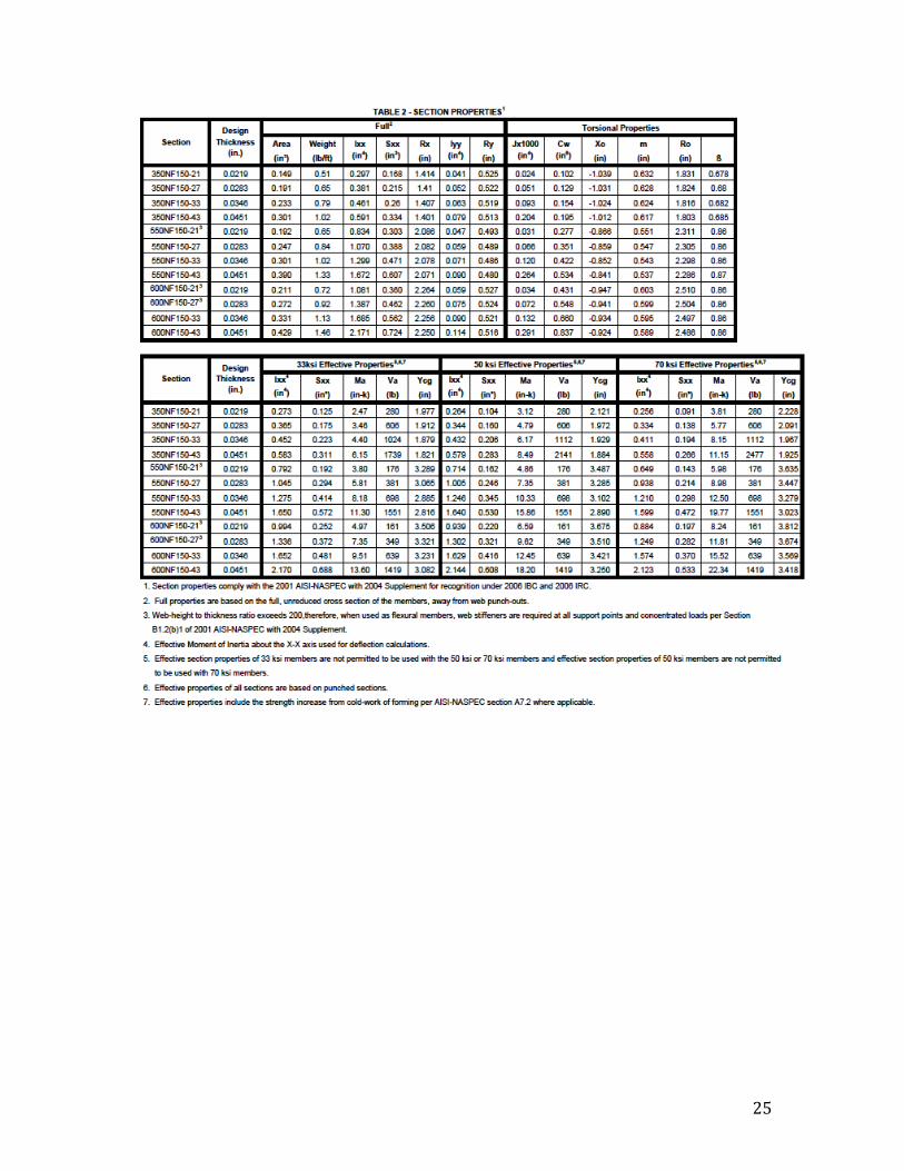
is to compete against structural steel and wood. Instead of SSMA sections, NUCON uses mostly proprietary sections. Complete dimension ranges of these sections are given in Appendix A.2. Those that are commonly found in beam-column applications are 350NF150-(21,27,33,43), 550NF150-(21,27,33,43) and 600NF150-(21,27,33,43).
!!
!!
!!
a) b) c) Figure 3 NUCON beam-column sections used in framing a) 600NF150 b) 550NF150 c)
350NF150 2.3 Metal building Metal building survey included BUTLER and MESCO. Common metal building shapes by BUTLER and MESCO are shown in Figure 4. Comprehensive sections and their properties are listed in Appendix A.3.
7
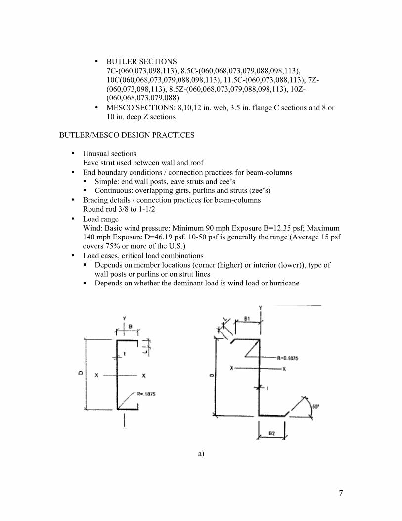
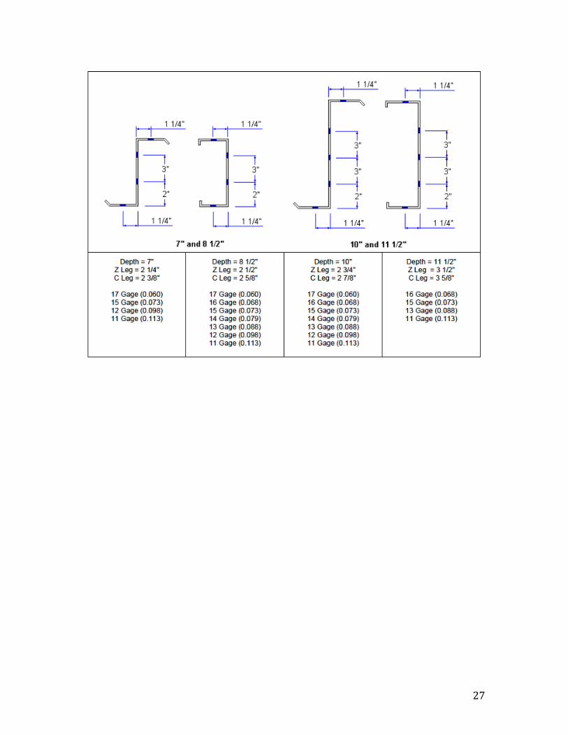
• BUTLER SECTIONS
7C-(060,073,098,113), 8.5C-(060,068,073,079,088,098,113), 10C(060,068,073,079,088,098,113), 11.5C-(060,073,088,113), 7Z-(060,073,098,113), 8.5Z-(060,068,073,079,088,098,113), 10Z-(060,068,073,079,088)
• MESCO SECTIONS: 8,10,12 in. web, 3.5 in. flange C sections and 8 or 10 in. deep Z sections
BUTLER/MESCO DESIGN PRACTICES
• Unusual sections Eave strut used between wall and roof
• End boundary conditions / connection practices for beam-columns Simple: end wall posts, eave struts and cee’s Continuous: overlapping girts, purlins and struts (zee’s)
• Bracing details / connection practices for beam-columns Round rod 3/8 to 1-1/2
• Load range Wind: Basic wind pressure: Minimum 90 mph Exposure B=12.35 psf; Maximum 140 mph Exposure D=46.19 psf. 10-50 psf is generally the range (Average 15 psf covers 75% or more of the U.S.)
• Load cases, critical load combinations Depends on member locations (corner (higher) or interior (lower)), type of
wall posts or purlins or on strut lines Depends on whether the dominant load is wind load or hurricane
a)
!
!

8
b)
Figure 4 Beam-column sections used in metal buildings a) MESCO b) BUTLER
9
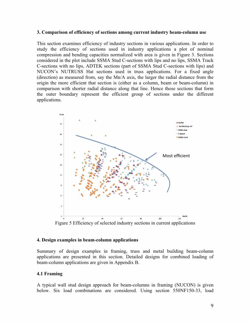
3. Comparison of efficiency of sections among current industry beam-column use This section examines efficiency of industry sections in various applications. In order to study the efficiency of sections used in industry applications a plot of nominal compression and bending capacities normalized with area is given in Figure 3. Sections considered in the plot include SSMA Stud C-sections with lips and no lips, SSMA Track C-sections with no lips, ADTEK sections (part of SSMA Stud C-sections with lips) and NUCON’s NUTRUSS Hat sections used in truss applications. For a fixed angle (direction) as measured from, say the Mn/A axis, the larger the radial distance from the origin the more efficient that section is (either as a column, beam or beam-column) in comparison with shorter radial distance along that line. Hence those sections that form the outer boundary represent the efficient group of sections under the different applications.
Most%efficient%
Pn/A%
Mn/A%
All%CFS%framing%members%
Figure 5 Efficiency of selected industry sections in current applications
4. Design examples in beam-column applications Summary of design examples in framing, truss and metal building beam-column applications are presented in this section. Detailed designs for combined loading of beam-column applications are given in Appendix B. 4.1 Framing A typical wall stud design approach for beam-columns in framing (NUCON) is given below. Six load combinations are considered. Using section 550NF150-33, load

10
combination 3 (D+W) and load combination 4 (D+0.75(Lr or S)+0.75W) result in combined interaction values of 0.86 and 0.816 respectively.

11

12
Combined loading critical member design results for CFS-NEES (DEVCO) at the first and second level framed openings are presented next. Combined interaction values observed are 1.00 and 0.90 at the second level and first level framed openings respectively. Sections used at the second level are (2) 600S162-33 back-to-back C studs; a single 600S200-68 single C stud is used at the first level. Table 1 gives a summary of framing beam-column applications (DEVCO (CFS-NEES), ADTEK and NUCON), design load combinations and traditional beam-column design interaction values.

13

14
Table 1 Summary of framing beam-column applications FRAMING Member Location Fy4(ksi) L94ft W9psf P94lb Mmax9lb.ft Pa9lb Ma9lb.ft Interaction Load4CombinationDEVCO 600S162954 Lower4level 50 9 15 3088 502 5098 1947 0.887 D+LL
600S162954 Lower4level 50 9 15 2576 536 5098 1947 0.727 D+0.75LL+0.75WADTEK 600S200954 Exterior4bearing4wall93rd4fl 50 11.5 22 4000 479.4 7093 2326.6 0.81 D+LL+W
600S250968 Exterior4bearing4wall92nd4fl 50 10.42 22 8300 393.6 10711.2 3251.2 0.92 D+LL+W600S250997 Exterior4bearing4wall91st4fl 50 10.42 22 12600 393.6 17399.1 4801.3 0.83 D+LL+W
NUCON 4550NF1509434 1st4exterior4end4wall 50 10 25.17 2383 418 3540 1068 0.89 D+0.75LL+0.75W4550NF150943 1st4exterior4wall 50 10 25.17 1840 629 3540 1068 0.92 D+0.75LL+0.75W550NF150943 2nd4exterior4wall 50 10.5 25.01 1280 689 3540 1068 0.82 D+0.75LL+0.75W4550NF150933 1st4interior4wall4 50 10 5 2329 83 2371 751 0.98 D+0.75LL+0.75W4350NF150943 1st4interior4wall4 50 10 5 2329 83 2592 588 0.9 D+0.75LL+0.75W
4.2 Truss Truss design example for an ALPINE truss is shown in Figure 6. Critical chord member #6 (section 54TSC4.00) is selected for demonstrating the beam-column design application for trusses. The combined stress indices for positive bending and negative bending are 0.81 and 0.97 respectively.
a)

15
b)
c)
Figure 6 TrusSteel truss design example a) truss b) loading case considered c) critical member

16

17
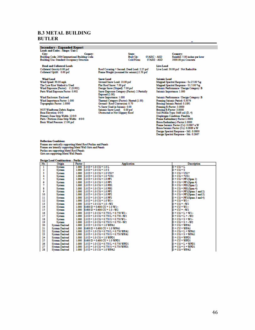
4.3 Metal building A typical CFS beam-column design example in secondary members in a metal building (BUTLER) shown in Figure 7a is presented. For the loading case shown in Figure 7b, the critical member is an 8.5in Eave strut shown in Figure 7c that sustains a combined stress ratio of 0.94. Design details can be found in Appendix B3.
a)

18
W(#1.0D+0.750L)#
P=(#f(0.750WPA2))#
#LC30=1.0D+0.750L+0.750WPA2#
b)
c) Figure 7 Butler metal building design example a) metal building b) loading case
considered c) critical member
!
19
5. Conclusions This report summarizes examples of current industry practices in cold-formed steel applications, and examines efficiency of sections used in beam-column applications. Selected critical loads are presented to aid in decision making of test matrix development. This will serve in the comparison of the new Direct Strength Method implementation with traditional beam-column design and identify critical members to investigate the potential development of an efficient beam-column direct design.

20
APPENDIX A.1 TRUSS CROSS-SECTIONS A.1.1 NUTRUSS

21
A.1.2 ALPINE/TRUSSTEEL

22

23

24
A.2 FRAMING CROSS-SECTIONS NUCON FRAMING
25

26
A.3 METAL BUILDING CROSS-SECTIONS A.3.1 BUTLER
27

28
A.3.2 MESCO
!

29
B. BEAM-COLUMN DESIGN EXAMPLES IN INDUSTRY APPLICATIONS B.1 TRUSS
!

30
!

31

32

33

34
!

35

36

37
B.2 FRAMING B.2.1 ADTEK

38

39

40

41

42
B.2.2 DEVCO

43

44

45
46
B.3 METAL BUILDING BUTLER

47

48

49

50

51

52

53