Thin Brick Veneer
12
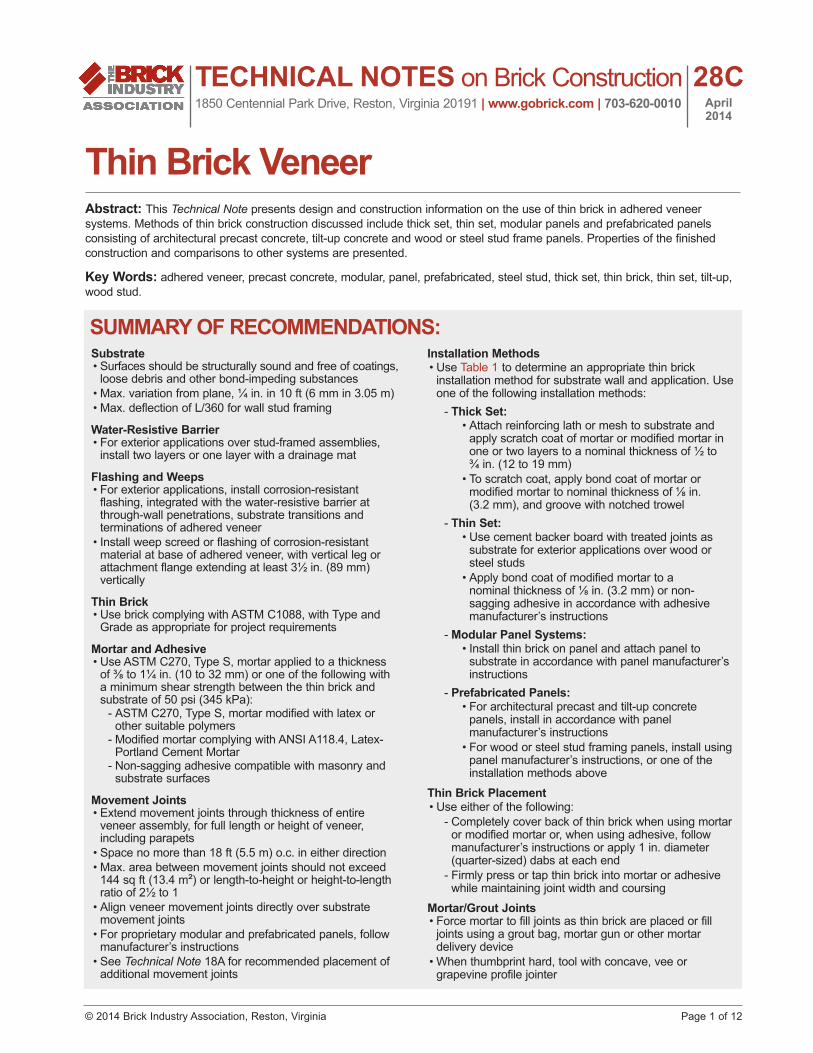
© 2014 Brick Industry Association, Reston, Virginia Page 1 of 12 TECHNICAL NOTES on Brick Construction 1850 Centennial Park Drive, Reston, Virginia 20191 | www.gobrick.com | 703-620-0010 28C April 2014 Thin Brick Veneer Abstract: This Technical Note presents design and construction information on the use of thin brick in adhered veneer systems. Methods of thin brick construction discussed include thick set, thin set, modular panels and prefabricated panels consisting of architectural precast concrete, tilt-up concrete and wood or steel stud frame panels. Properties of the finished construction and comparisons to other systems are presented. Key Words: adhered veneer, precast concrete, modular, panel, prefabricated, steel stud, thick set, thin brick, thin set, tilt-up, wood stud. Substrate • Surfaces should be structurally sound and free of coatings, loose debris and other bond-impeding substances • Max. variation from plane, ¼ in. in 10 ft (6 mm in 3.05 m) • Max. deflection of L/360 for wall stud framing Water-Resistive Barrier • For exterior applications over stud-framed assemblies, install two layers or one layer with a drainage mat Flashing and Weeps • For exterior applications, install corrosion-resistant flashing, integrated with the water-resistive barrier at through-wall penetrations, substrate transitions and terminations of adhered veneer • Install weep screed or flashing of corrosion-resistant material at base of adhered veneer, with vertical leg or attachment flange extending at least 3½ in. (89 mm) vertically Thin Brick • Use brick complying with ASTM C1088, with Type and Grade as appropriate for project requirements Mortar and Adhesive • Use ASTM C270, Type S, mortar applied to a thickness of ⅜ to 1¼ in. (10 to 32 mm) or one of the following with a minimum shear strength between the thin brick and substrate of 50 psi (345 kPa): - ASTM C270, Type S, mortar modified with latex or other suitable polymers - Modified mortar complying with ANSI A118.4, Latex- Portland Cement Mortar - Non-sagging adhesive compatible with masonry and substrate surfaces Movement Joints • Extend movement joints through thickness of entire veneer assembly, for full length or height of veneer, including parapets • Space no more than 18 ft (5.5 m) o.c. in either direction • Max. area between movement joints should not exceed 144 sq ft (13.4 m²) or length-to-height or height-to-length ratio of 2½ to 1 • Align veneer movement joints directly over substrate movement joints • For proprietary modular and prefabricated panels, follow manufacturer’s instructions • See Technical Note 18A for recommended placement of additional movement joints Installation Methods • Use Table 1 to determine an appropriate thin brick installation method for substrate wall and application. Use one of the following installation methods: - Thick Set: • Attach reinforcing lath or mesh to substrate and apply scratch coat of mortar or modified mortar in one or two layers to a nominal thickness of ½ to ¾ in. (12 to 19 mm) • To scratch coat, apply bond coat of mortar or modified mortar to nominal thickness of ⅛ in. (3.2 mm), and groove with notched trowel - Thin Set: • Use cement backer board with treated joints as substrate for exterior applications over wood or steel studs • Apply bond coat of modified mortar to a nominal thickness of ⅛ in. (3.2 mm) or non- sagging adhesive in accordance with adhesive manufacturer’s instructions - Modular Panel Systems: • Install thin brick on panel and attach panel to substrate in accordance with panel manufacturer’s instructions - Prefabricated Panels: • For architectural precast and tilt-up concrete panels, install in accordance with panel manufacturer’s instructions • For wood or steel stud framing panels, install using panel manufacturer’s instructions, or one of the installation methods above Thin Brick Placement • Use either of the following: - Completely cover back of thin brick when using mortar or modified mortar or, when using adhesive, follow manufacturer’s instructions or apply 1 in. diameter (quarter-sized) dabs at each end - Firmly press or tap thin brick into mortar or adhesive while maintaining joint width and coursing Mortar/Grout Joints • Force mortar to fill joints as thin brick are placed or fill joints using a grout bag, mortar gun or other mortar delivery device • When thumbprint hard, tool with concave, vee or grapevine profile jointer SUMMARY OF RECOMMENDATIONS:
Transcript of Thin Brick Veneer
© 2014 Brick Industry Association, Reston, Virginia Page 1 of 12
TECHNICAL NOTES on Brick Construction1850 Centennial Park Drive, Reston, Virginia 20191 | www.gobrick.com | 703-620-0010
28CApril 2014
Thin Brick VeneerAbstract: This Technical Note presents design and construction information on the use of thin brick in adhered veneer systems. Methods of thin brick construction discussed include thick set, thin set, modular panels and prefabricated panels consisting of architectural precast concrete, tilt-up concrete and wood or steel stud frame panels. Properties of the finished construction and comparisons to other systems are presented.
Key Words: adhered veneer, precast concrete, modular, panel, prefabricated, steel stud, thick set, thin brick, thin set, tilt-up, wood stud.
Substrate•Surfaces should be structurally sound and free of coatings,
loose debris and other bond-impeding substances•Max. variation from plane, ¼ in. in 10 ft (6 mm in 3.05 m)•Max. deflection of L/360 for wall stud framing
Water-Resistive Barrier •For exterior applications over stud-framed assemblies,
install two layers or one layer with a drainage mat
Flashing and Weeps •For exterior applications, install corrosion-resistant
flashing, integrated with the water-resistive barrier at through-wall penetrations, substrate transitions and terminations of adhered veneer
•Install weep screed or flashing of corrosion-resistant material at base of adhered veneer, with vertical leg or attachment flange extending at least 3½ in. (89 mm) vertically
Thin Brick•Use brick complying with ASTM C1088, with Type and
Grade as appropriate for project requirements
Mortar and Adhesive •Use ASTM C270, Type S, mortar applied to a thickness of⅜to1¼in.(10to32mm)oroneofthefollowingwitha minimum shear strength between the thin brick and substrate of 50 psi (345 kPa):
- ASTM C270, Type S, mortar modified with latex or other suitable polymers - Modified mortar complying with ANSI A118.4, Latex-Portland Cement Mortar - Non-sagging adhesive compatible with masonry and substrate surfaces
Movement Joints•Extend movement joints through thickness of entire
veneer assembly, for full length or height of veneer, including parapets
•Space no more than 18 ft (5.5 m) o.c. in either direction •Max. area between movement joints should not exceed
144 sq ft (13.4 m²) or length-to-height or height-to-length ratio of 2½ to 1
•Align veneer movement joints directly over substrate movement joints
•For proprietary modular and prefabricated panels, follow manufacturer’s instructions
•See Technical Note 18A for recommended placement of additional movement joints
Installation Methods•Use Table 1 to determine an appropriate thin brick
installation method for substrate wall and application. Use one of the following installation methods:
- Thick Set:• Attach reinforcing lath or mesh to substrate and
apply scratch coat of mortar or modified mortar in one or two layers to a nominal thickness of ½ to ¾ in. (12 to 19 mm)
•To scratch coat, apply bond coat of mortar or modifiedmortartonominalthicknessof⅛in.(3.2 mm), and groove with notched trowel
- Thin Set:•Use cement backer board with treated joints as
substrate for exterior applications over wood or steel studs
•Apply bond coat of modified mortar to a nominalthicknessof⅛in.(3.2mm)ornon-sagging adhesive in accordance with adhesive manufacturer’s instructions
- Modular Panel Systems:•Install thin brick on panel and attach panel to
substrate in accordance with panel manufacturer’s instructions
- Prefabricated Panels:•For architectural precast and tilt-up concrete
panels, install in accordance with panel manufacturer’s instructions
•For wood or steel stud framing panels, install using panel manufacturer’s instructions, or one of the installation methods above
Thin Brick Placement•Use either of the following:
- Completely cover back of thin brick when using mortar or modified mortar or, when using adhesive, follow manufacturer’s instructions or apply 1 in. diameter (quarter-sized) dabs at each end - Firmly press or tap thin brick into mortar or adhesive while maintaining joint width and coursing
Mortar/Grout Joints•Force mortar to fill joints as thin brick are placed or fill
joints using a grout bag, mortar gun or other mortar delivery device
•When thumbprint hard, tool with concave, vee or grapevine profile jointer
SUMMARY OF RECOMMENDATIONS:
www.gobrick.com | Brick Industry Association | TN 28C | Thin Brick Veneer | Page 2 of 12
INTRODUCTIONThin fired clay units, commonly known as thin brick, have gained increasing popularity by combining the aesthetic of traditional brick masonry with the economic benefits that may be realized in thinner wall sections. Though thin brick were first developed in the 1950s as a way to reface existing construction, current applications include both new and existing structures in residential and commercial construction.
Thin brick veneer, also referred to as adhered veneer, is available in many varieties but can be classified by four basic installation methods: thick set, thin set, modular panel systems and prefabricated panels. The first two involve field installation of each brick unit on a substrate with either a thick mortar bed for thick set or a thin layer of modified mortar or adhesive for thin set. Modular panel systems use an intermediary panel with a typical area of 4 to 6 sq ft (0.33 to 0.5 m²) made of polystyrene, metal or other materials to assist in supporting the thin brick. The modular panels are either fastened to the substrate wall with thin brick already adhered to them or the thin brick are adhered to the panels in the field. Prefabricated panels involve creating larger, structurally independent panels (typically) larger than 10 sq ft (1 m²) that are lifted into place on the building. Panels consisting of architectural precast concrete or steel or wood stud framing are usually constructed off-site, while concrete for tilt-up panels is usually poured in the field.
This Technical Note describes thin brick and its use in various interior and exterior adhered veneer applications. Typical installation methods, material requirements and applicable code requirements are also presented. For information on anchored brick veneer, refer to other Technical Notes in this series.
PROPERTIES OF THIN BRICK VENEERThin brick are made from the same materials and similar processes as other brick but are thinner and weigh less. Thin brick are a single element among many within an adhered veneer system that influence its characteristics. System performance can be accurately determined only when an assembly is evaluated as a whole. When compared with common light-weight cladding systems, thin brick veneer generally provides superior resistance to noise, minor impacts, abuse, heat and vandalism. The durability, fire resistance, security and acoustic comfort provided by thin brick systems are primarily due to their mass.
Adhered brick veneer can be installed where providing support for heavier, anchored brick veneer may be difficult. Thin brick systems also impart less load to buildings. Adhered thin brick veneer may be installed by masons, tilesetters or other workers. Some manufacturers can “match” thin brick with brick used in anchored veneer applications found elsewhere on the building.
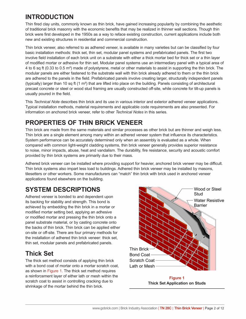
SYSTEM DESCRIPTIONSAdhered veneer is bonded to and dependent upon its backing for stability and strength. This bond is achieved by embedding the thin brick in a mortar or modified mortar setting bed, applying an adhesive or modified mortar and pressing the thin brick onto a panel substrate material, or by casting concrete onto the backs of thin brick. Thin brick can be applied either on-site or off-site. There are four primary methods for the installation of adhered thin brick veneer: thick set, thin set, modular panels and prefabricated panels.
Thick SetThe thick set method consists of applying thin brick with a bond coat of mortar onto a mortar scratch coat, as shown in Figure 1. The thick set method requires a reinforcement layer of either lath or mesh within the scratch coat to assist in controlling cracking due to shrinkage of the mortar behind the thin brick.
Figure 1Thick Set Application on Studs
Figure 1
www.gobrick.com | Brick Industry Association | TN 28C | Thin Brick Veneer | Page 3 of 12
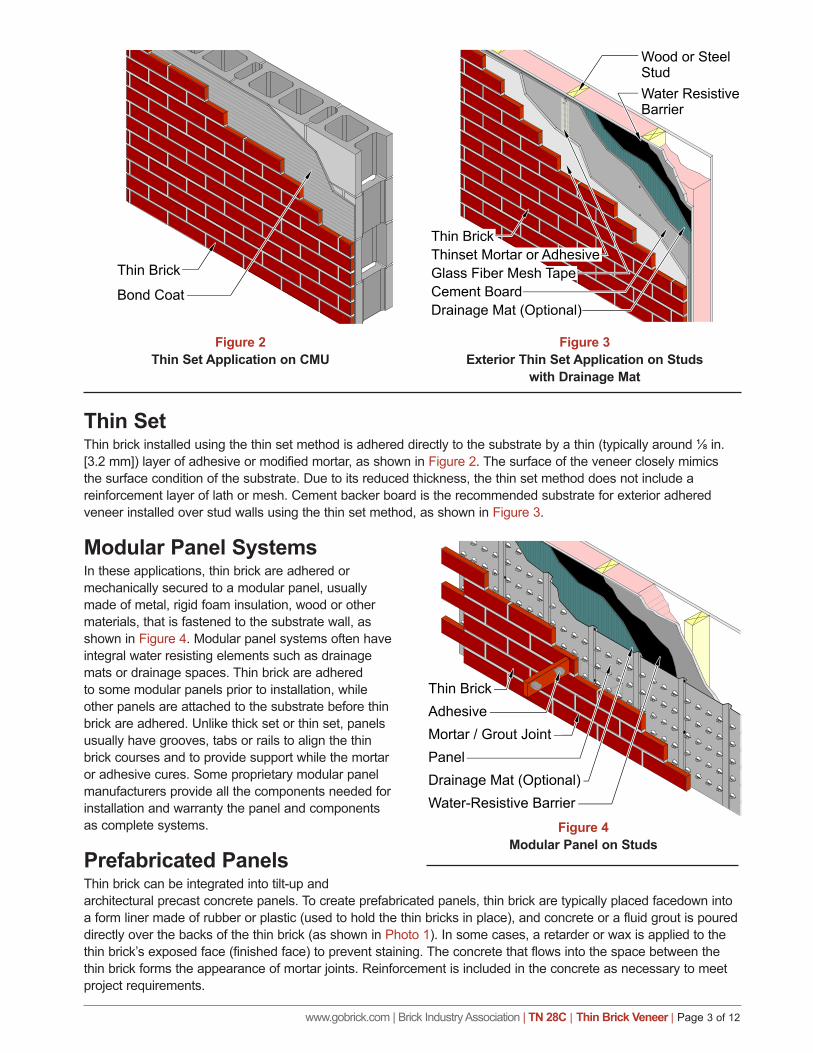
Thin SetThinbrickinstalledusingthethinsetmethodisadhereddirectlytothesubstratebyathin(typicallyaround⅛in.[3.2 mm]) layer of adhesive or modified mortar, as shown in Figure 2. The surface of the veneer closely mimics the surface condition of the substrate. Due to its reduced thickness, the thin set method does not include a reinforcement layer of lath or mesh. Cement backer board is the recommended substrate for exterior adhered veneer installed over stud walls using the thin set method, as shown in Figure 3.
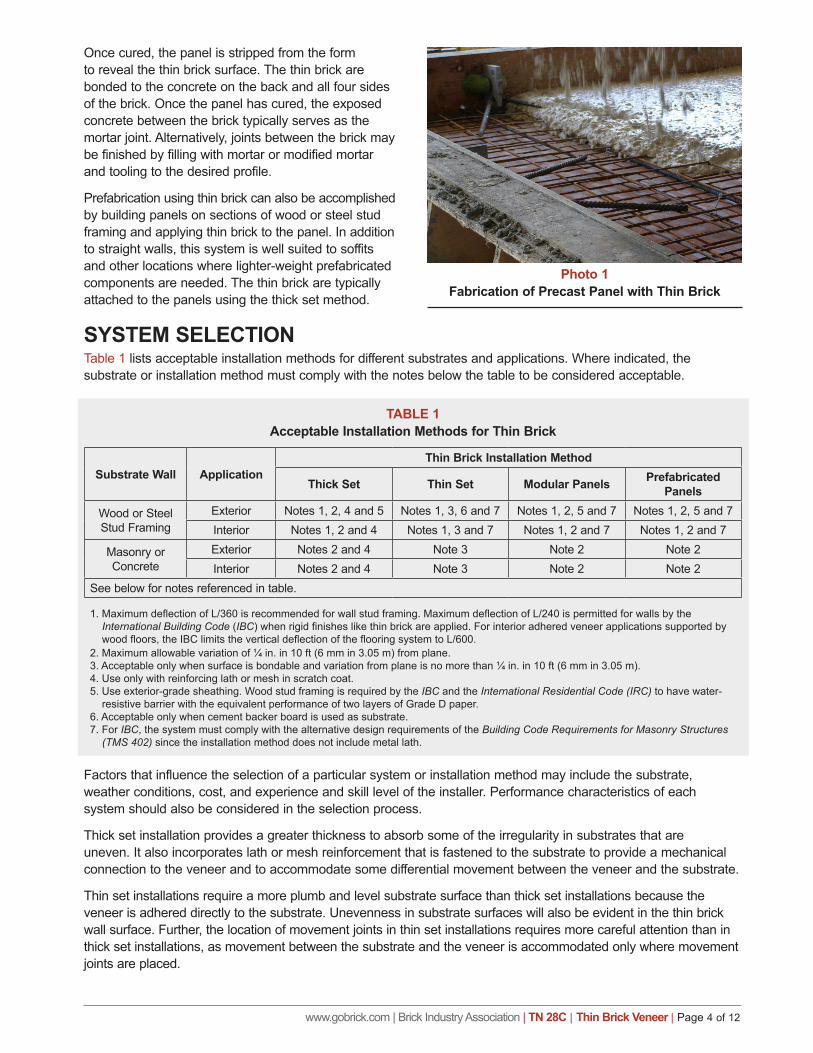
Modular Panel SystemsIn these applications, thin brick are adhered or mechanically secured to a modular panel, usually made of metal, rigid foam insulation, wood or other materials, that is fastened to the substrate wall, as shown in Figure 4. Modular panel systems often have integral water resisting elements such as drainage mats or drainage spaces. Thin brick are adhered to some modular panels prior to installation, while other panels are attached to the substrate before thin brick are adhered. Unlike thick set or thin set, panels usually have grooves, tabs or rails to align the thin brick courses and to provide support while the mortar or adhesive cures. Some proprietary modular panel manufacturers provide all the components needed for installation and warranty the panel and components as complete systems.
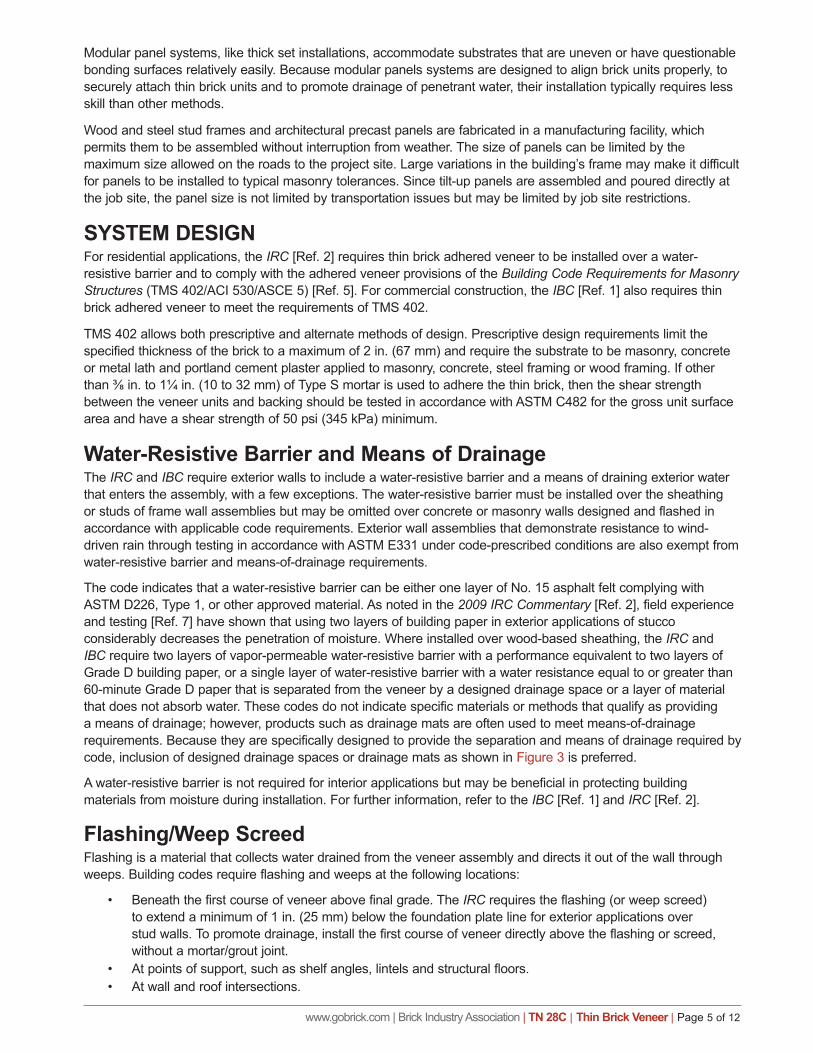
Prefabricated PanelsThin brick can be integrated into tilt-up and architectural precast concrete panels. To create prefabricated panels, thin brick are typically placed facedown into a form liner made of rubber or plastic (used to hold the thin bricks in place), and concrete or a fluid grout is poured directly over the backs of the thin brick (as shown in Photo 1). In some cases, a retarder or wax is applied to the thin brick’s exposed face (finished face) to prevent staining. The concrete that flows into the space between the thin brick forms the appearance of mortar joints. Reinforcement is included in the concrete as necessary to meet project requirements.
Figure 2Thin Set Application on CMU
Figure 3Exterior Thin Set Application on Studs
with Drainage Mat
Figure 2 Figure 3
Figure 4Modular Panel on Studs
Figure 4
www.gobrick.com | Brick Industry Association | TN 28C | Thin Brick Veneer | Page 4 of 12
Once cured, the panel is stripped from the form to reveal the thin brick surface. The thin brick are bonded to the concrete on the back and all four sides of the brick. Once the panel has cured, the exposed concrete between the brick typically serves as the mortar joint. Alternatively, joints between the brick may be finished by filling with mortar or modified mortar and tooling to the desired profile.
Prefabrication using thin brick can also be accomplished by building panels on sections of wood or steel stud framing and applying thin brick to the panel. In addition to straight walls, this system is well suited to soffits and other locations where lighter-weight prefabricated components are needed. The thin brick are typically attached to the panels using the thick set method.
SYSTEM SELECTIONTable 1 lists acceptable installation methods for different substrates and applications. Where indicated, the substrate or installation method must comply with the notes below the table to be considered acceptable.
Factors that influence the selection of a particular system or installation method may include the substrate, weather conditions, cost, and experience and skill level of the installer. Performance characteristics of each system should also be considered in the selection process.
Thick set installation provides a greater thickness to absorb some of the irregularity in substrates that are uneven. It also incorporates lath or mesh reinforcement that is fastened to the substrate to provide a mechanical connection to the veneer and to accommodate some differential movement between the veneer and the substrate.
Thin set installations require a more plumb and level substrate surface than thick set installations because the veneer is adhered directly to the substrate. Unevenness in substrate surfaces will also be evident in the thin brick wall surface. Further, the location of movement joints in thin set installations requires more careful attention than in thick set installations, as movement between the substrate and the veneer is accommodated only where movement joints are placed.
Photo 1Fabrication of Precast Panel with Thin Brick
TABLE 1Acceptable Installation Methods for Thin Brick
Substrate Wall ApplicationThin Brick Installation Method
Thick Set Thin Set Modular Panels Prefabricated Panels
Wood or Steel Stud Framing
Exterior Notes 1, 2, 4 and 5 Notes 1, 3, 6 and 7 Notes 1, 2, 5 and 7 Notes 1, 2, 5 and 7Interior Notes 1, 2 and 4 Notes 1, 3 and 7 Notes 1, 2 and 7 Notes 1, 2 and 7
Masonry or Concrete
Exterior Notes 2 and 4 Note 3 Note 2 Note 2Interior Notes 2 and 4 Note 3 Note 2 Note 2
See below for notes referenced in table.
1.MaximumdeflectionofL/360isrecommendedforwallstudframing.MaximumdeflectionofL/240ispermittedforwallsbytheInternational Building Code (IBC)whenrigidfinisheslikethinbrickareapplied.Forinterioradheredveneerapplicationssupportedbywoodfloors,theIBClimitstheverticaldeflectionoftheflooringsystemtoL/600.
2. Maximum allowable variation of ¼ in. in 10 ft (6 mm in 3.05 m) from plane.3. Acceptable only when surface is bondable and variation from plane is no more than ¼ in. in 10 ft (6 mm in 3.05 m).4. Use only with reinforcing lath or mesh in scratch coat.5. Use exterior-grade sheathing. Wood stud framing is required by the IBC and the International Residential Code (IRC) to have water-
resistive barrier with the equivalent performance of two layers of Grade D paper. 6. Acceptable only when cement backer board is used as substrate.7. For IBC, the system must comply with the alternative design requirements of the Building Code Requirements for Masonry Structures
(TMS 402) since the installation method does not include metal lath.
www.gobrick.com | Brick Industry Association | TN 28C | Thin Brick Veneer | Page 5 of 12
Modular panel systems, like thick set installations, accommodate substrates that are uneven or have questionable bonding surfaces relatively easily. Because modular panels systems are designed to align brick units properly, to securely attach thin brick units and to promote drainage of penetrant water, their installation typically requires less skill than other methods.
Wood and steel stud frames and architectural precast panels are fabricated in a manufacturing facility, which permits them to be assembled without interruption from weather. The size of panels can be limited by the maximum size allowed on the roads to the project site. Large variations in the building’s frame may make it difficult for panels to be installed to typical masonry tolerances. Since tilt-up panels are assembled and poured directly at the job site, the panel size is not limited by transportation issues but may be limited by job site restrictions.
SYSTEM DESIGNFor residential applications, the IRC [Ref. 2] requires thin brick adhered veneer to be installed over a water-resistive barrier and to comply with the adhered veneer provisions of the Building Code Requirements for Masonry Structures (TMS 402/ACI 530/ASCE 5) [Ref. 5]. For commercial construction, the IBC [Ref. 1] also requires thin brick adhered veneer to meet the requirements of TMS 402.
TMS 402 allows both prescriptive and alternate methods of design. Prescriptive design requirements limit the specified thickness of the brick to a maximum of 2 in. (67 mm) and require the substrate to be masonry, concrete or metal lath and portland cement plaster applied to masonry, concrete, steel framing or wood framing. If other than⅜in.to1¼in.(10to32mm)ofTypeSmortarisusedtoadherethethinbrick,thentheshearstrengthbetween the veneer units and backing should be tested in accordance with ASTM C482 for the gross unit surface area and have a shear strength of 50 psi (345 kPa) minimum.
Water-Resistive Barrier and Means of DrainageThe IRC and IBC require exterior walls to include a water-resistive barrier and a means of draining exterior water that enters the assembly, with a few exceptions. The water-resistive barrier must be installed over the sheathing or studs of frame wall assemblies but may be omitted over concrete or masonry walls designed and flashed in accordance with applicable code requirements. Exterior wall assemblies that demonstrate resistance to wind-driven rain through testing in accordance with ASTM E331 under code-prescribed conditions are also exempt from water-resistive barrier and means-of-drainage requirements.
The code indicates that a water-resistive barrier can be either one layer of No. 15 asphalt felt complying with ASTM D226, Type 1, or other approved material. As noted in the 2009 IRC Commentary [Ref. 2], field experience and testing [Ref. 7] have shown that using two layers of building paper in exterior applications of stucco considerably decreases the penetration of moisture. Where installed over wood-based sheathing, the IRC and IBC require two layers of vapor-permeable water-resistive barrier with a performance equivalent to two layers of Grade D building paper, or a single layer of water-resistive barrier with a water resistance equal to or greater than 60-minute Grade D paper that is separated from the veneer by a designed drainage space or a layer of material that does not absorb water. These codes do not indicate specific materials or methods that qualify as providing a means of drainage; however, products such as drainage mats are often used to meet means-of-drainage requirements. Because they are specifically designed to provide the separation and means of drainage required by code, inclusion of designed drainage spaces or drainage mats as shown in Figure 3 is preferred.
A water-resistive barrier is not required for interior applications but may be beneficial in protecting building materials from moisture during installation. For further information, refer to the IBC [Ref. 1] and IRC [Ref. 2].
Flashing/Weep ScreedFlashing is a material that collects water drained from the veneer assembly and directs it out of the wall through weeps. Building codes require flashing and weeps at the following locations:
• Beneath the first course of veneer above final grade. The IRC requires the flashing (or weep screed) to extend a minimum of 1 in. (25 mm) below the foundation plate line for exterior applications over stud walls. To promote drainage, install the first course of veneer directly above the flashing or screed, without a mortar/grout joint.
• At points of support, such as shelf angles, lintels and structural floors.• At wall and roof intersections.
www.gobrick.com | Brick Industry Association | TN 28C | Thin Brick Veneer | Page 6 of 12
• At the heads, jambs and sills of exterior window and door openings.
• At the intersection of chimneys or other masonry construction with frame or stucco walls.
• Under and at the ends of copings and sills.• Where exterior porches, decks or stairs
attach to a wall or floor assembly of wood or steel stud construction.
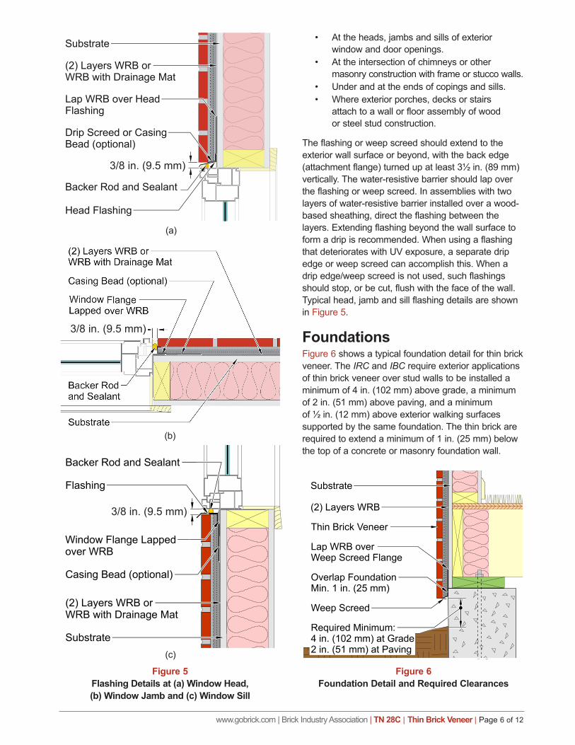
The flashing or weep screed should extend to the exterior wall surface or beyond, with the back edge (attachment flange) turned up at least 3½ in. (89 mm) vertically. The water-resistive barrier should lap over the flashing or weep screed. In assemblies with two layers of water-resistive barrier installed over a wood-based sheathing, direct the flashing between the layers. Extending flashing beyond the wall surface to form a drip is recommended. When using a flashing that deteriorates with UV exposure, a separate drip edge or weep screed can accomplish this. When a drip edge/weep screed is not used, such flashings should stop, or be cut, flush with the face of the wall. Typical head, jamb and sill flashing details are shown in Figure 5.
Foundations Figure 6 shows a typical foundation detail for thin brick veneer. The IRC and IBC require exterior applications of thin brick veneer over stud walls to be installed a minimum of 4 in. (102 mm) above grade, a minimum of 2 in. (51 mm) above paving, and a minimum of ½ in. (12 mm) above exterior walking surfaces supported by the same foundation. The thin brick are required to extend a minimum of 1 in. (25 mm) below the top of a concrete or masonry foundation wall.
Figure 5Flashing Details at (a) Window Head, (b) Window Jamb and (c) Window Sill
Figure 5
(a)
(b)
(c)
3/8 in. (9.5 mm)
3/8 in. (9.5 mm)
3/8 in. (9.5 mm)
Figure 6Foundation Detail and Required Clearances
www.gobrick.com | Brick Industry Association | TN 28C | Thin Brick Veneer | Page 7 of 12
DeflectionFor thin brick veneer with a substrate of masonry or concrete, deflection is not a concern, because the flexural stiffness of the veneer is similar to that of masonry and concrete. When the substrate wall is wood or steel stud framing, out-of-plane deflection of the framing must be considered, because the stiffness of the veneer can be substantially greater than the stud framing. The IBC limits the deflection of stud framing to a maximum of L/240 when rigid finishes like thin brick are applied. For interior adhered veneer applications supported by wood floors, the IBC limits the vertical deflection of the floor system to L/600. To decrease potential cracking and the potential for the veneer to separate from the stud framing, a wall deflection limit of L/360 is recommended when a wood or steel stud framing substrate is used.
Movement JointsThin brick veneers may experience differential movement as the brick expand and the substrate or mortar bed shrinks. To accommodate this movement, a system of movement joints should be installed through the entire layer of adhered thin brick veneer. If movement joints are not placed properly or are not used at all, cracking may occur. It is important to note that architectural precast and tilt-up concrete panels that incorporate movement joints where they are joined together usually do not require additional movement joints within the face of the panel. For movement joints of proprietary modular panel systems, follow manufacturer’s instructions. For other thin brick installation methods, incorporate movement joints at regular spacings.
Spacing. The distance between movement joints should not be more than 18 ft (5.5 m) either vertically or horizontally. Areas between movement joints should not exceed 144 sq ft (13.4 m²). Veneer areas between movement joints should preferably be square in shape but may have a maximum length-to-height or height-to-length ratio of 2½ to 1. Where thin brick veneer is adhered to a masonry or concrete substrate, the movement joints through the veneer should be installed directly over and aligned with movement joints in the substrate. Where thin brick veneer is installed on studs, the movement joints through the veneer are not necessarily required to be aligned with movement joints through the sheathing on the studs. Where lath or mesh are used, attachment should allow free movement of the veneer between movement joints.
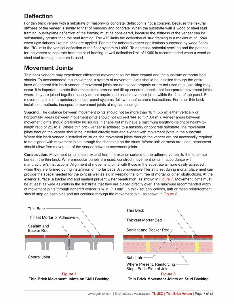
Construction. Movement joints should extend from the exterior surface of the adhered veneer to the substrate beneath the thin brick. Where modular panels are used, construct movement joints in accordance with manufacturer’s instructions. Alignment of movement joints with those in the substrate is more easily achieved when they are formed during installation of mortar beds. A compressible filler strip set during mortar placement can provide the space needed for the joint as well as aid in keeping the joint free of mortar or other obstructions. At the exterior surface, a backer rod and sealant prevent water penetration, as shown in Figure 7. Movement joints must be at least as wide as joints in the substrate that they are placed directly over. The minimum recommended width ofmovementjointsthroughadheredveneeris⅜in.(10mm).Inthicksetapplications,lathormeshreinforcementshould stop on each side and not continue through the movement joint, as shown in Figure 8.
Figure 7Thin Brick Movement Joints on CMU Backing
Figure 8Thin Brick Movement Joints on Stud Backing
www.gobrick.com | Brick Industry Association | TN 28C | Thin Brick Veneer | Page 8 of 12
Continuous InsulationIn order to meet prescriptive thermal performance requirements found within various energy codes, continuous insulation is increasingly incorporated into adhered veneer systems. Adhered veneer may be installed over continuous insulation; however, longer, more robust fasteners capable of carrying the weight of the veneer unsupported through the thickness of the insulation will typically require design by an engineer. “Guide to Attaching Exterior Wall Coverings through Foam Sheathing to Wood or Steel Wall Framing” [Ref. 6], published by the Foam Sheathing Committee of The American Chemistry Council, provides a directed approach that may assist engineers in designing adequate connections through continuous insulation.
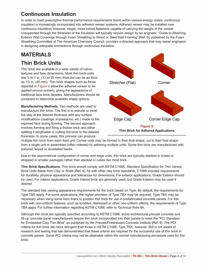
MATERIALS Thin Brick UnitsThin brick are available in a wide variety of colors, textures and face dimensions. Most thin brick units are ½ to 1 in. (13 to 25 mm) thick but can be as thick as 1¾ in. (45 mm). Thin brick shapes such as those depicted in Figure 9 allow the adhered veneer to be applied around corners, giving the appearance of traditional face brick facades. Manufacturers should be contacted to determine available shape options.
Manufacturing Methods. Two methods are used to manufacture thin brick. The first is to extrude or mold the clay at the desired thickness with any surface modifications (coatings, impressions, etc.) made to the exposed face during forming. The second approach involves forming and firing a thicker brick and either splitting it lengthwise or cutting the brick to the desired thickness. In some cases, this process can produce multiple thin brick from each fired unit. Corner units may be formed in their final shape, cut to their final shape from a single unit or assembled (often mitered) by adhering multiple units. Some thin brick are manufactured with textured, keyed or dovetailed backs.
Due to the asymmetrical configuration of corner and edge units, thin brick are typically stacked in boxes or strapped in smaller packages rather than stacked in cubes like most brick.
Thin Brick Specifications. Thin brick should comply with ASTM C1088, Standard Specification for Thin Veneer Brick Units Made from Clay or Shale [Ref. 4]. As with other clay brick standards, C1088 includes requirements for durability, physical appearance and tolerances for dimensions. For exterior applications, Grade Exterior should be used. For interior applications, Grade Interior brick are generally used, but Grade Exterior may be used if desired.
The standard has varying appearance requirements for the brick based on Type. By default, the requirements for Type TBS apply. For some applications, the higher precision of Type TBX may be required. Type TBX may be necessary when using some form liners to position thin brick for use in prefabricated concrete panels. For thin brick with non-uniform features, such as tumbled, distressed or other non-uniform effects, the requirements of Type TBA apply. For further information regarding ASTM C1088, refer to Technical Note 9A.
Although thin brick are typically specified according to ASTM C1088, some architectural precast concrete and tilt-up concrete panel manufacturers require thin brick incorporated into their panels to meet the “PCI Standard for Embedded Clay Thin Brick” as published by the Precast/Prestressed Concrete Institute [Ref. 8]. The PCI criteria for thin brick are more stringent than those in ASTM C1088, Type TBX; however, BIA is not aware of research and testing that has demonstrated that these criteria are required for the successful use of thin brick in concrete panels. Some PCI criteria may not be attainable within the normal manufacturing processes used for thin brick.
Figure 9Thin Brick for Adhered Applications
www.gobrick.com | Brick Industry Association | TN 28C | Thin Brick Veneer | Page 9 of 12
Reinforcing Lath and MeshReinforcing lath and mesh should be made of corrosion-resistant materials. Galvanized or stainless steel are most common; however other materials such as glass fiber lath may be acceptable with a product evaluation approval. Metallathshouldbeeither2.5lb/sqyd(1.4kg/m²)or⅜in.(10mm)rib,3.4lb/sqyd(1.8kg/m²)metallathcomplying with ASTM C847. Self-furred lath or lath attached with self-furring fasteners is recommended. Woven wire mesh should be minimum 18 gauge complying with ASTM C1032. Glass fiber lath should comply with applicable building code requirements. Glass fiber lath is not recommended for applications over open stud framing.
MortarMortar and modified mortar used for scratch and bond coats should comply with ASTM C270, Specification for Mortar for Unit Masonry, Type S, with or without a latex or polymer modifier specifically designed for use with thin veneer; or with ANSI 118.4. Mortar used to fill joints may have a higher water content as required by installation method. For more information on mortar, refer to Technical Note 8.
Modified mortar. Typically a modified mortar is a portland cement mortar modified by adding a polymer/latex additive or a bond enhancer. Latex additives may improve adhesion, reduce water absorption and provide greater bond strength and resistance to shock and impact. When using the liquid form of latex, it is added as a replacement for part or all of the water used when mixing the mortar.
Flashing Many materials are suitable for use as flashing in adhered veneer walls. Flashing materials should be corrosion-resistant, waterproof, durable and sufficiently tough and flexible so as to resist puncture and cracking. Flashing should also be compatible with other materials in the veneer assembly, such as adhesives and sealants. Technical Note 7A discusses characteristics of some common flashing materials. The use of superior materials reduces the potential for system failure and exceedingly expensive costs associated with replacement.
Weep screeds or flashing used at the base of the wall must be a minimum 0.019 in. (0.48 mm) or 26-gage galvanized or plastic with a minimum vertical attachment flange of 3½ in. (89 mm). Asphalt-impregnated felt, building paper and house/building wraps are not acceptable for use as flashing.
Cement (Backer) BoardCement (backer) board, which consists of a cementitious binder reinforced by fiber mats, is a dimensionally stable substrate for decorative finishes in wet or dry areas. Cement board used as a substrate for exterior wall applications of thin brick should be at least ½ in. (13 mm) thick and conform to ASTM C1325, Type A, or ANSI 118.9.
INSTALLATIONThe following sections provide recommended procedures for installing thin brick via the thick set and thin set methods and describe the installation of modular and prefabricated panels. Installation of mortar in thin brick veneer applications should be scheduled when temperatures will be between 40 °F (4 °C) and 90 °F (32 °C). Otherwise, cold or hot weather construction measures, as described in Technical Note 1, should be employed.
Installation methods for ceramic tile, as published by the Tile Council of North America in the TCNA Handbook for Ceramic, Glass, and Stone Tile Installation [Ref. 3], may also be used to install thin brick in thick set and thin set applications. For thick set with a masonry or concrete substrate, use Method W201. For thin set with a masonry or concrete substrate, apply according to Method W202. For thick set with stud framing, use Method W222. For interior applications of thin set on stud framing, use Method W243.
Substrate and Surface Preparation Where thin brick units are installed on site, proper construction and preparation of the substrate to receive them is critical. Surfaces receiving thin brick should be structurally sound and free of loose or deleterious debris or residue, including algae, mold, dust, laitance, paste, wallpaper or laminate. Remove all substances that could potentially impede the bonding of the veneer. Such substances include oils, greases, waxes, bond-release agents, sealers, solvents, paints or other coatings or surface preparations. If a substrate surface is wet, then the water source must be identified and eliminated. Surfaces on which thin brick are placed must not vary from plane by more than ¼ in. in 10 ft (6 mm in 3.05 m). Taping sheathing joints or fastening sheathing edges with plywood clips can sometimes

www.gobrick.com | Brick Industry Association | TN 28C | Thin Brick Veneer | Page 10 of 12
reduce unevenness. If a surface does not comply with surface tolerances, then a leveling coat must be applied before proceeding.
Walls of wood and steel stud framing should be designed to meet lateral deflection requirements. Exterior walls of wood or steel stud framing require a water-resistive barrier on sheathing. Fasten cement board through sheathing and water-resistive barrier into studs. Joints of cement board should be staggered and offset from sheathing joints. Treat cement board joints with alkali-resistant glass fiber mesh tape embedded in mortar or modified mortar in accordance with cement board manufacturer recommendations. Allow masonry and concrete substrates to cure for 28 days prior to installation of thin brick veneer.
Thick Set MethodMetal lath or wire mesh should be applied over the water-resistive barrier and attached with 11 gauge nails 1½ in. (38 mm) in length with a 7⁄16in.(11mm)heador16gaugestaples⅞in.(22mm)inlength,spacedataminimumof6 in. (152 mm) o.c. Lap the lath or mesh a minimum of 2 in. (51 mm) at sides and ends where sheets are joined. Lap mesh one full mesh, wire to wire, where joined.
Attach lath or mesh to wood stud framing with corrosion-resistant fasteners that penetrate a minimum of 1 in. (25 mm) into the stud. For steel stud framing, use corrosion-resistant screws that extend through the steel stud connection a minimum of three exposed threads. For masonry or concrete, use hardened concrete nails or powder-actuated fasteners that penetrate a minimum of 1 in. (25 mm).
Scratch Coat. For thick set systems, a scratch coat of mortar with a nominal thickness of ½ to ¾ in. (12 to 19 mm) is applied to the lath or mesh until it is fully embedded in the mortar. The scratch coat can be applied in one layer orastwonominal¼to⅜in.(6to10mm)layers,wherethefirstlayerfullyembedsthelathormesh.Thesurfaceof each layer should be scratched (scored) horizontally when thumbprint hard and allowed to cure before applying the next layer or coat. Installation in a single layer may be preferable during periods of hot or cold weather to avoid potential delamination between layers.
Bond Coat. Apply a bond coat of mortar or modified mortar over a damp scratch coat to a nominal thickness of ⅛in.(3.2mm)andgroovewithasquare-notchedtrowel.Formaximumadhesion,coveringtheentirebackofthethin brick with bond coat mortar is recommended. While the coat remains wet and workable, embed the thin brick into the bond coat and fill mortar joints as described in the “Setting Thin Brick” and “Mortar Joints” sections below.
Thin Set MethodAn adhesive or modified mortar may be used to bond thin brick to the substrate in thin set applications.
Adhesive. Thin brick may be adhered with a non-sagging adhesive compatible with the thin brick and substrate. These are typically available in tubes and are applied using a pressure gun. Apply the adhesive according to manufacturer’s instructions. The adhesive is usually applied in 1 in. diameter (quarter-sized) dabs on the back of the brick at each end. Adhesives should not be applied in a manner that will trap water, resulting in subsequent freezing and thawing. Figure 10 shows an interior application of thin brick on wood stud framing using the thin set method.
Modified Mortar. Dry components of modified mortar should be pre-blended prior to adding the latex additive. Apply according to manufacturer’s instructions. Most manufacturersrecommendanominal⅛in.(3.2mm)thickness.Formaximumadhesion,completecoverageoftheback of thin brick with bond coat mortar is advised. Apply modified mortar over an area no greater than can be covered by thin brick while the mortar remains workable. Use a notched trowel as recommended by the mortar manufacturer toevenlyspreadthemodifiedmortartoanominal⅛in.(3.2mm)thickness.Within10minutesofapplyingthelatex-modified mortar on the substrate, completely cover the back of thin brick with modified mortar and embed in substrate mortar coat as indicated in the “Setting Thin Brick” section below.
Figure 10Interior Thin Set Application on Studs
www.gobrick.com | Brick Industry Association | TN 28C | Thin Brick Veneer | Page 11 of 12
Setting Thin BrickEach thin brick should be firmly pressed or tapped into place, taking care to maintain proper spacing and alignment of the joints and bond pattern. Setting each brick with a rubber mallet or a beating block can help to ensure flatness and secure bedding. If mortar or modified mortar is used, a slight excess should squeeze out of the joints between brick during the setting process. Once the thin brick is set, it should not be moved or the bond may be compromised. If a thin brick is inadvertently moved after initial set has begun, it should be removed, along with any bond coat behind it, and a new thin brick unit installed with fresh mortar, modified mortar or adhesive. Proper setting of each thin brick is critical to ensuring a durable thin brick system. Improper setting of the thin brick is the most frequent cause of poor performance.
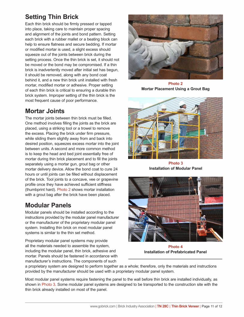
Mortar JointsThe mortar joints between thin brick must be filled. One method involves filling the joints as the brick are placed, using a striking tool or a trowel to remove the excess. Placing the brick under firm pressure, while sliding them slightly away from and back into desired position, squeezes excess mortar into the joint between units. A second and more common method is to keep the head and bed joint essentially free of mortar during thin brick placement and to fill the joints separately using a mortar gun, grout bag or other mortar delivery device. Allow the bond coat to cure 24 hours or until joints can be filled without displacement of the brick. Tool joints to a concave, vee or grapevine profile once they have achieved sufficient stiffness (thumbprint hard). Photo 2 shows mortar installation with a grout bag after the brick have been placed.
Modular PanelsModular panels should be installed according to the instructions provided by the modular panel manufacturer or the manufacturer of the proprietary modular panel system. Installing thin brick on most modular panel systems is similar to the thin set method.
Proprietary modular panel systems may provide all the materials needed to assemble the system, including the modular panel, thin brick, adhesive and mortar. Panels should be fastened in accordance with manufacturer’s instructions. The components of such a proprietary system are designed to perform together as a whole; therefore, only the materials and instructions provided by the manufacturer should be used with a proprietary modular panel system.
Most modular panel systems require fastening the panel to the wall before thin brick are installed individually, as shown in Photo 3. Some modular panel systems are designed to be transported to the construction site with the thin brick already installed on most of the panel.
Photo 2Mortar Placement Using a Grout Bag
Photo 3Installation of Modular Panel
Photo 4Installation of Prefabricated Panel
www.gobrick.com | Brick Industry Association | TN 28C | Thin Brick Veneer | Page 12 of 12
Prefabricated PanelsBrick-faced precast concrete panels and prefabricated wood and steel wall panels are typically attached using anchorage devices embedded in the concrete to the building structural frame or foundation. The panels are typically delivered to the job site by truck and lifted into place using a crane or a hoist, as shown in Photo 4. Panels are adjusted to be level, plumb and in alignment with adjacent façade elements before they are bolted or welded in place.
MAINTENANCEIf properly designed, detailed and constructed, minimal maintenance is required for thin brick applications. Brick veneer should be inspected periodically to ascertain performance and to identify any potential problems. Inspections are recommended on an annual basis at a minimum. Such inspections should address sealant joints, any loose units, plumbness of the wall, cracking, etc., to identify repairs and corrections before severe issues develop. For additional information regarding maintenance, refer to Technical Note 46.
SUMMARYThin brick can be installed over a variety of substrates in both exterior and interior applications using thick set, thin set, modular panels or prefabricated panels. This Technical Note describes thin brick systems currently in use and includes recommendations on the selection, design, materials and installation of each system.
The information and suggestions contained in this Technical Note are based on the available data and the experience of the engineering staff and members of the Brick Industry Association. The information contained herein must be used in conjunction with good technical judgment and a basic understanding of the properties of brick masonry. Final decisions on the use of the informa-tion discussed in this Technical Note are not within the purview of the Brick Industry Association and must rest with the project architect, engineer and owner.
REFERENCES 1. 2012 International Building Code, International Code Council, Inc., Country Club Hills, IL, 2012.
2. 2012 International Residential Code and Commentary, International Code Council, Inc., Country Club Hills, IL, 2012.
3. 2013 TCNA Handbook for Ceramic Tile Installation, 50th Anniversary Edition, Tile Council of North America, Inc., Anderson, SC, 2013.
4. ASTM International, Annual Book of ASTM Standards, West Conshohocken, PA, 2013.
Vol 4.01 ASTM C847, Standard Specification for Metal Lath ASTM C1032, Standard Specification for Woven Wire Plaster Base
Vol. 4.05 ASTM C270, Standard Specification for Mortar for Unit Masonry ASTM C1088, Standard Specification for Thin Veneer Brick Units Made From Clay or Shale ASTM C1325, Standard Specification for Non-Asbestos FIber-Mat Reinforced Cementitious Backer Units
5. Building Code Requirements for Masonry Structures (TMS 402-13/ACI 530-13/ASCE 5-13), The Masonry Society, Boulder, CO, 2013.
6. FSC Tech Matters, “Guide to Attaching Exterior Wall Coverings through Foam Sheathing to Wood or Steel Wall Framing,” Foam Sheathing Coalition (of the American Chemistry Council), Washington, DC, December 4, 2012, http://fsc.americanchemistry.com/Building-Code/Installation-of-Cladding/Guide-to-Attaching-Exterior-Wall-Coverings.pdf
7. Leslie, Neil P., “Residential Stucco Wall Assembly Moisture Performance Evaluation,” ASHRAE Transactions, Vol. 114, Part 1, New York, NY 2008.
8. PCI Standard for Embedded Clay Thin Brick, Precast/Prestressed Concrete Institute, Chicago, IL, 2013.