ThermoTile Installation Guidelines - 2 ThermoTile® Installation Guidelines Radiant Floor Heating...
24
Rev.28.1.8.16 - 1 ThermoTile® Radiant Floor Heating Mat with inside. Installation Guidelines Congratulations on your purchase of revolutionary ThermoTile® heating mats -- the simplest way to enjoy the luxury of safe, soothing, warm floors. Easy to install. Takes the cold chill off tile and other hard surface floors. Brings soothing warmth to specific rooms or cold areas. Complements your home heating system making rooms more comfortable . Reduces energy up to 40% compared to forced air heating. Can be used as a sole room heating source.* Does not circulate pollutants, dust, dirt, allergens or dry air. Maintenance free, strong, durable and water proof. Special double coating resists scratching, abrasion and corrosion. Suitable for most floor coverings when imbedded in mortar. Zero EMF (electromagnetic field). ThermoTile heating mats are available in 120 and 240 Volt in these sizes: Volts Mat Model W x L Coverage S.F. Watts/ S.F. Amps 120 TT 5 - 120 1.5’ x 5’ 7.5 12 0.8 120 TT 7 - 120 1.5’ x 7’ 10.5 12 1.1 120 TT10 -120 1.5’ x 10’ 15 12 1.5 120 TT15 -120 1.5’ x 15’ 22.5 12 2.3 120 TT20 -120 1.5’ x 20’ 30 12 3.0 120 TT30 -120 1.5’ x 30’ 45 12 4.5 120 TT40 -120 1.5’ x 40’ 60 12 6.0 120 TT50 -120 1.5 x 50’ 75 12 7.5 120 TT60 -120 1.5’ x 60’ 90 12 9.0 120 TT70 -120 1.5’ x 70’ 105 12 10.5 240 TT10 -240 1.5’ x 10’ 15 12 0.8 240 TT14 -240 1.5’ x 14’ 21 12 1.1 240 TT20 -240 1.5’ x 20’ 30 12 1.5 240 TT30- 240 1.5’ x 30’ 45 12 2.3 240 TT40 -240 1.5’ x 40’ 60 12 3.0 240 TT60 -240 1.5’ x 60’ 90 12 4.5 240 TT80 -240 1.5’ x 80’ 120 12 6.0 240 TT100-240 1.5’ x 100’ 150 12 7.5 240 TT120-240 1.5’ x 120’ 180 12 9.0 *To use ThermoTile as the sole room heating source, make sure your BTU requirements are met by the total Watts of ThermoTile installed. 1,000 Watts = 3,413 BTU’s/hour. ThermoSoft International Corp. • 701 Corporate Woods Parkway • Vernon Hills, IL 60061 • 847-279-3800 Conforms to UL Safety Standard 758 ® Conforms to UL Safety Standard 1693 CAN/CSA C22.2 Zero Electromagnetic Field Conforms to European Standards
Transcript of ThermoTile Installation Guidelines - 2 ThermoTile® Installation Guidelines Radiant Floor Heating...

Rev.28.1.8.16 - 1
ThermoTile®
Radiant Floor Heating Mat with inside.
Installation Guidelines
Congratulations on your purchase of revolutionary ThermoTile® heating mats -- the
simplest way to enjoy the luxury of safe, soothing, warm floors.
Easy to install.
Takes the cold chill off tile and other hard surface floors.
Brings soothing warmth to specific rooms or cold areas.
Complements your home heating system making rooms more comfortable .
Reduces energy up to 40% compared to forced air heating.
Can be used as a sole room heating source.*
Does not circulate pollutants, dust, dirt, allergens or dry air.
Maintenance free, strong, durable and water proof.
Special double coating resists scratching, abrasion and corrosion.
Suitable for most floor coverings when imbedded in mortar.
Zero EMF (electromagnetic field).
ThermoTile heating mats are available in 120 and 240 Volt in these sizes:
Volts Mat Model W x L Coverage S.F. Watts/
S.F. Amps
120 TT 5 - 120 1.5’ x 5’ 7.5 12 0.8
120 TT 7 - 120 1.5’ x 7’ 10.5 12 1.1
120 TT10 -120 1.5’ x 10’ 15 12 1.5
120 TT15 -120 1.5’ x 15’ 22.5 12 2.3
120 TT20 -120 1.5’ x 20’ 30 12 3.0
120 TT30 -120 1.5’ x 30’ 45 12 4.5
120 TT40 -120 1.5’ x 40’ 60 12 6.0
120 TT50 -120 1.5 x 50’ 75 12 7.5 120 TT60 -120 1.5’ x 60’ 90 12 9.0
120 TT70 -120 1.5’ x 70’ 105 12 10.5
240 TT10 -240 1.5’ x 10’ 15 12 0.8
240 TT14 -240 1.5’ x 14’ 21 12 1.1
240 TT20 -240 1.5’ x 20’ 30 12 1.5
240 TT30- 240 1.5’ x 30’ 45 12 2.3
240 TT40 -240 1.5’ x 40’ 60 12 3.0
240 TT60 -240 1.5’ x 60’ 90 12 4.5
240 TT80 -240 1.5’ x 80’ 120 12 6.0
240 TT100-240 1.5’ x 100’ 150 12 7.5
240 TT120-240 1.5’ x 120’ 180 12 9.0 *To use ThermoTile as the sole room heating source, make sure your BTU requirements
are met by the total Watts of ThermoTile installed. 1,000 Watts = 3,413 BTU’s/hour.
ThermoSoft International Corp. • 701 Corporate Woods Parkway • Vernon Hills, IL 60061 • 847-279-3800
Conforms to UL
Safety Standard 758
®
Conforms to UL Safety Standard 1693
CAN/CSA C22.2
Zero Electromagnetic Field
Conforms to European
Standards

Rev.28.1.8.16 - 2
ThermoTile® Installation Guidelines
Radiant Floor Heating Mat
Cautions
THIS EQUIPMENT SHALL BE INSTALLED ONLY BY QUALIFIED PERSONNEL WHO ARE FAMILIAR WITH THE CONSTRUCTION AND OPERATION OF THE APPARATUS AND THE RISKS INVOLVED.
THE INSTALLATION OF THIS HEATING PRODUCT SHALL BE IN ACCORDANCE WITH THE MANUFACTURER’S INSTRUCTIONS AND LOCAL AND NATIONAL CODES.
IN CANADA,THE INSTALLATION SHALL BE MADE ACCORDING TO THE PROVISIONS OF SECTION 62 OF THE CANADIAN ELECTRICAL CODE, PART 1.
WARNING - as described in these instructions, lead wires are not to be routed over pads or come into contact with the heating elements as DAMAGE TO SUPPLY CONDUCTOR INSULATION MAY OCCUR IF CONDUCTORS ARE ROUTED to contact heating elements. REFER TO INSTALLATION INSTRUCTIONS FOR RECOMMENDED MEANS OF ROUTING SUPPLY CONDUCTORS.
THE TYPE AND THICKNESS OF FLOOR COVERING MATERIALS USED WITH THIS PRODUCT MUST NOT EXCEED A THERMAL INSULATION “R” VALUE OF 1.0. EXAMPLE “R” VALUES: CARPET ¼” THICK = R 1.0 CERAMIC, MOSAIC TILE .25” THICK = R0.15 LAMINATE FLOORING = R 0.675 PLYWOOD 0.5” THICK = R 0.63 NATURAL STONE (GRANITE, LIMESTONE, MARBLE, SANDSTONE) 1” THICK = 0.38-0.114 WOOD FLOORING = R 0.80 MAXIMUM
DO NOT OVERLAP HEATING WIRES OR ALLOW HEATING WIRES TO CROSS-OVER.
CAUTION: USE COPPER ONLY AS SUPPLY CONDUCTORS
THERE ARE NO SPECIAL CRIMPING TOOLS REQUIRED FOR THIS PRODUCT.
ATTENTION: CONIFIER L’INSTALLATION DE CE MATERIEL AUN PERSONNEL QUALIFIE, QUI CONNAIT BIEN L’APPAREIL ET LES RISQUES INHERENTS.
CE SYSTEME DE PANNEAUX CHAUFFANTE DOIT ETRE INSTALLECONFORMEMENT AUX EXIGENCES DE TOUS LES POUVOIRS DE REGLEMENTATION.
ATTENTION: UTILISER DES CONDUCTEURS EN CUIVRE SEULEMENT.

Rev.28.1.8.16 - 3
ThermoTile® Installation Guidelines
Radiant Floor Heating Mat
Overview
There are four main sections to installing ThermoTile heating mats:
Electrical installation..........................Section 1
ThermoTile Installation.....................Section 2
Floor Covering Installation................ Section 3
Final wiring and connections.............Section 4
Where moisture may be present, it is recommended that the circuit have a GFCI
(ground fault circuit interrupter) installed*. Never energize the mat rolled up!
Control Switch
There are several control switch options in both 120V and 240V versions.
1. For the most economical installation in terms of up-front cost, a simple variable control (dimmer) switch can be installed. Make sure that the switch is capable of handling the total number of Watts generated by the mats that will be connected to the switch. To determine total Watts of the mats, add the Watts for each mat or multiply 12 Watts per S.F. by the total number of S.F. represented by the mats. Since dimmer switches do not cycle on and off like thermostats to maintain the temperature, the ongoing operating cost could be higher with a dimmer switch than with a thermostat.
2. To achieve more precise temperature regulation, and a more economical operating cost, a thermostat can be installed with a floor sensor under your floor. The thermostat will automatically cycle on and off to maintain the set temperature.
3. To achieve maximum energy savings, a programmable thermostat with floor sensor can be installed. The programmable thermostat can be programmed to go to different temperature levels or on and off at different times of the day.
Make sure that the Amperage rating of the thermostat or other control switch is not
exceeded by the total Amps of the ThermoTile mats being installed.
*Our programmable thermostat includes a 5 mA GFCI. The lower the mA number, the
more sensitive the GFCI is to ground fault detection and tripping. The 5mA GFCI is recommended for wet area installations such as in baths and kitchens where moisture may be present.

Rev.28.1.8.16 - 4
Sec.1. Electrical Installation
Ground fault circuit interrupter (GFCI) – (Over-current Protection)
1. A ground fault circuit interrupter (GFCI) is recommended for bath and kitchen or any
installations where moisture may be present.
Note: Follow all local building and electrical codes.
It is possible to branch from an existing circuit if the Amps provided by the circuit
are sufficient to supply the Amp load of the ThermoTile® floor heating mats
and all the other appliances that are or will be connected to the circuit. If the
Amp supply is not sufficient, install a dedicated circuit. Consult with a qualified
electrician to determine if the circuit can handle the load.
The size of the circuit is determined by the total Amp load of the heating mats. You
may need multiple circuit breakers, multiple thermostats or a contactor/relay for
installations larger than 15 Amps. See the chart on page 1 for determining the Amps
drawn by each ThermoTile mat. Total Amps for all of the mats installed must not
exceed the circuit Amperage or the 15 Amp limit of the thermostat.
Install Electrical Boxes
2. Plan the location of the electrical box for the thermostat. Each ThermoTile mat has 10’
lead wires. Place the electrical box within reach of the lead wires or cut the fiberglass
mesh and extend the heating wire along the floor until the cold lead reaches the box.
Do not extend the heating wire up into the wall. Alternatively, junction all leads at a
junction box and extend appropriate conductor in the wall to the thermostat box.
3. For the programmable thermostat, install a 1-gang (2” wide) or 2-gang (4” wide)
electrical box with 1-gang mud ring. Note: the 4” box provides more room to work with
multiple lead wires. If using our manual (MTC style) thermostat, install a 2.25” or 4”
electrical box. Electrical boxes are typically located 4-5’ from the floor for readability.
The heating mat lead wires can be connected in a junction box with appropriate
conductor wire to the thermostat electric box.
4. The floor sensor wire can be extended up to 50’ if necessary by splicing comparable 20
gauge, multi-stranded, insulated, electrical wire and waterproofing the splice.
Bottom Plate Work
Drill or saw holes at the bottom plate (See Fig 2.) One hole is for routing the power leads

Rev.28.1.8.16 - 5
and the other hole is for routing the thermostat sensor wire. These holes should be directly
below the electrical box.
5. Remove one of the knock-outs in the electrical box to route the lead wires.
6. If required by code to install conduit, install ½” minimum conduit from the bottom plate
up to the electrical box. Install ¾” conduit if necessary to make room for more lead
wires when using multiple ThermoTile® heating mats. See Figure 2. Attach the
conduit to the electrical box with an appropriate locknut. Close the bottom end of the
conduit flush with the wall and fit with insulated bushing to prevent chafing of wire on
exposed edge.
7. A thermostat control comes with a floor sensor wire. Do not install the floor sensor wire
in the same conduit as the lead wires. Install the floor sensor wire in a separate
conduit or simply attach it to the stud with appropriate fasteners. Be careful not to cut
or penetrate the sensor wire. Suggestion: install a 3/8” plastic or copper tube from
the electric box going down the wall and under the floor for sliding the sensor
wire in and out should it ever become necessary to replace the sensor. Check
the resistance of the sensor wire to be sure it is near 14.8 kOhms at 68°F or 12.0
kOhms at 77°F. (See page 22 “Measuring Resistance”). If installing a redundant
sensor, install the probe end under the floor and leave the other end inside the
thermostat box but do not connect it. Only one floor sensor should be connected
to the thermostat.
8. Open a second knock-out in the bottom of the electrical box. Feed the sensor wire
through the knock-out down through the cut-out in the bottom plate, and out into the
floor area where the ThermoTile heating mat will be installed.
Wiring
9. Install appropriate electrical wire (conductor) from the power source following all codes.
Leave extra wire at the control switch/thermostat box for making connections.
10. Refer to the Typical Wiring Diagrams (FIG. 3.1 and 3.2) at the end of these installation
guidelines.
Installing a Relay (Contactor)
11. Depending on the Amperage requirements of multiple ThermoTile heating mats, a
contactor / relay may be required. Consult with an electrician to determine the type and
size of contactor / relay required, or contact Thermosoft technical support for
suggestions.
Rev.28.1.8.16 - 6
Sec. 2. ThermoTile® Installation
Planning
Plan the heated area of the floor so that the desired area of the floor can be heated with
a combination of the available mat sizes. When planning your heated floor area, keep
the following important points in mind:
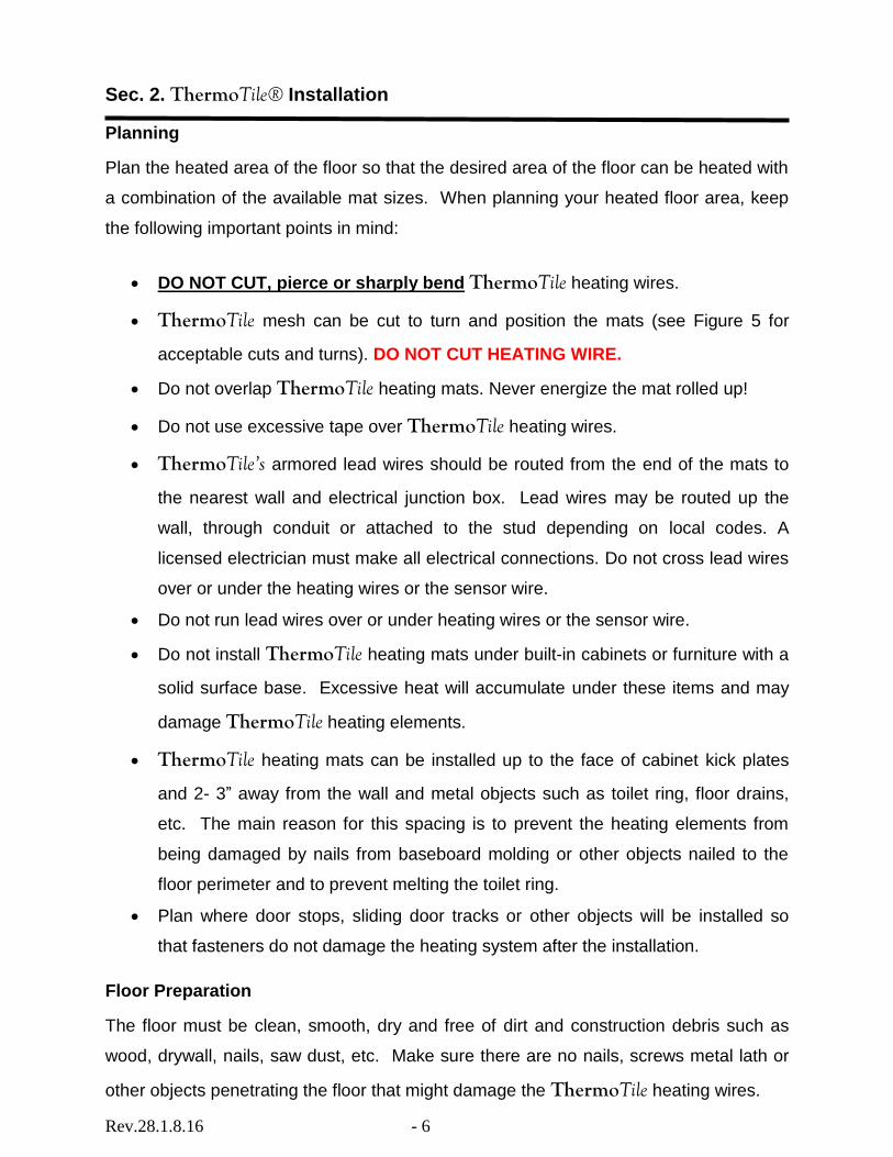
DO NOT CUT, pierce or sharply bend ThermoTile heating wires.
ThermoTile mesh can be cut to turn and position the mats (see Figure 5 for
acceptable cuts and turns). DO NOT CUT HEATING WIRE.
Do not overlap ThermoTile heating mats. Never energize the mat rolled up!
Do not use excessive tape over ThermoTile heating wires.
ThermoTile’s armored lead wires should be routed from the end of the mats to
the nearest wall and electrical junction box. Lead wires may be routed up the
wall, through conduit or attached to the stud depending on local codes. A
licensed electrician must make all electrical connections. Do not cross lead wires
over or under the heating wires or the sensor wire.
Do not run lead wires over or under heating wires or the sensor wire.
Do not install ThermoTile heating mats under built-in cabinets or furniture with a
solid surface base. Excessive heat will accumulate under these items and may
damage ThermoTile heating elements.
ThermoTile heating mats can be installed up to the face of cabinet kick plates
and 2- 3” away from the wall and metal objects such as toilet ring, floor drains,
etc. The main reason for this spacing is to prevent the heating elements from
being damaged by nails from baseboard molding or other objects nailed to the
floor perimeter and to prevent melting the toilet ring.
Plan where door stops, sliding door tracks or other objects will be installed so
that fasteners do not damage the heating system after the installation.
Floor Preparation
The floor must be clean, smooth, dry and free of dirt and construction debris such as
wood, drywall, nails, saw dust, etc. Make sure there are no nails, screws metal lath or
other objects penetrating the floor that might damage the ThermoTile heating wires.

Rev.28.1.8.16 - 7
Important Notes:
Install ThermoTile® before applying the final thin-set layer or self-leveling mortar.
For best results, we recommend:
1. Use latex, acrylic or polymer modified Portland cement (thin-set) mortar for laying tiles . 2. Use a latex, acrylic or epoxy grout for grouting between the tiles. Epoxy grouts
provide high strength, good thermal shock resistance and fast cure.
ThermoTile Preparation
1. Remove the ThermoTile heating mats from the box. Attach both lead wires (120V:
black & white; 240V black & red) to a high quality digital ohmmeter to measure the
resistance. Compare the resistance you measured to the resistance recorded by the
factory on the label attached to the mat. Also measure the resistance between
each heating wire and the ground wire. If the resistance is not within ±10% of the
factory recorded resistance, or if there is a resistance value between either
heating wire and ground, call our customer service number for assistance.
Damage may have occurred during shipping. Do not proceed with the installation.
Keep a record of resistance measures as they will be needed for warranty purposes
(see Sec. 5) and (see page 22 “Measuring Resistance”).
2. Leave the factory labels attached to the lead wires for later inspection. Save
warning label #1, it must be placed near or on the face of the control (see Section 4,
Step #4.)
Layout
3. Lay ThermoTile heating mats on the subfloor. Leave at least 3” of space between
the ThermoTile mats and the wall, metal objects such as tub and floor drains, 4-6”
from the toilet ring. It is OK to place ThermoTile up to the edge of counter and
cabinet kick plates. Heat will radiate 1.5” from the edge of the mat. See fig. 5 for
how to manipulate & turn mats.
4. Lay out lead wires so they run to the nearest wall where the electrical box is located.
See Fig. 1. Electrical connections to the thermostat will be made later.
5. Allow at least 2-3” of floor space between the wall and ThermoTile to run the
armored lead wire. 3” of the armored lead wire must be buried under thin-set

Rev.28.1.8.16 - 8
mortar. Do not stress or bend the lead wire splice connection. Use duct tape or hot
glue to hold lead wires in place – DO NOT STAPLE over any wires. Chisel a groove
in the floor if necessary to lower the armored lead wire or sensor probe.
6. ThermoTile® mats should be completely flat, do not overlap the mat. There should
always be a space between heating wires of 2-3 inches. When turning mats,
stagger the loops somewhat to maintain spacing.
7. Attach (using staples, double-sided tape, hot glue or thin strips of duct tape) the
heating mat to the sub-floor or slab to hold it in place. See Fig.1. Do not staple over
ThermoTile heating wires. Thin (1/4”-1/2”) strips of tape (similar to the tape holding
the wires to the mat) or hot glue can be used to tape down the heating wire loops if
necessary. (Note: mats will float up with self-leveling cement if not adhered to floor).
8. The thermostat sensor wire should be routed from the thermostat electric box to the
floor and extended at least 6-12 inches in to the ThermoTile heating mat (see Fig.
4). Position the sensor probe equally spaced between two ThermoTile heating
wires. Weave the sensor wire between the mesh to hold it in place.
9. Before installing your floor (Section 3), use the ohmmeter to record the resistance
measurement of the ThermoTile heating mat (see p. 22 “Measuring Resistance). If
the resistance is more than ±10% of the factory recorded resistance or if there is any
resistance between the heating wires and ground, call our customer service number
for assistance. Damage may have occurred during installation. Do not proceed with
the installation. Keep a record of resistance measures (Section 5) for warranty.
10. Be careful to always protect the ThermoTile heating wires or sensor probe during
the installation process. Minimize walking on mats. Cover with cardboard or
plywood to protect.
Make sure there are no nails or screws penetrating the floor that could damage
the ThermoTile heating wires.
Check the resistance of the sensor wire to be sure it is near 14.8 kOhms at
68°F or 12.0 kOhms at 77°F.
11. DO NOT ATTEMPT TO CONNECT THE MATS IN SERIES (ONE TO ANOTHER).
The mats must be connected in parallel in a junction box or at the thermostat box – see
Sec 4. Final Wiring and Connections.
Rev.28.1.8.16 - 9
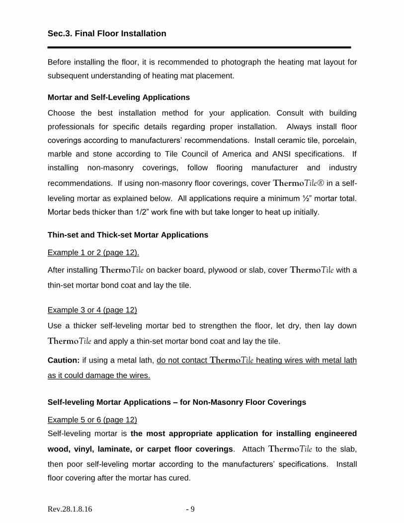
Sec.3. Final Floor Installation
Before installing the floor, it is recommended to photograph the heating mat layout for
subsequent understanding of heating mat placement.
Mortar and Self-Leveling Applications
Choose the best installation method for your application. Consult with building
professionals for specific details regarding proper installation. Always install floor
coverings according to manufacturers’ recommendations. Install ceramic tile, porcelain,
marble and stone according to Tile Council of America and ANSI specifications. If
installing non-masonry coverings, follow flooring manufacturer and industry
recommendations. If using non-masonry floor coverings, cover ThermoTile® in a self-
leveling mortar as explained below. All applications require a minimum ½” mortar total.
Mortar beds thicker than 1/2” work fine with but take longer to heat up initially.
Thin-set and Thick-set Mortar Applications
Example 1 or 2 (page 12).
After installing ThermoTile on backer board, plywood or slab, cover ThermoTile with a
thin-set mortar bond coat and lay the tile.
Example 3 or 4 (page 12)
Use a thicker self-leveling mortar bed to strengthen the floor, let dry, then lay down
ThermoTile and apply a thin-set mortar bond coat and lay the tile.
Caution: if using a metal lath, do not contact ThermoTile heating wires with metal lath
as it could damage the wires.
Self-leveling Mortar Applications – for Non-Masonry Floor Coverings
Example 5 or 6 (page 12)
Self-leveling mortar is the most appropriate application for installing engineered
wood, vinyl, laminate, or carpet floor coverings. Attach ThermoTile to the slab,
then poor self-leveling mortar according to the manufacturers’ specifications. Install
floor covering after the mortar has cured.

Rev.28.1.8.16 - 10
Special Precautions:
Isolation Membrane: Install ThermoTile® above the membrane unless recommended
otherwise by the membrane manufacturer.
Insulation: Do not install rigid insulation directly above or below backer board or mortar.
Mosaic Tile: Embed ThermoTile in a thin mortar bed (1/4”-3/8”), then thin-set the
mosaic tile according to typical practice (total thin-set not less than ½”).
Expansion Joints: Do not install heating mats through an expansion joint. Install mats
right up to but not through the expansion.
Sub-floor Insulation: If possible, install insulation as shown in the diagrams on page 12.
Insulation enhances performance and efficiency.
Trowel Size:
Select a proper size trowel for the installation of tile or stone. We recommended using a
square or “U” notch trowel with notch size appropriate for the size and type of tile
installed (minimum 1/4”x3/8”x1/4”). This trowel works best for most ¼” tile. A plastic
trowel is ideal for minimizing the risk of abrasion of the heating wires.
Mortar & Grout
Latex or acrylic modified Portland cement mortar (thin-set) and
acrylic grout is recommended to minimize grout cracking later on.
WARNING: Do not bang trowel on the ThermoTile mat or heating wire. This could
cut the heating wire. When cleaning excess thin-set mortar from between tiles
before grouting, do not use sharp objects or go deep enough to cut the heating
elements below. Contact customer service for tile removal suggestions.
SUGGESTION: To avoid installation damage to heating wires, float a thin 3/16”-
1/4” layer of thin set or apply 3/16” self-leveling cement and let dry. Test working
mats by energizing for one minute. In a second step, lay tile with notched trowel
as normal. If troweling directly over ThermoTile, we recommend using our plastic
3/8” notched trowel that minimizes nicking the heating wires.

Rev.28.1.8.16 - 11
Install Floor Covering
SUGGESTION: Throughout the floor installation, connect mats to an Ohmeter or
continuity meter with an alarm that will sound if continuity is broken (if the wire is
cut or damaged causing a short). This will alert you to the need for repair or
replacement before finishing the floor covering installation. It is also a good idea
to power up and test the system for one minute prior to installing the final floor
covering to verify the wires heat up and the GFCI does not trip. See section 4 for
wiring connections.
DISCONNECT POWER BEFORE INSTALLING FINAL FLOOR COVERING.
Follow industry or manufacturers’ recommendations.
For tile or stone, we recommend following the Tile Council of America guidelines and
ANSI specifications as minimum standards for installation as long as floor covering R
value does not exceed 1 and total thin-set applied is not less than ½”.
All floor coverings must be in direct contact with the cement-based material that covers
ThermoTile®. Do not elevate the floor above the mortar. Do not use furring strips
(sleepers) between mats unless leveled-off with self-leveling cement as described on
page 9. Air gaps can cause a reduction in heating effectiveness.
Final Resistance Measure
After installing your floor, use the ohmmeter to record the final resistance measurement
of the ThermoTile heating mat (see page 22 “Measuring Resistance”). If the resistance
is more than ±10% of the factory recorded resistance or if there is any resistance
between the heating wires and ground, call our customer service number for assistance.
Damage may have occurred during floor installation. Keep a record of all three
resistance measures as they will be needed for warranty purposes (see Section 5).

Rev.28.1.8.16 - 12
Example 1 Thin-set Mortar over Framed Floor (dry –set or latex cement mortar TCA#F144-2k)
Example 2 Thin-Set Mortar over Slab (dry –set or latex cement on slab TCA#F113-2k)
Example 3 Thick-set Cement Mortar Metal Lath set (cement mortar metal lath TCA#145-2k)
Example 4 Thick-set Mortar Bed over Slab (Cement Mortar Bonded TCA#F112-2k)
Example 5 Self-Leveling Mortar over Frame Floor (carpet, vinyl, laminate)
Example 6 Self-Leveling Mortar over Slab on Grade (carpet, vinyl, laminate)
Tile, stone Latex-Portland cement mortar bond coat ThermoTile® Backer board Mortar bed Plywood
Insulation
Tile, stone Latex-Portland cement mortar bond coat ThermoTile Slab
Insulation (if allowed)
Tile, stone or laminate Latex-Portland cement mortar bond coat ThermoTile Mortar bond coat Metal Lath
Plywood
Insulation
Tile, stone or laminate Latex-Portland cement mortar bond coat ThermoTile Mortar bed Mortar Bond Coat, crack isolation membrane or cork underlayment. Slab Insulation (per International Residential
Code, chapter 11).
Self-leveling mortar bed ThermoTile Plywood
Insulation (per International Residential Code, chapter 11).
Self-leveling mortar bed
ThermoTile Crack isolation membrane or cork underlayment. Concrete slab with rewire or rebar Insulation (per International Residential Code, chapter 11).

Rev.28.1.8.16 - 13
Shower Installation:
Installation shall be made in accordance with the National Electric Code, NFPA-70. Final acceptance is to be made by the Authority Having Jurisdiction (AHJ).
ThermoTile is manufactured to be waterproof and may be installed in shower
applications by following all the installation instructions in this manual, the additional instructions listed below and all local and national electric codes. It is highly recommended to connect InstAlarm® during the installation to warn about accidental damage to the heating or lead wires.
1. A separate ThermoTile mat may be started in the shower or continued from the main
bath floor by rolling the mat up, over and down the shower curb or by using heating wire free-of-mesh to transition from the floor up, over and down the curb. Similarly, free-wire can be used to transition up to the shower seat for heating the top of the seat. Maintain a soft turning radius when flexing the wire while making these transitions to insure that the heating wire is not severely creased at a 90 degree angle. 2. Never make a field splice or repair to any section of the mat installed in a shower; serious hazard could result.
3. Completely embed ThermoTile mats and lead wire including connection in minimum
½” thick thin-set mortar with no air gaps. 4. Install a water-proof membrane above the heating mat following the membrane manufacturer’s instructions. Membranes should add negligible R-value. 5. Check mat resistance at all intervals during the installation as explained elsewhere in these guidelines. (See page 22 “Measuring Resistance”). 6. Install ceramic tile, marble, porcelain, stone or other masonry surface. 7. The thermostat or other control must be located at least 4’ away from shower openings so the thermostat or control is not exposed to water or within reach of a person taking a shower. 8. Connect the mats to a Class A (5mA GFCI) thermostat (or separate Class A GFCI in the circuit).

Rev.28.1.8.16 - 14
Sec. 4. Final Wiring and Connections
CAUTION: ELECTRICAL CIRCUIT POWER MUST BE TURNED OFF
1. Install the thermostat in the electrical box according to the installation instructions
provided with the thermostat. Connect the power mat leads, floor sensor, and
power supply wiring as shown in the instructions that came with and are
diagramed on the back of the thermostat. Reference Figure 3 for general wiring
diagrams.
2. Route ThermoTile® lead wires to a junction box or to the thermostat or control
switch electric box. Connect the heating mats together and to the thermostat by
wiring the heating mat lead wires in parallel (not series) as follows: white-to-
white (neutral), black-to-black (line) and ground-to-ground (bare metal wires);
NOTE: 240V wires are black and red. Connect ground wires to the power source
ground or if using the MTC style thermostat to the terminal marked PE. The total
Amp load of ThermoTile mats must not exceed the thermostat’s 15 Amp limit or
the Amperage rating of the circuit or other control switch without using an
appropriately rated contactor / relay - see Fig. 3.1 (120V circuit) or Fig. 3.2 (240V
circuit).
3. Use the appropriate size cover ring to mount the thermostat to the electrical box.
4. Indicate which branch circuits supply the ThermoTile heating mat and retain the
UL labels for each ThermoTile mat in a convenient location, i.e., taped to the
circuit breaker box, for reference by the electrical inspector or homeowner.
Leave one UL label attached to the ThermoTile mat. Attach the warning label in
a convenient location to show the room location where ThermoTile is installed.
5. After all controls are installed, power up the system briefly to test operation of all
components.
6. Refer to instructions provided with the controls for proper setting. Keep
instructions in a safe place for future reference.

Rev.28.1.8.16 - 15
Sec. 5. Resistance Measures
For each ThermoTile® mat, use this convenient worksheet to record resistance
measures. Retain this record for warranty purposes. (See page 22 “Measuring Resistance”).
Factory Information
(From UL label)
Resistance
Measure 1
(Out of the box)
Resistance
Measure #2
(After laying
ThermoTile)
Resistance
Measure #3
(After laying floor
covering)
Serial number__________________
Mat Size______________________
Volts_________________________
Factory Resistance_________Ohms
____________
(Ohms)
____________
(Ohms)
____________
(Ohms)
Serial number__________________
Mat Size______________________
Volts_________________________
Factory Resistance_________Ohms
____________
(Ohms)
____________
(Ohms)
____________
(Ohms)
Serial number__________________
Mat Size______________________
Volts_________________________
Factory Resistance_________Ohms
____________
(Ohms)
____________
(Ohms)
____________
(Ohms)
Serial number__________________
Mat Size______________________
Volts_________________________
Factory Resistance_________Ohms
____________
(Ohms)
____________
(Ohms)
____________
(Ohms)
Serial number__________________
Mat Size______________________
Volts_________________________
Factory Resistance_________Ohms
____________
(Ohms)
____________
(Ohms)
____________
(Ohms)
√ No resistance
between heating wires/ground.
√ No resistance
between heating wires/ground.
√ No resistance
between heating wires/ground.
√ No resistance
between heating wires/ground.
√ No resistance
between heating wires/ground.
√ No resistance
between heating wires/ground.
√ No resistance
between heating wires/ground.
√ No resistance
between heating wires/ground.
√ No resistance
between heating wires/ground.
√ No resistance
between heating wires/ground.
√ No resistance
between heating wires/ground.
√ No resistance
between heating wires/ground.
√ No resistance
between heating wires/ground.
√ No resistance
between heating wires/ground.
√ No resistance
between heating wires/ground.

Rev.28.1.8.16 - 16
ThermoTile® Installation Guidelines
ThermoTile TT20-120
ThermoTile TT40-120
10’ row
U-turn creates 1.5”
natural spacing
between heating wire
loops in parallel rows
from the same mat.
U-turn
10’ row
10’ row
10’ row
Sensor**
*contactor/relay if required
Lead wires
thermostat
conduit for lead wires if required.
Leave 2-3” space from the wall to run lead wires or excess heating wire. Note: bury at least 3” of the armored lead wire under the thin-set mortar. Avoid stressing the splice point – do not bend splice. * A thermostat power module or relay (contactor) may be required for large installations. Consult Thermosoft technical support or an electrician. ** Sensor can be run down the wall stud or in a separate conduit from the power leads.
Figure 1
Shown: 2 ThermoTile mats: TT40-120 and TT20-120 with U-Turn cuts creating 6 10’ rows.
U-turn
2-3” between mat loops
from separate mats
Rev.28.1.8.16 - 17
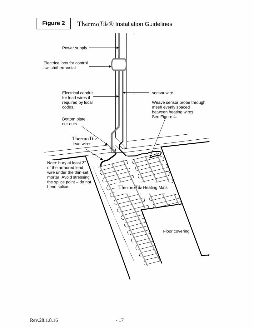
Figure 2
Electrical box for control switch/thermostat
Power supply
Electrical conduit for lead wires if required by local codes.
sensor wire. Weave sensor probe through mesh evenly spaced between heating wires. See Figure 4.
Bottom plate cut-outs
ThermoTile® Installation Guidelines
ThermoTile lead wires
Note: bury at least 3” of the armored lead wire under the thin-set mortar. Avoid stressing the splice point – do not bend splice.
Floor covering
ThermoTile Heating Mats

Rev.28.1.8.16 - 18
ThermoTile® Installation Guidelines
Control Wiring Diagrams
Typical Electrical Wiring Diagram w/thermostat control (120V)
Typical Electrical Wiring Diagram w/contactor & thermostat control (120V)
•
Load - Black
Mat - Black
Load - White
Mat - White 120V
Control (back)
Floor Sensor Wire (no polarity)
•
•
• 120VAC
ThermoTile Heating Mat
Control - Black
Control - White
•
•
Line - Black
Neutral – White
Sensor Probe
Ground - Green Mat – bare wire
All electrical work must be done by a qualified, licensed electrician in accordance with local building and electrical codes, and the National Electrical Code (NEC), especially Article 424, Part IX of the NEC, ANSI/NFPA 70 and Section 62 of CEC Part I.
120V Control (back)
Floor Sensor Wire (no polarity)
• • Control - Black
Control - White
• •
Line - Black
Neutral–White
Contactor (120V Coil)
• • • •
Mat – Black
Mat - White
Sensor Probe
•
•
Load – Black
Load – White
120VAC
ThermoTile Heating Mat
Ground - Green Mat – Bare wire
All electrical work must be done by a qualified, licensed electrician in accordance with local building and electrical codes, and the National Electrical Code (NEC), especially Article 424, Part IX of the NEC, ANSI/NFPA 70 and Section 62 of CEC Part I.
Figure 3.1
• •
• •
120VAC Circuit
Breaker
120VAC Circuit
Breaker
***Refer to Instructions that came with your specific thermostat***

Rev.28.1.8.16 - 19
ThermoTile® Installation Guidelines
Control Wiring Diagrams
Typical Electrical Wiring Diagram w/thermostat control (240V)
Typical Electrical Wiring Diagram w/contactor & thermostat control (240V)
•
Load - Black
Mat - Black
Load - Red
Mat - Red 240V
Control (back)
Floor Sensor Wire (no polarity)
•
•
• Control - Black
Control – Red
•
•
Line - Black
Line – Red
Sensor Probe
Ground - Green Mat – bare wire
240VAC
ThermoTile Heating Mat
240VAC Circuit
Breaker
All electrical work must be done by a qualified, licensed electrician in accordance with local building and electrical codes, and the National Electrical Code (NEC), especially Article 424, Part IX of the NEC, ANSI/NFPA 70 and Section 62 of CEC Part I.
240V Control (back)
Floor Sensor Wire (no polarity)
• • Control - Black
Control - Red
• •
Line - Black
Line – Red
Contactor (240V Coil)
• • • •
Mat – Black
Mat - Red
Sensor Probe
•
•
Load – Black
Load – Red
240VAC
ThermoTile Heating Mat
Ground - Green Mat – bare wire
All electrical work must be done by a qualified, licensed electrician in accordance with local building and electrical codes, and the National Electrical Code (NEC), especially Article 424, Part IX of the NEC, ANSI/NFPA 70 and Section 62 of CEC Part I.
Figure 3.2
• •
• •
240VAC Circuit
Breaker
***Refer to Instructions that came with your specific thermostat***

Rev.28.1.8.16 - 20
ThermoTile® Installation Guidelines
Sensor Wire Location
Sensor wire
Heating wire ThermoTile heating mat
Tape
Locate thermostat sensor probe equally spaced between two heating wires and weave over and under the mesh to keep sensor wire in place while tiling.
Sensor probe
Figure 4

Rev.28.1.8.16 - 21
Figure 5 ThermoTile® Installation Guidelines
Mat Cuts & Turns
Fill Turn

Rev.28.1.8.16 - 22
Measuring Resistance
Insert probes into multimeter marked VΩmA and COM. Color of probe does not matter.
Set multimeter to section marked with the Ohm symbol: Ω and 200 Ohms or if the heating mat has resistance over 200 Ohms, then set the multi-meter to 2000 (see circle).
Note: when measuring the resistance of the thermostat floor sensor, set the meter to 20K.
Wrap black and white lead wires from 120V mats (or black and red lead wires from 240V mats) around the multimeter probes (color of probe does not matter).
Avoid touching the probes during measurement as it could affect the accuracy of the resistance value.
Record the resistance value displayed by the multimeter, in this example 143.6.
Compare the resistance measurement with the value recorded on the factory label, in this case 142.8. If the difference is within ±10%, the resistance of the mat is OK.
In this case, the difference is 0.6% calculated as follows: (143.6-142.8) / 142.8 x 100.
Measure the resistance between each wire and the ground wire. There should be an open circuit or infinite resistance between the heating wires and the ground wire.
Infinite resistance is displayed by the multimeter as 1 on the left side of the display or as .OL on other multimeters.

Rev.28.1.8.16 - 23
ThermoTile® LIFETIME LIMITED WARRANTY RADIANT FLOOR HEATING MAT
Thermosoft International Corporation (“Manufacturer”) warrants that its ThermoTile radiant floor heating mat (“Product”) is free from defects in manufacturing, materials and workmanship in manufacture and will perform under normal use for as long as the homeowner owns the home where ThermoTile was installed (“Limited Warranty Period”). Manufacturer is not responsible for damage to mats caused on the job. This warranty shall not be valid under the following conditions: 1) The preparation, conditions and installation of the Product is not in accordance with industry standards, Manufacturer’s installation guidelines, floor covering manufacturers’ installation guidelines, the Tile Council of America for ceramic, porcelain and natural stone applications, The National Electric Code (NEC), the Canadian Electric Code (CEC) and all applicable local electrical and building codes 2) the lateral sub-floor crack exceeds one-quarter inch (1/4 inch); 3) the installation is not conducted as per Manufacturer’s written instructions; 4) the sub-floor is not within tolerances of vapor emissions per industry standards; 5) defective materials such as mortar, tile, grout, or adhesive are used in the installation; 6) vertical cracking, settling or displacement occurs; 7) there exists a failure of floor patching or leveling materials, or use of non-approved patching or leveling materials; or 8) improper installation materials or methods are used, 9) local overheating is caused by use not in accordance with Manufacturer’s instructions, 10) the Product is not connected to the power source by a licensed electrician, 11) the owner fails to retain and supply resistance measurements recorded during installation as specified by the Manufacturer’s instructions 12) the Product’s heating elements are cut, punctured or tampered with. This limited warranty is extended to the original owner of the property where the Product is installed (the “Owner”) and does not cover damage to the floor or floor covering. This Limited Lifetime Warranty is further subject to the exclusions and limitations provided below and on the reverse side.
TO OBTAIN WARRANTY SERVICE, FOLLOW THE INSTRUCTIONS IN STEP 4 BELOW. UPON RECEIPT OF THE DEFECTIVE PRODUCT, PAPERWORK, RECEIPT AND RESISTANCE MEASURES, MANUFACTURER WILL EXAMINE AND TEST THE PRODUCT. IF IT IS DETERMINED THAT THE PRODUCT WAS PROPERLY INSTALLED AND FAILED DURING NORMAL USE AS A RESULT OF A MANUFACTURING, DEFECT, , THE MANUFACTURER WILL REMEDY THE DEFECT OR FAILURE WITHOUT CHARGE TO THE OWNER PROVIDED MANUFACTURER RECEIVES NOTICE OF THE WARRANTY CLAIM IN THE MANNER PROVIDED BELOW WITHIN THE LIMITED WARRANTY PERIOD. THE REMEDY FOR ANY SUCH DEFECT IS LIMITED, AT MANUFACTURER’S OPTION, TO THE REPAIR, REPLACEMENT, OR REFUND OF THE PURCHASE PRICE OF THE PRODUCT. THE WARRANTY PERIOD FOR THE REPLACEMENT PRODUCT WILL EXPIRE WHEN THE OWNER SELLS THE HOME. THIS LIMITED WARRANTY DOES NOT APPLY TO THE THERMOSTATIC CONTROL UNIT WHICH IS A SEPARATELY PURCHASED COMPONENT THAT CARRIES ITS OWN WARRANTY. CONTROLS SOLD UNDER THE THERMOSOFT NAME ARE WARRANTED FOR ONE YEAR. MANUFACTURER WARRANTS THAT THE PRODUCT PRODUCES THE RATED WATT OUTPUT LISTED ON THE PRODUCT LABEL WHEN OPERATED AT THE RATED VOLTAGE. MANUFACTURER MAKES NO REPRESENTATION CONCERNING THE TEMPERATURE LEVEL THAT WILL BE PRODUCED BY THE PRODUCT. MANUFACTURER ASSUMES NO LIABILITY FOR THE COST OF FLOOR COVERING MATERIALS OR THE COST TO REMOVE OR REPLACE THEM. IMPORTANT: FOR THIS WARRANTY TO BE VALID, THIS PRODUCT MUST BE CONNECTED TO THE ELECTRICAL SOURCE AND PROPERLY GROUNDED ACCORDING TO THE INSTRUCTIONS BY A LICENSED ELECTRICIAN.
THIS LIMITED WARRANTY IS FURTHER SUBJECT TO THE CONDITIONS, LIMITATIONS, AND EXCLUSIONS PROVIDED ON THE REVERSE SIDE.

Rev.28.1.8.16 - 24
CONDITIONS/EXCLUSIONS TO THE LIMITED WARRANTY
THIS LIMITED LIFETIME WARRANTY IS FURTHER MADE SUBJECT TO THE FOLLOWING CONDITIONS AND EXCLUSIONS, PLEASE READ THE FOLLOWING CAREFULLY: 1. Required Installation. To be covered by this Limited Lifetime Warranty, the Product must be installed indoors following the Manufacturer’s recommended installation instructions for the Product and the flooring manufacturer’s recommended installation instructions for the floor covering. This Product may not be used directly over expansion joints. 2. Limitation on Causes of Defects Covered Under Warranty. This limited warranty covers only defects in manufacturing materials or workmanship and does not cover defects, malfunctions or failures resulting from any other cause including, without limitation: (i) improper or inadequate installation; (ii) damage caused by trades people or visitors to the job site or by cutting or puncturing or other post installation damage to the heating elements; (iii) defects caused by fire, flood, tornado, hurricane, earthquake, acts of God, differential settlement, insect infestation, extraordinary environmental conditions, riot or other civil insurrections, or acts of war or conflict; (iii) defects caused by abusive conditions or accidents, such as but not limited to cutting, severe impact or abnormal vibrations; (iv) installation or use of the Product in any manner not recommended by the Manufacturer; and, (v) defects caused by improper or inadequate maintenance, cleaning, use or care of any floor installed over the Product, including without limitation, the use of improper or unrecommended cleaning solutions or cleaning practices. 3. Controlling Document. This warranty is the sole and exclusive description of warranties applicable to the Product. Any written or oral representation, warranties or guarantees concerning the Product which are inconsistent with or beyond the scope of the description contained herein are superseded by this document and deemed inapplicable or void. 4. Required Procedures to Submit a Warranty Claim. In order to obtain performance of any warranty obligation, the Owner must do the following: Contact the Manufacturer at the number listed below or by mail at the address listed below, and request a claim form. Complete and return the claim form along with the defective Product, Product Label showing serial number, the original dated sales receipt and a copy of the resistance measures recorded during installation to the Manufacturer by certified mail return receipt requested within the Limited Warranty Period. The phone number and address to contact the Manufacturer for these purposes is as follows:
Thermosoft International Corporation
Attention: ThermoTile® Warranty Claim Department
701Corporate Woods Parkway
Vernon Hills, IL 60061
Phone: (847) 279-3800 Fax: (847) 279-8845 THIS LIMITED WARRANTY IS GIVEN IN LIEU OF IMPLIED WARRANTIES. IMPLIED WARRANTIES OF MERCHANTABILILITY AND FITNESS FOR PARTICULAR PURPOSE ARE DISCLAIMED. THIS WARRANTY GIVES YOU SPECIFIC LEGAL RIGHTS. YOU MAY ALSO HAVE OTHER RIGHTS THAT VARY FROM STATE TO STATE. TO THE EXTENT ALLOWED BY APPLICABLE LAWS, MANUFACTURER HEREBY DISCLAIMS ANY AND ALL SUCH RIGHTS. UNDER NO CIRCUMSTANCES SHALL MANUFACTURER BE LIABLE TO THE OWNER, OR ANY OTHER PERSON FOR ANY CONSEQUENTIAL, INCIDENTAL, ECONOMIC, DIRECT, INDIRECT, GENERAL, OR SPECIAL DAMAGES ARISING OUT OF ANY BREACH OF WARRANTY, EXPRESS OR IMPLIED, UNDER THIS CONTRACT. SOME STATES DO NOT ALLOW THE EXCLUSION OR LIMITATION OF INCIDENTAL OR CONSEQUENTIAL DAMAGES, SO THE ABOVE LIMITATION OR EXCLUSION MAY NOT APPLY TO YOU. THIS LIMITED WARRANTY HEREBY SUPERSEDES ALL PRE-EXISTING WARRANTIES, EITHER EXPRESS OR IMPLIED, RELATING TO THE PRODUCT.