Thermoplastics laser marking - LATI SpA
16
· Laser Marking Techniques · Definition of “Laser” · Laser Beam Sources · Characteristics of the Beam-steered Laser Systems · Nd:YAG Laser - Marking Process Parameters · Marking Effects · Troubles and Poor Marking Performances · Marking Quality and Technical Specifications · Examples of Laser Marking Effects on Various Lati Engineering Thermoplastic Compounds · Thermoplastic Materials Markability LATI THERMOPLASTICS LASER MARKING
Transcript of Thermoplastics laser marking - LATI SpA
·· LLaasseerr MMaarrkkiinngg TTeecchhnniiqquueess
·· DDeeffiinniittiioonn ooff ““LLaasseerr””
·· LLaasseerr BBeeaamm SSoouurrcceess
·· CChhaarraacctteerriissttiiccss ooff tthhee BBeeaamm-sstteeeerreedd LLaasseerr SSyysstteemmss
·· NNdd::YYAAGG LLaasseerr - MMaarrkkiinngg PPrroocceessss PPaarraammeetteerrss
·· MMaarrkkiinngg EEffffeeccttss
·· TTrroouubblleess aanndd PPoooorr MMaarrkkiinngg PPeerrffoorrmmaanncceess
·· MMaarrkkiinngg QQuuaalliittyy aanndd TTeecchhnniiccaall SSppeecciiffiiccaattiioonnss
·· EExxaammpplleess ooff LLaasseerr MMaarrkkiinngg EEffffeeccttss oonn VVaarriioouuss LLaattii EEnnggiinneeeerriinngg TThheerrmmooppllaassttiicc CCoommppoouunnddss
·· TThheerrmmooppllaassttiicc MMaatteerriiaallss MMaarrkkaabbiilliittyy
LLAATT
IIT
HER
MO
PLA
STIC
S LA
SER
MA
RKIN
G
High Performance Thermoplastics 1
LLAATTII THERMOPLASTICS LASER MARKING
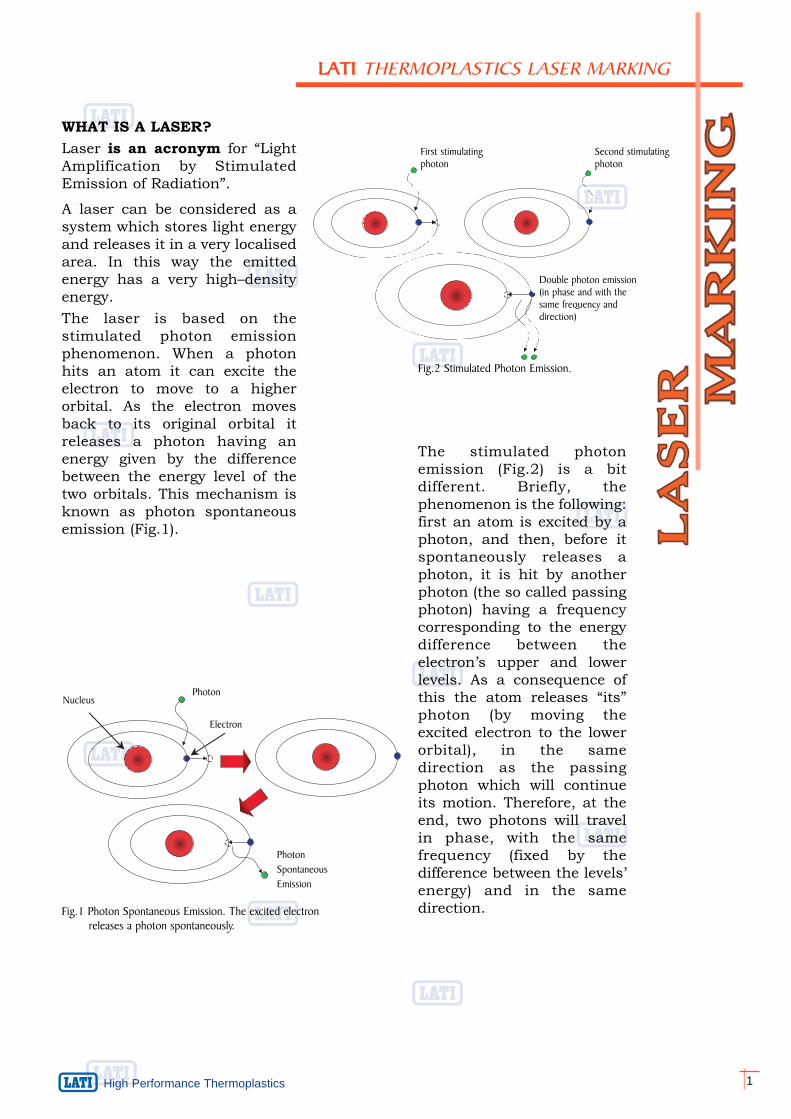
The stimulated photonemission (Fig.2) is a bitdifferent. Briefly, thephenomenon is the following:first an atom is excited by aphoton, and then, before itspontaneously releases aphoton, it is hit by anotherphoton (the so called passingphoton) having a frequencycorresponding to the energydifference between theelectron’s upper and lowerlevels. As a consequence ofthis the atom releases “its”photon (by moving theexcited electron to the lowerorbital), in the samedirection as the passingphoton which will continueits motion. Therefore, at theend, two photons will travelin phase, with the samefrequency (fixed by thedifference between the levels’energy) and in the samedirection.
NucleusPhoton
Electron
PhotonSpontaneousEmission
First stimulatingphoton
Second stimulatingphoton
Double photon emission(in phase and with thesame frequency anddirection)
Fig.2 Stimulated Photon Emission.
Fig.1 Photon Spontaneous Emission. The excited electron releases a photon spontaneously.
WHAT IS A LASER?Laser is an acronym for “LightAmplification by StimulatedEmission of Radiation”.
A laser can be considered as asystem which stores light energyand releases it in a very localisedarea. In this way the emittedenergy has a very high–densityenergy.The laser is based on thestimulated photon emissionphenomenon. When a photonhits an atom it can excite theelectron to move to a higherorbital. As the electron movesback to its original orbital itreleases a photon having anenergy given by the differencebetween the energy level of thetwo orbitals. This mechanism isknown as photon spontaneousemission (Fig.1).
2
Hig
h P
erfo
rman
ce T
herm
opla
stic
s
Laser beam
Acoustooptical cell Stimulatedemission
MediumEnergy source(Krypton lamp)
Spontaneous emission
Backmirror
Frontmirror
Laser beam leakage: thelaser passes throughthe front mirror as aleakage (5%)
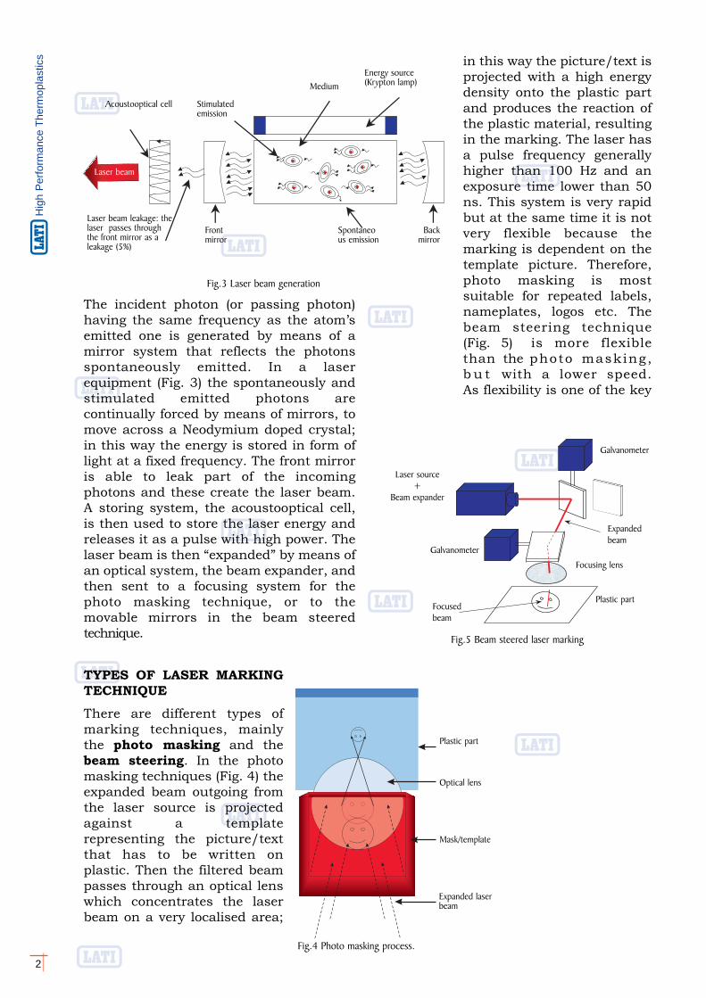
The incident photon (or passing photon)having the same frequency as the atom’semitted one is generated by means of amirror system that reflects the photonsspontaneously emitted. In a laserequipment (Fig. 3) the spontaneously andstimulated emitted photons arecontinually forced by means of mirrors, tomove across a Neodymium doped crystal;in this way the energy is stored in form oflight at a fixed frequency. The front mirroris able to leak part of the incomingphotons and these create the laser beam.A storing system, the acoustooptical cell,is then used to store the laser energy andreleases it as a pulse with high power. Thelaser beam is then “expanded” by means ofan optical system, the beam expander, andthen sent to a focusing system for thephoto masking technique, or to themovable mirrors in the beam steeredtechnique.
TYPES OF LASER MARKINGTECHNIQUEThere are different types ofmarking techniques, mainlythe photo masking and thebeam steering. In the photomasking techniques (Fig. 4) theexpanded beam outgoing fromthe laser source is projectedagainst a templaterepresenting the picture/textthat has to be written onplastic. Then the filtered beampasses through an optical lenswhich concentrates the laserbeam on a very localised area;
in this way the picture/text isprojected with a high energydensity onto the plastic partand produces the reaction ofthe plastic material, resultingin the marking. The laser hasa pulse frequency generallyhigher than 100 Hz and anexposure time lower than 50ns. This system is very rapidbut at the same time it is notvery flexible because themarking is dependent on thetemplate picture. Therefore,photo masking is mostsuitable for repeated labels,nameplates, logos etc. Thebeam steering technique(Fig. 5) is more flexiblethan the photo masking,b u t with a lower speed.As flexibility is one of the key
Plastic part
Optical lens
Mask/template
Expanded laserbeam
Fig.4 Photo masking process.
Laser source+
Beam expander
Galvanometer
Focusedbeam
Expandedbeam
Galvanometer
Focusing lens
Plastic part
Fig.5 Beam steered laser marking
Fig.3 Laser beam generation
High Performance Thermoplastics 3
LLAATTII THERMOPLASTICS LASER MARKING
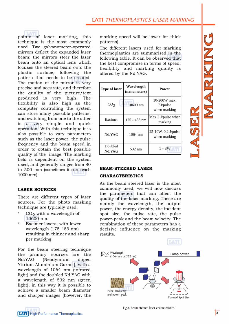
Type of laser Wavelength(nanometers) Power
CO2 10600 nm10-200W max,
6J/pulse when marking
Excimer 175 - 483 nmMax 2 J/pulse when
marking
Nd:YAG 1064 nm25-10W, 0.2 J/pulse
when marking
DoubledNd:YAG 532 nm 1 - 3W
Lamp powerWavelength (1064 nm or 532 nm)
Pulse- frequencyand power peak
Focused Spot Size
Fig.6 Beam-steered laser characteristics.
points of laser marking, thistechnique is the most commonlyused. Two galvanometer-operatedmirrors deflect the expanded laserbeam; the mirrors steer the laserbeam onto an optical lens whichfocuses the steered beam onto theplastic surface, following thepattern that needs to be created.The motion of the mirror is veryprecise and accurate, and thereforethe quality of the picture/textproduced is very high. Theflexibility is also high as thecomputer controlling the systemcan store many possible patterns,and switching from one to the otheris a very simple and quickoperation. With this technique it isalso possible to vary parameterssuch as the laser power, the pulsefrequency and the beam speed inorder to obtain the best possiblequality of the image. The markingfield is dependent on the systemused, and generally ranges from 80to 500 mm (sometimes it can reach1000 mm).
LASER SOURCESThere are different types of lasersources. For the photo maskingtechnique are typically used:· CO2 with a wavelength of
10600 nm. · Excimer lasers, with lower
wavelength (175-483 nm) resulting in thinner and sharpper marking.
For the beam steering techniquethe primary sources are theNd:YAG (Neodymium dopedYttrium Aluminium Garnet), with awavelength of 1064 nm (infraredlight) and the doubled Nd:YAG witha wavelength of 532 nm (greenlight); in this way it is possible toachieve a smaller beam diameterand sharper images (however, the
marking speed will be lower for thickpatterns).The different lasers used for markingthermoplastics are summarised in thefollowing table. It can be observed thatthe best compromise in terms of speed,flexibility and marking quality isoffered by the Nd:YAG.
BEAM-STEERED LASER CHARACTERISTICSAs the beam steered laser is the mostcommonly used, we will now discussthe parameters that can affect thequality of the laser marking. These aremainly the wavelength, the outputpower, the energy-density, the incidentspot size, the pulse rate, the pulsepower-peak and the beam velocity. Thecombination of these parameters has adecisive influence on the markingresults.

4
Hig
h P
erfo
rman
ce T
herm
opla
stic
s WavelengthThe wavelength is importantbecause the material has to absorbthe laser energy if a good markingeffect is to occur. The majority ofplastic materials are able to absorbthe laser energy at a wavelength of1064 nm (the wavelength of theNd:YAG, which falls in the infraredband); for those requiring a lowerwavelength the 532 nm, doubledNd:YAG could be used.
Lamp powerThe power of the outgoing beam isdependent on the energy of thelight source (for a Nd:YAG, theKrypton arc lamp is usually used).By increasing or decreasing theinput energy (lamp power), theoutput laser beam energy increasesor decreases accordingly.
Pulse Rate and Pulse PowerPeakGenerally the laser beam is notcontinuous, but it is pulsing atmedium-high frequencies. In thisway the energy stored in theacousto-optic cell is released in avery short time. The laser beamgenerator may be thought of as acapacitor that releases the storedcharge instantaneously, thusproducing high energy. The lowerthe frequency at which this energyis released the higher will be thepulse power and the consequenteffect. It can be observed that whenlow frequencies are used the effecton the plastic surface is materialvaporisation, due to the very rapidtemperature increase and the lowheat transmission inside the part.With high frequencies the materialvaporisation still occurs, but lessthan before, and the laser’sreleased energy results in atemperature rise in theneighbourhood of the exposedarea. Typically the frequency of thepulse varies from 1 to 50 kHz.
Focused Spot Size and Energy DensityThe output power alone is not enough toassure good laser marking. In fact, it isessential that this power is directedagainst a localised area. The device thatcontrols the spot size direction is calledthe focusing system. The diameter of thefocused laser beam on the work surfacedetermines both the marking line widthand the real marking efficiency. Thisdiameter is a function of the focal length ofthe lens and the divergence of the laserbeam. Simply stated, when the focal lengthis increased, the focusing spot size iscorrespondingly enlarged. The setting ofthe focal length affects two properties: firstthe incident spot size, and hence theenergy density (the lower the focal lengththe higher the energy density) , and secondthe marking field area (the higher the focallength the larger the marking field).
It should be noted that the size of thefocused spot is sometimes smaller thanthe line width required for plastic marking.Therefore, the characters or logos have tobe “written” more than once, to give theproper appearance and readability, byplacing several lines one close to the otheror by using a spiral trace to fill the thickpatterns.
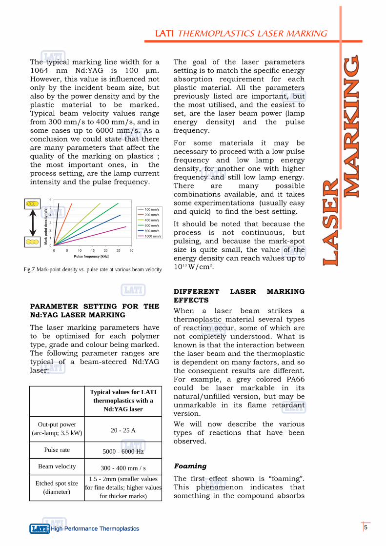
Beam Velocity (Marking Speed)The result of the combination of the pulserate and the beam displacement velocity isthe mark point overlap (or mark pointdensity). A good overlap results in acontinuous high quality marking, whereasa low density of mark-points produces apoor overlap. Too high the beamdisplacement speed on the part surfaceproduces a non continuous marked line,and the marking appears as a series ofspots. Too low a marking speed however,may result in an excessive mark depth orburning particularly nearby the etchedarea.
Fig.7 shows a correlation between thepulse rate, the mark-point density (ratiobetween the spot size and the distance tothe closest spot) and the beamdisplacement velocity. It clearly shows thatthe mark-point density can vary accordingto the pulse rate and beam velocity.
High Performance Thermoplastics 5
LLAATTII THERMOPLASTICS LASER MARKING
High Performance Thermoplastics
Out-put power (arc-lamp; 3.5 kW)
Pulse rate
Etched spot size(diameter)
1.5 - 2mm (smaller valuesfor fine details; higher values
for thicker marks)
Typical values for LATIthermoplastics with a
Nd:YAG laser
20 - 25 A
5000 - 6000 Hz
300 - 400 mm / sBeam velocity
The typical marking line width for a1064 nm Nd:YAG is 100 μm.However, this value is influenced notonly by the incident beam size, butalso by the power density and by theplastic material to be marked.Typical beam velocity values rangefrom 300 mm/s to 400 mm/s, and insome cases up to 6000 mm/s. As aconclusion we could state that thereare many parameters that affect thequality of the marking on plastics ;the most important ones, in theprocess setting, are the lamp currentintensity and the pulse frequency.
PARAMETER SETTING FOR THENd:YAG LASER MARKINGThe laser marking parameters haveto be optimised for each polymertype, grade and colour being marked.The following parameter ranges aretypical of a beam-steered Nd:YAGlaser:
Fig.7 Mark-point density vs. pulse rate at various beam velocity.
The goal of the laser parameterssetting is to match the specific energyabsorption requirement for eachplastic material. All the parameterspreviously listed are important, butthe most utilised, and the easiest toset, are the laser beam power (lampenergy density) and the pulsefrequency.
For some materials it may benecessary to proceed with a low pulsefrequency and low lamp energydensity, for another one with higherfrequency and still low lamp energy.There are many possiblecombinations available, and it takessome experimentations (usually easyand quick) to find the best setting.
It should be noted that because theprocess is not continuous, butpulsing, and because the mark-spotsize is quite small, the value of theenergy density can reach values up to1013 W/cm2.
DIFFERENT LASER MARKINGEFFECTS When a laser beam strikes athermoplastic material several typesof reaction occur, some of which arenot completely understood. What isknown is that the interaction betweenthe laser beam and the thermoplasticis dependent on many factors, and sothe consequent results are different.For example, a grey colored PA66could be laser markable in itsnatural/unfilled version, but may beunmarkable in its flame retardantversion. We will now describe the varioustypes of reactions that have beenobserved.
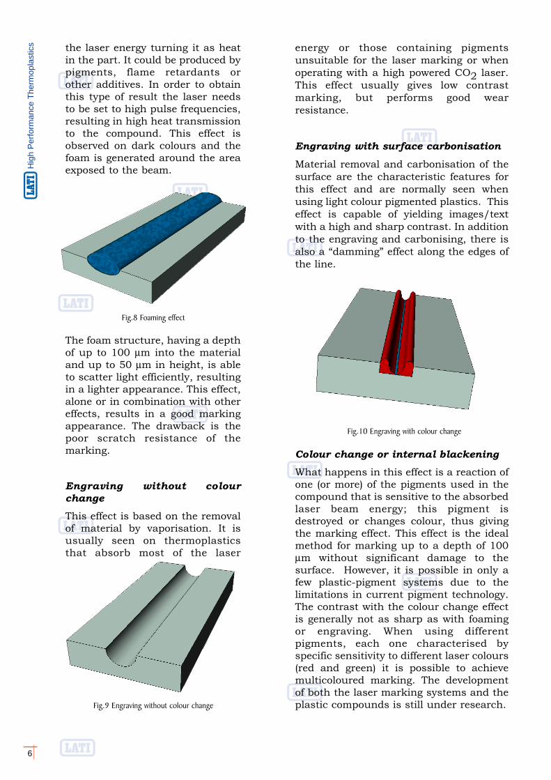
Foaming The first effect shown is “foaming”.This phenomenon indicates thatsomething in the compound absorbs
6
Hig
h P
erfo
rman
ce T
herm
opla
stic
s
Colour change or internal blackeningWhat happens in this effect is a reaction ofone (or more) of the pigments used in thecompound that is sensitive to the absorbedlaser beam energy; this pigment isdestroyed or changes colour, thus givingthe marking effect. This effect is the idealmethod for marking up to a depth of 100μm without significant damage to thesurface. However, it is possible in only afew plastic-pigment systems due to thelimitations in current pigment technology.The contrast with the colour change effectis generally not as sharp as with foamingor engraving. When using differentpigments, each one characterised byspecific sensitivity to different laser colours(red and green) it is possible to achievemulticoloured marking. The developmentof both the laser marking systems and theplastic compounds is still under research.
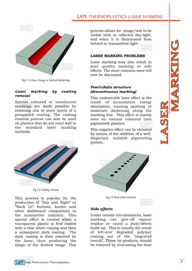
energy or those containing pigmentsunsuitable for the laser marking or whenoperating with a high powered CO2 laser.This effect usually gives low contrastmarking, but performs good wearresistance.
Engraving with surface carbonisationMaterial removal and carbonisation of thesurface are the characteristic features forthis effect and are normally seen whenusing light colour pigmented plastics. Thiseffect is capable of yielding images/textwith a high and sharp contrast. In additionto the engraving and carbonising, there isalso a “damming” effect along the edges ofthe line.
the laser energy turning it as heatin the part. It could be produced bypigments, flame retardants orother additives. In order to obtainthis type of result the laser needsto be set to high pulse frequencies,resulting in high heat transmissionto the compound. This effect isobserved on dark colours and thefoam is generated around the areaexposed to the beam.
The foam structure, having a depthof up to 100 μm into the materialand up to 50 μm in height, is ableto scatter light efficiently, resultingin a lighter appearance. This effect,alone or in combination with othereffects, results in a good markingappearance. The drawback is thepoor scratch resistance of themarking.
Engraving without colourchangeThis effect is based on the removalof material by vaporisation. It isusually seen on thermoplasticsthat absorb most of the laser
Fig.8 Foaming effect
Fig.10 Engraving with colour change
Fig.9 Engraving without colour change
process allows for image/text to bevisible both in reflected day-light,and when it is illuminated frombehind in transmitted light.
LASER MARKING PROBLEMSLaser marking may also result inpoor quality marking or sideeffects. The most common ones willnow be discussed.
Pearl-chain structure (discontinuous marking)This undesirable laser effect is theresult of inconsistent energyabsorption, causing spotting ormoderate darkening along themarking line. This effect is mainlyseen on natural coloured (nonpigmented) plastics.
This negative effect can be obviatedby means of the addition of a well-dispersed, suitable pigmentingsystem.
High Performance Thermoplastics 7
LLAATTII THERMOPLASTICS LASER MARKING
Fig.11 Colour change or internal blackening
Fig.12 Coating removal
Side effectsUnder certain circumstances, lasermarking can give-off vapourresidue or cause a dust/debrisbuild-up. This is usually the resultof left-over degraded polymercoming out of the “engravedtrench”. These by-products shouldbe removed by evacuating the dust
This process is popular for theproduction of “Day and Night” or“Back Lit” buttons, knobs, andother dashboard components inthe automotive industry. Thisspecial effect is created when atransparent plastic is first coatedwith a thin white coating and thena subsequent dark coating. Thedark coating is then removed bythe laser, thus producing theshape of the desired image. This
Laser marking by coatingremovalSpecial coloured or translucentmarkings are made possible byremoving one or more layers of apreapplied coating. The coatingremoval process can also be usedon plastics that do not react well tothe standard laser markingmethods.
Fig.13 Pearl-chain structure
8
Hig
h P
erfo
rman
ce T
herm
opla
stic
s even in case of moderate wear. Incomparison with other markingtechnologies, such as ink-pad printing, thelaser marks are significantly moreresistant to abrasion thanks to the higherthickness of the imprinted image.
Weatherability of Laser MarkingSome plastic and plastic/pigmentcombinations can change colour, fade orcan yellow when exposed to UV light. Thisapplies also to laser-marked surfaces. Thelargest factor in the mark alteration of alaser treated part surface is the weatheringstability of the polymer-pigmentcombination. Accelerated weathering testshave shown that a darker backgroundcolour normally fades faster than thelighter laser marking; notwithstandingthat the contrast ratio undergoes a slightdecrease only. Generally speaking it canbe assumed that the laser marking effectsare not badly affected by theweathering/ageing processes.
LASER MARKABILITY OFTHERMOPLASTICSThe necessary condition for laser markingis the absorption of the laser beam energyresulting in a colour change or similareffect. This may be achieved by thepolymer alone or through the addition ofpigments and/or additives.
Most non-pigmented thermoplastics (intheir natural colour) are not readily lasermarkable, or are only slightly markable,because they are not absorbent to thelaser light (the wavelength of the standardNd:YAG laser is 1064 nm).
Thermoplastics in their natural color canbe roughly divided into three categoriesaccording to their laser markability:
1.Thermoplastics with good absorptionand consequent carbonisation,resulting in an extensive darkening ofthe laser-exposed areas. Examplesinclude PES, PSU. PC.
2.Thermoplastics with inconsistentabsorption and carbonisation, resultingin an uneven marking (pearl-chaineffect). Examples include PS, SAN, ABS.
and venting the vapours. Incertain cases, laser marking canslightly lower the impact strengthof some notch-sensitive polymers.It may also reduce surface theresistivity of some specificpolymers/compounds.
No visible effectCertain polymers do not absorb theNd:YAG laser beam and thereforeare not markable. With suitablewell-dispersed pigments or otheradditives, these polymers can bemade laser markable.
MARKING QUALITY ANDSPECIFICATIONS
Optical EvaluationIndepending whether the markingis to be decorative or functional,high demands are often requiredfor the image quality. The qualityof the lines and of the image“filling” capacity are optimised andevaluated according to the fourmost important characteristics:contrast, uniformity, sharpness oflines, and surface.
The most important of these isusually the contrast. Contrast isthe relationship between thebrightness of the surfacebackground and that of themarking. The best contrast isobtained with a dark backgroundand light marking, or with a lightbackground and a dark marking.“Contrast” is very subjective; it isdependent not only on the qualityof the laser mark but also on otheraspects (i.e., the surface finish ofthe part).
Abrasion Resistance of LaserMarkingThe various marking effects, canproduce a line depth over 100 μm,assuring therefore a readable text
Critic material formulationsIt is rarely possible to predictwhether a given formulation willgive a good contrast with lasermarking. We at LATI are regularlytesting our various formulations tobetter understand which additivesare more effective for lasermarking, and which formulationsresult in better laser markability.For those formulations which donot give satisfactory results, wecontinue to try and research waysto improve the contrast whilemaintaining the properties andcharacteristics of the originalmaterial.
These tests have been largelycarried out particularly on self-extinguishing Polyamideformulations.
From our tests and experiencesthe following considerationsflow:1. Uncoloured (natural) PA and
PP/PE, whether unfilled, impactmodified, glass filled, or combi-nations of the above, do not laser mark.
2. Some colours are inherently “difficult” to laser mark. It is dif-ficult (or impossible) to obtain agood contrast with red, yellow and green base colours, espe-cially in resins like PA that are not inherently laser markable.
3. It is difficult to obtain a “good” contrast with some material/colour combinations, not because they are not laser markable, but because, as an example, the background colouritself is too dark to show good contrast with a dark mark. At the same time the background may be too light to show a goodcontrast with a light mark. This
High Performance Thermoplastics 9
LLAATTII THERMOPLASTICS LASER MARKING
Besides the styrenic polymers,this group includes also thepolyesters (PET, PBT). By addinga suitable pigment/additivecombination, the marking effectcan be made more uniformresulting in a high qualityimprint.
For both these groups, the properselection of the pigment/additivepackage for the dark backgrounds,can yield a light marking usuallyoff-white in colour.
3. Thermoplastics with little or noabsorption, resulting in poor orunreadable marks
This group includes PA, POM,PP, PE, PPS. In their natural,uncoloured state, they are notlaser markable. With theaddition of a specific darkpigment system, an almostwhite marking results. Some ofthese plastics, when pigmentedin light colours yield only a lightmarking. But with specialadditives, a dark print may alsobe obtained.
In short, everypolymer/compound and everycolour needs to be carefullyevaluated.
Laser markability can be greatlyinfluenced by mineral fillers,reinforcements, processing aids,flame retardants, and otheradditives. Contrary to popularbelief, the addition of glass fibres toa polymer reduces its markabilityonly slightly. In addition, somemineral fillers and/or flameretardants may reduce the lasermarkability due to their inherentcolour. On the other hand, theadditives contained in some flameretardant packages can have apositive effect on the contrast of themarking.
10
Hig
h P
erfo
rman
ce T
herm
opla
stic
s has been noticed on certain “medium grey” colours.
4. Moreover just because a materialis laser markable in one specificcolour, it is not possible to predict whether any other formulation (even only slightly modified)with the same colour, is also markable.
5. It is often possible to improve the laser contrast of a formula-tion (apart from natural PA, PP,PE, POM). This is achieved by modifying the additive and pig-ment formulation (selecting thepigments that are more respon-sive to laser light).However therecould be a negative effect on theproperties of the resulting com-pound, such that it is no longersuitable for the end-use. For example, formulations that are self-extinguishing may have some properties (including the flame resistance) negatively affected by the incorporation of additives for laser marking.
High Performance Thermoplastics 11
LLAATTII THERMOPLASTICS LASER MARKING
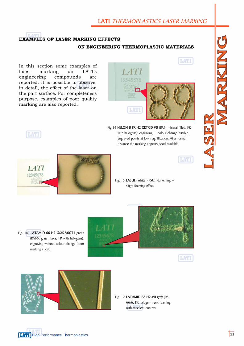
Fig. 16 LATAMID 666 HH2 GG/25-VV0CT1 green(PA66, glass fibres, FR with halogens):engraving without colour change (poormarking effect)
Fig.14 KELON BB FFR HH2 CCET/30-VV0 (PA6, mineral filled, FR with halogens): engraving + colour change. Visible engraved points at low magnification. At a normal distance the marking appears good readable.
Fig. 15 LASULF wwhite (PSU): darkening +slight foaming effect
In this section some examples oflaser marking on LATI’sengineering compounds arereported. It is possible to observe,in detail, the effect of the laser onthe part surface. For completenesspurpose, examples of poor qualitymarking are also reported.
Fig. 17 LATAMID 668 HH2-VV0 ggrey (PA 66/6, FR halogen-free): foaming, with excellent contrast
EXAMPLES OF LASER MARKING EFFECTSON ENGINEERING THERMOPLASTIC MATERIALS
12
Hig
h P
erfo
rman
ce T
herm
opla
stic
s
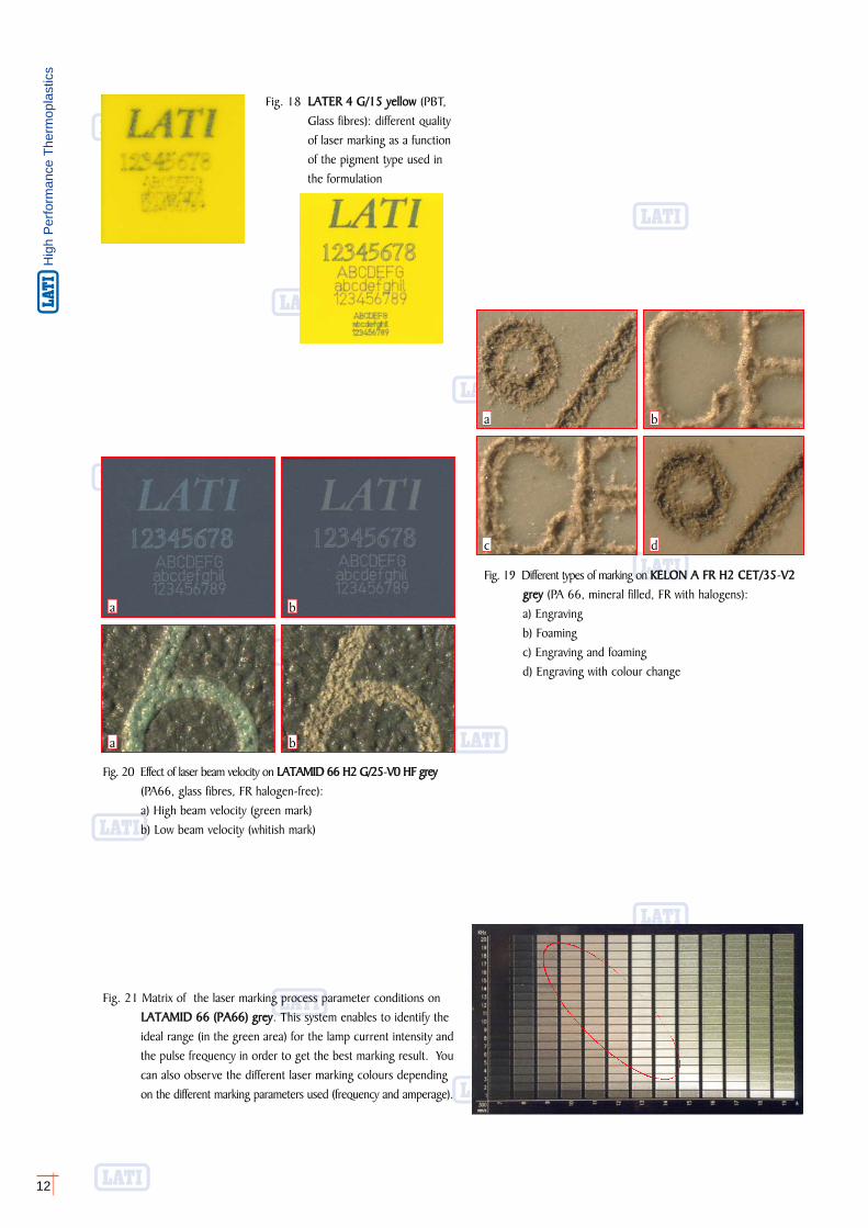
Fig. 21 Matrix of the laser marking process parameter conditions on LATAMID 666 ((PA66) ggrey. This system enables to identify the ideal range (in the green area) for the lamp current intensity andthe pulse frequency in order to get the best marking result. Youcan also observe the different laser marking colours depending on the different marking parameters used (frequency and amperage).
Fig. 19 Different types of marking on KELON AA FFR HH2 CCET/35-VV2 grey (PA 66, mineral filled, FR with halogens):a) Engravingb) Foamingc) Engraving and foamingd) Engraving with colour change
Fig. 18 LATER 44 GG/15 yyellow (PBT, Glass fibres): different qualityof laser marking as a functionof the pigment type used in the formulation
b
d
a
c
Fig. 20 Effect of laser beam velocity on LATAMID 666 HH2 GG/25-VV0 HHF ggrey(PA66, glass fibres, FR halogen-free): a) High beam velocity (green mark)b) Low beam velocity (whitish mark)
a b
a b
Values shown are based on testing of injection moulded laboratory test specimens, conditioned according to the practice and represent data that fall within the standard range of properties for non-coloured material. As they may be subject to variations, these valuesdo not represent a sufficient basis for any part design and are not intended for use in establishing values for specification purposes. Properties of moulded parts can be influenced by a wide range of factors including, but not limited to, colorants, part design,processing conditions, post-treatment and environmental conditions. This information and technical assistance are provided as a convenience for informational purposes only and are subject to change without notice. The customer shall always ensure that thelatest release is at his own disposal. Lati S.p.A. extend no warranties or guarantee, including a warranty of merchantability, and make no representations as to the accuracy, suitability, reliability, completeness and sufficiency of the information provided, and assumeno responsibility regarding the consequences of its use or for any printing errors. It is the customer's responsibility to inspect and test our products in order to determine to his own satisfaction whether they are suitable for his intended uses and applications or usedin conjunction with third-party materials. This application-specific analysis shall at least include preliminary testing to determine the suitability for the customer's particular purpose from a technical as well as health, safety, and environmental standpoint. Such testinghas not necessarily been done by us as the manner in which the customer use and the purpose to which utilise our products are beyond our control. Lati S.p.A. does not accept and hereby disclaims liability for, any damages whatsoever in connection with the useof or reliance on this information. No one is authorised to make any warranties, issue any immunities or assume any liabilities on behalf of Lati S.p.A. except in a writing signed by a specifically authorised Lati S.p.A. executive. Unless otherwise agreed in writing,the exclusive remedy for all claims is replacement of the product or refund of the purchase price at Lati's option, and in no event shall Lati S.p.A. be liable for special, consequential, incidental, punitive or exemplary damages. No information herein can be consideredas a suggestion to use any product in conflict with intellectual property rights. Lati S.p.A. disclaim any liability that may be claimed for infringement or alleged infringement of patents. Unless specifically stated in writing, the products mentioned herein are not suitablefor applications in the pharmaceutical, medical or dental sector, in contact with foodstuff or for potable water transportation. For any other issues Lati S.p.A. Conditions of Sales apply. Copyright © LATI S.p.A. 2008
International
High Performance Thermoplastics
salesorganisation
SSWWEEDDEENN
SCANDILATITERMOPLASTICI AB
Gullbergs Strandgata 36 A-CS - 41104 GÖTEBORGtel. +46 (0)31 - 7740236fax +46 (0)31 - 7740736
http://www.lati.com - e-mail: [email protected]
BBRRAASSIILL
LATI TERMOPLÁSTICOSDO BRASIL LTDA
AV. Prof. Gioia Martins, 206CEP: 05632-020 - SÃO PAULO - SP
tel. +55 (0)11 - 35024700fax +55 (0)11 - 35024700
http://www.lati.com - e-mail: [email protected]
AASSIIAA
LATI IndustriaTermoplastici S.p.A.
Via F. Baracca,7I - 21040 VEDANO OLONA (Va)
tel. +39 - 0332 409111fax +39 - 0332 409235
http://www.lati.com - e-mail: [email protected]
UUSSAA
LATI IndustriaTermoplastici S.p.A.
Via F. Baracca, 7I - 21040 Vedano Olona (Va)
tel. +39 - 0332 409111fax. +39 - 0332 409235
http://www.lati.com - e-mail: [email protected]
FFRRAANNCCEE
LATI FRANCE S.A.S.
Z.I. des Ebizoires, 4 Rue des Frères LumièreF - 78370 PLAISIR
tel. +33 (0)1 - 30791819fax +33 (0)1 - 30791818
http://www.lati.com - e-mail: [email protected]
GGEERRMMAANNYY
LATI IndustriaTermoplastici
Deutschland GmbHOtto-Von-Guericke-Ring, 7
D - 65205 WIESBADEN - Nordenstadttel. +49 (0)6122 - 90820
fax +49 (0)6122 - 908222http://www.lati.com - e-mail: [email protected]
SSPPAAIINN
LATI Ibérica, S.L.Unipersonal
C / Muntaner, 270 - Sobreático AE - 08021 BARCELONA
tel. +34 93 2097377fax +34 93 2011519
http://www.lati.com - e-mail: [email protected]
UUNNIITTEEDD KKIINNGGDDOOMM
LATI UK LTD.
Crewe Hall - Weston Road - The QuadrangleUK - Crewe - Cheshire CW1 6UA
tel. +44 (0)1270 - 501713fax +44 (0)1270 - 509713
http://www.lati.com - e-mail: [email protected]
IITTAALLYYLATI Industria Termoplastici S.p.A.
Via F. Baracca, 7I - 21040 VEDANO OLONA (Va)
tel. +39 - 0332 409111fax +39 - 0332 409307
http://www.lati.com - e-mail: [email protected]
Printed in Italy 08/01/2008/C&I.002