Thermomechanical Finite-Element Model of Shell Behavior in ...
22
Thermomechanical Finite-Element Model of Shell Behavior in Continuous Casting of Steel CHUNSHENG LI and BRIAN G. THOMAS A coupled finite-element model, CON2D, has been developed to simulate temperature, stress, and shape development during the continuous casting of steel, both in and below the mold. The model simulates a transverse section of the strand in generalized plane strain as it moves down at the casting speed. It includes the effects of heat conduction, solidification, nonuniform superheat dissipation due to turbulent fluid flow, mutual dependence of the heat transfer and shrinkage on the size of the interfacial gap, the taper of the mold wall, and the thermal distortion of the mold. The stress model features an elastic-viscoplastic creep constitutive equation that accounts for the different responses of the liquid, semisolid, delta-ferrite, and austenite phases. Functions depending on temperature and composition are employed for properties such as thermal linear expansion. A contact algorithm is used to prevent penetration of the shell into the mold wall due to the internal liquid pressure. An efficient two-step algorithm is used to integrate these highly nonlinear equations. The model is validated with an analytical solution for both temperature and stress in a solidifying slab. It is applied to simulate continuous casting of a 120 mm billet and compares favorably with plant measurements of mold wall temperature, total heat removal, and shell thickness, including thinning of the corner. The model is ready to investigate issues in continuous casting such as mold taper optimization, minimum shell thickness to avoid breakouts, and maximum casting speed to avoid hot-tear crack formation due to submold bulging. I. INTRODUCTION COMPUTATIONAL models are important tools to gain insight into thermal and mechanical behavior during complex manufacturing processes such as the continuous casting of steel billets. This process features many interacting phenom- ena which challenge modeling methods, shown in Figure 1(a). Starting with the turbulent flow of molten steel into the mold cavity, superheat is dissipated during flow recirculation in the liquid pool prior to solidifying a shell against the walls of a water-cooled copper mold. Heat transfer is controlled by conduction through the solidifying steel shell, the mold, and, especially, the size and properties of the interfacial layers between them. After initial solidification at the menis- cus, the shell tends to shrink away from the mold walls due to thermal contraction. Over most of the strand surface, inter- nal “ferrostatic pressure” from the head of molten metal main- tains good contact between the shell and the mold. However, shrinkage near the corners may create gaps or intermittent contact, which greatly lowers the local cooling rate. The extent of the gap depends on the composition-dependent shrinkage of the steel shell, its creep resistance, the casting speed, taper of the mold wall, thermal distortion of the mold wall, and the thermal properties of the material filling the interfacial gap. The mechanical behavior of the shell also controls the formation of defects such as hot-tear cracks and breakouts and depends on thermal shrinkage, high-temperature inelastic stress-generation rate, solid-state phase transformations, temperature, steel composition, mul- tidimensional stress state, and deformation rate. The harsh environment of the steel plant makes it difficult to conduct experiments during the process. To improve insight into these phenomena demands sophisticated mathematical mod- els, to aid the traditional tools of physical models, lab, and plant experiments. A thermal-mechanical finite-element model that incorpo- rates the aforementioned phenomena, named CON2D, has been developed in the Metals Processing Simulation Labo- ratory at the University of Illinois at Urbana-Champaign over the past decade [1–4] with several applications. [5–12] After a brief literature review, this article describes the features of the CON2D model. It then presents its validation with ana- lytical solutions and a simulation of a continuous steel bil- let casting process, where plant measurements were available for comparison. II. PREVIOUS WORK Many previous computational models have investigated thermal stress during the continuous casting of steel, includ- ing models of billet casting, [13–19] beam blanks, [20] slab cast- ing, [2,6,11,13,14,21–31] and thin-slab casting. [32,33,34] Brimacombe, Grill, and co-workers first applied computational thermal- stress models of a two-dimensional (2-D) billet section under plane stress [13,14] as it moved down the caster. These and similar early models [21,22,23] revealed important insights into crack formation, such as the need to avoid reheating. This infant stage of computational stress modeling was qualita- tive due to the lack of material properties at high tempera- ture, a simple elastic-plastic constitutive model, and coarse meshes due to computer limitations. Rammerstorfer et al. added a separate creep function in developing a thermoviscoelastic-plastic stress model of a transient one-dimensional (1-D) slice domain through a METALLURGICAL AND MATERIALS TRANSACTIONS B VOLUME 35B, DECEMBER 2004—1151 CHUNSHENG LI, Postdoctoral Student, and BRIAN G. THOMAS, Wilkins Professor of Mechanical Engineering, are with the Department of Mechanical and Industrial Engineering, University of Illinois at Urbana- Champaign, Urbana, IL 61801. Contact e-mail: [email protected] Manuscript submitted August 18, 2003.
Transcript of Thermomechanical Finite-Element Model of Shell Behavior in ...

Thermomechanical Finite-Element Model of Shell Behavior in Continuous Casting of Steel
CHUNSHENG LI and BRIAN G THOMAS
A coupled finite-element model CON2D has been developed to simulate temperature stress and shapedevelopment during the continuous casting of steel both in and below the mold The model simulates atransverse section of the strand in generalized plane strain as it moves down at the casting speed Itincludes the effects of heat conduction solidification nonuniform superheat dissipation due to turbulentfluid flow mutual dependence of the heat transfer and shrinkage on the size of the interfacial gap the taperof the mold wall and the thermal distortion of the mold The stress model features an elastic-viscoplasticcreep constitutive equation that accounts for the different responses of the liquid semisolid delta-ferriteand austenite phases Functions depending on temperature and composition are employed for propertiessuch as thermal linear expansion A contact algorithm is used to prevent penetration of the shell into themold wall due to the internal liquid pressure An efficient two-step algorithm is used to integrate thesehighly nonlinear equations The model is validated with an analytical solution for both temperature andstress in a solidifying slab It is applied to simulate continuous casting of a 120 mm billet and comparesfavorably with plant measurements of mold wall temperature total heat removal and shell thicknessincluding thinning of the corner The model is ready to investigate issues in continuous casting such asmold taper optimization minimum shell thickness to avoid breakouts and maximum casting speed toavoid hot-tear crack formation due to submold bulging
I INTRODUCTION
COMPUTATIONAL models are important tools to gaininsight into thermal and mechanical behavior during complexmanufacturing processes such as the continuous casting ofsteel billets This process features many interacting phenom-ena which challenge modeling methods shown in Figure 1(a)Starting with the turbulent flow of molten steel into the moldcavity superheat is dissipated during flow recirculation inthe liquid pool prior to solidifying a shell against the wallsof a water-cooled copper mold Heat transfer is controlledby conduction through the solidifying steel shell the moldand especially the size and properties of the interfaciallayers between them After initial solidification at the menis-cus the shell tends to shrink away from the mold walls dueto thermal contraction Over most of the strand surface inter-nal ldquoferrostatic pressurerdquo from the head of molten metal main-tains good contact between the shell and the mold Howevershrinkage near the corners may create gaps or intermittentcontact which greatly lowers the local cooling rate Theextent of the gap depends on the composition-dependentshrinkage of the steel shell its creep resistance the castingspeed taper of the mold wall thermal distortion of the moldwall and the thermal properties of the material fillingthe interfacial gap The mechanical behavior of the shellalso controls the formation of defects such as hot-tearcracks and breakouts and depends on thermal shrinkagehigh-temperature inelastic stress-generation rate solid-statephase transformations temperature steel composition mul-
tidimensional stress state and deformation rate The harshenvironment of the steel plant makes it difficult to conductexperiments during the process To improve insight intothese phenomena demands sophisticated mathematical mod-els to aid the traditional tools of physical models lab andplant experiments
A thermal-mechanical finite-element model that incorpo-rates the aforementioned phenomena named CON2D hasbeen developed in the Metals Processing Simulation Labo-ratory at the University of Illinois at Urbana-Champaign overthe past decade[1ndash4] with several applications[5ndash12] After abrief literature review this article describes the features ofthe CON2D model It then presents its validation with ana-lytical solutions and a simulation of a continuous steel bil-let casting process where plant measurements were availablefor comparison
II PREVIOUS WORK
Many previous computational models have investigatedthermal stress during the continuous casting of steel includ-ing models of billet casting[13ndash19] beam blanks[20] slab cast-ing[2611131421ndash31] and thin-slab casting[323334] BrimacombeGrill and co-workers first applied computational thermal-stress models of a two-dimensional (2-D) billet section underplane stress[1314] as it moved down the caster These andsimilar early models[212223] revealed important insights intocrack formation such as the need to avoid reheating Thisinfant stage of computational stress modeling was qualita-tive due to the lack of material properties at high tempera-ture a simple elastic-plastic constitutive model and coarsemeshes due to computer limitations
Rammerstorfer et al added a separate creep function indeveloping a thermoviscoelastic-plastic stress model of atransient one-dimensional (1-D) slice domain through a
METALLURGICAL AND MATERIALS TRANSACTIONS B VOLUME 35B DECEMBER 2004mdash1151
CHUNSHENG LI Postdoctoral Student and BRIAN G THOMASWilkins Professor of Mechanical Engineering are with the Department ofMechanical and Industrial Engineering University of Illinois at Urbana-Champaign Urbana IL 61801 Contact e-mail bgthomasuiucedu
Manuscript submitted August 18 2003
1152mdashVOLUME 35B DECEMBER 2004 METALLURGICAL AND MATERIALS TRANSACTIONS B
between the mold and shell This model also featured dif-ferent creep constants for modeling austenite and -ferrite andtemperature-dependent properties Similar models were devel-oped for slab sections[26] including some that assumed planestrain[27] Kelly et al[16] developed an axisymmetric modelof coupled thermal stress in round billets to study the effectof carbon content on the formation of longitudinal cracksElastic-stress analysis was performed on the mold and thebillet to determine the interfacial-gap profile followed byelastic-plastic stress analysis of the billet
Recently several improved models of the thermal-mechanicalbehavior of continuous-cast steel have been developedBoehmer et al[17] coupled a three-dimensional (3-D) in-househeat-flow model and a 2-D thermal-stress model in theADINA model to analyze a continuous-cast billet sectionin plane stress An elastoplastic constitutive model wasadopted including strain-rate-dependent strength and plas-ticity and a separate creep model if necessary The solid-ifying solid was discretized with a deforming grid and liquidelements were deleted from the stress simulation
A transverse-slice model AMEC2D was developed to simu-late beam-blank casting including elastic-viscoplastic behaviorand a simple fluid-flow model to account for superheat trans-port in the liquid pool[20] Park et al applied AMEC2D toinvestigate the effect of mold-corner radius on shell growthand longitudinal corner cracks in billets[18] This modelassumed plane stress and neglected the effects of superheatvariations
Huespe et al developed the Arbitrary Lagrangian-Eulerian[31]
and mixed Eulerian-Lagrangian[19] thermal-mechanical modelsto analyze stressstrain distributions in continuous-cast roundsteel billets These rigorous models adopt elastic-viscoplasticmaterial behavior with temperature- and history-dependent mater-ial parameters but are computationally intensive and assume2-D axisymmetry They show that the generalized plane-strainassumption matches closest to the real behavior short of a full3-D analysis
Many important related aspects of continuous casting havebeen modeled in depth and are discussed elsewhere[3536]
including fluid flow in the molten steel pool[37] nonequi-librium solidification of the shell[3538] thermal distortionof the mold[39] bulging and bending of the strand belowthe mold[4041] and crack prediction[3542]
Although they have generated important insights previousthermal-mechanical models of shell solidification in the moldstill oversimplify some phenomena or are too computation-ally expensive to simulate large-scale problems with suffi-cient mesh and time-step refinement to be accurate Thereis still a need for better models to gain more quantitativeinsight into thermal-mechanical behavior and crack predictionin continuous casting of steel
III GOVERNING EQUATIONS
The model solves the transient heat-conduction equationand corresponding force-equilibrium equation for tempera-ture displacement strain and stress in a transverse Lagrangianreference frame moving downward with the steel shell at thecasting speed as shown in Figure 1(a) Both 2-D and 1-Dslice domains are simulated as shown in Figures 1(b) and (c)respectively
(a)
(b)
(c)
Fig 1mdashModeling domain of casting billet (a) schematic of billet casting (b)L-shaped mess of three-node heat-transfer elements (shown) connected into six-node stress elements and (c) schematic of slice domain at the billet centerline
slab[24] Kristiansson[15] advanced the traveling-slice modelwith stepwise coupling of the thermal and stress computationswithin a 2-D billet section based on the interfacial gap
METALLURGICAL AND MATERIALS TRANSACTIONS B VOLUME 35B DECEMBER 2004mdash1153
A Heat-Transfer and Solidification Model
The model first solves the transient energy balance (Eq [1])where H(T) and k(T) are the isotropic temperature-dependententhalpy and conductivity respectively[43]
[1]
A 2-D simplification of the full 3-D process is reason-able because axial (z direction) heat conduction is negligi-ble relative to advection at the high Peacuteclet number of thissteel continuous casting process (vL 2 103)
v 00167 ms L 1 m 7500 kgm3 cp 06 kJkgK K 40 WmK
Applying the chain rule to the left-hand side of Eq [1]isolates the specific heat (cp) and latent heat (Lf) together ina convenient function partH(T)partT in Eq [2] Heat-balancenumerical errors are lessened by providing an enthalpy-temperature look-up function
[2]
Boundary conditions can be a fixed temperature heat fluxconvection or a heat-resistor model across the interfaciallayer between the mold wall and the steel surface[43] Thelatter enables the fully coupled heat-transfer and stress ana-lysis described in Section VIIndashC The thermal-property func-tions of different steels including conductivity and enthalpyare given in Section XndashB
B Stress Model
The general governing equation for the static-mechanicsproblem in this Lagrangian frame is given by the force-equilibrium balance in Eq [3][44]
[3]
Below the meniscus region axial temperature gradients andthe corresponding displacement gradients are generally smallso it is reasonable to apply a generalized plane-strain assump-tion in the casting direction This enables a 2-D transient-stress analysis to provide a reasonable approximation of thecomplete 3-D stress state Although this is not quite as accu-rate as a fully 3-D analysis[31] this slice-model approach canrealistically model the entire continuous casting process withthe possible exception of the meniscus region at a relativelysmall computational cost
The incremental governing equations acting over eachtime step (t) for the generalized plane-strain conditionsimplify Eq [3] to the following
[4]
intysz dA My
intxsz dA Mx
intsz dA Fz
sy
y
txy
x 0
sx
x
txy
y 0
sect s rb 0
raH(T )
Tb aT
tb
x ak (T )
T
xb
y ak(T )
T
yb
r
H (T)
T sect (k(T )sectT )
Incremental total strains are related to displacementsux uy uz according to Eq [5]
[5]
There are no body forces because the ferrostatic pressurecaused by gravity acting on the liquid is instead appliedthrough the internal boundary conditions described in Sec-tion IXndashB Besides the regular boundary conditions like fixeddisplacements and surface tractions a special type of bound-ary mold-wall constraint is included in CON2D to modelthe interactions between the mold wall and the steel surfaceas addressed in Section VIIIndashB The distorted shape of themold has an important influence on the size of the interfacialgap heat transfer and consequently stress and so is incor-porated as discussed in Section VIIIndashA
Twofold symmetry can be assumed in the current contin-uous casting application so the constants related to bending(b and c in Eq [5] and Mx and My in Eq [4]) all vanishand z represents the unconstrained axial (thickness) con-traction of each 2-D slice
IV CONSTITUTIVE MODELS
Increments of stress and elastic strain are related throughHookrsquos Law (Eq [6]) Matrix [D] contains the isotropictemperature-dependent elastic modulus (E(T)) and Poissonrsquosratio () given in Eq [7]
[6]
where x y xy zT x y xy z
T
[7]
The incremental total strains () in Eq [5] are com-posed of elastic (e) thermal (th) inelastic (in)and flow (flow) strain components as given in Eq [8]
[8]
The totals of all strains at a given time (t t) areobtained by accumulating the strain increments at each priortime step For example the total strain is accumulated asfollows (Eq [9])
[9]tt t tt
e th in flow
E 113v v 0 v
v 113v 0 v
0 0 1132v
2 0
v v 0 113v
U[D]
E(T)
(1 v)(1132v)
s [D]e [D]e
z a bx cy
xy 1
2 auy
x
ux
yb
y uy
y
x ux
x
1154mdashVOLUME 35B DECEMBER 2004 METALLURGICAL AND MATERIALS TRANSACTIONS B
A Thermal Strain
Thermal strains arise due to volume changes caused byboth temperature differences and phase transformationsincluding solidification and solid-state phase changes betweencrystal structures such as austenite and ferrite The isotropicthermal-strain vector th given in Eq [10] is based onthe phase fractions and the thermal linear-expansion func-tion (TLE) discussed in Section XndashC
[10]
B Inelastic Strain
Inelastic strain includes both strain-rate-independent plas-ticity and time-dependent creep Creep is significant at thehigh temperatures of this process and is indistinguishablefrom plastic strain Thus this work adopts a unified consti-tutive model of the mechanical behavior to capture the tem-perature- and strain-rate sensitivity of high-temperature steel
The inelastic strain rate is described by different con-stitutive models according to the microstructural state of thesolid steel
[11]
where and are the equivalent inelastic strain ratesof ferrite and austenite respectively as given in Section XndashDThe scalar inelastic strain-rate function follows the ferritefunction ( or ) whenever the phase fraction of ferriteexceeds 10 pct of the total volume This is justified by consid-ering the steel with two phases to act as a composite mater-ial in which only a small amount of the weaker ferrite phaseweakens the mechanical strength of the whole material Theplain-carbon steels treated in this work are assumed to hardenisotropically so the von Mises loading surface associatedplasticity and normality hypothesis in the PrandtlndashReuss flowlaw is applied[45]
[12]
where and are the plastic strain-rate tensorthe deviatoric-stress tensor the equivalent stress scalar (or vonMises effective stress) and equivalent inelastic strain-ratescalar respectively In this work the equivalent inelasticstrain rate bears a sign determined by the direction ofthe maximum principal inelastic strain as defined in Eq [13]in order to achieve kinematic behavior (Bauschinger effect)during reverse loading
[13]
where max max(in11in22in33) min min(in11in22in33)The ldquordquo operator indicates standard term-by-term tensor
multiplication Equations [12] and [13] allow an isotropic
where c micromax
|max|max min
min
|min|max min
in cA2
3
in in
in
inss
iquest
in
in
3
2 in
s iquests
in13gin13d
in d in13d pct d 10 pct
in13g pct d 10 pct
(in)
5thtt6 (TLE(T tt) 13 TLE (T t))51 1 0 16T
scalar to represent the 3-D strain-rate state Appendix Bdefines and Eq [12] in 2-D generalized plane-strainform Parameter c (1 or 131) makes the equivalent inelas-tic strain rate have the same sign as the maximum principalinelastic strain The functions for the inelastic strain-ratescalars described in Section XndashD must be integratedto find the in value needed in Eq [8] as described pre-viously in this section
C Strain in Liquid Elements
In this model the liquid elements are generally given nospecial treatment regarding material properties and finite-element assembly However liquid reacts very differentlyfrom solid under external loads It deforms elastically underhydrostatic force like a solid but deforms dramatically undershear force If any liquid is present in a given finite elementa constitutive equation is used to generate an extremely rapidcreep (shear) rate
[14]
The parameter A is chosen to be 15 108 MPa131s131 tomatch the viscosity of molten steel[46] Equation [14] isanother format of the linear viscous equation[43] of the lam-inar fluid which is a reasonable assumption for the liquidsteel in the mushy zone Liquid deforms under any nonzeroshear stress according to Newtonian fluid dynamics Thusyield should be zero To avoid numerical difficulty howeveryield is treated as a tolerance-accuracy parameter with nophysical nature and is given a value of 001 MPa
This method effectively increases shear strain and thusenforces negligible liquid strength and shear stress The crit-ical temperature where the liquid fraction is sufficient tomake the element act as a liquid is the ldquocoherency tempera-turerdquo (Tcoherency) currently defined as being equal to thesolidus temperature To generalize this scalar strain rate toa multidimensional strain vector the same PrandtlndashReussEqs [12] and [13] are used as for the solid
This fixed-grid approach avoids the difficulties of adap-tive meshing while allowing strain to accumulate in themushy region As in the real continuous casting process thetotal mass of the liquid domain is not constant The inelasticstrain accumulated in the liquid represents mass transportdue to fluid flow and so is denoted ldquoflow strainrdquo Positiveflow strain indicates fluid feeding into the region This isimportant for the prediction of hot-tear cracks The disad-vantage of using this high-creep-rate function to model liquidis the increased computational difficulty at the solidificationfront This requires the use of a very robust local iterationalgorithm[3]
V FINITE-ELEMENT IMPLEMENTATION
A Heat-Transfer and Solidification Model
The three-node triangle finite element was employed toapproximate temperature in the domain as a piecewise lin-ear function The standard Galerkin method[44] applied toEq [2] gives the following global matrix equations
[15][K ]T [C]T Fq Fqsup
in
flow e cA1 |c| 13 yield 20
|c| yield
|c| yield
in
ss
iquest
METALLURGICAL AND MATERIALS TRANSACTIONS B VOLUME 35B DECEMBER 2004mdash1155
where [K] is the conductance matrix including the effect ofconductivity (k(T)) and [C] is the capacitance matrix includ-ing the effect of specific heat and latent heat in H(T) Withineach element an effective specific heat (cpe) is evaluated usinga spatial averaging technique suggested by Lemmon[47]
[16]
The [K] and [C] matrices are found from their element matri-ces given in Appendix A through standard finite-element methodsummation over the domain A three-level time-stepping methodproposed by Dupont et al[48] was adopted to solve Eq [15]Temperatures at the current time t t are found from the tem-peratures at the previous two time steps t and t 13 t
[17]
[18]
Substituting Eqs [17] and [18] into Eq [15] and rearranginggives a recursive global matrix equation expressing the time andspatial discretization of the heat-conduction equation (Eq [2])
[19]
Equation [19] is solved at each time step for the unknownnodal temperatures Ttt using a Choleski decompositionsolver[49] The terms Fq and Fqsup are the heat-flow-loadvectors containing the distributed heat flux at the domainboundary and the superheat flux at the internal moving bound-ary respectively On each domain boundary where heat fluxis applied the contributions from each element on the bound-ary are summed as follows
[20]
where Lij is the distance between node i and j The heat-fluxfunction (q) is specified such as being equal to the qgap valuegiven in Section VII The term Fqsup is calculated simi-larly with a different set of boundary elements using qsup
in Section VII
B Stress Model
Applying the standard Galerkin method to Eqs [4] through[7] gives the following set of linear equations over the finite-element domain
[21] 5Ff p6tt 13 Fel
t
[K]utt Fthtt Fin
tt
boundary elements
a microqij
Lij
2qij
Lij
2
part
Fq aboundary elements
int[N]T q dL
131
4[K ] 5Tt13t 6
[C]
tTt
c 34
[K] [C]
t d Ttt Fq Fqsup
T e Ttt 13 Tt
tf
T 1
4 53Ttt Tt13t6
cpe H
T a aH
x b2
aH
y b2
aT
x b2
aT
y b2
where [K] Fth Fin Ffp and Fel are the stiffnessmatrix and incremental force vectors due to incremental ther-mal strain inelastic strain ferrostatic pressure and externalsurface tractions at specified boundaries and elastic-straincorrections from the previous time step respectively Referto Eqs [64] through [67] in Appendix B for more details Ateach time step Eq [21] is solved for the incremental dis-placements (u) using the Choleski method[49] and thetotal displacements are updated via Eq [22]
[22]
Then the total strains and stresses are updated from Eqs [5]and [6] respectively The six-node quadratic-displacement tri-angle elements use the same grid of nodes that were connectedinto three-node elements for the heat-flow calculation Furtherdetails are given in Appendix B
VI INTEGRATION OF THE CONSTITUTIVEMODEL
Highly strain-rate-dependent inelastic models require arobust numerical integration technique to avoid numericaldifficulties The nonlinear equations to be integrated aregiven in Eqs [23] and [24] by combining Eqs [6] through[8] neglecting the second term on the right-hand side ofEq [6]
[23]
[24]
The incremental equivalent plastic strain accumulated overa time step is given in Eq [25] based on a highly nonlin-ear constitutive function which depends on and whichchange greatly over the time step
[25]
where F is one of the constitutive functions given in Eqs [46][47] or [14] depending on the current material state Substi-tuting Eqs [12] and [25] into Eqs [23] and [24] and using afully implicit time-stepping method a new set of evolutionequations are obtained as follows
[26]
[27]
Two tensors and and one scalar com-prise 13 unknown scalar fields for 3-D problems or nineunknowns for the 2-D problem here which require the solu-tion of Eqs [26] and [27] Zhu implemented an alternatingimplicit-explicit mixed time-integration scheme which isbased on an operator-splitting technique that alternatesbetween local and global forms of the total strain incre-ment and inelastic strain rate over each pair of successivesteps[3] Within each time step and are first solvedin
tts
tt
intt
s
tt
intt in
t F(T s tt intt pct C)t
133
2 F(T stt tt
in pct C ) s
ttiquests
tt tbs
tt D
tt a
t13 th
t 13 in
t
13 thtt t
intt F(T s tt in
tt pct C)t
ins
intt t
in intt
13 th
tt13 in
tt 2s
tt D
tt 1 t13 th
t 13 in
t
tt
utt ut u
1156mdashVOLUME 35B DECEMBER 2004 METALLURGICAL AND MATERIALS TRANSACTIONS B
using a fully implicit time-integration technique based onthe current best estimation of the total strain increment which is taken from the previous time step This is aldquolocal steprdquo because it is spatially uncoupled
Then the improved estimates of and from thelocal step are used to solve for by explicit finite-elementspatial integration through Eqs [21] and [5] This is a ldquoglobalsteprdquo[3]
There is still a tensor unknown in Eq [26] which makeseven the local time-integration step computationally chal-lenging Lush et al transformed this tensor equation intoa scalar equation for isotropic materials with isotropichardening[50]
[28]
where is the equivalent stress of the stress tensor defined subsequently
[29]
Equations [27] and [28] form a pair of nonlinear scalarequations to solve in the local step for estimates of the twounknowns and
Stress-Model Numerical Integration Procedure
Implementing the general 3-D procedure described pre-viously for the 2-D generalized plane-strain assumption theintegration procedure used in CON2D within each time stepis summarized as follows
(1) Estimate based on u from the previous timestep
(2) Calculate and needed to define the direction of the stress vector
[30]
(3) Solve the following two ordinary differential equationssimultaneously for and at each local Gausspoint using a fully implicit bounded NewtonndashRaphsonintegration method from Lush et al[50] This method givesthe best robustness and efficiency of several alternativeapproaches evaluated[3] Function F is either theKozlowski model III for (Eq [46]) the power law for (Eq [47]) or the flow strain for liquid phase (Eq [14])
[31]
(4) Expand this scalar stress estimate into vector form
[32]
(5) Calculate from and using the appropriateF values for the local material phase
intt
sttin
tt
stt stt
siquesttt
s tt 1
3 sm
tt dT
sztt d 1 1 0 1
siquesttt stt 131
3 sm
tt dT smtt sx
tt sytt
stt
s tt133mttF (T stt in
tt pct C)t
intt in
t F (T s tt intt pct C )t
ˆ s ttintt
13thttt1 1 0 1T 2
stt [D]tt1t 13 tht13in
t ˆ
siquestttstt s [B]ut
sttin
tt
s
tt D
tt (
t13 th
t 13 in
t
13 th
tt t
s
ttstt
stt s
tt13 3m
tt F(T stt intt pct C)t
intt
s
tt
t
(6) Expand this scalar inelastic-strain estimate into a vec-tor with the same direction as usingthe PrandtlndashReuss Eq [12] update
only for solidified elements(7) Use classic finite-element method spatial integration
(Appendix B) to solve Eq [21] for utt based on
(8) Finally find tt from utt and update t t
and tt
Overall this alternating implicit-explicit scheme withthe bounded NewtonndashRaphson iteration gives the best robust-ness and efficiency of several alternative finite-elementmethod time-integration approaches evaluated[3]
VII TREATMENT OF THE MOLDSHELLINTERFACE
Heat transfer does not depend directly on the force-equilibrium equation because the mechanical dissipationenergy is negligible The heat-flow and stress models arefully coupled with each other however when the gapbetween the mold and steel shell is taken into accountShrinkage of the shell tends to increase the thermal resis-tance across the gap where the shell is strong enough topull away from the mold wall This leads to hot and weakspots on the shell This interdependence of the gap size andthe thermal resistance requires iteration between the heat-a priori and stress models As the gap size is unknownadvance the heat resistance is also unknown Thus itera-tions within a time step are usually needed Contact betweenthe mold wall and shell surface is discussed in Section VIIIndashB
A Interface Heat Transfer
When the coupled heat-transfer and thermal-stress analysisis performed the heat-transfer boundary condition at the steelsurface is described by a gap heat-resistor model shown inFigure 2 with parameter values listed in Table I Heat leaves
in
tt
in
tttin
tt int
siquestttin
tt
Fig 2mdashSchematic of thermal resistor model of the interfacial layer betweenmold and billet
Table I Parameters of the Interface Model
Cooling water heat-transfer coefficienthwater (Wm2 K) 22000 to 25000
Cooling water temperature Twater (degC) 30 to 42Mold wall thickness dmold (mm) 6Mold wall conductivity kmold (Wm K) 360Gap conductivity kgap (Wm K) 002Contact resistance rcontact (m2 KW) 6 10134
Mold wall emissitivity 05Steel emissitivity 08
METALLURGICAL AND MATERIALS TRANSACTIONS B VOLUME 35B DECEMBER 2004mdash1157
the steel shell via conduction and radiation across the inter-facial gap It is then conducted across the thin copper moldand extracted by cooling water flowing across the back of themold tube The temperature and the heat-convection coefficientof the cooling water are input from the results of a preliminarycomputation using the CON1D model described elsewhere[51]
The contact resistance adopted in this model is several ordersof magnitude larger than the physical contact resistance[46]
between a flat steel and copper surface because it includes theinfluence of oscillation marks[51] The gap thickness is calcu-lated during each iteration from the shell-surface displacementand the mold wall position according to the local values ofthe mold taper and distortion which are described in the nextsection Once the gap size is determined the heat flux (qgap)across the interfacial layer between the mold wall and steel sur-face is solved together with the mold hot-face temperature (Tmold)
[33]
where
B Gap-Size Calculation
The gap thickness (dgap) is estimated for each boundarynode at the shell surface based on gaps from the previousiteration (n)
[34]
where u n dwall dtaper dmolddist and dgapmin are the displace-ment vector at boundary nodes unit-normal vector to themold wall surface mold wall position mold wall positionchange due to mold distortion and the minimum gap thick-ness respectively A positive dgap value indicates a real spacebetween the mold and shell
The minimum gap value is set as
[35]dgapmin rcontact kgap
dwalltt dtaper
tt 13 dmolddisttt
where
d gapn1 max1u(dgap
n ) n 13 dwalltt dgapmin 2
rgap dgap
kgap rcontact
rmold dmold
hwater kmold
hwater kmold
Tmold 567 10138 e Tshell
4 Tshellgtrmold Twatergtrgap
1gtrmold 1gtrgap
e 1
1m
1s
1
hrad 567 10138e(Tshell Tmold)(Tshell2 Tmold
2 )
rgapmold 1
hwater
Tmold
kmold
dgap
kgap rcontact
1 hrad adgap
kgap rcontactb
qgap Tshell13Twater
rgapmold
It physically represents the effective oscillation-mark depthat the shell surface When the calculated gap size is less thanthis minimum gap size then the contact resistance (rcontact)dominates heat transfer between the shell surface and themold wall Gap-size variation within the minimum gap sizeis assumed not to affect the thermal resistance which accele-rates convergence
C Thermal-Stress Coupling
The overall flow of CON2D is shown in Figure 3 Withineach time step the computation alternates between the heat-transfer and stress models through the following fully coup-led procedure
(1) The temperature field is solved based on the currentbest estimation of gap size from the previous time stepwith Eq [34] The initial gap size at the beginning ofthe simulation is simply zero around the strand perimeteras the liquid steel at the meniscus flows to match themold contour
(2) The incremental thermal strain is evaluated from thetemperature field at the current and previous time steps(Eq [10]) The inelastic strain is estimated by integrat-ing Eq [31] following the procedure described in Sec-tion VI The global matrix equation Eq [21] is solvedfor displacements strains and stresses using the stand-ard finite-element method
(3) The gap sizes for the next iteration are updated by
[36]
where is chosen to be 05(4) Finally steps 1 through 3 are repeated until the gap-size
difference between two successive heat-transfer andstress iterations n and n 1 is small enough
[37]
where nb is the number of boundary nodes When ddiff
becomes smaller than the specified ldquogap tolerancerdquo (dmin)the gap size is considered converged
VIII MODELING THE MOLD WALL
The mold wall affects the calculation in two ways (1)altering the size of the interfacial gap and associated heattransfer between the mold and strand through its distortedshape and (2) constraining the shell from bulging due tothe internal ferrostatic pressure
A Mold Wall Shape
The mold wall is defined in CON2D as a function ofdistance below the meniscus The shape of the mold variesfrom its dimensions at the meniscus due to mold taper andmold distortion The mold is tapered to follow the shrink-age of the steel strand to prevent excessive gaps from form-ing between the mold wall and shell surface as well as
ddiff a anb1dgap
n1 13 dgapn 22
anb1dgap
n1 22
dgapn1 b
dgapn1 (1 13 b)dgap
n
1158mdashVOLUME 35B DECEMBER 2004 METALLURGICAL AND MATERIALS TRANSACTIONS B
Fig 3mdashFlow chart of CON2D
preventing bulging of the shell Linear taper is defined byproviding the percentage per meter as follows
[38]
where W vc and t are the mold width casting speed and cur-rent time below the meniscus respectively As the modeledsection of the steel strand moves down from the meniscusthe mold wall distorts away from the solidifying shell andtapers toward it
Mold distortion arises from two main sources thermalexpansion of the mold wall due to heating during operationand mold wear due to friction between the mold and thestrand For the billet-casting simulation presented here molddistortion is considered to be simple thermal expansion asfollows ignoring residual distortion and mold wear
[39]dmolddist amold
W
2 1T13T0 2
dtaper pct Taper m
100 W
2 vc t
where is the average temperature through the mold wallthickness as a function of the distance below the mold exit
is the average mold wall temperature where the solid shellbegins at the meniscus mold is the thermal-expansion coef-ficient of the copper mold tube and W is the section width
Arbitrary complex mold shapes can be modeled by provid-ing an external data file or function with mold wall positionsat different distances below the meniscus and even aroundthe perimeter For example complex 3-D mold distortion pro-files[52] were used for slab casting simulations with CON2D[26]
B Contact Algorithm for Shell-Surface Constraint
The mold wall provides support to the solidifying shell beforeit reaches the mold exit A proper mold wall constraint is neededto prevent the solidifying shell from penetrating the mold wallwhile also allowing the shell to shrink freely Because the exactcontact area between the mold wall and the solidifying shell isnot known a priori an iterative solution procedure is needed
T0
T
METALLURGICAL AND MATERIALS TRANSACTIONS B VOLUME 35B DECEMBER 2004mdash1159
Some early finite-element models solved contact prob-lems by the Lagrange multiplier approach which introducesnew unknowns to the system as well as numerical difficult-ies[53] This work adopts a method developed and imple-mented by Moitra[26] which is tailored to this particularcasting-problem domain It solves the contact problem onlyapproximately but is easy to implement and is more sta-ble Iteration within a time step proceeds as follows
At first the shell is allowed to deform freely without moldconstraint Then the intermediate shell surface is comparedto the current mold wall position A fraction of all penet-rating nodes identified by Eq [40] is restrained back to themold wall position by a standard penalty method and thestress simulation is repeated
[40]
where dpen is the specified penetration tolerance Iterationcontinues until no penetration occurs
The nodes to be constrained are chosen by checking threescenarios
(1) In Figure 4(a) a portion of the shell surface with lengthL penetrates the mold and the maximum penetration is
u n 13 dwall 13dpen
found at the centerline of the strand face Those shellboundary nodes in the half of this violated length near-est to the face center (Lc) are constrained in the nextiteration
(2) In Figure 4(b) the center of the shell surface penet-rates the mold but does not penetrate the most Thoseviolated nodes from the maximum penetration positionto the face center are constrained in the next iteration
(3) In Figure 4(c) the center of the shell surface does notpenetrate the mold That half of the violated nodes closestto the face center is constrained in the next iteration
Commercial software such as ABAQUS generally con-strains violated nodes one by one until convergence isreached The present method is believed to be more com-putationally efficient for the particular quarter mold andbehavior of interest in this work The friction between theshell and mold surface is ignored in this model This wouldneed to be added to consider phenomena such as transversecracks due to excessive taper
IX SOLIDIFICATION FRONT TREATMENT
A Superheat Flux
Superheat is the amount of heat stored in the liquid steelthat needs to be extracted before it reaches the liquidus tem-perature Superheat is treated in one of two ways (1) the heat-conduction method and (2) the superheat-flux method Theheat-conduction method simply sets the initial steel tempera-ture to the pouring temperature and increases the conductiv-ity of the liquid by 65 times to crudely approximate the effectsof fluid flow This method equally distributes the superheatover the solidification front In reality the superheat distrib-ution is uneven due to the flow pattern in the liquid pool
The second method first obtains the superheat-flux dis-tribution from a separate fluid-flow computation such asdone previously for billets[54] or slabs[55] This superheat fluxat a given location on the strand perimeter is applied toappropriate nodes on the solidification front Specificallyit is applied to the two nodes just below the liquidus in those3-node elements with exactly one node above the liquidusThis is shown in Figure 5 where the isotherm is the liq-uidus The initial liquid temperature is set just above the liq-uidus to avoid accounting for the superheat twice
(a)
(b)
(c)
Fig 4mdash(a) through (c) Three types of penetration modes in contactalgorithm
Fig 5mdashSchematic of how ferrostatic pressure is applied at the internalboundary
1160mdashVOLUME 35B DECEMBER 2004 METALLURGICAL AND MATERIALS TRANSACTIONS B
B Ferrostatic Pressure
Ferrostatic pressure greatly affects gap formation by encour-aging contact between the shell and mold depending on theshell strength The ferrostatic pressure is calculated by
[41]
where z is the distance of the current slice from the meniscusfound from the casting speed and the current time Ferro-static pressure is treated as an internal load that pushes theshell toward the mold wall as shown in Figure 5 It is appliedequally to those two nodes just below the coherency tempera-ture that belong to those three-node elements having exactlyone of its three nodes above the Tcoherency isotherm It isassembled to the global force vector through Eq [64] inAppendix B which gives
[42]
where Lij is the boundary length between nodes i and j withina three-node element
X MATERIAL PROPERTIES
This work adopts temperature-dependent steel propertieschosen to be as realistic as possible
A Phase-Fraction Model
A pseudobinary-phase diagram for certain plain-carbonsteels developed from measurements by WON[56] is incor-
Other elements besides iron and carbon are 152 wt pct Mn 0015 wtpct S 0012 wt pct P and 034 wt pct Si
porated to produce realistic phase-fraction evolution betweenthe solidus and liquidus temperatures Figure 6 shows thenonequilibrium Fe-C phase diagram which defines the vol-ume fractions of liquid -ferrite and austenite used in thiswork The classical lever rule is used to calculate phase frac-tions in each two-phase region and a lever rule for ternarysystems is used in the three-phase region[57] The 100 and
Ffp amoving boundary elements
microFp
Lij
2Fp
Lij
2
part
Fp rgz
75 pct solid lines are compared with zero strength tempera-ture (ZST) and zero ductility temperature (ZDT) measurementsby Schmidtmann et al[38] They match very well
Figure 7 shows the phase fractions thus generated as afunction of temperature for the 004 pct C carbon steel whichis used in Section XIII Note that the liquid fraction decreasesparabolically as the steel cools from its liquidus This agreeswith a more sophisticated microsegregation model[38]
B Thermal Properties
The temperature-dependent conductivity function for plain-carbon steel is fitted from measured data compiled byHarste[58] and is given in Eq [43] Figure 8 shows the con-ductivity for several typical plain-carbon steels The conduc-tivity increases linearly through the mushy zone to the liquidby a factor of 65 to partly account for the effect of convec-tion due to flow in the liquid steel pool[55]
(1 13 a1(pct C)a2) Ka (8091 13 99269 10132 T(degC) 4613 10135 T(degC)2)
where
K(WmK) Ka fa Kg fg Kd fd Kl fl
Fig 6mdashNon-equilibrium Fe-C phase diagram[38] used in CON2D
Fig 7mdashFraction as a function of temperature for the 004C steel
Fig 8mdashConductivity of plain carbon steels
METALLURGICAL AND MATERIALS TRANSACTIONS B VOLUME 35B DECEMBER 2004mdash1161
[43]
The enthalpy curve used to relate heat content and tem-perature in this work H(T) is obtained by integrating thespecific heat curve fitted from measured data complied byHarste[58] as given in Eq [44] Figure 9 shows the enthalpyfor typical plain-carbon steels
where
H
H(kJKg) Ha fa Hg fg Hd fd Hl fl
a2 0209 109 10133 T(degC)
a1 0425 13 4385 10134 T(degC) Kl 390
Kd (2014 13 9313 10133T(degC))(1 13 a1(pct C)a2)
Kg 216 13 835 10133T(degC)
[44]
For the multiphase region both conductivity and enthalpy arecalculated by weighted averaging of their different phase frac-
Hl 0825T (K) 13 105
where ad [18(pct C) 20 103(pct C)2]
(44(pct C) 1200)
Hd 0441T (K) 887 10135T(K)2 51 ad
where ag [37(pct C) 19 103(pct C)2]
(44(pct C) 1200)
Hg 043T (K) 75 10135T(K)2 93 ag
Fig 9mdashEnthalpy of plain carbon steels
tions ( f ) The subscripts ( and l) in Eqs [43] and [44]represent -ferrite austenite -ferrite and liquid respectivelyDensity is assumed constant (7400 Kgm3) in order to main-tain constant mass
C Thermal Linear Expansion
The thermal linear-expansion function is obtained fromsolid-phase density measurements complied by Harste[58]
and Harste et al[59] and liquid density measurements byJimbo and Cramb[60]
[45]
A simple mixture rule is applied to obtain the overall densityfrom the values of the different phases Figure 10 shows thethermal linear-expansion curves for typical plain-carbonsteels assuming the arbitrary reference temperature T0 tobe the solidus temperature
D Inelastic Constitutive Properties
The unified constitutive model developed here uses theinstantaneous equivalent inelastic strain rate as the scalar-state function which depends on the current equivalent stresstemperature steel carbon content and the current equivalentinelastic strain which accumulates below the solidus temper-ature[616263] The model was developed to match tensile-testmeasurements of Wray[62] and creep-test data of Suzuki et al[64]
in
(T(degC) 13 1550)rl 7100 13 73(pct C) 13 (08 13 009(pct C))
rd 100(8011 13 047T(degC))
(100 13 (pct C))(1 0013(pct C))3
rg 100(8106 13 051T(degC))
(100 13 (pct C))(1 0008(pct C))3
ra 7881 13 0324T(degC) 13 3 10135T(degC)2
r(Kgm3) ra fa rg fg rd fd rl fl
where
TLE B3 r(T0)
r(T)13 1
Fig 10mdashThermal linear expansion (TLE) of plain carbon steels
5188 T(K)131 13 86 0505T(K)T(K) 800
13 655 10135 T(K)2 15 10137 T(K)3
13 111 106 T(K)131 13 472 T(K)800 T(K) 1000
2292 10133 T(K)2 405613 115 T(K) 6238 10133 T(K)2
1000 T(K) 1042 57803487 T(K) 13 0016013 T(K)2
1042 T(K) 106013 1837913 10068 T(K) 29934 10133 T(K)2
1060 T(K) 118413 521766 106 T(K)131 12822
h
1162mdashVOLUME 35B DECEMBER 2004 METALLURGICAL AND MATERIALS TRANSACTIONS B
Model III by Kozlowski given in Eq [46] is adopted to simu-late the mechanical behavior of austenite
[46]
where the direction of (c) is given in Eq [13] except usingthe principal stresses instead of principal strain components
A power-law model was developed to model the behav-ior of -ferrite[11] given as follows
[47]
Figure 11 compares the stresses measured by Wray[62] tothose predicted by the constitutive models at 5 pct strainintegrated under different constant strain rates The constitutivemodels give acceptable performance This figure also showsthat -ferrite which forms at higher temperatures found nearthe solidification front is much weaker than austenite Thisgreatly affects the mechanical behavior of the solidifyingsteel shell
n (1617 10134 T(K) 13 006166)131
m 1394156 10135 T(K) 0349501
fC 13678 104(pct C)1355610132
Fd cs (MPa)
fc(T(K)300)1355211 1000|in| 2mwhere
in13d(1s) 01Fd |Fd|n131
s
12 105(pct C)2
fpctC 4655 104 714 104(pct C)
f3 8132 13 154 10133T(K)
f2 1306289 1114 10133T(K)
f1 1305 13 5128 10133T(K)
Fg cs (MPa) 13 f1in |in|
f2131
where
in13g(1s) fpctC|Fg| f3131 Fg exp a134465 104
T(K)b
A simple mixture rule is not appropriate in two-phaseregions that contain interconnecting regions of a much weakerphase Thus the constitutive model given in Eq [47] is appliedin the solid whenever the volume fraction of ferrite (-ferriteabove 1400 degC -ferrite below 900 degC) is more than 10 pctOtherwise Eq [46] is adopted
To make the constitutive model properly handle kinematichardening during reverse loading the equivalent stressstrainused in Eqs [46] and [47] is given the same sign as the princi-pal stressstrain having the maximum magnitude The inelasticstrain rate as a consequence also bears a sign
Two uniaxial tensile experiments[4263] and a creep experi-ment[64] on plain-carbon steel at elevated temperatures weresimulated by CON2D to test the performance of its constitu-tive models Figures 12(a) and (b) show CON2D predictionsof tensile-test behavior of austenite and delta-ferrite at constantstrain rate around 10134 s131 which is typically encounteredin the shell during continuous casting[63] The results also com-pare reasonably with experiments at small strain (5 pct)although they overpredict the stress when the strain exceeds5 pct Because the strain generally stays within 5 pct for theentire continuous casting process the constitutive modelsare quite reasonable for this purpose Figure 13(a) shows theCON2D predictions of creep-test behavior at constant loadThe inelastic-strain predictions match the measurements rea-
Fig 11mdashComparison of CON2D predicted and measured stress[62] at 5 pctplastic strain
(a)
(b)
Fig 12mdashCON2D predictions compared with tensile-test measurements[4262]
(a) Koslowski III law for austenite[61] against tensile test measurements[62]
and (b) Power law for -ferrite[3] against tensile test measurements[62]
METALLURGICAL AND MATERIALS TRANSACTIONS B VOLUME 35B DECEMBER 2004mdash1163
(b)(a)
Fig 13mdashPredicted behavior of austenite compared with creep and cyclic loading test measurements at 1300 degC[64] (a) constant load and (b) alternating load
sonably well especially at times shorter than 50 seconds ofmost concern to continuous casting in the mold region Beyondthis time CON2D underpredicts creep which is consistentwith the overprediction of stress observed in the tensile testcases Monotonic loading is unlikely beyond this length oftime anyway Figure 13(b) compares CON2D predictions andcreep-test measurements[64] under a sinusoidal alternating loadwith full reversal (R ratio 1167) Although more measure-ments and computations of complex loading conditions wouldbe helpful these comparisons show that the constitutive mod-els in CON2D are reasonable even for conditions that includereverse loading
E Elastic Properties
The temperature-dependent elastic-modulus curve used inthis model is a stepwise linear fit of measurements byMizukami et al[65] given in Figure 14 Unlike in some othermodels the elastic modulus of the liquid here was given thephysically realistic value of 10 GPa The Poisson ratio isconstant at 03 Measurements of higher Poisson ratios athigh temperature are attributed to creep occurring during theexperiment Incorrectly incorporating part of the volume-conserved plastic behavior where 05 into the elasticv would cause numerical difficulty for the solver
Fig 14mdashElastic modulus for plain carbon steels used in CON2D[65]
XI NUMERICAL PERFORMANCE
A 2-D transient elastic-viscoplastic thermal-stress simu-lation with solidification internal pressure and contact is achallenging problem even for a supercomputer The efficientalgorithms in CON2D allow the complete solution of prac-tical problems in reasonable times with reasonable accuracyCoupling between the thermal and stress models can causeinstability however unless parameters such as time-stepsize tolerances of gap size and penetration are carefullychosen Current experience indicates that the initial time stepfor a fully coupled simulation with mold wall constraintshould be 00001 seconds which is 10 times smaller thanthe smallest time step size adopted for the uncoupled ther-mal-stress simulation by Zhu[3] The time-step size can beincreased twentyfold up to 0005 seconds as the simulationprogresses Increasing the time-step size further does notspeed up the simulation due to the need for more in-stepiterations It takes about 72 hours to perform a completefully coupled 19-second mold simulation of a 120 120mm billet with 7381 nodes on a PENTIUM IV 17 GHz
PENTIUM is a trademark of the Intel Corporation Santa Clara CA
workstation running the WINDOWS 2000 Professional oper-
WINDOWS is a trademark of the Microsoft Corporation Redmond CA
ating system using less than 500 MB of random-access mem-ory The corresponding simulation without coupling allowslarger time steps (0001 to 05 seconds) and takes only about5 hours Below-mold simulations allow even larger steps andtake only about 1 hour[66]
Reasonable tolerances should be specified to achieve satis-factory gap-size convergence while avoiding excessive moldwall penetration The minimum gap dgapmin is chosen here tobe 0012 mm which is less than the effective thickness of theoscillation marks and surface roughness Gaps smaller than thisare considered to be converged Thus the effective oscillationmark-depth dominates the heat resistance across the gap andmust be determined either by measurement or calibration Thetolerance for the mold wall penetration dpen is chosen to be0001 mm which is on the order of the incremental displacementbetween two consecutive time steps Too large a tolerance tends
1164mdashVOLUME 35B DECEMBER 2004 METALLURGICAL AND MATERIALS TRANSACTIONS B
to make the simulation inaccurate while too small a tolerancemakes the program overreact to small penetrations and slowsdown the simulation The best value of dpen depends on theproblem Generally a smaller value is needed when the simula-tion region of interest is closer to the meniscus
XII MODEL VALIDATION
An analytical solution of the thermal-stress model in an uncon-strained solidifying plate derived by Weiner and Boley[67] isused here as an ideal validation problem for solidification-stressmodels Constants for this validation problem were chosen hereto approximate the conditions of interest in this work and arelisted in Table II
The material in this problem has elasticndashperfect plastic behav-ior The yield stress drops linearly with temperature from 20 MPaat 1000 degC to 0 MPa at the solidus temperature of 149435 degCFor the current elastic-viscoplastic model this constitutive rela-tion was transformed into a computationally more challengingform the highly nonlinear creep function of Eq [14] with A 15 108 and yield 001 MPa in the liquid A very narrowmushy region 01 degC is used to approximate the single melt-ing temperature assumed by Boley and Weiner In addition tothe generalized plane-strain condition in the axial z direction asimilar condition was imposed in the y direction (parallel to thesurface) by coupling the displacements of all nodes along thetop surface of the slice domain as shown in Figure 1(c) Theanalytical solutions were computed with MATLAB[68]
Figures 15 and 16 show the temperature and the stress dis-tributions across the solidifying shell at different solidificationtimes using an optimized mesh and time step similar to thatadopted for the 2-D billet-casting simulation The mesh wasgraduated increasing in size from 03 mm at the left-hand endto 20 mm at right-hand end and the time-step size increasedfrom 0001 seconds at the beginning to 01 seconds at the end
Figures 17 and 18 show the relative average errors given inEq [48] for the temperature and stress predictions respectively
[48]
Accuracy of the CON2D predictions increases if the meshand time step are refined together A fine uniform mesh of01 mm with a small uniform time step of 0001 secondsproduces relative average errors within 1 pct for temperatureand within 2 pct for stress However the computational costis also high Note that the inaccuracy is severe at early timesof the simulation especially for the stress predictions This isbecause the solidified layer initially spans only a few elementsAs the solid portion of the plate grows thicker the meshsize and time-step requirements become less critical Thus anonuniform mesh with increasing time-step size is better tosatisfy both accuracy and efficiency The optimal choiceused in Figures 15 and 16 gives a decent prediction withthe relative average errors within 2 pct for temperature and3 pct for stress A similar mesh was adopted for the actual
Errors (pct) aN
13 1si
CON2D 13 si
Analytical22N |s (Tmelt) 13 s (Tcold)|
100
ErrorT (pct) aN
13 1Ti
CON2D 13 TiAnalytical22
N |Tmelt 13 Tcold| 100
Table II Constants Used in Boley and WeinerAnalytical Solution
Conductivity (Wm K) 330Specific heat (kJkg K) 0661Latent heat (kJkg) 2720Elastic modulus in solid (GPa) 400Elastic modulus in liquid (GPa) 140Thermal linear expansion coefficient (1K) 000002Density (kgm3) 75000Poissonrsquos ratio 03Melting temperature Tmelt (degC) 14944Liquidus temperature (degC) 149445Solidus temperature (degC) 149435Cold surface temperature Tcold (degC) 10000
Fig 15mdashTemperatures through an infinite solidifying plate at differentsolidification times compared with Boley amp Weiner analytical solution
Fig 16mdashStresses through an infinite solidifying plate at different solidifi-cation times compared with Boley amp Weiner analytical solution
billet-casting simulation This demonstrates that the modelis numerically consistent and has an acceptable mesh
XIII APPLICATION TO BILLET CASTING
The CON2D model was next applied to simulate a planttrial conducted at POSCO (Pohang works South Korea[18])for a 120-mm-square section billet of 004 pct C steel castat 22 mmin where measurements were available The mold
METALLURGICAL AND MATERIALS TRANSACTIONS B VOLUME 35B DECEMBER 2004mdash1165
(a) (b)
Fig 17mdashTemperature error between CON2D and analytical solution[67] from convergence studies (a) time-step size effect and (b) mesh size effect
shell using the 2-D L-shaped domain (Figure 1(b)) and aslice domain through the centerline of the billet face (Fig-ure 1(c)) similar to the Boley and Weiner analytical problemThe interfacial heat-transfer constants for both simulationsare given in Table I and were found with the help of a ded-icated heat-transfer code CON1D[51]
The superheat-flux profile was obtained from coupled com-putations of turbulent flow and heat transfer in a round bil-let caster by Khodadadi et al[54] for the case of a Grashofnumber (Gr gW3 (TLE(Tpour) 13 TLE(Tm))v2) of 1 108This value is the closest case to the current problem conditions
(a)
(b)
Fig 18mdashStress error between CON2D and analytical solution[67] from con-vergence studies (a) time-step size effect and (b) mesh size effect
had a single linear taper of 0785 pctm Details of the mater-ial and operation conditions are given in Tables III and IVrespectively Two simulations were performed to predict thetemperature stress and deformation evolutions of the billet
Table IV Simulation Conditions in Billet Plant Trial
Billet section size (mm mm) 120 120Working mold length (mm) 700Total mold length (mm) 800Casting speed (mmin) 22Mold corner radius (mm) 4Taper (pct m) 0785 (on each face)Time to turn on ferrostatic
pressure (s) 25Mesh size (mm mm) 01 01 to 14 10Number of nodes
(varies with section size) 7381Number of elements
(varies with section size) 7200Time step size (s) 00001 to 0005Pouring temperature (degC) 15550Coherency temperature (degC) 15109Gap tolerance dmin 0001 (01 pct)Minimum gap dgapmin (mm) 0012Penetration tolerance dpen (mm) 0001
Table III Material Details in Billet Plant Trial
Steel composition (wt pct) 004CLiquidus temperature (degC) 1532170 pct solid temperature (degC) 1525290 pct solid temperature (degC) 15189Solidus temperature (degC) 15109Austenite -ferrite starting temperature (degC) 78136Eutectoid temperature (degC) 71122
1166mdashVOLUME 35B DECEMBER 2004 METALLURGICAL AND MATERIALS TRANSACTIONS B
Fig 19mdashSuper heat flux used in CON2D for billet casting simulation
where the Grashof number is 2 107 and confirms thatnatural convection is unimportant in this process The heatflux was calculated from the Nusselt number (Nu) and meanliquid temperature (Tm) results given as a function of distancebelow the meniscus[54] using their values of liquid steel con-ductivity k 298 WmK mold section size W 200 mmand 33 degC superheat except for readjusting the superheat tem-perature difference as follows
[49]
where Tpour and Tliq are the pouring and liquidus temperaturesrespectively The resulting superheat-flux profile is shown inFigure 19 Note that the total heat integrated from Figure 19over the mold surface 486 kW matches the superheat forthe current problem (Tpour 13 Tliq)cpc 46 kW
The heat-flux and mold wall temperatures predicted byCON2D along the billet-face center are shown in Figures 20and 21 respectively These results slightly underpredict themeasurements of thermocouples embedded in the mold wallwhich should lie almost exactly between the hot- and cold-face temperatures[69] The total heat extracted by the mold
qsup Nu k(Tm 13 Tliq)
W
( Tpour 13 Tliq)Posco
(Tpour 13 Tliq)Khodadadi
(1285 kW) is 17 pct lower than the plant measurements basedon a heat balance of the mold cooling water (8 K temperaturerise at a 92 ms slot velocity) of 154 kW[18] This is consistentwith underprediction of the mold temperatures
The predicted shell growth for this CON2D simulationis given in Figure 22 as indicated by the evolution of thesolidus and liquidus isotherms This is compared with mea-surements of the solidliquid interface location obtainedby suddenly adding FeS tracer into the liquid pool duringsteady-state casting[18] Longitudinal and transverse sectionsthrough the billet were cut from the final product The trans-verse section was 285 mm from the meniscus when the FeStracer was added Because FeS tracer cannot penetrate thesolid steel shell sulfur prints of sections cut through thefully solidified billet reveal the location of the solidificationfront and shell-thickness profile at a typical instant duringthe process[18] The CON2D predictions match along thecenterline beyond the first 80 mm below the meniscus wherethe shell remains in contact with the mold suggesting thatthe heat-transfer parameters are reasonably accurate
The shell-surface-position profile down the centerline isshown in Figure 23 together with the mold wall position whichincludes both the taper and the mold-distortion profile calcu-
Fig 20mdashPredicted instantaneous heat flux profiles in billet casting mold
Fig 21mdashPredicted mold wall temperature profiles compared with plantmeasurements
Fig 22mdashPredicted shell thickness profiles for billet casting compared withplant measurements
METALLURGICAL AND MATERIALS TRANSACTIONS B VOLUME 35B DECEMBER 2004mdash1167
lated from the CON1D temperature results using Eq [39][51]
The shell surface generally follows the mold wall with no obvi-ous penetration validating the contact algorithm Note how-ever that a slight gap opens up within the first 25 mm Althoughthis effect is believed to be physically reasonable owing to rapidinitial shrinkage of the steel it is exaggerated here owing tonumerical difficulties during the initial stages of solidificationThis causes an overprediction of the drop in initial heat fluxand temperature observed in Figure 20 This drop is followedby increased heat flux (and corresponding mold wall temper-ature) after full contact is re-established which has also beenobserved in other measurements[70]
The simulation features a detailed prediction of temperatureshrinkage and stress in the region of the rounded billet cor-ner The evolution of the increases in gap size and surfacetemperature are given in Figures 24 and 25 near (20 mm) tothe centerline of the billet face and at various locations 0 510 and 15 mm from the billet corner The correspondinglarge drops in heat flux are included in Figure 20 The solidi-fying shell quickly becomes strong enough to pull the billetcorner away from the mold wall and form a gap around thecorner region The gap greatly decreases local heat flow inthe corner causing the mold wall temperature to drop
The drop in mold temperature near the corner over theinitial 80 mm is more than expected in reality because the
simple mold model of CON2D in Eq [33] neglects heat con-duction around the corner and along the casting directionThus these predictions are not presented This lattereffect which is included in CON1D[51] also contributed tothe convergence difficulties along the centerline discussedin Figure 23 Fortunately it has little other effect on heatflux or shell behavior
Figure 24 shows how a permanent gap forms after 40 mmbelow the meniscus which grows to over 03-mm thick byhalfway down the mold growing little after that Correspondinggaps form adjacent to the corner at later times reaching smallermaxima partway down the mold These gaps form because thesimple linear taper of the mold walls was insufficient to matchshrinkage of the shell The corner effect decreases with distancefrom the corner and disappears beyond 15 mm from the corner
The corner gap and drop in heat flux cause a hot spot at thecorner region as shown in the surface-temperature profiles ofFigure 25 The CON2D model predicts that the shell cornerreheats slightly and becomes 150 degC hotter than billet-facecenter for the conditions of this trial The decreased heat fluxalso produces less solidification in the corner as illustrated inFigure 26 at 285 mm below the meniscus The predicted shell
Fig 23mdashMold distortion mold wall position and shell surface profiles forthe billet casting simulation
Fig 24mdashGap evolution predicted by CON2D for the billet castingsimulation
Fig 25mdashShell surface temperatures predicted for billet casting simulation
Fig 26mdashTemperature contours at 285 mm below meniscus compared withcorresponding sulfur print from plant trial
1168mdashVOLUME 35B DECEMBER 2004 METALLURGICAL AND MATERIALS TRANSACTIONS B
thinning around the corner is consistent with the plant measure-ments from the sulfur print as quantified in Figures 22 and 26The predictions here are also consistent with those of Park etal who modeled how increasing the billet-mold corner radiusleads to more severe hot and thin spots near the corner[18] Thistends to validate the CON2D model and the simple constantinterfacial heat-transfer parameters used to produce these resultsImproving the accuracy would likely require a more complexmodel of gap heat transfer that considered details of surfaceroughness including differences between the center and corner
Figure 27 shows the evolution of surface-stress componentsnear the centerline of the billet face Stress normal to thesurface (x direction) is effectively equal to zero which indicatesthat the 0785 pctm mold taper never squeezes the billet Thestress components perpendicular to the solidification direction(y direction tangential to the surface and z casting direction)are generally very similar which matches the behaviorexpected from the analytical test solution[67] These stressesgrow slowly in tension during the period of increasing heat-extraction rate from 20 to 100 mm below the meniscus Theyreach a maximum of almost 3 MPa due to the increase inshell strength at lower temperature that accompanies the trans-formation from -ferrite to austenite This is shown in thethrough-thickness profile of these same stress components inFigure 28(a) but is calculated with the 1-D slice domain Thesurface tensile-stress peak does not penetrate very deep owingto the very thin layer of material colder than 10 pct delta-ferrite Thus this peak might cause very shallow fine surfacecracks but nothing deeper
The surface stresses in Figure 27 suddenly turn compressivebeyond 100 mm due to the sudden change in heat-extractionrate at this distance (Figure 20) Surface compression arisesbecause the subsurface begins to cool and shrink faster thanthe surface This causes a corresponding increase in subsurfacetension near the solidification front that might lead to subsurfacecracks The surface stays in compression from 134 to 136 MPafor the remaining time in the mold
During the time beyond 100 mm the stress profile (Fig-ure 28(b)) is qualitatively similar to that of the analyticaltest problem as expected Differences arise from the vari-ation in steel strength between the -ferrite and austeniteStresses in the liquid mushy zone and -ferrite are always verysmall Tensile stress increases rapidly during the phase transfor-
mation which takes place at the low end of the regionof Figure 28 When the -ferrite region is thin this tensilestress is more likely to create strains significant to generatecracks These results illustrate the widely accepted knowl-edge that surface cracks initiate near the meniscus whilesubsurface cracks form lower down
Figures 29(a) and (b) show the different components ofstrain (y direction) through the shell thickness near the billet-face center corresponding to the stresses in Figure 28 Ther-mal strains dominate in the solid and generate the otherstrains due to the constraint of adjacent layers of steel Smallelastic strains are generated by the mismatch of thermalstrain although the stresses they generate may still be sig-nificant Inelastic strain is generated in regions of high stressstarting in the region It is high at the surface at thetop of the mold and later grows in the austenite Note thatinelastic strains are all tensile throughout the shell The and mushy zones behave elastically with very low stressesThis is fortunate as these phases are very weak and cannotaccommodate much inelastic strain before cracking Flowstrain in the liquid occurs to accommodate the total strainwhich is naturally flat owing to the constraint by the solid
Figure 30 shows the ldquohooprdquo stress component (y direc-tion parallel to the billet surface and perpendicular to the
Fig 27mdashSurface stress histories predicted near the billet face center (2-DL-mesh domain)
Fig 28mdashStress and temperature predicted through the shell thickness farfrom billet corner (slice domain) (a) 100 mm below meniscus and (b) moldexit (700 mm below meniscus
(a)
(b)
METALLURGICAL AND MATERIALS TRANSACTIONS B VOLUME 35B DECEMBER 2004mdash1169
casting direction) at an off-corner location (10 mm abovethe billet corner) through the shell thickness at 100 500 and700 mm (mold exit) below the meniscus Stresses all behavesimilarly to the corresponding locations along the billet center-line except that the tension and compression are lower This is
expected due to the slower cooling rates shallower temper-ature gradients and higher temperatures near the corner
Figures 31 and 32 show contours of the stress and inelas-tic strain components perpendicular to the solidification direc-tion superimposed on the distorted billet at the mold exit withisotherms The insufficient 0785 pctm taper of this mold isunable to support the billet which allows a slight bulge (025 mmat the mold exit) Regions of high tensile stress and inelasticstrain are indicated at the off-corner subsurface (10 to 20 mmfrom the corner and 2 to 6 mm beneath the surface)
XIV CONCLUSIONS
A transient two-dimensional finite-element model has beendeveloped to quantify the temperature stress and strain dis-tributions in the solidifying shell in the continuous casting ofsteel This is a Lagrangian approach in generalized plane strainthat reasonably predicts the 3-D stress and strain state by solvingenergy- and force-balance equations within a 2-D transverseslice domain Superheat dissipation and ferrostatic pressure areboth taken account of through internal boundary conditionsUnified elastic-viscoplastic constitutive models for both theaustenite and -ferrite phases of the steel match tensile- andcreep-test data Liquid is given physically reasonable proper-ties including a high viscoplastic shear rate and small yield
(a)
(b)
Fig 29mdashStrain components predicted through the shell thickness far awayfrom billet corner (slice domain) (a) 100 mm below meniscus and (b) moldexit (700 mm below meniscus)
Fig 30mdashStress predicted through the shell thickness near billet corner (2-D L-mesh domain)
Fig 31mdashStress contours predicted at mold exit
Fig 32mdashInelastic strain contours predicted at mold exit
1170mdashVOLUME 35B DECEMBER 2004 METALLURGICAL AND MATERIALS TRANSACTIONS B
stress A robust and efficient time-integration technique thealternating local-global method is adopted to integrate thehighly nonlinear constitutive equations An efficient contactalgorithm allows the model to properly treat shell-surface inter-action with the mold wall
The model is validated by extensive comparisons with ananalytical solution of thermal stress in an infinite solidify-ing plate which justify the choice of mesh and time-stepsize The model is applied to simulate a 120-mm-square bil-let continuously cast at 22 mmin and the results comparefavorably to in-plant measurements of thermocouples embed-ded in the mold walls heat balance on the cooling waterand thickness of the solidified shell
The CON2D model is a useful tool to gain quantitativeunderstanding of issues pertaining to the thermal-mechanicalbehavior of the solidifying shell during the continuous castingof steel slabs and billets It is being applied to investigatetaper in billets[71] and slabs[72] minimum shell thickness toavoid breakouts[30] maximum casting speed to avoid longitu-dinal cracks due to off-corner bulging below the mold[66] andother phenomena[75]
ACKNOWLEDGMENTS
The authors thank the steel industry members of the Con-tinuous Casting Consortium at UIUC for their financial supportof this project Work by previous students A Moitra H Zhuand J Parkman on the CON2D program is also gratefullyacknowledged The authors also thank the National Centerfor Supercomputing Applications (NCSA) for computationalresources
APPENDIX A
Finite-element implementation of heat-transfer model
A Linear Temperature Triangles
The small triangles in Figure [A1] show the constant tem-perature-gradient triangle element used for the heat-flowmodel Temperature within an element is interpolated by thesame shape functions used to interpolate the coordinates
[A1]
The [B] matrix in global coordinate system can be obtained as
[A2]
where A is the area of the triangle element
B Conductance Matrix and Capacitance Matrix
The element conductance and capacitance matrices neededto assemble Eq [15] are given in Eqs [A3] and [A4][73]
[A3]
[A4][C ]el int[N ]T rcpe
[N]dA rcpeA
12pound
2 1 1
1 2 1
1 1 2
sect
[K ]el int[B]T c ke 0
0 ked [B]dA
[B] 1
2Ac y2 13 y3 y3 13 y1 y1 13 y2
x3 13 x2 x1 13 x3 x2 13 x1d
T a3
i1Ni (x y)Ti
where ke is the average conductivity of the three nodal valueswithin each element and cpe is the effective specific heatwithin the element given by Eq [16]
APPENDIX B
Finite-element implementation of stress model
A Linear Strain Elements
Figure [A1] shows the six-node linear-strain isoparamet-ric triangle finite element used in this work Global coordi-nates and displacements within each element are interpolatedfrom its nodal values by
[B1]
[B2]
where the shape functions in natural local coordinates are
[B3]
B Generalized Plane Strain Formulation
The three unknowns a b and c which describe the out-of-plane strain in Eq [5] are assembled into the finite-elementequations to be solved concurrently within the in-plane displace-ments The displacement vector is therefore
[B4]
e u121f eu1 p u6 v1 p v6 fT
e d151f bulle u
121fT a b cpara
T
r 1 13 s 13 t[Ni12p 6] [s(2s 13 1) t(2t 13 1) r(2r 13 1) 4st 4tr 4sr]
eu
vf a
6
i1cNi 0
0 Nid e ui
vif
e xy f a
6
i1cNi 0
0 Nid e
yifxi
Fig A1mdashSix-node quadratic displacement triangle element with Gausspoints for stress model and corresponding 4 three-node linear temperaturetriangle elements
where
METALLURGICAL AND MATERIALS TRANSACTIONS B VOLUME 35B DECEMBER 2004mdash1171
The strain-displacement relationship is
[B5]
The [B] for matrix generalized plane strain is given as
[B6]
The elastic stress-strain relation is
[B7]The deviatoric stress vector is
[B8]
The von-Mises or ldquoequivalentrdquo stress is
[B9]
C Global Stiffness Matrix and Force Vectors
The global stiffness matrix [K] and force vectors Fth
Fpl Ffp and Fel in Eq [21] are assembled from
the local stiffness matrix and force vectors of each elementat the current time step t t
[B10]
[B11]
[B12]
[B13]
[B14]Fel an
e1int
Ae
1[B]e 2T[D]eldA
Fin an
e1intAe1[B]e 2T[D]indA
Fth an
e1intAe
1[B]e2T[D]thdA
Ffp anb
e1intLfp1[N ]e2T(Fp)dLfp
[K] an
e1intAe1[B]e 2T[D][B]e dA
s A1
2 1 (sx13sy)
2 (sx13sz)2 (sz13sy)
2 2txy2 2
sm sx sy sz
where
5s6 iquest esx 131
3 sm sy 13
1
3 sm sz 13
1
3 sm txy f
microsx
sy
sxy
sz
part [D] plusmn microx
y
xy
z
part 13 microT
T
0
T
part 13 microplx
ply
plxy
plz
part le
c B312d F
N1
x p N6
x 0 p 0
0 p 0 N1
y p N6
yN1
y p N6
y
N1
x p N6
x
V
c Biquest415d ge
c B312d c 0
33d
c 0112d
1 x y
yen
5x y xy z6T c Biquest415d 5d6
Integrals are evaluated numerically using standard second-order Gauss quadrature[74] according to the integration sam-pling points given in Figure 33 with a constant weightingfactor of 13
NOMENCLATURE
cp specific heat of steel (kJkg K)c sign of the equivalent stressstrainE Youngrsquos modulus (MPa)Fp ferrostatic pressureg gravity accelerationH enthalpy of steel (kJkg)k conductivity of steel (Wm K)Nu Nusselt numberq heat fluxT temperature (degC)TLE thermal linear expansionTB brittle temperature rangeu displacement (m)vc casting speedW mold section sizeb body force vector[C] capacitance matrix[D] elasticity matrixtensorFfp force vector due to ferrostatic pressureFq heat flow load vector[K] conductance matrix for heat-transfer model
stiffness matrix for stress modeln unit vector normal to the mold wall surfaceQ heat generation vector
strain tensorvectorestimated of total strain incrementstress tensorvectordeviatoric stress tensorvectorstress tensorvector without inelastic increa-
ment components thermal expansion coefficient strain
equivalent strain lame constantv Poissonrsquos ratio density of steel (kgm3)
equivalent stressyield yield stress (MPa)
Subscriptsflow flowin inelasticth thermalx component along x directiony component along y direction austenite -ferrite elastic
REFERENCES1 WR Storkman Masters Thesis University of Illinois at Urbana-
Champaign Urbana IL 19902 A Moitra PhD Thesis Urbana-Champaign Urbana IL 1993 p 2173 H Zhu PhD Thesis Urbana-Champaign Urbana IL 1996 p 132
s
s
ss
iquest siquests
s
D
where
1172mdashVOLUME 35B DECEMBER 2004 METALLURGICAL AND MATERIALS TRANSACTIONS B
4 J-CT Parkman Masterrsquos Thesis UIUC Urbana IL 2000 p 1395 WR Storkman and BG Thomas in Modeling of Casting and Welding
Processes AG Giamei and GJ Abbaschian eds Engineering Foun-dation Palm Coast FL 1988 vol 4 pp 287-97
6 A Moitra BG Thomas and H Zhu in 76th Steelmaking ConfDallas TX 1993 ISS Warrendale PA 1993 vol 76 p 657
7 BG Thomas A Moitra and WR Storkman Proc 6th Int Iron and SteelCongr Iron and Steel Institute Japan Tokyo 1990 vol 3 pp 348-55
8 BG Thomas and H Zhu Proc Int Symp on Advanced Materials andTechnologies for 21st Century I Ohnaka and D Stefanescu eds TMSWarrendale PA 1996 pp 197-208
9 GD Lawson SC Sander WH Emling A Moitra and BG Thomas77th Steelmaking Conf Chicago IL 1994 Iron and Steel SocietyWarrendale PA 1994 p 239
10 BG Thomas A Moitra and R McDavid ISS Trans 1996 vol 23 (4)pp 57-70
11 BG Thomas and JT Parkman Thermec lsquo97 Int Conf on Thermo-mechanical Processing of Steel and Other Materials WollongongAustralia 1997 TMS Warrendale PA 1997 vol II pp 2279-85
12 BG Thomas and JT Parkman TMS Annual Meeting TMSWarrendale PA San Antonio TX 1998 MCAE Lavernia ed
13 A Grill JK Brimacombe and F Weinberg Ironmaking and Steel-making 1976 vol 3 (1) pp 38-47
14 K Sorimachi and JK Brimacombe Ironmaking and Steelmaking1977 vol 4 (4) pp 240-45
15 JO Kristiansson J Thermal Stresses 1984 vol 7 pp 209-2616 JE Kelly KP Michalek TG OrsquoConnor BG Thomas and JA
Dantzig Metall Trans A 1988 vol 19A pp 2589-260217 JR Boehmer G Funk M Jordan and FN Fett Adv Eng Software
1998 vol 29 (7ndash9) pp 679-9718 J-k Park BG Thomas and IV Samarasekera Ironmaking and Steel-
making 2002 vol 29 (5) pp 359-7519 M Bellet VD Fachinotti O Jaouen S De La Chapelle I Poitrault in
Modeling of Casting Welding and Advanced Solidification Processes-XD Stefanescu J Warren M Jolly and M Krane eds TMS WarrendalePA 2003 pp 361-68
20 J-E Lee T-J Yeo KH Oh J-K Yoon and U-S Yoon Metall MaterTrans A 2000 vol 31A pp 225-37
21 K Sorimachi and T Emi Tetsu-to-Haganeacute (J Iron Steel Inst Jpn) 1977vol 63 (8) pp 1297-1304
22 A Grill and K Schwerdtfeger Ironmaking and Steelmaking 1979vol 6 (3) pp 131-35
23 K Kinoshita T Emi and M Kasai Tetsu-to-Haganeacute 1979 vol 1979 (14)p 2022
24 FG Rammerstorfer C Jaquemar DF Fischer and H Wiesinger inNumerical Methods in Thermal Problems RW Lewis and K Morganeds Pineridge Press Swansea UK 1979 pp 712-22
25 JO Kristiansson J Thermal Stresses 1982 vol 5 (3ndash4) pp 315-3026 I Ohnaka and Y Yashima in Modeling and Control of Casting and
Welding Processes IV Palm Coast FL 1988 TMSAIME WarrendalePA 1988 pp 385-94
27 TC Tszeng and S Kobayashi Int J Machine Tools and Manufacture(Int J Machining Tools Manufacturing) 1989 vol 29 (1) pp 121-40
28 H Zhu PhD Thesis University of Illinois at Urbana-ChampaignUrbana IL 1997
29 J Parkman Masterrsquos Thesis University of Illinois 200030 C Li and BG Thomas Brimacombe Memorial Symp Vancouver
Canada Canadian Institute of Mining and Metallurgy MontrealCanada 2000 p 17
31 AE Huespe A Cardona and V Fachinotti Computer Methods ApplMech Eng 2000 vol 182 (3) pp 439-55
32 A Ramacciotti Steel Res 1988 vol 59 (10) pp 438-4833 TG OrsquoConner PhD Thesis University of Illinois at Urbana-Champaign
Urbana IL199234 J-K Park PhD Thesis University of British Columbia 200235 BG Thomas 74th Steelmaking Conf Proc ISS Warrendale PA 1991
vol 74 pp 105-1836 BG Thomas in Making Shaping and Treating of Steel Continuous
Casting A Cramb ed AISE Steel Foundation Pittsburgh PA 2003vol 5 pp 51-524
37 BG Thomas and L Zhang Iron Steel Inst Jpn Int 2001 vol 41 (10)pp 1185-97
38 YM Won and BG Thomas Metall Mater Trans A 2001 vol 32App 1755-67
39 BG Thomas G Li A Moitra and D Habing Iron Steelmaker (ISSTrans) 1998 vol 25 (10) pp 125-43
40 BG Thomas Metall Mater Trans B 2002 vol 33B pp 795-81241 L Yu Masterrsquos Thesis University of Illinois at Urbana-Champaign
Urbana IL 200042 Y Won T-J Yeo D Seol and K Oh Metall Mater Trans B 2000
vol 31B pp 779-9443 JA Dantzig and CL Tucker Modeling in Materials Processing
Cambridge University Press New York NY 200144 OC Zienkiewicz and RL Taylor The Finite Element Method 5th ed
Butterworth-Heinemann Oxford Boston MA 2000 vol 1 p 68945 J Lemaitre and JL Chaboche Mechanics of Solid Materials Cambridge
University Press New York NY 1990 p 55646 RC Weast Handbook of Chemistry and Physics 197147 E Lemmon in Numerical Methods in Heat Transfer RW Lewis
K Morgan and OC Zienkiewicz eds John Wiley amp Sons NewYork NY 1981 vol 1 pp 201-13
48 T Dupont G Fairweather and JP Johnson SIAM J NumericalAnalysis 1974 vol 11 (2) pp 392-410
49 GE Forsythe and CB Moler Prentice-Hall Series in Automatic Com-putation Prentice-Hall Englewood Cliffs NJ 1967
50 AM Lush G Weber and L Anand Int J Plasticity 1989 vol 5pp 521-49
51 Y Meng and BG Thomas Metall Trans B 2003 vol 34B pp 685-70552 BG Thomas G Li A Moitra and D Habing 80th Steelmaking Conf
Proc ISS Warrendale PA 1997 vol 80 pp 183-20153 B Nour-Omid and P Wriggers Computer Methods Appl Mech Eng
1986 vol 54 pp 131-4454 JM Khodadadi XK Lan and F Shen ASME New York NY
American Society 28th National Heat Transfer Conf Exhib San DiegoCA 1992 vol 196 pp 59-67
55 X Huang BG Thomas and FM Najjar Metall Trans B 1992 vol 23Bpp 339-56
56 YM Won K-h Kim T-j Yeo and KH Oh Iron Steel Inst Jpn Int1998 vol 38 (10) pp 1093-99
57 MC Flemings Solidification Processing McGraw-Hill Series in Mater-ials Science and Engineering MB Bever ME Shank CA Wertand RF Mehl eds McGraw-Hill New York NY 1974 p 364
58 K Harste PhD Thesis Technical University of Clausthal Clausthal1989 p 115
59 K Harste A Jablonka and K Schwerdtfeger 4th Int Conf Contin-uous Casting Brussels Belgium Verlag Stahleisen Dusseldorf 1988vol 2 pp 633-44
60 I Jimbo and AAW Cramb Metall Trans B 1993 vol 24B pp 5-1061 P Kozlowski BG Thomas J Azzi and H Wang Metall Trans A
1992 vol 23A pp 903-1862 PJ Wray Metall Trans A 1976 vol 7A pp 1621-2763 PJ Wray Metall Trans A 1982 vol 13A pp 125-3464 T Suzuki KH Tacke K Wunnenberg and K Schwerdtfeger Iron-
making Steelmaking 1988 vol 15 (2) pp 90-10065 H Mizukami K Murakami and Y Miyashita Tetsu-to-Haganeacute (J Iron
Steel Inst Jpn) 1977 vol 63 (146) p S-65266 C Li and BG Thomas in Steelmaking Conf Proc ISS Warren-
dale PA 2002 vol 85 pp 109-3067 JH Weiner and BA Boley J Mech Phys Solids 1963 vol 11
pp 145-5468 T Mathworks Inc MATLAB User Manual Natick MA 1999 Ver 5369 JK Park C Li BG Thomas and IV Samarasekera 60th Electric
Furnace Conf San Antonio TX 2002 AIST Warrendale PA 2002vol 60 p 17
70 C Chow Masterrsquos Thesis University of British Columbia 200171 C Li and BG Thomas Steelmaking Conf Proc ISS Warrendale
PA 2003 vol 8672 C Ojeda and BG Thomas ISSTech 2003 Indianapolis IN 2003
ISS Warrendale PA 200373 RD Cook DS Malkus and ME Plesha Concepts and Applications
of Finite Element Analysis 3rd ed John Wiley amp Sons New YorkNY 1989 p 630
74 TW Clyne M Wolf and W Kurz Metall Mater Trans B 1982vol 13B pp 259-66
75 Y Meng C Li J Parkman and BG Thomas in Solidification Processesand Microstructures A Symposium in Honor of Prof W Kurz M RappazC Beckermann and R Trivedi eds TMS Warrendale PA 2004pp 33-39
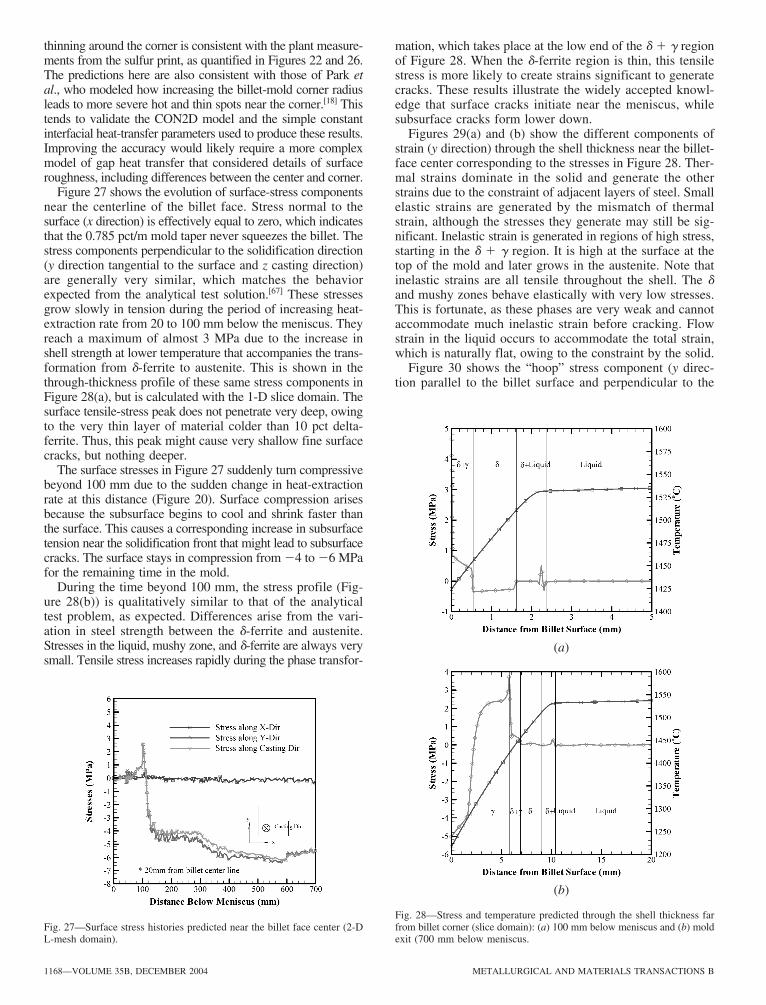


![FINITE ELEMENT ANALYSIS OF SHELL STRUCTURES · hemispherical shell considering the introduction of large displacements ... and Shells” by J.N. Reddy [5] is recommended. 3. The Finite](https://static.fdocuments.us/doc/165x107/5b87f3657f8b9a46538cbf6a/finite-element-analysis-of-shell-structures-hemispherical-shell-considering.jpg)


![Thermomechanical behaviour of Functionally Graded Plates ...jcarme.sru.ac.ir/article_1121_abf57aefaf04fa37c23a... · Singh [2] developed a finite element method (FEM) formulations](https://static.fdocuments.us/doc/165x107/5ed902d66714ca7f4768fb0a/thermomechanical-behaviour-of-functionally-graded-plates-singh-2-developed.jpg)