
Thermoeconomic assessment of an absorption refrigeration and hydrogen-fueled diesel power generator...
10
Thermoeconomic assessment of an absorption refrigeration and hydrogen-fueled diesel power generator cogeneration system Mario David Mateus Herrera 1 , Felipe Rau ´ l Ponce Arrieta 2 , Jose ´ Ricardo Sodre ´ * Pontifical Catholic University of Minas Gerais, Department of Mechanical Engineering, Av. Dom Jose ´ Gaspar, 500, 30535-901 Belo Horizonte, MG, Brazil article info Article history: Received 13 October 2013 Received in revised form 3 January 2014 Accepted 7 January 2014 Available online 1 February 2014 Keywords: Hydrogen Thermoeconomic assessment Diesel engine Ammoniaewater absorption refrig- eration system abstract The thermoeconomic assessment of a cogeneration application that uses a reciprocating diesel engine and an ammoniaewater absorption refrigeration system for electrical power and cold production from hydrogen as fuel is presented. The purpose of the assessment is to get both exergetic and exergoeconomic costs of the cogeneration plant products at different load conditions and concentrations of hydrogenediesel oil blends. The exhaust gas of the reciprocating diesel engine is used as an energy source for an ammoniaewater absorption refrigeration system. The reciprocating diesel engine was simulated using the Gate Cycleä software, and the ammoniaewater absorption refrigeration system simulation and the thermoeconomic assessment were carried out using the Engineering Equation Solver software (EES). The results show that engine combustion is the process of higher exergy destruction in the cogeneration system. Increased hydrogen concentration in the fuel increases the system exergetic efficiency for all load conditions. Exergy destruction in the components of the ammoniaewater absorption refrigeration system is increased with increasing load due to the rise of heat transfer. At intermediate and high loads energy efficiency is increased in the power system, and low values of unit exergetic cost and competitive specific exergoeconomic costs are noticed. The cogeneration system operation at intermediate and high engine loads was proven to be feasible. Copyright ª 2014, Hydrogen Energy Publications, LLC. Published by Elsevier Ltd. All rights reserved. 1. Introduction Cogeneration plants with reciprocating engines are widely used because of their cost effectiveness, mobility and high efficiency. Reciprocating diesel engines have historically been the most popular type of thermal engine for small and large power generation [1].Cogeneration plants with reciprocating engines had been studied by several authors [2e5]. The objective of this work is to perform a thermoeconomic * Corresponding author. Tel.: þ55 31 3319 4911; fax: þ55 31 3319 4910. E-mail addresses: [email protected] (M.D.M. Herrera), [email protected] (F.R.P. Arrieta), [email protected], [email protected] (J.R. Sodre ´). 1 Tel.: þ55 31 3319 4910. 2 Tel.: þ55 31 9614 5380; fax: þ55 31 3319 4910. Available online at www.sciencedirect.com ScienceDirect journal homepage: www.elsevier.com/locate/he international journal of hydrogen energy 39 (2014) 4590 e4599 0360-3199/$ e see front matter Copyright ª 2014, Hydrogen Energy Publications, LLC. Published by Elsevier Ltd. All rights reserved. http://dx.doi.org/10.1016/j.ijhydene.2014.01.028
-
Upload
jose-ricardo -
Category
Documents
-
view
224 -
download
0
Transcript of Thermoeconomic assessment of an absorption refrigeration and hydrogen-fueled diesel power generator...

ww.sciencedirect.com
i n t e rn a t i o n a l j o u r n a l o f h y d r o g e n en e r g y 3 9 ( 2 0 1 4 ) 4 5 9 0e4 5 9 9
Available online at w
ScienceDirect
journal homepage: www.elsevier .com/locate/he
Thermoeconomic assessment of an absorptionrefrigeration and hydrogen-fueled diesel powergenerator cogeneration system
Mario David Mateus Herrera 1, Felipe Raul Ponce Arrieta 2,Jose Ricardo Sodre*
Pontifical Catholic University of Minas Gerais, Department of Mechanical Engineering, Av. Dom Jose Gaspar, 500,
30535-901 Belo Horizonte, MG, Brazil
a r t i c l e i n f o
Article history:
Received 13 October 2013
Received in revised form
3 January 2014
Accepted 7 January 2014
Available online 1 February 2014
Keywords:
Hydrogen
Thermoeconomic assessment
Diesel engine
Ammoniaewater absorption refrig-
eration system
* Corresponding author. Tel.: þ55 31 3319 49E-mail addresses: mario_mateus_h@hotm
[email protected] (J.R. Sodre).1 Tel.: þ55 31 3319 4910.2 Tel.: þ55 31 9614 5380; fax: þ55 31 3319 4
0360-3199/$ e see front matter Copyright ªhttp://dx.doi.org/10.1016/j.ijhydene.2014.01.0
a b s t r a c t
The thermoeconomic assessment of a cogeneration application that uses a reciprocating
diesel engine and an ammoniaewater absorption refrigeration system for electrical power
and cold production from hydrogen as fuel is presented. The purpose of the assessment is
to get both exergetic and exergoeconomic costs of the cogeneration plant products at
different load conditions and concentrations of hydrogenediesel oil blends. The exhaust
gas of the reciprocating diesel engine is used as an energy source for an ammoniaewater
absorption refrigeration system. The reciprocating diesel engine was simulated using the
Gate Cycle� software, and the ammoniaewater absorption refrigeration system simulation
and the thermoeconomic assessment were carried out using the Engineering Equation
Solver software (EES). The results show that engine combustion is the process of higher
exergy destruction in the cogeneration system. Increased hydrogen concentration in the
fuel increases the system exergetic efficiency for all load conditions. Exergy destruction in
the components of the ammoniaewater absorption refrigeration system is increased with
increasing load due to the rise of heat transfer. At intermediate and high loads energy
efficiency is increased in the power system, and low values of unit exergetic cost and
competitive specific exergoeconomic costs are noticed. The cogeneration system operation
at intermediate and high engine loads was proven to be feasible.
Copyright ª 2014, Hydrogen Energy Publications, LLC. Published by Elsevier Ltd. All rights
reserved.
1. Introduction
Cogeneration plants with reciprocating engines are widely
used because of their cost effectiveness, mobility and high
11; fax: þ55 31 3319 4910.ail.com (M.D.M. Herrera)
910.2014, Hydrogen Energy P28
efficiency. Reciprocating diesel engines have historically been
the most popular type of thermal engine for small and large
power generation [1].Cogeneration plants with reciprocating
engines had been studied by several authors [2e5]. The
objective of this work is to perform a thermoeconomic
, [email protected] (F.R.P. Arrieta), [email protected],
ublications, LLC. Published by Elsevier Ltd. All rights reserved.

i n t e r n a t i o n a l j o u r n a l o f h y d r o g e n en e r g y 3 9 ( 2 0 1 4 ) 4 5 9 0e4 5 9 9 4591
assessment of a cogeneration system for production of elec-
tric power and cold at different loads of a diesel power
generator fueled by blends of diesel oil and hydrogen at
different concentrations. The purpose of the assessment is to
get both exergetic and exergoeconomic costs of the cogene-
ration system. The engine exhaust gas is used as an energy
source to produce cold in an ammoniaewater absorption
refrigeration system.
The energy recovery from the diesel engine exhaust gas in
the generator of the absorption refrigeration system improves
fuel utilization efficiency. A similar quantity of thermal energy
could be recovered from the engine coolant. The fundamental
differences between these waste energy sources are the
temperature of the heating fluid and their fluid flow rate. The
temperature of the engine exhaust gas can be several hundred
degrees, but the temperature of engine coolant is much lower
and usually restricted to a maximum temperature close to
110 �C. The performance of the coolant-driven system is
limited by the coolant flow rates; however, it would be
possible to utilize the thermal energy as a source for providing
domestic hot water [6].
Hydrogen (H2) is one of the most promising alternative
fuels [7] due to its clean burning characteristics and high
performance delivery [8]. The use of hydrogen as a fuel in
internal combustion engines reduces pollutants such as car-
bon monoxide and unburned hydrocarbons. If the generation
of hydrogen fuel can be done using renewable energy sources,
and other challenges such as storage and transport of
hydrogen can be solved, the replacing of fossil fuels with
renewable sources using hydrogen as an energy carrier may
help to mitigate the effects of carbon dioxide emissions [9].
However, hydrogen cannot be used as a sole fuel in a
compression ignition engine because the compression tem-
perature is not enough to initiate the combustion due to its
higher self-ignition temperature as required in the compres-
sion ignition engine [8]. So, hydrogen has can be seen as the
perfect fuel for energy systems. It can be used in combustion
devices or fuel cells without any carbon emissions, and min-
imal emission of other pollutant gases.
The use of hydrogen in a pre-mixed homogeneous charge
compression ignition engine presents ignition timing control
problems, but the use of pre-mixed hydrogen in the intake air
of conventional compression ignition engines does not pre-
sent this problem. The direct injection of hydrogen allows for
much better control of engine operation. Consideration must
be given to the control of injection timing and duration, as
these variables heavily influence factors such as the rate of
pressure rise and maximum combustion pressure. Direct in-
jection offers the possibility to control and limit excessive
mechanical load [9].
In a dual fuel engine, the main fuel is inducted or injected
into the intake air stream with combustion initiated by diesel
oil. Most of the energy is obtained from diesel oil, while the
rest of the energy is supplied by hydrogen. The hydrogen
operated dual fuel engine has the property to operate with
lean mixtures at part load and no load, which results in NOx
reduction, with an increase in thermal efficiency, thereby
reducing fuel consumption [8].
Some authors studied the effects of hydrogen blends at
different proportions on combustion and emissions of diesel
engines. Gatts et al. [10] performed an experiment of incom-
plete combustion of gaseous fuels of a heavy-duty diesel en-
gine fueled by hydrogen and natural gas.Wu andWu [11] used
the Taniguchi method to determine the optimal combinations
of concentrations for a diesel engine blend using H2 and
cooled exhaust gas recirculation (EGR) at the inlet port. It was
concluded that hydrogenediesel co-fueling solved the draw-
back of lean operation of hydrocarbon fuels such as diesel oil,
which is hard to ignite and results in reduced power output, by
reducing misfires, improving emissions, performance, fuel
economy, and also combustion noise [12]. Due to enhanced
combustion, cylinder gas temperature is high with hydrogen
fuel enrichment [13].
The relatively low exhaust temperature produced by diesel
engines can make them unattractive for cogeneration pur-
poses, but the waste heat from the engine, when coupled with
an absorption refrigeration unit, can be used for environment
control purposes, or for improving the efficiency of the pro-
cess [6]. Diesel engines have not generally been adopted for
cogeneration systems because a substantial fraction of the
heat rejected is at too low temperature for any recovery
compared with other cycles. Heat rates are relatively low for a
diesel engine compared to a steam or gas turbine, but diesel
engines are better suited to a high ratio of electric power to
steam. A stationary power plant does not suffer some of the
limitations of a mobile power plant. In the former, it would be
possible to incorporate equipment to overcome some of the
stated difficulties [6].
On the other hand, absorption refrigeration technology has
been used for over 100 years, and today the technology has
made it an economic and effective alternative. The electricity
cost and environmental problems have made this cycle
attractive for residential and industrial applications. In an
absorption refrigeration system, a binary solution consists of a
refrigerant and an absorbent as the working fluids. The per-
formance of an absorption refrigeration system is critically
dependent on the chemical and thermodynamic properties of
the working fluid [14].
Absorption refrigeration systems differ from vapor
compression refrigeration systems due to the utilization of
thermal energy source instead of electric energy. The basic
components of an ammoniaewater absorption refrigeration
system are an absorber, a pump, a condenser, an evaporator,
and a generator. The purpose of the generator is to provide a
stream of vapor solution and a weak solution of refrigerant;
the purpose of the pump is to raise the pressure of the strong
solution leaving the absorber. The evaporator, the condenser,
and the absorber have the purpose to transfer or reject energy
from the vapor stream [15]. The evaporation process in the
absorption refrigeration system is important because in the
case of binary mixtures such as ammoniaewater, vapor pu-
rification is required.
The absorption refrigeration system is of high interest
because it can produce higher cooling capacity than the vapor
compressor system and it can be powered by other sources of
energy (like waste heat from engine exhaust gas) rather than
electricity. This system does not deplete the ozone layer and,
hence, it poses no danger to the environment. Experimental
studies of absorption refrigeration systems have shown that a
high temperature heat source has not been utilized efficiently.
i n t e rn a t i o n a l j o u r n a l o f h y d r o g e n en e r g y 3 9 ( 2 0 1 4 ) 4 5 9 0e4 5 9 94592
Recent analyses included the second law of Thermodynamics
to provide better understanding of the thermal performance
characteristics of each of the system components. This facil-
itates the detection of a component with high energy and
exergy dissipation or irreversible losses [16].
2. Cogeneration system description
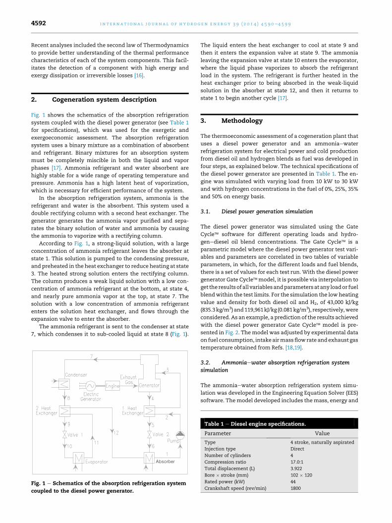
Fig. 1 shows the schematics of the absorption refrigeration
system coupled with the diesel power generator (see Table 1
for specifications), which was used for the exergetic and
exergoeconomic assessment. The absorption refrigeration
system uses a binary mixture as a combination of absorbent
and refrigerant. Binary mixtures for an absorption system
must be completely miscible in both the liquid and vapor
phases [17]. Ammonia refrigerant and water absorbent are
highly stable for a wide range of operating temperature and
pressure. Ammonia has a high latent heat of vaporization,
which is necessary for efficient performance of the system.
In the absorption refrigeration system, ammonia is the
refrigerant and water is the absorbent. This system used a
double rectifying column with a second heat exchanger. The
generator generates the ammonia vapor purified and sepa-
rates the binary solution of water and ammonia by causing
the ammonia to vaporize with a rectifying column.
According to Fig. 1, a strong-liquid solution, with a large
concentration of ammonia refrigerant leaves the absorber at
state 1. This solution is pumped to the condensing pressure,
and preheated in the heat exchanger to reduce heating at state
3. The heated strong solution enters the rectifying column.
The column produces a weak liquid solution with a low con-
centration of ammonia refrigerant at the bottom, at state 4,
and nearly pure ammonia vapor at the top, at state 7. The
solution with a low concentration of ammonia refrigerant
enters the solution heat exchanger, and flows through the
expansion valve to enter the absorber.
The ammonia refrigerant is sent to the condenser at state
7, which condenses it to sub-cooled liquid at state 8 (Fig. 1).
Fig. 1 e Schematics of the absorption refrigeration system
coupled to the diesel power generator.
The liquid enters the heat exchanger to cool at state 9 and
then it enters the expansion valve at state 9. The ammonia
leaving the expansion valve at state 10 enters the evaporator,
where the liquid phase vaporizes to absorb the refrigerant
load in the system. The refrigerant is further heated in the
heat exchanger prior to being absorbed in the weak-liquid
solution in the absorber at state 12, and then it returns to
state 1 to begin another cycle [17].
3. Methodology
The thermoeconomic assessment of a cogeneration plant that
uses a diesel power generator and an ammoniaewater
refrigeration system for electrical power and cold production
from diesel oil and hydrogen blends as fuel was developed in
four steps, as explained below. The technical specifications of
the diesel power generator are presented in Table 1. The en-
gine was simulated with varying load from 10 kW to 30 kW
and with hydrogen concentrations in the fuel of 0%, 25%, 35%
and 50% on energy basis.
3.1. Diesel power generation simulation
The diesel power generator was simulated using the Gate
Cycle� software for different operating loads and hydro-
genediesel oil blend concentrations. The Gate Cycle� is a
parametric model where the diesel power generator test vari-
ables and parameters are correlated in two tables of variable
parameters, in which, for the different loads and fuel blends,
there is a set of values for each test run. With the diesel power
generator Gate Cycle�model, it is possible via interpolation to
get the resultsofall variablesandparametersatany loador fuel
blendwithin the test limits. For the simulation the lowheating
value and density for both diesel oil and H2, of 43,000 kJ/kg
(835.3kg/m3)and119,961kJ/kg (0.081kg/m3), respectively,were
considered.As an example, a prediction of the results achieved
with the diesel power generator Gate Cycle� model is pre-
sented in Fig. 2. Themodel was adjusted by experimental data
on fuel consumption, intakeairmassflowrate andexhaust gas
temperature obtained from Refs. [18,19].
3.2. Ammoniaewater absorption refrigeration systemsimulation
The ammoniaewater absorption refrigeration system simu-
lation was developed in the Engineering Equation Solver (EES)
software. Themodel developed includes themass, energy and
Table 1 e Diesel engine specifications.
Parameter Value
Type 4 stroke, naturally aspirated
Injection type Direct
Number of cylinders 4
Compression ratio 17.0:1
Total displacement (L) 3.922
Bore � stroke (mm) 102 � 120
Rated power (kW) 44
Crankshaft speed (rev/min) 1800

Fig. 2 e Sample of the diesel power generator simulation results in the Gate Cycle software.
i n t e r n a t i o n a l j o u r n a l o f h y d r o g e n en e r g y 3 9 ( 2 0 1 4 ) 4 5 9 0e4 5 9 9 4593
entropy balances in each component of the system. As a
result, the irreversibilities of the components, the efficiency of
the generator, the heat transfer in the condenser, evaporator,
absorber and heat exchanger, and the pump power are
calculated, as well as the coefficient of performance (COP) of
the system. The ammoniaewater absorption refrigeration
system data used in the simulation are presented in Table 2. A
detailed description of the simulation model can be found in
Herrera [20].
3.3. Cogeneration plant performance characterization
The performance index used for characterization of the
cogeneration system is the exergetic efficiency of the diesel
power generator. In addition, for the ammoniaewater ab-
sorption refrigeration system, the parameters analyzed are
coefficient of performance, exergetic efficiencies of the whole
system and the generator alone, and the exergy destruction.
Table 2 eAbsorption refrigeration system data usedfor simulation.
Parameter Value
Reference temperature (�C) 30
Condenser temperature (�C) 37
Generator temperature (�C) 127
Evaporator temperature (�C) 7
Absorber temperature (�C) 38
Reference pressure (kPa) 101.32
System high pressure (kPa) 1378.95
System low pressure (kPa) 206.84
Pump efficiency (%) 75
The specific fuel consumption of the diesel engine (SFC, in
kg/kWh), given by the ratio between the total fuel mass flow,
diesel oil plus hydrogen ðm$ fuel in kg=hÞ and the output power
ðW$
in kWÞ, is expressed by the following equation:
SFC ¼ m$
fuel
W$ (1)
The exergetic efficiency of the diesel power generator (hexDE)
is given by the ratio between the output power from the diesel
power generator and the total exergy supplied with the fuel
ðE$
xfuel; in kWÞ. This includes the diesel mass flow
ðm$ D; in kg=sÞ and its specific exergy (exD, in kJ/kg), and the
hydrogen mass flow ðm$ H2; in kg=sÞ and its specific exergy
ðexH2; in kJ=kgÞ. The exergetic efficiency hex
DE is calculated as:
hexDE ¼ W
$
E$
xfuel
¼ W$
m$
D$exD þm$
H2$exH2
(2)
The coefficient of performance (COP) of the ammonia-
water absorption refrigeration system is given by the ratio
between the total cold produced ðQ$
C; in kWÞ and the energy
input from the exhaust gas ðQ$
G; in kWÞ plus the power
consumed by the pump ðW$
P; in kWÞ. The total cold produced
is computed considering the refrigerant mass flow
ðm$ R; in kg=sÞ and its specific enthalpy at the inlet (h10, in kJ/
kg) and the outlet (h11, in kJ/kg) of the evaporator (see Fig. 1).
The exhaust gas energy considers the gas mass flow
ðm$ G; in kg=sÞ and its specific enthalpy (hG, in kJ/kg). The
power consumed by the pump considers the refrigerant mass
flow and the specific enthalpies at the pump inlet (h1, in kJ/
kg) and outlet (h12, in kJ/kg) (see Fig. 1). The COP is calculated
by the equation:

i n t e rn a t i o n a l j o u r n a l o f h y d r o g e n en e r g y 3 9 ( 2 0 1 4 ) 4 5 9 0e4 5 9 94594
COP ¼ QC$ $ ¼ h11 � h10�
$ $� (3)
$
QG þWP mG=mR :hG þ ðh2 � h1Þ
The exergetic efficiency of the ammoniaewater absorption
refrigeration system (hexARS) is given by the ratio between the
total exergy of the produced cold ðE$
xC; in kWÞ, the total
exergy of the exhaust gas at the refrigerator system generator
inlet ðE$
xG; in kWÞ and the work consumed by the pump. The
total exergy of the produced cold is computed considering the
refrigerant mass flow and its specific exergy at the evaporator
inlet (ex10, in kJ/kg) and the outlet (ex11, in kJ/kg) (see Fig. 1).
The total exergy of the exhaust gas considers the gas mass
flow and its specific exergy (exG, in kJ/kg). The exergetic effi-
ciency of the absorption refrigeration system is computed by:
hexARS ¼ E
$
xC
E$
xG þW$
P
¼ ex11 � ex10�m$
G=m$
R
�$exG þ ðh2 � h1Þ
(4)
The exergetic efficiency of the refrigeration system gener-
ator ðhexARSG
Þ is givenby the ratio between the exhaust gas exergy
and the exergy gain by the mass flows in the generator
ðm$ 3;m$
4;m$
7; all in kg=sÞ (Fig. 1) due to their respective specific
exergies (ex3, ex4, ex7, kJ/kg), and it is computedby the equation:
hexARSG
¼ m$
4$ex4 þm$
7$ex7 �m$
3$ex3
E$
xG
(5)
The exergy destruction ðI$
; in kWÞ of each component (i) in
the absorption refrigeration system is computed using the
Fig. 3 e CHP plant pro
Guy-Stodola theorem, considering the generated entropy
ðS$
gen; in kW=KÞ and the assumed dead state temperature
(T0 ¼ 300 K) by the equation:
I$
i ¼ T0$S$
gen (6)
The generated entropy is computed from application of the
entropy balance at steady state in each component of the
absorption refrigeration system.
3.4. Cogeneration plant thermoeconomic assessment
In order to perform the thermoeconomic assessment, it is
useful to define a productive or causal structure, the coun-
terpart to the physical structure used to calculate the system
energy and the exergy flows [21]. For the thermal scheme of
the cogeneration plant presented in Fig. 1, the productive
structure developed is shown in Fig. 3, which is a schematic
representation of the plant based on the Fuel-Product concept.
To calculate the unit exergetic cost and the specific exer-
goeconomic cost, a model based on application of the Struc-
tural Theory of Thermoeconomic analysis was developed [22].
The thermoeconomicmodel is amathematical representation
of the productive structure of a system [23]. Exergy balances
were applied to each system component, as shown in Fig. 1.
The aim is to calculate the unit exergetic cost and the specific
exergoeconomic cost of each stream in the productive struc-
ture, mainly the net electrical power and cold produced by the
system at the different load and fuel mixtures simulated. The
ductive structure.

Table 4 e Considered investment cost.
Equipment Components US$
Diesel power generator Engine and its auxiliaries 12,555.00
Electric generator 1395.00
Absorption refrigeration
system
Generator 2441.20
Condenser 2082.20
Evaporator 2527.00
Absorber 2986.88
Heat exchanger 1 1163.16
Heat exchanger 2 1163.16
Valve 1 300.00
Valve 2 300.00
Pump 653.40
i n t e r n a t i o n a l j o u r n a l o f h y d r o g e n en e r g y 3 9 ( 2 0 1 4 ) 4 5 9 0e4 5 9 9 4595
unit exergetic cost (k*) is defined by the correlation between
the total stream exergy cost ðE$
x�; in kWÞ and the total stream
exergy ðE$
x; in kWÞ. The specific exergoeconomic cost (c*) is
defined by the correlation between the stream exer-
goeconomic cost ðC$ �; R and the total stream exergy. That is:
k� ¼ E$
x�
E$
x(7)
c� ¼ C�
E$
x(8)
The assumptions for the thermoeconomic assessment are
shown in Table 3. The investment cost of the cogeneration
plant is presented inTable4 [24]. Thediesel oil price considered
in the calculations was 0.4 R$/L. This is the value of the
commercialization price for thermal power generation estab-
lished by the Brazilian Ministry of Finance [25]. The hydrogen
price used was 1.8 US$/g referred by the Global Hydrogen
Incorporated in May 2012 [26]. More details about the ther-
moeconomic assessment can be consulted in Herrera [20].
3.5. Model integration
The input data from the engine used for the simulation in the
Gate Cycle� software is shown by Table 5. The data includes
the engine exhaust gas temperature, diesel oil and hydrogen
mass flow rates at different engine loads and hydrogen con-
centrations. Additional data used for the Gate Cycle� simu-
lation is presented in Table 6. The results from the Gate
Cycle� calculations are:
- The mass, energy, and entropy balances, as shown by
Fig. 2;
- The estimated chemical composition of the exhaust gas;
- The mechanical power, the electric power, the specific fuel
consumption (Eq. (1)) and the exergetic efficiency (Eq. (2)).
All this information can be obtained with the Gate Cycle�model, via interpolation, at any engine load between 0 kWand
30 kW and for any hydrogen concentration in the range from
0% to 50%. The estimated chemical composition, temperature,
pressure, mass flow rate, specific enthalpy and specific en-
tropy are used for calculation of the specific and total exergy of
the engine exhaust gas. The methodology employed for
calculation of the exhaust gas exergy is that presented by
Lozano and Valero [27].
The engine exhaust gas exergy is the same adopted at the
inlet of the absorption refrigeration system. This information
together with the one shown in Table 2 are the input data for
Table 3 e Assumptions for exergoeconomiccalculations.
Parameter Value
Annual operation time (h) 6000
Interest rate per year (%) 10
Life time (year) 20
Maintenance factor per year (%) 5
Amortization factor per year (%) 12
the absorption refrigeration system simulation model elabo-
rated in the EES software. The output data obtained with this
model include mass, energy, entropy and exergy balances for
each equipment of the refrigeration system. Temperature,
pressure, specific enthalpy, specific entropy, specific exergy
and mass flow rate are also obtained for each stream of the
system shown in Fig. 1. Other calculated data are: heat
transfer rate at low temperature (produced cold) and high
temperature (dissipated heat), pump power, COP (Eq. (3)) and
the exergetic efficiency (Eq. (4)) of the refrigeration system. All
information calculated by the EES absorption refrigeration
system model was obtained at any engine load between 0 kW
and 30 kW, and hydrogen concentrations in the range from 0%
to 50%.
The results from the Gate Cycle� model used for the
thermoeconomic assessment are: mechanical and electric
power, total fuel exergy, exergy variation of the engine cooling
water flow and total exergy of the exhaust gas. The results
from the EES absorption refrigeration system simulation
model used for the thermoeconomic assessment are: total
exergy of each stream of the system, total exergy of the heat
transfer rate and pump power. The information presented in
Tables 3and 4 complement the input data used for the ther-
moeconomic assessment. The results of the thermoeconomic
calculations are: fuel, product, exergy destruction, unit exergy
consumption and exergy efficiency of all components, and
unit exergetic cost and exergoeconomic cost for each stream
shown in Fig. 3. The unit exergetic cost and the exer-
goeconomic cost of streams 20 (produced electric power) and
50 (cold of the cogeneration system) are very influential in the
results.
4. Results and discussion
The effect of hydrogen concentration in the fuel on the engine
exergetic efficiency with varying load is illustrated in Fig. 4.
When engine load and hydrogen concentration in the fuel are
increased the engine exergetic efficiency is also increased.
That is a direct consequence of the best fuel conversion effi-
ciency achieved. The diesel engine used in the analysis pro-
vides a significant decrease of specific fuel consumption until
about half of its rated power (44 kW), then the SFC calculated
from the data of Table 5 only shows a slight reduction for
higher load power. That is the reason for the marked increase
of the exergetic efficiency observed until around 20 kW of load

Table 5 e Experimental test results [20].
Engineload(kW)
100% diesel oil 75% diesel oil þ 25% H2 65% diesel oil þ 35% H2 50% diesel oil þ 50% H2
Exhaustgas
temp (�C)
Dieseloil flow
rate (kg/h)
Exhaustgas
temp (�C)
Dieseloil flow
rate (kg/h)
H2 flowrate(kg/h)
Exhaustgas
temp (�C)
Diesel oilflow rate(kg/h)
H2 flowrate(kg/h)
Exhaustgas temp
(�C)
Diesel oilflow rate(kg/h)
H2 flowrate(kg/h)
0 143.01 1.91 135.22 1.91 e 145.52 1.77 e 136.45 1.83 e
10 224.09 3.37 210.99 3.21 0.317 211.54 3.09 0.444 207.64 3.02 0.634
20 324.17 5.17 300.48 4.70 0.472 296.72 4.64 0.661 297.22 4.22 0.944
30 447.79 7.15 411.77 6.37 0.656 409.21 6.37 0.919 409.40 5.99 1.312
Fig. 4 e Variation of engine exergetic efficiency with load
power and hydrogen concentration in the fuel.
i n t e rn a t i o n a l j o u r n a l o f h y d r o g e n en e r g y 3 9 ( 2 0 1 4 ) 4 5 9 0e4 5 9 94596
power, with more modest increase of the exergetic efficiency
for higher loads (Fig. 4).
In Fig. 5 it is observed that the absorption refrigeration
system exergetic efficiency is decreased with increasing en-
gine load, which is a result from the rise of the irreversibilities
in the refrigeration system components caused by the in-
crease of heat transfer due to higher engine exhaust gas
temperature [18]. On the other hand, the use of hydrogen in
the fuel increases the refrigeration system exergetic effi-
ciency. The increased engine exhaust temperature achieved
with increasing load [18] producesmore cold in the absorption
refrigeration system (Fig. 6). A constant COP of 0.605 was ob-
tained for all load range investigated.
In Fig. 7, the exergetic efficiency of the absorption refrig-
eration system generator is shown for diesel oil and for the
fuel with 35% of hydrogen concentration. It is observed a
reduction of the exergetic efficiency of the refrigeration sys-
tem generatorwith the increase of engine load. That is a result
of higher entropy generation (or irreversibilities) caused by
heat transfer in the generator at higher temperature differ-
ence between the engine exhaust gas and the refrigeration
system working fluid.
The exergy destruction (or irreversibilities) in the refriger-
ation system components is shown by Fig. 8 for different en-
gine loads using diesel oil as fuel. The increase of exergy
destructionwith engine load finds the same explanation given
for the decreased exergetic efficiency of a component (see
Fig. 7). The highest exergy destructions are noticed in the
evaporator and the absorber. These trends have been
observed for any concentration of the ammoniaewater pair.
The unit exergetic cost of the produced cold is shown by
Fig. 9. For the load range investigated the unit exergetic cost is
lower than when hydrogen is used in the fuel, in comparison
with the use of diesel oil only. On the other hand, the positive
effect of the increased engine efficiency with increasing en-
gine load [19] is not enough to cancel the negative effect of the
Table 6 e Additional data for simulation.
Parameter Value
Air inlet temperature (�C) 30.00
Diesel oil inlet temperature (�C) 30.00
Cooling water inlet temperature (�C) 80.00
Atmospheric pressure (kPa) 101.32
Engine shaft speed (rev/min) 1800.00
Fractional mechanical losses 0.05
Fractional electrical losses 0.05
Power factor 0.80
increased irreversibilities due to the higher temperature dif-
ferences in the refrigeration system component resulted from
the increased engine exhaust gas temperature [18]. As a
consequence, the unit exergetic cost of the produced cold is
increased with increasing engine load.
As it is seen in Fig. 10, the unit exergetic cost of the pro-
duced power is reduced with increasing engine load and
Fig. 5 e Variation of absorption refrigeration system
exergetic efficiency with engine load power and hydrogen
concentration in the fuel.
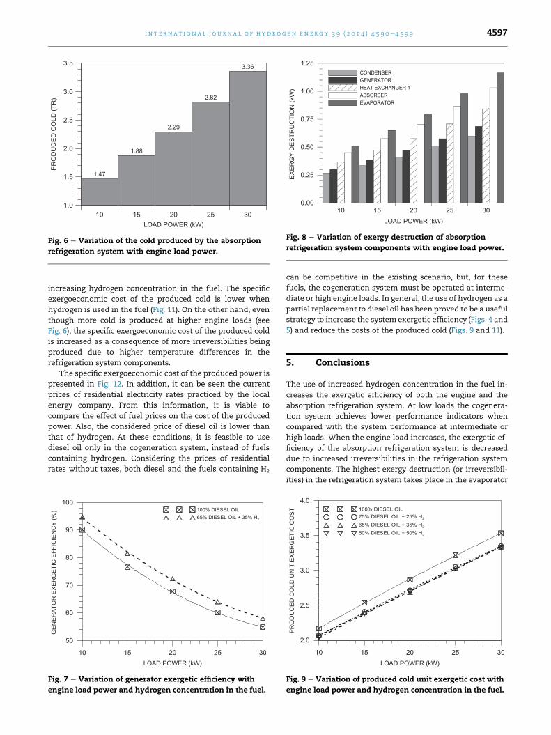
Fig. 6 e Variation of the cold produced by the absorption
refrigeration system with engine load power.
Fig. 8 e Variation of exergy destruction of absorption
refrigeration system components with engine load power.
i n t e r n a t i o n a l j o u r n a l o f h y d r o g e n en e r g y 3 9 ( 2 0 1 4 ) 4 5 9 0e4 5 9 9 4597
increasing hydrogen concentration in the fuel. The specific
exergoeconomic cost of the produced cold is lower when
hydrogen is used in the fuel (Fig. 11). On the other hand, even
though more cold is produced at higher engine loads (see
Fig. 6), the specific exergoeconomic cost of the produced cold
is increased as a consequence of more irreversibilities being
produced due to higher temperature differences in the
refrigeration system components.
The specific exergoeconomic cost of the produced power is
presented in Fig. 12. In addition, it can be seen the current
prices of residential electricity rates practiced by the local
energy company. From this information, it is viable to
compare the effect of fuel prices on the cost of the produced
power. Also, the considered price of diesel oil is lower than
that of hydrogen. At these conditions, it is feasible to use
diesel oil only in the cogeneration system, instead of fuels
containing hydrogen. Considering the prices of residential
rates without taxes, both diesel and the fuels containing H2
Fig. 7 e Variation of generator exergetic efficiency with
engine load power and hydrogen concentration in the fuel.
can be competitive in the existing scenario, but, for these
fuels, the cogeneration system must be operated at interme-
diate or high engine loads. In general, the use of hydrogen as a
partial replacement to diesel oil has been proved to be a useful
strategy to increase the system exergetic efficiency (Figs. 4 and
5) and reduce the costs of the produced cold (Figs. 9 and 11).
5. Conclusions
The use of increased hydrogen concentration in the fuel in-
creases the exergetic efficiency of both the engine and the
absorption refrigeration system. At low loads the cogenera-
tion system achieves lower performance indicators when
compared with the system performance at intermediate or
high loads. When the engine load increases, the exergetic ef-
ficiency of the absorption refrigeration system is decreased
due to increased irreversibilities in the refrigeration system
components. The highest exergy destruction (or irreversibil-
ities) in the refrigeration system takes place in the evaporator
Fig. 9 e Variation of produced cold unit exergetic cost with
engine load power and hydrogen concentration in the fuel.
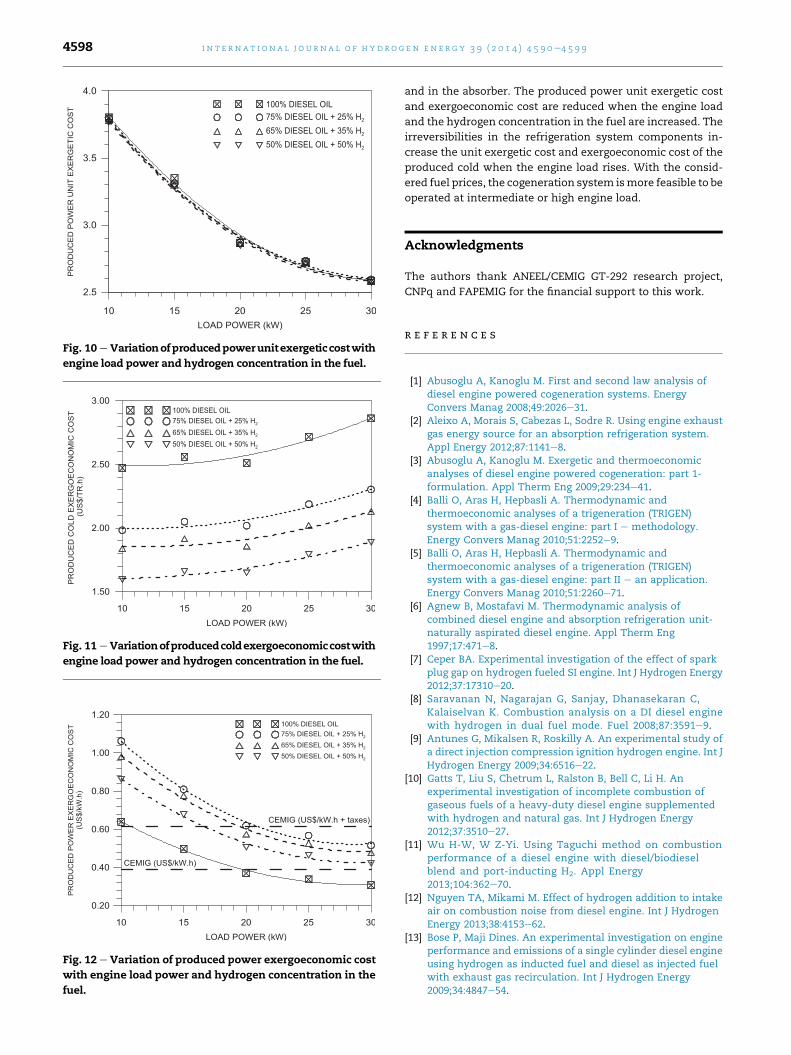
Fig. 11 e Variationofproducedcoldexergoeconomiccostwith
engine load power and hydrogen concentration in the fuel.
Fig. 12 e Variation of produced power exergoeconomic cost
with engine load power and hydrogen concentration in the
fuel.
Fig. 10 e Variationofproducedpowerunitexergeticcostwith
engine load power and hydrogen concentration in the fuel.
i n t e rn a t i o n a l j o u r n a l o f h y d r o g e n en e r g y 3 9 ( 2 0 1 4 ) 4 5 9 0e4 5 9 94598
and in the absorber. The produced power unit exergetic cost
and exergoeconomic cost are reduced when the engine load
and the hydrogen concentration in the fuel are increased. The
irreversibilities in the refrigeration system components in-
crease the unit exergetic cost and exergoeconomic cost of the
produced cold when the engine load rises. With the consid-
ered fuel prices, the cogeneration system ismore feasible to be
operated at intermediate or high engine load.
Acknowledgments
The authors thank ANEEL/CEMIG GT-292 research project,
CNPq and FAPEMIG for the financial support to this work.
r e f e r e n c e s
[1] Abusoglu A, Kanoglu M. First and second law analysis ofdiesel engine powered cogeneration systems. EnergyConvers Manag 2008;49:2026e31.
[2] Aleixo A, Morais S, Cabezas L, Sodre R. Using engine exhaustgas energy source for an absorption refrigeration system.Appl Energy 2012;87:1141e8.
[3] Abusoglu A, Kanoglu M. Exergetic and thermoeconomicanalyses of diesel engine powered cogeneration: part 1-formulation. Appl Therm Eng 2009;29:234e41.
[4] Balli O, Aras H, Hepbasli A. Thermodynamic andthermoeconomic analyses of a trigeneration (TRIGEN)system with a gas-diesel engine: part I e methodology.Energy Convers Manag 2010;51:2252e9.
[5] Balli O, Aras H, Hepbasli A. Thermodynamic andthermoeconomic analyses of a trigeneration (TRIGEN)system with a gas-diesel engine: part II e an application.Energy Convers Manag 2010;51:2260e71.
[6] Agnew B, Mostafavi M. Thermodynamic analysis ofcombined diesel engine and absorption refrigeration unit-naturally aspirated diesel engine. Appl Therm Eng1997;17:471e8.
[7] Ceper BA. Experimental investigation of the effect of sparkplug gap on hydrogen fueled SI engine. Int J Hydrogen Energy2012;37:17310e20.
[8] Saravanan N, Nagarajan G, Sanjay, Dhanasekaran C,Kalaiselvan K. Combustion analysis on a DI diesel enginewith hydrogen in dual fuel mode. Fuel 2008;87:3591e9.
[9] Antunes G, Mikalsen R, Roskilly A. An experimental study ofa direct injection compression ignition hydrogen engine. Int JHydrogen Energy 2009;34:6516e22.
[10] Gatts T, Liu S, Chetrum L, Ralston B, Bell C, Li H. Anexperimental investigation of incomplete combustion ofgaseous fuels of a heavy-duty diesel engine supplementedwith hydrogen and natural gas. Int J Hydrogen Energy2012;37:3510e27.
[11] Wu H-W, W Z-Yi. Using Taguchi method on combustionperformance of a diesel engine with diesel/biodieselblend and port-inducting H2. Appl Energy2013;104:362e70.
[12] Nguyen TA, Mikami M. Effect of hydrogen addition to intakeair on combustion noise from diesel engine. Int J HydrogenEnergy 2013;38:4153e62.
[13] Bose P, Maji Dines. An experimental investigation on engineperformance and emissions of a single cylinder diesel engineusing hydrogen as inducted fuel and diesel as injected fuelwith exhaust gas recirculation. Int J Hydrogen Energy2009;34:4847e54.

i n t e r n a t i o n a l j o u r n a l o f h y d r o g e n en e r g y 3 9 ( 2 0 1 4 ) 4 5 9 0e4 5 9 9 4599
[14] Srikhirin P, Aphornratana S, Chungpaibulpatana S. A reviewof absorption refrigeration technologies. Renew SustainEnergy Rev 2001;5:343e72.
[15] Misra R, Sahoo P, Gupta A. Thermoeconomic evaluation andoptimization of an aqua-ammonia vapour-absorptionrefrigeration system. Int J Refrig 2006;29:47e59.
[16] Adewusi S, Zubair S. Second law based thermodynamicanalysis of ammonia-water absorption systems. EnergyConvers Manag 2004;45:2355e69.
[17] Kuehn T, Ramsey J, Threlkeld J. Thermal environmentengineering. 3rd ed. New Jersey: Prentice Hall; 1998.
[18] Justino M, Morais M, Oliveira A, Valente OS, Sodre JR. Fuelconsumption of a diesel engine fuelled with hydrogen,natural gas and diesel blends. SAE Technical Paper; 2012.pp. 1e6. 2012-36-0107.
[19] Morais M, Justino M, Valente OS, Hanriot SM, Sodre JR.Hydrogen impacts on performance and CO2 emissions froma diesel power generator. Int J Hydrogen Energy2013;38:6857e64.
[20] Herrera MDM. Natural gas and hydrogen: evaluation forcogeneration of electricity and cold. M.Sc. Dissertation. BeloHorizonte: Pontifical Catholic University of Minas Gerais;2012 [in Portuguese].
[21] Schwarcz P, Lozano MA, von Spakosvsky MR, Valero A.Diagnostic analysis of PFBC power plant using athermoeconomic methodology. In: Proc.. Of TAIES’97-thermodynamic analysis and improvement of Energy
systems international conference. Beijing: Beijing WorldPublishing Corporation; 1997.
[22] Valero A, Serra L, Lozano MA. Structural theory ofthermoeconomics. In: Proc. of 1993 ASME advanced energysystem division. San Diego: American Society of MechanicalEngineers; 1993.
[23] Serra L, Cuadra CT. Structural theory of thermoeconomics.In: Frangopoulos CA, editor. Encyclopedia of the supportsystems. Oxford: EOLSS Publishers; 2006.
[24] Lima H. Thermoeconomics analysis of absorptionrefrigeration systems with water-lithium bromide pair. PhDThesis. Joao Pessoa: Federal University of Paraiba; 2004 [inPortuguese].
[25] Brazilian Ministry of Finance. Table of maximum retail dieseloil prices. Available in: www.fazenda.gov.br/portugues/legislacao/portarias_inter/2001/anxport198.pdf. [accessed in16.08013].
[26] Global Hydrogen Incorporated. Hydrogen fuel cars &vehicles. Available in: <http://www.hydrogencarsnow.com/blog2/index.php/hydrogen-fuel-production/global-hydrogen-inc-lowers-price-of-hydrogen-to-247-per-gallon/>. [accessed in 16.08.13].
[27] Lozano M, Valero A. Calculation of exergy for substances ofindustrial interesting. Dept. of Thermodynamics and PhysiceChemistry. ETSII. Zaragoza University. Chemical EngineeringMagazine; March, 1986 [in Spanish].