Thermodynamics Fundamentals for Energy Conversion...
24
Sustainable Energy Science and Engineering Center Thermodynamics Fundamentals for Energy Conversion Systems (Continued)
Transcript of Thermodynamics Fundamentals for Energy Conversion...

Sustainable Energy Science and Engineering Center
Thermodynamics Fundamentals for Energy Conversion Systems
(Continued)
Sustainable Energy Science and Engineering Center
Open Brayton Power Cycle
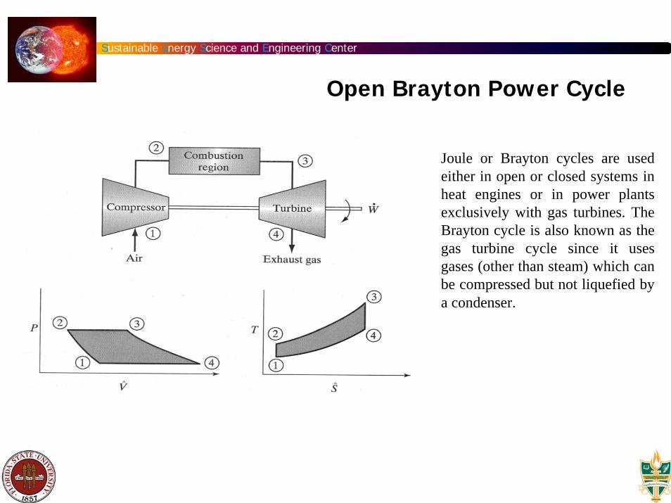
Joule or Brayton cycles are used either in open or closed systems in heat engines or in power plants exclusively with gas turbines. The Brayton cycle is also known as the gas turbine cycle since it uses gases (other than steam) which can be compressed but not liquefied by a condenser.
Sustainable Energy Science and Engineering Center
Open Brayton Power Cycle
The air-standard Brayton cycle is an ideal cycle that approximates the processes incorporated within the standard gas-turbine engine. In the following description of the ideal Brayton cycle, the initial state is taken where atmospheric pressure air enters the inlet of a steady flow compressor. This cycle is shown for constant specific heats on P-v, and T-s diagrams.
Process 1 - 2: an isentropic compression of atmospheric air from the inlet to the compressor to the maximum pressure in the cycle,Process 2-3: a constant-pressure combustion process (heat addition),Process 3-4: an isentropic expansion of the products of combustion from the inlet to the turbine to the exhaust of the turbine at atmospheric pressure,Process 4-1: a constant-pressure heat rejection process until the temperature returns to initial conditions.
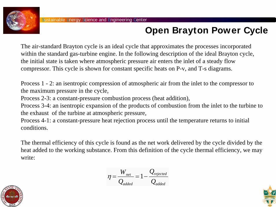
The thermal efficiency of this cycle is found as the net work delivered by the cycle divided by the heat added to the working substance. From this definition of the cycle thermal efficiency, we may write:
η =Wnet
Qadded
=1−Qrejected
Qadded
Sustainable Energy Science and Engineering Center
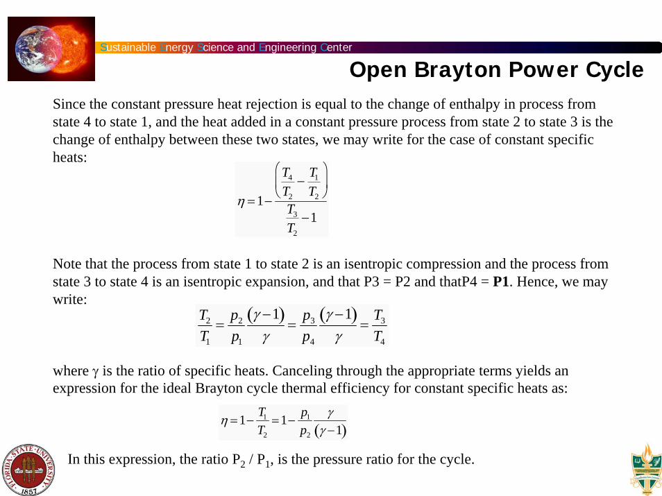
Open Brayton Power CycleSince the constant pressure heat rejection is equal to the change of enthalpy in process from state 4 to state 1, and the heat added in a constant pressure process from state 2 to state 3 is the change of enthalpy between these two states, we may write for the case of constant specific heats:
Note that the process from state 1 to state 2 is an isentropic compression and the process from state 3 to state 4 is an isentropic expansion, and that P3 = P2 and thatP4 = P1. Hence, we may write:
where γ is the ratio of specific heats. Canceling through the appropriate terms yields an expression for the ideal Brayton cycle thermal efficiency for constant specific heats as:
In this expression, the ratio P2 / P1, is the pressure ratio for the cycle.
η =1−
T4
T2
−T1
T2
⎛
⎝ ⎜
⎞
⎠ ⎟
T3
T2
−1
T2
T1
=p2
p1
γ −1( )γ
=p3
p4
γ −1( )γ
=T3
T4
η =1−T1
T2
=1−p1
p2
γγ −1( )
Sustainable Energy Science and Engineering Center
Open Brayton Power Cycle
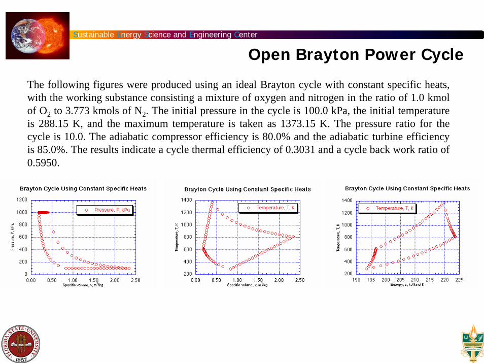
The following figures were produced using an ideal Brayton cycle with constant specific heats, with the working substance consisting a mixture of oxygen and nitrogen in the ratio of 1.0 kmol of O2 to 3.773 kmols of N2. The initial pressure in the cycle is 100.0 kPa, the initial temperature is 288.15 K, and the maximum temperature is taken as 1373.15 K. The pressure ratio for the cycle is 10.0. The adiabatic compressor efficiency is 80.0% and the adiabatic turbine efficiency is 85.0%. The results indicate a cycle thermal efficiency of 0.3031 and a cycle back work ratio of 0.5950.
Sustainable Energy Science and Engineering Center
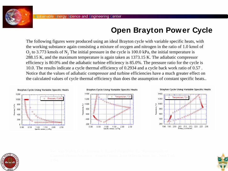
Open Brayton Power CycleThe following figures were produced using an ideal Brayton cycle with variable specific heats, with the working substance again consisting a mixture of oxygen and nitrogen in the ratio of 1.0 kmol of O2 to 3.773 kmols of N2 The initial pressure in the cycle is 100.0 kPa, the initial temperature is 288.15 K, and the maximum temperature is again taken as 1373.15 K. The adiabatic compressor efficiency is 80.0% and the adiabatic turbine efficiency is 85.0%. The pressure ratio for the cycle is 10.0. The results indicate a cycle thermal efficiency of 0.2934 and a cycle back work ratio of 0.57 . Notice that the values of adiabatic compressor and turbine efficiencies have a much greater effect on the calculated values of cycle thermal efficiency than does the assumption of constant specific heats..
Ref: Van Wylen, G. J., Sonntag, R. E., and Borgnakke, C., "Fundamentals of Classical Thermodynamics," Fourth Edition, John Wiley & Sons, Inc., New York, 1994.
Sustainable Energy Science and Engineering Center
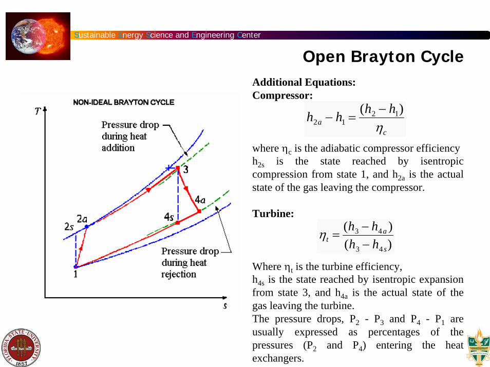
Open Brayton CycleAdditional Equations:Compressor:
where ηc is the adiabatic compressor efficiency h2s is the state reached by isentropic compression from state 1, and h2a is the actual state of the gas leaving the compressor.
Turbine:
Where ηt is the turbine efficiency,h4s is the state reached by isentropic expansion from state 3, and h4a is the actual state of the gas leaving the turbine.The pressure drops, P2 - P3 and P4 - P1 are usually expressed as percentages of the pressures (P2 and P4) entering the heat exchangers.
h2a − h1 =(h2 − h1)
ηc
ηt =(h3 − h4a )(h3 − h4 s)
Sustainable Energy Science and Engineering Center
Gas Turbine
Sustainable Energy Science and Engineering Center
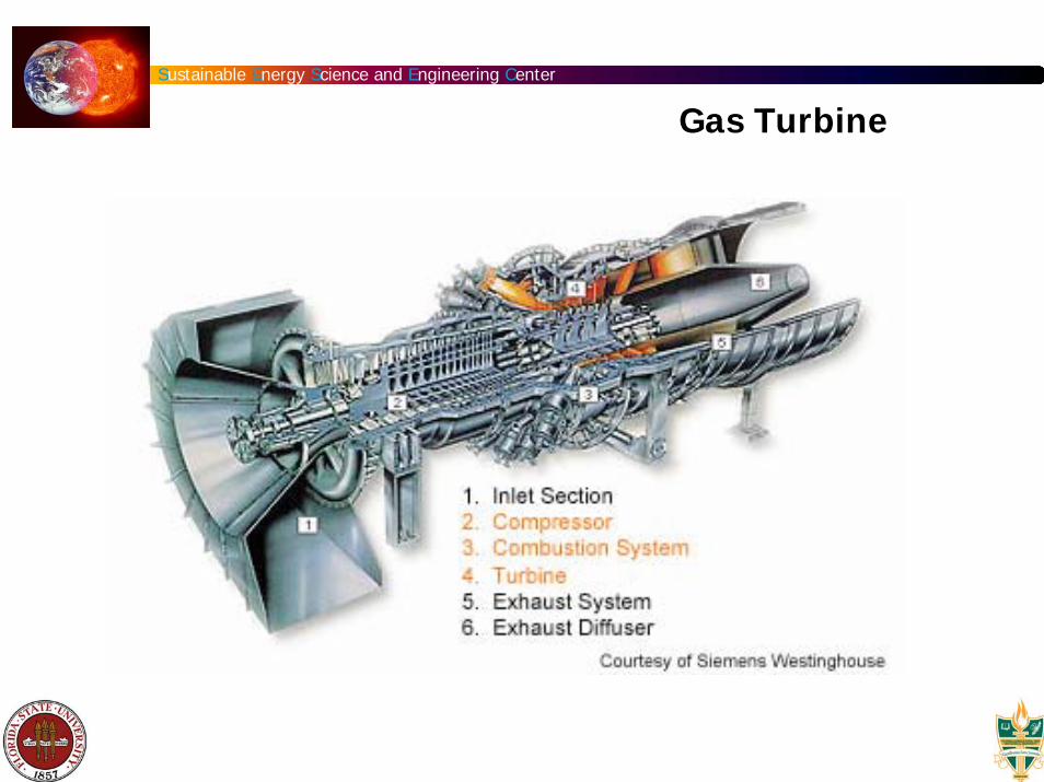
- The compressor which draws air into the engine, pressurizes it, and feeds it to the combustion chamber literally at speeds of hundreds of miles per hour.
- The combustion system, typically made up of a ring of fuel injectors that inject a steady stream of fuel (e.g., natural gas) into the combustion chamber where it mixes with the air. The mixture is burned at temperatures of more than 2000 degrees. The combustion produces a high temperature, high pressure gas stream that enters and expands through the turbine section.
- The turbine is an intricate array of alternate stationary and rotating aerofoil-section blades. As hot combustion gas expands through the turbine, it spins the rotating blades. The rotating blades perform a dual function: they drive the compressor to draw more pressurized air into the combustion section, and they spin a generator to produce electricity.
Gas Turbine
Sustainable Energy Science and Engineering Center
- Land based gas turbines are of two types: (1) heavy frame engines and (2) aeroderivative engines. Heavy frame engines are characterized by lower compression ratios (typically below 15) and tend to be physically large. Aeroderivative engines are derived from jet engines, as the name implies, and operate at very high compression ratios (typically in excess of 30). Aeroderivative engines tend to be very compact.
- One key to a turbine's fuel-to-energy efficiency is the temperature at which it operates. Higher temperatures generally mean higher efficiencies which, in turn, can lead to more economical operation. Gas flowing through a typical power plant turbine can be as hot as 2300 degrees F, but some of the critical metals in the turbine can withstand temperatures only as hot as 1500 to 1700 degrees F. Therefore air from the compressor is used for cooling key turbine components; however, the requirement for cooling the turbine limits the ultimate thermal efficiency.
Gas Turbine
Sustainable Energy Science and Engineering Center
- To boost efficiency is to install a recuperator or waste heat boiler onto the turbine's exhaust. A recuperator captures waste heat in the turbine exhaust system to preheat the compressor discharge air before it enters the combustion chamber. A waste heat boiler generates steam by capturing heat from the turbine exhaust. These boilers are also known as heat recovery steam generators (HRSG). High-pressure steam from these boilers can be used to generate additional electric power with steam turbines, a configuration called a combined cycle.
- A simple cycle gas turbine can achieve energy conversion efficiencies ranging between 20 and 35 percent. With the higher temperatures achieved in the turbine (2600oF), future gas turbine combined cycle plants are likely to achieve efficiencies of 60 percent or more. When waste heat is captured from these systems for heating or industrial purposes, the overall energy cycle efficiency could approach 80 percent.
Gas Turbine
Sustainable Energy Science and Engineering Center
Closed Brayton Power Cycle
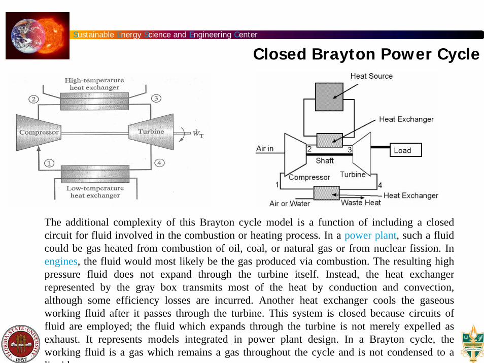
The additional complexity of this Brayton cycle model is a function of including a closed circuit for fluid involved in the combustion or heating process. In a power plant, such a fluid could be gas heated from combustion of oil, coal, or natural gas or from nuclear fission. In engines, the fluid would most likely be the gas produced via combustion. The resulting high pressure fluid does not expand through the turbine itself. Instead, the heat exchanger represented by the gray box transmits most of the heat by conduction and convection, although some efficiency losses are incurred. Another heat exchanger cools the gaseous working fluid after it passes through the turbine. This system is closed because circuits of fluid are employed; the fluid which expands through the turbine is not merely expelled as exhaust. It represents models integrated in power plant design. In a Brayton cycle, the working fluid is a gas which remains a gas throughout the cycle and is not condensed to a liquid
Sustainable Energy Science and Engineering Center
Brayton Cycle - Regeneration
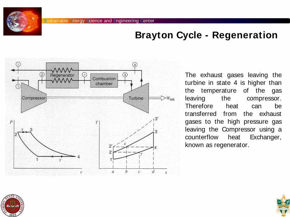
The exhaust gases leaving the turbine in state 4 is higher than the temperature of the gas leaving the compressor. Therefore heat can be transferred from the exhaust gases to the high pressure gas leaving the Compressor using a counterflow heat Exchanger, known as regenerator.
Sustainable Energy Science and Engineering Center
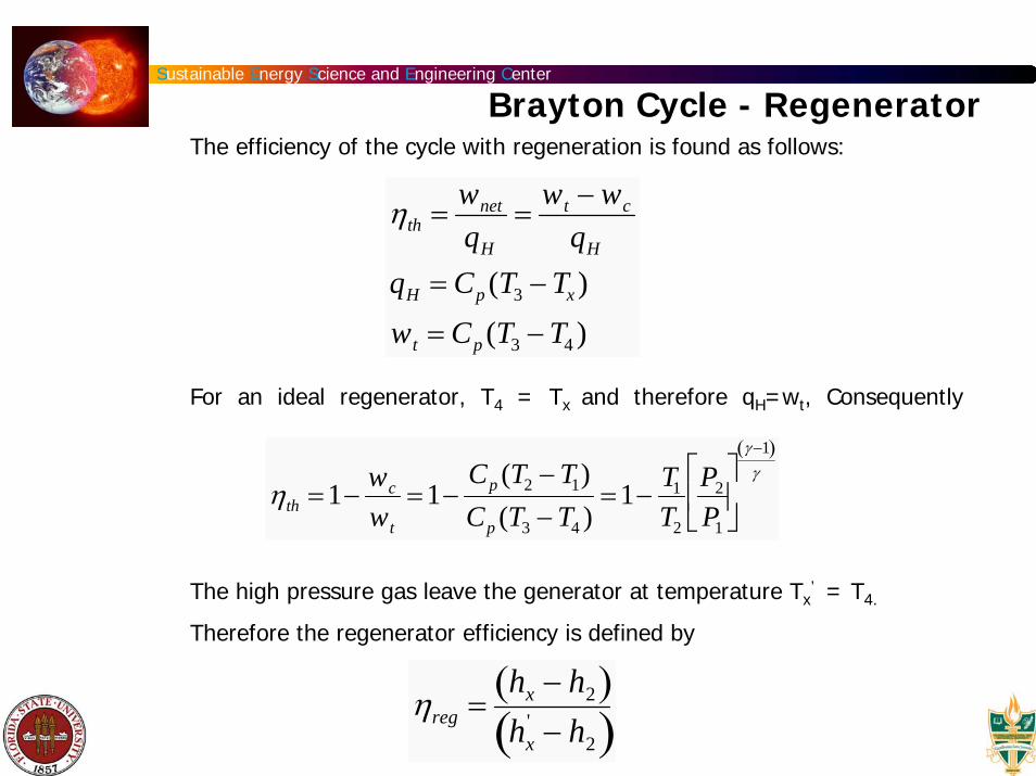
Brayton Cycle - RegeneratorThe efficiency of the cycle with regeneration is found as follows:
For an ideal regenerator, T4 = Tx and therefore qH=wt, Consequently
The high pressure gas leave the generator at temperature Tx’ = T4.
Therefore the regenerator efficiency is defined by
ηth =wnet
qH
=wt − wc
qH
qH = Cp (T3 − Tx )wt = Cp (T3 − T4 )
ηth =1−wc
wt
=1−Cp (T2 − T1)Cp (T3 − T4 )
=1−T1
T2
P2
P1
⎡
⎣ ⎢
⎤
⎦ ⎥
γ −1( )γ
ηreg =hx − h2( )hx
' − h2( )

Sustainable Energy Science and Engineering Center
Brayton Cycle with Regeneration and Intercooling
Sustainable Energy Science and Engineering Center
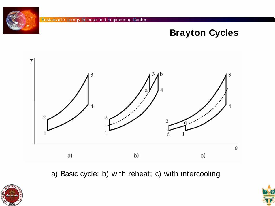
a) Basic cycle; b) with reheat; c) with intercooling
Brayton Cycles
Sustainable Energy Science and Engineering Center
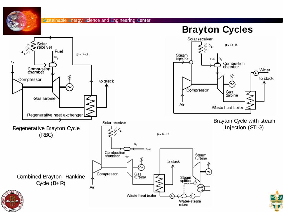
Regenerative Brayton Cycle (RBC)
Brayton Cycle with steam Injection (STIG)
Combined Brayton -Rankine Cycle (B+R)
Brayton Cycles
Sustainable Energy Science and Engineering Center
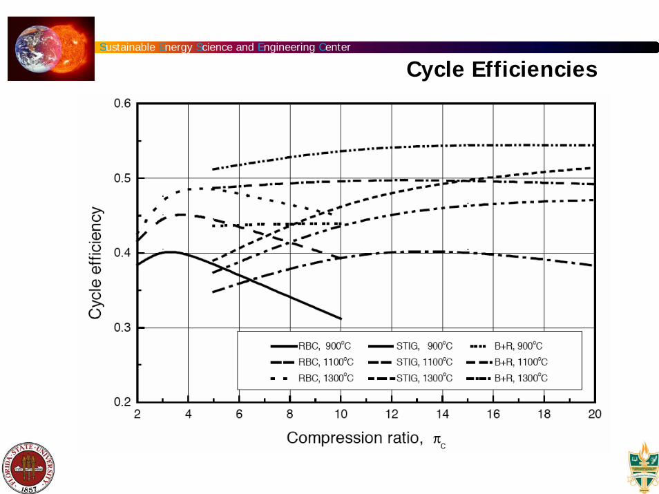
Cycle Efficiencies

Sustainable Energy Science and Engineering Center
Closed Solar Brayton Power Cycle
1999 Arthur D. Little Study for DOE
This concentric combustor surrounds the annular air passage of the working fluid (air) in its closed Brayton cycle. At full solar strength, without combustion augmentation, this two-stage turbo generator can produce an electrical output of up to 40 kW (equal to a 39% engine thermal efficiency).
The systems output can be augmented by the auxiliary gas combustor to produce up to 60 kW of electrical power. Utilization of the auxiliary combustor and closed Brayton cycle design make it possible for the turbo generator to operate efficiently over a full range of power conditions regardless of solar incidence.
Sustainable Energy Science and Engineering Center
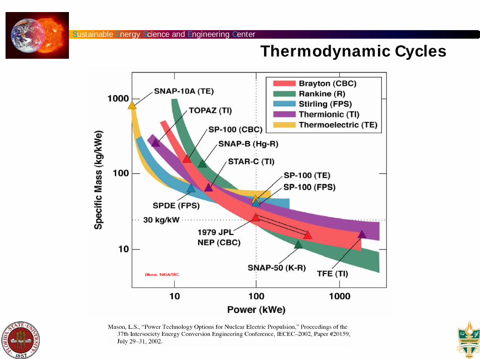
Thermodynamic Cycles
Sustainable Energy Science and Engineering Center
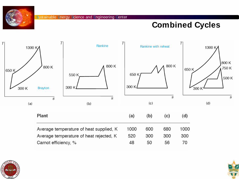
Combined Cycles
Brayton
Rankine Rankine with reheat
Sustainable Energy Science and Engineering Center
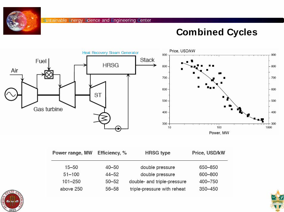
Heat Recovery Steam Generator
Combined Cycles
Sustainable Energy Science and Engineering Center
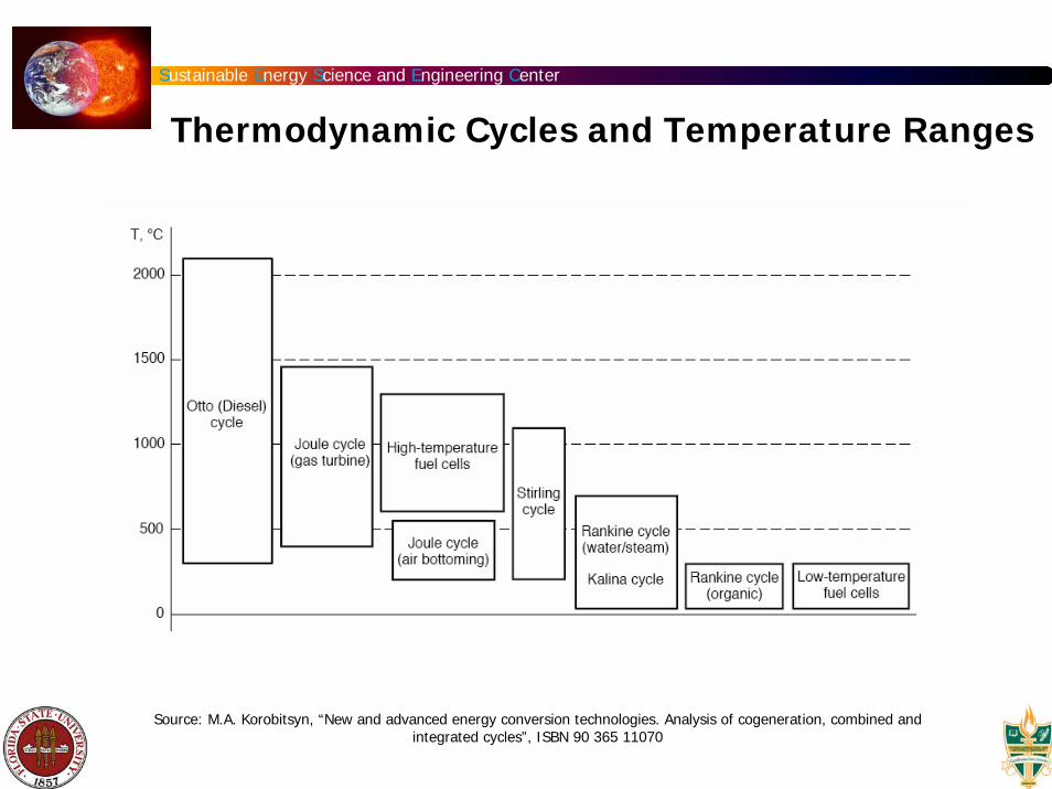
Thermodynamic Cycles and Temperature Ranges
Source: M.A. Korobitsyn, “New and advanced energy conversion technologies. Analysis of cogeneration, combined and integrated cycles”, ISBN 90 365 11070
Sustainable Energy Science and Engineering Center
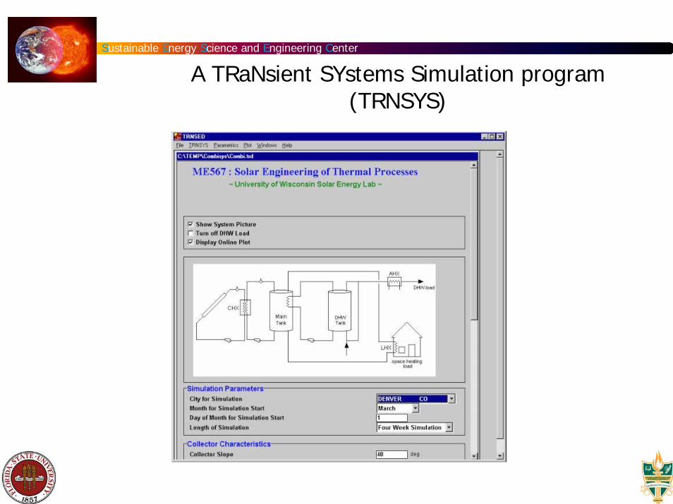
A TRaNsient SYstems Simulation program (TRNSYS)