THERMODYNAMIC AND STRUCTURAL DESIGN AND ANALYSIS … · thermodynamic and structural design and...
245
THERMODYNAMIC AND STRUCTURAL DESIGN AND ANALYSIS OF A NOVEL TURBO ROTARY ENGINE A THESIS SUBMITTED TO THE GRADUATE SCHOOL OF NATURAL AND APPLIED SCIENCES OF MIDDLE EAST TECHNICAL UNIVERSITY BY TAYLAN ERCAN IN PARTIAL FULFILLMENT OF THE REQUIREMENTS FOR THE DEGREE OF MASTER OF SCIENCE IN AEROSPACE ENGINEERING SEPTEMBER 2005
Transcript of THERMODYNAMIC AND STRUCTURAL DESIGN AND ANALYSIS … · thermodynamic and structural design and...
THERMODYNAMIC AND STRUCTURAL DESIGN AND ANALYSIS OF A
NOVEL TURBO ROTARY ENGINE
A THESIS SUBMITTED TO THE GRADUATE SCHOOL OF NATURAL AND APPLIED SCIENCES
OF MIDDLE EAST TECHNICAL UNIVERSITY
BY
TAYLAN ERCAN
IN PARTIAL FULFILLMENT OF THE REQUIREMENTS FOR
THE DEGREE OF MASTER OF SCIENCE IN
AEROSPACE ENGINEERING
SEPTEMBER 2005
Approval of the Graduate School of Natural and Applied Sciences
Prof. Dr. Canan ÖZGEN
I certify that this thesis satisfies all the requirements as a thesis for the degree of Master of Science.
Prof. Dr. Nafiz ALEMDAROĞLU Head of Department This is to certify that we have read this thesis and that in our opinion it is fully adequate, in scope and quality, as a thesis for the degree of Master of Science. Assoc. Prof. Dr. Altan KAYRAN Prof. Dr. İ. Sinan AKMANDOR Co-Supervisor Supervisor Examining Committee Members Prof. Dr. Cevdet Çelenligil (METU, AEE)
Prof. Dr. İ. Sinan Akmandor (METU, AEE)
Prof. Dr. Mehmet Şerif Kavsaoğlu (ITU, AEE)
Assoc. Prof. Dr. Ozan Tekinalp (METU, AEE)
Assoc. Prof. Dr. Altan Kayran (METU, AEE)

iii
I hereby declare that all information in this document has been obtained and presented in accordance with academic rules and ethical conduct. I also declare that, as required by these rules and conduct, I have fully cited and referenced all material and results that are not original to this work. Name, Last name: Taylan ERCAN
Signature :

iv
ABSTRACT
THERMODYNAMIC AND STRUCTURAL DESIGN AND ANALYSIS OF A NOVEL TURBO ROTARY ENGINE
Ercan, Taylan
M.Sc., Department of Aerospace Engineering
Supervisor : Prof. Dr. İ.Sinan Akmandor
Co-Supervisor: Assoc. Prof. Dr. Altan Kayran
September 2005, 227 pages
A novel turbo rotary engine, operating according to a novel thermodynamic
cycle, having an efficient compression phase, a limited temperature combustion
phase followed by a long power extraction phase is designed. Thermodynamic and
structural design and analysis of this novel engine is carried out and two prototypes
are manufactured according to these analysis. High performance figures such as
torque, power and low specific fuel consumption are calculated. Also the component
tests of the manufactured prototypes are completed and their results are
demonstrated.
Keywords: Internal combustion engine, Rotary engine, Novel thermodynamic cycle,
Structural design and analysis of an engine, Engine test.

v
ÖZ
YENİ BİR TURBO DÖNGÜSEL MOTORUN TERMODİNAMİK VE YAPISAL TASARIMI VE ANALİZİ.
Ercan, Taylan
Y. Lisans, Havacılık ve Uzay Mühendisliği Bölümü
Tez Yöneticisi : Prof. Dr. İ. Sinan Akmandor
Ortak Tez Yöneticisi: Doç. Dr. Altan Kayran
Eylül 2005, 227 sayfa
Verimli bir sıkıştırma evresi, limitli sıcaklıktaki yanma evresi ve bunu takip
eden uzun bir güç alma evresinden oluşan yeni bir termodinamik çevrim ile çalışan
yeni bir turbo döngüsel motor tasarlanmıştır. Motorun termodinamik ve yapısal
tasarımı ve analizleri yapılmış ve bu analizler doğrultusunda iki tane prototip imal
edilmiştir. Tork, güç ve düşük yakıt tüketimi gibi yüksek performans değerleri
hesaplanmıştır. Ayrıca imal edilen prototiplerin komponent testleri tamamlanmış ve
sonuçlar sunulmuştur.
Anahtar Kelimeler: İçten yanmalı motor, Döngüsel motor, Yeni termodinamik
çevrim, Motor yapısal tasarımı ve analizi, Motor test.

vi
To My Father

vii
ACKNOWLEDGMENTS
I would like to express my gratitude to my thesis supervisor Prof. Dr. İ. Sinan
Akmandor and my co-supervisor Assoc. Prof. Dr. Altan Kayran for their guidance,
advice, criticism, encouragements and insight throughout the research.
I would also like to thank Mr. Ahmet Tütüncü, Mr. Nizamettin Minaz and
Mr. Bülent Erbay from the manufacturing department of TAI and the workshop staff,
for their great support in making this design real.
The technical assistance of Mr. Gökhan Aran and Mr. Ahmet Yürür are
gratefully acknowledged.
Special thanks to my wife, Nil Ercan, and my family for their endless love
and great support through out my studies and my career.
This study was supported by Tusas Engine Industry (TEI), and Tusas Aircraft
Industry (TAI).

viii
TABLE OF CONTENTS PLAGIARISM……………………………………………………………….... iii ABSTRACT…………………………………………………………………..... iv ÖZ………………………………………………………………………….….. v DEDICATION…………………………………………………………….…... vi ACKNOWLEDGMENTS…………………………………………………..… vii TABLE OF CONTENTS…………………………………………………..…... viii LIST OF TABLES……………………………………………………….…..... x LIST OF FIGURES……………………………………………………….…... xi NOMENCLATURE……………………………………………………….…... xv LIST OF ACRONYMS………………………………………………….……. xviii 1 INTRODUCTION………………………………………………………..... 1 1.1 History of Internal Combustion Engines………………………………. 2 1.2 Main Types of Internal Combustion Engines………………………… 8 1.3 Thermodynamic Cycles of Engines………………………………..….. 15 1.4 Rotary Engine Development…………………………………………... 19 1.5 Reciprocating Versus Rotary Engines……………………………….… 20 1.6 Characteristics of the Novel Rotary Engine…………………………… 22 1.6.1 Improved Thermodynamic Cycle……………………………… 22 1.6.2 Limited Peak, Extended Expansion Thermodynamic Cycle..…. 22 1.6.3 Separate Compression and Expansion Chambers………………. 23 1.6.4 Improved Sealing and Avoiding Wear…………………………. 24 1.7 Outline of the Thesis…………………………………………………... 25 2 THERMODYNAMIC DESIGN OF THE NOVEL ROTARY ENGINE…. 26 2.1 Novel Thermodynamic Cycle……………………………………….…. 26 2.1.1 P – V, T – S Diagrams…………………………………………. 27 2.1.2 Efficiency of the Cycle…………………………………………. 30 2.2 Dimensioning the Engine……………………………………………… 33 2.2.1 Thermodynamic Design Code………………………………… 33 2.2.2 Requirements of the Engine…………………………………… 44 3 STRUCTURAL AND MECHANICAL DESIGN OF THE NOVEL TURBO ROTARY ENGINE…………………………………….................
50
3.1 Compressor Design……………………………………………………. 50 3.1.1 Compressor Parts……………………………………………… 58 3.1.2 Structural Analysis and Material Selection…………………….. 64 3.2 Turbine Design………………………………………………………… 94 3.2.1 Turbine Parts………………………………………………….… 102 3.2.2 Structural Analysis and Material Selection…………………….. 108
ix
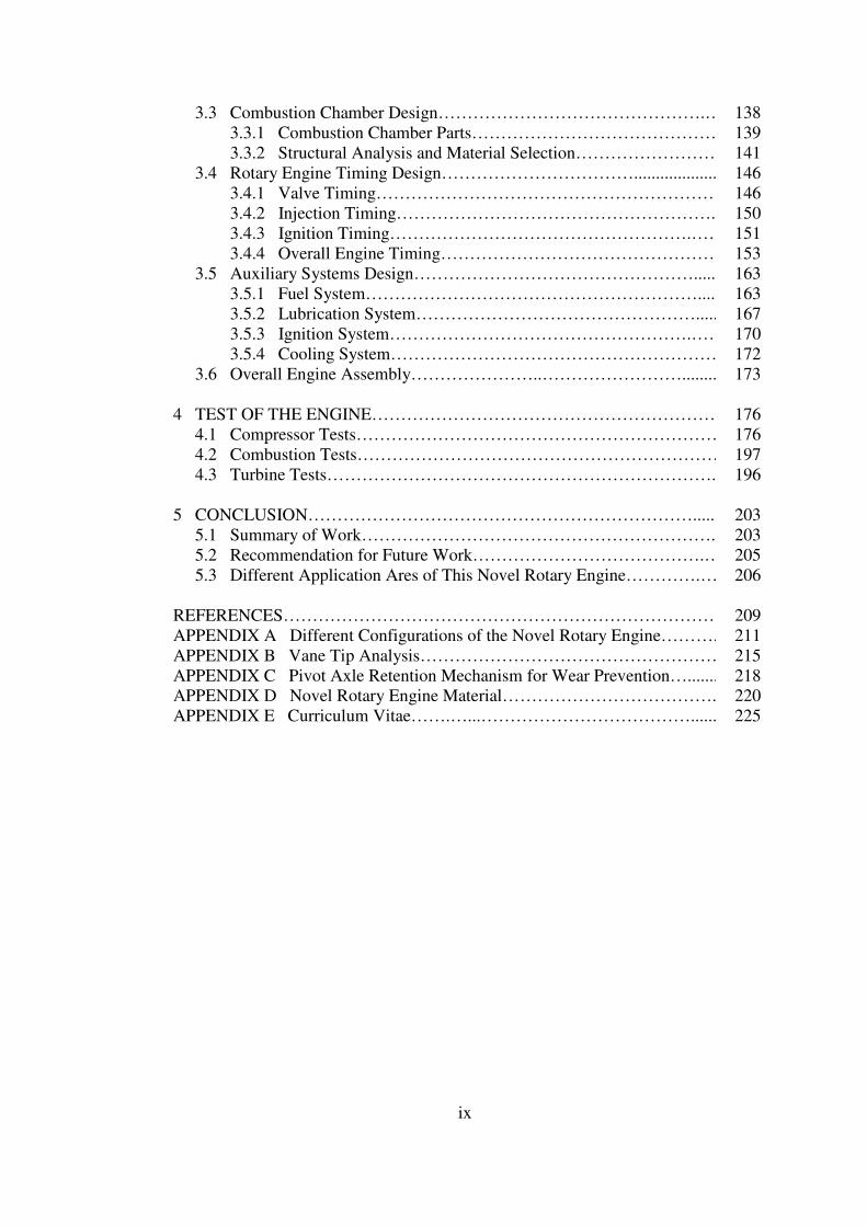
3.3 Combustion Chamber Design……………………………………….…. 138 3.3.1 Combustion Chamber Parts…………………………………… 139 3.3.2 Structural Analysis and Material Selection…………………….. 141 3.4 Rotary Engine Timing Design……………………………..................... 146 3.4.1 Valve Timing…………………………………………………… 146 3.4.2 Injection Timing……………………………………………….... 150 3.4.3 Ignition Timing…………………………………………….…… 151 3.4.4 Overall Engine Timing…………………………………………. 153 3.5 Auxiliary Systems Design…………………………………………....... 163 3.5.1 Fuel System…………………………………………………...... 163 3.5.2 Lubrication System…………………………………………...... 167 3.5.3 Ignition System…………………………………………….…… 170 3.5.4 Cooling System………………………………………………… 172 3.6 Overall Engine Assembly…………………..…………………….......... 173 4 TEST OF THE ENGINE……………………………………………………. 176 4.1 Compressor Tests……………………………………………………… 176 4.2 Combustion Tests……………………………………………………… 197 4.3 Turbine Tests…………………………………………………………... 196 5 CONCLUSION…………………………………………………………..... 203 5.1 Summary of Work……………………………………………………... 203 5.2 Recommendation for Future Work………………………………….…. 205 5.3 Different Application Ares of This Novel Rotary Engine………….….. 206 REFERENCES………………………………………………………………… 209 APPENDIX A Different Configurations of the Novel Rotary Engine……….. 211 APPENDIX B Vane Tip Analysis……………………………………………. 215 APPENDIX C Pivot Axle Retention Mechanism for Wear Prevention…....... 218 APPENDIX D Novel Rotary Engine Material……………………………….. 220 APPENDIX E Curriculum Vitae…….…...………………………………...... 225
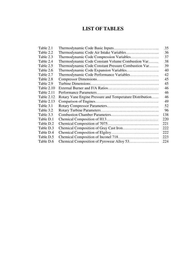
LIST OF TABLES Table 2.1 Thermodynamic Code Basic Inputs…………………………….… 35 Table 2.2 Thermodynamic Code Air Intake Variables…………………….... 36 Table 2.3 Thermodynamic Code Compression Variables………………….. 37 Table 2.4 Thermodynamic Code Constant Volume Combustion Var…….… 38 Table 2.5 Thermodynamic Code Constant Pressure Combustion Var……… 39 Table 2.6 Thermodynamic Code Expansion Variables……………………... 40 Table 2.7 Thermodynamic Code Performance Variables…………………... 42 Table 2.8 Compressor Dimensions…………………………………………. 45 Table 2.9 Turbine Dimensions……………………………………………… 45 Table 2.10 External Burner and F/A Ratios…………………………………. 46 Table 2.11 Performance Parameters………………………………………… 46 Table 2.12 Rotary Vane Engine Pressure and Temperature Distribution……. 46 Table 2.13 Comparison of Engines…………………………………………... 49 Table 3.1 Rotary Compressor Parameters…………………………………... 52 Table 3.2 Rotary Turbine Parameters……………………………………….. 96 Table 3.3 Combustion Chamber Parameters………………………………... 138 Table D.1 Chemical Composition of H13…………………………………… 220 Table D.2 Chemical Composition of 7075…………………………………. 221 Table D.3 Chemical Composition of Gray Cast Iron………………………... 222 Table D.4 Chemical Composition of Elgiloy………………………………... 222 Table D.5 Chemical Composition of Inconel 718………………………….. 223 Table D.6 Chemical Composition of Pyrowear Alloy 53…………………… 224

xi
LIST OF FIGURES Figure 1-1 Reciprocating Engine………………………………………… 9 Figure 1-2 Wankel Engine……………………………………………….. 10 Figure 1-3 Two Stroke Cycle Engine……………………………………. 11 Figure 1-4 Four Stroke Cycle Engine……………………………………. 12 Figure 1-5 P – V Diagram of Carnot Cycle……………………………… 15 Figure 1-6 P – V Diagram of Otto Cycle………………………………… 16 Figure 1-7 P – V Diagram of Diesel Cycle………………………………. 17 Figure 1-8 P – V Diagram of Brayton Cycle…………………………….. 18 Figure 2-1 Thermodynamic Cycle (P – V) for Rotary Vane Engine…….. 27 Figure 2-2 Thermodynamic Cycle (T – S) for Rotary Vane Engine……. 28 Figure 2-3 P-θ Chart for the Novel Thermodynamic Cycle…………….. 29 Figure 2-4 Thermodynamic Cycle of the Duel (Otto-Diesel) Cycle……. 29 Figure 2-5 The Flowchart of The Thermodynamic Code……………….. 34 Figure 2-6 Compressor Air Intake Phase……………………………….… 35 Figure 2-7 Compression Phase………………………………………….. 37 Figure 2-8 Constant Volume Combustion Phase……………………….… 38 Figure 2-9 Constant Pressure Combustion Phase……………………….... 39 Figure 2-10 Turbine Expansion Phase…………………………………….. 40 Figure 2-11 P – V Diagram of Novel Thermodynamic Cycle……………. 43 Figure 2-12 T - S Diagram of Novel Thermodynamic Cycle…………….. 43 Figure 2-13 Turna, TAI’s Unmanned Air Vehicle………………………... 44 Figure 2-14 Rotary Vane Engine Shaft Power vs. RPM…………….…….. 47 Figure 2-15 Rotary Vane Engine Specific Fuel Consumption vs. RPM….. 48 Figure 2-16 Rotary Vane Engine Net Torque vs. RPM…………………… 48 Figure 3-1 Rotary Compressor Diagram…………………………………. 51 Figure 3-2 Rotary Compressor Kinematics…………………………….… 52 Figure 3-3 Rotary Compressor Inlet Volume………………………….…. 54 Figure 3-4 2-D Drawing of Rotary Compressor……………………….…. 56 Figure 3-5 3-D Wire-Frame Drawing of Rotary Compressor……………. 56 Figure 3-6 3-D CAD Model of the Rotary Compressor………………… 57 Figure 3-7 Photograph of the Manufactured Rotary Compressor……….. 57 Figure 3-8 Compressor Housing Model………………………………….. 58 Figure 3-9 Compressor Upper Tap Model……………………………….. 59 Figure 3-10 Compressor Lower Tap………………………………………. 60 Figure 3-11 Compressor Rotor……………………………………………. 61 Figure 3-12 Compressor Vane…………………………………………….. 62 Figure 3-13 Compressor Discharge Valve………………………………… 63 Figure 3-14 Pressure Distribution in the Rotary Compressor……………... 65 Figure 3-15 Temperature Distribution In the Rotary Compressor………… 65 Figure 3-16 Structural Analysis Model of the Compressor Housing……… 67 Figure 3-17 Temperature Distribution on Compressor Housing…………. 67 Figure 3-18 Stress Distribution on the Compressor Housing…………….... 68 Figure 3-19 Deformation on the Compressor Housing……………………. 68
xii
Figure 3-20 Structural Analysis Model of the Compressor Upper Tap……. 70 Figure 3-21 Temperature Distribution on Compressor Upper Tap………... 70 Figure 3-22 Stress Distribution on the Compressor Upper Tap…………… 71 Figure 3-23 Deformation on the Compressor Upper Tap………………… 71 Figure 3-24 Structural Analysis Model of the Compressor Lower Tap…... 73 Figure 3-25 Temperature Distribution on Compressor Lower Tap………. 73 Figure 3-26 Stress Distribution on the Compressor Lower Tap………….... 74 Figure 3-27 Deformation on the Compressor Lower Tap…………………. 74 Figure 3-28 Structural Analysis Model of the Compressor Vane…………. 76 Figure 3-29 Stress Distribution on Compressor Vane…………………….. 76 Figure 3-30 Deformation on the Compressor Vane…………………….…. 77 Figure 3-31 Structural Analysis Model of the Compressor Rotor………… 79 Figure 3-32 Temperature Distribution on Compressor Rotor……………... 79 Figure 3-33 Stress Distribution on the Compressor Rotor………………… 80 Figure 3-34 Deformation on the Compressor Rotor………………………. 80 Figure 3-35 Structural Analysis Model of the Compressor Discharge V… 82 Figure 3-36 Temperature Distribution on Compressor Discharge Valve… 82 Figure 3-37 Stress Distribution on the Compressor Discharge Valve...….. 83 Figure 3-38 Deformation on the Compressor Discharge Valve………...... 83 Figure 3-39 Structural Analysis Model of Compressor Vane Apex S……. 85 Figure 3-40 Stress Distribution on Compressor Vane Apex Seal………… 85 Figure 3-41 Deformation of Compressor Vane Apex Seal………………... 86 Figure 3-42 Structural Analysis Model of Compressor Rotor Top Seal….. 88 Figure 3-43 Stress Distribution on Compressor Rotor Top Seal………….. 88 Figure 3-44 Deformation of Compressor Rotor Top Seal…………….…… 89 Figure 3-45 Rotary Turbine Diagram……………………………………... 95 Figure 3-46 Rotary Turbine Kinematics…………………………………... 96 Figure 3-47 Turbine Expansion Volume…………………………………. 98 Figure 3-48 2-D Drawing of Rotary Turbine……………………………… 100 Figure 3-49 3-D Wire-Frame Drawing of Rotary Compressor……………. 100 Figure 3-50 3-D CAD Model of the Rotary Turbine……………………… 101 Figure 3-51 Photograph of the Manufactured Turbine……………………. 101 Figure 3-52 Turbine Housing Model……………………………………… 102 Figure 3-53 Turbine Upper Tap Model……………………………………. 103 Figure 3-54 Turbine Lower Tap…………………………………………… 104 Figure 3-55 Turbine Rotor………………………………………………… 105 Figure 3-56 Turbine Vane…………………………………………………. 106 Figure 3-57 Turbine Inlet Valve…………………………………………... 107 Figure 3-58 Pressure Distribution in the Rotary Turbine……………….…. 109 Figure 3-59 Temperature Distribution in the Turbine…………………….. 109 Figure 3-60 Structural Analysis Model of the Turbine Housing………….. 111 Figure 3-61 Temperature Distribution on Turbine Housing………………. 111 Figure 3-62 Stress Distribution on the Turbine Housing………………….. 112 Figure 3-63 Deformation on the Turbine Housing………………………... 112 Figure 3-64 Structural Analysis Model of the Turbine Upper Tap………... 114 Figure 3-65 Temperature Distribution on Turbine Upper Tap…………… 114 Figure 3-66 Stress Distribution on the Turbine Upper Tap……………….. 115
xiii
Figure 3-67 Deformation on the Turbine Upper Tap……………………… 115 Figure 3-68 Structural Analysis Model of the Turbine Lower Tap……….. 117 Figure 3-69 Temperature Distribution on Turbine Lower Tap…………… 117 Figure 3-70 Stress Distribution on the Turbine Lower Tap……………….. 118 Figure 3-71 Deformation on the Turbine Lower Tap……………………... 118 Figure 3-72 Structural Analysis Model of the Turbine Vane……………... 120 Figure 3-73 Stress Distribution on Turbine Vane…………………………. 120 Figure 3-74 Deformation on the Turbine Vane……………………….…… 121 Figure 3-75 Structural Analysis Model of the Turbine Rotor……………... 123 Figure 3-76 Temperature Distribution on Turbine Rotor……………….…. 123 Figure 3-77 Stress Distribution on the Turbine Rotor…………………...… 124 Figure 3-78 Deformation on the Turbine Rotor…………………………… 124 Figure 3-79 Structural Analysis Model of the Turbine Inlet Valve……….. 126 Figure 3-80 Temperature Distribution on Turbine Inlet Valve……………. 126 Figure 3-81 Stress Distribution on the Turbine Inlet Valve……………….. 127 Figure 3-82 Deformation on the Turbine Inlet Valve……………………... 127 Figure 3-83 Structural Analysis Model of the Turbine Vane Apex Seal…. 129 Figure 3-84 Stress Distribution on Turbine Vane Apex Seal……………... 129 Figure 3-85 Deformation of Turbine Vane Apex Seal……………………. 130 Figure 3-86 Structural Analysis Model of the Turbine Rotor Top Seal…... 132 Figure 3-87 Stress Distribution on Turbine Rotor Top Seal………………. 132 Figure 3-88 Deformation of Turbine Rotor Top Seal……………………... 133 Figure 3-89 3-D Wire-Frame Drawing of Combustion Chamber…………. 139 Figure 3-90 3-D CAD Model of the Combustion Chamber………….……. 140 Figure 3-91 Photograph of the Combustion Chamber……………….…..... 140 Figure 3-92 Structural Analysis Model of the Combustion Chamber…….. 143 Figure 3-93 Temperature Distribution on the Combustion Chamber……... 143 Figure 3-94 Stress Distribution on the Combustion Chamber…………….. 144 Figure 3-95 Compressor Vane Angle……………………………………... 146 Figure 3-96 Turbine Vane Angle………………………………………….. 146 Figure 3-97 External Burner Angle……………………………………….. 147 Figure 3-98 Compressor Valve Angle…………………………………….. 147 Figure 3-99 Turbine Valve Angle…………………………………………. 148 Figure 3-100 Valve Angles…………………………………………………. 148 Figure 3-101 Valve Timing…………………………………………………. 149 Figure 3-102 Timing Disk………………………………………………….. 150 Figure 3-103 Hall Effect Switch System………………………………….… 151 Figure 3-104 Timing Disk………………………………………………….. 152 Figure 3-105 Air Intake of the Novel Rotary Engine…………………........ 153 Figure 3-106 Max Air Taken of the Novel Rotary Engine………………… 154 Figure 3-107 Air Discharge of the Novel Rotary Engine…………………... 155 Figure 3-108 Fuel Injection to the First Combustion Chamber…………….. 156 Figure 3-109 Ignition in the First Combustion Chamber…………………... 157 Figure 3-110 First Combustion Gas Discharge to the Rotary Turbine……... 158 Figure 3-111 Expansion in the Rotary Turbine………………………….….. 159 Figure 3-112 Ignition in the Second Combustion Chamber………………... 160 Figure 3-113 Second Combustion Gas Discharge to the Rotary Turbine...... 161

xiv
Figure 3-114 Exhaust of the First Combustion Gases………………….…… 162 Figure 3-115 Carburetion System Schematic………………………….……. 136 Figure 3-116 Carburetor…………………………………………………….. 164 Figure 3-117 Direct Injection System Schematic…………………………... 165 Figure 3-118 Fuel Injector………………………………………………….. 165 Figure 3-119 Fuel Pump……………………………………………….……. 166 Figure 3-120 Oil Pump……………………………………………………... 168 Figure 3-121 Oil Pump Drawing…………………………………………… 168 Figure 3-122 Lubrication System Schematic……………………………….. 169 Figure 3-123 Capacitive Discharge Ignition System……………………….. 170 Figure 3-124 Ignition System with Combustion Chamber…………………. 171 Figure 3-125 Ground Test Cooling…………………………………………. 172 Figure 3-126 Overall Engine Assembly Scheme…………………………… 173 Figure 3-127 3-D Wire-Frame Drawing of Overall Engine Assembly…….. 174 Figure 3-128 3-D CAD Model of Overall Engine Assembly………………. 174 Figure 3-129 3-D CAD Model of Test Stand………………………………. 175 Figure 3-130 Photograph of Test Stand…………………………………….. 175 Figure 4-1 Compressor Mass Flow Rate versus Rpm Chart……………... 192 Figure 4-2 Compressor Volumetric Eff. versus Rpm Chart……………... 192 Figure 4-3 Compressor Pressure versus Rpm Chart……………………... 193 Figure 4-4 Compressor Efficiency versus Rpm Chart…………………… 193 Figure 4-5 Turbine Rpm versus Mass Flow Rate Chart…………………. 200 Figure 4-6 Turbine Rpm versus Pressure Chart…………………………. 200 Figure 4-7 Turbine Mass Flow Rate versus Pressure Chart……….......... 201 Figure 5-1 Schematic Diagram of Turbo Rotary Compound Engine……. 207 Figure 5-2 3-D Model of Turbo Rotary Compound Engine…………….... 207 Figure 5-3 Micro Rotary Engine…………………………………………. 208 Figure A-1 3-D CAD Model of 1st Side by Side Configuration………….. 212 Figure A-2 2-D CAD Model of 1st Side by Side Configuration………….. 212 Figure A-3 3-D CAD Model of 2nd Side by Side Configuration…………. 214 Figure A-4 2-D CAD Model of 2nd Side by Side Configuration…………. 214 Figure B-1 Analytical Vane Tip Geometry………………………………. 215 Figure B-2 Vane Tip Contact Analysis…………………………………... 217 Figure C-1 Sliding Vane and Centrally Placed Vane Retention Mech….. 219
xv
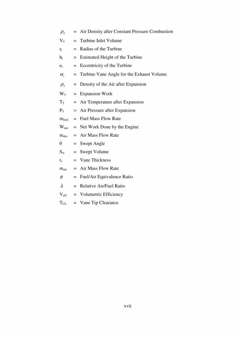
NOMENCLATURE
ηth = Thermal Efficiency
TL = Lowest Temperature
TH = Highest Temperature
P = Pressure
V = Volume
r = Compression Ratio
k = Polytrophic Coefficient
Cp = Specific Heat Coefficient (Constant P)
Cv = Specific Heat Coefficient (Constant V)
rc = Cut Off Ratio
rp = Pressure Ratio
s = Entropy
θec = External Combustion Angle
θic = Internal Combustion Angle
θcp = Constant Pressure Combustion Angle
θce = Compressor Exit Angle
θci = Compressor Inlet Angle
θs = Stroke Angle
θti = Turbine inlet Angle
θe = Exhaust Angle
θeb = External Burning Angle
θib = Internal Burning Angle
θvc = Compressor Vane Open Angle
θvti = Turbine Vane Angle
θphase = Phase Angle Between Turbine and Compressor
θvte = Turbine Displacement Angle
θpp = Process Period Angle
Qin = Energy Input
xvi
Qout = Energy Output
P1 = Atmospheric Air Pressure
T1 = Atmospheric Air Temperature
1ρ = Atmospheric Air Density
R = Universal Gas Coefficient
Far = Fuel/Air Ratio
hfu = Fuel Enthalpy
V1 = Compressor Inlet Volume
rc = Radius of the Compressor
ec = Eccentricity of the Compressor
c
α = Compressor Vane Front Angle for the Inlet Volume
c
δ = Compressor Vane Back Angle for the Inlet Volume
m = Mass of the Air
1ρ = Density of Air at Inlet
hc = Height of the Compressor
dc = Diameter of Compressor
P2 = Air Pressure after Compression
T2 = Air Temperature after Compression
2ρ = Air Density after Compression
W2 = Compression Work
V2 = Combustion Chamber Volume
T3 = Air Temperature after Constant Volume Combustion
fcv = Constant Volume Combustion Fuel Ratio
P3 = Air Pressure after Constant Volume Combustion
V3 = Combustion Chamber Volume
3ρ = Air Density after Constant Volume Combustion
T4 = Air Temperature after Constant Pressure Combustion
P4 = Air Pressure after Constant Pressure Combustion
V4 = Combustion Chamber Volume
xvii
4ρ = Air Density after Constant Pressure Combustion
V5 = Turbine Inlet Volume
rt = Radius of the Turbine
ht = Estimated Height of the Turbine
et = Eccentricity of the Turbine
t
α = Turbine Vane Angle for the Exhaust Volume
5ρ = Density of the Air after Expansion
W5 = Expansion Work
T5 = Air Temperature after Expansion
P5 = Air Pressure after Expansion
mfuel = Fuel Mass Flow Rate
Wnet = Net Work Done by the Engine
mdot = Air Mass Flow Rate
θ = Swept Angle
Sw = Swept Volume
tv = Vane Thickness
mair = Air Mass Flow Rate
φ = Fuel/Air Equivalence Ratio
λ = Relative Air/Fuel Ratio
Veff = Volumetric Efficiency
TCL = Vane Tip Clearance
xviii
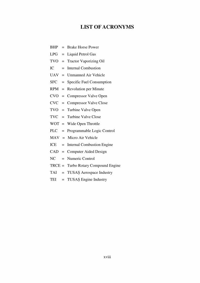
LIST OF ACRONYMS BHP = Brake Horse Power
LPG = Liquid Petrol Gas
TVO = Tractor Vaporizing Oil
IC = Internal Combustion
UAV = Unmanned Air Vehicle
SFC = Specific Fuel Consumption
RPM = Revolution per Minute
CVO = Compressor Valve Open
CVC = Compressor Valve Close
TVO = Turbine Valve Open
TVC = Turbine Valve Close
WOT = Wide Open Throttle
PLC = Programmable Logic Control
MAV = Micro Air Vehicle
ICE = Internal Combustion Engine
CAD = Computer Aided Design
NC = Numeric Control
TRCE = Turbo Rotary Compound Engine
TAI = TUSAŞ Aerospace Industry
TEI = TUSAŞ Engine Industry
1
CHAPTER 1
INTRODUCTION
Since the start of the industrial revolution, the reciprocating piston engine based
on the Otto and Diesel cycles and, the gas turbine engine based on the Brayton cycle,
have largely dominated the market [1]. Despite this fact, for many years, patents on
rotary combustion engines [2,3,4,5,6] have claimed that rotary engines possess many
advantages over reciprocating engines such as having high torque, fewer parts, lower
weight and fewer reciprocating imbalance. Although heat engines have received little
industrial attention, for over 5 decades, sliding vane rotary compressors have taken
an important place in general engineering applications, especially in the capacity
range of 10-1000 cc/sec and for delivery pressures in the range of 2-18 bars. Early
rotary compressor designs had low volumetric efficiencies, undesirable high delivery
air temperatures due to internal air leakage and considerable blade and cylinder wear
due to lack of adequate lubrication [1]. These disadvantages have all been addressed
in this thesis. In this thesis, an engine compressor with a volumetric efficiency of
85.6% is designed and the long expansion power stroke which lasts up to a wide
rotation angle (270°), is amply sufficient to overtake any net shaft power production
figure of a non-turbocharged piston engine of similar size and of higher compressor
volumetric efficiency. Further, the longer compression stroke rotation angle (330°)
enhances the fuel-air mixing as fuel is injected by a carburetor alongside the air
intake phase. The fuel evaporates in the compression phase and helps lower the
compression temperature which further decreases the required shaft power input to
the rotary compressor. A good fuel-air mixing permits leaner combustion to occur in
the external burner which is placed downstream of the compressor.
2
Contrary to expectations gained through the design of compression devices, a
high compressor air delivery temperature positively contributes to the temperature
rise requirement in the combustion chamber.
As less fuel input is needed to reach allowable turbine inlet temperature, the
specific fuel consumption is favorably decreased.
Air and oil cooled sliding vane engine have additional very desirable features
such as nearly steady air flow processing, small pressure fluctuations, low noise
levels and smooth running characteristics.
Another objective of this thesis is to increase the overall thermal efficiency above
levels reached by today’s heat engines. This is achieved by adopting a novel
thermodynamic cycle which allows a longer power extraction phase. The designed
rotary vane engine also achieves high compression ratios with less shaft power input
as air is processed through a smooth crescent shape constriction which progressively
squeezes out the fluid to the combustion chamber. As maximum peak temperature is
limited, the operational and maintenance costs are also minimized. All together, in
the presented thesis, an efficient, powerful, compact, simple and reliable heat engine
is designed, analyzed, manufactured and tested.
1.1 History of Internal Combustion Engines
The purpose of internal combustion engines is the production of mechanical
power from chemical energy contained in the fuel. In internal combustion engines, as
distinct from external combustion engines, this energy is released by burning or
oxidizing the fuel inside the engine. The fuel – air mixture before the combustion,
and the burned products after combustion are the actual working fluids. The work
transfers which provide the desired power output occur directly between these
working fluids and the mechanical components of the engine. The spark ignition
engines (sometimes called Otto engines or gasoline engines), compression – ignition
or diesel engines are the main internal combustion engines.
3
Because of their simplicity, ruggedness and high power/weight ratio, these two
types of engine have found wide application in transportation (land, sea and air) and
power generation. It is the fact that combustion takes place inside the work
producing part of these engines that makes their design and operating characteristics
fundamentally different from those of other types of engines.
Practical heat engines have served mankind for over two and a half centuries. For
the first 150 years, water rose to steam, was interposed between the combustion
gases produced by burning the fuel and the work producing piston in cylinder
expander. It was not until the 1860s that the internal combustion engine became a
practical reality [7,8]. The early engines developed for commercial use burned coal-
gas air mixtures at atmospheric pressure- there was no compression before
combustion. J.J.E. Lenoir (1822-1900) developed the first marketable engine of this
type. Gas and air were drawn into the cylinder during the first half of the piston
stroke. The charge was then ignited with a spark, the pressure increased, and the
burned gases then delivered power to the piston for the second half of the stroke. The
cycle was completed with an exhaust stroke. Some 5000 of these engines were built
between 1860 and 1865 in sizes up to six horsepower. Efficiency was at best about 5
percent.
A more successful development – an atmospheric engine introduced in 1867 by
Nicolaus A. Otto (1832-1891) and Eugen Langen (1833 – 1895) – used the pressure
rise resulting from combustion of the fuel – air charge early in the outward stroke to
accelerate a free piston and rack assembly so its momentum would generate a
vacuum in the cylinder. Atmospheric pressure then pushed the piston inward, with
the rack engaged through a roller clutch to the output shaft. Production engines, of
which about 5000 were built, obtained thermal efficiencies of up to 11 percent. A
slide valve controlled intake, ignition by a gas flame, and exhaust [8].
To overcome this engine’s shortcomings of low thermal efficiency and excessive
weight, Otto proposed an engine cycle with four piston strokes: an intake stroke, then
a compression stroke before ignition, an expansion or power stroke where work was
delivered to the crankshaft, and finally an exhaust stroke. His prototype four stroke
engine first ran in 1876.
4
A comparison between the Otto engine and the atmospheric type predecessor
indicates the reason for its success; the enormous reduction in engine weight and
volume. By 1890, almost 50,000 of these engines had been sold in Europe and the
United States [8].
In 1884, an unpublished French patent issued in 1862 to Alphonse Beau de
Rochas (1815 – 1893) was found which described the principles of the four stroke
cycle. This chance discovery cast doubt on the validity of Otto’s own patent for this
concept, and in Germany it was declared invalid. Beau de Rochas also outlined the
conditions under which maximum efficiency in an external combustion engine could
be achieved [9]. These were:
1. The largest possible cylinder volume with minimum boundary surface.
2. The greatest possible working speed.
3. The greatest possible expansion ratio.
4. The greatest possible pressure at the beginning of expansion.
The first two conditions hold heat losses from the charge to a minimum. The third
condition recognizes that the greater the expansion of the post combustion gases, the
greater the work extracted. The fourth condition recognizes that bigger initial
pressures make greater expansion possible, and give higher pressures throughout the
process, both resulting in greater work transfer.
Further developments followed fast once the full impact of what Otto had
achieved became apparent. By the 1880s several engineers had successfully
developed the two stroke internal combustion engines where the exhaust and intake
processes occur during the end of the power stroke and the beginning of the
compression stroke. James Atkinson (1846 – 1914) in England made an engine with
longer expansion then compression stroke, which had a high efficiency for the times
but mechanical weaknesses. It was recognized that efficiency was a direct function of
expansion ratio, yet compression ratios were limited to less then four if serious knock
problems were to be avoided with the available fuels. Substantial carburetor and
ignition system were required, and occurred, before high speed gasoline engines
suitable for automobiles became available in the late 1880s.

5
By the late 1890s, large single cylinder engines of 1.3 –m bore fueled by low
energy blast furnace gas produced 600 bhp at 90rev/min [8].
In Britain, legal restrictions on volatile fuels turned their engine builders toward
kerosene. Low compression ratio ‘oil’ engines with heated external fuel vaporizers
and electric ignition were developed with efficiencies comparable to those of gas
engines (14 to 18 percent). The Hornsby – Ackroyd engine became the most popular
oil engine in Britain, and was also built in large numbers in the United States [8].
In 1892, the German engineer Rudolf Diesel (1853 – 1913) outlined his patent a
new form of internal combustion engine. His concept of initiating combustion by
injecting a liquid fuel into air heated solely by compression permitted a doubling of
efficiency over other internal combustion engines. Much greater expansion ratios,
without detonation or knock, were now possible. However, even with the efforts of
Diesel and the resources of M.A.N in Augsburg combined, it took five years to
develop a practical engine. [8]
Engine developments, perhaps less fundamental but nonetheless important to the
steadily widening internal combustion engine markets have continued ever since [8,
9, 10]. One more recent major development has been the rotary internal combustion
engine. Although, a wide variety of experimental rotary engines have been proposed
over the years [11], the first practical rotary internal combustion engine, the Wankel,
was not successfully tested until 1957. That engine, which evolved through many
years of research and development, was based on the designs of the German inventor
Felix Wankel [12, 13].
Fuels have also had a major impact on engine development. The earliest engines
used for generating mechanical power burned gas. Gasoline and lighter fractions of
crude oil, became available in the late 1800s and various types of carburetors were
developed to vaporize the fuel and mix it with air Before 1905 there were few
problems with gasoline; tough compression ratios were low (4 or less) to avoid
knock, the highly volatile fuel made starting easy and gave good cold weather
performance. However, a serious crude oil shortage developed, and to meet the
fivefold increase in gasoline demand between 1907 and 1915, the yield from crude
had to be raised.
6
Through the work of William Burton (1865-1954) and his associates of Standard
Oil of Indiana, a thermal cracking process was developed whereby heavier oils were
heated under pressure and decomposed into less complex more volatile compounds.
These thermally cracked gasoline satisfied demand, but their higher boiling point
range created cold weather starting problems. Fortunately, electrically driven starters,
introduced in 1912, came along just in time.
On the farm, kerosene was the logical fuel for internal combustion engines since
it was used for heat and light. Many early farm engines had heated carburetors or
vaporizers to enable them to operate with such a fuel.
The period following World War I, saw a tremendous advance in our
understanding of how fuels affect combustion, and especially the problem of knock.
The antiknock effect of tetraethyl lead was discovered at General Motors [10] and it
became commercially available as a gasoline additive in the United States in 1923. In
the late 1930s, Eugene Houdry found that vaporized oils passed over an activated
catalyst at 450 to 480 C were converted to high quality gasoline in much higher
yields than was possible with thermal cracking. These advances, and others,
permitted fuels with better and better antiknock properties to be produced in large
quantities; thus engine compression ratios steadily increased, improving power and
efficiency [10].
During the past three decades, new factors for change have become important
and now significantly affect the engine design and operation. These factors are, first,
the need to control the automotive contribution to urban air pollution and, second, the
need to achieve significant improvements in automotive fuel consumption. The
emission – control requirements and the fuel developments have produced significant
changes in the way internal combustion engines are designed and operated.
Internal combustion engines are also important sources of noise. There are
several sources of engine noise; the exhaust system, the intake system, the fan used
for cooling, and the engine block surface. The noise may be generated by
aerodynamic effects, may be due to forces that result from the combustion process,
or may result from mechanical excitation by rotating or reciprocating engine
components.
7
During the 1970s the price of crude petroleum rose rapidly. Pressures for
substantial improvements in internal combustion efficiency have become very
substantial indeed. Yet emission control requirements have made improving engine
fuel consumption more difficult, and the removal and reduction of lead in gasoline
has forced spark ignition engine compression ratios to be reduced. Much work is
being done on the use of alternative fuels to gasoline and diesel.
It might be thought that after over a century of development, the internal
combustion engine has reached its peak and little potential for further improvement
remains. Such is not the case. Conventional spark ignition and diesel engines
continue to show substantial improvements in efficiency, power and degree of
emission control. New material now becoming available offer the possibilities of
reduced engine weight, cost and heat losses and of different and more efficient
internal combustion engine systems. The engine development opportunities of the
future are substantial. While they present a formidable challenge to automotive
engineers they will be made possible in large part by the enormous expansion of our
knowledge of engine processes which the last twenty years has witnessed.

8
1.2 Main Types of Internal Combustion Engines
There are many different types of internal combustion engines [14, 15, 16]. They
can be classified by:
• Application. Automobile, truck, locomotive, light aircraft, marine, portable
power systems, power generation.
• Basic Engine Design. Reciprocating engines ( in-line, V, radial, opposed), rotary
engines (Wankel and other geometries)
Internal combustion engines can be classified by their configuration which
affects their physical size and smoothness (with smoother engines producing less
vibration). Common configurations include the straight or inline configuration, the
more compact V configuration and the wider but smoother flat or boxer
configuration. Aircraft engines can also adopt a radial configuration which allows
more effective cooling. More unusual configurations, such as "H", "U", "X", or "W"
have also been used.
9
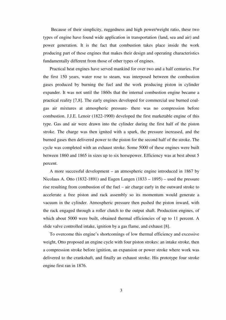
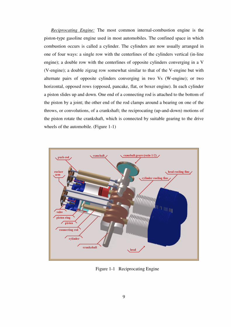
Reciprocating Engine: The most common internal-combustion engine is the
piston-type gasoline engine used in most automobiles. The confined space in which
combustion occurs is called a cylinder. The cylinders are now usually arranged in
one of four ways: a single row with the centerlines of the cylinders vertical (in-line
engine); a double row with the centerlines of opposite cylinders converging in a V
(V-engine); a double zigzag row somewhat similar to that of the V-engine but with
alternate pairs of opposite cylinders converging in two Vs (W-engine); or two
horizontal, opposed rows (opposed, pancake, flat, or boxer engine). In each cylinder
a piston slides up and down. One end of a connecting rod is attached to the bottom of
the piston by a joint; the other end of the rod clamps around a bearing on one of the
throws, or convolutions, of a crankshaft; the reciprocating (up-and-down) motions of
the piston rotate the crankshaft, which is connected by suitable gearing to the drive
wheels of the automobile. (Figure 1-1)
Figure 1-1 Reciprocating Engine
10
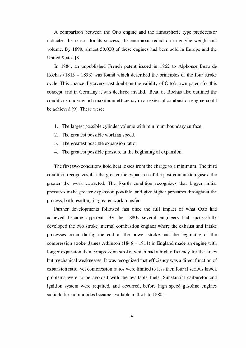
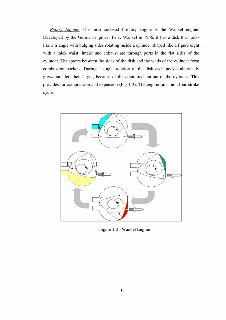
Rotary Engine: The most successful rotary engine is the Wankel engine.
Developed by the German engineer Felix Wankel in 1956, it has a disk that looks
like a triangle with bulging sides rotating inside a cylinder shaped like a figure eight
with a thick waist. Intake and exhaust are through ports in the flat sides of the
cylinder. The spaces between the sides of the disk and the walls of the cylinder form
combustion pockets. During a single rotation of the disk each pocket alternately
grows smaller, then larger, because of the contoured outline of the cylinder. This
provides for compression and expansion (Fig 1-2). The engine runs on a four-stroke
cycle.
Figure 1-2 Wankel Engine
11
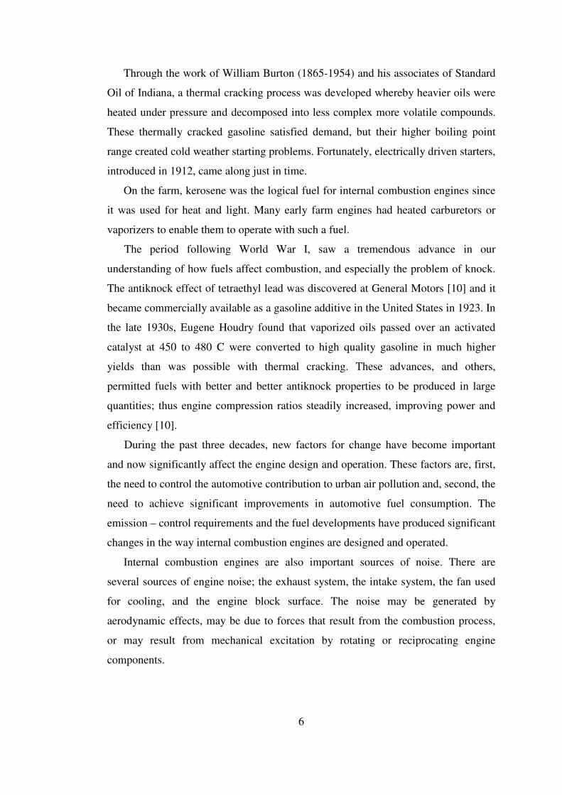
• Working Cycle. Four stroke cycle: naturally aspirated, supercharged and turbo
charged, two stroke cycle: crankcase scavenged, supercharged, turbocharged.
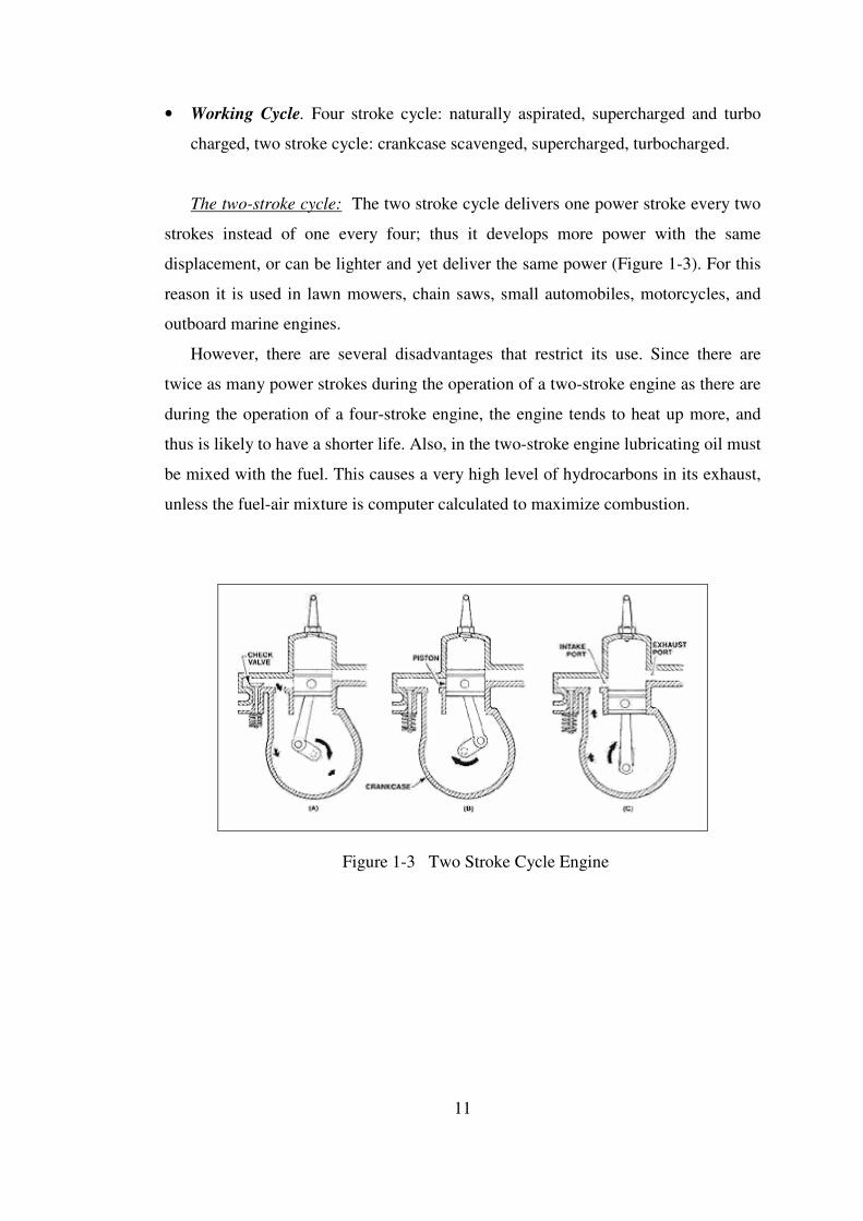
The two-stroke cycle: The two stroke cycle delivers one power stroke every two
strokes instead of one every four; thus it develops more power with the same
displacement, or can be lighter and yet deliver the same power (Figure 1-3). For this
reason it is used in lawn mowers, chain saws, small automobiles, motorcycles, and
outboard marine engines.
However, there are several disadvantages that restrict its use. Since there are
twice as many power strokes during the operation of a two-stroke engine as there are
during the operation of a four-stroke engine, the engine tends to heat up more, and
thus is likely to have a shorter life. Also, in the two-stroke engine lubricating oil must
be mixed with the fuel. This causes a very high level of hydrocarbons in its exhaust,
unless the fuel-air mixture is computer calculated to maximize combustion.
Figure 1-3 Two Stroke Cycle Engine

12
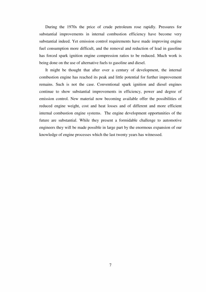
Four Stroke Engine: In most engines, a single cycle of operation (intake,
compression, power, and exhaust) takes place over four strokes of a piston, made in
two engine revolutions (Figure 1-4). When an engine has more than one cylinder the
cycles are evenly staggered for smooth operation, but each cylinder will go through a
full cycle in any two engine revolutions. When the piston is at the top of the cylinder
at the beginning of the intake stroke, the intake valve opens and the descending
piston draws in the air-fuel mixture.
At the bottom of the stroke the intake valve closes and the piston starts upward
on the compression stroke, during which it squeezes the air-fuel mixture into a small
space at the top of the cylinder. Just before the piston reaches the top again, the
spark plug fires, igniting the air-fuel mixture (alternatively, the heat of compression
ignites the mixture). The mixture on burning becomes a hot, expanding gas forcing
the piston down on its power stroke. As the piston reaches the bottom, the exhaust
valve opens, allowing the piston to force the combustion products—mainly carbon
dioxide, carbon monoxide, nitrogen oxides, and unburned hydrocarbons—out of the
cylinder during the upward exhaust stroke.
Figure 1-4 Four Stroke Cycle Engine
13
• Valve or port design and location. Overhead valves, under-head valves, rotary
valves, cross scavenged porting, loop scavenged porting, through or uniflow
scavenged.
• Fuel. Gasoline (or petrol), fuel oil (or diesel), natural gas, liquid petroleum gas,
alcohols (methanol, ethanol), hydrogen, dual fuel.
The diesel engine: The diesel engine differs from the gasoline engine in that the
ignition of fuel is caused by compression of air in its cylinders instead of by a spark:
the high compression ratio allows the air in the cylinder to become hot enough to
ignite the fuel. Because of the high temperatures of operation, a diesel engine must
be water-cooled. The speed and power of the diesel are controlled by varying the
amount of fuel injected into the cylinder, not the amount of air admitted as in the
gasoline engine.
Diesel engines are generally heavier, noisier and more powerful at lower speeds
than gasoline engines. They are also more fuel-efficient in some circumstances and
are used in heavy road-vehicles, some automobiles, ships and some locomotives and
light aircraft. Gasoline engines are used in most other road-vehicles including most
cars, motorcycles and mopeds. Both gasoline and diesel engines produce significant
emissions.
There are also engines that run on hydrogen, methanol, ethanol, liquefied
petroleum gas (LPG) and bio-diesel. Paraffin and Tractor vaporizing oil (TVO)
engines are no longer seen.
14
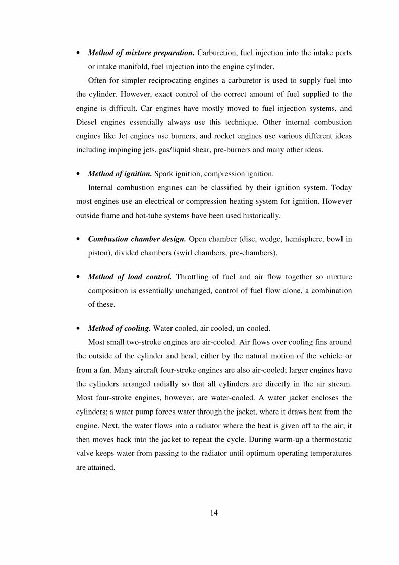
• Method of mixture preparation. Carburetion, fuel injection into the intake ports
or intake manifold, fuel injection into the engine cylinder.
Often for simpler reciprocating engines a carburetor is used to supply fuel into
the cylinder. However, exact control of the correct amount of fuel supplied to the
engine is difficult. Car engines have mostly moved to fuel injection systems, and
Diesel engines essentially always use this technique. Other internal combustion
engines like Jet engines use burners, and rocket engines use various different ideas
including impinging jets, gas/liquid shear, pre-burners and many other ideas.
• Method of ignition. Spark ignition, compression ignition.
Internal combustion engines can be classified by their ignition system. Today
most engines use an electrical or compression heating system for ignition. However
outside flame and hot-tube systems have been used historically.
• Combustion chamber design. Open chamber (disc, wedge, hemisphere, bowl in
piston), divided chambers (swirl chambers, pre-chambers).
• Method of load control. Throttling of fuel and air flow together so mixture
composition is essentially unchanged, control of fuel flow alone, a combination
of these.
• Method of cooling. Water cooled, air cooled, un-cooled.
Most small two-stroke engines are air-cooled. Air flows over cooling fins around
the outside of the cylinder and head, either by the natural motion of the vehicle or
from a fan. Many aircraft four-stroke engines are also air-cooled; larger engines have
the cylinders arranged radially so that all cylinders are directly in the air stream.
Most four-stroke engines, however, are water-cooled. A water jacket encloses the
cylinders; a water pump forces water through the jacket, where it draws heat from the
engine. Next, the water flows into a radiator where the heat is given off to the air; it
then moves back into the jacket to repeat the cycle. During warm-up a thermostatic
valve keeps water from passing to the radiator until optimum operating temperatures
are attained.
15
1.3 Thermodynamic Cycles of Engines
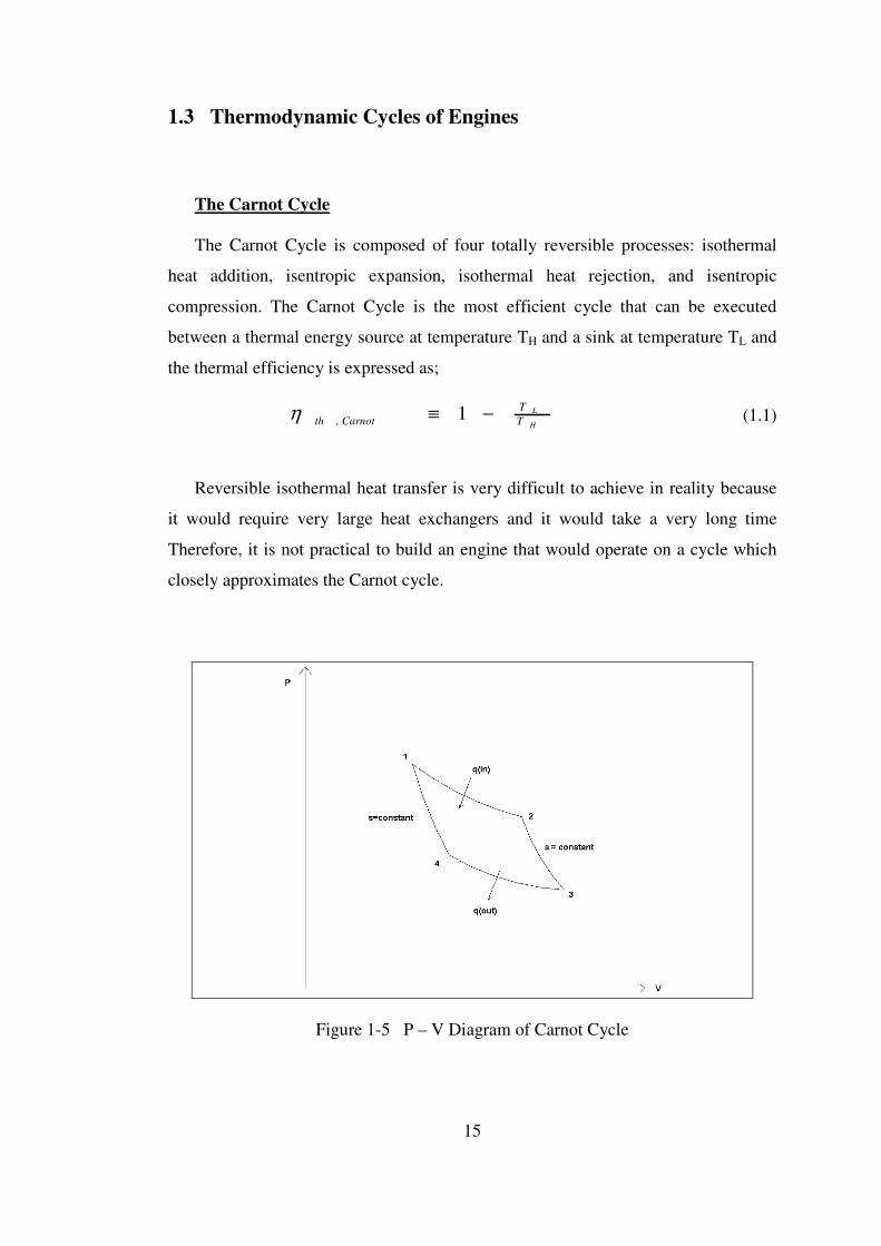
The Carnot Cycle
The Carnot Cycle is composed of four totally reversible processes: isothermal
heat addition, isentropic expansion, isothermal heat rejection, and isentropic
compression. The Carnot Cycle is the most efficient cycle that can be executed
between a thermal energy source at temperature TH and a sink at temperature TL and
the thermal efficiency is expressed as;
H
L
T
T
Carnotth −≡ 1,η (1.1)
Reversible isothermal heat transfer is very difficult to achieve in reality because
it would require very large heat exchangers and it would take a very long time
Therefore, it is not practical to build an engine that would operate on a cycle which
closely approximates the Carnot cycle.
Figure 1-5 P – V Diagram of Carnot Cycle

16
The Otto Cycle
The Otto Cycle is the ideal cycle for spark ignition reciprocating engines. It
consists of four internally reversible processes; isentropic compression, constant
volume heat addition, isentropic expansion and constant volume heat rejection. In
most spark ignition engines, the piston executes four complete strokes within the
cylinder, and the crankshaft completes 2 revolutions for each thermodynamic cycle.
These engines are called four-stroke internal combustion engines. The thermal
efficiency of the cycle is expressed as;
1
1, 1 −−≡ krOttothη (1.2)
where,
v
p
C
Ck
V
Vr ≡≡ ;
min
max (1.3)
Figure 1-6 P – V Diagram of Otto Cycle

17
The Diesel Cycle
The Diesel Cycle is the ideal cycle for compression ignition reciprocating
engines. It consists of four internally reversible processes; isentropic compression,
constant pressure heat addition, isentropic expansion and constant volume heat
rejection. The thermal efficiency of the cycle is expressed as;
−
−−≡ −
)1(
11 1
1,
c
k
c
rDieselthrk
rkη (1.4)
where,
2
3
min
max ;;V
Vr
C
Ck
V
Vr c
v
p≡≡≡ (1.5)
Figure 1-7 P – V Diagram of Diesel Cycle
18
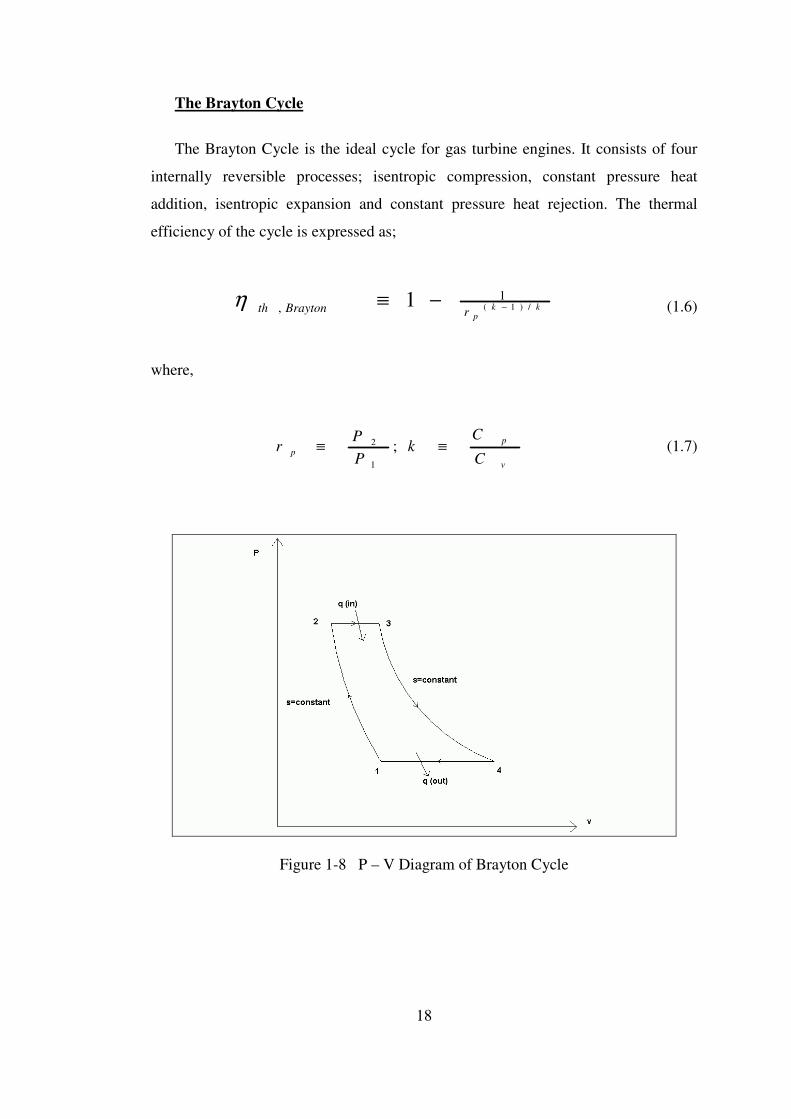
The Brayton Cycle
The Brayton Cycle is the ideal cycle for gas turbine engines. It consists of four
internally reversible processes; isentropic compression, constant pressure heat
addition, isentropic expansion and constant pressure heat rejection. The thermal
efficiency of the cycle is expressed as;
kkprBraytonth /)1(
1, 1 −−≡η (1.6)
where,
v
p
pC
Ck
P
Pr ≡≡ ;
1
2 (1.7)
Figure 1-8 P – V Diagram of Brayton Cycle
19
1.4 Rotary Engine Development
The rotary combustion engine must not be confused with "rotary" aircraft engines
which are piston cylinders arranged in a circle. The whole engine rotates. They came
into vogue in the First World War.
There are three main types of true rotary engines:
1. Wankel types based on eccentric rotors,
2. Scissor action types using vanes or pistons, and
3. Revolving block types ('cat and mouse' type).
Engines are closely related to pumps and compressors: the former drives and the
latter are driven.
Designs for rotary engines were proposed as early as 1588 by Ramelli, though it
took the development of the Otto cycle engine in 1876 and the advent of the
automobile in 1896 to set the stage for a proper rotary combustion engine.
Furthermore, it took Felix Wankel to catalogue and organizes 862 configuration
pairs, of which 278 are impractical. Wankel investigated 149. Prior to 1910, more
than 2000 patents for rotary pistons were filed [11].
Other early designs were made by Huygens in 1673 and Kepler. James Watt
made a rotary piston steam engine in 1759, as did Ericsson. The American John
Cooley made an invention of a sort of reverse Wankel in 1903, which Umpleby
applied to internal combustion in 1908, but never developed successfully. Some
people report that Elwood Haynes invented one in 1893, but I think they are
confusing it with his invention of a "rotary valve gas engine" in 1903. Frenchman
Sensaud de Lavaud obtained a patent for a four phase rotary piston engine in 1938,
two years after Felix Wankel. There were also designs by Pappenheim, Hornblower,
Murdoch, Bramah, Flint, Poole, Wright, Marriott, Trotter, Galloway, Parsons, Roots,
Wallinder, Skoog, Baylin, Larsen, Ljungström, Behrens, Maillard, and Jernaes.
Marsh has made a good summary with diagrams [13].
20
1.5 Reciprocating Versus Rotary Engines
The advantages and the disadvantages of the reciprocating and rotary engines are
summarized as follows;
Disadvantages of Reciprocating Engines
• Reciprocating motion of piston engine require inertial change of rotating mass of
pistons, rods, assembly. (Power Loss)
• Together with inertial changes of valves, springs, lifters, rocker arms, push rods.
(Additional Loss)
• Mechanical complexity.
• Include many moving parts lead to fatigue or wear.
• Large number of parts thus, large inertia mass change. (Power loss)
• Frictional loss between those parts. (Power loss)
• Expensive to manufacture and maintain equipment for large number of moving
parts.
• Low torque, high rpm machine. (Highest internal pressure at lowest torsional
moment in piston).
• Transmissions are needed to amplify the low torque which is weight, complexity,
additional power requirement.
• Expansion volume is not equal to compression volume. (combustion heat the gas,
thus increasing the expansion volume beyond initial volume) Relatively high-
pressure combustion gasses are exhausted without performing any useful work.
• Leakage of pressurized gas between high and low pressure sides around pistons
and inlet and exhaust parts.
• Lack of design diversity in engine industry. Internal combustion engine itself is
incapable of functioning as an air compressor, a vacuum pump, external
combustion engine, water pump, and a drive turbine for expandable gas.
21
Advantages of Rotary Engines
• The main advantage is the high power to weight ratio.
• Light weight and compact.
• Smooth: no reciprocating motion.
• All the parts in a rotary engine spin continuously in one direction, rather than
violently changing directions like the pistons in a conventional engine do. Rotary
engines are internally balanced with spinning counterweights that are phased to
cancel out any vibrations.
• Extended power "stroke" rotation of the output shaft: 270 degrees vs. the 180
degrees of a piston.
• Fewer moving parts: no valves, connecting rods, cams, timing chains. Intake and
exhaust timing are accomplished directly by the motion of the rotor.
• Separation of combustion region from intake region is good for hydrogen fuel.
• Lower oxides of nitrogen (NOx) emissions.
Disadvantages of Rotary Engines
• High surface to volume ratio in combustion chamber is less thermodynamically
efficient. The Wankel's long and narrow chamber makes for long flame travel,
but this is countered by the Mazda's two spark plugs (three on some racing
engines).
• Higher fuel consumption in naive designs. This is relative to the application
because the high power of the engine must be considered. Thus Mazda has been
successful with the RX-7 sports car, where its fuel economy is comparable to
other cars in its class. Only 16 years after the first engine ran, the 1973 oil crisis
devastated the RCE before it had sufficiently developed to become more
economical. Thus the engine has a more negative reputation regarding fuel
consumption than is actually deserved.
• The manufacturing costs can be higher, mostly because the number of these
engines produced is not as high as the number of piston engines.
22
1.6 Characteristics of the Novel Rotary Engine
1.6.1 Improved Thermodynamic Cycle
One of the main characteristic of the designed engine is the increased the
thermal efficiency above the reciprocating engines. This is achieved by
implementing a new thermodynamic cycle and by realizing high compression ratios
with less shaft power input within the working crescent shape cavity. This is
achieved by the gradual and smooth work of the rotor and the sliding vane against
the harmonious shape of the cycloid housing inner peripheral and the rotor side wall.
The designed novel rotary engine combines the advantages of Otto and Diesel
cycles at intake, compression and combustion phases of the thermodynamic cycle,
the engine also achieves an expanded power stroke that improves power extraction
and efficiency. With a proper thermodynamic and geometrical match of the
compressor and turbine working chambers, the expansion process can be improved
and lower exhaust pressure and temperature levels can be achieved.
1.6.2 Separate Compression and Expansion Chambers
Actually, almost all rotary vane type engines produce very high torque because
the combusted gas expands right against the hot section vane which also constitutes
the arm length of the generated power torque. Therefore, not only is the crankshaft
unnecessary for rotary engines, but when comparing engines of equal volumes, the
power leverage on the drive shaft of a rotary engine is greater than that of a
corresponding reciprocating engine.

23
1.6.3 Limited Peak and Extended Expansion Thermodynamic Cycle
The designed novel rotary engine combines the advantages of Otto and Diesel
cycles at intake, compression and combustion phases of the thermodynamic cycle. It
is well known that for a given compression ratio, the ideal Otto cycle currently
provides the most efficient combustion / expansion process since it combines high
peak temperature during the isochoric (constant volume) heat addition, while still
keeping an acceptable mean chamber temperature. However, high peak combustion
temperatures can cause auto-ignition of a portion of fuel-air mixture, resulting in
engine knocks. Diesel is an improvement of the Otto cycle as it provides higher
useful compression ratios and isobaric (constant pressure) heat addition and do not
have knock problem as air alone is present during the compression process. The high
compression ratios make Diesel engines more fuel efficient but for this same reason,
they also become much heavier.
Compared to the Otto cycle, Diesel cycle also delivers less power for the same
displacement. For the compression and combustion phases of the cycle, the ideal
would be to follow a limited combustion pressure cycle that would first use a
combined isochoric heat addition followed by isobaric and / or isothermal heat
additions. Such hybrid engine process has been developed but they have proven
impractical.
The designed novel rotary engine naturally follows the above-described limited
peak cycle during the intake, compression and the two-step (isochoric, isobaric and /
or isothermal) combustion phases.
Besides limiting the peak combustion pressures and temperatures within the
rotary engine, the engine also achieves an expanded power stroke that improves
power extraction by at least 10% and efficiency by more than 15%.
The designed novel engine configuration can be rearranged to form other
thermodynamic cycles for a variety of power generation, ventilation, fluid pump,
pressurization, heating and cooling applications.

24
1.6.4 Improved Sealing and Avoiding Wear.
Another characteristic of the designed engine is the decreased wear. The wear is
minimized through the incorporation of the pivot axle vane retention mechanism and
by providing efficient oil lubrication. The operational and maintenance costs are also
minimized as the engine is an intermittent combustion engine with allows two
combustion cycle per rotor revolution, thus allowing the hot section material to
remain within an acceptable temperature levels. The new thermodynamic cycle has a
shaved top pressure level that also limits the maximum operational temperature that
is reached. Finally effective oil and water jacket cooling system is also implemented
so as to provide a longer operational schedule between consecutive maintenance
stops.
In the designed novel rotary engine, the intermediary cylindrical slides are
eliminated all together as the vane tips are always in a natural contact with the
housing inner peripheral. The basic reason for this natural contact is that the housing
inner peripheral is non-circular and has a cycloid shape that accommodates well an
eccentrically placed sliding vane of fixed length.
The cycloid peripheral is a unique shape, mainly depending on 4 parameters: the
radial offset distance between the rotor center and the center of the chamber and, the
sliding vane length, the seal height and the seal spring properties.
The dynamic and thermal loading behavior of the seal spring under rotation and
the peripheral temperature differences, dictate a cycloid shape different than those
given by exact equations of previous arts
The geometry has a good sealing capability as the rotating vane fits well the
chamber cavity at all rotational angles.
Another characteristic of the designed engine is the decreased leakage. This has
been achieved by the use of multi channel seals and by avoiding any use of complex
mechanism. Therefore a compact, simple and reliable system was achieved.
25
1.7 Outline of the Thesis
In chapter two, the novel thermodynamic cycle of the novel rotary engine is
being introduced. The P-V and T-S diagrams, basic equations and the efficiency
calculations are given. Also in chapter two, the thermodynamic design code written
to dimension the engine is explained and the dimension calculations of the novel
engine are given.
The third chapter consists of the structural and mechanical design of the novel
rotary engine with the dimensions taken from the thermodynamic design code. The
structural analysis of the critical components and the material selection are explained
and the results are presented. This chapter also includes brief explanation of the
auxiliary systems (fuel, lubrication, ignition and cooling) of the engine.
The fourth chapter includes information on the test study of the prototype of the
engine. Compressor, turbine and combustion chamber component tests and their
results are presented.
In chapter five, all the work done in this thesis is summarized, the future work for
this study is given and the application of this thesis in the industry is explained. A
discussion of the results and the conclusion are also presented in this chapter.

26
CHAPTER 2
THERMODYNAMIC DESIGN OF THE NOVEL
ROTARY ENGINE
2.1 Novel Thermodynamic Cycle
It is well known that for a given compression ratio, the ideal Otto cycle currently
provides the most efficient combustion / expansion process as it combines high peak
temperature during the isochoric (constant volume) heat addition, while still keeping
an acceptable mean chamber temperature. However, high peak combustion
temperatures can cause auto-ignition of a portion of fuel-air mixture, resulting in
engine knocks. Diesel is an improvement of the Otto cycle as it provides higher
useful compression ratios and isobaric (constant pressure) heat addition and do not
have knock problem as air alone is present during the compression process. The high
compression ratio makes Diesel engines more fuel-efficient but for this same reason,
they also become much heavier. Compared to the Otto cycle, Diesel cycle also
delivers less power for the same displacement. For the compression and combustion
phases of the cycle, the ideal would be to follow a limited combustion pressure cycle
that would first use a combined isochoric heat addition followed by isobaric and/or
isothermal heat additions. As mentioned in a prior patent, such hybrid engine process
has been developed (Texaco TCCS, Ford PROCO, Ricardo, MAN-FM and KHD-
AD) but they have been proven impractical. This is probably because the piston
engine was forced unsuccessfully to follow the hybrid Otto-Diesel thermodynamic
cycle.

27
It is important to understand that, not only the thermodynamics but also the
kinematics and the fluid mechanics are involved when adapting a thermodynamic
cycle to an engine.
The rotary vane engine designed in this thesis naturally follows the new limited
peak thermodynamic cycle (Figure 2-1 and 2-2).
This novel cycle [17], combines the advantages of Otto and Diesel cycles at
intake, compression and combustion phases by limiting the peak combustion
temperature. The present cycle also has an expanded power stroke. With a proper
thermodynamic and geometrical match of the compressor and turbine working
chambers volumes, ambient exhaust pressure levels can be achieved. These features
explained below, fundamentally differ from previous thermodynamic cycles.
2.1.1 P – V, T – S Diagrams
Figure 2-1 Novel Thermodynamic Cycle (P – V) for Rotary Vane Engine

28
Figure 2-2 Novel Thermodynamic Cycle (T – S) for Rotary Vane Engine
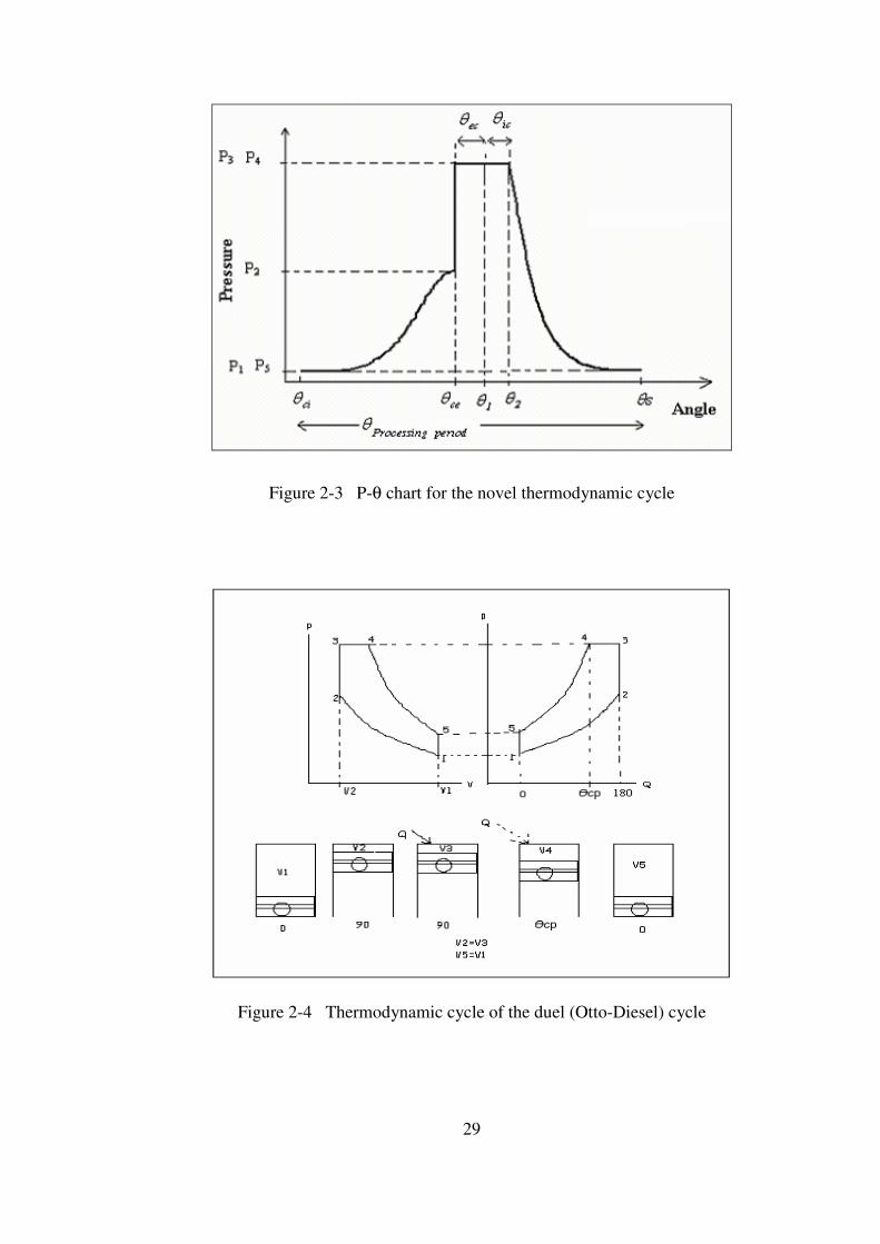
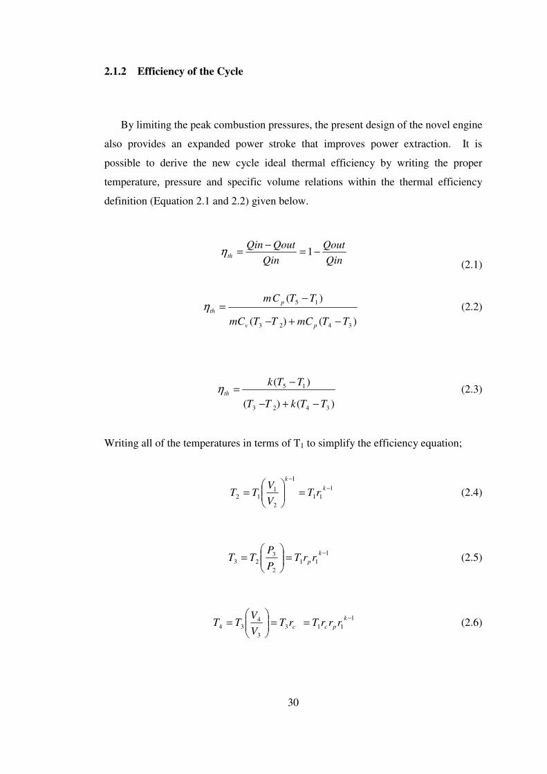
Firstly, the combustion phase is divided into two parts; θec, the external
combustion phase occurring in a burner placed midway between the compressor and
turbine chambers, and θic, the internal combustion phase which occurs within the
turbine.(Figure 2-3) In the designed novel engine, θec can arbitrarily take very large
angle bracket values up to 180°. This angle bracket by far exceeds those allowed in a
piston engine where the combustion process is generally squeezed down to a narrow
angle bracket (θcp-90o, given in Figure 2-4) not exceeding 30°. This shows that the
designed novel engine operating thermodynamic cycle allows ample time for
enhanced fuel-air mixing and also allows wave compression within the burner prior
to let the gas expands through a Laval nozzle like crescent shape rotary turbine area.
The ample time given for the combustion chamber is the key to a successful lean
combustion, further improving the thermal efficiency and protecting the turbine vane
and the rotor from high temperatures spots. Secondly, the rotary engine allows 2
firings per revolution. Therefore, at every time within the engine two overlapping
power stroke exists forming a powerful torque couple that acts on both sides of the
turbine vane. The strong torque couple is driven by gas that expands up to ambient
pressures within the turbine chamber.
29
Figure 2-3 P-θ chart for the novel thermodynamic cycle
Figure 2-4 Thermodynamic cycle of the duel (Otto-Diesel) cycle
30
2.1.2 Efficiency of the Cycle
By limiting the peak combustion pressures, the present design of the novel engine
also provides an expanded power stroke that improves power extraction. It is
possible to derive the new cycle ideal thermal efficiency by writing the proper
temperature, pressure and specific volume relations within the thermal efficiency
definition (Equation 2.1 and 2.2) given below.
Qin
Qout
Qin
QoutQinth −=
−= 1η
(2.1)
)()(
)(
3423
15
TTmCTTmC
TTCm
pv
p
th
−+−
−=η (2.2)
)()(
)(
3423
15
TTkTT
TTkth
−+−
−=η (2.3)
Writing all of the temperatures in terms of T1 to simplify the efficiency equation;
1
11
1
2
1
12
−
−
=
=
k
k
rTV
VTT (2.4)
1
11
2
3
23
−=
=
k
p rrTP
PTT (2.5)
1
113
3
434
−==
=
k
pcc rrrTrTV
VTT (2.6)
31
11
5
445
−−
=
kk
V
VTT (2.7)
k
p
kkk
rrP
P
P
P
P
P
P
P
rV
V
1
1
1
3
2
2
1
1
4
1
1
4
5
25
4 111
=
=
=
== (2.8)
Inserting the equation. 2.8 into the equation. 2.7;
k
pc
k
pc rrTrrrrTT/1
1
1
2115 )/( == − (2.9)
Therefore;
( ) ( )1
1
1
11
1
1
1
11
1
2
11 1
1−−−−
−
−+−
−
−=k
p
k
pc
kk
p
k
pc
th
rrrrrkTrrrT
rr
rrkT
η (2.10)
( ) ( )( )
−+−
−−=
− 11
11
1
1
1 cpp
kpc
kthrkrr
rr
r
kη (2.11)
where;
3
4
V
Vrc =
2
3
P
Prp =
2
11
V
Vr =
(2.12)

32
Comparing with the Otto cycle thermal efficiency given below (Equation 2.13), it
is seen that the new thermodynamic cycle thermal efficiency has a much higher
degree of freedom as Equation 2.11 is defined in terms of 3 variables (namely rL, rp,
rc )all defined above, compared to only one variable r = V1 / V2 for the Otto cycle.
As temperature upper limit restricts the increase of Otto cycle volume ratio r, the
Otto thermal efficiency reaches a modest peak value. As for the diesel cycle thermal
efficiency given below (Equation 2.14), it is even lower because the term A is bigger
than 1.
1
11
−−=
kOttothr
η (2.13)
Ar
kDieselth 1
11
−−=η (2.14)
As the bracketed term in Equation 2.11 is always less than 1, the new
thermodynamic cycle thermal efficiency is guaranteed to be always bigger than those
pertaining to Otto and Diesel cycles.
33
2.2 Dimensioning the Engine
2.2.1 Thermodynamic Design Code
This thermodynamic design code is written to calculate the necessary geometry
of the novel rotary engine for the desired performance values and to determine the
thermodynamic properties during compression, combustion and expansion phases
which will be used in the structural analysis of the engine parts.
Firstly, performance parameters (power output, rpm) of the novel rotary engine
that will be designed are made certain. After describing the performance of the
engine, the critical parameters of the engine such as maximum temperature during
combustion, fuel to air ratio, compression ratio are specified. By processing the basic
inputs (atmospheric properties, thermodynamic constants and desired engine
properties) and the geometric inputs (basic dimensions of the engine), the code
calculates the properties for the compression phase, constant volume and constant
pressure combustion phases and the expansion and exhaust phases, and matches the
compressor and turbine geometry. After finalizing the engine geometry, the code
makes the necessary performance calculations to determine the power output, and
thermal efficiency. If the required power output is not managed, then the compressor
geometry is revised and the compressor – turbine matching is remade. After
finalizing the engine geometry, the thermal efficiency and the thermal properties
during compression, combustion and expansion phases which will be used in the
structural analysis of the engine parts are calculated.
The flowchart of the thermodynamic code is given in Figure 2-5.
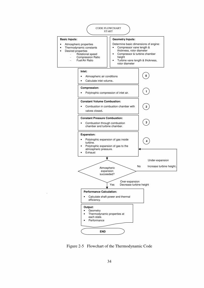
34
Under-expansion
No Increase turbine height.
Over-expansion
Yes Decrease turbine height .
Figure 2-5 Flowchart of the Thermodynamic Code
CODE FLOWCHART
START
Geometry Inputs:
Determine basic dimensions of engine:
• Compressor vane length & thickness, rotor diameter
• Compressor & turbine chamber height
• Turbine vane length & thickness, rotor diameter
Inlet:
• Atmospheric air conditions
• Calculate inlet volume.
Compression:
• Polytrophic compression of inlet air. 1
Constant Volume Combustion:
• Combustion in combustion chamber with
valves closed. 2
Constant Pressure Combustion:
• Combustion through combustion chamber and turbine chamber.
0
Expansion:
• Polytrophic expansion of gas inside turbine.
• Polytrophic expansion of gas to the atmospheric pressure.
• Exhaust
3
4
Output:
• Geometry
• Thermodynamic properties at each state.
• Performance
END
Atmospheric expansion
succeeded?
Basic Inputs:
• Atmospheric properties
• Thermodynamic constants
• Desired properties - Rotational speed - Compression Ratio - Fuel/Air Ratio
Performance Calculation:
• Calculate shaft power and thermal efficiency.

35
DESCRIPTION OF THE THERMODYNAMIC CODE:
INPUTS
Table 2.1 Thermodynamic Code Basic Inputs
Cp Specific heat constant (constant pressure)
Cv Specific heat constant (constant volume)
P1 Atmospheric air pressure
T1 Atmospheric air temperature
1ρ Atmospheric air density
R Universal gas coefficient k Polytrophic expansion and compression constants
Cr Compression ratio
rpm Revolution per minute
far Fuel/Air ratio
hfu Fuel properties (Fuel enthalpy)
Geometrical properties
CALCULATIONS
• Compressor Inlet Volume and Inlet Air Properties Calculation
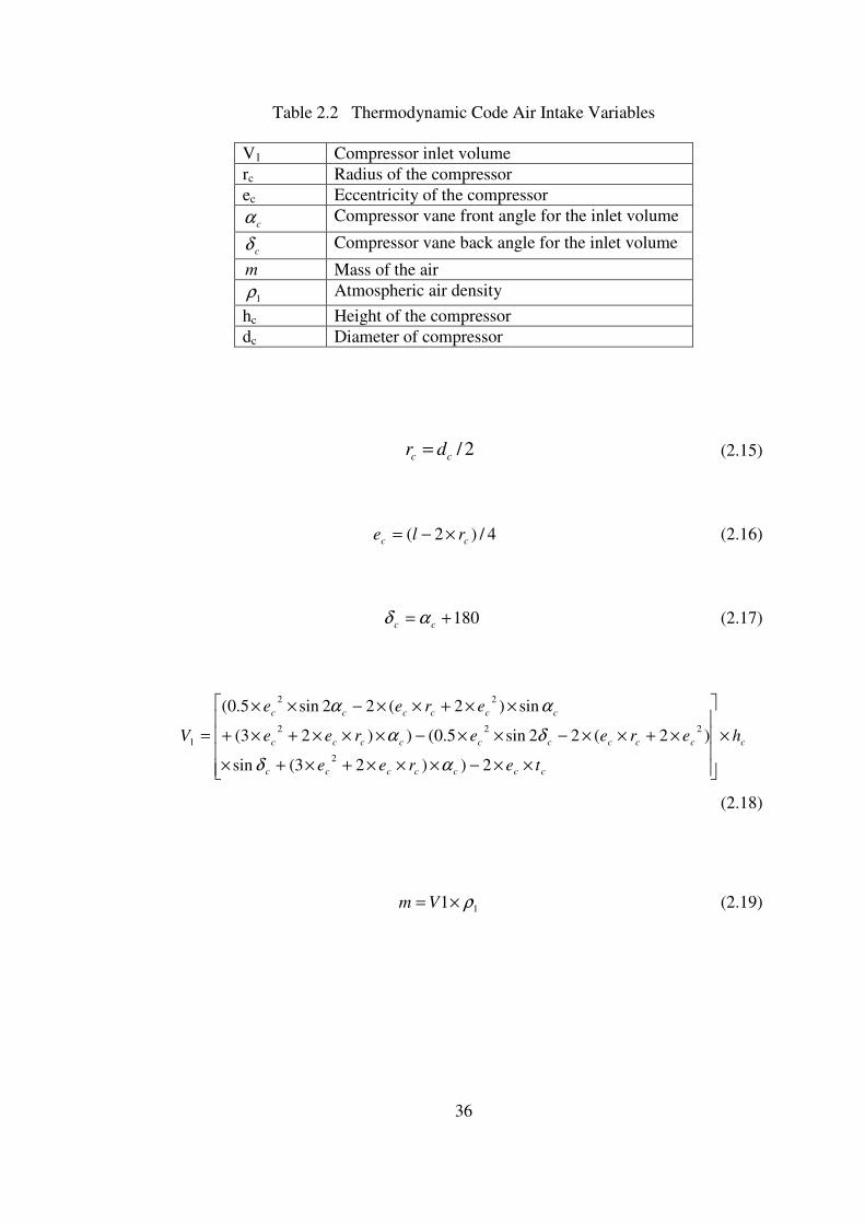
Figure 2-6 Compressor Air Intake Phase
36
Table 2.2 Thermodynamic Code Air Intake Variables
V1 Compressor inlet volume
rc Radius of the compressor
ec Eccentricity of the compressor
cα Compressor vane front angle for the inlet volume
cδ Compressor vane back angle for the inlet volume
m Mass of the air
1ρ Atmospheric air density
hc Height of the compressor
dc Diameter of compressor
2/cc dr = (2.15)
4/)2( cc rle ×−= (2.16)
180+= cc αδ (2.17)
c
ccccccc
ccccccccc
cccccc
h
teree
ereeree
eree
V ×
××−×××+×+×
×+××−××−×××+×+
××+××−××
=
2))23(sin
)2(22sin5.0())23(
sin)2(22sin5.0(
2
222
22
1
αδ
δα
αα
(2.18)
11 ρ×= Vm (2.19)

37
• Compression and Combustion Chamber Volume Calculation
Figure 2-7 Compression Phase
Table 2.3 Thermodynamic Code Compression Variables
P2 Air pressure after compression
T2 Air temperature after compression
2ρ Air density after compression
W2 Compression work
Cr Compression ratio
V2 Combustion chamber volume
rCVV /12 = (2.20)
12 PCPk
r ×= (2.21)
1
12
−×=
k
rCTT (2.22)
)/( 222 TRP ×=ρ (2.23)
260/*)( 212 ××−×= rpmmTTCW v (2.24)
38
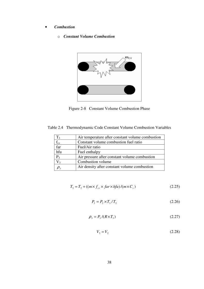
• Combustion
o Constant Volume Combustion
Figure 2-8 Constant Volume Combustion Phase
Table 2.4 Thermodynamic Code Constant Volume Combustion Variables
T3 Air temperature after constant volume combustion
fcv Constant volume combustion fuel ratio
far Fuel/Air ratio
hfu Fuel enthalpy
P3 Air pressure after constant volume combustion
V3 Combustion volume
3ρ Air density after constant volume combustion
)/()((23 vcv CmhfufarfmTT ××××+= (2.25)
2323 /TTPP ×= (2.26)
)/( 333 TRP ×=ρ (2.27)
23 VV = (2.28)
39
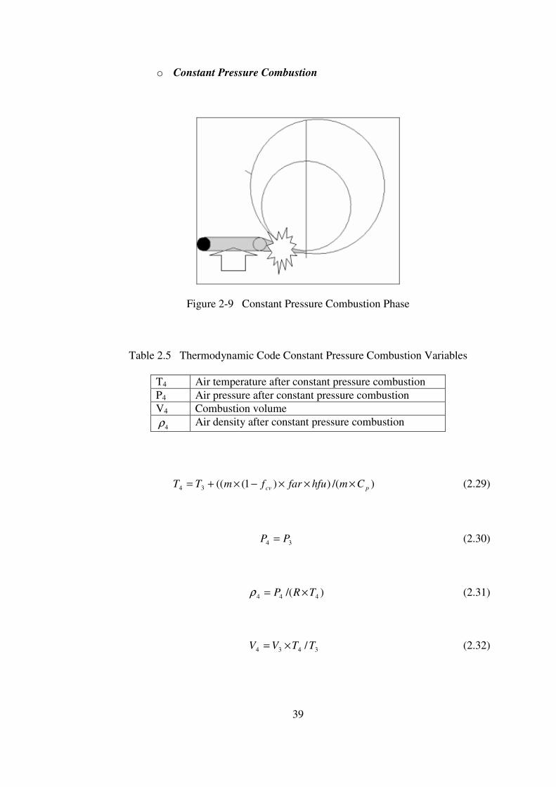
o Constant Pressure Combustion
Figure 2-9 Constant Pressure Combustion Phase
Table 2.5 Thermodynamic Code Constant Pressure Combustion Variables
T4 Air temperature after constant pressure combustion
P4 Air pressure after constant pressure combustion
V4 Combustion volume
4ρ Air density after constant pressure combustion
)/())1(((34 pcv CmhfufarfmTT ×××−×+= (2.29)
34 PP = (2.30)
)/( 444 TRP ×=ρ (2.31)
3434 /TTVV ×= (2.32)

40
• Turbine Expansion Volume and Air Properties After Expansion in the
Turbine Calculation
Figure 2-10 Turbine Expansion Phase
Table 2.6 Thermodynamic Code Expansion Variables
V5 Turbine inlet volume
rt Radius of the turbine
ht Estimated height of the turbine
et Eccentricity of the turbine
tα Turbine vane angle for the exhaust volume
5ρ Density of the air after expansion
W5 Expansion work
T5 Air temperature after expansion
P5 Air pressure after expansion
41
2/tt dr = (2.33)
4/)2( tt rle ×−= (2.34)
t
tttttt
tttttt
tttttttttt
h
teree
eree
reeeree
V ×
××−−×××+×+
−××+××−−××−
×××+×+××+××−××
=
2))180()23(
)180sin()2(2)180(2sin5.0(
))23(sin)2(22sin5.0(
2
22
222
5
α
αα
ααα
(2.35)
4545 )/( PVVPk ×= (2.36)
Checking P5 for 1 atm or not
If not increase or decrease the turbine height
If 1 atm then
1
5445 )/( −×= kVVTT (2.37)
)/( 552 TRP ×=ρ (2.38)
260/*)( 545 ××−×= rpmmTTCW v (2-39)
42
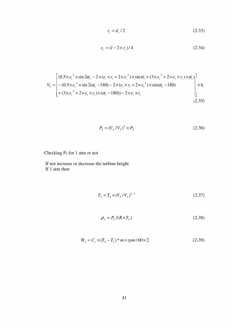
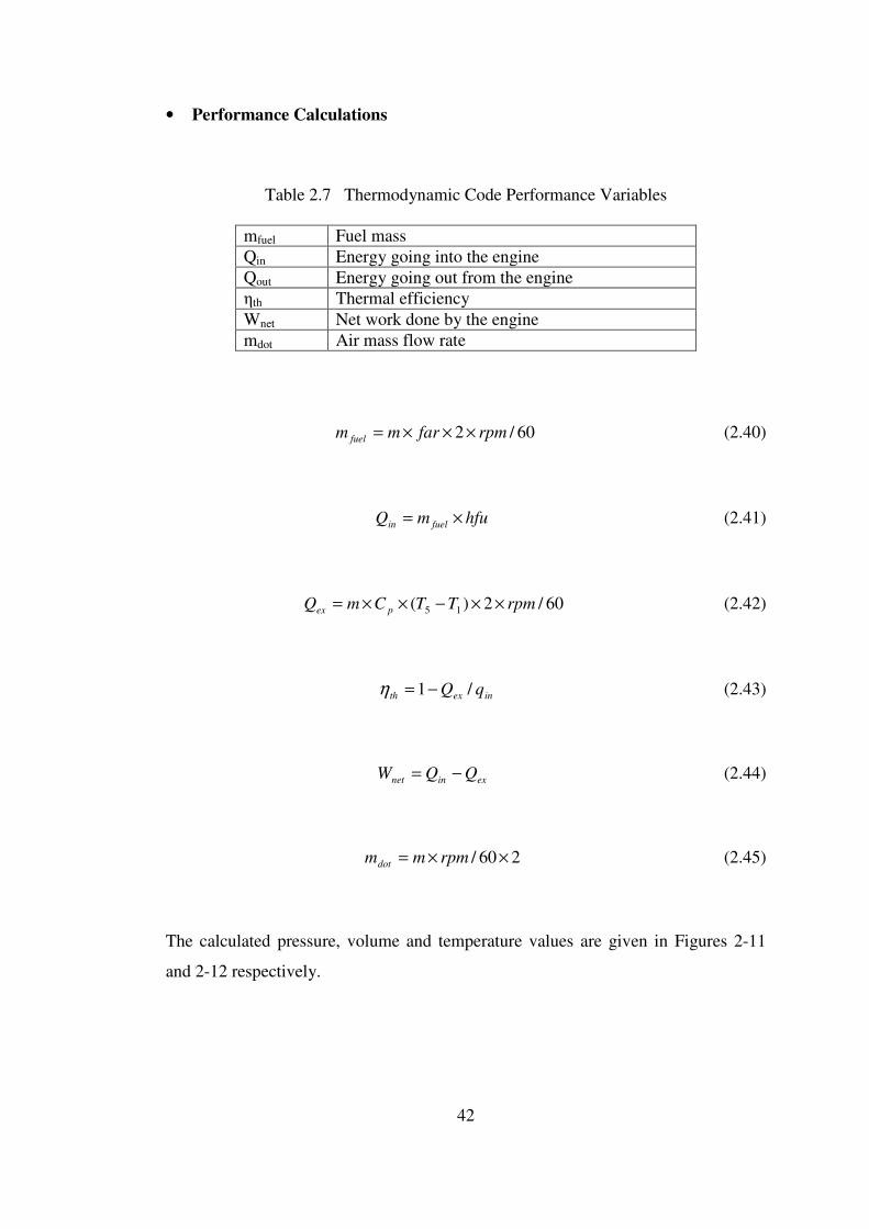
• Performance Calculations
Table 2.7 Thermodynamic Code Performance Variables
mfuel Fuel mass
Qin Energy going into the engine
Qout Energy going out from the engine
ηth Thermal efficiency
Wnet Net work done by the engine
mdot Air mass flow rate
60/2 rpmfarmm fuel ×××= (2.40)
hfumQ fuelin ×= (2.41)
60/2)( 15 rpmTTCmQ pex ××−××= (2.42)
inexth qQ /1−=η (2.43)
exinnet QQW −= (2.44)
260/ ××= rpmmmdot (2.45)
The calculated pressure, volume and temperature values are given in Figures 2-11
and 2-12 respectively.
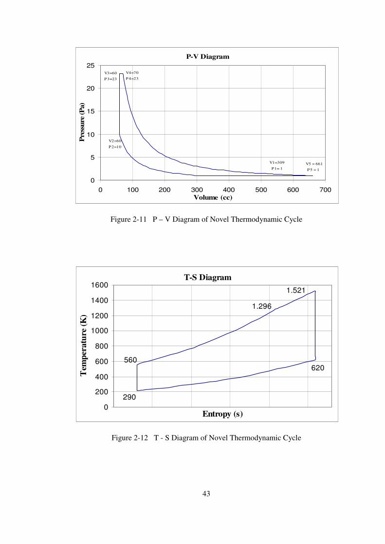
43
P-V Diagram
V2=60
P2=10
V3=60
P3=23
V4=70
P4=23
V5 = 661
P5 = 1
V1=309
P1= 1
0
5
10
15
20
25
0 100 200 300 400 500 600 700
Volume (cc)
Pre
ssure
(P
a)
Figure 2-11 P – V Diagram of Novel Thermodynamic Cycle
T-S Diagram
620
1.521
1.296
290
560
0
200
400
600
800
1000
1200
1400
1600
Entropy (s)
Tem
per
atu
re (
K)
Figure 2-12 T - S Diagram of Novel Thermodynamic Cycle
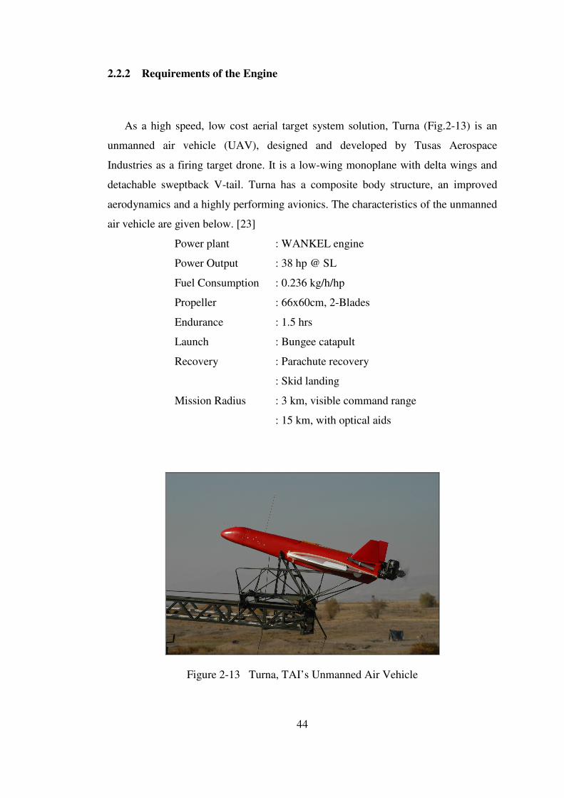
44
2.2.2 Requirements of the Engine
As a high speed, low cost aerial target system solution, Turna (Fig.2-13) is an
unmanned air vehicle (UAV), designed and developed by Tusas Aerospace
Industries as a firing target drone. It is a low-wing monoplane with delta wings and
detachable sweptback V-tail. Turna has a composite body structure, an improved
aerodynamics and a highly performing avionics. The characteristics of the unmanned
air vehicle are given below. [23]
Power plant : WANKEL engine
Power Output : 38 hp @ SL
Fuel Consumption : 0.236 kg/h/hp
Propeller : 66x60cm, 2-Blades
Endurance : 1.5 hrs
Launch : Bungee catapult
Recovery : Parachute recovery
: Skid landing
Mission Radius : 3 km, visible command range
: 15 km, with optical aids
Figure 2-13 Turna, TAI’s Unmanned Air Vehicle
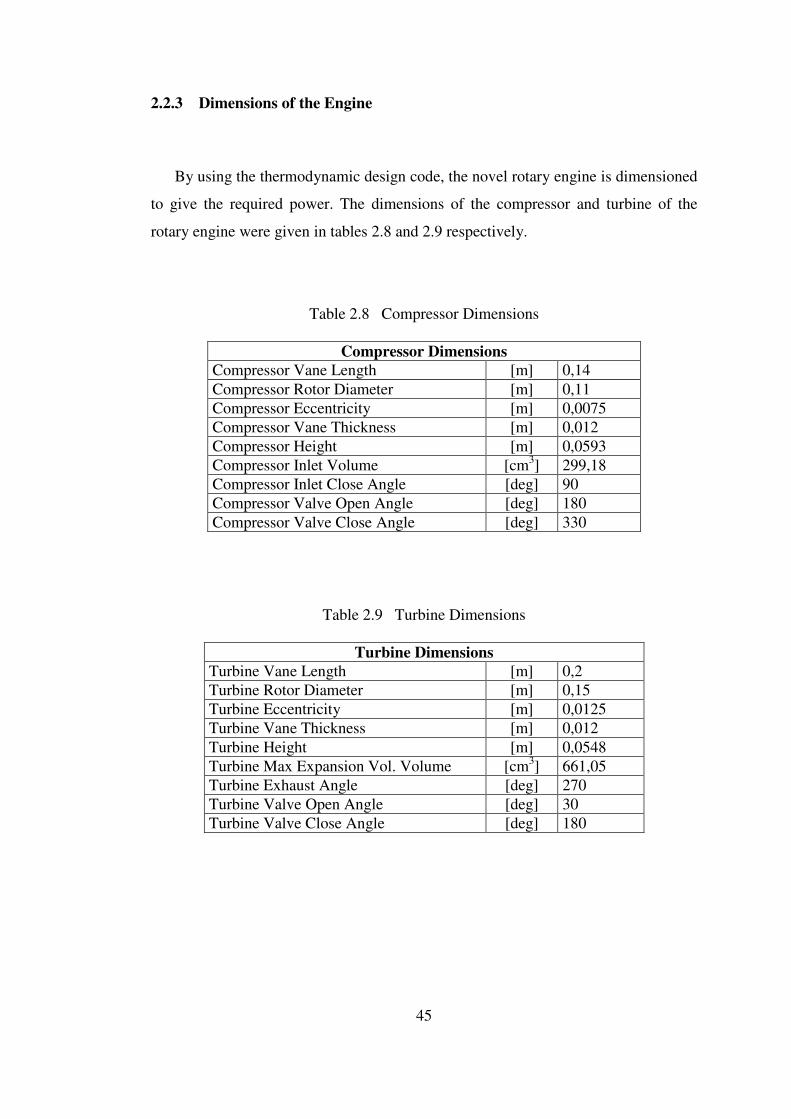
45
2.2.3 Dimensions of the Engine
By using the thermodynamic design code, the novel rotary engine is dimensioned
to give the required power. The dimensions of the compressor and turbine of the
rotary engine were given in tables 2.8 and 2.9 respectively.
Table 2.8 Compressor Dimensions
Compressor Dimensions
Compressor Vane Length [m] 0,14
Compressor Rotor Diameter [m] 0,11
Compressor Eccentricity [m] 0,0075
Compressor Vane Thickness [m] 0,012
Compressor Height [m] 0,0593
Compressor Inlet Volume [cm3] 299,18
Compressor Inlet Close Angle [deg] 90
Compressor Valve Open Angle [deg] 180
Compressor Valve Close Angle [deg] 330
Table 2.9 Turbine Dimensions
Turbine Dimensions
Turbine Vane Length [m] 0,2
Turbine Rotor Diameter [m] 0,15
Turbine Eccentricity [m] 0,0125
Turbine Vane Thickness [m] 0,012
Turbine Height [m] 0,0548
Turbine Max Expansion Vol. Volume [cm3] 661,05
Turbine Exhaust Angle [deg] 270
Turbine Valve Open Angle [deg] 30
Turbine Valve Close Angle [deg] 180
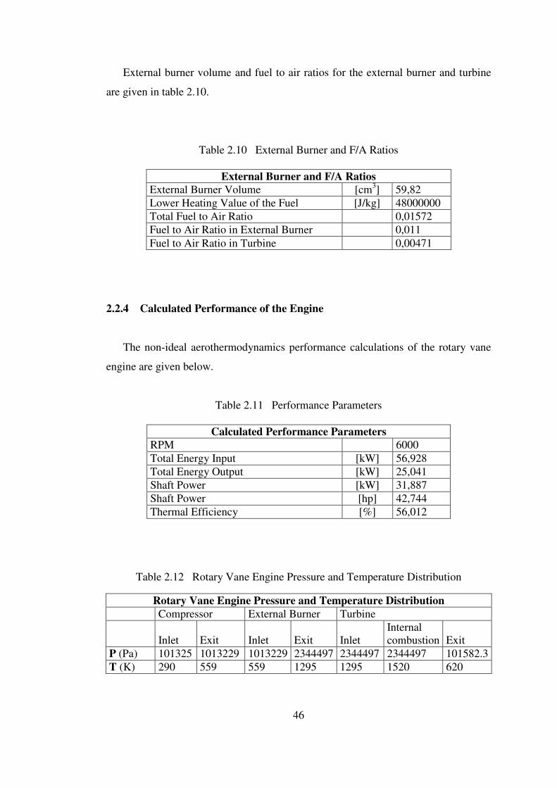
46
External burner volume and fuel to air ratios for the external burner and turbine
are given in table 2.10.
Table 2.10 External Burner and F/A Ratios
External Burner and F/A Ratios
External Burner Volume [cm3] 59,82
Lower Heating Value of the Fuel [J/kg] 48000000
Total Fuel to Air Ratio 0,01572
Fuel to Air Ratio in External Burner 0,011
Fuel to Air Ratio in Turbine 0,00471
2.2.4 Calculated Performance of the Engine
The non-ideal aerothermodynamics performance calculations of the rotary vane
engine are given below.
Table 2.11 Performance Parameters
Calculated Performance Parameters
RPM 6000
Total Energy Input [kW] 56,928
Total Energy Output [kW] 25,041
Shaft Power [kW] 31,887
Shaft Power [hp] 42,744
Thermal Efficiency [%] 56,012
Table 2.12 Rotary Vane Engine Pressure and Temperature Distribution
Rotary Vane Engine Pressure and Temperature Distribution
Compressor External Burner Turbine
Inlet Exit Inlet Exit Inlet
Internal
combustion Exit
P (Pa) 101325 1013229 1013229 2344497 2344497 2344497 101582.3
T (K) 290 559 559 1295 1295 1520 620

47
The temperature and pressure levels based on these calculations are given in table
2.12 A non-ideal thermal efficiency of 56,012% has been calculated. Calculated
performances of the rotary vane engine are compared with a UAV Engines Ltd. AR-
741 Wankel engine producing 38 kW shaft power at sea level. Figure 2-14 shows 67
% surplus in rotary power at low speeds and 48 % excess in rotary power at high
speeds. Best of all, the high improvement in the power performance is also
accompanied by a drop in specific fuel consumption (Figure 2-15). If the rotary vane
engine is used, a drop of 68% is expected at relatively low speeds and a drop of 66%
is expected at high speeds. A similar performance improvement is expected for
torque production (Figure 2-16). At low rpm, rotary vane engine torque production
is greater by 62% where as at high rpm values, torque is increased by 47%.
Wankel vs. Rotary Vane Engine Power
0
10
20
30
40
50
60
70
80
4000 5000 6000 7000 8000
RPM
BH
P
Rotary Vane Engine Wankel
Figure 2-14 Rotary Vane Engine Shaft Power vs. RPM
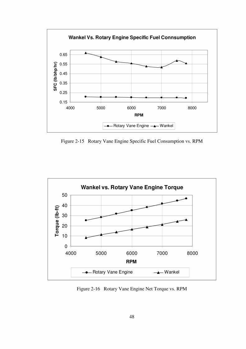
48
Wankel Vs. Rotary Engine Specific Fuel Connsumption
0.15
0.25
0.35
0.45
0.55
0.65
4000 5000 6000 7000 8000
RPM
SF
C (
lb/b
hp
/hr)
Rotary Vane Engine Wankel
Figure 2-15 Rotary Vane Engine Specific Fuel Consumption vs. RPM
Wankel vs. Rotary Vane Engine Torque
0
10
20
30
40
50
4000 5000 6000 7000 8000
RPM
To
rqu
e (
lb-f
t)
Rotary Vane Engine Wankel
Figure 2-16 Rotary Vane Engine Net Torque vs. RPM

49
Table 2.13 Comparison of Engines
Comparison of Engines Characteristics and Related Thermodynamic Cycles Engine Type
and
Thermodynami
c cycle
Wankel
Otto
Rotary Vane
New cycle
Piston
Otto
Piston
Diesel
Small Gas
turbine
(0-500 kW)
Brayton
Power
production
1 time per 1
revolution
2 times per 1
revolution
1 time per 2
revolutions
1 time per 2
revolutions Continuous
Thermal
efficiency Low Very high Average High Low
Expansion up
to ambient
pressure?
No Yes No No Yes
Maximum
engine
temperature
Very high
but
intermittent:
internal
combustion
engine
Limited and
intermittent:
External-
internal
combustion
engine
High but
intermittent
Limited and
intermittent:
internal
combustion
engine
Very high
and
continuous:
external
combustion
engine
Torque
production at
low RPM
Average Very high Low High Very low
Torque
production at
high RPM
Average Very high High High Very high
Number of
moving parts Low Low High High Very low
Can inlet,
compressor,
combustor,
turbine be
optimized
separately
No Yes No No Yes
Rotor dynamics
Off-center
rotation,
cyclic
acceleration
Quasi steady
rotation and
acceleration
Reciprocating
motion, high
unsteady
acceleration
Reciprocating
motion, high
unsteady
acceleration
Steady
rotation and
acceleration

50
CHAPTER 3
STRUCTURAL AND MECHANICAL DESIGN OF THE
NOVEL TURBO ROTARY ENGINE
3.1 Compressor Design
• The designed compressor of the novel turbo rotary engine is a sliding vane
compressor which is a positive displacement type rotary compressor. This
compressor uses a rotor equipped with a radially movable single sliding vane,
mounted eccentrically in a crescent shape cavity. The single vane is free to slide
in and out of the slot cut into the rotor. As the rotor rotates, both ends of the
sliding vane are extending radially outward and are in contact with the cycloid
inner surface of the housing peripheral at all rotational angles by the centrifugal
force. Apex seals at the tips of the vane are used to achieve proper sealing. Air
enters through the suction port. As the eccentrically mounted rotor turns, space
between the rotor and the housing decreases and the trapped air between the
vane, the rotor and the inner housing surface is compressed until the discharge
valve opens.
• Also cooling oil is sprayed into the housing to absorb heat of compression;
keeping air temperature relatively low, improving efficiency and sealing and
lubricating the vane tips. For oil free applications, oil separators and effective
special air filters can be used to remove oil and oil vapor from the compressed
air. The designed sliding vane compressor does not need a valve at the suction
port because of continuous suction occurring in the inlet port. Once the suction of
first cell ends, the suction of the second cell begins. If the valve at the discharge
port is taken off, the compressor can work as a blower.
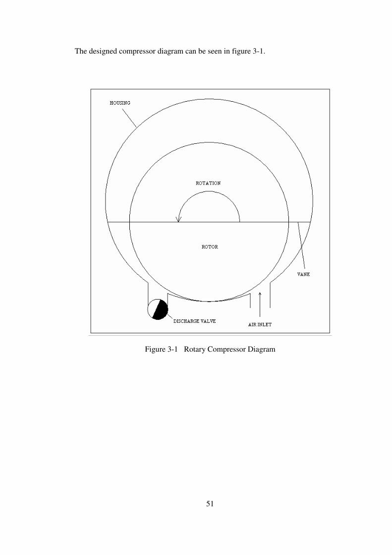
51
The designed compressor diagram can be seen in figure 3-1.
Figure 3-1 Rotary Compressor Diagram
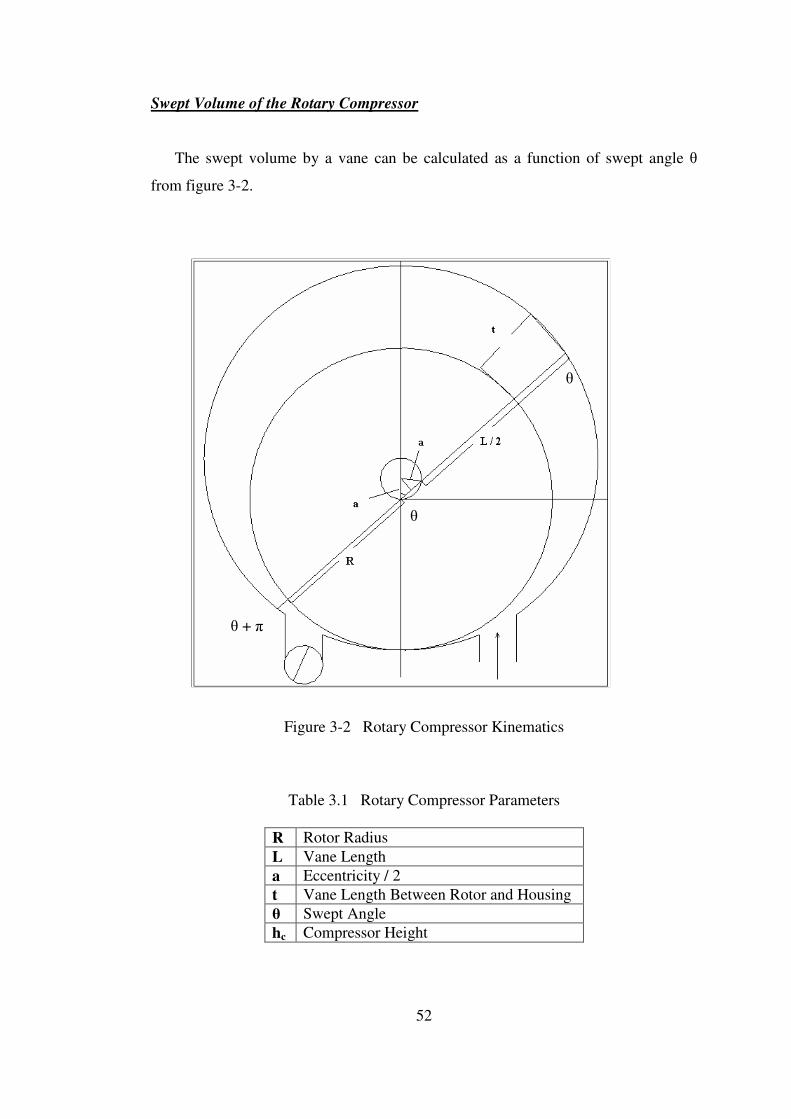
52
Swept Volume of the Rotary Compressor
The swept volume by a vane can be calculated as a function of swept angle θ
from figure 3-2.
θ
θ
θ + π
Figure 3-2 Rotary Compressor Kinematics
Table 3.1 Rotary Compressor Parameters
R Rotor Radius
L Vane Length
a Eccentricity / 2
t Vane Length Between Rotor and Housing
θ Swept Angle
hc Compressor Height

53
Swept Volume (Sw) can be calculated as follows;
cw hdtS ×
= ∫
+πθ
θ
θ. (3.1)
From geometry t can be found as;
))()cos..2(2/( RaLt −−= θ (3.2)
Substituting t into equation 3.1;
( ) ( )[ ] cw hdRaLS ×
−××−= ∫
+πθ
θ
θθcos22/ (3.3)
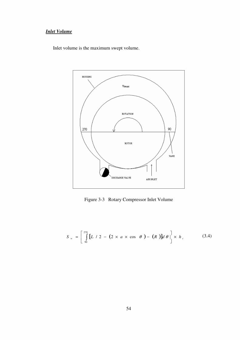
54
Inlet Volume
Inlet volume is the maximum swept volume.
Figure 3-3 Rotary Compressor Inlet Volume
( ) ( )[ ] cw hdRaLS ×
−××−= ∫
270
90
cos22/ θθ (3.4)

55
Design Parameters
Using the thermodynamic design code explained in Chapter 2, the geometry of
the compressor is calculated. The geometric parameters of the rotary compressor are
given below;
R 110 mm
L 140 mm
a 7.5 mm
hc 596 mm
tv 12 mm
Using the geometric data taken from the thermodynamic design code the rotary
compressor was designed in CAD environment.
The rotary compressor is composed of a housing, upper and lower taps, upper
and lower bearing housings, a rotor and its top seals, a vane and its apex seals and
springs, a discharge valve and its bearing housing, two timing pulleys and one timing
belt and two discharge ports.
As the compressor vane divides the compressor housing into two parts, for one
complete revolution, compressor discharges two units of compressed air. The
compressor valve is so designed that it discharges this two units of compressed air to
the discharge ports respectively.
The discharge valve is coupled with the rotary compressor rotor with the help of
two timing pulleys and one timing belt and revolves at the same rpm with the rotor.
The position of the discharge valve relative to the compressor rotor is adjusted with
the timing pulleys by the help of set screws, such that it discharges the compressed
air to both discharge ports at correct times.
An oil pump is used to lubricate the compressor inner surface and the three
bearings. (Two main rotor bearings and one discharge valve bearing)
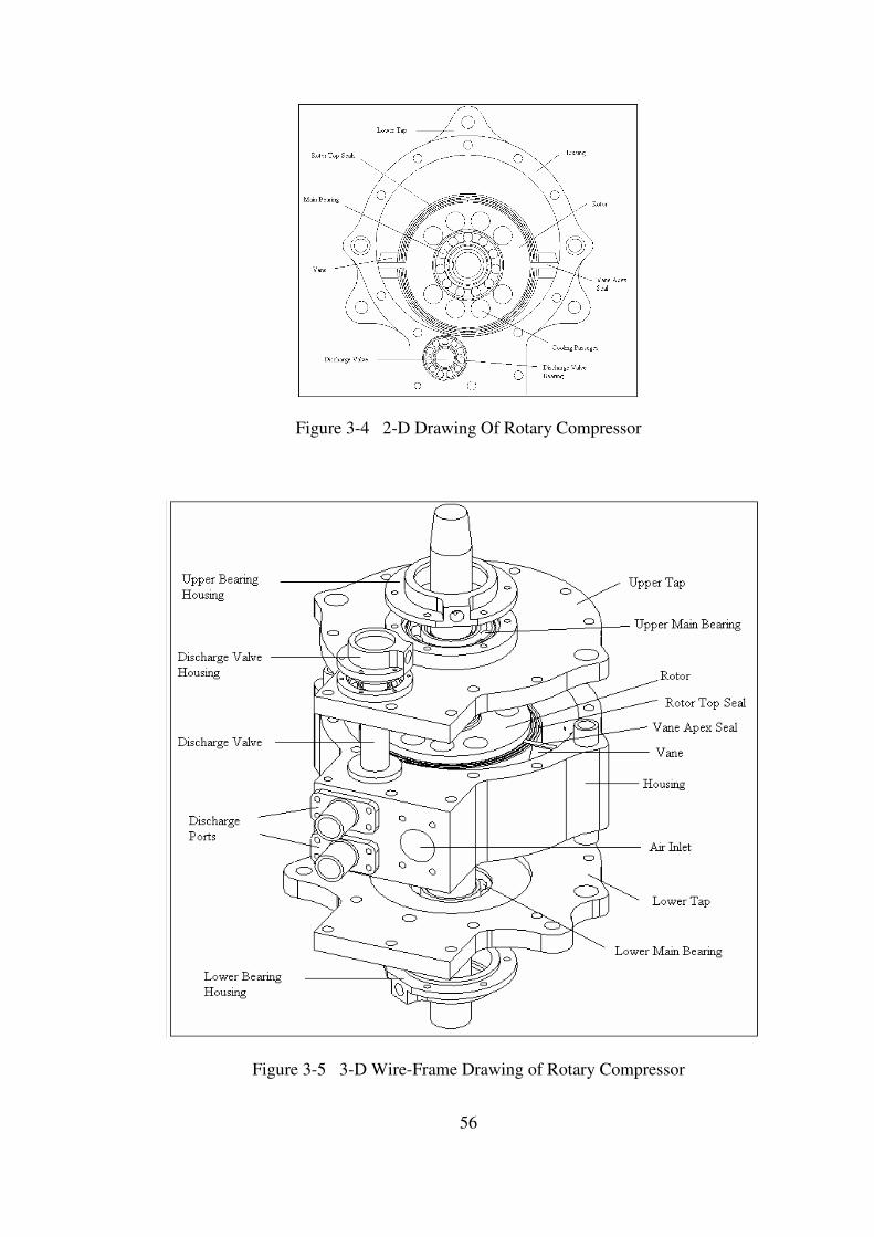
56
Figure 3-4 2-D Drawing Of Rotary Compressor
Figure 3-5 3-D Wire-Frame Drawing of Rotary Compressor
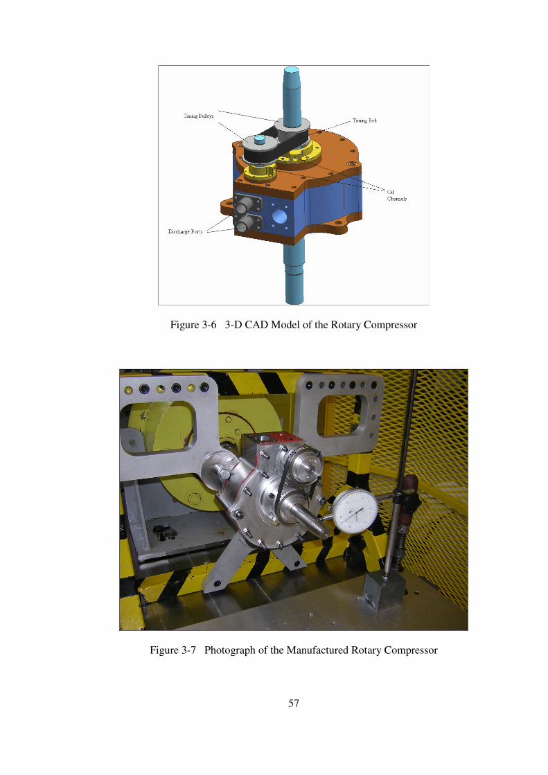
57
Figure 3-6 3-D CAD Model of the Rotary Compressor
Figure 3-7 Photograph of the Manufactured Rotary Compressor

58
3.1.1 Compressor Parts
Compressor Housing
• Compressor housing is the main body of the compressor in which a rotor is
mounted eccentrically.
• Compressor housing is closed by two taps which are positioned by the help of
two bushings and tightened with 13 (Metric 6) bolts and 2 (Metric 10) bolts.
• Inside the housing is machined with a 3-Axis NC Machining Lathe due to its
cycloid shape.
• Two discharge ports are mounted on the housing.
• Discharge valve seal and spring are placed in their channel on the top of the
housing to avoid air leakage.
Figure 3-8 Compressor Housing Model

59
Compressor Upper Tap
• Compressor upper tap has two housings (mean bearing housing and discharge
valve housing)
• The eccentricity of the compressor is defined by the place of the main bearing
housing and the two bushings.
• Main bearing and discharge valve housing taps are mounted on the top of the
upper tap.
• 17 x 35 x 9 ball bearing is tight fitted in the main bearing housing.
• 10 x 17 x 6 ball bearing is tight fitted in the discharge valve housing.
Figure 3-9 Compressor Upper Tap Model

60
Compressor Lower Tap
• Compressor lower tap has one bearing housing.
• The compressor is mounted to the ground with three (Metric 10) bolts from
the three mounting holes on the lower tap.
• Main bearing housing tap is mounted on the top of the upper tap.
• 17 x 35 x 9 ball bearing is tight fitted in the main bearing housing.
• An oil seal is also placed with in the bearing housing tap.
• Main bearing is lubricated from the oil hole on the bearing housing tap.
Figure 3-10 Compressor Lower Tap

61
Compressor Rotor
• Rotor upper and lower seals and springs are placed with in their channels on
both sides of the rotor body.
• Rotor inner seals and springs are placed with in their channel in the vane
channel.
• Rotor is placed in the housing by two main bearings fitted in the housing taps.
• Cooling holes are opened on the top sides of the rotor.
Figure 3-11 Compressor Rotor
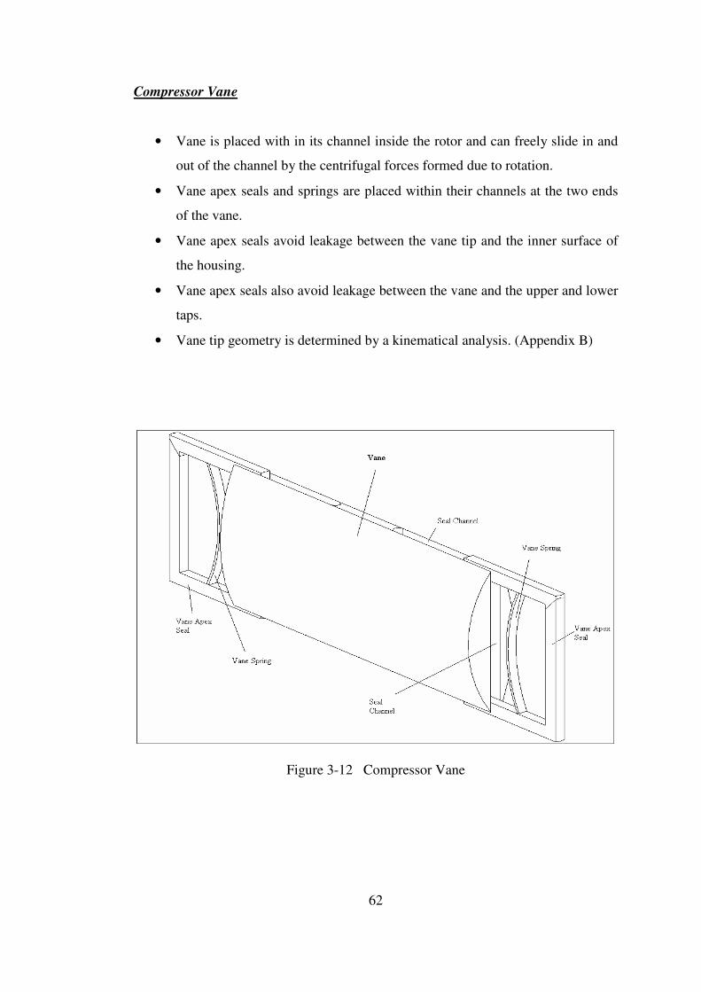
62
Compressor Vane
• Vane is placed with in its channel inside the rotor and can freely slide in and
out of the channel by the centrifugal forces formed due to rotation.
• Vane apex seals and springs are placed within their channels at the two ends
of the vane.
• Vane apex seals avoid leakage between the vane tip and the inner surface of
the housing.
• Vane apex seals also avoid leakage between the vane and the upper and lower
taps.
• Vane tip geometry is determined by a kinematical analysis. (Appendix B)
Figure 3-12 Compressor Vane

63
Compressor Discharge Valve
• Discharge valve is placed with in its housing inside the housing.
• Discharge valve is directly coupled with the rotor by the help of timing
pulleys and timing belt and rotates at the same rpm with the rotor.
• Discharge valve delivers compressed air to the two combustion chambers
from the upper and lower discharge channels opened on it.
• Discharge timing is adjusted by the timing pulleys and timing belt.
Figure 3-13 Compressor Discharge Valve

64
3.1.2 Structural Analysis and Material Selection
Structural analysis of the rotary compressor of the novel engine is done in
ANSYS 9.0 Environment (Finite Element Program). The aim of this work is to
define the manufacturing tolerances and to select the material of the compressor
parts. To do the structural analysis, firstly the critical parts are defined as follows;
For material selection;
• Stress distribution on the housing and the taps of the compressor due to pressure
and temperature exerted by the compressed air onto the inner surfaces.
• Stress distribution on the rotor due to pressure and temperature exerted by the
compressed air, together with the centrifugal force caused by rotation.
• Stress distribution on the vane due to pressure and temperature exerted by the
compressed air, together with the centrifugal force caused by rotation.
• Stress distribution on the discharge valve due to pressure and temperature exerted
by the compressed air, together with the centrifugal force caused by rotation.
For defining the manufacturing tolerance;
• Deformation of the discharge valve and its housing in the compressor housing,
due to thermal and pressure loads.
• Deformation of the vane and its housing in the rotor, due to thermal, pressure and
inertia loads.
• Deformation of the rotor seals and their housings in the rotor, due to thermal,
pressure and inertia loads.
• Deformation of the vane apex seals and their housings in the vane, due to
thermal, pressure and inertia loads.
To make the structural analysis of the rotary compressor, the necessary
temperature and pressure data is taken from the thermodynamic design code where
the temperature and pressure data is given with respect to compressor vane angle θ.
The pressure and temperature data wrt compressor vane angle θ are given in figures
3-14 and 3-15 respectively.

65
Pressure Disribution
0
2
4
6
8
10
12
0 50 100 150 200 250 300 350 400
Vane Angle (degrees)
Pre
ssu
re(A
tm)
Figure 3-14 Pressure Distribution in the Rotary Compressor
Temperature Distribution
0
100
200
300
400
500
600
0 50 100 150 200 250 300 350 400
Vane Angle (Degrees)
Tem
per
atu
e (K
)
Figure 3-15 Temperature Distribution in the Rotary Compressor
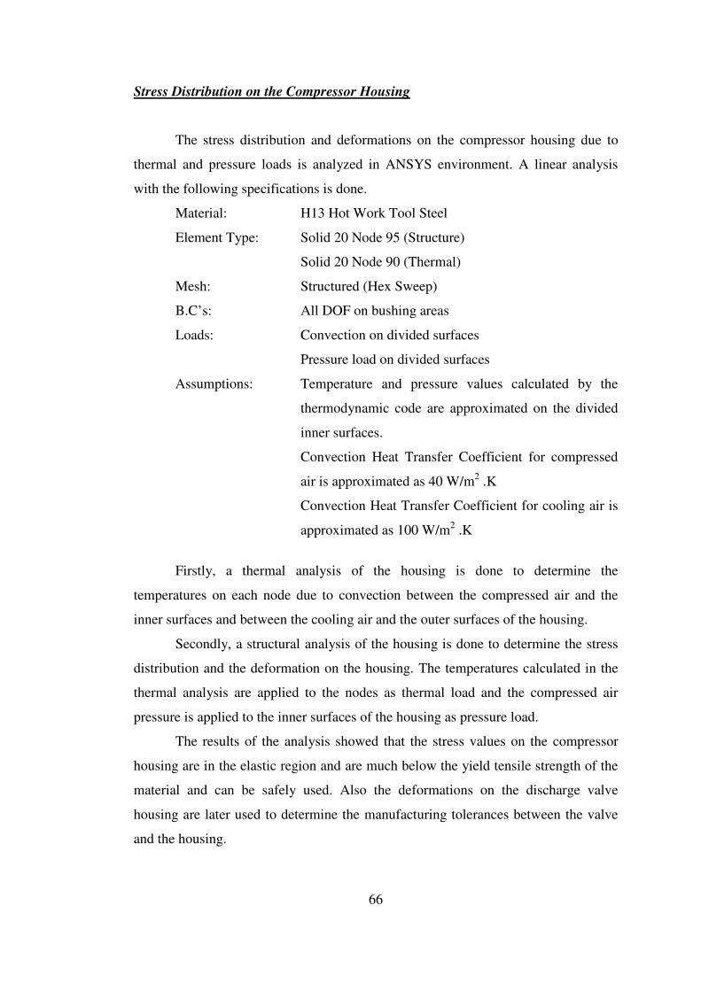
66
Stress Distribution on the Compressor Housing
The stress distribution and deformations on the compressor housing due to
thermal and pressure loads is analyzed in ANSYS environment. A linear analysis
with the following specifications is done.
Material: H13 Hot Work Tool Steel
Element Type: Solid 20 Node 95 (Structure)
Solid 20 Node 90 (Thermal)
Mesh: Structured (Hex Sweep)
B.C’s: All DOF on bushing areas
Loads: Convection on divided surfaces
Pressure load on divided surfaces
Assumptions: Temperature and pressure values calculated by the
thermodynamic code are approximated on the divided
inner surfaces.
Convection Heat Transfer Coefficient for compressed
air is approximated as 40 W/m2 .K
Convection Heat Transfer Coefficient for cooling air is
approximated as 100 W/m2 .K
Firstly, a thermal analysis of the housing is done to determine the
temperatures on each node due to convection between the compressed air and the
inner surfaces and between the cooling air and the outer surfaces of the housing.
Secondly, a structural analysis of the housing is done to determine the stress
distribution and the deformation on the housing. The temperatures calculated in the
thermal analysis are applied to the nodes as thermal load and the compressed air
pressure is applied to the inner surfaces of the housing as pressure load.
The results of the analysis showed that the stress values on the compressor
housing are in the elastic region and are much below the yield tensile strength of the
material and can be safely used. Also the deformations on the discharge valve
housing are later used to determine the manufacturing tolerances between the valve
and the housing.
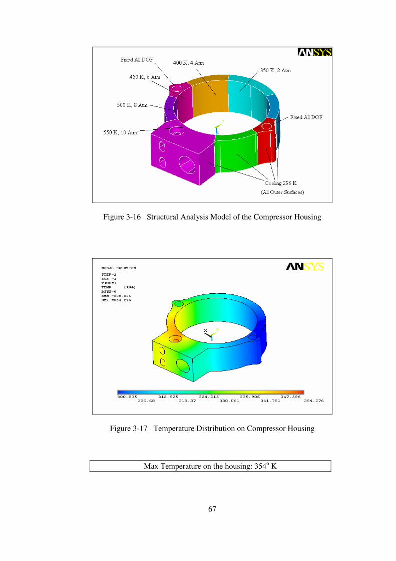
67
Figure 3-16 Structural Analysis Model of the Compressor Housing
Figure 3-17 Temperature Distribution on Compressor Housing
Max Temperature on the housing: 354o K
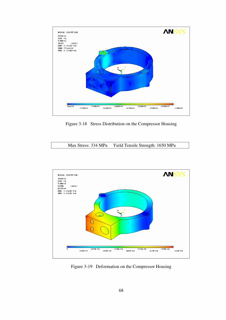
68
Figure 3-18 Stress Distribution on the Compressor Housing
Max Stress: 334 MPa Yield Tensile Strength: 1650 MPa
Figure 3-19 Deformation on the Compressor Housing
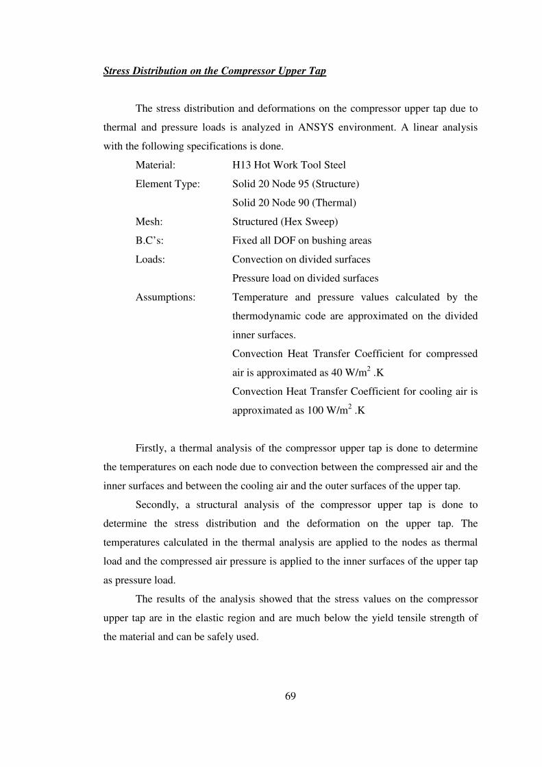
69
Stress Distribution on the Compressor Upper Tap
The stress distribution and deformations on the compressor upper tap due to
thermal and pressure loads is analyzed in ANSYS environment. A linear analysis
with the following specifications is done.
Material: H13 Hot Work Tool Steel
Element Type: Solid 20 Node 95 (Structure)
Solid 20 Node 90 (Thermal)
Mesh: Structured (Hex Sweep)
B.C’s: Fixed all DOF on bushing areas
Loads: Convection on divided surfaces
Pressure load on divided surfaces
Assumptions: Temperature and pressure values calculated by the
thermodynamic code are approximated on the divided
inner surfaces.
Convection Heat Transfer Coefficient for compressed
air is approximated as 40 W/m2 .K
Convection Heat Transfer Coefficient for cooling air is
approximated as 100 W/m2 .K
Firstly, a thermal analysis of the compressor upper tap is done to determine
the temperatures on each node due to convection between the compressed air and the
inner surfaces and between the cooling air and the outer surfaces of the upper tap.
Secondly, a structural analysis of the compressor upper tap is done to
determine the stress distribution and the deformation on the upper tap. The
temperatures calculated in the thermal analysis are applied to the nodes as thermal
load and the compressed air pressure is applied to the inner surfaces of the upper tap
as pressure load.
The results of the analysis showed that the stress values on the compressor
upper tap are in the elastic region and are much below the yield tensile strength of
the material and can be safely used.
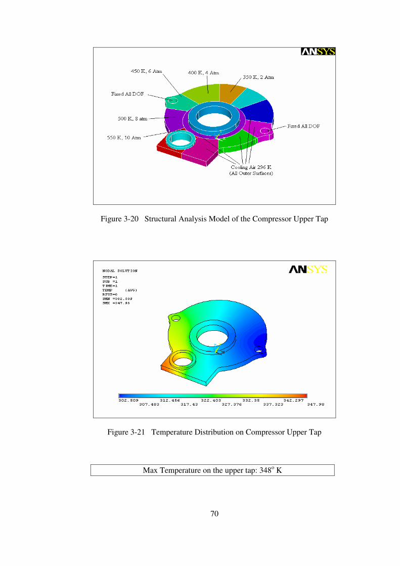
70
Figure 3-20 Structural Analysis Model of the Compressor Upper Tap
Figure 3-21 Temperature Distribution on Compressor Upper Tap
Max Temperature on the upper tap: 348o K
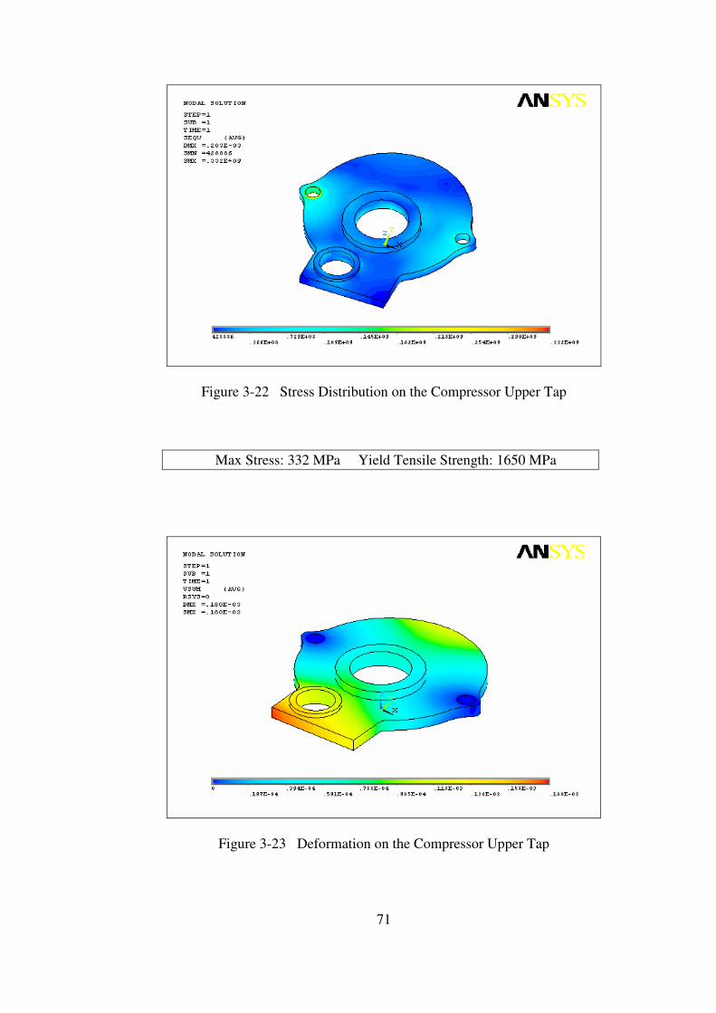
71
Figure 3-22 Stress Distribution on the Compressor Upper Tap
Max Stress: 332 MPa Yield Tensile Strength: 1650 MPa
Figure 3-23 Deformation on the Compressor Upper Tap

72
Stress Distribution on the Compressor Lower Tap
The stress distribution and deformations on the compressor lower tap due to
thermal and pressure loads is analyzed in ANSYS environment. A linear analysis
with the following specifications is done.
Material: H13 Hot Work Tool Steel
Element Type: Solid 20 Node 95 (Structure)
Solid 20 Node 90 (Thermal)
Mesh: Structured (Hex Sweep)
B.C’s: Fixed all DOF on mounting holes
Loads: Convection on divided surfaces
Pressure load on divided surfaces
Assumptions: Temperature and pressure values calculated by the
thermodynamic code are approximated on the divided
inner surfaces.
Convection Heat Transfer Coefficient for compressed
air is approximated as 40 W/m2 .K
Convection Heat Transfer Coefficient for cooling air is
approximated as 100 W/m2 .K
Firstly, a thermal analysis of the compressor lower tap is done to determine
the temperatures on each node due to convection between the compressed air and the
inner surfaces and between the cooling air and the outer surfaces of the lower tap.
Secondly, a structural analysis of the compressor lower tap is done to
determine the stress distribution and the deformation on the lower tap. The
temperatures calculated in the thermal analysis are applied to the nodes as thermal
load and the compressed air pressure is applied to the inner surfaces of the lower tap
as pressure load.
The results of the analysis showed that the stress values on the compressor
lower tap are in the elastic region and are much below the yield tensile strength of
the material and can be safely used.
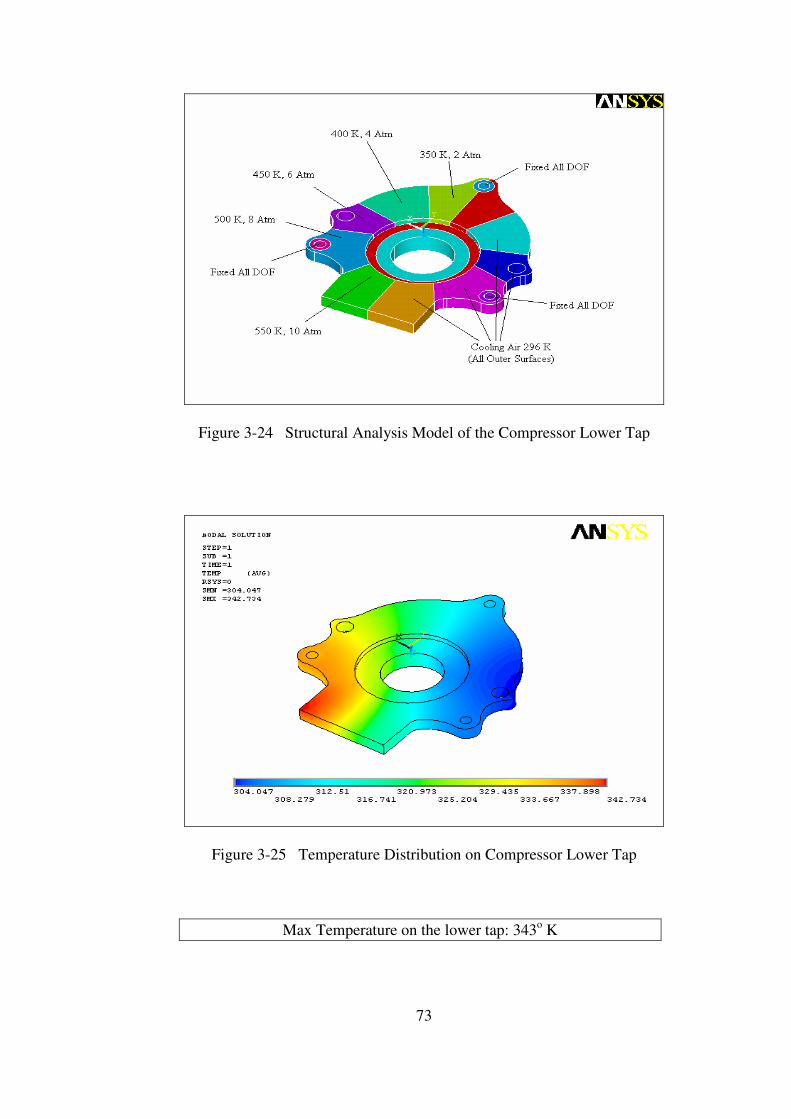
73
Figure 3-24 Structural Analysis Model of the Compressor Lower Tap
Figure 3-25 Temperature Distribution on Compressor Lower Tap
Max Temperature on the lower tap: 343o K
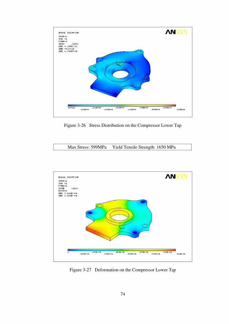
74
Figure 3-26 Stress Distribution on the Compressor Lower Tap
Max Stress: 599MPa Yield Tensile Strength: 1650 MPa
Figure 3-27 Deformation on the Compressor Lower Tap
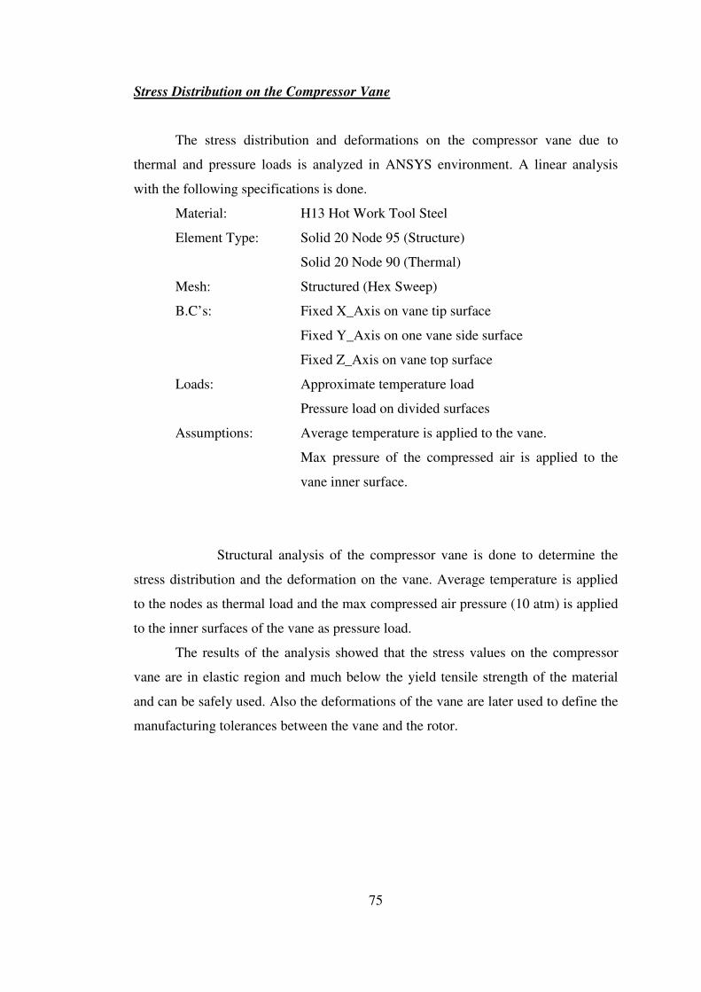
75
Stress Distribution on the Compressor Vane
The stress distribution and deformations on the compressor vane due to
thermal and pressure loads is analyzed in ANSYS environment. A linear analysis
with the following specifications is done.
Material: H13 Hot Work Tool Steel
Element Type: Solid 20 Node 95 (Structure)
Solid 20 Node 90 (Thermal)
Mesh: Structured (Hex Sweep)
B.C’s: Fixed X_Axis on vane tip surface
Fixed Y_Axis on one vane side surface
Fixed Z_Axis on vane top surface
Loads: Approximate temperature load
Pressure load on divided surfaces
Assumptions: Average temperature is applied to the vane.
Max pressure of the compressed air is applied to the
vane inner surface.
Structural analysis of the compressor vane is done to determine the
stress distribution and the deformation on the vane. Average temperature is applied
to the nodes as thermal load and the max compressed air pressure (10 atm) is applied
to the inner surfaces of the vane as pressure load.
The results of the analysis showed that the stress values on the compressor
vane are in elastic region and much below the yield tensile strength of the material
and can be safely used. Also the deformations of the vane are later used to define the
manufacturing tolerances between the vane and the rotor.
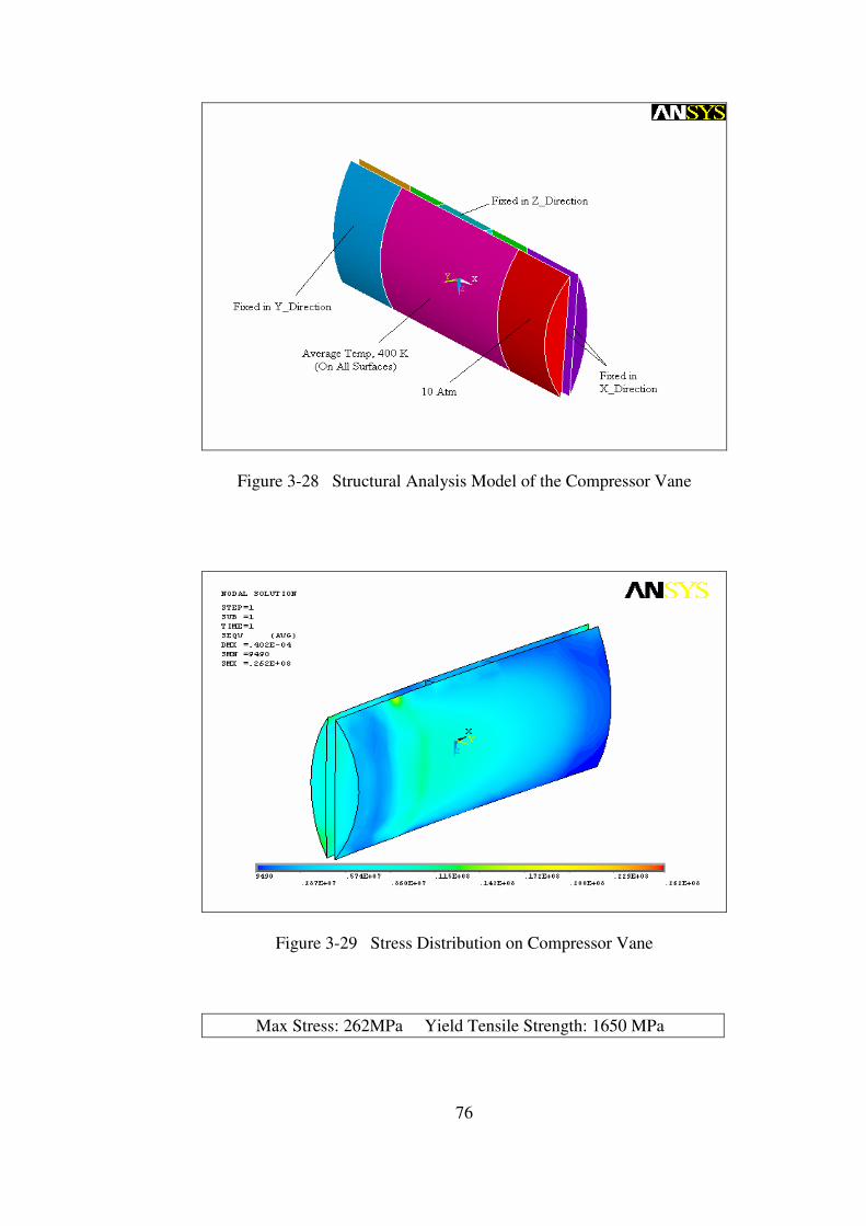
76
Figure 3-28 Structural Analysis Model of the Compressor Vane
Figure 3-29 Stress Distribution on Compressor Vane
Max Stress: 262MPa Yield Tensile Strength: 1650 MPa

77
Figure 3-30 Deformation on the Compressor Vane
78
Stress Distribution on the Compressor Rotor
The stress distribution and deformations on the compressor rotor due to
thermal and pressure and inertia loads is analyzed in ANSYS environment. A linear
analysis with the following specifications is done.
Material: H13 Hot Work Tool Steel
Element Type: Tet 10 Node 92 (Structure)
Tet 10 Node 87 (Thermal)
Mesh: Unstructured (Tet)
B.C’s: Fixed in radial and Z_Axis on bearing surfaces
Loads: Convection on divided surfaces
Max. Pressure load on divided surfaces
Angular Velocity of 6000 rpm
Assumptions: Convection Heat Transfer Coefficient for compressed
air is approximated as 40 W/m2 .K
Convection Heat Transfer Coefficient for cooling air is
approximated as 100 W/m2 .K
Convection Heat Transfer Coefficient for cooling oil is
approximated as 150 W/m2 .K
Firstly, a thermal analysis of the compressor rotor is done to determine the
temperatures on each node due to convection between the compressed air and the
inner surfaces and between the cooling air and oil and the outer surfaces of the rotor.
Secondly, a structural analysis of the compressor rotor is done to determine
the stress distribution and the deformation on the rotor. The temperatures calculated
in the thermal analysis are applied to the nodes as thermal load and the max
compressed air pressure is applied to the inner surfaces of the rotor as pressure load.
Also angular velocity of 6000 rpm is applied.
The results of the analysis showed that the stress values on the compressor
rotor are in the elastic region and are much below the yield tensile strength of the
material and can be safely used. Also the deformations on the vane housing are later
used to determine the manufacturing tolerances between the rotor and the vane.
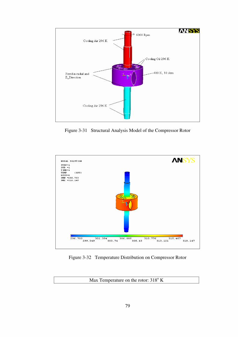
79
Figure 3-31 Structural Analysis Model of the Compressor Rotor
Figure 3-32 Temperature Distribution on Compressor Rotor
Max Temperature on the rotor: 318o K

80
Figure 3-33 Stress Distribution on the Compressor Rotor
Max Stress: 259 MPa Yield Tensile Strength: 1650 MPa
Figure 3-34 Deformation on the Compressor Rotor
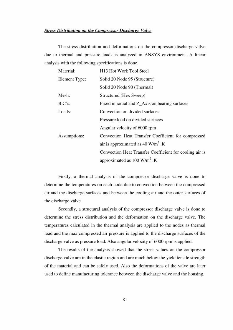
81
Stress Distribution on the Compressor Discharge Valve
The stress distribution and deformations on the compressor discharge valve
due to thermal and pressure loads is analyzed in ANSYS environment. A linear
analysis with the following specifications is done.
Material: H13 Hot Work Tool Steel
Element Type: Solid 20 Node 95 (Structure)
Solid 20 Node 90 (Thermal)
Mesh: Structured (Hex Sweep)
B.C’s: Fixed in radial and Z_Axis on bearing surfaces
Loads: Convection on divided surfaces
Pressure load on divided surfaces
Angular velocity of 6000 rpm
Assumptions: Convection Heat Transfer Coefficient for compressed
air is approximated as 40 W/m2 .K
Convection Heat Transfer Coefficient for cooling air is
approximated as 100 W/m2 .K
Firstly, a thermal analysis of the compressor discharge valve is done to
determine the temperatures on each node due to convection between the compressed
air and the discharge surfaces and between the cooling air and the outer surfaces of
the discharge valve.
Secondly, a structural analysis of the compressor discharge valve is done to
determine the stress distribution and the deformation on the discharge valve. The
temperatures calculated in the thermal analysis are applied to the nodes as thermal
load and the max compressed air pressure is applied to the discharge surfaces of the
discharge valve as pressure load. Also angular velocity of 6000 rpm is applied.
The results of the analysis showed that the stress values on the compressor
discharge valve are in the elastic region and are much below the yield tensile strength
of the material and can be safely used. Also the deformations of the valve are later
used to define manufacturing tolerance between the discharge valve and the housing.

82
Figure 3-35 Structural Analysis Model of the Compressor Discharge Valve
Figure 3-36 Temperature Distribution on Compressor Discharge Valve
Max Temperature on the discharge valve: 348o K

83
Figure 3-37 Stress Distribution on the Compressor Discharge Valve
Max Stress: 163MPa Yield Tensile Strength: 1650 MPa
Figure 3-38 Deformation on the Compressor Discharge Valve

84
Stress Distribution on the Compressor Vane Apex Seal
The stress distribution and deformations on the compressor vane apex seal
due to thermal loads is analyzed in ANSYS environment. A linear analysis with the
following specifications is done.
Material: H13 Hot Work Tool Steel
Element Type: Solid 20 Node 95 (Structure)
Solid 20 Node 90 (Thermal)
Mesh: Structured (Hex Sweep)
B.C’s: Fixed X_Axis on vane apex seal tip surface
Fixed Y_Axis on vane apex seal top surface
Fixed Z_Axis on one vane apex seal side surface
Loads: Approximate temperature load
Assumptions: Average temperature is applied to the vane apex seal.
Structural analysis of the compressor vane apex seal is done to
determine the stress distribution and the deformation on the vane apex seal. Average
temperature (400 K) is applied to the nodes as thermal load.
The results of the analysis showed that the stress values on the compressor
vane apex seal are in elastic region and much below the yield tensile strength of the
material and can be safely used. Also the deformations of the vane apex seal are later
used to define the manufacturing tolerances between the vane and vane apex seal.
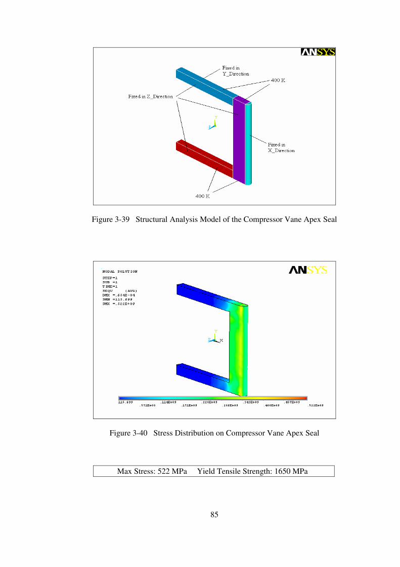
85
Figure 3-39 Structural Analysis Model of the Compressor Vane Apex Seal
Figure 3-40 Stress Distribution on Compressor Vane Apex Seal
Max Stress: 522 MPa Yield Tensile Strength: 1650 MPa
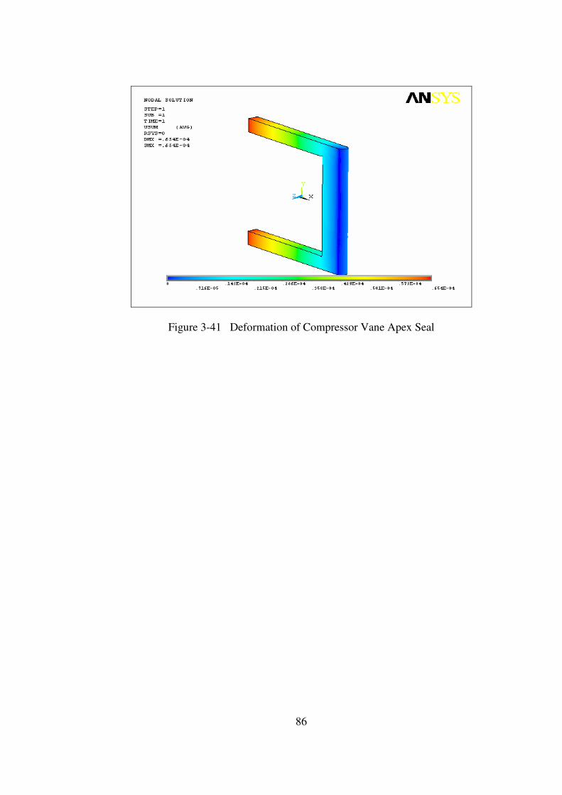
86
Figure 3-41 Deformation of Compressor Vane Apex Seal
87
Stress Distribution on the Compressor Rotor Top Seal
The stress distribution and deformations on the compressor rotor top seal due
to thermal loads is analyzed in ANSYS environment. A linear analysis with the
following specifications is done.
Material: Gray Cast Iron
Element Type: Solid 20 Node 95 (Structure)
Solid 20 Node 90 (Thermal)
Mesh: Structured (Hex Sweep)
B.C’s: Fixed X_Axis on rotor top seal tip surface
Fixed Y_Axis on rotor top seal tip surface
Fixed Z_Axis on one rotor top seal top surface
Loads: Approximate temperature load
Assumptions: Average temperature is applied to the rotor top seal.
Structural analysis of the compressor rotor top seal is done to
determine the stress distribution and the deformation on the rotor top seal. Average
temperature (400 K) is applied to the nodes as thermal load.
The results of the analysis showed that the stress values on the compressor
rotor top seal are in elastic region and much below the yield tensile strength of the
material and can be safely used. Also the deformations of the rotor top seal are later
used to define the manufacturing tolerances between the rotor and rotor top seal.
88
Figure 3-42 Structural Analysis Model of the Compressor Rotor Top Seal
Figure 3-43 Stress Distribution on Compressor Rotor Top Seal
Max Stress: 987 MPa Yield Tensile Strength: 1650 MPa
89
Figure 3-44 Deformation of Compressor Rotor Top Seal

90
Manufacturing Tolerance between Discharge Valve and Housing
Due to thermal and pressure loads on the discharge valve and housing
surfaces, deformations on the materials occur. These deformations are examined to
determine the manufacturing tolerances of both parts so that the discharge valve can
revolve within its housing without stacking while still assuring good sealing
capacity.
By examining the compressor discharge valve deformation, it is seen that the
discharge valve deforms 0.0308 mm max radially.
By examining the compressor housing, it is seen that the discharge valve
housing deforms 0.0409 mm max radially.
As a result, 0.08 mm gap tolerance between the discharge valve and the
housing will assure discharge valve to revolve within the housing without stacking.
This gap tolerance can be guaranteed by manufacturing the discharge valve 0.04 mm
smaller in diameter and by opening the valve housing hole 0.04 mm larger in
diameter.
Manufacturing Tolerance between Vane and Rotor
Due to thermal and pressure and inertia loads on the vane and rotor surfaces,
deformations on the materials occur. These deformations are examined to determine
the manufacturing tolerances of both parts so that the vane can move within the rotor
without stacking while still assuring good sealing characteristics.
By examining the compressor vane deformation, it is seen that the vane
deforms 0.04 mm max.
By examining the compressor rotor, it is seen that the vane channel deforms
0.3 mm max.
As a result, 0.35 mm gap tolerance between the vane and the rotor will assure
compressor vane to revolve within the rotor without stacking. This gap tolerance can
be guaranteed by manufacturing the compressor vane 0.05 mm smaller in thickness
and by opening the vane channel 0.3 mm larger in thickness.
91
Manufacturing Tolerance between Vane Apex Seal and Vane
Due to thermal and pressure loads on the vane and vane apex seal surfaces,
deformations on the materials occur. These deformations are examined to determine
the manufacturing tolerances of both parts so that the vane apex seal can move
within the vane without stacking, while still assuring good sealing characteristics.
By examining the compressor vane apex seal deformation, it is seen that the
seal deforms 0.06 mm max in thickness.
By examining the compressor vane, it is seen that the apex seal channel
deforms 0.04 mm max in thickness.
As a result, 0.1 mm gap tolerance between the vane apex seal and the vane
will assure apex seal to move within the channel without stacking. This gap tolerance
can be guaranteed by manufacturing the vane apex seal 0.06 mm smaller in thickness
and by opening the vane seal channel 0.04 mm larger in thickness.
Manufacturing Tolerance between Rotor Top Seal and Rotor
Due to thermal and pressure loads on the rotor and rotor top seal surfaces,
deformations on the materials occur. These deformations are examined to determine
the manufacturing tolerances of both parts so that the rotor top seal can move within
the rotor seal channel without stacking, while still assuring good sealing
characteristics.
By examining the compressor rotor top seal deformation, it is seen that the
seal deforms 0.3 mm max in diameter.
By examining the compressor rotor, it is seen that the rotor top seal channel
deforms 0.05 mm max in thickness.
As a result, 0.35 mm gap tolerance between the rotor top seal and the rotor
seal channel will assure top seal to move within the channel without stacking. This
gap tolerance can be guaranteed by manufacturing the rotor top seal 0.3 mm smaller
in thickness and by opening the rotor top seal channel 0.05 mm larger in diameter.
92
Compressor Material
With respect to the structural analysis results, H13 Hot Work Tool Steel is
selected as the material of the rotary compressor prototype that will be manufactured.
The selection criteria of the material are given below;
• Excellent wear resistance and hot toughness.
• High thermal shock resistance.
• Good thermal conductivity and tolerate some water cooling in service.
• High temperature tensile strength.
• Good machinability.
Regarding these properties of the material, it is one of the best alternatives that
can be used for the manufacturing of the rotary compressor prototype. Beside these
properties, the structural analysis of the compressor parts is done using this material
and the analysis results showed that the selected material is suitable for the
prototype. Therefore the material of the rotary compressor housing, taps, bearing
housings, rotor, vane, valve, valve housing is selected to be H13 Hot Work Tool
Steel. (Properties of H13 Hot Work Tool Steel is given in Appendix D)
Compressor Vane Apex Seal Material
Two alternatives for the vane apex seal have been considered.
First alternative for the rotary compressor vane apex seal is H13 hot work tool
steel because of its good mechanical and thermal properties.
However, as the material of the compressor housing is also H13, there would
be great wear deformation on both surfaces of the housing and seal due to friction.
By arranging the hardness of both parts (housing being harder) could decrease the
wear but still it would be over the desired limits of deformation. (Properties of H13
Hot Work Tool Steel is given in Appendix D)
93
The second alternative for the rotary compressor vane apex seal is the fiber
material which is mostly used for the vanes of the rotary vane compressors in the
market. As the temperatures in the rotary compressor are quite low, fiber could
display enough mechanical properties while decreasing wear deformation on the
housing surface to nearly zero.
Compressor Rotor Top Seals
The best alternative for the rotary compressor rotor top seal is the gray cast iron
which is also used in the piston engines’ piston head seals. Also seal is plated with
chromium to give excellent wear and scuff resistance under very marginal lubrication
conditions. Because of its good wear properties, the deformation on the tap inner
surfaces, where the rotor top seals are in contact with, will be minimum while good
sealing will be achieved. (Properties of Gray Cast Iron is given in Appendix D)
Compressor Vane Apex and Rotor Top Seal Springs
Two alternatives for the springs have been considered.
The first alternative for the rotary compressor springs is a cobalt based super-
alloy called Elgiloy Co-Cr-Ni Alloy. It has high strength, fatigue life and good
mechanical properties. This material is also used in other rotary engine applications
in the market as seal springs. (Properties of Elgiloy is given in Appendix D)
The second alternative for the rotary compressor springs is a nickel based
super-alloy called Inconel 718. It has high strength, ductility, fatigue life and good
mechanical properties. Its excellent relaxation resistance is useful for high-
temperature springs and bolts. The alloy has good resistance to corrosion and
oxidation along with high tensile and creep-rupture properties at temperatures to
about 1300°F (700°C). (Properties of Inconel 718 is given in Appendix D)
94
3.2 Turbine Design
• The designed turbine of the novel turbo rotary engine is a sliding vane turbine
which is a positive displacement type rotary turbine. This turbine uses a rotor
equipped with a radially movable single sliding vane, mounted eccentrically in a
crescent shape cavity. The single vane is free to slide in and out of the slot cut
into the rotor. As the rotor rotates, both ends of the sliding vane are extending
radially outward and are in contact with the cycloid inner surface of the housing
peripheral at all rotational angles by the centrifugal force. Apex seals at the tips
of the vane are used to achieve proper sealing. Combustion gases enter through
the two inlet ports. As the combustion gases entering the turbine hit the vane and
turn the eccentrically mounted rotor. As the space between the rotor, vane and the
housing increases, combustion gases expand, until the vane reaches to the
exhaust.
• Also cooling oil is sprayed into the housing to absorb heat; keeping air
temperature relatively low, improving sealing and lubricating the vane tips before
it is burned.
• The designed sliding vane turbine needs a valve at the inlet port to take the
combustion gases from the two combustion chambers at the right time. The valve
must open one port to expand the combustion gases while keeping the other port
closed, enabling the compressor to compress the air to the desired pressure. After
exhaust is completed it will close the port and wait for the next combustion to
occur before opening the other port.
The designed turbine diagram can be seen in figure 3-45.

95
Figure 3-45 Rotary Turbine Diagram
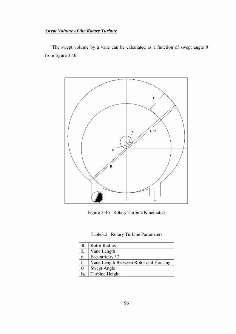
96
Swept Volume of the Rotary Turbine
The swept volume by a vane can be calculated as a function of swept angle θ
from figure 3.46.
Figure 3-46 Rotary Turbine Kinematics
Table3.2 Rotary Turbine Parameters
R Rotor Radius
L Vane Length
a Eccentricity / 2
t Vane Length Between Rotor and Housing
θ Swept Angle
ht Turbine Height
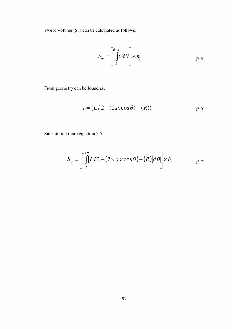
97
Swept Volume (Sw) can be calculated as follows;
tw hdtS ×
= ∫
+πθ
θ
θ. (3.5)
From geometry can be found as;
))()cos..2(2/( RaLt −−= θ (3.6)
Substituting t into equation 3.5;
( ) ( )[ ] tw hdRaLS ×
−××−= ∫
+πθ
θ
θθcos22/ (3.7)

98
Expansion Volume
Expansion volume is the maximum swept volume.
90o 270
o
Figure 3-47 Turbine Expansion Volume
( ) ( )[ ] tw hdRaLS ×
−××−= ∫
270
90
cos22/ θθ (3-8)
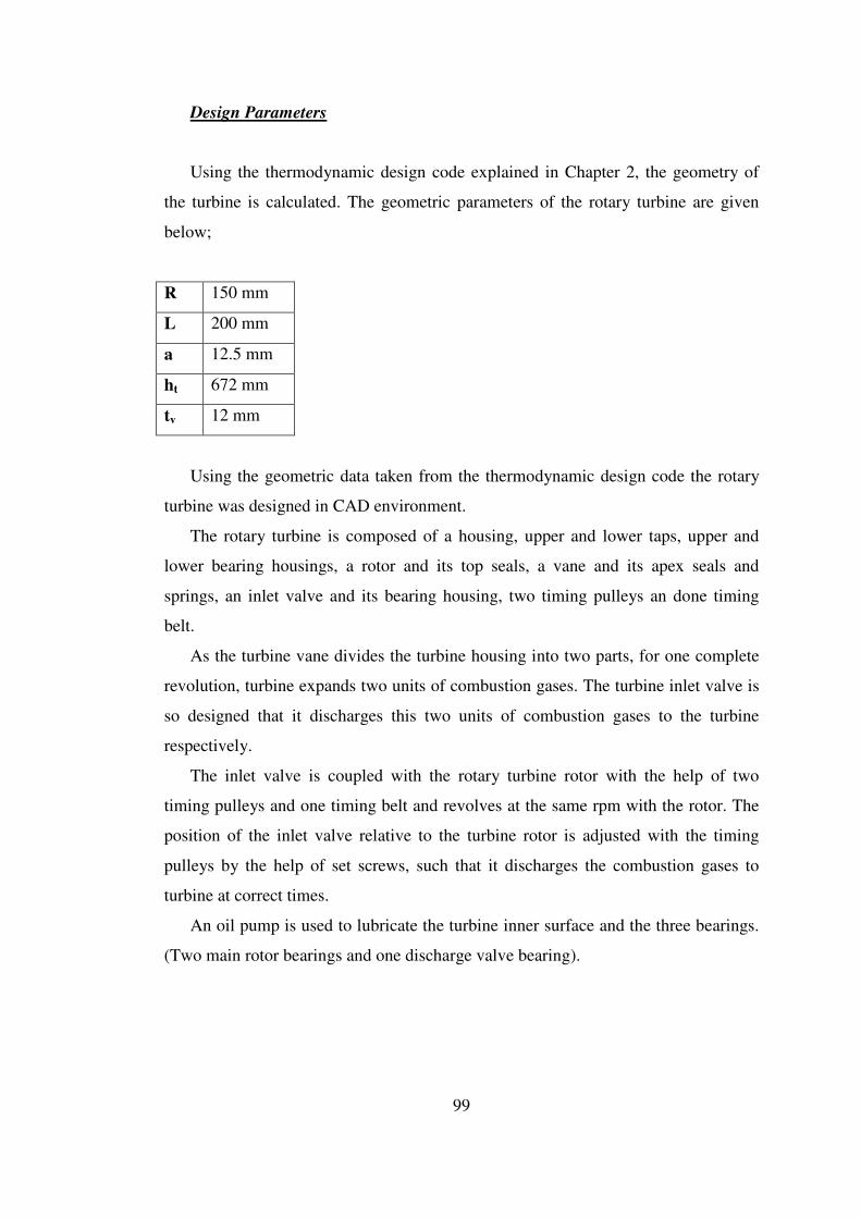
99
Design Parameters
Using the thermodynamic design code explained in Chapter 2, the geometry of
the turbine is calculated. The geometric parameters of the rotary turbine are given
below;
R 150 mm
L 200 mm
a 12.5 mm
ht 672 mm
tv 12 mm
Using the geometric data taken from the thermodynamic design code the rotary
turbine was designed in CAD environment.
The rotary turbine is composed of a housing, upper and lower taps, upper and
lower bearing housings, a rotor and its top seals, a vane and its apex seals and
springs, an inlet valve and its bearing housing, two timing pulleys an done timing
belt.
As the turbine vane divides the turbine housing into two parts, for one complete
revolution, turbine expands two units of combustion gases. The turbine inlet valve is
so designed that it discharges this two units of combustion gases to the turbine
respectively.
The inlet valve is coupled with the rotary turbine rotor with the help of two
timing pulleys and one timing belt and revolves at the same rpm with the rotor. The
position of the inlet valve relative to the turbine rotor is adjusted with the timing
pulleys by the help of set screws, such that it discharges the combustion gases to
turbine at correct times.
An oil pump is used to lubricate the turbine inner surface and the three bearings.
(Two main rotor bearings and one discharge valve bearing).

100
Figure 3-48 2-D Drawing of Rotary Turbine
Figure 3-49 3-D Wire-Frame Drawing of Rotary Turbine
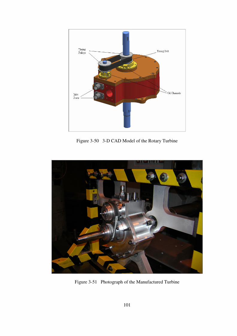
101
Figure 3-50 3-D CAD Model of the Rotary Turbine
Figure 3-51 Photograph of the Manufactured Turbine
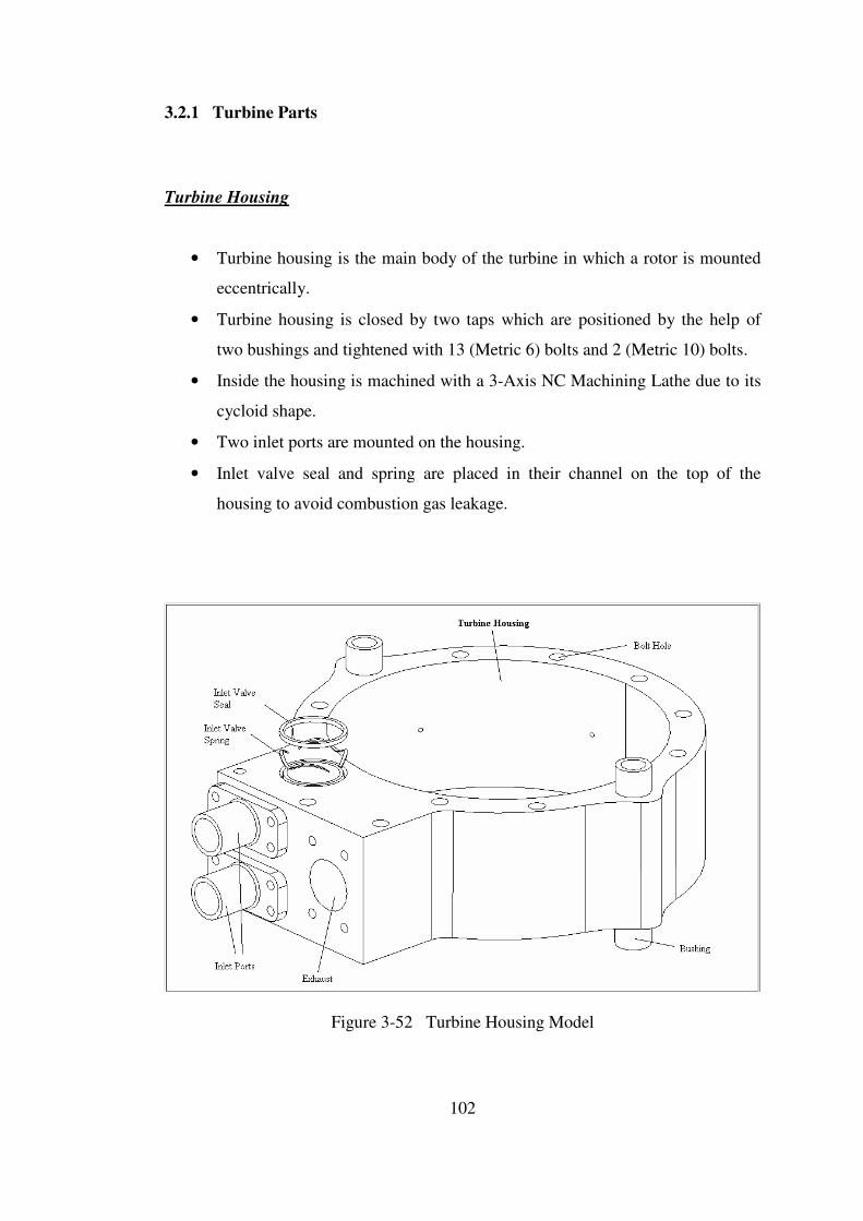
102
3.2.1 Turbine Parts
Turbine Housing
• Turbine housing is the main body of the turbine in which a rotor is mounted
eccentrically.
• Turbine housing is closed by two taps which are positioned by the help of
two bushings and tightened with 13 (Metric 6) bolts and 2 (Metric 10) bolts.
• Inside the housing is machined with a 3-Axis NC Machining Lathe due to its
cycloid shape.
• Two inlet ports are mounted on the housing.
• Inlet valve seal and spring are placed in their channel on the top of the
housing to avoid combustion gas leakage.
Figure 3-52 Turbine Housing Model
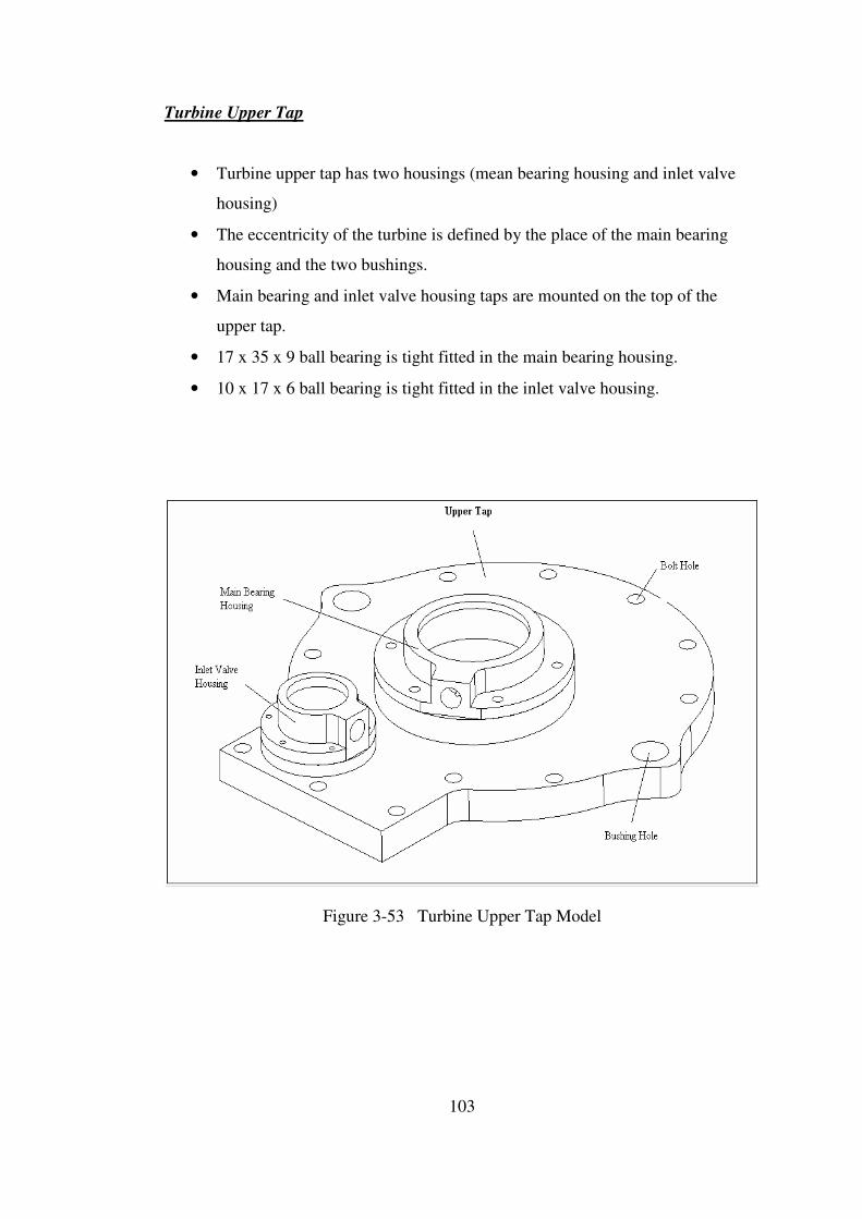
103
Turbine Upper Tap
• Turbine upper tap has two housings (mean bearing housing and inlet valve
housing)
• The eccentricity of the turbine is defined by the place of the main bearing
housing and the two bushings.
• Main bearing and inlet valve housing taps are mounted on the top of the
upper tap.
• 17 x 35 x 9 ball bearing is tight fitted in the main bearing housing.
• 10 x 17 x 6 ball bearing is tight fitted in the inlet valve housing.
Figure 3-53 Turbine Upper Tap Model

104
Turbine Lower Tap
• Turbine lower tap has one bearing housing.
• The turbine is mounted to the ground with three (Metric 10) bolts from the
three mounting holes on the lower tap.
• Main bearing housing tap is mounted on the top of the upper tap.
• 17 x 35 x 9 ball bearing is tight fitted in the main bearing housing.
• An oil seal is also placed with in the bearing housing tap.
• Main bearing is lubricated from the oil hole on the bearing housing tap.
Figure 3-54 Turbine Lower Tap

105
Turbine Rotor
• Rotor upper and lower seals and springs are placed with in their channels on
both sides of the rotor body.
• Rotor inner seals and springs are placed with in their channel in the vane
channel.
• Rotor is placed in the housing by two main bearings fitted in the housing taps.
• Cooling holes are opened on the top sides of the rotor.
Figure 3-55 Turbine Rotor
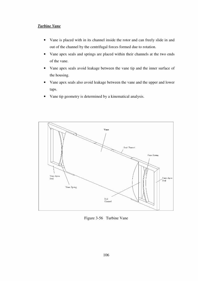
106
Turbine Vane
• Vane is placed with in its channel inside the rotor and can freely slide in and
out of the channel by the centrifugal forces formed due to rotation.
• Vane apex seals and springs are placed within their channels at the two ends
of the vane.
• Vane apex seals avoid leakage between the vane tip and the inner surface of
the housing.
• Vane apex seals also avoid leakage between the vane and the upper and lower
taps.
• Vane tip geometry is determined by a kinematical analysis.
Figure 3-56 Turbine Vane
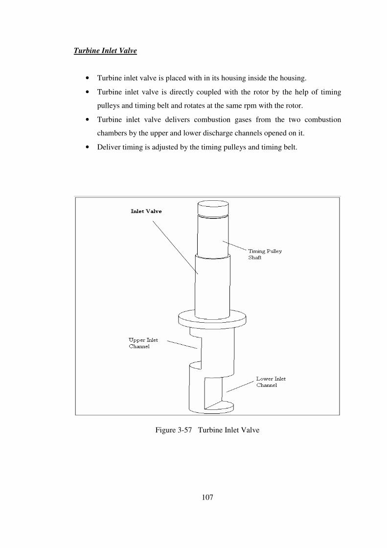
107
Turbine Inlet Valve
• Turbine inlet valve is placed with in its housing inside the housing.
• Turbine inlet valve is directly coupled with the rotor by the help of timing
pulleys and timing belt and rotates at the same rpm with the rotor.
• Turbine inlet valve delivers combustion gases from the two combustion
chambers by the upper and lower discharge channels opened on it.
• Deliver timing is adjusted by the timing pulleys and timing belt.
Figure 3-57 Turbine Inlet Valve
108
3.2.2 Structural Analysis and Material Selection
Structural analysis of the rotary turbine of the novel engine is done in ANSYS
9.0 Environment (Finite Element Program). The aim of this work is to define the
manufacturing tolerances and to select the material of the turbine parts. To do the
structural analysis, firstly the critical parts are defined as follows;
For material selection;
• Stress distribution on the housing and the taps of the turbine due to pressure and
temperature exerted by the combustion gases onto the inner surfaces.
• Stress distribution on the rotor due to pressure and temperature exerted by the
combustion gases, together with the centrifugal force caused by rotation.
• Stress distribution on the vane due to pressure and temperature exerted by the
combustion gases, together with the centrifugal force caused by rotation.
• Stress distribution on the inlet valve due to pressure and temperature exerted by
the combustion gases, together with the centrifugal force caused by rotation.
For defining the manufacturing tolerance;
• Deformation of the inlet valve and its housing in the turbine housing, due to
thermal and pressure loads.
• Deformation of the vane and its housing in the rotor, due to thermal and pressure
loads.
• Deformation of the rotor top seals and their housings in the rotor, due to thermal
and pressure loads.
• Deformation of the vane apex seals and their housings in the vane, due to thermal
and pressure loads.
To make the structural analysis of the rotary turbine, the necessary temperature
and pressure data is taken from the thermodynamic design code where the
temperature and pressure data is given with respect to turbine vane angle θ. The
pressure and temperature data wrt turbine vane angle θ are given in figures 3-58 and
3-59 respectively.
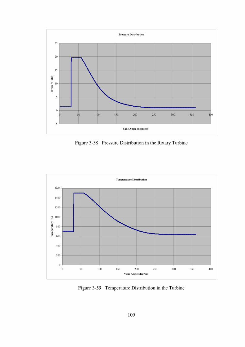
109
Pressure Distribution
-5
0
5
10
15
20
25
0 50 100 150 200 250 300 350 400
Vane Angle (degrees)
Pre
ssu
re (
atm
)
Figure 3-58 Pressure Distribution in the Rotary Turbine
Temperature Distribution
0
200
400
600
800
1000
1200
1400
1600
0 50 100 150 200 250 300 350 400
Vane Angle (degrees)
Tem
per
atu
re (
K)
Figure 3-59 Temperature Distribution in the Turbine
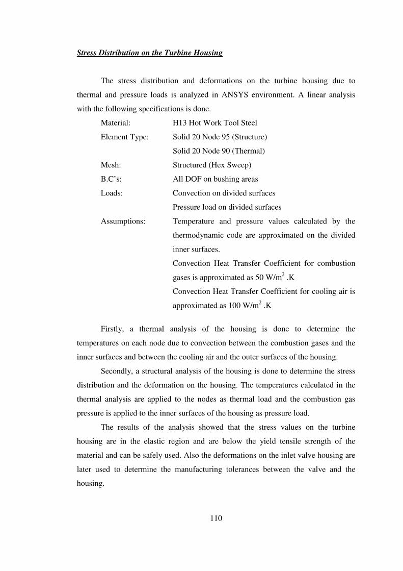
110
Stress Distribution on the Turbine Housing
The stress distribution and deformations on the turbine housing due to
thermal and pressure loads is analyzed in ANSYS environment. A linear analysis
with the following specifications is done.
Material: H13 Hot Work Tool Steel
Element Type: Solid 20 Node 95 (Structure)
Solid 20 Node 90 (Thermal)
Mesh: Structured (Hex Sweep)
B.C’s: All DOF on bushing areas
Loads: Convection on divided surfaces
Pressure load on divided surfaces
Assumptions: Temperature and pressure values calculated by the
thermodynamic code are approximated on the divided
inner surfaces.
Convection Heat Transfer Coefficient for combustion
gases is approximated as 50 W/m2 .K
Convection Heat Transfer Coefficient for cooling air is
approximated as 100 W/m2 .K
Firstly, a thermal analysis of the housing is done to determine the
temperatures on each node due to convection between the combustion gases and the
inner surfaces and between the cooling air and the outer surfaces of the housing.
Secondly, a structural analysis of the housing is done to determine the stress
distribution and the deformation on the housing. The temperatures calculated in the
thermal analysis are applied to the nodes as thermal load and the combustion gas
pressure is applied to the inner surfaces of the housing as pressure load.
The results of the analysis showed that the stress values on the turbine
housing are in the elastic region and are below the yield tensile strength of the
material and can be safely used. Also the deformations on the inlet valve housing are
later used to determine the manufacturing tolerances between the valve and the
housing.
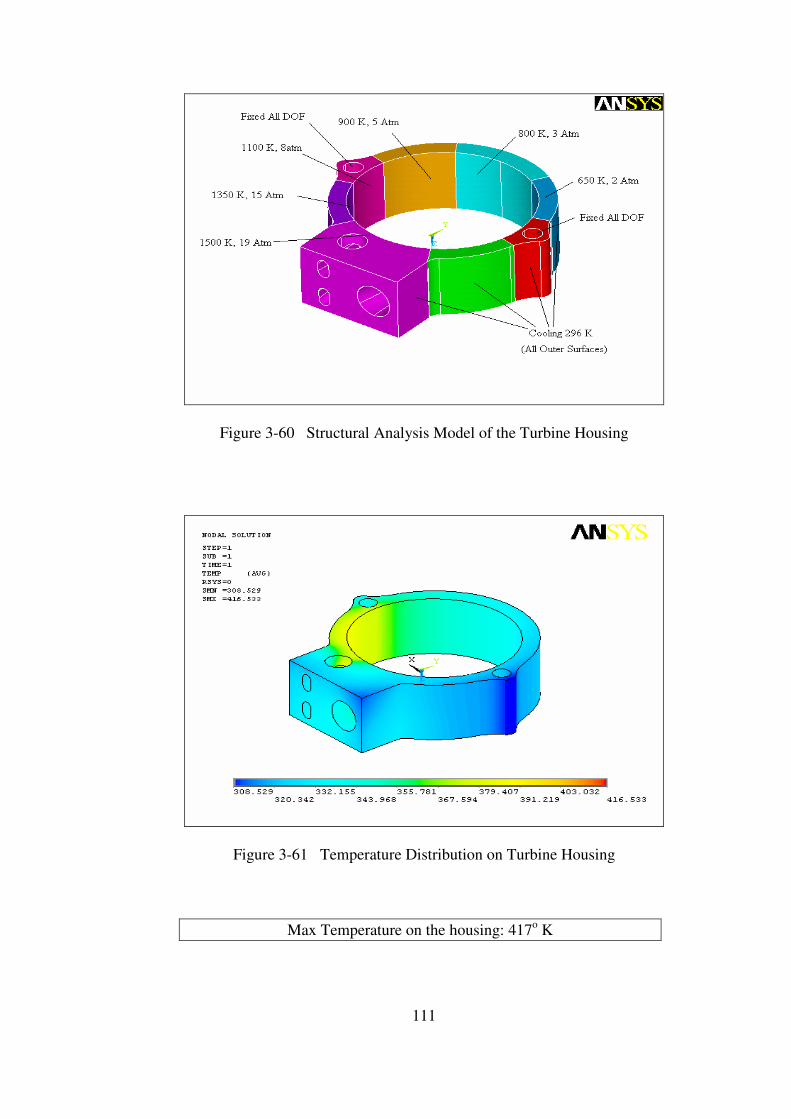
111
Figure 3-60 Structural Analysis Model of the Turbine Housing
Figure 3-61 Temperature Distribution on Turbine Housing
Max Temperature on the housing: 417o K
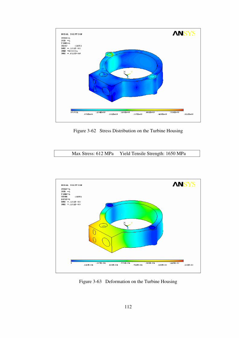
112
Figure 3-62 Stress Distribution on the Turbine Housing
Max Stress: 612 MPa Yield Tensile Strength: 1650 MPa
Figure 3-63 Deformation on the Turbine Housing

113
Stress Distribution on the Turbine Upper Tap
The stress distribution and deformations on the turbine upper tap due to
thermal and pressure loads is analyzed in ANSYS environment. A linear analysis
with the following specifications is done.
Material: H13 Hot Work Tool Steel
Element Type: Solid 20 Node 95 (Structure)
Solid 20 Node 90 (Thermal)
Mesh: Structured (Hex Sweep)
B.C’s: Fixed all DOF on bushing areas
Loads: Convection on divided surfaces
Pressure load on divided surfaces
Assumptions: Temperature and pressure values calculated by the
thermodynamic code are approximated on the divided
inner surfaces.
Convection Heat Transfer Coefficient for combustion
gases is approximated as 50 W/m2 .K
Convection Heat Transfer Coefficient for cooling air is
approximated as 100 W/m2 .K
Firstly, a thermal analysis of the turbine upper tap is done to determine the
temperatures on each node due to convection between the combustion gases and the
inner surfaces and between the cooling air and the outer surfaces of the upper tap.
Secondly, a structural analysis of the turbine upper tap is done to determine
the stress distribution and the deformation on the upper tap. The temperatures
calculated in the thermal analysis are applied to the nodes as thermal load and the
combustion gases pressure is applied to the inner surfaces of the upper tap as
pressure load.
The results of the analysis showed that the stress values on the turbine upper
tap are in the elastic region and are below the yield tensile strength of the material
and can be safely used.
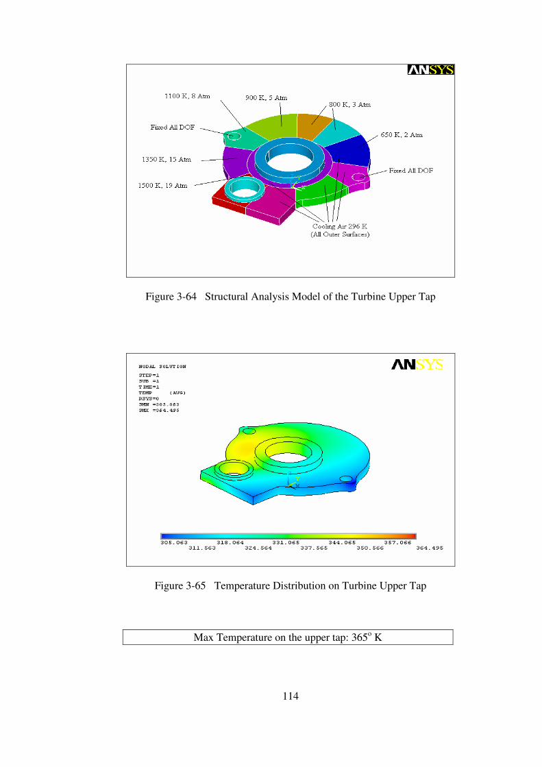
114
Figure 3-64 Structural Analysis Model of the Turbine Upper Tap
Figure 3-65 Temperature Distribution on Turbine Upper Tap
Max Temperature on the upper tap: 365o K
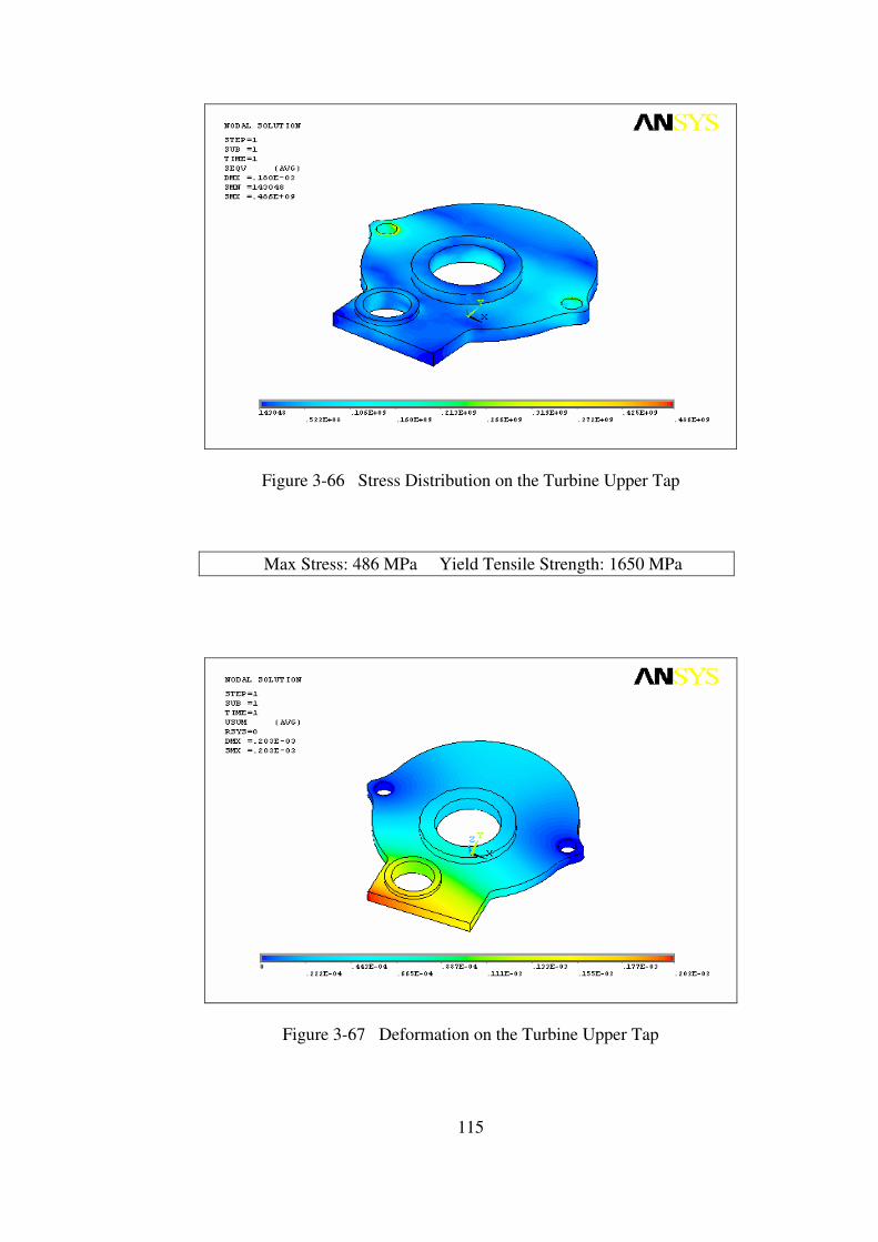
115
Figure 3-66 Stress Distribution on the Turbine Upper Tap
Max Stress: 486 MPa Yield Tensile Strength: 1650 MPa
Figure 3-67 Deformation on the Turbine Upper Tap

116
Stress Distribution on the Turbine Lower Tap
The stress distribution and deformations on the turbine lower tap due to
thermal and pressure loads is analyzed in ANSYS environment. A linear analysis
with the following specifications is done.
Material: H13 Hot Work Tool Steel
Element Type: Solid 20 Node 95 (Structure)
Solid 20 Node 90 (Thermal)
Mesh: Structured (Hex Sweep)
B.C’s: Fixed all DOF on mounting areas
Loads: Convection on divided surfaces
Pressure load on divided surfaces
Assumptions: Temperature and pressure values calculated by the
thermodynamic code are approximated on the divided
inner surfaces.
Convection Heat Transfer Coefficient for combustion
gases is approximated as 50 W/m2 .K
Convection Heat Transfer Coefficient for cooling air is
approximated as 100 W/m2 .K
Firstly, a thermal analysis of the turbine lower tap is done to determine the
temperatures on each node due to convection between the combustion gases and the
inner surfaces and between the cooling air and the outer surfaces of the lower tap.
Secondly, a structural analysis of the turbine lower tap is done to determine
the stress distribution and the deformation on the lower tap. The temperatures
calculated in the thermal analysis are applied to the nodes as thermal load and the
combustion gases pressure is applied to the inner surfaces of the lower tap as
pressure load.
The results of the analysis showed that the stress values on the turbine lower
tap are in the elastic region and are below the yield tensile strength of the material
and can be safely used.

117
Figure 3-68 Structural Analysis Model of the Turbine Lower Tap
Figure 3-69 Temperature Distribution on Turbine Lower Tap
Max Temperature on the lower tap: 374o K
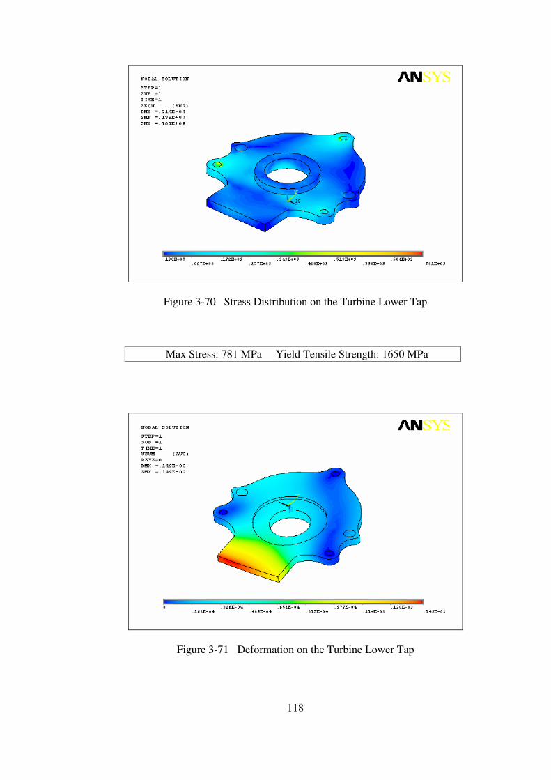
118
Figure 3-70 Stress Distribution on the Turbine Lower Tap
Max Stress: 781 MPa Yield Tensile Strength: 1650 MPa
Figure 3-71 Deformation on the Turbine Lower Tap
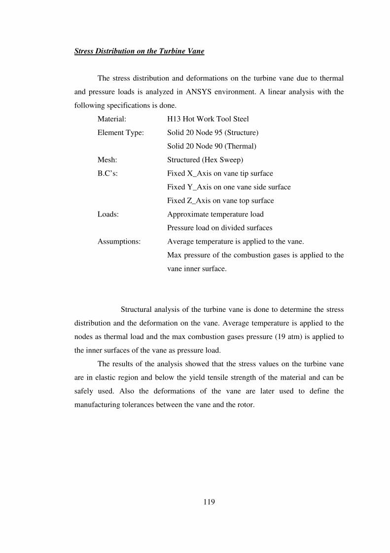
119
Stress Distribution on the Turbine Vane
The stress distribution and deformations on the turbine vane due to thermal
and pressure loads is analyzed in ANSYS environment. A linear analysis with the
following specifications is done.
Material: H13 Hot Work Tool Steel
Element Type: Solid 20 Node 95 (Structure)
Solid 20 Node 90 (Thermal)
Mesh: Structured (Hex Sweep)
B.C’s: Fixed X_Axis on vane tip surface
Fixed Y_Axis on one vane side surface
Fixed Z_Axis on vane top surface
Loads: Approximate temperature load
Pressure load on divided surfaces
Assumptions: Average temperature is applied to the vane.
Max pressure of the combustion gases is applied to the
vane inner surface.
Structural analysis of the turbine vane is done to determine the stress
distribution and the deformation on the vane. Average temperature is applied to the
nodes as thermal load and the max combustion gases pressure (19 atm) is applied to
the inner surfaces of the vane as pressure load.
The results of the analysis showed that the stress values on the turbine vane
are in elastic region and below the yield tensile strength of the material and can be
safely used. Also the deformations of the vane are later used to define the
manufacturing tolerances between the vane and the rotor.
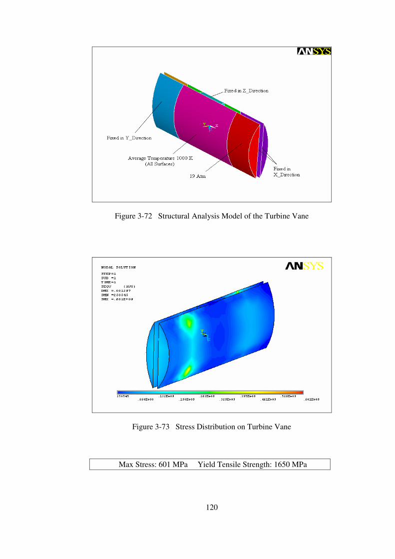
120
Figure 3-72 Structural Analysis Model of the Turbine Vane
Figure 3-73 Stress Distribution on Turbine Vane
Max Stress: 601 MPa Yield Tensile Strength: 1650 MPa
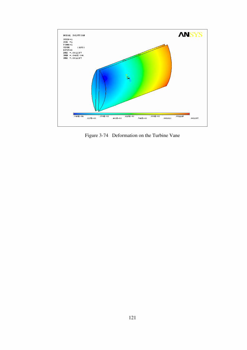
121
Figure 3-74 Deformation on the Turbine Vane
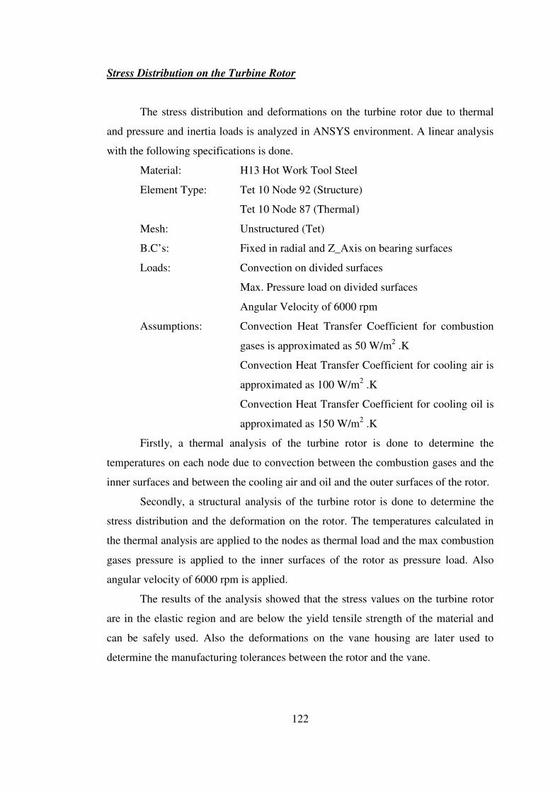
122
Stress Distribution on the Turbine Rotor
The stress distribution and deformations on the turbine rotor due to thermal
and pressure and inertia loads is analyzed in ANSYS environment. A linear analysis
with the following specifications is done.
Material: H13 Hot Work Tool Steel
Element Type: Tet 10 Node 92 (Structure)
Tet 10 Node 87 (Thermal)
Mesh: Unstructured (Tet)
B.C’s: Fixed in radial and Z_Axis on bearing surfaces
Loads: Convection on divided surfaces
Max. Pressure load on divided surfaces
Angular Velocity of 6000 rpm
Assumptions: Convection Heat Transfer Coefficient for combustion
gases is approximated as 50 W/m2 .K
Convection Heat Transfer Coefficient for cooling air is
approximated as 100 W/m2 .K
Convection Heat Transfer Coefficient for cooling oil is
approximated as 150 W/m2 .K
Firstly, a thermal analysis of the turbine rotor is done to determine the
temperatures on each node due to convection between the combustion gases and the
inner surfaces and between the cooling air and oil and the outer surfaces of the rotor.
Secondly, a structural analysis of the turbine rotor is done to determine the
stress distribution and the deformation on the rotor. The temperatures calculated in
the thermal analysis are applied to the nodes as thermal load and the max combustion
gases pressure is applied to the inner surfaces of the rotor as pressure load. Also
angular velocity of 6000 rpm is applied.
The results of the analysis showed that the stress values on the turbine rotor
are in the elastic region and are below the yield tensile strength of the material and
can be safely used. Also the deformations on the vane housing are later used to
determine the manufacturing tolerances between the rotor and the vane.

123
Figure 3-75 Structural Analysis Model of the Turbine Rotor
Figure 3-76 Temperature Distribution on Turbine Rotor
Max Temperature on the rotor: 366o K
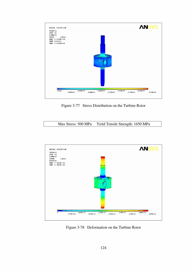
124
Figure 3-77 Stress Distribution on the Turbine Rotor
Max Stress: 500 MPa Yield Tensile Strength: 1650 MPa
Figure 3-78 Deformation on the Turbine Rotor
125
Stress Distribution on the Turbine Inlet Valve
The stress distribution and deformations on the turbine inlet valve due to
thermal and pressure loads is analyzed in ANSYS environment. A linear analysis
with the following specifications is done.
Material: H13 Hot Work Tool Steel
Element Type: Solid 20 Node 95 (Structure)
Solid 20 Node 90 (Thermal)
Mesh: Structured (Hex Sweep)
B.C’s: Fixed in radial and Z_Axis on bearing surfaces
Loads: Convection on divided surfaces
Pressure load on divided surfaces
Angular velocity of 6000 rpm
Assumptions: Convection Heat Transfer Coefficient for combustion
gases is approximated as 50 W/m2 .K
Convection Heat Transfer Coefficient for cooling air is
approximated as 100 W/m2 .K
Firstly, a thermal analysis of the turbine inlet valve is done to determine the
temperatures on each node due to convection between the combustion gases and the
inlet surfaces and between the cooling air and the outer surfaces of the inlet valve.
Secondly, a structural analysis of the turbine inlet valve is done to determine
the stress distribution and the deformation on the inlet valve. The temperatures
calculated in the thermal analysis are applied to the nodes as thermal load and the
max combustion gases pressure is applied to the inlet surfaces of the inlet valve as
pressure load. Also angular velocity of 6000 rpm is applied.
The results of the analysis showed that the stress values on the turbine inlet
valve are in the elastic region and are below the yield tensile strength of the material
and can be safely used. Also the deformations of the valve are later used to define
manufacturing tolerance between the inlet valve and the housing.
126
Figure 3-79 Structural Analysis Model of the Turbine Inlet Valve
Figure 3-80 Temperature Distribution on Turbine Inlet Valve
Max Temperature on the inlet valve: 412o K

127
Figure 3-81 Stress Distribution on the Turbine Inlet Valve
Max Stress: 297 MPa Yield Tensile Strength: 1650 MPa
Figure 3-82 Deformation on the Turbine Inlet Valve
128
Stress Distribution on the Turbine Vane Apex Seal
The stress distribution and deformations on the turbine vane apex seal due to
thermal loads is analyzed in ANSYS environment. A linear analysis with the
following specifications is done.
Material: H13 Hot Work Tool Steel
Element Type: Solid 20 Node 95 (Structure)
Solid 20 Node 90 (Thermal)
Mesh: Structured (Hex Sweep)
B.C’s: Fixed X_Axis on vane apex seal tip surface
Fixed Y_Axis on vane apex seal top surface
Fixed Z_Axis on one vane apex seal side surface
Loads: Approximate temperature load
Assumptions: Average temperature is applied to the vane apex seal.
Structural analysis of the turbine vane apex seal is done to determine
the stress distribution and the deformation on the vane apex seal. Average
temperature (1000 K) is applied to the nodes as thermal load.
The results of the analysis showed that the stress values on the turbine vane
apex seal are in elastic region and much below the yield tensile strength of the
material and can be safely used. Also the deformations of the vane apex seal are later
used to define the manufacturing tolerances between the vane and vane apex seal.
129
Figure 3-83 Structural Analysis Model of the Turbine Vane Apex Seal
Figure 3-84 Stress Distribution on Turbine Vane Apex Seal
Max Stress: 1070 MPa Yield Tensile Strength: 1650 MPa
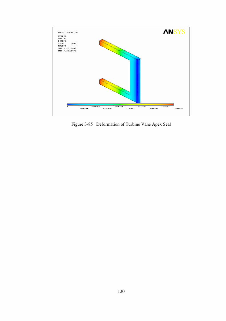
130
Figure 3-85 Deformation of Turbine Vane Apex Seal
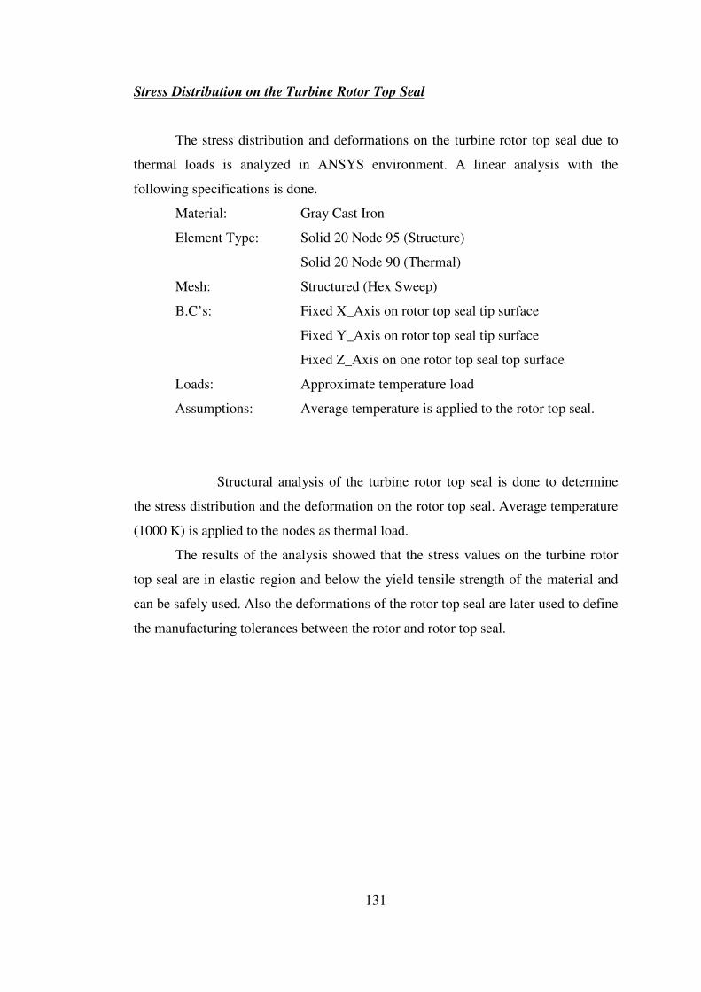
131
Stress Distribution on the Turbine Rotor Top Seal
The stress distribution and deformations on the turbine rotor top seal due to
thermal loads is analyzed in ANSYS environment. A linear analysis with the
following specifications is done.
Material: Gray Cast Iron
Element Type: Solid 20 Node 95 (Structure)
Solid 20 Node 90 (Thermal)
Mesh: Structured (Hex Sweep)
B.C’s: Fixed X_Axis on rotor top seal tip surface
Fixed Y_Axis on rotor top seal tip surface
Fixed Z_Axis on one rotor top seal top surface
Loads: Approximate temperature load
Assumptions: Average temperature is applied to the rotor top seal.
Structural analysis of the turbine rotor top seal is done to determine
the stress distribution and the deformation on the rotor top seal. Average temperature
(1000 K) is applied to the nodes as thermal load.
The results of the analysis showed that the stress values on the turbine rotor
top seal are in elastic region and below the yield tensile strength of the material and
can be safely used. Also the deformations of the rotor top seal are later used to define
the manufacturing tolerances between the rotor and rotor top seal.

132
Figure 3-86 Structural Analysis Model of the Turbine Rotor Top Seal
Figure 3-87 Stress Distribution on Turbine Rotor Top Seal
Max Stress: 1080 MPa Yield Tensile Strength: 1650 MPa
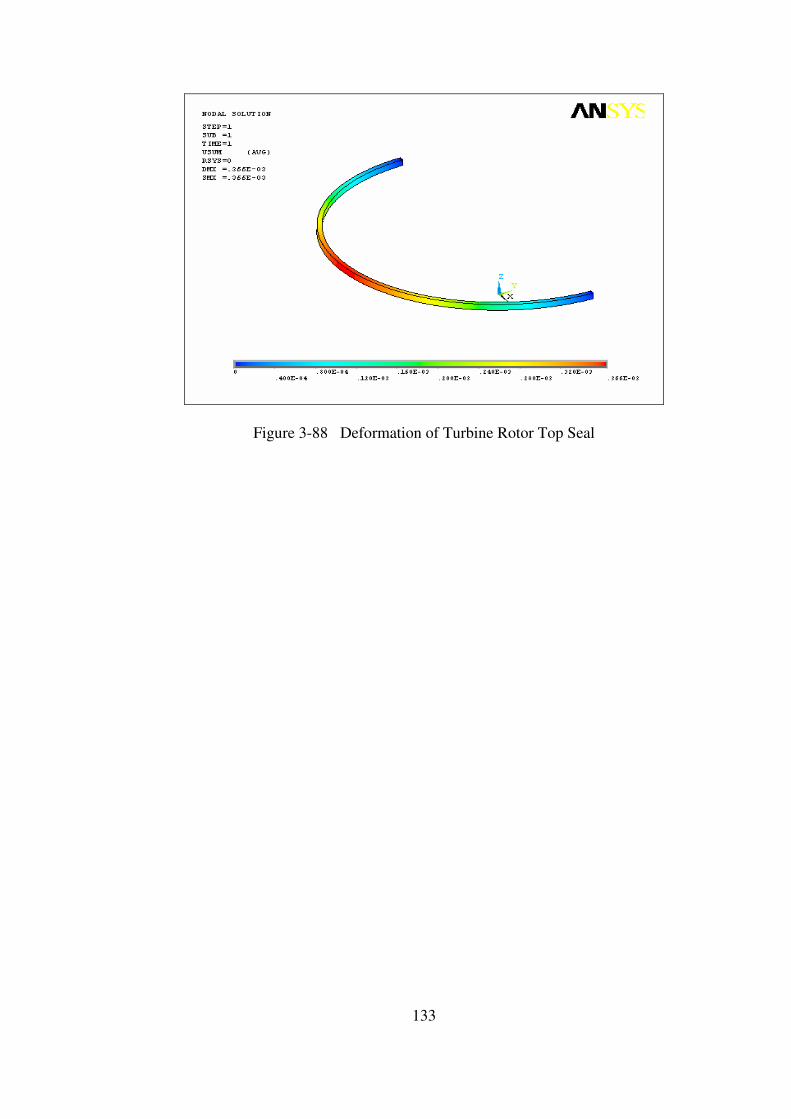
133
Figure 3-88 Deformation of Turbine Rotor Top Seal
134
Manufacturing Tolerance between Inlet Valve and Housing
Due to thermal and pressure loads on the inlet valve and housing surfaces,
deformations on the materials occur. These deformations are examined to determine
the manufacturing tolerances of both parts so that the inlet valve can revolve within
its housing without stacking while still assuring good sealing capacity.
By examining the turbine inlet valve deformation, it is seen that the inlet
valve deforms 0.1 mm max radially.
By examining the turbine housing, it is seen that the inlet valve housing
deforms 0.085 mm max radially.
As a result, 0.185 mm gap tolerance between the inlet valve and the housing
will assure inlet valve to revolve within the housing without stacking. This gap
tolerance can be guaranteed by manufacturing the inlet valve 0.1 mm smaller in
diameter and by opening the valve housing hole 0.085 mm larger in diameter.
Manufacturing Tolerance between Vane and Rotor
Due to thermal and pressure and inertia loads on the vane and rotor surfaces,
deformations on the materials occur. These deformations are examined to determine
the manufacturing tolerances of both parts so that the vane can move within the rotor
without stacking while still assuring good sealing characteristics.
By examining the turbine vane deformation, it is seen that the vane deforms 1
mm max.
By examining the turbine rotor, it is seen that the vane channel deforms 0.2
mm max.
As a result, 1.2 mm gap tolerance between the vane and the rotor will assure
turbine vane to revolve within the rotor without stacking. This gap tolerance can be
guaranteed by manufacturing the turbine vane 1 mm smaller in thickness and by
opening the vane channel 0.2 mm larger in thickness.
135
Manufacturing Tolerance between Vane Apex Seal and Vane
Due to thermal and pressure loads on the vane and vane apex seal surfaces,
deformations on the materials occur. These deformations are examined to determine
the manufacturing tolerances of both parts so that the vane apex seal can move
within the vane without stacking, while still assuring good sealing characteristics.
By examining the turbine vane apex seal deformation, it is seen that the seal
deforms 0.2 mm max in thickness.
By examining the turbine vane, it is seen that the apex seal channel deforms
0.8 mm max in thickness.
As a result, 1 mm gap tolerance between the vane apex seal and the vane will
assure apex seal to move within the channel without stacking. This gap tolerance can
be guaranteed by manufacturing the turbine vane apex seal 0.2 mm smaller in
thickness and by opening the turbine vane seal channel 0.8 mm larger in thickness.
Manufacturing Tolerance between Rotor Top Seal and Rotor
Due to thermal and pressure loads on the rotor and rotor top seal surfaces,
deformations on the materials occur. These deformations are examined to determine
the manufacturing tolerances of both parts so that the rotor top seal can move within
the rotor seal channel without stacking, while still assuring good sealing
characteristics.
By examining the turbine rotor top seal deformation, it is seen that the seal
deforms 0.35 mm max in diameter.
By examining the turbine rotor, it is seen that the rotor top seal channel
deforms 0.1 mm max in thickness.
As a result, 0.135 mm gap tolerance between the rotor top seal and the rotor
seal channel will assure top seal to move within the channel without stacking. This
gap tolerance can be guaranteed by manufacturing the turbine rotor top seal 0.35 mm
smaller in thickness and by opening the turbine rotor top seal channel 0.1 mm larger
in diameter.
136
Turbine Material [24]
With respect to the structural analysis results, H13 Hot Work Tool Steel is
selected as the material of the rotary turbine prototype that will be manufactured. The
selection criteria of the material are given below;
• Excellent wear resistance and hot toughness.
• High thermal shock resistance.
• Good thermal conductivity and tolerate some water cooling in service.
• High temperature tensile strength.
• Good machinability.
Regarding these properties of the material, it is one of the best alternatives that
can be used for the manufacturing of the rotary turbine prototype. Beside these
properties, the structural analysis of the turbine parts is done using this material and
the analysis results showed that the selected material is suitable for the prototype.
(Properties of H13 Hot Work Tool Steel is given in Appendix D)
Turbine Vane Apex Seal Material
Two alternatives for the turbine vane apex seal have been considered.
First alternative for the rotary turbine vane apex seal is H13 hot work tool
steel because of its good mechanical and thermal properties.
However, as the material of the turbine housing is also H13, there would be
great wear deformation on both surfaces of the housing and seal due to friction. By
arranging the hardness of both parts (housing being harder) could decrease the wear
but still it would be over the desired limits of deformation.
The second alternative for the rotary turbine vane apex seal is a tool steel
called Carpenter Pyrowear Alloy 53 Tool Steel. As the temperatures in the rotary
turbine are very high, this material with its good temper resistance, high core impact
strength and fracture toughness together with its excellent temperature resistance
would be a good choice. (Properties of Carpenter Pyrowear is given in Appendix D)
137
Turbine Rotor Top Seals
The best alternative for the rotary turbine rotor top seal is the gray cast iron
which is also used in the piston engines’ piston head seals. Also seal is plated with
chromium to give excellent wear and scuff resistance under very marginal lubrication
conditions. Because of its good wear properties, the deformation on the tap inner
surfaces where the rotor top seals are in contact with, will be minimum while good
sealing will be achieved. (Properties of Gray Cast Iron is given in Appendix D)
Turbine Vane Apex and Rotor Top Seal Springs
Two alternatives for the springs have been considered.
The first alternative for the rotary turbine springs is a cobalt based super-alloy
called Elgiloy Co-Cr-Ni Alloy. It has high strength, ductility, fatigue life and good
mechanical properties. This material is also used in other rotary engine applications
in the market as seal springs. (Properties of Elgiloy is given in Appendix D)
The second alternative for the rotary turbine springs is a nickel based super-
alloy called Inconel 718. It has high strength, ductility, fatigue life and good
mechanical properties. Its excellent relaxation resistance is useful for high-
temperature springs and bolts. The alloy has good resistance to corrosion and
oxidation along with high tensile and creep-rupture properties at temperatures to
about 1300°F (700°C). (Properties of Inconel 718 is given in Appendix D)
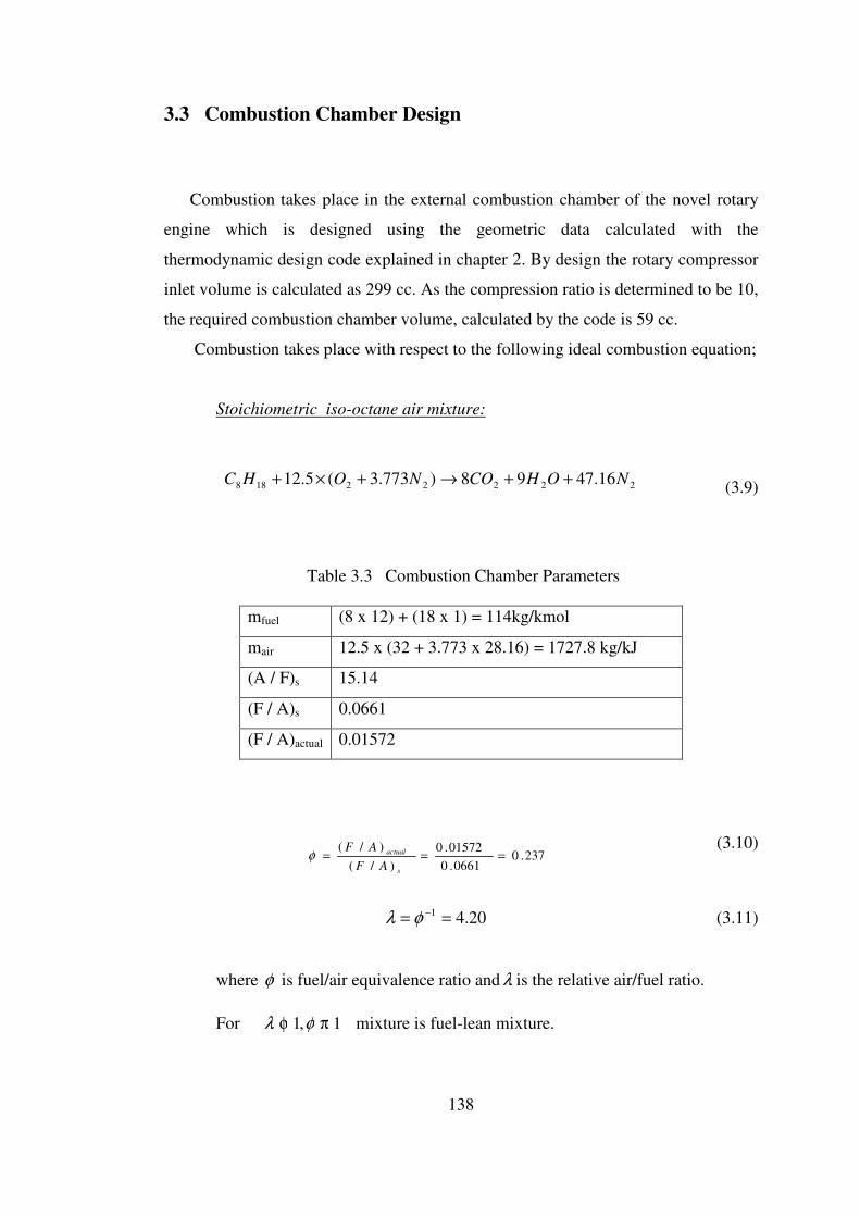
138
3.3 Combustion Chamber Design
Combustion takes place in the external combustion chamber of the novel rotary
engine which is designed using the geometric data calculated with the
thermodynamic design code explained in chapter 2. By design the rotary compressor
inlet volume is calculated as 299 cc. As the compression ratio is determined to be 10,
the required combustion chamber volume, calculated by the code is 59 cc.
Combustion takes place with respect to the following ideal combustion equation;
Stoichiometric iso-octane air mixture:
22222188 16.4798)773.3(5.12 NOHCONOHC ++→+×+ (3.9)
Table 3.3 Combustion Chamber Parameters
mfuel (8 x 12) + (18 x 1) = 114kg/kmol
mair 12.5 x (32 + 3.773 x 28.16) = 1727.8 kg/kJ
(A / F)s 15.14
(F / A)s 0.0661
(F / A)actual 0.01572
237.00661.0
01572.0
)/(
)/(===
s
actual
AF
AFφ
(3.10)
20.41 == −φλ (3.11)
where φ is fuel/air equivalence ratio and λ is the relative air/fuel ratio.
For 1,1 πφ φλ mixture is fuel-lean mixture.
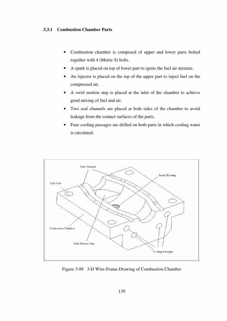
139
3.3.1 Combustion Chamber Parts
• Combustion chamber is composed of upper and lower parts bolted
together with 4 (Metric 8) bolts.
• A spark is placed on top of lower part to ignite the fuel air mixture.
• An injector is placed on the top of the upper part to inject fuel on the
compressed air.
• A swirl motion step is placed at the inlet of the chamber to achieve
good mixing of fuel and air.
• Two seal channels are placed at both sides of the chamber to avoid
leakage from the contact surfaces of the parts.
• Four cooling passages are drilled on both parts in which cooling water
is circulated.
Figure 3-89 3-D Wire-Frame Drawing of Combustion Chamber
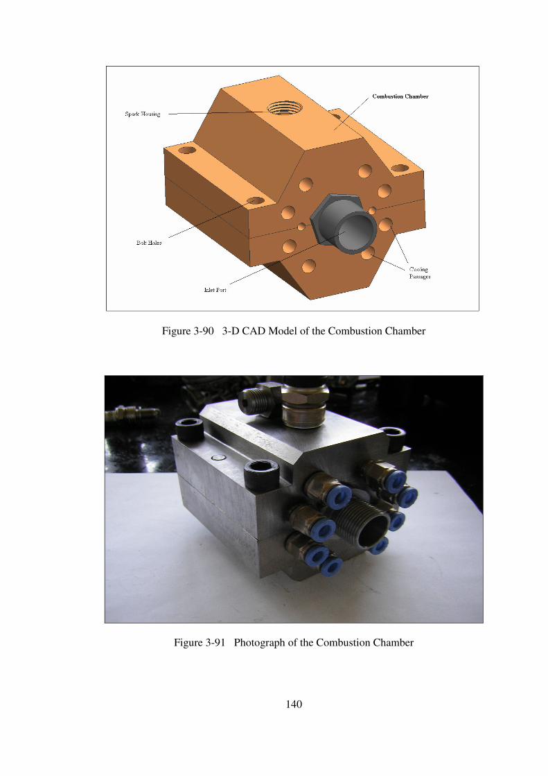
140
Figure 3-90 3-D CAD Model of the Combustion Chamber
Figure 3-91 Photograph of the Combustion Chamber
141
3.3.2 Structural Analysis and Material Selection
Structural analysis of the combustion of the novel engine is done in ANSYS 9.0
Environment (Finite Element Program). The aim of this work is to select the material
of the chamber and to determine the required cooling. To do the structural analysis,
firstly the critical parts are defined as follows;
For material selection;
• Stress distribution on the chamber due to pressure and temperature exerted by the
combustion gases onto the inner surfaces.
For determining the required cooling;
• Stress distribution on the chamber due to pressure and temperature exerted by the
combustion gases onto the inner surfaces while cooling the chamber with cooling
water injected from the cooling passages.
To make the structural analysis of the combustion chamber, the necessary
temperature and pressure data is taken from the thermodynamic design code.
Maximum combustion temperature and pressure is applied to the inner surfaces of
the chamber for safety considerations.
Pmax = 19 atm
Tmax = 1500 K
142
Stress Distribution on the Combustion Chamber
The stress distribution and deformations on the combustion chamber due to
thermal and pressure is analyzed in ANSYS environment. A linear analysis with the
following specifications is done.
Material: H13 Hot Work Tool Steel
Element Type: Solid 20 Node 95 (Structure)
Solid 20 Node 90 (Thermal)
Mesh: Structured (Hex Sweep)
B.C’s: Fixed all DOF on inlet and outlet surfaces
Loads: Convection on divided surfaces
Max. Pressure load on divided surfaces
Assumptions: Convection Heat Transfer Coefficient for combustion
gases is approximated as 50 W/m2 .K
Convection Heat Transfer Coefficient for cooling air is
approximated as 100 W/m2 .K
Convection Heat Transfer Coefficient for cooling water
is approximated as 150 W/m2 .K
Firstly, a thermal analysis of the combustion chamber is done to determine
the temperatures on each node due to convection between the combustion gases and
the inner surfaces and between the cooling air and water and the outer surfaces of the
chamber.
Secondly, a structural analysis of the combustion chamber is done to
determine the stress distribution and the deformation on the chamber. The
temperatures calculated in the thermal analysis are applied to the nodes as thermal
load and the max combustion gases pressure is applied to the inner surfaces of the
chamber as pressure load.
The results of the analysis showed that the stress values on the combustion
chamber are in the elastic region and are below the yield tensile strength of the
material and can be safely used with adequate cooling.
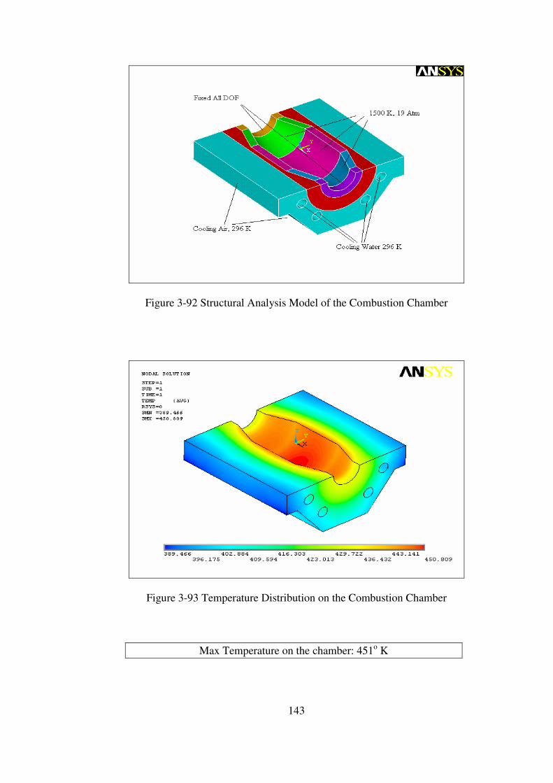
143
Figure 3-92 Structural Analysis Model of the Combustion Chamber
Figure 3-93 Temperature Distribution on the Combustion Chamber
Max Temperature on the chamber: 451o K
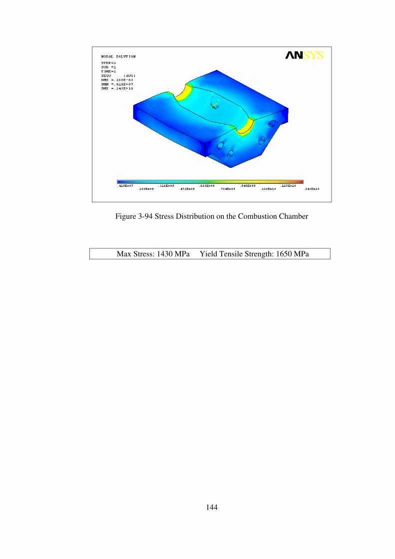
144
Figure 3-94 Stress Distribution on the Combustion Chamber
Max Stress: 1430 MPa Yield Tensile Strength: 1650 MPa
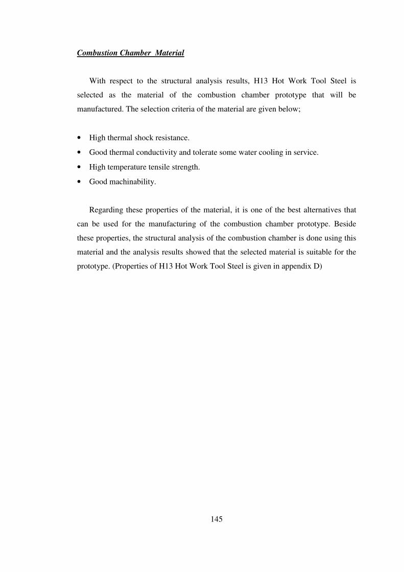
145
Combustion Chamber Material
With respect to the structural analysis results, H13 Hot Work Tool Steel is
selected as the material of the combustion chamber prototype that will be
manufactured. The selection criteria of the material are given below;
• High thermal shock resistance.
• Good thermal conductivity and tolerate some water cooling in service.
• High temperature tensile strength.
• Good machinability.
Regarding these properties of the material, it is one of the best alternatives that
can be used for the manufacturing of the combustion chamber prototype. Beside
these properties, the structural analysis of the combustion chamber is done using this
material and the analysis results showed that the selected material is suitable for the
prototype. (Properties of H13 Hot Work Tool Steel is given in appendix D)
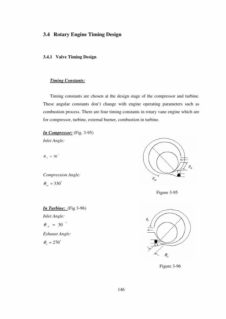
146
3.4 Rotary Engine Timing Design
3.4.1 Valve Timing Design
Timing Constants:
Timing constants are chosen at the design stage of the compressor and turbine.
These angular constants don’t change with engine operating parameters such as
combustion process. There are four timing constants in rotary vane engine which are
for compressor, turbine, external burner, combustion in turbine.
In Compressor: (Fig. 3-95)
Inlet Angle:
°= 30ciθ
Compression Angle:
°= 330ceθ
Figure 3-95
In Turbine: (Fig 3-96)
Inlet Angle:
°= 30tiθ
Exhaust Angle:
°= 270eθ
tiθ
Figure 3-96
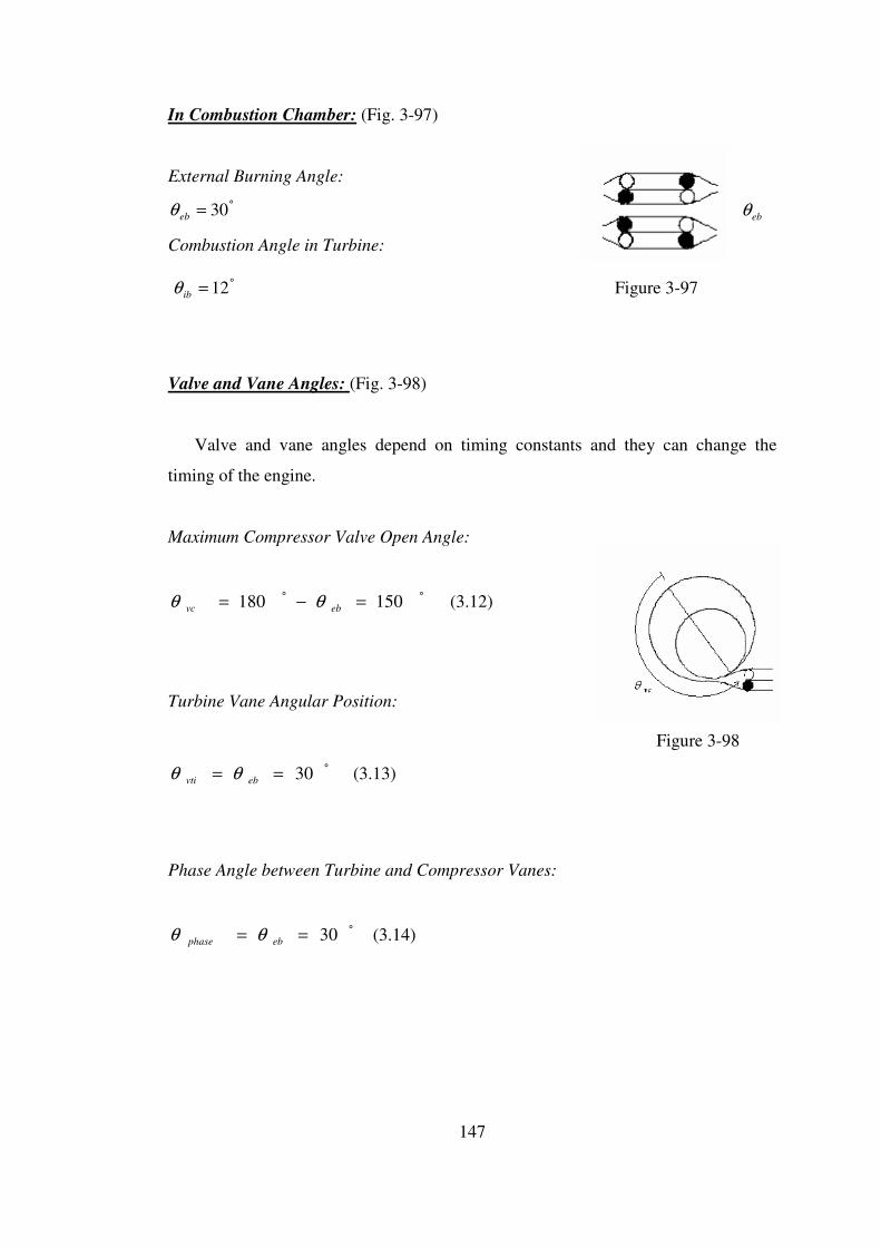
147
In Combustion Chamber: (Fig. 3-97)
External Burning Angle:
°= 30ebθ ebθ
Combustion Angle in Turbine:
°= 12ibθ Figure 3-97
Valve and Vane Angles: (Fig. 3-98)
Valve and vane angles depend on timing constants and they can change the
timing of the engine.
Maximum Compressor Valve Open Angle:
°° =−= 150180 ebvc θθ (3.12)
Turbine Vane Angular Position:
Figure 3-98
°== 30ebvti θθ (3.13)
Phase Angle between Turbine and Compressor Vanes:
°== 30ebphase θθ (3.14)
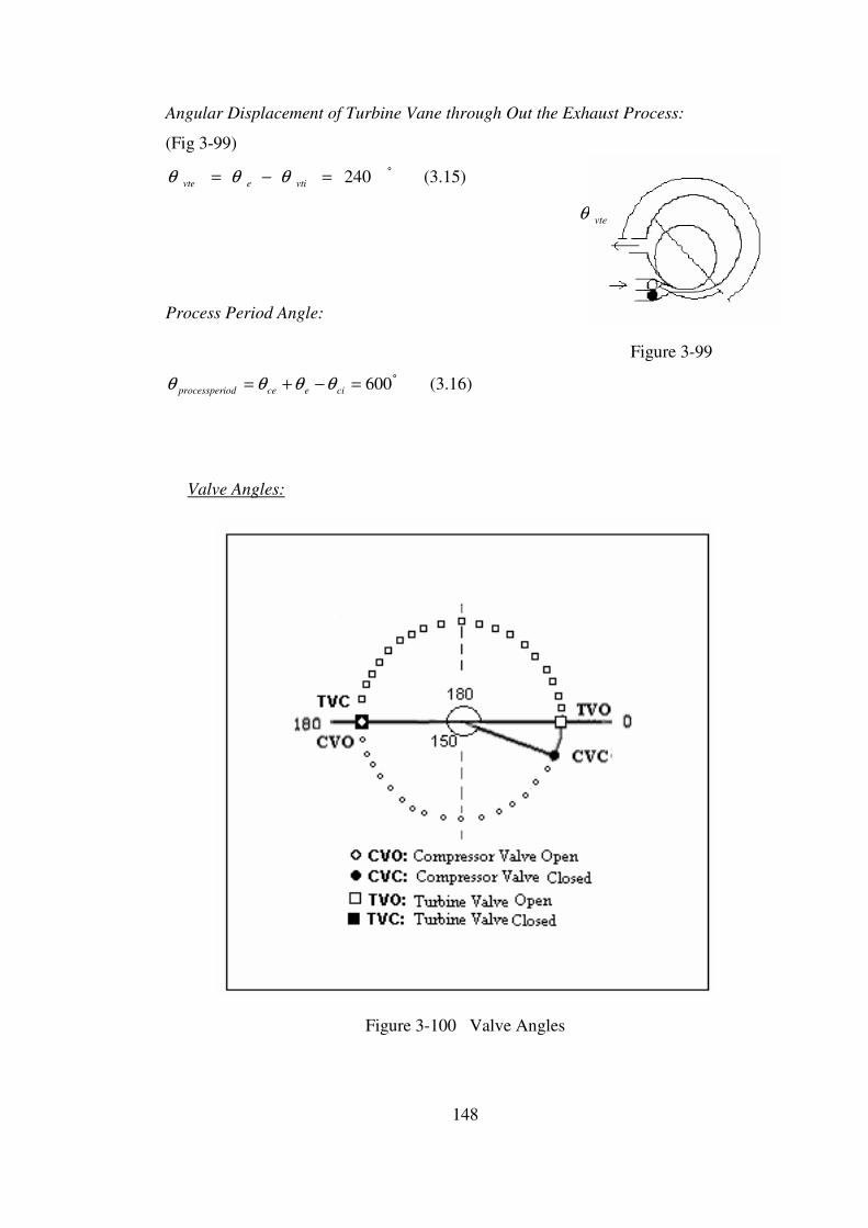
148
Angular Displacement of Turbine Vane through Out the Exhaust Process:
(Fig 3-99)
°=−= 240vtievte θθθ (3.15)
vteθ
Process Period Angle:
Figure 3-99
°=−+= 600cieceiodprocessper θθθθ (3.16)
Valve Angles:
Figure 3-100 Valve Angles

149
TIMING IN ROTARY VANE ENGINE
1) When compressor vane angle is
180 degrees compressor valve
opens and air is compressed to the
first external burner until the vane
angle becomes 330 degree.
2) After 150 degrees from the
opening of the first compressor
valve (compressor vane reaches
330 degrees), the valve closes.
3) Combustion in the first external
burner begins after the compressor
valve is closed and the turbine
valve is opened after 30 degrees
from the closing of the compressor
valve.
4) After the opening of the turbine
valve the combustion gases begin
to expand in the turbine until the
turbine vane reaches 270 degrees at
which exhaust begins.
Figure 3-101 Valve Timing
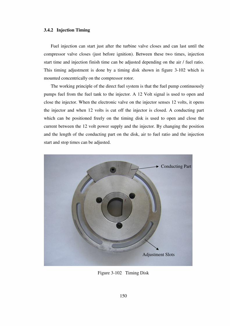
150
3.4.2 Injection Timing
Fuel injection can start just after the turbine valve closes and can last until the
compressor valve closes (just before ignition). Between these two times, injection
start time and injection finish time can be adjusted depending on the air / fuel ratio.
This timing adjustment is done by a timing disk shown in figure 3-102 which is
mounted concentrically on the compressor rotor.
The working principle of the direct fuel system is that the fuel pump continuously
pumps fuel from the fuel tank to the injector. A 12 Volt signal is used to open and
close the injector. When the electronic valve on the injector senses 12 volts, it opens
the injector and when 12 volts is cut off the injector is closed. A conducting part
which can be positioned freely on the timing disk is used to open and close the
current between the 12 volt power supply and the injector. By changing the position
and the length of the conducting part on the disk, air to fuel ratio and the injection
start and stop times can be adjusted.
Conducting Part
Adjustment Slots
Figure 3-102 Timing Disk
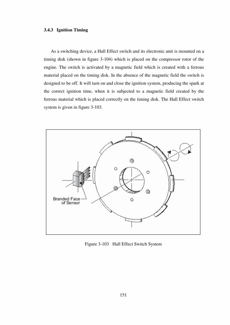
151
3.4.3 Ignition Timing
As a switching device, a Hall Effect switch and its electronic unit is mounted on a
timing disk (shown in figure 3-104) which is placed on the compressor rotor of the
engine. The switch is activated by a magnetic field which is created with a ferrous
material placed on the timing disk. In the absence of the magnetic field the switch is
designed to be off. It will turn on and close the ignition system, producing the spark at
the correct ignition time, when it is subjected to a magnetic field created by the
ferrous material which is placed correctly on the timing disk. The Hall Effect switch
system is given in figure 3-103.
Figure 3-103 Hall Effect Switch System

152
Ferrous Part
Timing Disk
Adjusting Slot
Figure 3-104 Timing Disk
The position of the ferrous part can be adjusted on the timing disk by the help of the
adjustment slots so that the correct ignition timing can be achieved. By design, the
correct ignition time is when the compressor valve closes.
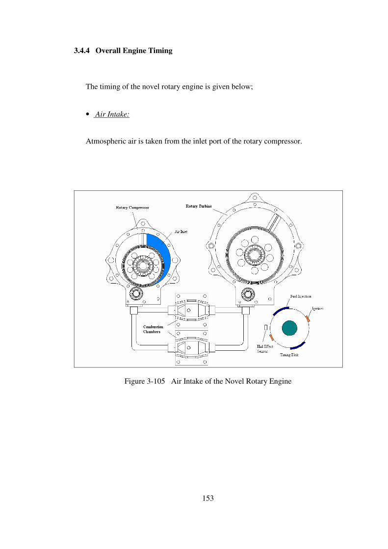
153
3.4.4 Overall Engine Timing
The timing of the novel rotary engine is given below;
• Air Intake:
Atmospheric air is taken from the inlet port of the rotary compressor.
Figure 3-105 Air Intake of the Novel Rotary Engine

154
• Max Air Taken:
When rotary compressor vane reaches 270 degrees the vane passes the
inlet port and the air taken in the compressor for the first stroke is trapped
between the rotor, vane and the housing.
Figure 3-106 Max Air Taken of the Novel Rotary Engine

155
• Air Discharge to First Combustion Chamber:
The trapped intake air is moved through and when rotary compressor
vane reaches 360 degrees the discharge port of the first combustion chamber
is opened and the compressed air (at 2.5 atm) is discharged to the first
combustion chamber for further compression. Air is also being taken in for
the second stroke.
Figure 3-107 Air Discharge of the Novel Rotary Engine
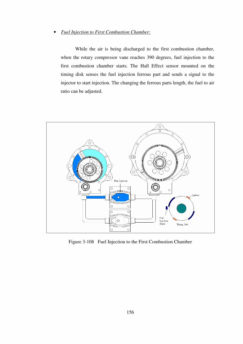
156
• Fuel Injection to First Combustion Chamber:
While the air is being discharged to the first combustion chamber,
when the rotary compressor vane reaches 390 degrees, fuel injection to the
first combustion chamber starts. The Hall Effect sensor mounted on the
timing disk senses the fuel injection ferrous part and sends a signal to the
injector to start injection. The changing the ferrous parts length, the fuel to air
ratio can be adjusted.
Figure 3-108 Fuel Injection to the First Combustion Chamber
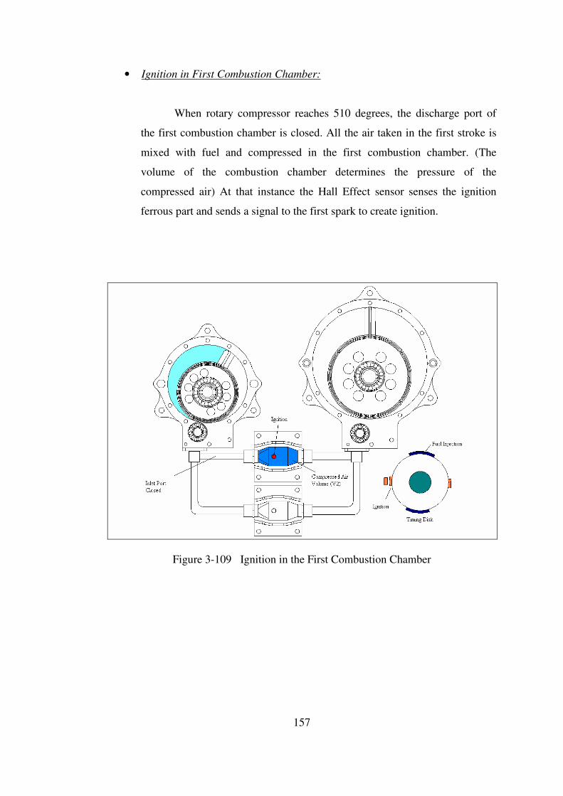
157
• Ignition in First Combustion Chamber:
When rotary compressor reaches 510 degrees, the discharge port of
the first combustion chamber is closed. All the air taken in the first stroke is
mixed with fuel and compressed in the first combustion chamber. (The
volume of the combustion chamber determines the pressure of the
compressed air) At that instance the Hall Effect sensor senses the ignition
ferrous part and sends a signal to the first spark to create ignition.
Figure 3-109 Ignition in the First Combustion Chamber
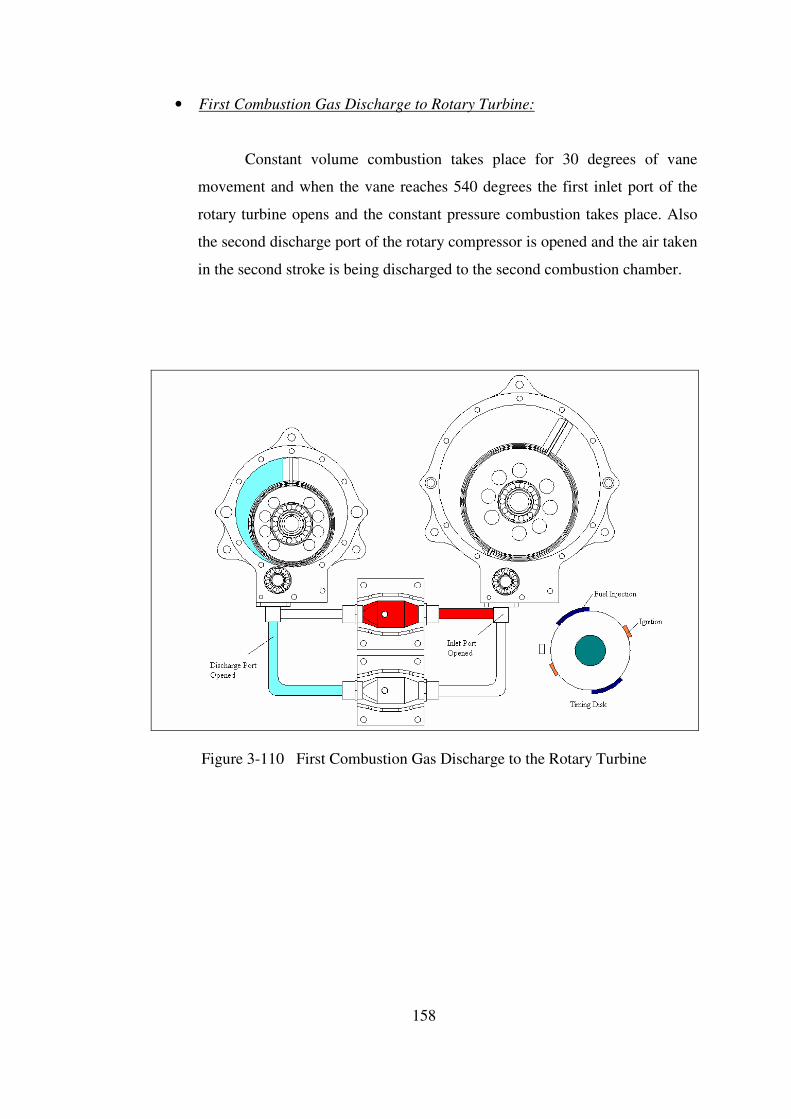
158
• First Combustion Gas Discharge to Rotary Turbine:
Constant volume combustion takes place for 30 degrees of vane
movement and when the vane reaches 540 degrees the first inlet port of the
rotary turbine opens and the constant pressure combustion takes place. Also
the second discharge port of the rotary compressor is opened and the air taken
in the second stroke is being discharged to the second combustion chamber.
Figure 3-110 First Combustion Gas Discharge to the Rotary Turbine
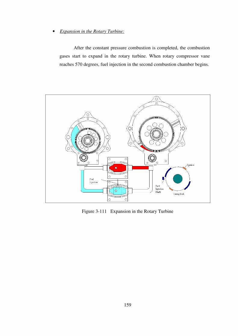
159
• Expansion in the Rotary Turbine:
After the constant pressure combustion is completed, the combustion
gases start to expand in the rotary turbine. When rotary compressor vane
reaches 570 degrees, fuel injection in the second combustion chamber begins.
Figure 3-111 Expansion in the Rotary Turbine
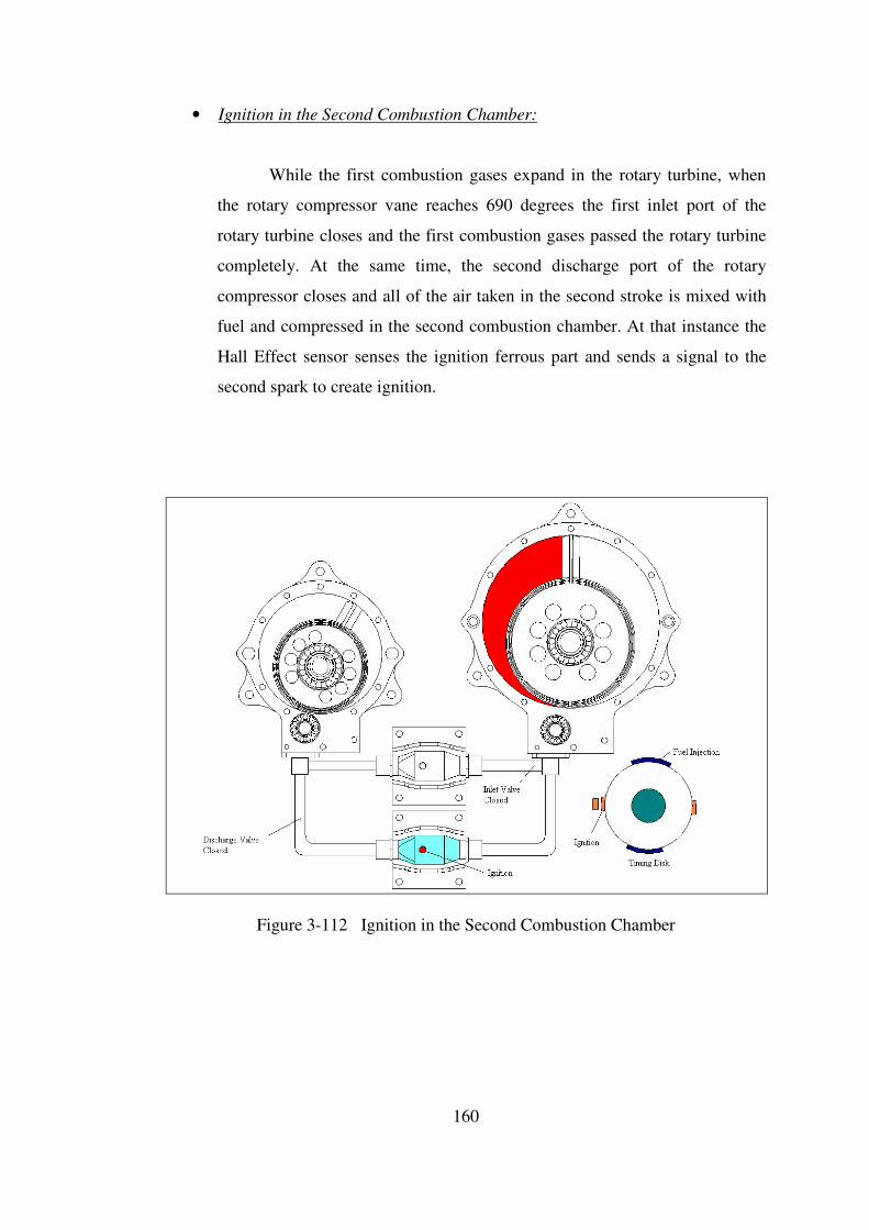
160
• Ignition in the Second Combustion Chamber:
While the first combustion gases expand in the rotary turbine, when
the rotary compressor vane reaches 690 degrees the first inlet port of the
rotary turbine closes and the first combustion gases passed the rotary turbine
completely. At the same time, the second discharge port of the rotary
compressor closes and all of the air taken in the second stroke is mixed with
fuel and compressed in the second combustion chamber. At that instance the
Hall Effect sensor senses the ignition ferrous part and sends a signal to the
second spark to create ignition.
Figure 3-112 Ignition in the Second Combustion Chamber
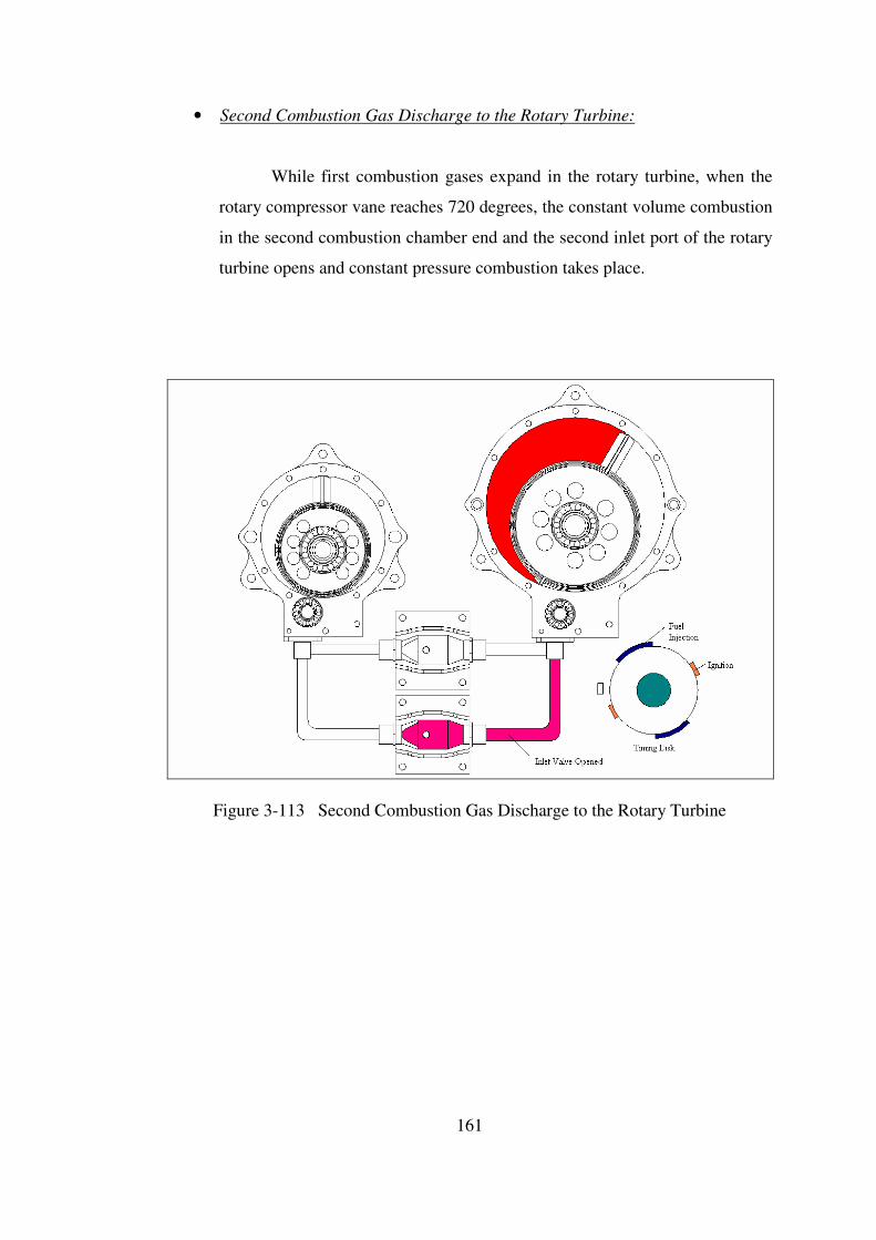
161
• Second Combustion Gas Discharge to the Rotary Turbine:
While first combustion gases expand in the rotary turbine, when the
rotary compressor vane reaches 720 degrees, the constant volume combustion
in the second combustion chamber end and the second inlet port of the rotary
turbine opens and constant pressure combustion takes place.
Figure 3-113 Second Combustion Gas Discharge to the Rotary Turbine
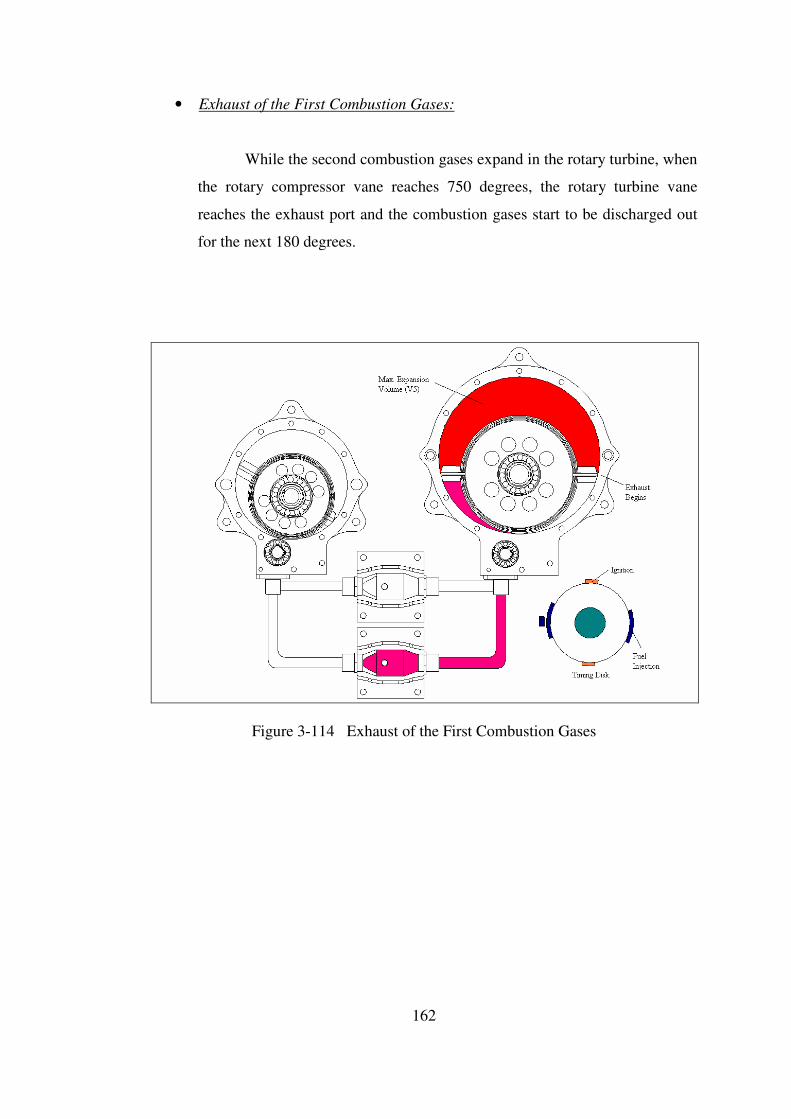
162
• Exhaust of the First Combustion Gases:
While the second combustion gases expand in the rotary turbine, when
the rotary compressor vane reaches 750 degrees, the rotary turbine vane
reaches the exhaust port and the combustion gases start to be discharged out
for the next 180 degrees.
Figure 3-114 Exhaust of the First Combustion Gases
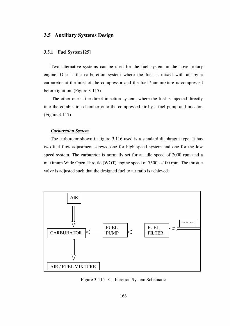
163
3.5 Auxiliary Systems Design
3.5.1 Fuel System [25]
Two alternative systems can be used for the fuel system in the novel rotary
engine. One is the carburetion system where the fuel is mixed with air by a
carburetor at the inlet of the compressor and the fuel / air mixture is compressed
before ignition. (Figure 3-115)
The other one is the direct injection system, where the fuel is injected directly
into the combustion chamber onto the compressed air by a fuel pump and injector.
(Figure 3-117)
Carburetion System
The carburetor shown in figure 3.116 used is a standard diaphragm type. It has
two fuel flow adjustment screws, one for high speed system and one for the low
speed system. The carburetor is normally set for an idle speed of 2000 rpm and a
maximum Wide Open Throttle (WOT) engine speed of 7500 +-100 rpm. The throttle
valve is adjusted such that the designed fuel to air ratio is achieved.
Figure 3-115 Carburetion System Schematic
FUEL
FILTER
FROM TANK
FUEL
PUMP CARBURATOR
AIR / FUEL MIXTURE
AIR

164
Ram Pipe
Compressor Inlet
Air Inlet
Fuel Inlet
Flow Adjustment Screws
Figure 3-116 Carburetor
Direct Injection System
An injector pump shown in figure 3.118 and a multi-hole injector shown in figure
3.119 are used to spray the fuel directly into the combustion chamber onto the
compressed air. The momentum and the energy of the injected fuel jets are sufficient
to achieve adequate fuel distribution and rates of mixing with the air. Additional air
motion is not required. The fuel is injected into the combustion chamber just after the
turbine valve closes which will help to cool the chamber while vaporizing the fuel.
Fuel injection can be completed in minimum 30 degrees to maximum 150 degrees
which can guarantee a proper mixing before ignition. A fuel pump with a maximum
pumping pressure of 10 atm is used to pump the fuel to the injector where the fuel is
sprayed onto a compressed air with a pressure of min 2.5 atm to maximum10 atm.
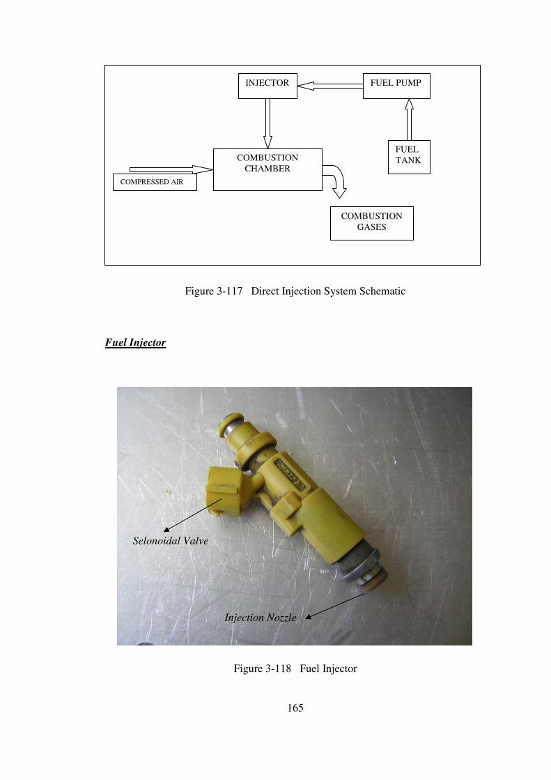
165
Figure 3-117 Direct Injection System Schematic
Fuel Injector
Selonoidal Valve
Injection Nozzle
Figure 3-118 Fuel Injector
COMBUSTION
CHAMBER
COMPRESSED AIR
INJECTOR FUEL PUMP
FUEL
TANK
COMBUSTION
GASES
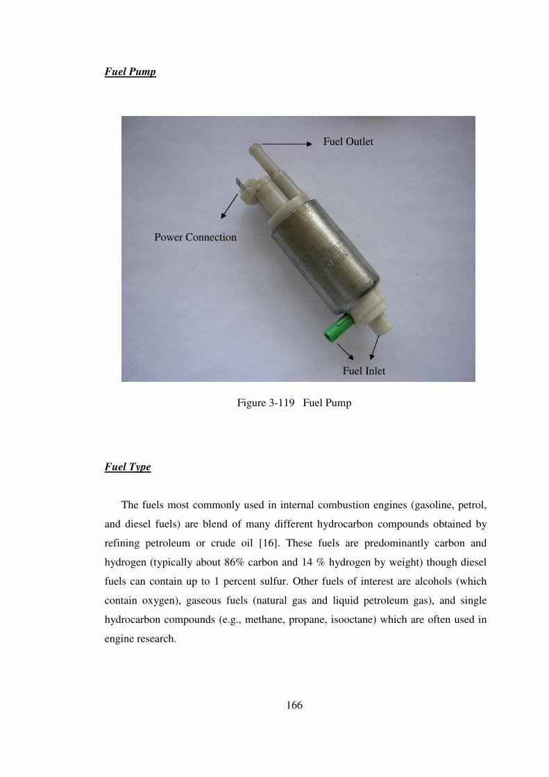
166
Fuel Pump
Fuel Outlet
Power Connection
Fuel Inlet
Figure 3-119 Fuel Pump
Fuel Type
The fuels most commonly used in internal combustion engines (gasoline, petrol,
and diesel fuels) are blend of many different hydrocarbon compounds obtained by
refining petroleum or crude oil [16]. These fuels are predominantly carbon and
hydrogen (typically about 86% carbon and 14 % hydrogen by weight) though diesel
fuels can contain up to 1 percent sulfur. Other fuels of interest are alcohols (which
contain oxygen), gaseous fuels (natural gas and liquid petroleum gas), and single
hydrocarbon compounds (e.g., methane, propane, isooctane) which are often used in
engine research.

167
3.5.2 Lubrication System [26, 27]
The lubricant and the lubricating system perform the following functions;
• Reduce the frictional resistance of the engine to a minimum to ensure maximum
mechanical efficiency.
• Protect the engine against wear.
• Contribute to cooling of the cylinder and regions of the engine where friction
work is dissipated.
• Remove all injurious impurities from lubricated regions.
• Hold gas and leakage (especially between the vane and the cylinder) at an
acceptable minimum level.
Lubrication of the engine is effected by four outlet metering pump shown in
Figure 3-120 with two pairs of high and low outputs.
The high outputs feed oil to the compressor and turbine main bearings. Oil,
coming to top main bearing passes through the rotor while lubricating the rotor top
seals, and reach to the bottom main bearing.
The two low outputs feed oil directly into the cylinder from the cylinder – rotor
tangent point, lubricating the apex seals and forming a thin oil film layer on the
cylinder surfaces. (Figure 3-122)
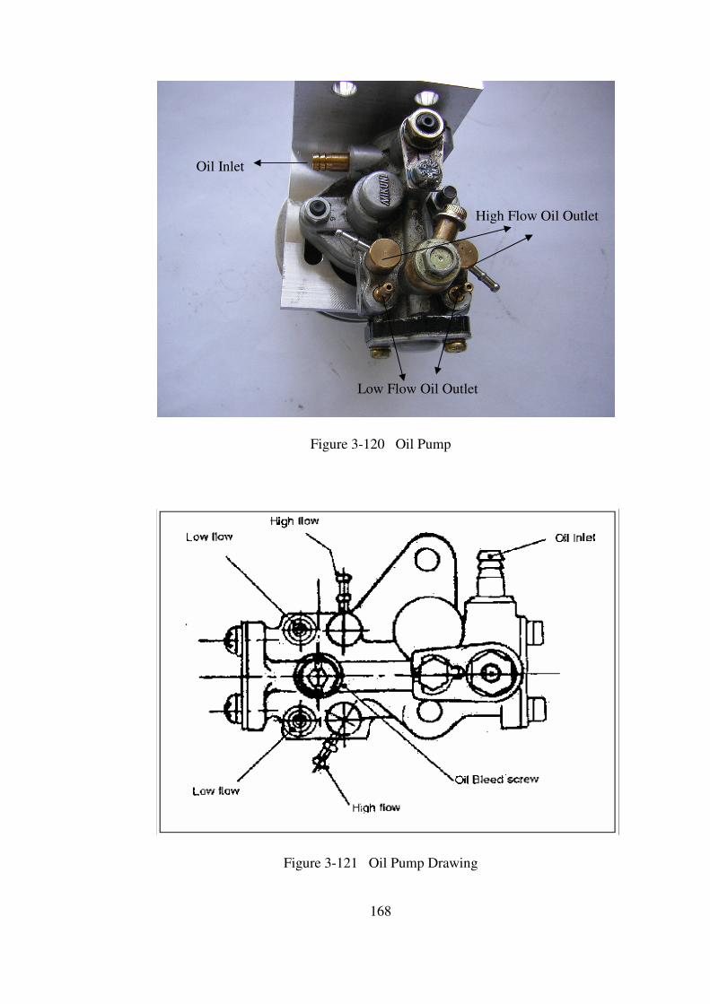
168
Oil Inlet
High Flow Oil Outlet
Low Flow Oil Outlet
Figure 3-120 Oil Pump
Figure 3-121 Oil Pump Drawing
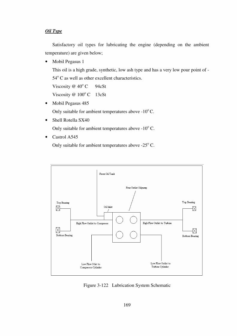
169
Oil Type
Satisfactory oil types for lubricating the engine (depending on the ambient
temperature) are given below;
• Mobil Pegasus 1
This oil is a high grade, synthetic, low ash type and has a very low pour point of -
54o C as well as other excellent characteristics.
Viscosity @ 40o C 94cSt
Viscosity @ 100o C 13cSt
• Mobil Pegasus 485
Only suitable for ambient temperatures above -10o C.
• Shell Rotella SX40
Only suitable for ambient temperatures above -10o C.
• Castrol A545
Only suitable for ambient temperatures above -25o C.
Figure 3-122 Lubrication System Schematic

170
3.5.3 Ignition System
In spark ignition engines, the electrical discharge produced between the spark
plug electrodes by the ignition system starts the combustion process. A spark can arc
from one electrode to another when sufficiently high voltage is applied. Ignition
system used in this engine to provide the necessary spark is the battery system where
the spark energy is stored in a capacitor and transferred as a high voltage pulse to the
spark plug by means of a special transformer which is called as capacitive discharge
ignition system shown in figure 3-123
Figure 3-123 Capacitive Discharge Ignition System
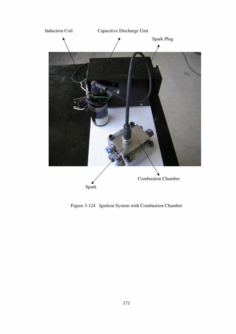
171
Induction Coil Capacitive Discharge Unit
Spark Plug
Combustion Chamber
Spark
Figure 3-124 Ignition System with Combustion Chamber
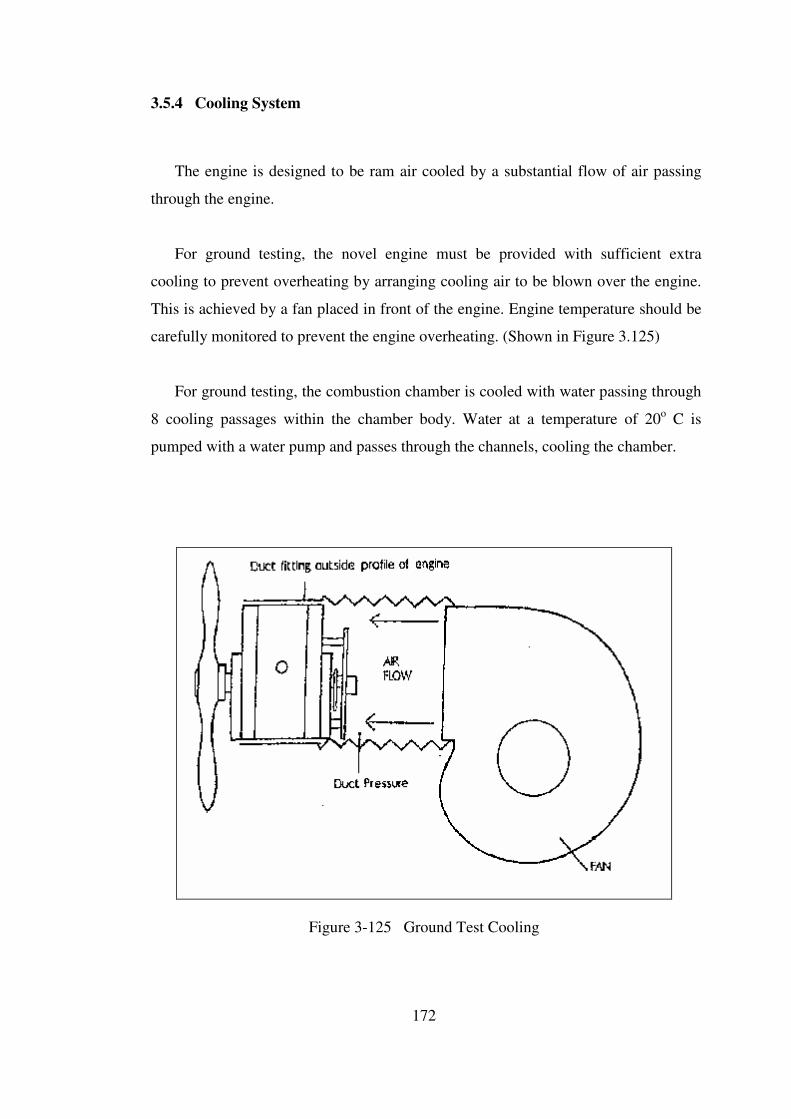
172
3.5.4 Cooling System
The engine is designed to be ram air cooled by a substantial flow of air passing
through the engine.
For ground testing, the novel engine must be provided with sufficient extra
cooling to prevent overheating by arranging cooling air to be blown over the engine.
This is achieved by a fan placed in front of the engine. Engine temperature should be
carefully monitored to prevent the engine overheating. (Shown in Figure 3.125)
For ground testing, the combustion chamber is cooled with water passing through
8 cooling passages within the chamber body. Water at a temperature of 20o C is
pumped with a water pump and passes through the channels, cooling the chamber.
Figure 3-125 Ground Test Cooling

173
3.6 Overall Engine Assembly
The assembly sequence of the designed novel rotary engine is given in figure
3-126.
Figure 3-126 Overall Engine Assembly Scheme
• Compressor and turbine sub-assemblies are coupled with each other from
their rotors with the help of a coupling.
• Two combustion chamber assemblies are mounted in between the
compressor and turbine.
• The whole assembly is mounted on a test stand for ground tests.
• Compressor is coupled with a 2 kW electric motor from the drive side of
the rotor for initial starting of the engine.

174
Figure 3-127 3-D Wire-Frame Drawing of Overall Engine Assembly
Figure 3-128 3-D CAD Model of Overall Engine Assembly
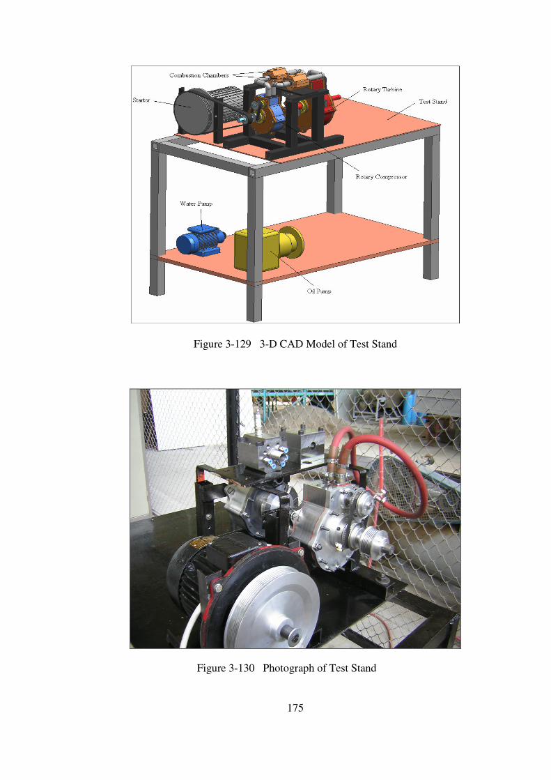
175
Figure 3-129 3-D CAD Model of Test Stand
Figure 3-130 Photograph of Test Stand
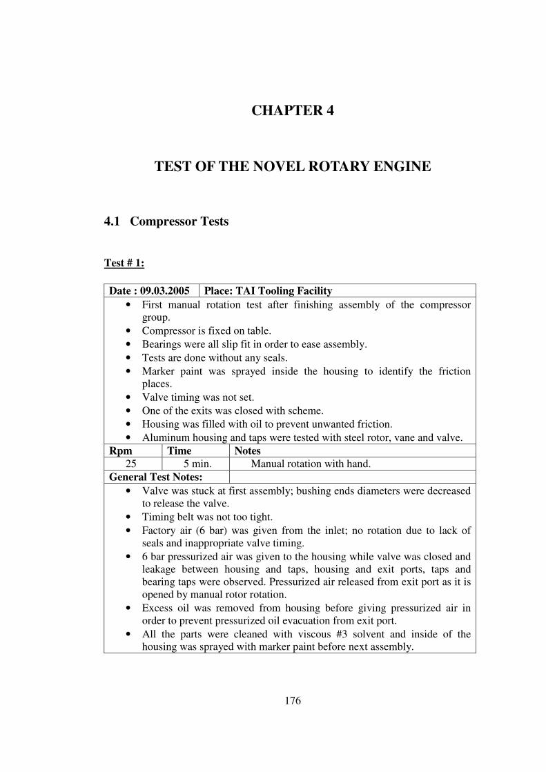
176
CHAPTER 4
TEST OF THE NOVEL ROTARY ENGINE
4.1 Compressor Tests
Test # 1:
Date : 09.03.2005 Place: TAI Tooling Facility
• First manual rotation test after finishing assembly of the compressor
group.
• Compressor is fixed on table.
• Bearings were all slip fit in order to ease assembly.
• Tests are done without any seals.
• Marker paint was sprayed inside the housing to identify the friction
places.
• Valve timing was not set.
• One of the exits was closed with scheme.
• Housing was filled with oil to prevent unwanted friction.
• Aluminum housing and taps were tested with steel rotor, vane and valve.
Rpm Time Notes 25 5 min. Manual rotation with hand.
General Test Notes:
• Valve was stuck at first assembly; bushing ends diameters were decreased
to release the valve.
• Timing belt was not too tight.
• Factory air (6 bar) was given from the inlet; no rotation due to lack of
seals and inappropriate valve timing.
• 6 bar pressurized air was given to the housing while valve was closed and
leakage between housing and taps, housing and exit ports, taps and
bearing taps were observed. Pressurized air released from exit port as it is
opened by manual rotor rotation.
• Excess oil was removed from housing before giving pressurized air in
order to prevent pressurized oil evacuation from exit port.
• All the parts were cleaned with viscous #3 solvent and inside of the
housing was sprayed with marker paint before next assembly.

177
Test # 2:
Date : 10.03.2005 Place: TAI Machining Facility
• First rotary test after finishing assembly of the compressor group.
• Compressor is fixed on the test tool and mounted on a horizontal
machining center with a spindle of max 1200 rpm.
• Tests are done without any seals.
• Marker paint was sprayed inside the housing to identify the friction
places.
• Valve timing was set with timing pulleys and belt.
• Housing was filled with oil to prevent unwanted friction.
• Aluminum housing and taps were tested with steel rotor, vane and valve.
Rpm Time Notes 25 1 min. Normal working.
150 1 min. Normal working.
325 1 min. Normal working.
570 1 min. Slight vibration started.
Bolts attaching test tool and table were tightened.
Vibration diminished.
730 1 min. Color of the oil coming out of the housing was
changed.
Oil became darker and tiny aluminum pieces
were observed with the oil.
940 1 min. Normal working.
1200 1 min. Slight temperature rise on the bottom half of the
housing were friction is max.
No temperature rise on the upper half of the
housing.
General Test Notes:
• Vibration and noise were normal although it was tested without seals.
• Valve timing seemed to be accurate.
• Pressure at both exits seemed to be same.
• Balloons were attached to the exits and were filled with compressed air-
oil mixture till they explode.
• Compressor assembly was demounted at the end of the test. It was
observed that at the bottom half of the housing, all the paint was removed.
Also the paint on the tangent point between rotor and housing was
completely removed. Aluminum pieces were observed inside the housing
and some were stick on the vane. Inside the housing, distance between the
two bushings was measured at 3 different heights with bore-gage.
• Thicker oil seemed to be more appropriate for tests then the used one.
• All the parts were cleaned with viscous #3 solvent and inside of the
housing was sprayed with marker paint before assembly.
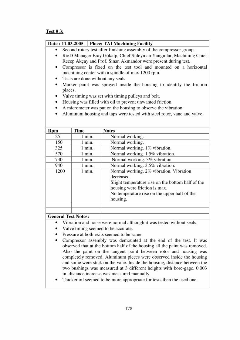
178
Test # 3:
Date : 11.03.2005 Place: TAI Machining Facility
• Second rotary test after finishing assembly of the compressor group.
• R&D Manager Eray Gökalp, Chief Süleyman Yangınlar, Machining Chief
Recep Akçay and Prof. Sinan Akmandor were present during test.
• Compressor is fixed on the test tool and mounted on a horizontal
machining center with a spindle of max 1200 rpm.
• Tests are done without any seals.
• Marker paint was sprayed inside the housing to identify the friction
places.
• Valve timing was set with timing pulleys and belt.
• Housing was filled with oil to prevent unwanted friction.
• A micrometer was put on the housing to observe the vibration.
• Aluminum housing and taps were tested with steel rotor, vane and valve.
Rpm Time Notes
25 1 min. Normal working.
150 1 min. Normal working.
325 1 min. Normal working. 1% vibration.
570 1 min. Normal working. 1.5% vibration.
730 1 min. Normal working. 3% vibration.
940 1 min. Normal working. 3.5% vibration.
1200 1 min. Normal working. 2% vibration. Vibration
decreased.
Slight temperature rise on the bottom half of the
housing were friction is max.
No temperature rise on the upper half of the
housing.
General Test Notes:
• Vibration and noise were normal although it was tested without seals.
• Valve timing seemed to be accurate.
• Pressure at both exits seemed to be same.
• Compressor assembly was demounted at the end of the test. It was
observed that at the bottom half of the housing all the paint was removed.
Also the paint on the tangent point between rotor and housing was
completely removed. Aluminum pieces were observed inside the housing
and some were stick on the vane. Inside the housing, distance between the
two bushings was measured at 3 different heights with bore-gage. 0.003
in. distance increase was measured manually.
• Thicker oil seemed to be more appropriate for tests then the used one.
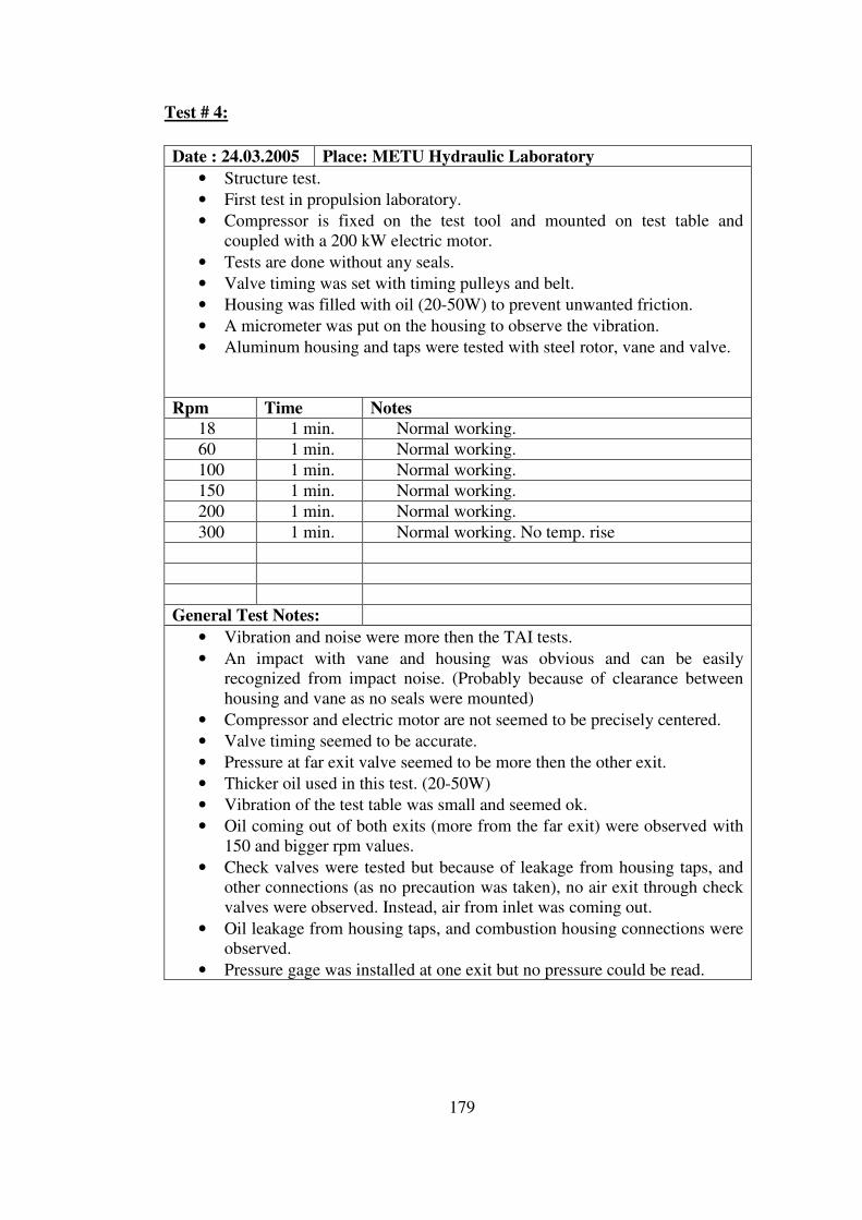
179
Test # 4:
Date : 24.03.2005 Place: METU Hydraulic Laboratory
• Structure test.
• First test in propulsion laboratory.
• Compressor is fixed on the test tool and mounted on test table and
coupled with a 200 kW electric motor.
• Tests are done without any seals.
• Valve timing was set with timing pulleys and belt.
• Housing was filled with oil (20-50W) to prevent unwanted friction.
• A micrometer was put on the housing to observe the vibration.
• Aluminum housing and taps were tested with steel rotor, vane and valve.
Rpm Time Notes 18 1 min. Normal working.
60 1 min. Normal working.
100 1 min. Normal working.
150 1 min. Normal working.
200 1 min. Normal working.
300 1 min. Normal working. No temp. rise
General Test Notes:
• Vibration and noise were more then the TAI tests.
• An impact with vane and housing was obvious and can be easily
recognized from impact noise. (Probably because of clearance between
housing and vane as no seals were mounted)
• Compressor and electric motor are not seemed to be precisely centered.
• Valve timing seemed to be accurate.
• Pressure at far exit valve seemed to be more then the other exit.
• Thicker oil used in this test. (20-50W)
• Vibration of the test table was small and seemed ok.
• Oil coming out of both exits (more from the far exit) were observed with
150 and bigger rpm values.
• Check valves were tested but because of leakage from housing taps, and
other connections (as no precaution was taken), no air exit through check
valves were observed. Instead, air from inlet was coming out.
• Oil leakage from housing taps, and combustion housing connections were
observed.
• Pressure gage was installed at one exit but no pressure could be read.

180
Test # 5:
Date : 25.03.2005 Place: METU Hydraulic Laboratory
• Structure test.
• Second test in propulsion laboratory.
• Compressor is fixed on the test tool and mounted on test table and
coupled with a 200 kW electric motor.
• Last day’s setup was used as the compressor was not demounted after the
test.
• Tests are done without any seals.
• Nazmi Ersöz (patent partner) was also participating to the tests.
• Electric motor and compressor were re-centered before the test.
• 1st Prototype (manufactured in 1st DLMM in Eskişehir) was also tested.
Rpm Time Notes 18 1 min. Normal working.
60 1 min. Normal working.
100 1 min. Normal working.
General Test Notes:
• Valve timing seemed to be accurate.
• Thicker oil used in this test. (20-50W)
• Vibration of the test table was small and seemed ok.
• Compressor assembly was demounted at the end of the test.
• While inspecting the vane seals, it was found out that they were false
manufactured. They were 1.5 mm short in height. (57.80mm instead of
59.3 mm) and it was decided that they were to be re-made.
• Springs were examined and they were seemed to be a bit stiffer.
• Also top rotor seals seemed to be tight fit.
• Compressed air (10 bars) was given to the turbine of 1st prototype and it
started rotating at an approximate of 50 – 75 rpm.
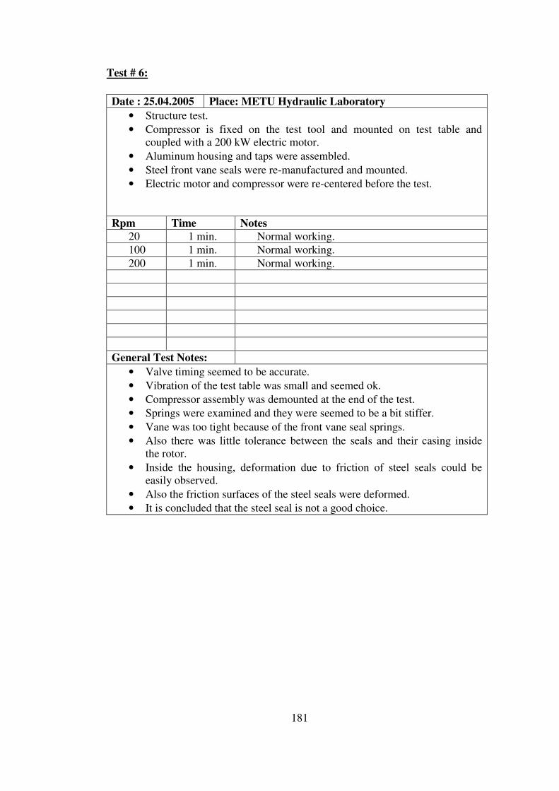
181
Test # 6:
Date : 25.04.2005 Place: METU Hydraulic Laboratory
• Structure test.
• Compressor is fixed on the test tool and mounted on test table and
coupled with a 200 kW electric motor.
• Aluminum housing and taps were assembled.
• Steel front vane seals were re-manufactured and mounted.
• Electric motor and compressor were re-centered before the test.
Rpm Time Notes 20 1 min. Normal working.
100 1 min. Normal working.
200 1 min. Normal working.
General Test Notes:
• Valve timing seemed to be accurate.
• Vibration of the test table was small and seemed ok.
• Compressor assembly was demounted at the end of the test.
• Springs were examined and they were seemed to be a bit stiffer.
• Vane was too tight because of the front vane seal springs.
• Also there was little tolerance between the seals and their casing inside
the rotor.
• Inside the housing, deformation due to friction of steel seals could be
easily observed.
• Also the friction surfaces of the steel seals were deformed.
• It is concluded that the steel seal is not a good choice.

182
Test # 7:
Date : 02.05.2005 Place: METU Hydraulic Laboratory
• Structure test.
• Compressor is fixed on the test tool and mounted on test table and
coupled with a 200 kW electric motor.
• Aluminum housing and taps were assembled.
• Steel front vane seals were mounted.
• Gray cast iron rotor top seals were mounted.
• Electric motor and compressor were re-centered before the test.
Rpm Time Notes
20 1 min. Normal working.
100 1 min. Normal working.
200 1 min. Normal working.
400 1 min. Normal working. Slight temp rise.
General Test Notes:
• Valve timing seemed to be accurate.
• Vibration of the test table was small and seemed ok.
• Compressor assembly was demounted at the end of the test.
• Vane was too tight because of the front vane seal springs.
• Also there was little tolerance between the seals and their casing inside
the rotor.
• Inside the housing, deformation due to friction of steel seals could be
easily observed.
• Also the friction surfaces of the steel seals were deformed.
• Top rotor seals were tight fit in their casings inside the rotor. Also because
of their springs stiffness they were exerting too much force on the taps.
• But the good news is that there were no deformation between the taps and
seals on the friction surfaces. The seal material (gray cast iron) seemed to
be well performing.

183
Test # 8:
Date : 09.05.2005 Place: METU Hydraulic Laboratory
• Structure test.
• Compressor is fixed on the test tool and mounted on test table and
coupled with a 200 kW electric motor.
• Steel housing and taps were assembled.
• Steel front vane seals were mounted.
• Electric motor and compressor were re-centered before the test.
Rpm Time Notes
20 1 min. Normal working.
100 1 min. Normal working.
200 1 min. Normal working.
400 1 min. Normal working. Slight temp rise.
General Test Notes:
• Valve timing seemed to be accurate.
• Vibration of the test table was small and seemed ok.
• Compressor assembly was demounted at the end of the test.
• Vane was too tight because of the front vane seal springs.
• Also there was little tolerance between the seals and their casing inside
the rotor.
• Inside the housing, deformation due to friction of steel seals could be
easily observed. This time the deformation was a bit less compared to
aluminum housing.
• Also the friction surfaces of the steel seals were deformed. This time the
deformation was more as steel housing was used.

184
Test # 9:
Date : 12.05.2005 Place: METU Hydraulic Laboratory
• Structure test.
• Compressor is fixed on the test tool and mounted on test table and
coupled with a 200 kW electric motor.
• Steel housing and taps were assembled.
• Steel front vane seals were mounted.
• Gray cast iron rotor top seals were mounted.
• Electric motor and compressor were re-centered before the test.
Rpm Time Notes
20 1 min. Normal working.
100 1 min. Normal working.
200 1 min. Normal working.
400 3 min. Normal working. Slight temp rise.
600 3 min. Normal working. Slight temp rise.
General Test Notes:
• Valve timing seemed to be accurate.
• Vibration of the test table was small and seemed ok.
• Compressor assembly was demounted at the end of the test.
• Vane was too tight because of the front vane seal springs.
• Also there was little tolerance between the seals and their casing inside
the rotor.
• Inside the housing, deformation due to friction of steel seals could be
easily observed. This time the deformation was a bit less compared to
aluminum housing.
• Also the friction surfaces of the steel seals were deformed. This time the
deformation was more as steel housing was used.
• Top rotor seals were tight fit in their casings inside the rotor. Also because
of their springs stiffness they were exerting too much force on the taps.
• But the good news is that there were no deformation between the taps and
seals on the friction surfaces. The seal material (gray cast iron) seemed to
be well performing.
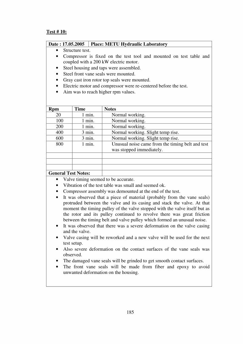
185
Test # 10:
Date : 17.05.2005 Place: METU Hydraulic Laboratory
• Structure test.
• Compressor is fixed on the test tool and mounted on test table and
coupled with a 200 kW electric motor.
• Steel housing and taps were assembled.
• Steel front vane seals were mounted.
• Gray cast iron rotor top seals were mounted.
• Electric motor and compressor were re-centered before the test.
• Aim was to reach higher rpm values.
Rpm Time Notes
20 1 min. Normal working.
100 1 min. Normal working.
200 1 min. Normal working.
400 3 min. Normal working. Slight temp rise.
600 3 min. Normal working. Slight temp rise.
800 1 min. Unusual noise came from the timing belt and test
was stopped immediately.
General Test Notes:
• Valve timing seemed to be accurate.
• Vibration of the test table was small and seemed ok.
• Compressor assembly was demounted at the end of the test.
• It was observed that a piece of material (probably from the vane seals)
protruded between the valve and its casing and stack the valve. At that
moment the timing pulley of the valve stopped with the valve itself but as
the rotor and its pulley continued to revolve there was great friction
between the timing belt and valve pulley which formed an unusual noise.
• It was observed that there was a severe deformation on the valve casing
and the valve.
• Valve casing will be reworked and a new valve will be used for the next
test setup.
• Also severe deformation on the contact surfaces of the vane seals was
observed.
• The damaged vane seals will be grinded to get smooth contact surfaces.
• The front vane seals will be made from fiber and epoxy to avoid
unwanted deformation on the housing.
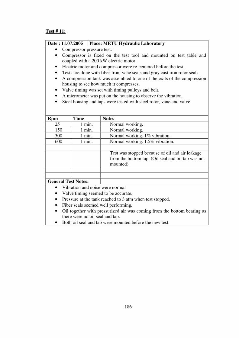
186
Test # 11:
Date : 11.07.2005 Place: METU Hydraulic Laboratory
• Compressor pressure test.
• Compressor is fixed on the test tool and mounted on test table and
coupled with a 200 kW electric motor.
• Electric motor and compressor were re-centered before the test.
• Tests are done with fiber front vane seals and gray cast iron rotor seals.
• A compression tank was assembled to one of the exits of the compression
housing to see how much it compresses.
• Valve timing was set with timing pulleys and belt.
• A micrometer was put on the housing to observe the vibration.
• Steel housing and taps were tested with steel rotor, vane and valve.
Rpm Time Notes
25 1 min. Normal working.
150 1 min. Normal working.
300 1 min. Normal working. 1% vibration.
600 1 min. Normal working. 1.5% vibration.
Test was stopped because of oil and air leakage
from the bottom tap. (Oil seal and oil tap was not
mounted)
General Test Notes:
• Vibration and noise were normal
• Valve timing seemed to be accurate.
• Pressure at the tank reached to 3 atm when test stopped.
• Fiber seals seemed well performing.
• Oil together with pressurized air was coming from the bottom bearing as
there were no oil seal and tap.
• Both oil seal and tap were mounted before the new test.
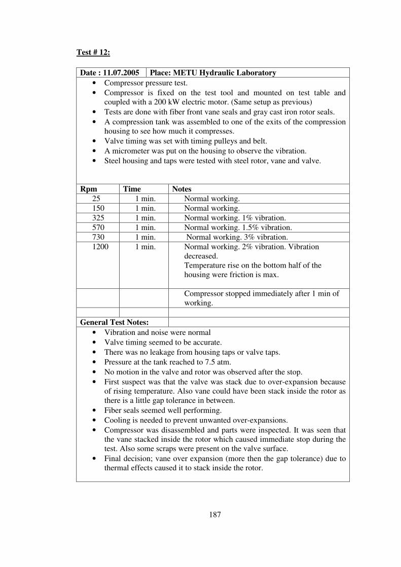
187
Test # 12:
Date : 11.07.2005 Place: METU Hydraulic Laboratory
• Compressor pressure test.
• Compressor is fixed on the test tool and mounted on test table and
coupled with a 200 kW electric motor. (Same setup as previous)
• Tests are done with fiber front vane seals and gray cast iron rotor seals.
• A compression tank was assembled to one of the exits of the compression
housing to see how much it compresses.
• Valve timing was set with timing pulleys and belt.
• A micrometer was put on the housing to observe the vibration.
• Steel housing and taps were tested with steel rotor, vane and valve.
Rpm Time Notes
25 1 min. Normal working.
150 1 min. Normal working.
325 1 min. Normal working. 1% vibration.
570 1 min. Normal working. 1.5% vibration.
730 1 min. Normal working. 3% vibration.
1200 1 min. Normal working. 2% vibration. Vibration
decreased.
Temperature rise on the bottom half of the
housing were friction is max.
Compressor stopped immediately after 1 min of
working.
General Test Notes:
• Vibration and noise were normal
• Valve timing seemed to be accurate.
• There was no leakage from housing taps or valve taps.
• Pressure at the tank reached to 7.5 atm.
• No motion in the valve and rotor was observed after the stop.
• First suspect was that the valve was stack due to over-expansion because
of rising temperature. Also vane could have been stack inside the rotor as
there is a little gap tolerance in between.
• Fiber seals seemed well performing.
• Cooling is needed to prevent unwanted over-expansions.
• Compressor was disassembled and parts were inspected. It was seen that
the vane stacked inside the rotor which caused immediate stop during the
test. Also some scraps were present on the valve surface.
• Final decision; vane over expansion (more then the gap tolerance) due to
thermal effects caused it to stack inside the rotor.
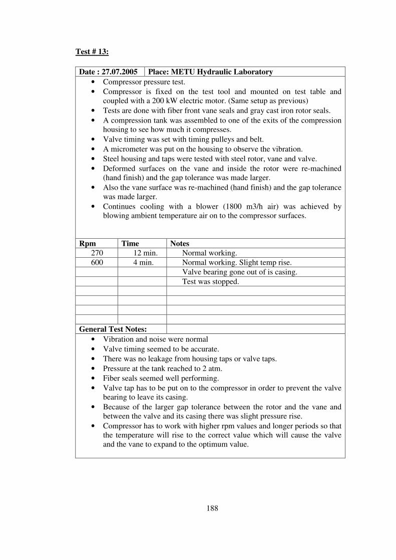
188
Test # 13:
Date : 27.07.2005 Place: METU Hydraulic Laboratory
• Compressor pressure test.
• Compressor is fixed on the test tool and mounted on test table and
coupled with a 200 kW electric motor. (Same setup as previous)
• Tests are done with fiber front vane seals and gray cast iron rotor seals.
• A compression tank was assembled to one of the exits of the compression
housing to see how much it compresses.
• Valve timing was set with timing pulleys and belt.
• A micrometer was put on the housing to observe the vibration.
• Steel housing and taps were tested with steel rotor, vane and valve.
• Deformed surfaces on the vane and inside the rotor were re-machined
(hand finish) and the gap tolerance was made larger.
• Also the vane surface was re-machined (hand finish) and the gap tolerance
was made larger.
• Continues cooling with a blower (1800 m3/h air) was achieved by
blowing ambient temperature air on to the compressor surfaces.
Rpm Time Notes
270 12 min. Normal working.
600 4 min. Normal working. Slight temp rise.
Valve bearing gone out of is casing.
Test was stopped.
General Test Notes:
• Vibration and noise were normal
• Valve timing seemed to be accurate.
• There was no leakage from housing taps or valve taps.
• Pressure at the tank reached to 2 atm.
• Fiber seals seemed well performing.
• Valve tap has to be put on to the compressor in order to prevent the valve
bearing to leave its casing.
• Because of the larger gap tolerance between the rotor and the vane and
between the valve and its casing there was slight pressure rise.
• Compressor has to work with higher rpm values and longer periods so that
the temperature will rise to the correct value which will cause the valve
and the vane to expand to the optimum value.
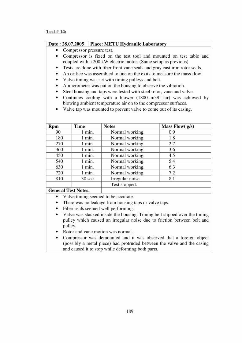
189
Test # 14:
Date : 28.07.2005 Place: METU Hydraulic Laboratory
• Compressor pressure test.
• Compressor is fixed on the test tool and mounted on test table and
coupled with a 200 kW electric motor. (Same setup as previous)
• Tests are done with fiber front vane seals and gray cast iron rotor seals.
• An orifice was assembled to one on the exits to measure the mass flow.
• Valve timing was set with timing pulleys and belt.
• A micrometer was put on the housing to observe the vibration.
• Steel housing and taps were tested with steel rotor, vane and valve.
• Continues cooling with a blower (1800 m3/h air) was achieved by
blowing ambient temperature air on to the compressor surfaces.
• Valve tap was mounted to prevent valve to come out of its casing.
Rpm Time Notes Mass Flow( g/s)
90 1 min. Normal working. 0.9
180 1 min. Normal working. 1.8
270 1 min. Normal working. 2.7
360 1 min. Normal working. 3.6
450 1 min. Normal working. 4.5
540 1 min. Normal working. 5.4
630 1 min. Normal working. 6.3
720 1 min. Normal working. 7.2
810 30 sec Irregular noise. 8.1
Test stopped.
General Test Notes:
• Valve timing seemed to be accurate.
• There was no leakage from housing taps or valve taps.
• Fiber seals seemed well performing.
• Valve was stacked inside the housing. Timing belt slipped over the timing
pulley which caused an irregular noise due to friction between belt and
pulley.
• Rotor and vane motion was normal.
• Compressor was demounted and it was observed that a foreign object
(possibly a metal piece) had protruded between the valve and the casing
and caused it to stop while deforming both parts.

190
Test # 15:
Date : 28.07.2005 Place: METU Hydraulic Laboratory
• Compressor high rpm endurance test.
• Compressor was fixed on the test tool and mounted on test table and
coupled with a 200kW electric motor. (Same setup as previous)
• Tests were done with fiber front vane seals and gray cast iron rotor seals.
• Valve timing was set with timing pulleys and belt.
• A micrometer was put on the housing to observe the vibration.
• Steel housing and taps were tested with steel rotor, vane and valve.
• Continues cooling with a blower (1800 m3/h air) was achieved by
blowing ambient temperature air on to the compressor surfaces.
Rpm Time Notes 100 30 sec Normal working.
200 30 sec Normal working.
300 30 sec Normal working.
500 1 min Normal working.
750 1 min. Normal working.
1000 1 min. Normal working.
1200 1 min. Normal working.
1500 1 min. Normal working.
1950 30 sec Immediate stop
Test stopped.
General Test Notes:
• Vibration and noise were normal during test.
• Temperature increased slightly during the test. (Not more then 60o C)
• Compressor was demounted and it was observed that vane was stacked
inside the rotor. Also slight deformation on the vane tips was observed
showing that the tips were touching the housing surface.
• Bolts joining the electric motor and the speed increaser gear box were
ruptured as the vane stacked and flew off around.

191
Test # 16:
Date : 28.07.2005 Place: METU Hydraulic Laboratory
• Compressor high rpm endurance test.
• Compressor was fixed on the test tool and mounted on test table and
coupled with a 200kW electric motor. (Same setup as previous)
• Tests were done with fiber front vane seals and gray cast iron rotor seals.
• Valve timing was set with timing pulleys and belt.
• A micrometer was put on the housing to observe the vibration.
• Steel housing and taps were tested with steel rotor, vane and valve.
• The gap tolerance between the rotor and the vane is made larger to avoid
stacking of vane.
• Continues cooling with a blower (1800 m3/h air) was achieved by
blowing ambient temperature air on to the compressor surfaces.
Rpm Time Notes 250 30 sec Normal working.
500 30 sec Normal working.
750 30 sec Normal working.
1000 1 min Normal working.
1250 1 min. Normal working.
1500 1 min. Normal working.
2000 1 min. Normal working.
2500 1 min. Normal working.
3100 30 sec Immediate stop
Test stopped.
General Test Notes:
• Max rpm reached with this prototype.
• Vibration and noise were normal during test.
• Temperature increased too much during the test.
• Compressor was demounted and it was observed that vane was stacked
inside the rotor.
• Bolts joining the electric motor and the speed increaser gear box were
ruptured as the vane stacked and flew off around.
• It is concluded that the cooling is insufficient for the ground tests. Due to
large temperature rise, unwanted over expansions could not be avoided.

192
Rotary Compressor Map
Mass Flow Rate vs RPM
0
2
4
6
8
10
12
14
16
18
20
0 250 500 750 1000 1250 1500 1750 2000 2250
m (g/s
)
RPM
Figure 4-1 Compressor Mass Flow Rate versus Rpm Chart
Volumetric Efficiency vs RPM
0
10
20
30
40
50
60
70
80
90
100
0 250 500 750 1000 1250 1500 1750 2000 2250
RPM
Vef
f.
Figure 4-2 Compressor Volumetric Eff. versus Rpm Chart
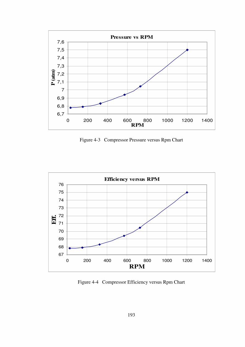
193
Pressure vs RPM
6,7
6,8
6,9
7
7,1
7,2
7,3
7,4
7,5
7,6
0 200 400 600 800 1000 1200 1400
RPM
P (atm
)
Figure 4-3 Compressor Pressure versus Rpm Chart
Efficiency versus RPM
67
68
69
70
71
72
73
74
75
76
0 200 400 600 800 1000 1200 1400
RPM
Eff
.
Figure 4-4 Compressor Efficiency versus Rpm Chart
194
4.2 Combustion Tests
Test # 1:
Date : 07.07.2005 Place: METU Hydraulic Laboratory
• Combustion chamber test.
• Combustion chamber was fixed on the test table.
• Pressurized air was being given from a compressor to the chamber inlet.
• Lpg tank was used as fuel supply and lpg was given into the inlet pipe of
the chamber.
• Continuous ignition was used.
• No valves were used at the inlet and exit of the housing.
• No cooling was used.
Rpm Time Notes
General Test Notes:
• Discontinuous combustion was achieved.
• Both pressurized air flow and fuel flow were regulated separately which
changed combustion timing.
195
Test # 2:
Date : 11.07.2005 Place: METU Hydraulic Laboratory
• Combustion chamber test.
• Combustion chamber was fixed on the test table.
• Pressurized air was being given from a compressor to the housing inlet.
• Lpg tank was used as fuel supply and lpg was given directly into the
chamber.
• Continuous ignition was used.
• No valves were used at the inlet and the exit of the chamber.
• No cooling was used.
Rpm Time Notes
General Test Notes:
• Continuous combustion was achieved.
• Both pressurized air flow and fuel flow were regulated separately which
changed combustion timing.
• At a proper mixing of air and fuel continuous combustion was achieved.
• Combustion chamber was teared off during the test due to over heating.

196
4.3 Turbine Tests
Test # 1:
Date : 24.05.2005 Place: METU Hydraulic Laboratory
• Turbine structure test.
• Turbine is fixed on the test tool and mounted on test table and coupled
with a 200kW electric motor.
• Steel housing and taps were assembled.
• Steel front vane seals were mounted.
• Gray cast iron rotor top seals were mounted.
• Electric motor and turbine were re-centered before the test.
• Aim was to revolve the turbine by giving pressurized air from the exit.
Air Pres. Time Notes
2 atm 1 min. No motion.
3 atm 1 min. No motion.
4 atm 1 min. No motion.
5 atm 3 min. No motion.
General Test Notes:
• It was seen that the front vane seals and top rotor seals were too tight in
their casings and their springs are stiffer then needed. Because of this the
turbine could not revolve with pressurized air.
• The front vane seals will be made from epoxy and fiber with a bigger
tolerance with their casings.
• The springs behind the vane seals will be made less stiff.
• The rotor top seals will be grinded on their top surfaces so that together
with their spring they won’t exert too much force on the taps.
• The springs under the top rotor seals will be made less stiff.
• Used steel vane seals will be grinded to smooth their deformed surfaces
with a bigger tolerance wrt their casing.
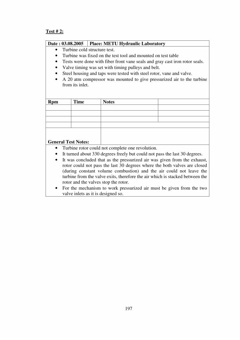
197
Test # 2:
Date : 03.08.2005 Place: METU Hydraulic Laboratory
• Turbine cold structure test.
• Turbine was fixed on the test tool and mounted on test table
• Tests were done with fiber front vane seals and gray cast iron rotor seals.
• Valve timing was set with timing pulleys and belt.
• Steel housing and taps were tested with steel rotor, vane and valve.
• A 20 atm compressor was mounted to give pressurized air to the turbine
from its inlet.
Rpm Time Notes
General Test Notes:
• Turbine rotor could not complete one revolution.
• It turned about 330 degrees freely but could not pass the last 30 degrees.
• It was concluded that as the pressurized air was given from the exhaust,
rotor could not pass the last 30 degrees where the both valves are closed
(during constant volume combustion) and the air could not leave the
turbine from the valve exits, therefore the air which is stacked between the
rotor and the valves stop the rotor.
• For the mechanism to work pressurized air must be given from the two
valve inlets as it is designed so.

198
Test # 3:
Date : 04.08.2005 Place: METU Hydraulic Laboratory
• Turbine cold structure test.
• Turbine was fixed on the test tool and mounted on test table
• Tests were done with fiber front vane seals and gray cast iron rotor seals.
• Valve timing was set with timing pulleys and belt.
• Steel housing and taps were tested with steel rotor, vane and valve.
• A 20 atm and a 10 atm compressor were mounted to give pressurized air
to the turbine from its inlet.
Pressure Rpm Mass Flow 2.0 atm 300
2.5 atm 400
General Test Notes:
• Turbine rotated easily as the air valve is opened.
• Two different compressors were feeding the two turbine valves with 2.5
atm pressurized air. Each of them can be adjusted separately.
• To give the same amount of pressurized air to both valves, they must be
fed with one single compressor so that it could reflect the true engine
operating condition.
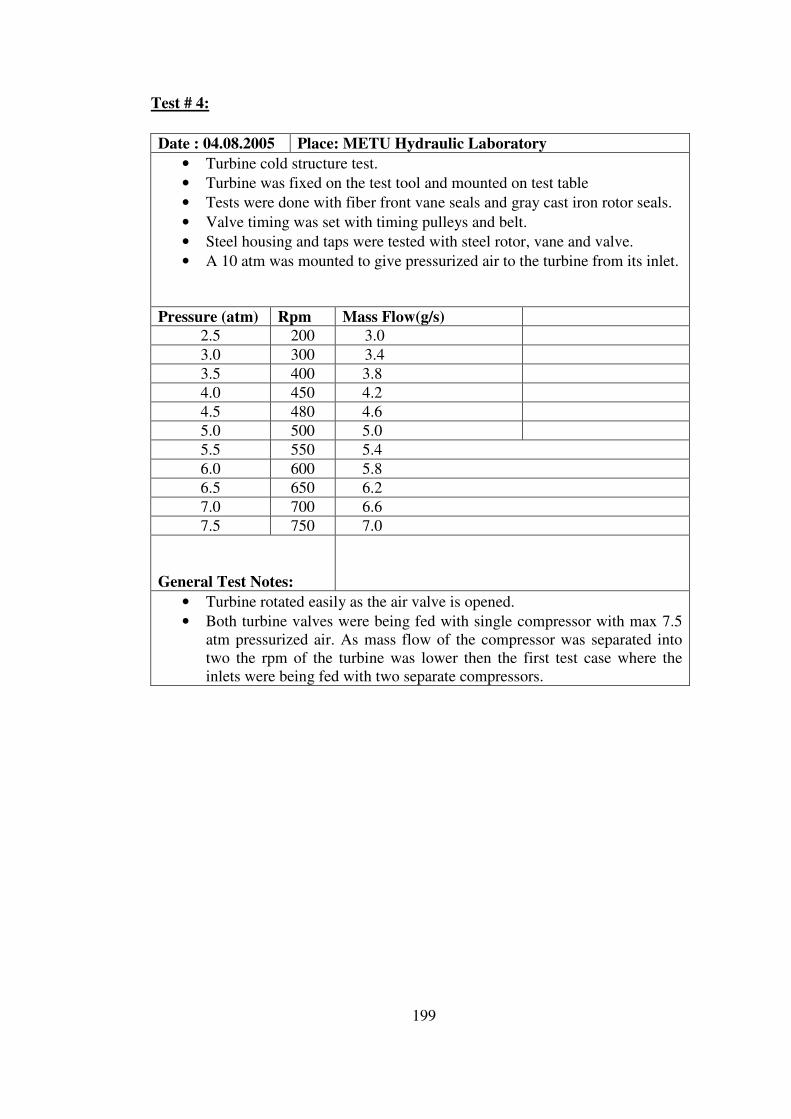
199
Test # 4:
Date : 04.08.2005 Place: METU Hydraulic Laboratory
• Turbine cold structure test.
• Turbine was fixed on the test tool and mounted on test table
• Tests were done with fiber front vane seals and gray cast iron rotor seals.
• Valve timing was set with timing pulleys and belt.
• Steel housing and taps were tested with steel rotor, vane and valve.
• A 10 atm was mounted to give pressurized air to the turbine from its inlet.
Pressure (atm) Rpm Mass Flow(g/s) 2.5 200 3.0
3.0 300 3.4
3.5 400 3.8
4.0 450 4.2
4.5 480 4.6
5.0 500 5.0
5.5 550 5.4
6.0 600 5.8
6.5 650 6.2
7.0 700 6.6
7.5 750 7.0
General Test Notes:
• Turbine rotated easily as the air valve is opened.
• Both turbine valves were being fed with single compressor with max 7.5
atm pressurized air. As mass flow of the compressor was separated into
two the rpm of the turbine was lower then the first test case where the
inlets were being fed with two separate compressors.

200
Rotary Turbine Map
RPM vs Mass Flow Rate
0
100
200
300
400
500
600
700
800
0 1 2 3 4 5 6 7 8m (g/s)
RP
M
Figure 4-5 Turbine Rpm versus Mass Flow Rate Chart
RPM vs Pressure
0
100
200
300
400
500
600
700
800
0 1 2 3 4 5 6 7 8
P (atm)
RP
M
Figure 4-6 Turbine Rpm versus Pressure Chart

201
Mass Flow Rate vs Pressure
0
1
2
3
4
5
6
7
8
0 1 2 3 4 5 6 7 8P (atm)
m (g/s
)
Figure 4-7 Turbine Mass Flow Rate versus Pressure Chart
202
Test Results
• Design rpm could not be reached during compressor tests due to structural
problems. Compressor vane stacked in the rotor due to overexpansion.
Efficient cooling is needed during ground tests.
• 7.5 atm is reached by the rotary compressor at 1200 rpm.
Sealing is over safe and must be reconsidered to decrease the wear friction
and the power extracted by the compressor. (That excess wear friction is also
responsible for vane overexpansion)
• Over 80% of volumetric efficiency was achieved by the compressor.
• During cold turbine tests, the compressor was not capable of discharging the
necessary pressurized air. Therefore, the rotary turbine speed could not
exceed 1000 rpm.
More powerful compressor is needed to discharge the necessary pressurized
the air that will simulate the combustion gases.
Sealing is over safe and must be reconsidered to decrease the wear friction
and increase power delivered by the turbine.
• Vibration was not much, through out the compressor and turbine tests
although, compression and turbine were unbalanced.
• Valve timing was accurate.
• Cooling system must be revised for the ground test.
• A more equipped data acquisition system must be used during the tests.

203
CHAPTER 5
CONCLUSION
5.1 Summary of Work
The work that has been done through out this thesis is summarized as
follows;
• Thermodynamic analysis of the novel rotary engine working on a novel
thermodynamic cycle has been done. A thermodynamic design code has been
written to dimension the novel rotary engine. The rotary compressor and the
rotary turbine of the engine have been matched and the geometric dimensions
of the engine components (rotary compressor, rotary turbine, external
combustion chamber) have been calculated according to the requirements of
an UAV designed and manufactured by TAI on which the designed novel
rotary engine is planned to be installed.
• Structural and mechanical design of the components of the novel rotary
engine has been done according to the geometric data taken from the
thermodynamic design code. All the components of the novel rotary engine
have been modeled and assembled in CAD environment (Unigraphics NX2)
and the required technical drawings of the components for the prototype
manufacturing have been prepared. A structural analysis of the critical
components have been carried out to define the manufacturing tolerances and
to select the material of the prototype using a finite element software.
(ANSYS 9.0) A prototype of the designed novel rotary engine has been
manufactured in the machining facility of TAI.
204
• The designed components of the novel rotary engine have been manufactured
in the 3-Axis NC Machining Center, 3-Axis Conventional Machining Center,
Conventional Milling and Lathe Centers. The assembly of the manufactured
components and the overhaul engine assembly have been done in the tooling
facility of TAI.
• The component tests of the manufactured prototype of the designed novel
rotary engine have been done in the Propulsion Laboratory of the Aerospace
Engineering Department of METU. Rotary compressor and turbine pressure,
temperature, mass flow, rpm, vibration, noise and endurance tests,
combustion tests, auxiliary systems (fuel, ignition, lubrication, cooling) tests
have been carried out.
• The performance parameters of the components of the designed novel rotary
engine have been determined using the component test data taken through out
the tests. The rotary compressor and rotary turbine maps have been plotted
using the test data. Material behavior of the manufactured prototype of the
designed novel rotary engine has been examined.

205
5.2 Recommendations for Future Work
A new prototype of the novel rotary engine should be designed, manufactured
and tested taking into account the design and manufacturing experience gained
through out this thesis.
The thermodynamic design code should be improved taking into account the
losses due to the un-isentropic compression and expansion phases, combustion
phase, mixing of compressed air with the remaining combustion gases in the
combustion chamber.
Material selection of the rotary compressor, turbine and the combustion
chamber should be revised. The selected rotary compressor material seemed well but
care should be taken when selecting the turbine material taking into account the high
temperature load on the components. Especially the seal and the spring material that
will be used in the turbine should be carefully inspected. As the material of the
combustion chamber is chosen to be a hot work tool steel, it seemed well but should
be revised taking into account weight considerations.
Structural analysis of the critical components of the novel rotary engine should
be revised using the real temperature and pressure data taken through out the tests.
The design of the prototype novel rotary engine should be changed to
overcome some manufacturing difficulties. Especially the geometry of the
compressor and turbine vanes and the discharge ports of the compressor are worth
reconsidering.
Cooling of the engine components should be studied. Especially, the rotor,
vane and valve of the rotary compressor must be cooled efficiently.
Balancing study should be done to balance the rotary compressor and turbine
in order to overcome vibrations and the unwanted effects of the vibrations.
More equipped data acquisition system should be used to make the prototype
engine tests so that the performance parameters of the engine could be easily
monitored. Also with the help of a PLC, the engine could be controlled by processing
the required engine data taken during the run.
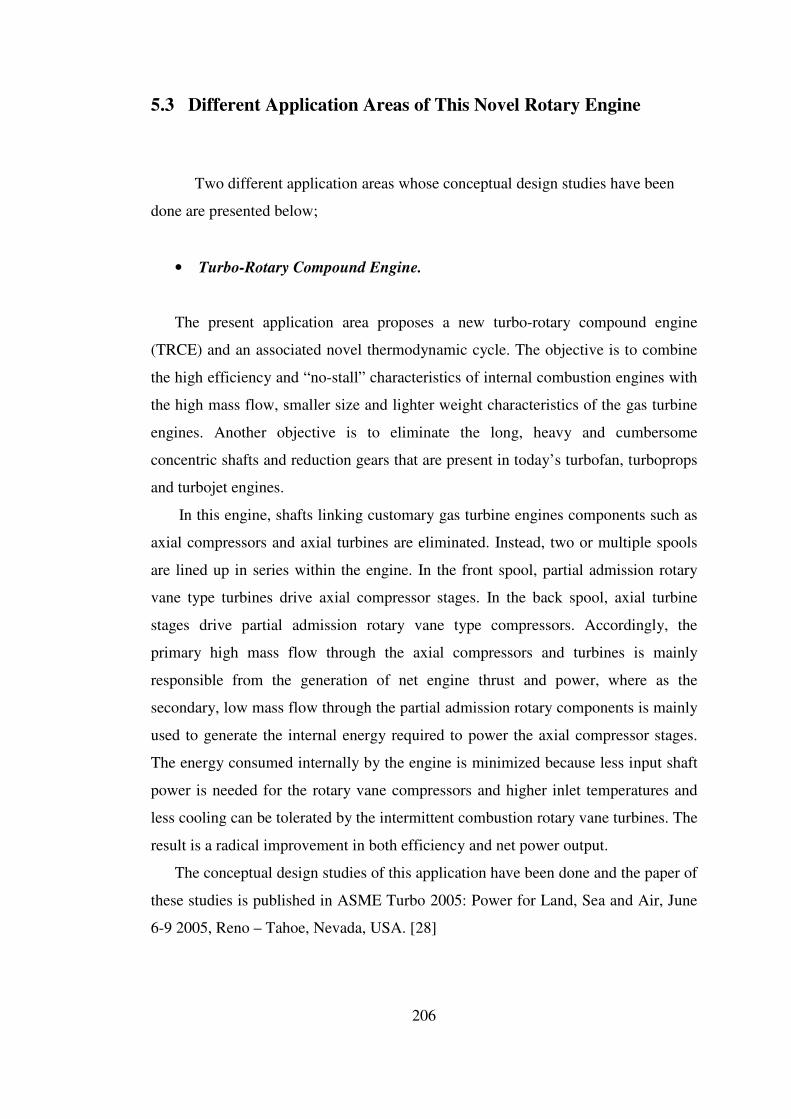
206
5.3 Different Application Areas of This Novel Rotary Engine
Two different application areas whose conceptual design studies have been
done are presented below;
• Turbo-Rotary Compound Engine.
The present application area proposes a new turbo-rotary compound engine
(TRCE) and an associated novel thermodynamic cycle. The objective is to combine
the high efficiency and “no-stall” characteristics of internal combustion engines with
the high mass flow, smaller size and lighter weight characteristics of the gas turbine
engines. Another objective is to eliminate the long, heavy and cumbersome
concentric shafts and reduction gears that are present in today’s turbofan, turboprops
and turbojet engines.
In this engine, shafts linking customary gas turbine engines components such as
axial compressors and axial turbines are eliminated. Instead, two or multiple spools
are lined up in series within the engine. In the front spool, partial admission rotary
vane type turbines drive axial compressor stages. In the back spool, axial turbine
stages drive partial admission rotary vane type compressors. Accordingly, the
primary high mass flow through the axial compressors and turbines is mainly
responsible from the generation of net engine thrust and power, where as the
secondary, low mass flow through the partial admission rotary components is mainly
used to generate the internal energy required to power the axial compressor stages.
The energy consumed internally by the engine is minimized because less input shaft
power is needed for the rotary vane compressors and higher inlet temperatures and
less cooling can be tolerated by the intermittent combustion rotary vane turbines. The
result is a radical improvement in both efficiency and net power output.
The conceptual design studies of this application have been done and the paper of
these studies is published in ASME Turbo 2005: Power for Land, Sea and Air, June
6-9 2005, Reno – Tahoe, Nevada, USA. [28]
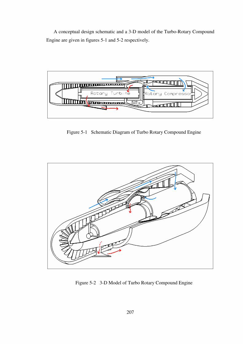
207
A conceptual design schematic and a 3-D model of the Turbo-Rotary Compound
Engine are given in figures 5-1 and 5-2 respectively.
Figure 5-1 Schematic Diagram of Turbo Rotary Compound Engine
Figure 5-2 3-D Model of Turbo Rotary Compound Engine

208
• Micro Vehicle Propulsion
Micro air vehicles are small (not larger then 20 cm) unmanned air
vehicles, whose mission is surveillance without being detected. In today’s
Micro Air Vehicles (MAV), photovoltaic, battery, thermo-electric and
internal combustion engines are being used. But today’s micro internal
combustion engines (0.67 hp/lb) have very low efficiency and thus 10 – 20
times more specific fuel consumption then 4 stroke ICE.
The conceptual design study of a micro version of this novel rotary
engine has been done and a presentation is done in the Tokyo University, July
2004. The geometry of the micro rotary engine is calculated using the
thermodynamic design code and three micro rotary engines having 300W,
30W and 3W shaft power have been designed.
The novel micro rotary engine, with its efficient compression done in
closed volume, steady operation, large torque and good cooling capacity, and
two power strokes per one rpm, is a good alternative to power the micro air
vehicles. A preliminary design model of a micro rotary engine is given in
figure 5-3.
Figure 5-3 Micro Rotary Engine
209
REFERENCES
1. Smith D.G. and Rudge, P.G., “Pressure-Volume Diagrams for Sliding Vane
Rotary Compressors”, Proc. Instn. Mech. Engineers, Vol.184 Pt3R, Paper 17,
(1970), 159-166.
2. Chou, Y., “Rotary Vane Engine”, USPTO 5,352,295, (October 4th
1994).
3. Vading, K., “Rotary-Piston Machine”, PCT WO 02/31318, (April 18th
2002).
4. Umeda, S., “Rotary Internal Combustion Engine”, USPTO 4,414,938,
(November 15th
1983).
5. LAI, J.H., “Stage Combustion Rotary Engine”, USPTO 5,596,963, (January
28th
1997).
6. Jirnov, A., and Jirnov, O., “Sliding-Blade Heat Engine with Vortex
Combustion Chamber”, USPTO5, 511,525, (April 30th
1996).
7. Cummins, Jr., C.L.: “Internal Fire, Carnot Press, Lake Oswego, Oreg.,
1976.
8. Cummins, Jr.,C.L.: “Early IC and Automotive Engines” SAE paper 760604
in A History of the Automotive Internal Combustion Engine, SP-409, SAE
Trans., vol.85, 1976.
9. Hempson, J.G.G.: “The Automobile Engine 1920 – 1950,” SAE paper
760605 in A History of the Automotive Internal Combustion Engine, SP-409,
SAE, 1976.
10. Agnew, W.G.: “Fifty Years of Combustion Research at General Motors,”
Progress in Energy and Combustion Science, vol 4, pp. 115-156, 1978.
11. Wankel, F.: Rotary Piston Machines, Iliffe Books, London, 1965.
12. Ansade,R.F.: The Wankel RC Engine Design and Performance, Iliffe Books,
London, 1968.
13. Yamamoto, K.: Rotary Engine, Toyo Kogyo Co. Ltd., Hiroshima, 1969.
14. Obert, E. F.: Internal Combustion Engine, 1950.

210
15. Taylor C. F. and Taylor E. S.: The Internal Combustion Engine 1984.
16. Heywood,J. B.: Internal Combustion Engine Fundamentals, 1988.
17. Akmandor, İ.S., Ersöz, N.: Novel Thermodynamic Cycle, PTC / WO /
2004 / 022919 AI. (March 18th
2004)
18. Chou, Y., “Rotary Vane Engine”, USPTO 5,352,295, (October 4th
1994).
19. Vading, K., “Rotary-Piston Machine”, PCT WO 02/31318, (April 18th
2002).
20. Umeda, S., “Rotary Internal Combustion Engine”, USPTO 4,414,938,
(November 15th
1983).
21. LAI, J.H., “Stage Combustion Rotary Engine”, USPTO 5,596,963, (January
28th
1997).
22. Jirnov, A., and Jirnov, O., “Sliding-Blade Heat Engine with Vortex
Combustion Chamber”, USPTO5, 511,525, (April 30th
1996).
23. Akmandor, İ.S., Ercan T., Karaca M., Aran G., “New Engine and
Thermodynamic Cycle of Tusas Aerospace Industries (TAI) Unmanned Air
Vehicle”, International Symposium on Innovative Aerial/Space Flyer
Systems, Tokyo – Japan, December 10-11 2004
24. Zabanski J.S. and Voevodin A.A., “Advanced Hard Coatings and Wear
Resistant Materials for Aerospace”, AGARD-CP-589, May 6-7 1996
25. Clouser S.D. and Kamin R.A., “Combustion Technology Needs For
Advanced High Pressure Cycle Engines”, AGARD-CP-536, May 10th
1993
26. Jacobson Bo, “Thin Film Lubrication of Non-Smooth Surfaces”, AGARD-
CP-589, May 6-7 1996
27. Woydt M., “Tribological Assessments and Concepts for an Oilfree Internal
Combustion Engine”, AGARD-CP-589, May 6-7 1996
28. Akmandor, İ.S., Ercan T., Karaca M., “Turbo-Rotary Compound Engine
and Novel Thermodynamic Cycle”, GT2005-68234, Paper accepted for
ASME Turbo-Expo 2005, Nevada USA, June 6-9 2005
211
APPENDIX A
DIFFERENT CONFIGURATIONS OF THE NOVEL ROTARY ENGINE
1st Side By Side Configuration (Without External Combustion Chamber)
• In this configuration, the compressor and the turbine assemblies are placed
side by side.
• The compressor and the turbine assemblies are coupled with each other by
the help of a gear box, in which three gears are beared.
• There is no external combustion chamber in between the compressor and the
turbine. The compressed air passes directly to the turbine and combustion
takes place within the turbine. (Internal combustion engine)
• Passing of compressed air from compressor to turbine is achieved by a rotary
valve placed in between.
• Valve is directly coupled with the compressor rotor and timing is achieved by
valve timing coupling.
• A water jacket surrounds the compressor and turbine assembly for cooling
purposes.
• Cold water is also circulated on the upper and lower taps of the turbine
assembly.
• A 3-D Cad model of the whole configuration and a 2-D Cad model of the
compressor and the turbine are given in figures A-1 and A-2 respectively.
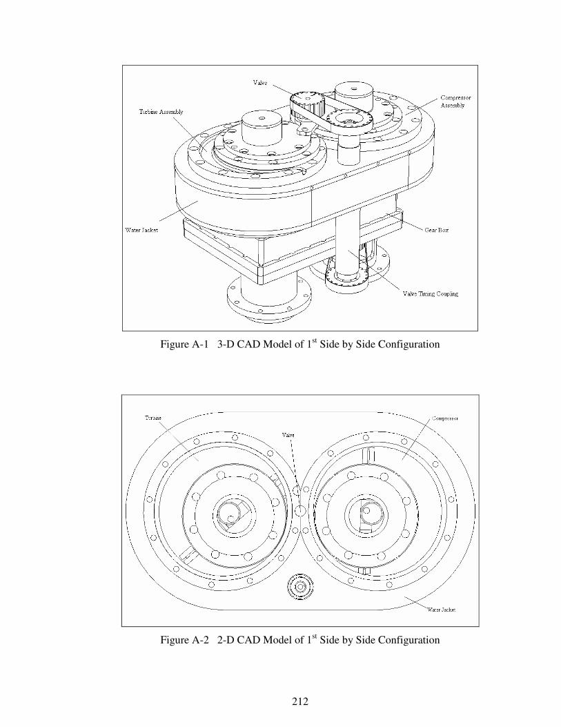
212
Figure A-1 3-D CAD Model of 1st Side by Side Configuration
Figure A-2 2-D CAD Model of 1st Side by Side Configuration

213
2nd
Side By Side Configuration (With External Combustion Chamber)
• In this configuration, the compressor and the turbine assemblies are placed
side by side.
• The compressor and the turbine assemblies are coupled with each other by
the help of a gear box, in which three gears are beared.
• There is an external combustion chamber in between the compressor and the
turbine. The compressed air passes to the combustion chamber where it is
mixed with fuel and combustion takes place within the chamber. (External
combustion engine)
• After combustion, the combustion gases pass through the turbine where they
expand.
• There is a rotating vane placed within the combustion chamber two divide the
chamber into two to achieve two ignitions per one revolution.
• Vane of the combustion chamber is directly coupled with the compressor
rotor and timing is achieved by vave timing coupling.
• A water jacket surrounds the compressor and turbine assembly for cooling
purposes.
• Cold water is also circulated on the upper and lower taps of the turbine
assembly.
• A 3-D Cad model of the whole configuration and a 2-D Cad model of the
compressor and the turbine are given in figures A-3 and A-4 respectively.
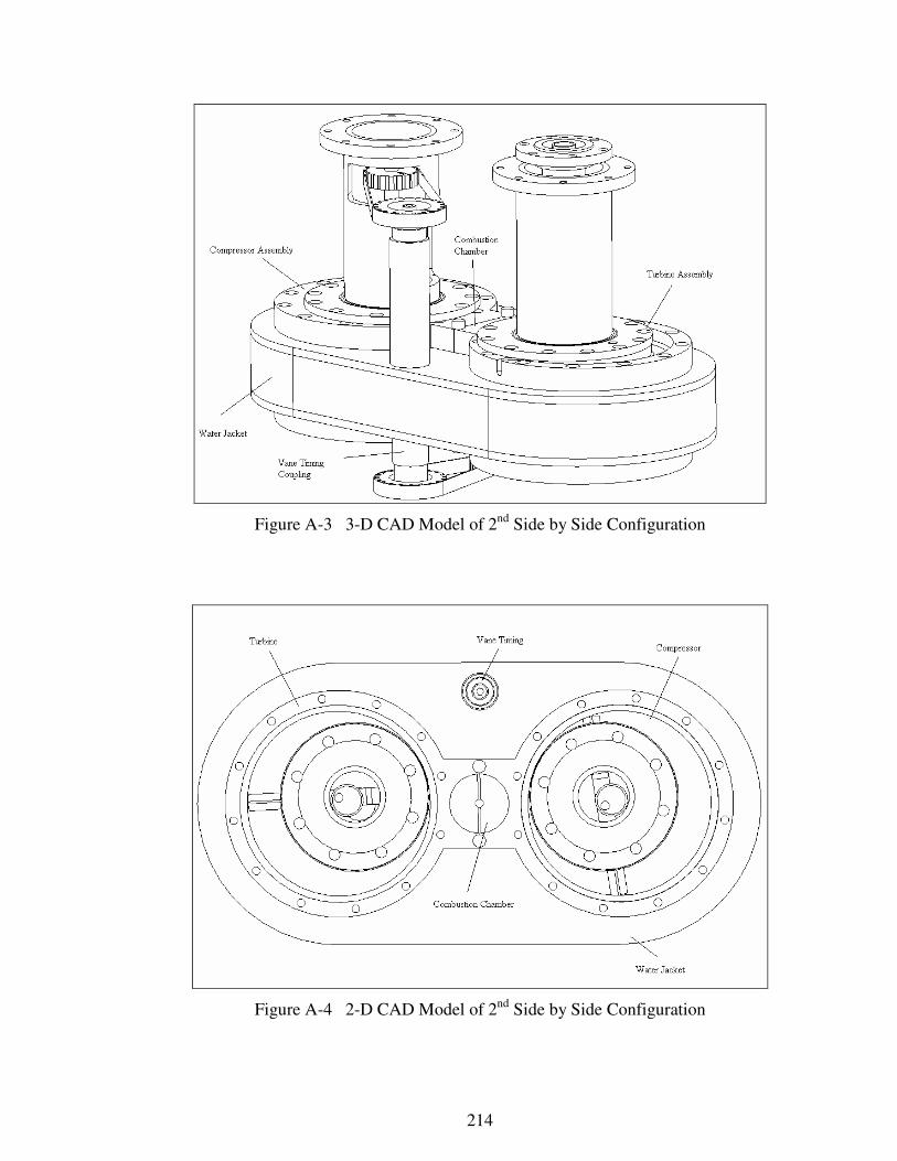
214
Figure A-3 3-D CAD Model of 2nd
Side by Side Configuration
Figure A-4 2-D CAD Model of 2nd
Side by Side Configuration

215
APPENDIX B
VANE TIP ANALYSIS
Objective of the vane tip analysis is;
• To analyze the interaction of the vane tip with the housing inner surface.
• To define tip clearances.
• To define vane tip geometry
The analytical geometry of the vane is given below;
Figure B-1 Analytical Vane Tip Geometry

216
The vane tip clearance (TCL) formulation is given below;
( )
−−
−−=
−− )).2.cos(..2(3602
1
)).2.cos(..2(3603602
1
3602
1tan.2..cos..2.tan.cos).2..cos..2(2/1
ππ θ
π
θ
π θθa
h
a
h
CLaaaaT
(B.1)
where,
θ (vane angle) 0 – 360 degrees
h (vane halfthickness) 6 mm
a (eccentricity) 15 mm
l (vane length) 140 mm
By changing θ (vane angle) from 0 degrees to 360 degress, the max contact
tolerance between the vane tip and the housing inner surface due to the thickness of
the vane is calculated using the vane tip clearance formulation. The maximum in
contact distance is calculated as 1.301 mm where the vane angle (θ) is 75 degrees. At
that angle, the vane and the housing are modeled and the vane tip geometry is
determined.
After modeling the tip geometry, the kinematical motion assembly of the
rotary compressor is done and the tip clearances are checked at different vane angles.
Results showed that the designed vane tip geometry fits the housing inner surface at
every vane angle. The vane tip contact analysis of the compressor is given in the
following figure B-2.

217
Figure B-2 Vane Tip Contact Analysis
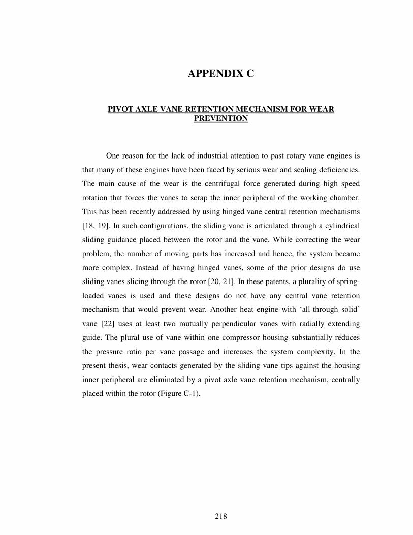
218
APPENDIX C
PIVOT AXLE VANE RETENTION MECHANISM FOR WEAR
PREVENTION
One reason for the lack of industrial attention to past rotary vane engines is
that many of these engines have been faced by serious wear and sealing deficiencies.
The main cause of the wear is the centrifugal force generated during high speed
rotation that forces the vanes to scrap the inner peripheral of the working chamber.
This has been recently addressed by using hinged vane central retention mechanisms
[18, 19]. In such configurations, the sliding vane is articulated through a cylindrical
sliding guidance placed between the rotor and the vane. While correcting the wear
problem, the number of moving parts has increased and hence, the system became
more complex. Instead of having hinged vanes, some of the prior designs do use
sliding vanes slicing through the rotor [20, 21]. In these patents, a plurality of spring-
loaded vanes is used and these designs do not have any central vane retention
mechanism that would prevent wear. Another heat engine with ‘all-through solid’
vane [22] uses at least two mutually perpendicular vanes with radially extending
guide. The plural use of vane within one compressor housing substantially reduces
the pressure ratio per vane passage and increases the system complexity. In the
present thesis, wear contacts generated by the sliding vane tips against the housing
inner peripheral are eliminated by a pivot axle vane retention mechanism, centrally
placed within the rotor (Figure C-1).
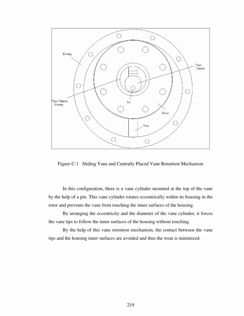
219
Figure C-1 Sliding Vane and Centrally Placed Vane Retention Mechanism
In this configuration, there is a vane cylinder mounted at the top of the vane
by the help of a pin. This vane cylinder rotates eccentrically within its housing in the
rotor and prevents the vane from touching the inner surfaces of the housing.
By arranging the eccentricity and the diameter of the vane cylinder, it forces
the vane tips to follow the inner surfaces of the housing without touching.
By the help of this vane retention mechanism, the contact between the vane
tips and the housing inner surfaces are avoided and thus the wear is minimized.
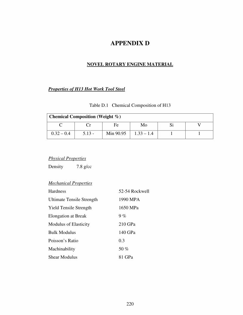
220
APPENDIX D
NOVEL ROTARY ENGINE MATERIAL
Properties of H13 Hot Work Tool Steel
Table D.1 Chemical Composition of H13
Chemical Composition (Weight %)
C Cr Fe Mo Si V
0.32 – 0.4 5.13 - Min 90.95 1.33 – 1.4 1 1
Physical Properties
Density 7.8 g/cc
Mechanical Properties
Hardness 52-54 Rockwell
Ultimate Tensile Strength 1990 MPA
Yield Tensile Strength 1650 MPa
Elongation at Break 9 %
Modulus of Elasticity 210 GPa
Bulk Modulus 140 GPa
Poisson’s Ratio 0.3
Machinability 50 %
Shear Modulus 81 GPa
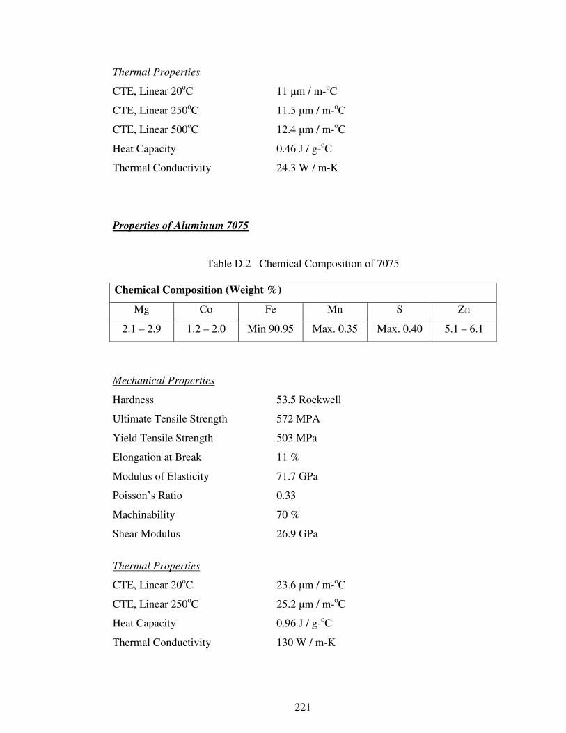
221
Thermal Properties
CTE, Linear 20oC 11 µm / m-
oC
CTE, Linear 250oC 11.5 µm / m-
oC
CTE, Linear 500oC 12.4 µm / m-
oC
Heat Capacity 0.46 J / g-oC
Thermal Conductivity 24.3 W / m-K
Properties of Aluminum 7075
Table D.2 Chemical Composition of 7075
Chemical Composition (Weight %)
Mg Co Fe Mn S Zn
2.1 – 2.9 1.2 – 2.0 Min 90.95 Max. 0.35 Max. 0.40 5.1 – 6.1
Mechanical Properties
Hardness 53.5 Rockwell
Ultimate Tensile Strength 572 MPA
Yield Tensile Strength 503 MPa
Elongation at Break 11 %
Modulus of Elasticity 71.7 GPa
Poisson’s Ratio 0.33
Machinability 70 %
Shear Modulus 26.9 GPa
Thermal Properties
CTE, Linear 20oC 23.6 µm / m-
oC
CTE, Linear 250oC 25.2 µm / m-
oC
Heat Capacity 0.96 J / g-oC
Thermal Conductivity 130 W / m-K
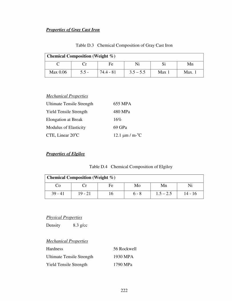
222
Properties of Gray Cast Iron
Table D.3 Chemical Composition of Gray Cast Iron
Chemical Composition (Weight %)
C Cr Fe Ni Si Mn
Max 0.06 5.5 - 74.4 - 81 3.5 – 5.5 Max 1 Max. 1
Mechanical Properties
Ultimate Tensile Strength 655 MPA
Yield Tensile Strength 480 MPa
Elongation at Break 16%
Modulus of Elasticity 69 GPa
CTE, Linear 20oC 12.1 µm / m-
oC
Properties of Elgiloy
Table D.4 Chemical Composition of Elgiloy
Chemical Composition (Weight %)
Co Cr Fe Mo Mn Ni
39 - 41 19 - 21 16 6 - 8 1.5 – 2.5 14 - 16
Physical Properties
Density 8.3 g/cc
Mechanical Properties
Hardness 56 Rockwell
Ultimate Tensile Strength 1930 MPA
Yield Tensile Strength 1790 MPa
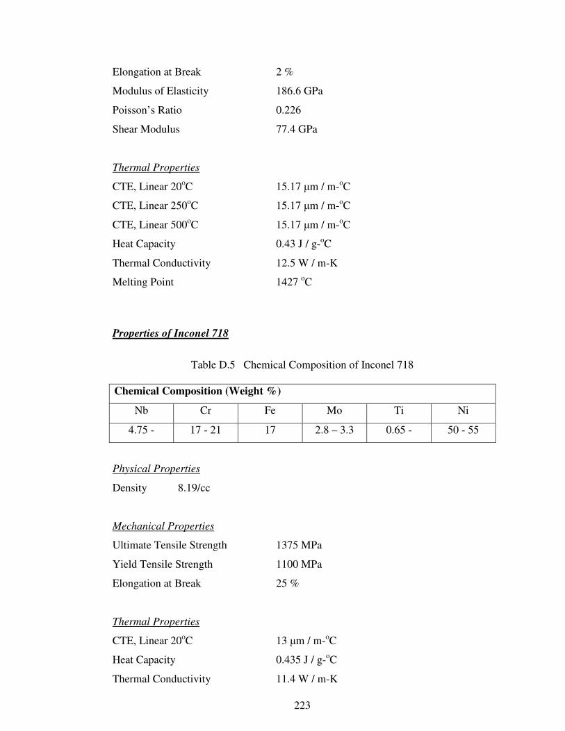
223
Elongation at Break 2 %
Modulus of Elasticity 186.6 GPa
Poisson’s Ratio 0.226
Shear Modulus 77.4 GPa
Thermal Properties
CTE, Linear 20oC 15.17 µm / m-
oC
CTE, Linear 250oC 15.17 µm / m-
oC
CTE, Linear 500oC 15.17 µm / m-
oC
Heat Capacity 0.43 J / g-oC
Thermal Conductivity 12.5 W / m-K
Melting Point 1427 oC
Properties of Inconel 718
Table D.5 Chemical Composition of Inconel 718
Chemical Composition (Weight %)
Nb Cr Fe Mo Ti Ni
4.75 - 17 - 21 17 2.8 – 3.3 0.65 - 50 - 55
Physical Properties
Density 8.19/cc
Mechanical Properties
Ultimate Tensile Strength 1375 MPa
Yield Tensile Strength 1100 MPa
Elongation at Break 25 %
Thermal Properties
CTE, Linear 20oC 13 µm / m-
oC
Heat Capacity 0.435 J / g-oC
Thermal Conductivity 11.4 W / m-K

224
Properties of Pyrowear Alloy 53 Tool Steel
Table D.6 Chemical Composition of Pyrowear Alloy 53
Chemical Composition (Weight %)
C Cr Fe Ni Si Mo
0.1 1 90 2 1 3.25
Physical Properties
Density 7.8 g/cc
Mechanical Properties
Ultimate Tensile Strength 1207 MPA
Yield Tensile Strength 896 MPa
Elongation at Break 12%
Thermal Properties
CTE, Linear 20oC 11.26 µm / m-
oC
CTE, Linear 250oC 12.06 µm / m-
oC
CTE, Linear 500oC 13.05 µm / m-
oC
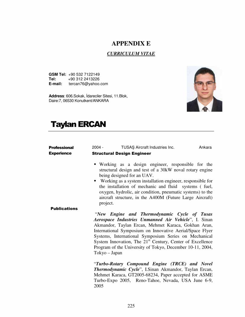
225
APPENDIX E
CURRICULUM VITAE
Taylan ERCAN
Professional
Experience
Publications
2004 - TUSAŞ Aircraft Industries Inc. Ankara
Structural Design Engineer
� Working as a design engineer, responsible for the
structural design and test of a 30kW noval rotary engine
being designed for an UAV.
� Working as a system installation engineer, responsible for
the installation of mechanic and fluid systems ( fuel,
oxygen, hydrolic, air condition, pneumatic systems) to the
aircraft structure, in the A400M (Future Large Aircraft)
project.
“New Engine and Thermodynamic Cycle of Tusas
Aerospace Industries Unmanned Air Vehicle”, I. Sinan
Akmandor, Taylan Ercan, Mehmet Karaca, Gokhan Aran,
International Symposium on Innovative Aerial/Space Flyer
Systems, International Symposium Series on Mechanical
System Innovation, The 21st Century, Center of Excellence
Program of the University of Tokyo, December 10-11, 2004,
Tokyo – Japan
“Turbo-Rotary Compound Engine (TRCE) and Novel
Thermodynamic Cycle”, I.Sinan Akmandor, Taylan Ercan,
Mehmet Karaca, GT2005-68234, Paper accepted for ASME
Turbo-Expo 2005, Reno-Tahoe, Nevada, USA June 6-9,
2005
GSM Tel: +90 532 7122149 Tel: +90 312 2413226 E-mail: [email protected]
Address: 606.Sokak, İdareciler Sitesi, 11.Blok, Daire:7, 06530 Konutkent/ANKARA

226
2002 - 2003 TUSAŞ Engine Industries Inc. Eskişehir
Product Development Engineer
� Took ANSYS Introduction 1-2 & Advanced (Material
Nonlinearities, Contact, Transient Analyses) Training,
November ~ December 2002 (6 Weeks).
� Took FLUENT Introduction and Advanced Training,
January 2003 (3 Weeks).
� Worked as a design engineer, responsible for the structural
design and analyze of a novel turbo engine.
2000 - 2001 Bosporus Software Inc. Ankara
Cad – Cam – Cae Consultant
� Gave Basic and Advanced Cad education to the Product Development Department of Bosch, Manisa. Consulted in the water heater optimisation project.
� Gave Advanced Cad education to the Product Development Department of ARÇELİK, Bolu. Consulted in the oven front panel design, printer and plotter management.
� Gave Basic Cad education to Cad – Cam Center of BİLTİR, METU.
� Gave Basic Cad–Cam education to the Design Department of Erkunt Casting Inc., Ankara.
� Consulted in Valysis (CMM software developed by Technomatics, USA) education and installation to the CMM Department of TAI (Tusaş Aircraft Industries Inc.). Also participated in the Information Management System upgrade process using IMAN software.
� Gave Cae education to the Analysis Department of 2. Air Supply and Maintenance Centre, Kayseri. Consulted in Finite Element Methodology for the analysis of wings and fuselage.
� Consulted in the different Cad–Cam projects of the customers such as PI Machinery Inc., Ankara, HAS-IZ Mold, Ankara, 1. Air Supply and Maintenance Centre, Eskişehir.
Summer Practice
Summer, 1997 Koruma A.Ş. Kocaeli
� Management practice for 6 weeks.
Summer, 1996 2. Air Supply and Maintenance Centre Kayseri
� Manufacturing practice for 6 weeks.
227
Education
2002 - 2005 Middle East Technical University Ankara
� M.Sc., Aeronautical Engineering.
Thesis Title: Thermodynamic and Structural Design and
Analysis of a Novel Turbo Rotary Engine.
1994–2001 Middle East Technical University Ankara
� B.Sc., Aeronautical Engineering.
1987-1994 F.M.V. Işık College İstanbul
Computer
Knowledge
Cad-Cam programs : Unigraphics, CATIA, I-DEAS, AutoCAD.
CAE programs : Ansys 9.0, Fluent 7.0, Gambit, TGrid
Programming Language : Fortran77, Visual Basic 6.0
Other : MathCAD 8.0, Win NT, 2000, MS – Office.
Language English: Very good command both written and spoken.
German: Good command both written and spoken.
Certificates ANSYS Basic and Advanced Training (FIGES), FLUENT Basic and Advanced Training (FIGES), Sales and Marketing Techniques (Yapı Kredi Yaşam A.Ş.,Ankara), English Translation (National Education Ministry), Valysis (3-D measurement device software, Technomatics, USA), FAI Micro-light Marshalling and Model Aircraft (THK) Certificates.
Community
Activities
Izmit Yachting Club and METU Aeronautical Club membership, making model aircraft and walking in nature, swimming and diving.
References
Available on request.