Thermocouple s
6
July 2003 1 Thermocouples by Greg Passler What is a thermocouple and how does it work? Why do we use thermocouples? What is thermocouple extension cable? These commonly asked questions about thermocouples exist due to the seemingly mysterious nature of these widely used temperature sensing devices. The discussion that follows will dispel some of that mystery and provide a fundamental un- derstanding of thermocouples. Table 1 compares the more common methods of temperature measurement against certain criteria. The devices range from the basic thermometer, which is a liquid expansion device, to more complex methods such as the use of a hand held infrared temperature sensing unit. Each device has applications for which its use is most appropriate, but thermocouples tend to be among the most popular, especially in industrial applications. Device Low Cost Passive Electric Signal Accurate Robust Wide Range Thermocouple √√ √ √ √ √ √ RTD √ √√ √ √ Infrared √ √ Bimetallic √ √ Liquid Expansion √ √ State Change √ √ Table 1 - Methods of Temperature Measurement There are several reasons for the popularity of thermocouples. Perhaps most importantly, they are relatively inexpensive and easy to make. They can be used over a large temperature range, from about -250°C up to about 1800°C. Although they aren’t the most accurate means of measuring temperature, they have plenty of accuracy for most applications, with only one or two degrees of error across their operating range. Thermocouples are also passive devices that produce an electric signal without having to be powered. Finally, they are very robust and durable, making them ideal for harsh indus- trial environments. To understand how thermocouples work, we should review some basic theory of operation. In 1821, a man by the name of Seebeck discovered the phenomena behind how thermocouples work and the principle was named the “Seebeck Effect”. It states that a voltage is produced as a result of heating one junction of a circuit formed with two dissimilar metal conductors. This principle is depicted graphically in its most simple form in Figure 1. Two wires are connected at each end to form a circuit. One wire is an alloy of copper, and the other is iron, which is what a J type thermocouple is made from. The ends of the circuit where the wires are joined are called “junctions”. If we apply heat to one of the junctions, called the “sensing junction”, a voltage is formed and current begins to flow through the circuit. At the other end of this circuit, called the “refer- ence junction”, a device is connected to measure the amount of voltage produced. The measured voltage allows us to infer the temperature at the hot, or sensing junction. The greater the temperature, the higher the voltage and vice versa. This is the basic theory behind how thermocouples operate. Figure 1 - The Seebeck Effect produces a voltage in thermocouple circuits.
-
Upload
marey-morsy -
Category
Documents
-
view
226 -
download
0
Transcript of Thermocouple s
July 2003 1
Thermocouplesby Greg Passler
What is a thermocouple and how does it work?Why do we use thermocouples?What is thermocouple extension cable?
These commonly asked questions about thermocouples exist due to the seemingly mysterious nature of these widely used temperature sensing devices. The discussion that follows will dispel some of that mystery and provide a fundamental un-derstanding of thermocouples.
Table 1 compares the more common methods of temperature measurement against certain criteria. The devices range from the basic thermometer, which is a liquid expansion device, to more complex methods such as the use of a hand held infrared temperature sensing unit. Each device has applications for which its use is most appropriate, but thermocouples tend to be among the most popular, especially in industrial applications.
Device Low Cost PassiveElectric Signal Accurate Robust
Wide Range
Thermocouple √√ √ √ √ √ √
RTD √ √√ √ √
Infrared √ √
Bimetallic √ √
Liquid Expansion √ √
State Change √ √
Table 1 - Methods of Temperature Measurement
There are several reasons for the popularity of thermocouples. Perhaps most importantly, they are relatively inexpensive and easy to make. They can be used over a large temperature range, from about -250°C up to about 1800°C. Although they aren’t the most accurate means of measuring temperature, they have plenty of accuracy for most applications, with only one or two degrees of error across their operating range. Thermocouples are also passive devices that produce an electric signal without having to be powered. Finally, they are very robust and durable, making them ideal for harsh indus-trial environments.
To understand how thermocouples work, we should review some basic theory of operation.
In 1821, a man by the name of Seebeck discovered the phenomena behind how thermocouples work and the principle was named the “Seebeck Effect”. It states that a voltage is produced as a result of heating one junction of a circuit formed with two dissimilar metal conductors.
This principle is depicted graphically in its most simple form in Figure 1. Two wires are connected at each end to form a circuit. One wire is an alloy of copper, and the other is iron, which is what a J type thermocouple is made from. The ends of the circuit where the wires are joined are called “junctions”. If we apply heat to one of the junctions, called the “sensing junction”, a voltage is formed and current begins to flow through the circuit. At the other end of this circuit, called the “refer-ence junction”, a device is connected to measure the amount of voltage produced. The measured voltage allows us to infer the temperature at the hot, or sensing junction. The greater the temperature, the higher the voltage and vice versa. This is the basic theory behind how thermocouples operate.
Figure 1 - The Seebeck Effect produces a voltage in thermocouple circuits.

July 2003 2
Scientists and researchers have developed complex mathematical expressions to describe the relationship between ther-mocouple voltage and temperature. Fortunately, these values are well established and are represented in Figure 2 for eight of the ANSI letter-designated thermocouple types. The voltages that are induced are very small and are typically less than 1/50th of one volt.
The slope of each line represents a particular thermo-couple’s “Seebeck Coeffi cient”. In general, the great-er the slope of the line or Seebeck Coeffi cient, the better, because the instrumentation that is required to measure the thermocouple voltage does not need to be as sensitive and there is less opportunity for error in the reading. Unfortunately, the thermocouples with the highest Seebeck Coeffi cients also have the low-est operating temperatures so we are forced to use other thermocouple types with low coeffi cients when measuring extremely high temperatures.
When selecting a thermocouple, there are several important elements to consider with respect to its operating environment. Temperature is probably an obvious aspect, but also, because of the presence of two dissimilar metals, corrosion is an important con-sideration. Some thermocouples can’t be exposed to a reducing environment (low oxygen, high carbon monoxide and hydrogen content), others to an oxidizing environment (oxygen and water vapour). Whether they will be exposed to vacuum or irradiation are also issues to consider.
The range of temperatures that the various thermocouple types can be used at are shown in Figure 3. Types T and E are preferred for low temperatures, while Types S, R and B are used for extremely high temperatures and use expensive alloys of platinum.
The most common types of thermocouples are J, K and T. Each have their own characteristics that make them most suitable for only certain applications. J is very versatile and low cost, but is also the least accurate. Type K is suitable for nuclear environments, but not in a vacuum or reducing environments. Type T is good for low tem-peratures and is highly corrosion resistant.
Type E has the highest Seebeck Coeffi cient and, similar to Type K, should not be used in vacuum or reducing atmospheres. Type N resists oxidation well and satisfi es a broad range of applications.
Types S, R and B are suitable for very high temperatures but are expensive due to the use of platinum.
Users of thermocouple wire should be aware of the various trade names that exist to describe each of the conductors. For example, “Constantan” is a Hoskins registered trade mark for the negative thermoelement, or conductor, used in Types E, J and T
thermocouple wire. This same wire is available from an-other manufacturer, Carpenter, as “Cupron”. The same type of situation exists for the positive thermoelements of Types E and K Thermocouples and the negative thermoel-ement of Type K thermocouples (refer to table 2).
Figure 3 - The allowable temperature range for 8 Thermocouple Types is shown here.
Thermoelement Carpenter HoskinsEN, JN, TN Cupron ConstantanEP, KP Tophel ChromelKN Nial AlumelNP Nicrosil NicrosilNN Nisil Nisil
Table 2 - Various tradenames exist for individual thermoelements
Figure 2 - The Seebeck Coeffi cients for various thermocouple types
July 2003 3
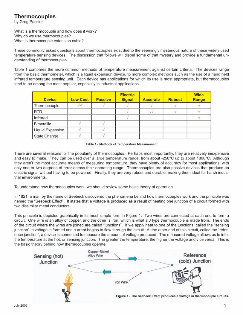
Figure 4 depicts a typical example of a thermocouple in use in an industrial application. Shown is a plastics extruder that is applying a jacket to an armoured cable as it passes through the cross head. The cross head has two thermocouples installed in it to measure and monitor the melt temperature of the plastic (note the arrows).
Most thermocouples have some form of mechanical protection, as shown in Figure 5. The tip of one of the thermocouples that has been pulled from the cross head is protected by a stainless steel sheath and the lead wires are armoured along their length also with stainless steel.
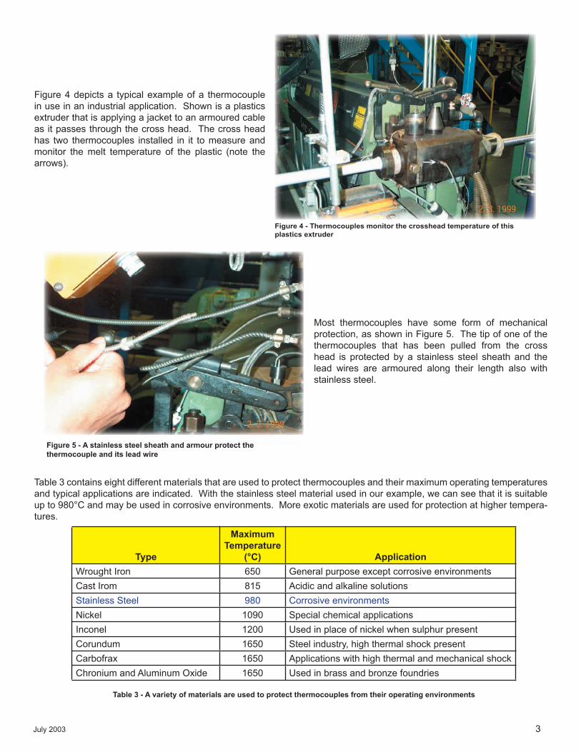
Table 3 contains eight different materials that are used to protect thermocouples and their maximum operating temperatures and typical applications are indicated. With the stainless steel material used in our example, we can see that it is suitable up to 980°C and may be used in corrosive environments. More exotic materials are used for protection at higher tempera-tures.
Figure 4 - Thermocouples monitor the crosshead temperature of this plastics extruder
Type
Maximum Temperature
(°C) ApplicationWrought Iron 650 General purpose except corrosive environmentsCast Irom 815 Acidic and alkaline solutionsStainless Steel 980 Corrosive environmentsNickel 1090 Special chemical applicationsInconel 1200 Used in place of nickel when sulphur presentCorundum 1650 Steel industry, high thermal shock presentCarbofrax 1650 Applications with high thermal and mechanical shockChronium and Aluminum Oxide 1650 Used in brass and bronze foundries
Table 3 - A variety of materials are used to protect thermocouples from their operating environments
Figure 5 - A stainless steel sheath and armour protect the thermocouple and its lead wireFigure 5 - A stainless steel sheath and armour protect the thermocouple and its lead wire

July 2003 4
The size of the thermocouple wire is also an important consideration. Usually the higher the operating tempera-ture, the bigger the gauge size to slow the effects of cor-rosion. Table 4 demonstrates an example of this concept. For a J thermocouple to operating at its highest rated tem-perature, it is recommended that an 8 AWG conductor be selected, whereas much small conductors can be used at lower temperatures.
The materials used to cover thermocouple wire are usually rated for high temperatures and include fluoropolymers, and glass and fibre braids. (see Figure 6).
In general, the materials used to insulate and jacket thermocouples are expensive relative to conventional wire and cable materials such as PVC and polyethylene. This is necessitated by their relatively high temperature ratings.
Another circuit diagram is shown in Figure 7 to demonstrate the use of thermocouple extension cable. Similar to before, thermocouple wire is used at the sensing junction, but this time, the thermocouple lead wires are connected to ther-mocouple extension wire which is connected to the monitoring device.
The reason we use thermocouple extension cable is to reduce costs on long cabling runs. Thermocouple extension cables, because they aren’t in contact with the temperature being measured (like the thermocouple itself), do not need to be de-signed for the same extremes in operating temperature. This equates to less expensive insulation and jacket materials. In addition, even though the extension cable uses the same metal as the thermocouple wire itself, the alloys are often a lower grade that only need to be accurate over a much smaller temperature range.
It should be pointed out that different metals altogether are used for Types S, B, and R extension wire due to the very high cost of the platinum used in these thermocouple types. The extension wire for these thermocouples have similar electro-thermic properties as the thermocouple itself, but over a more limited temperature range. This kind of cable is called a “compensating cable”.
Extension cable is differentiated from thermocouple cable through the use of a “X” suffix, for example “JX”. Compensating cable has a “C” suffix, for example “SC”.
ANSI Type J Thermocouple
Gauge (AWG)Maximum Operating
Temperature (°C)
814202428
760540480370370
Table 4 - Thermocouple wire size is often determined by the maxi-mum expected operating temperature
Thermocouple Insulation/Jackets
• Usually rated for high temperatures - Tefzel (150°C) - Teflon (205°C) - Kapton (316°C) - Glass Braid with Silicome (482°C) - Ceramic Fibre (1400°C)
• Expensive relative to conventional wire and cable materials
Figure 6 - High temperature materials are usually chosen for thermocouple coverings
Figure 7 - Thermocouple extension cable is used to reduce costs on long cabling runs.
July 2003 5
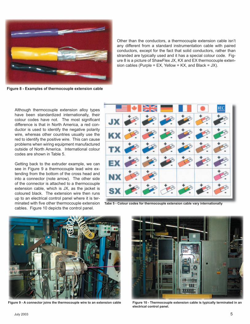
Other than the conductors, a thermocouple extension cable isn’t any different from a standard instrumentation cable with paired conductors, except for the fact that solid conductors, rather than stranded are typically used and it has a special colour code. Fig-ure 8 is a picture of ShawFlex JX, KX and EX thermocouple exten-sion cables (Purple = EX, Yellow = KX, and Black = JX).
Although thermocouple extension alloy types have been standardized internationally, their colour codes have not. The most signifi cant difference is that in North America, a red con-ductor is used to identify the negative polarity wire, whereas other countries usually use the red to identify the positive wire. This can cause problems when wiring equipment manufactured outside of North America. International colour codes are shown in Table 5.
Getting back to the extruder example, we can see in Figure 9 a thermocouple lead wire ex-tending from the bottom of the cross head and into a connector (note arrow). The other side of the connector is attached to a thermocouple extension cable, which is JX, as the jacket is coloured black. The extension wire then runs up to an electrical control panel where it is ter-minated with fi ve other thermocouple extension cables. Figure 10 depicts the control panel.
Figure 8 - Examples of thermocouple extension cable
Tabe 5 - Colour codes for thermocouple extension cable vary internationally
Figure 9 - A connector joins the thermocouple wire to an extension cable Figure 10 - Thermocouple extension cable is typically terminated in an electrical control panel.
July 2003 6
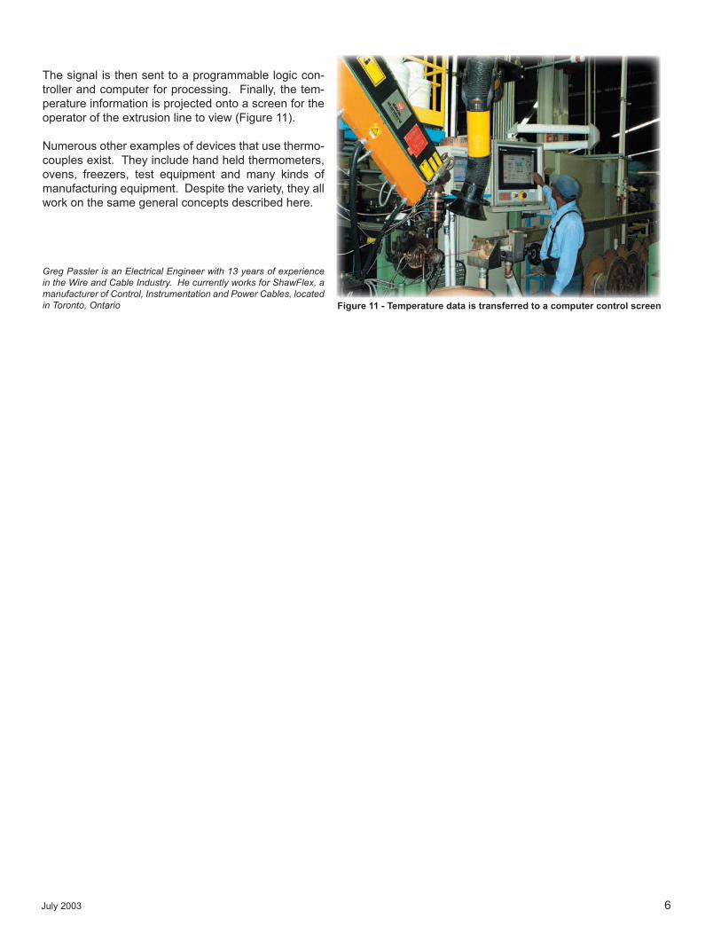
The signal is then sent to a programmable logic con-troller and computer for processing. Finally, the tem-perature information is projected onto a screen for the operator of the extrusion line to view (Figure 11).
Numerous other examples of devices that use thermo-couples exist. They include hand held thermometers, ovens, freezers, test equipment and many kinds of manufacturing equipment. Despite the variety, they all work on the same general concepts described here.
Greg Passler is an Electrical Engineer with 13 years of experience in the Wire and Cable Industry. He currently works for ShawFlex, a manufacturer of Control, Instrumentation and Power Cables, located in Toronto, Ontario Figure 11 - Temperature data is transferred to a computer control screen