Thermo Scientific APEX Metal Detector User’s Guide · Thermo Scientific APEX Metal Detector...
442
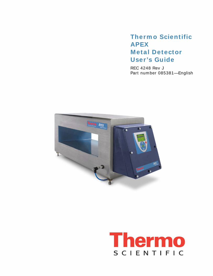
Thermo Scientific APEX Metal Detector User’s Guide REC 4248 Rev J Part number 085381—English
Transcript of Thermo Scientific APEX Metal Detector User’s Guide · Thermo Scientific APEX Metal Detector...
Thermo Scientific APEX Metal Detector User’s Guide REC 4248 Rev J Part number 085381—English
Page 2 Thermo Scientific APEX User’s Guide
© 2009 Thermo Fisher Scientific, Inc. All rights reserved For future reference, write your APEX serial number below. APEX serial # = __________________________________
Thermo Scientific APEX User’s Guide Page 3
Table of Contents
Getting Started ........................................................................... 11 Setting Global and Application-Specific Parameters .......................................... 11 Setting Product Parameters .......................................................................... 11 Managing Product-Rejection Parameters ........................................................ 12 Choosing Your Application Type .................................................................... 12
Setting Up Conveyor Applications ............................................... 13 Understanding Your Detector .......................................................... 14
Understanding the Detector’s Control Panel .................................................... 14 Using the Detector’s Buttons ........................................................................ 15 Understanding the Screen Shots Used in this Manual ....................................... 16 Understanding the Detector’s Main Menu ....................................................... 17 Choosing a Language .................................................................................. 17 Clearing the Speed-Filter Warning Screen ...................................................... 20 Displaying Help Text ................................................................................... 20 Choosing Your Preferred Units of Measure ...................................................... 22
Naming the Product ....................................................................... 24 Setting Up the Conveyor and Photo-Eye ........................................... 27
Keying In the Product Speed ........................................................................ 27 Keying In the Photo-Eye-to-Detector Distance ................................................ 28 Checking the Polarity of the Photo-Eye Input .................................................. 30 Selecting the Correct Photo Registration for Rejects ......................................... 32
Setting Product Parameters ............................................................ 35 Keying In the Pack Length ........................................................................... 35 Keying In the No-Pack Distance .................................................................... 37 Disabling the Detection No-Pack Function ....................................................... 38 Keying In the Pack Gap ............................................................................... 40
Setting Reject Parameters .............................................................. 43 Keying In the Distance to the Reject Device ................................................... 44 Keying In the Signal Duration for the Reject Device ......................................... 46
Setting Contaminant-Detection Parameters ...................................... 47 Establishing Noise Thresholds with No Product Present ..................................... 47 Calibrating the Speed Filter Using a Ferrous Test Stick ..................................... 50 Establishing Basic Product Parameters ........................................................... 52 Changing the Current Product ...................................................................... 60
Set-Up Check List for Conveyor Applications ..................................... 61 Parameters You Have Already Set Up ............................................................ 61 Additional Parameters You May Want to Set Up ............................................... 62
Setting Up Gravity-Feed Applications ......................................... 63 Setting Reject Parameters .............................................................. 65
Understanding Reject-Delay and Reject-Duration Timing .................................. 65 Setting the Reject-Delay Time ...................................................................... 66 Setting the Reject-Duration Time .................................................................. 67
Setting Contaminant-Detection Parameters ...................................... 69 Establishing a Baseline with No Product Present .............................................. 69 Calibrating the Speed Filter Using a Ferrous Test Ball ....................................... 72 Establishing Basic Product Parameters ........................................................... 73
Page 4 Thermo Scientific APEX User’s Guide
Set-Up Check List for Gravity-Feed Applications ................................ 76 Parameters You Have Already Set Up ............................................................. 76 Additional Parameters You May Want to Set Up ............................................... 77
Setting Up Pipeline Applications ................................................. 79 Setting Reject Parameters .............................................................. 81
Understanding Reject-Delay and Reject-Duration Timing ................................... 81 Setting the Reject-Delay Time ....................................................................... 82 Setting the Reject-Duration Time ................................................................... 83
Setting Contaminant-Detection Parameters ....................................... 85 Establishing a Baseline with No Product Present ............................................... 85 Choosing the Appropriate Wide-Band Speed Filter ............................................ 88 Establishing Basic Product Parameters ............................................................ 90
Set-Up Check List for Pipeline Applications ........................................ 93 Parameters You Have Already Set Up ............................................................. 93 Additional Parameters You May Want to Set Up ............................................... 94
Setting Up Pharmaceutical (Rx) Applications ............................. 95 Setting Reject Parameters .............................................................. 97
Understanding Reject-Delay and Reject-Duration Timing ................................... 97 Setting the Reject-Delay Time ....................................................................... 98 Setting the Reject-Duration Time ................................................................... 99
Setting Contaminant-Detection Parameters ..................................... 101 Establishing a Baseline with No Product Present ............................................. 101 Choosing the Correct Speed-Filter Settings for the Rx ..................................... 104 Establishing Basic Product Parameters .......................................................... 105
Set-Up Check List for Pharmaceutical Applications ........................... 108 Parameters You Have Already Set Up ........................................................... 108 Additional Parameters You May Want to Set Up ............................................. 109
APEX Menu Structure ................................................................ 111 Main Menu—Page 1 ..................................................................... 111
Product Name ........................................................................................... 111 Product Speed .......................................................................................... 111 Reject-Totals Menu .................................................................................... 112 Detect Level ............................................................................................. 113 Phase-Angle Menu ..................................................................................... 113 Peak Signal .............................................................................................. 114 Frequency and Gain Menu........................................................................... 114 System and Tools Menu.............................................................................. 115 Security Menu ........................................................................................... 115
Main Sub-Menu—Page 1 ............................................................... 115 Starting a Complete Product Calibration ........................................................ 116 Editing the Product Name ........................................................................... 116
Main Sub-Menu—Page 2 ............................................................... 116 Setting the Pack Length ............................................................................. 117 Setting the Pack Gap ................................................................................. 117 Setting the No-Pack Distance ...................................................................... 117
Rejects Menu—Page 1 .................................................................. 118 Resetting the Counts for Reject 1 ................................................................ 118 Setting the Distance to the Reject-1 Device ................................................... 119 Changing the Units of Measure .................................................................... 119

Thermo Scientific APEX User’s Guide Page 5
Setting the Signal Duration for the Reject-1 Device ........................................ 119 Displaying the Number of Quality Test Rejects ............................................... 120 Displaying the Number of AuditCheck Rejects ................................................ 120
Rejects Menu—Page 2 ................................................................. 121 Setting the Type of Photo Registration Used .................................................. 121 Setting the Latching-Reject Function (Reject 1) ............................................. 122 Inverting the Reject Function (Reject 1)........................................................ 123 Calibrating the Speed-Encoder Function ........................................................ 124 Understanding the Photo-Queue Pack Count .................................................. 127
Rejects Menu—Page 3 ................................................................. 128 Suppressing Rejection Using an External Trigger (Reject 1) ............................. 129 Activating Reject Suppression (Reject 1) ....................................................... 130 Understanding Reject Suppression (Reject 1) ................................................ 130 Activating Reject Suppression (Reject 1) ....................................................... 131 Setting Suppression Time (Reject 1) ............................................................ 132 Setting Amplitude Suppression (Reject 1) ..................................................... 134
Rejects Menu—Page 4 ................................................................. 136 Calibrating Reject-Confirm Times ................................................................. 137 Manually Setting the Timing for a Reject-1 Confirm ........................................ 138 Manually Setting the Timing for a Reject-1 Complete ...................................... 139
Rejects Menu—Page 5 ................................................................. 141 Keying In the Distance to the Reject-2 Device ............................................... 142 Keying In the Signal Duration for the Reject-2 Device ..................................... 142 Assigning Tasks to the Reject-2 Device ......................................................... 143 Setting the Latching-Reject Function for Reject 2 ........................................... 144 Inverting the Reject Function for Reject 2 ..................................................... 144
Rejects Menu—Page 6 ................................................................. 145 Entering a Reject-Confirm Time for the Reject-2 Device .................................. 145 Calibrating the Reject-2 Confirm Time .......................................................... 147
Phase Angle—Page 1 ................................................................... 150 Calibrating the Phase-Angle Setting ............................................................. 151 Locking the Phase-Angle Setting .................................................................. 152 Enabling the Detector’s Phase-Tracking Function ............................................ 153 Setting Acceptable Limits for Phase Tracking ................................................. 155 Setting Limits for a Phase-Tracking Fault Notification ...................................... 156
Phase Angle—Page 2 ................................................................... 157 Selecting the Wet-Product Noise Filter .......................................................... 157 Selecting the Phased-Noise Reduction Filter .................................................. 158 Selecting the Quadrature Noise-Reduction Filter ............................................. 159
Frequency and Gain—Page 1 ........................................................ 160 Setting High or Low Frequency .................................................................... 161 Setting High or Low Gain ............................................................................ 162 Inhibiting Detection ................................................................................... 162
Frequency and Gain—Page 2 ........................................................ 163 Calibrating the Detect Level ........................................................................ 163 Changing the Detect Level .......................................................................... 164 Setting Multi-Zone Detection ....................................................................... 165 Locking the Detect Level ............................................................................. 166 Calibrating the X and R Noise Thresholds ...................................................... 166 Changing the Noise Threshold for X .............................................................. 167 Changing the Noise Threshold for R .............................................................. 167
Page 6 Thermo Scientific APEX User’s Guide
System and Tools—Page 1 ........................................................... 168 Quality Test .............................................................................................. 168 AuditCheck ............................................................................................... 168 Error Messages (WAFs) .............................................................................. 169 Manual Print ............................................................................................. 169 Bar-Graph/Help-Text Set-Up for the Display Panel ......................................... 169 IntelliTrack (IXR) ....................................................................................... 169
System and Tools—Page 2 ........................................................... 170 Viewing Your Speed-Filter Settings ............................................................... 170 Inputs and Outputs Menu ........................................................................... 172 Copying and Pasting Product Parameters ...................................................... 173 Setting the Time and Date .......................................................................... 176 Setting Metric or Imperial Units ................................................................... 178
System and Tools—Page 3 ........................................................... 179 Setting the Photo-Eye-to-Detector Distance .................................................. 179 Setting Reject Duration (Time or Distance) for Your Reject Devices .................. 180 Setting the “Reject Packs During Learn” Function ........................................... 182 Resetting the Counts When Products Change ................................................. 183 Resetting Product Parameters to the Default Settings ..................................... 184 Resetting the NVRAM Parameters to the Default Settings ................................ 186 Oscilloscope .............................................................................................. 187
System and Tools—Page 4 ........................................................... 192 Selecting the Language for the Display Panel’s Help Text ................................ 192
System and Tools—Page 5 ........................................................... 193 Displaying Your Software Version ................................................................. 193 Displaying Your APEX Model Type ................................................................ 194 Displaying Your System Set-Up Code ........................................................... 194 Displaying Your Product Set-Up Code ........................................................... 195
Quality Test ................................................................................ 196 Overview of How the Quality Test Function Works .......................................... 197 Testing the Detector Using QA Test Samples ................................................. 198 Setting the Time Interval Between QA Tests .................................................. 200 Setting the Time Window for Doing a QA Test ................................................ 201 Setting the Reject Device Used for the QA Test .............................................. 202 Doing a Manual QA Test ............................................................................. 203 Setting Limits for Peak Signal and Phase Angle .............................................. 204
AuditCheck ................................................................................. 206 Performing an AuditCheck Test .................................................................... 207 Displaying the Average Phase Angle ............................................................. 208 Displaying the Average Peak Signal .............................................................. 208 Setting the Lock-Values Function ................................................................. 208 Setting Manual-Start, Timing-Limits, and Reject-Device Parameters ................. 209 Setting Limits for Peak Signal and Phase Angle .............................................. 210 Setting the AuditCheck Overhang Distance .................................................... 210 Setting the AuditCheck Pulse Length ............................................................ 211 Setting the AuditCheck Signal Time-Out ....................................................... 212
Error Messages (WAFs) ................................................................ 214 Defining Warnings, Alarms, and Faults (WAFs) .............................................. 214 WAFs Are Not Mutually Exclusive ................................................................. 215 Setting a WAF for a Particular Function ......................................................... 215 Learning About Other WAFs ........................................................................ 217
Thermo Scientific APEX User’s Guide Page 7
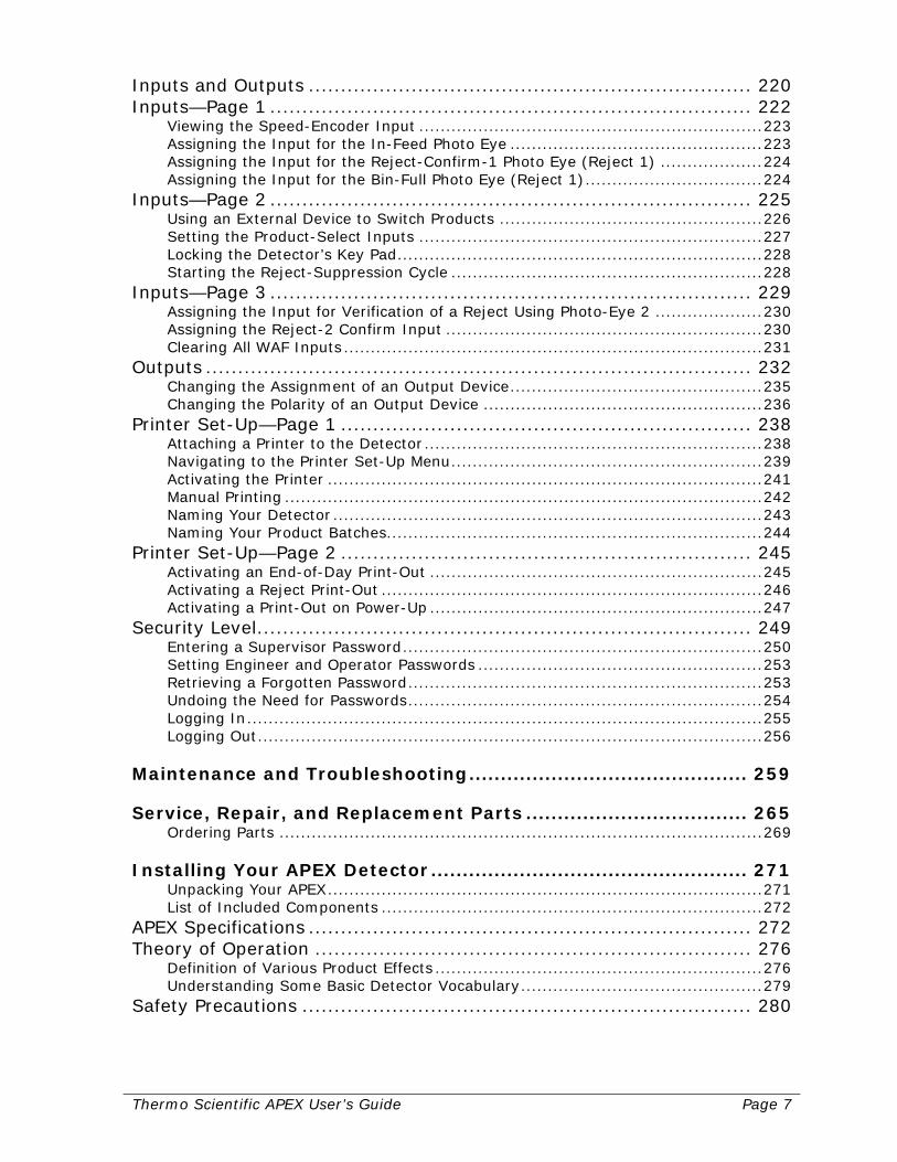
Inputs and Outputs ..................................................................... 220 Inputs—Page 1 ........................................................................... 222
Viewing the Speed-Encoder Input ................................................................ 223 Assigning the Input for the In-Feed Photo Eye ............................................... 223 Assigning the Input for the Reject-Confirm-1 Photo Eye (Reject 1) ................... 224 Assigning the Input for the Bin-Full Photo Eye (Reject 1) ................................. 224
Inputs—Page 2 ........................................................................... 225 Using an External Device to Switch Products ................................................. 226 Setting the Product-Select Inputs ................................................................ 227 Locking the Detector’s Key Pad .................................................................... 228 Starting the Reject-Suppression Cycle .......................................................... 228
Inputs—Page 3 ........................................................................... 229 Assigning the Input for Verification of a Reject Using Photo-Eye 2 .................... 230 Assigning the Reject-2 Confirm Input ........................................................... 230 Clearing All WAF Inputs .............................................................................. 231
Outputs ..................................................................................... 232 Changing the Assignment of an Output Device ............................................... 235 Changing the Polarity of an Output Device .................................................... 236
Printer Set-Up—Page 1 ................................................................ 238 Attaching a Printer to the Detector ............................................................... 238 Navigating to the Printer Set-Up Menu .......................................................... 239 Activating the Printer ................................................................................. 241 Manual Printing ......................................................................................... 242 Naming Your Detector ................................................................................ 243 Naming Your Product Batches ...................................................................... 244
Printer Set-Up—Page 2 ................................................................ 245 Activating an End-of-Day Print-Out .............................................................. 245 Activating a Reject Print-Out ....................................................................... 246 Activating a Print-Out on Power-Up .............................................................. 247
Security Level ............................................................................. 249 Entering a Supervisor Password ................................................................... 250 Setting Engineer and Operator Passwords ..................................................... 253 Retrieving a Forgotten Password .................................................................. 253 Undoing the Need for Passwords .................................................................. 254 Logging In ................................................................................................ 255 Logging Out .............................................................................................. 256
Maintenance and Troubleshooting ............................................ 259 Service, Repair, and Replacement Parts ................................... 265
Ordering Parts .......................................................................................... 269 Installing Your APEX Detector .................................................. 271
Unpacking Your APEX ................................................................................. 271 List of Included Components ....................................................................... 272
APEX Specifications ..................................................................... 272 Theory of Operation .................................................................... 276
Definition of Various Product Effects ............................................................. 276 Understanding Some Basic Detector Vocabulary ............................................. 279
Safety Precautions ...................................................................... 280
Page 8 Thermo Scientific APEX User’s Guide
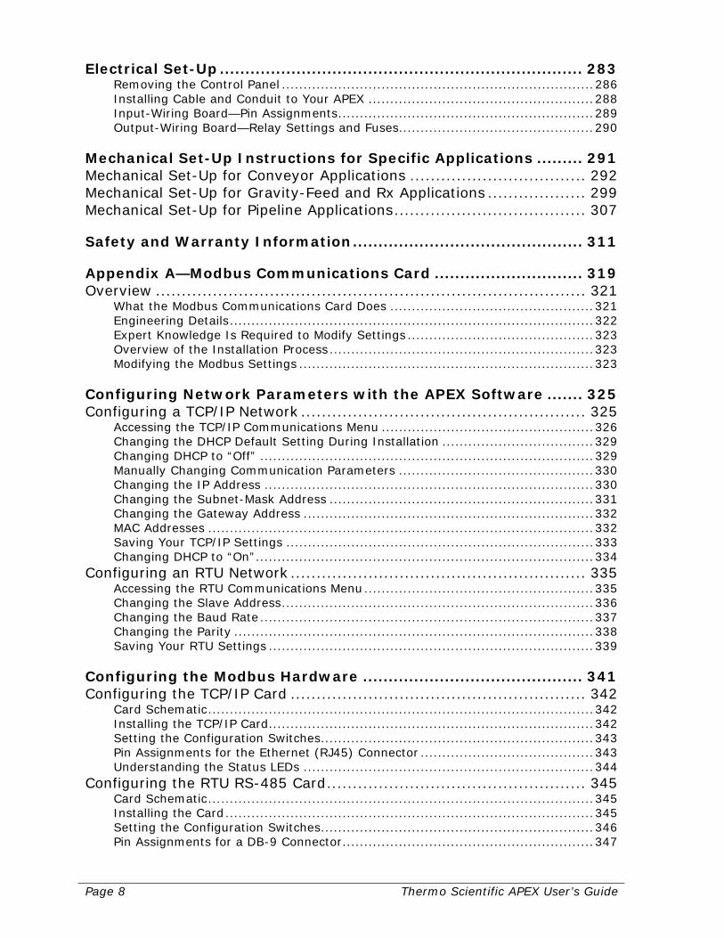
Electrical Set-Up ....................................................................... 283 Removing the Control Panel ........................................................................ 286 Installing Cable and Conduit to Your APEX .................................................... 288 Input-Wiring Board—Pin Assignments ........................................................... 289 Output-Wiring Board—Relay Settings and Fuses ............................................. 290
Mechanical Set-Up Instructions for Specific Applications ......... 291 Mechanical Set-Up for Conveyor Applications .................................. 292 Mechanical Set-Up for Gravity-Feed and Rx Applications ................... 299 Mechanical Set-Up for Pipeline Applications ..................................... 307 Safety and Warranty Information ............................................. 311 Appendix A—Modbus Communications Card ............................. 319 Overview ................................................................................... 321
What the Modbus Communications Card Does ............................................... 321 Engineering Details .................................................................................... 322 Expert Knowledge Is Required to Modify Settings ........................................... 323 Overview of the Installation Process ............................................................. 323 Modifying the Modbus Settings .................................................................... 323
Configuring Network Parameters with the APEX Software ....... 325 Configuring a TCP/IP Network ....................................................... 325
Accessing the TCP/IP Communications Menu ................................................. 326 Changing the DHCP Default Setting During Installation ................................... 329 Changing DHCP to “Off” ............................................................................. 329 Manually Changing Communication Parameters ............................................. 330 Changing the IP Address ............................................................................ 330 Changing the Subnet-Mask Address ............................................................. 331 Changing the Gateway Address ................................................................... 332 MAC Addresses ......................................................................................... 332 Saving Your TCP/IP Settings ....................................................................... 333 Changing DHCP to “On” .............................................................................. 334
Configuring an RTU Network ......................................................... 335 Accessing the RTU Communications Menu ..................................................... 335 Changing the Slave Address ........................................................................ 336 Changing the Baud Rate ............................................................................. 337 Changing the Parity ................................................................................... 338 Saving Your RTU Settings ........................................................................... 339
Configuring the Modbus Hardware ........................................... 341 Configuring the TCP/IP Card ......................................................... 342
Card Schematic ......................................................................................... 342 Installing the TCP/IP Card ........................................................................... 342 Setting the Configuration Switches ............................................................... 343 Pin Assignments for the Ethernet (RJ45) Connector ........................................ 343 Understanding the Status LEDs ................................................................... 344
Configuring the RTU RS-485 Card .................................................. 345 Card Schematic ......................................................................................... 345 Installing the Card ..................................................................................... 345 Setting the Configuration Switches ............................................................... 346 Pin Assignments for a DB-9 Connector .......................................................... 347
Thermo Scientific APEX User’s Guide Page 9
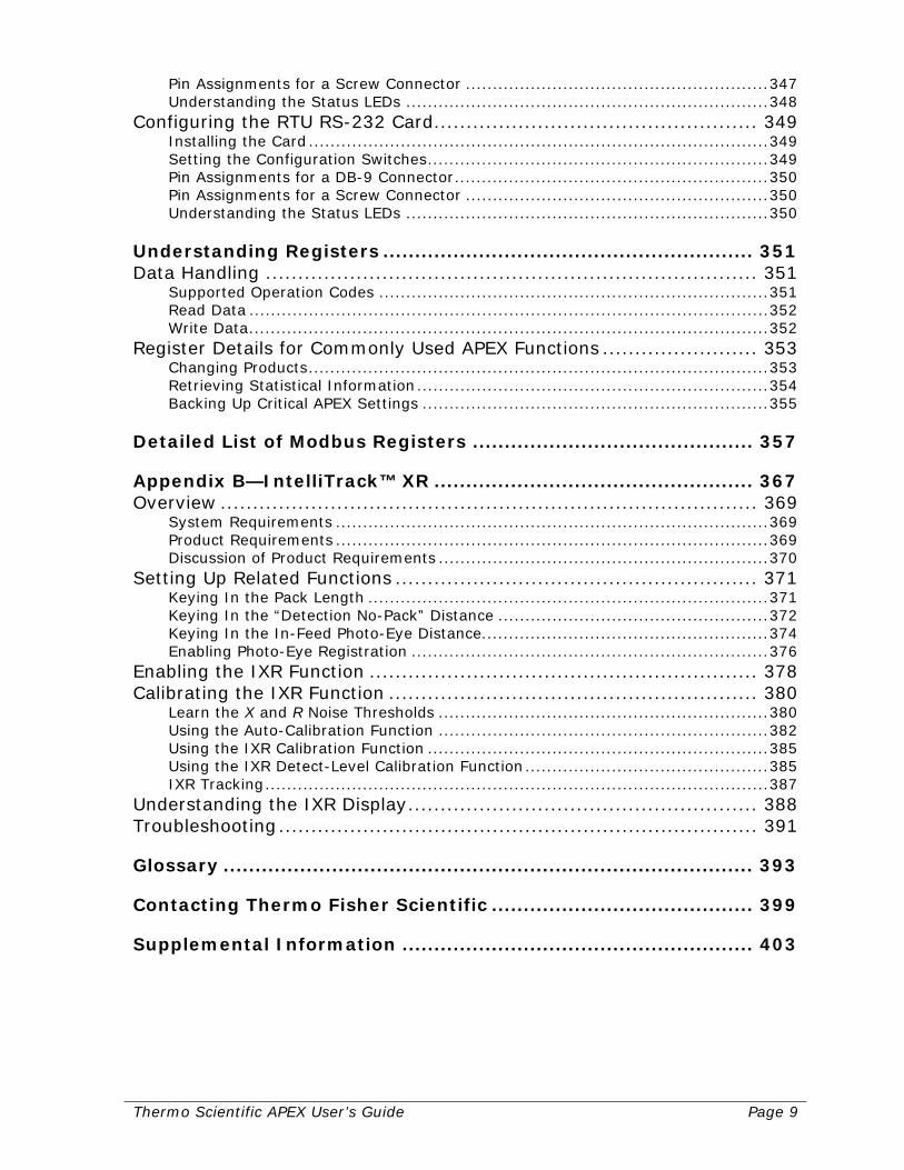
Pin Assignments for a Screw Connector ........................................................ 347 Understanding the Status LEDs ................................................................... 348
Configuring the RTU RS-232 Card .................................................. 349 Installing the Card ..................................................................................... 349 Setting the Configuration Switches ............................................................... 349 Pin Assignments for a DB-9 Connector .......................................................... 350 Pin Assignments for a Screw Connector ........................................................ 350 Understanding the Status LEDs ................................................................... 350
Understanding Registers .......................................................... 351 Data Handling ............................................................................ 351
Supported Operation Codes ........................................................................ 351 Read Data ................................................................................................ 352 Write Data ................................................................................................ 352
Register Details for Commonly Used APEX Functions ........................ 353 Changing Products ..................................................................................... 353 Retrieving Statistical Information ................................................................. 354 Backing Up Critical APEX Settings ................................................................ 355
Detailed List of Modbus Registers ............................................ 357 Appendix B—IntelliTrack™ XR .................................................. 367 Overview ................................................................................... 369
System Requirements ................................................................................ 369 Product Requirements ................................................................................ 369 Discussion of Product Requirements ............................................................. 370
Setting Up Related Functions ........................................................ 371 Keying In the Pack Length .......................................................................... 371 Keying In the “Detection No-Pack” Distance .................................................. 372 Keying In the In-Feed Photo-Eye Distance ..................................................... 374 Enabling Photo-Eye Registration .................................................................. 376
Enabling the IXR Function ............................................................ 378 Calibrating the IXR Function ......................................................... 380
Learn the X and R Noise Thresholds ............................................................. 380 Using the Auto-Calibration Function ............................................................. 382 Using the IXR Calibration Function ............................................................... 385 Using the IXR Detect-Level Calibration Function ............................................. 385 IXR Tracking ............................................................................................. 387
Understanding the IXR Display ...................................................... 388 Troubleshooting .......................................................................... 391 Glossary ................................................................................... 393 Contacting Thermo Fisher Scientific ......................................... 399 Supplemental Information ....................................................... 403

Page 10 Thermo Scientific APEX User’s Guide

Thermo Scientific APEX User’s Guide Page 11
Getting Started Congratulations on the purchase of your new Thermo Scientific APEX metal detector! The first thing to do is unpack your detector and complete the electrical installation and application-specific mechanical set-up. For instructions on how to do this, go to page 283. Now that your APEX™ detector is properly installed, you are ready—and, we hope, eager—to learn how to use it. Here, in outline, is what you will learn in this section.
Setting Global and Application-Specific Parameters Once the detector is installed and ready to check your products for the presence of metallic contaminants, you will use the detector’s control panel to set up various global and application-specific parameters. In this manual, the term “product” refers to anything you are testing for the presence of metallic contaminants. Whenever you encounter a technical term you do not understand in this manual, please go to the Glossary on page 393 for a brief explanation. Global parameters are ones that you pretty much “set and forget,” because they define how you want the detector’s display screen to appear, what language and units (feet or meters) you prefer to use, and so on. In other words, global parameters are ones that you will not change very often. In contrast, application-specific parameters are ones you use to get your particular type of application (conveyor, gravity-feed, pipeline, or pharmaceutical) set up and running properly. Application-specific parameters sometimes need to be fine tuned to optimize the detector’s performance for your particular operating environment.
Setting Product Parameters You use the detector’s control panel to set up various product parameters. The most critical product parameters you need to set are the following.
• Values for the X and R Noise Thresholds The X and R thresholds are background noise thresholds that are learned by the detector with no product present. In conveyor applications, the thresholds are learned with the conveyor running, but with no product present on the conveyor or in the search head. Similarly, in gravity-feed, pipeline, and pharmaceutical applications, the thresholds are learned with no product present in the duct, pipe or chute. When the X and R noise thresholds are exceeded, they indicate the presence of product—as shown by the activation of the green product-LED on the detector’s control panel.
• The Detect-Level Value Any signal from the detector’s search head that exceeds the detect level, will be tagged as a contaminant. As a general rule, the detect level should exceed the level of the background noise by a factor of 2–3 times.
Page 12 Thermo Scientific APEX User’s Guide
Managing Product-Rejection Parameters Once the detector is up and running and detecting metal contaminants, the next task is to set up the all-important product-rejection parameters, which fine tune the accept-or-reject process for your products. Which parameters you use, however, depend on the type of application (conveyor, gravity-feed, pipeline, or pharmaceutical) you are using.
• Conveyor Applications In this application, a conveyor belt is used to pass the product through the detector’s search head.
• Gravity-Feed (also known as “Drop-Through”) Applications The search head surrounds a vertical duct where the product drops through the duct under the influence of gravity. The detector’s search head is installed around the outside of the duct.
• Pipeline Applications The detector’s search head is installed surrounding a pipe, where product is flowing under pressure.
• Pharmaceutical Applications The search head surrounds a chute where the product drops through the chute under the influence of gravity. The detector’s search head is installed around the outside of the chute.
Choosing Your Application Type Clearly, the product parameters and product-rejection parameters used by the APEX vary depending on the type of application you are using. As a result, you should now go to the specific section in this manual that explains the detailed set-up procedures for your particular type of application. Find the relevant section as follows.
• Conveyor applications—Go to the page that follows this one (page 13).
• Gravity-feed applications—Go to page 63.
• Pipeline applications—Go to page 79.
• Pharmaceutical (Rx) applications—Go to page 95.
Thermo Scientific APEX User’s Guide Page 13
Setting Up Conveyor Applications The purpose of this section is to present you with a brief tutorial, allowing you to get your conveyor application up and running as quickly as possible. Here is an outline of what you will be learning. If you are already familiar with some of the information covered, you can always skip ahead to the next section. Understanding Your Detector In this section you will learn how to…
• Use the detector’s display panel. • Navigate the detector’s menus and sub-menus. • Set up global parameters for the detector.
Setting Up the Conveyor and Photo Eye In this section you will learn how to…
• Set up the conveyor parameters. • Set up the photo-eye parameters.
Setting Product Parameters In this section you will learn how to…
• Key in pack length. • Key in no-pack distance. • Key in pack gap.
Setting Product-Reject Parameters In this section you will learn how to…
• Key in the distance to the product reject device. • Key in the signal duration for the product reject device.
Calibrating Your Detector In this section you will learn how to…
• Establish a noise threshold with no product present in the search head. • Calibrate the speed filter using a ferrous (or other) test stick. • Establish basic product parameters (detect level and phase-angle). • Have the detector do an AuditCheck learn, if applicable.
Understanding Technical Terms If you encounter a technical term you do not understand in these sections, please refer to the Glossary on page 393. For example, the word “product” means anything the detector is testing for the presence of metal contaminants, and is a word you will encounter often in this manual. Let’s get started!
Page 14 Thermo Scientific APEX User’s Guide
Understanding Your Detector This section helps you understand the detector’s control panel and Main Menu, and explains how to set up three global (“set it and forget it”) parameters—language, help text, and units of measure.
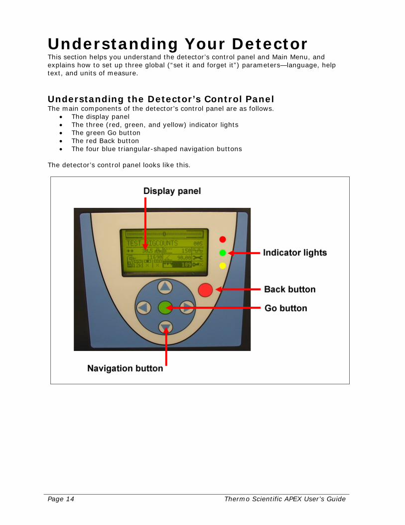
Understanding the Detector’s Control Panel The main components of the detector’s control panel are as follows.
• The display panel • The three (red, green, and yellow) indicator lights • The green Go button • The red Back button • The four blue triangular-shaped navigation buttons
The detector’s control panel looks like this.
Thermo Scientific APEX User’s Guide Page 15
The Display Panel The display panel allows you to access all the detector’s functions. The Indicator Lights These give you a quick overview of how the detector is functioning.
• Red—Flashing once indicates an excess product effect; steady indicates a fault. • Green—Indicates a product is present in the detector’s search head. • Yellow—Indicates a contaminant has been detected in the product.
The Navigation Buttons These allow you to navigate around the detector’s menus and sub-menus. When you press a navigation button, the display highlights an adjacent function (using a black background). You access the highlighted function by pressing the Go button. In addition, the four navigation buttons are used increase or decrease numbers and select characters and settings in various menus and input screens. The Go Button Press the Go button to select or start one of the detector’s functions. The Back Button Press the Back button to stop one of the detector’s functions or to return to the previous menu screen. Pressing the Back button repeatedly will always take you back to the detector’s Main Menu.
Using the Detector’s Buttons The detector’s buttons—unlike those on a cell phone, for example—are not activated by direct mechanical force. Instead, a sensor below the image of the button on the control panel detects the movement of your finger to and away from the button’s location. As a result, the best way to activate the button is to lightly tap the button and—the key point here—immediately move your finger away from the button. For most people, this to-and-away motion is not intuitive but, with a little practice, you will find this is the best way to activate the detector’s buttons.
Page 16 Thermo Scientific APEX User’s Guide
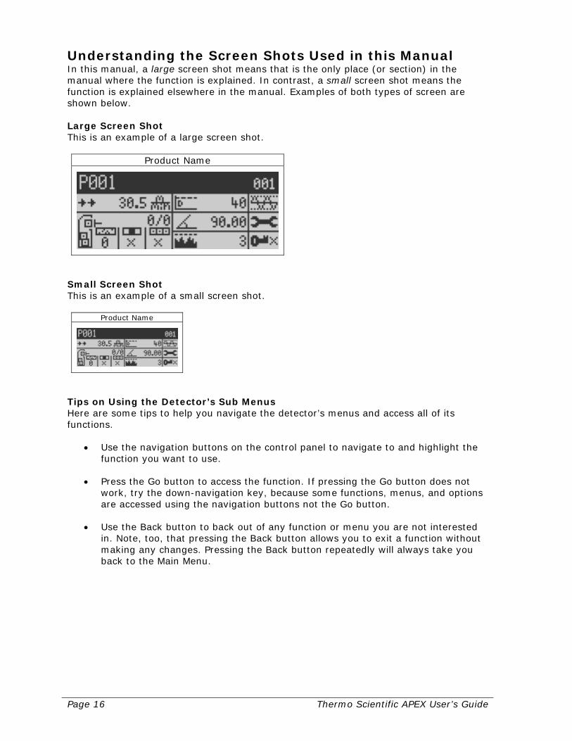
Understanding the Screen Shots Used in this Manual In this manual, a large screen shot means that is the only place (or section) in the manual where the function is explained. In contrast, a small screen shot means the function is explained elsewhere in the manual. Examples of both types of screen are shown below. Large Screen Shot This is an example of a large screen shot.
Product Name
Small Screen Shot This is an example of a small screen shot.
Product Name
Tips on Using the Detector’s Sub Menus Here are some tips to help you navigate the detector’s menus and access all of its functions.
• Use the navigation buttons on the control panel to navigate to and highlight the function you want to use.
• Press the Go button to access the function. If pressing the Go button does not work, try the down-navigation key, because some functions, menus, and options are accessed using the navigation buttons not the Go button.
• Use the Back button to back out of any function or menu you are not interested in. Note, too, that pressing the Back button allows you to exit a function without making any changes. Pressing the Back button repeatedly will always take you back to the Main Menu.

Thermo Scientific APEX User’s Guide Page 17
How to Use the Parameter Input Screens Parameter input screens are used to set (or verify) a value for a particular function you are interested in. The right-hand number in all input screens is marked above and below with a small triangle—indicating that all the numbers in the screen can be changed using the navigation buttons.
Sample Input Screen
• Use the up-navigation button to increase the number marked by triangles. • Use the down-navigation button to decrease the number marked by triangles. • Use the left-navigation button to move to the number to the left. • Use the right-navigation button to move to the number to the right.
Understanding the Detector’s Main Menu In this section you are going to learn to navigate around some of the detector’s menus and input screens. More specifically, you are going to set up a number of global parameters for the detector. Global parameters are ones you set at the start of a project, because this type of parameter—once set—does not often need to be changed. You are going to do the following.
• Choose the language shown in the display panel. • Remove the bar-graph display (at the top of the Main Menu) and replace it with
the more informative Help Text display. • Set the appropriate units of measure (meters or feet), so the detector’s menus
display the units you prefer to work with.
Choosing a Language The default language for the display panel is English, but it can also display help text in the following nine languages.
• French • German • Italian • Spanish • Dutch • Chinese • Czech • Russian • Polish
If you want to use a language other than English, follow the instructions below. (continued…)

Page 18 Thermo Scientific APEX User’s Guide
1) Turn on the detector and the Main Menu screen appears.
2) Press the navigation buttons to select the system and tools menu, as shown below.
3) Press the Go button, and page 1 of the system and tools menu appears.
Notice the notation “1/5” in the screen above. This tells you that you are currently on page 1 in the system and tools menu, which is five pages long.
Thermo Scientific APEX User’s Guide Page 19
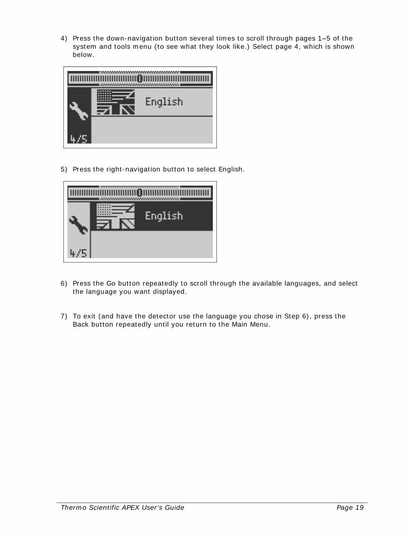
4) Press the down-navigation button several times to scroll through pages 1–5 of the system and tools menu (to see what they look like.) Select page 4, which is shown below.
5) Press the right-navigation button to select English.
6) Press the Go button repeatedly to scroll through the available languages, and select
the language you want displayed. 7) To exit (and have the detector use the language you chose in Step 6), press the
Back button repeatedly until you return to the Main Menu.
Page 20 Thermo Scientific APEX User’s Guide
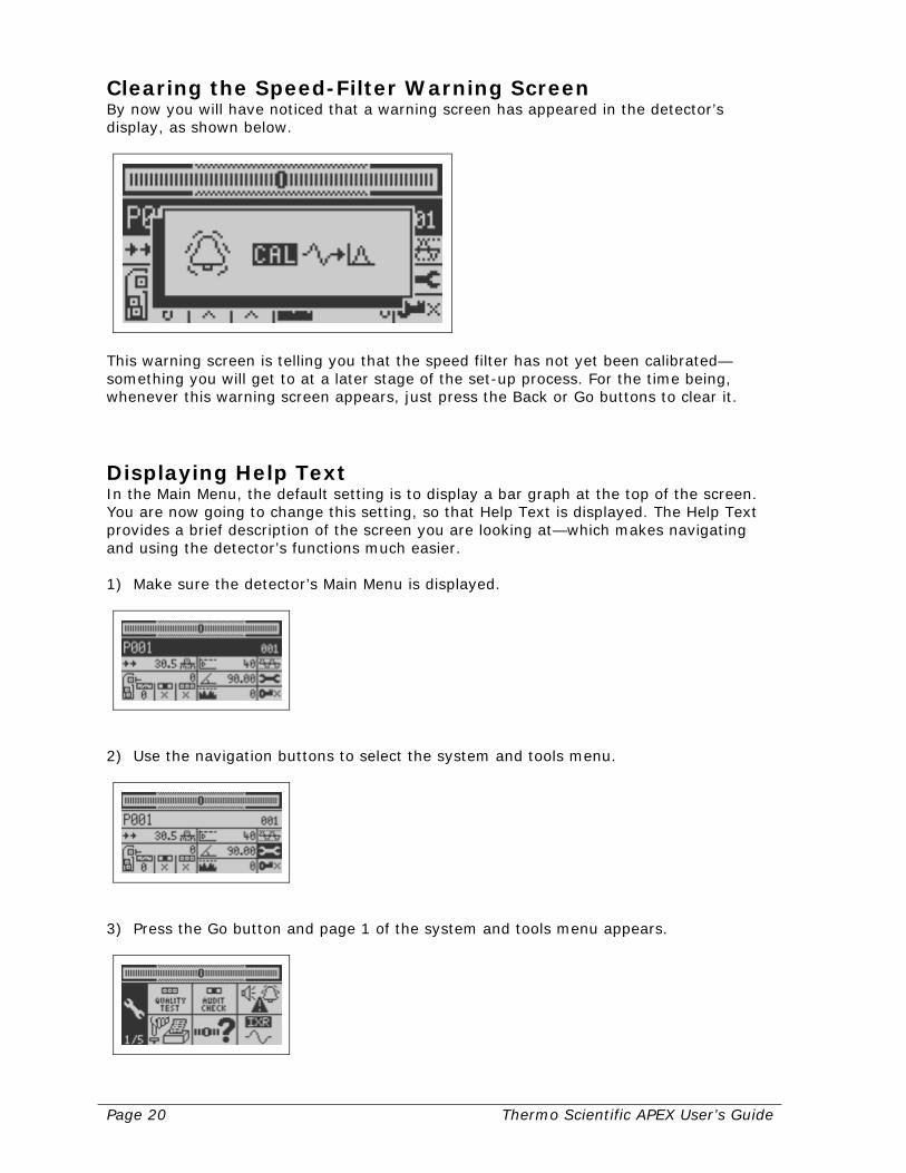
Clearing the Speed-Filter Warning Screen By now you will have noticed that a warning screen has appeared in the detector’s display, as shown below.
This warning screen is telling you that the speed filter has not yet been calibrated—something you will get to at a later stage of the set-up process. For the time being, whenever this warning screen appears, just press the Back or Go buttons to clear it.
Displaying Help Text In the Main Menu, the default setting is to display a bar graph at the top of the screen. You are now going to change this setting, so that Help Text is displayed. The Help Text provides a brief description of the screen you are looking at—which makes navigating and using the detector’s functions much easier. 1) Make sure the detector’s Main Menu is displayed.
2) Use the navigation buttons to select the system and tools menu.
3) Press the Go button and page 1 of the system and tools menu appears.

Thermo Scientific APEX User’s Guide Page 21
4) Use the navigation buttons to select the bar-graph/Help-Text menu.
5) Press the Go button, and the following screen appears.
6) Press the Go button once (to toggle the screen from the bar-graph setting to the
Help Text setting). Notice that descriptive Help Text is now displayed at the top of the screen (and will continue to be displayed until you change this setting).
Bargraph and Help Setup
7) Press the Back button repeatedly to return to the Main Menu.
Page 22 Thermo Scientific APEX User’s Guide
Choosing Your Preferred Units of Measure The display panel presents information—such as conveyor speed—in either metric (meters) or imperial units (feet and inches). Follow these instructions to the set units you prefer to use and have the detector display. 1) Make sure the detector’s Main Menu is displayed.
Product Name
2) Use the navigation buttons to select the system and tools menu.
System and Tools
3) Press the Go button and page 1 of the system and tools menu appears.
System and Tools Page 1
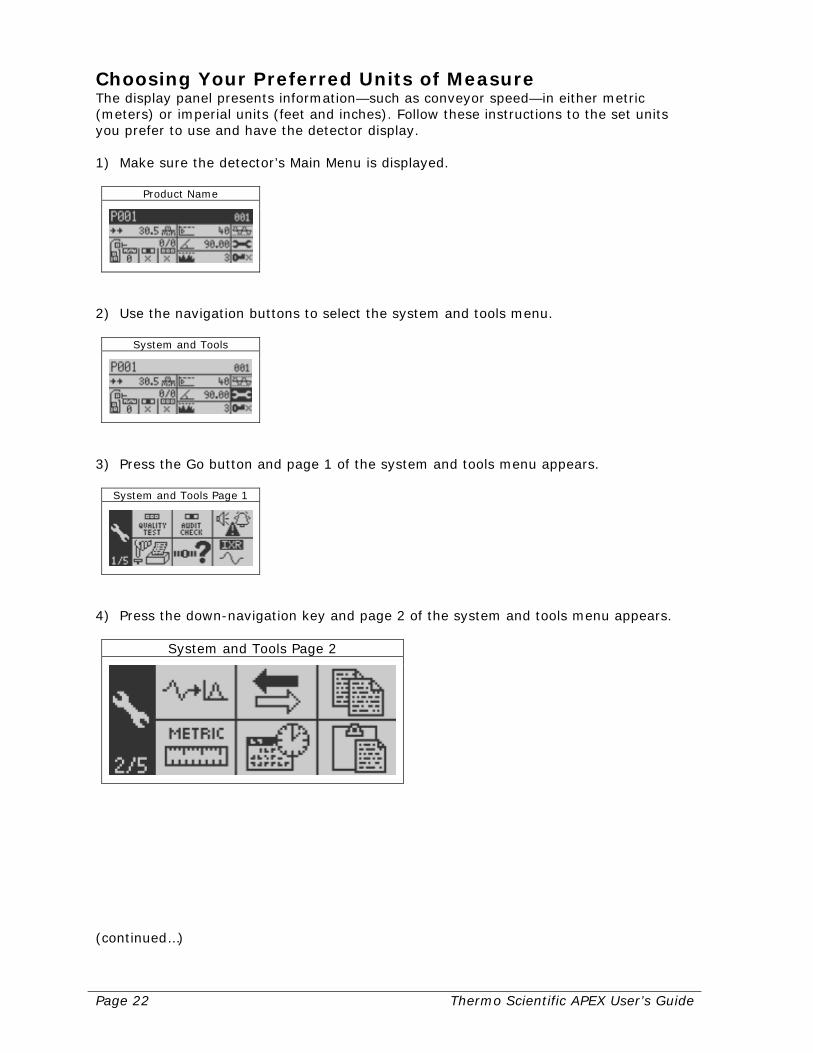
4) Press the down-navigation key and page 2 of the system and tools menu appears.
System and Tools Page 2
(continued…)

Thermo Scientific APEX User’s Guide Page 23
5) Use the navigation buttons to select the metric/imperial function.
Metric/Imperial Units
6) Press the Go button to toggle between imperial and metric units. Highlight the units
of measure (meters, or feet and inches) you prefer to use. 7) To exit (and select the units you chose in Step 6), press the Back button repeatedly
until you get back to the Main Menu.
Page 24 Thermo Scientific APEX User’s Guide
Naming the Product In the examples that follow, imagine you are a lead engineer in a dairy and are setting up the APEX detector to make sure no metallic contaminants have dropped into the dairy’s products during the manufacturing process. Your first assignment is to test packets of salted butter for the presence of metallic contaminants. The packets of salted butter are rectangular in shape and are placed at regular intervals (with a space between each packet) on a conveyor that takes them through the detector’s search-head for analysis. On the other side of the detector, contaminated packets are pushed off the conveyor into a rejects bin by a mechanical arm—your reject device. A photo-electric cell (“photo eye”) attached to the detector monitor the flow of packets on the conveyor. This is photo-eye number 1, which monitors the packets just before they enter the detector’s search head. (This is a fairly typical set-up for a conveyor application.) Follow the instructions below to give a name to the product (in our example, salted butter) that you are testing. 1) Make sure the detector’s Main Menu is displayed.
Product Name
2) Press the Go button and page 1 of the product menu appears.
Product Calibrate and Name
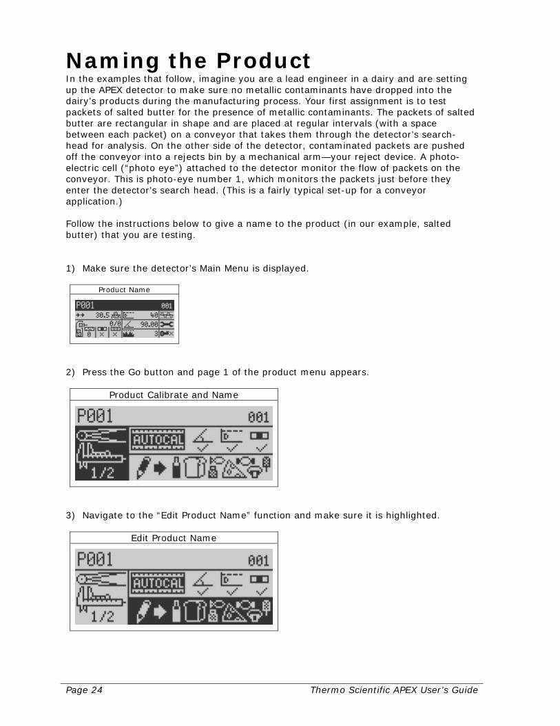
3) Navigate to the “Edit Product Name” function and make sure it is highlighted.
Edit Product Name
Thermo Scientific APEX User’s Guide Page 25
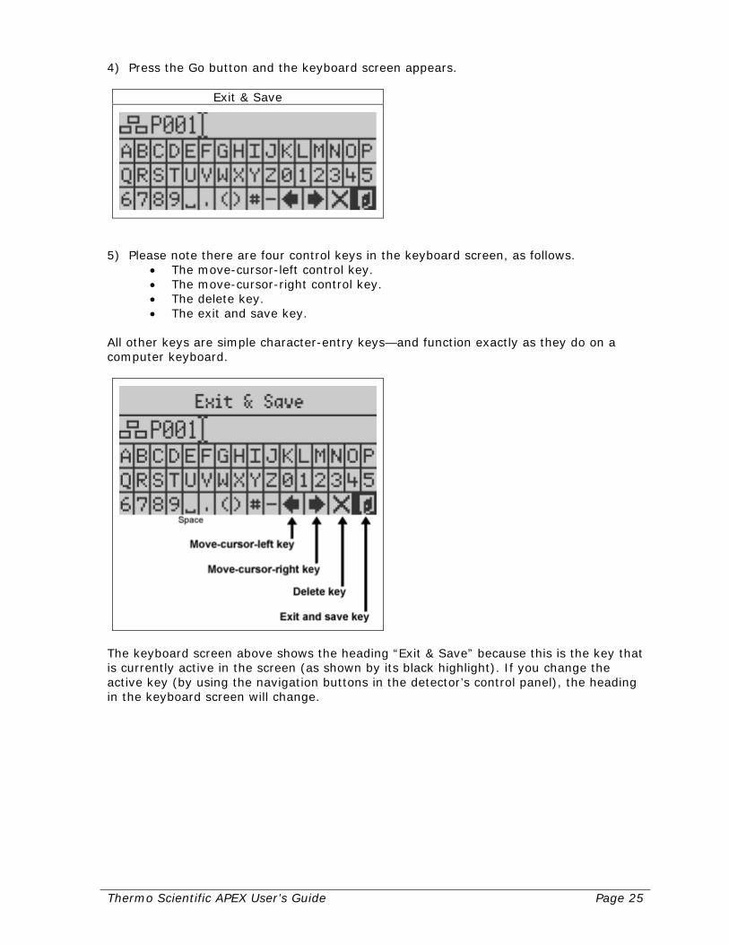
4) Press the Go button and the keyboard screen appears.
Exit & Save
5) Please note there are four control keys in the keyboard screen, as follows.
• The move-cursor-left control key. • The move-cursor-right control key. • The delete key. • The exit and save key.
All other keys are simple character-entry keys—and function exactly as they do on a computer keyboard.
The keyboard screen above shows the heading “Exit & Save” because this is the key that is currently active in the screen (as shown by its black highlight). If you change the active key (by using the navigation buttons in the detector’s control panel), the heading in the keyboard screen will change.
Page 26 Thermo Scientific APEX User’s Guide
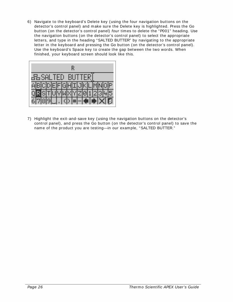
6) Navigate to the keyboard’s Delete key (using the four navigation buttons on the detector’s control panel) and make sure the Delete key is highlighted. Press the Go button (on the detector’s control panel) four times to delete the “P001” heading. Use the navigation buttons (on the detector’s control panel) to select the appropriate letters, and type in the heading “SALTED BUTTER” by navigating to the appropriate letter in the keyboard and pressing the Go button (on the detector’s control panel). Use the keyboard’s Space key to create the gap between the two words. When finished, your keyboard screen should look like this.
7) Highlight the exit-and-save key (using the navigation buttons on the detector’s
control panel), and press the Go button (on the detector’s control panel) to save the name of the product you are testing—in our example, “SALTED BUTTER.”
Thermo Scientific APEX User’s Guide Page 27
Setting Up the Conveyor and Photo-Eye This section assumes that the photo-eye is already connected to the detector (using Input 2 on the wiring board) and the conveyor is already running. (For more information about hard-wiring your detector, see page 289.) In addition, the example below assumes you are testing packets of salted butter, as described above in the “Naming the Product” section.
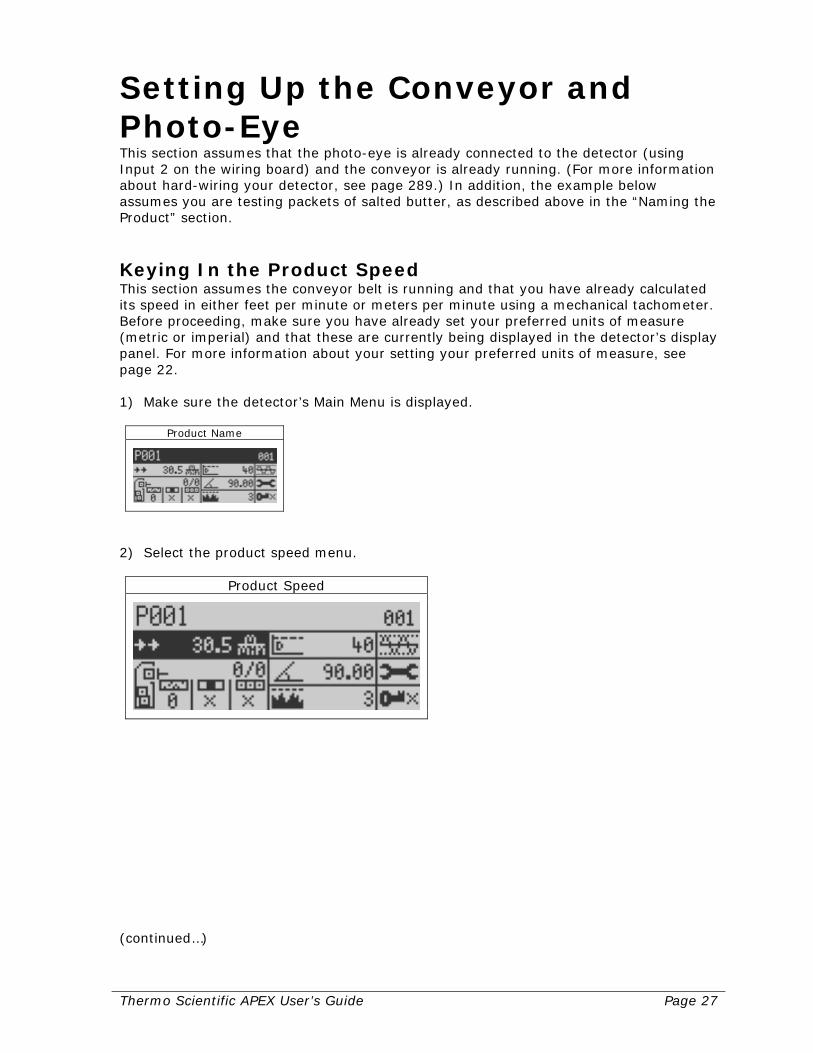
Keying In the Product Speed This section assumes the conveyor belt is running and that you have already calculated its speed in either feet per minute or meters per minute using a mechanical tachometer. Before proceeding, make sure you have already set your preferred units of measure (metric or imperial) and that these are currently being displayed in the detector’s display panel. For more information about your setting your preferred units of measure, see page 22. 1) Make sure the detector’s Main Menu is displayed.
Product Name
2) Select the product speed menu.
Product Speed
(continued…)
Page 28 Thermo Scientific APEX User’s Guide
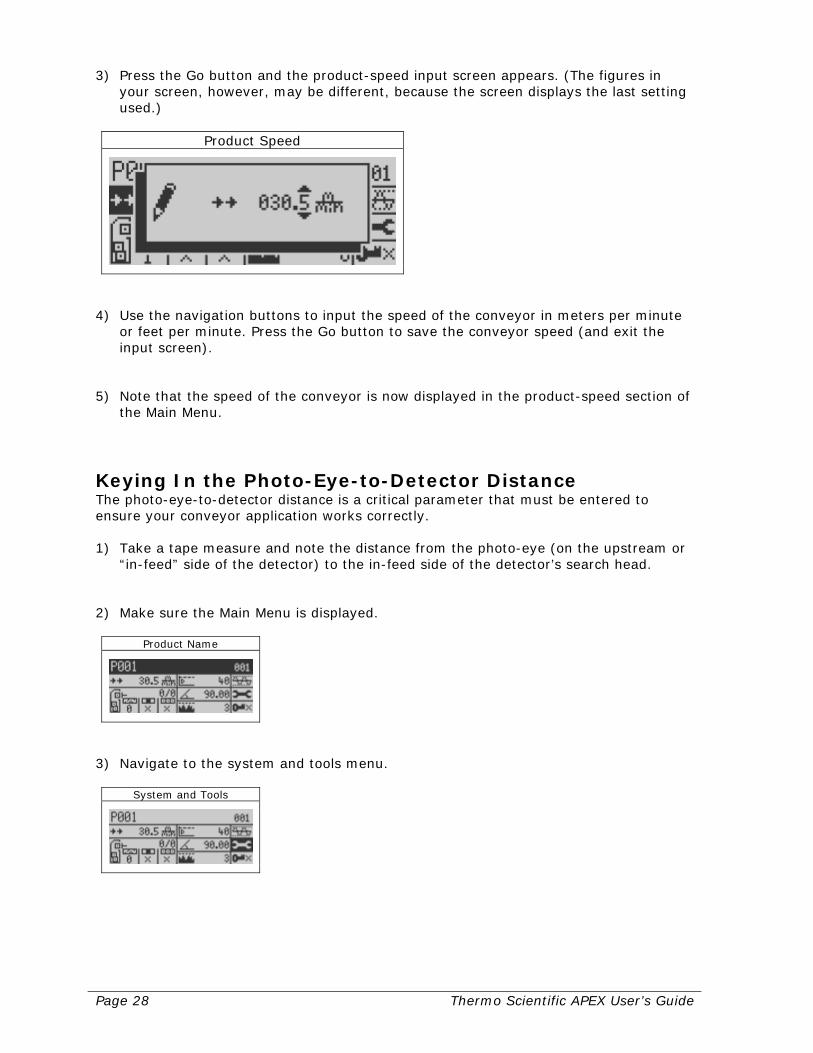
3) Press the Go button and the product-speed input screen appears. (The figures in your screen, however, may be different, because the screen displays the last setting used.)
Product Speed
4) Use the navigation buttons to input the speed of the conveyor in meters per minute
or feet per minute. Press the Go button to save the conveyor speed (and exit the input screen).
5) Note that the speed of the conveyor is now displayed in the product-speed section of
the Main Menu.
Keying In the Photo-Eye-to-Detector Distance The photo-eye-to-detector distance is a critical parameter that must be entered to ensure your conveyor application works correctly. 1) Take a tape measure and note the distance from the photo-eye (on the upstream or
“in-feed” side of the detector) to the in-feed side of the detector’s search head. 2) Make sure the Main Menu is displayed.
Product Name
3) Navigate to the system and tools menu.
System and Tools
Thermo Scientific APEX User’s Guide Page 29
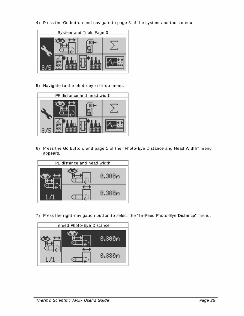
4) Press the Go button and navigate to page 3 of the system and tools menu.
System and Tools Page 3
5) Navigate to the photo-eye set-up menu.
PE distance and head width
6) Press the Go button, and page 1 of the “Photo-Eye Distance and Head Width” menu
appears.
PE distance and head width
7) Press the right-navigation button to select the “In-Feed Photo-Eye Distance” menu.
Infeed Photo-Eye Distance

Page 30 Thermo Scientific APEX User’s Guide
8) Press the Go button, and an input screen appears. (The figures in your screen, however, may be different, because the screen displays the last setting used.)
Infeed Photo-Eye Distance
9) Use the navigation buttons to input the distance from the photo-eye to the center of
the detector head. (In our example, we would enter a distance in centimeters and millimeters.) Press the Go button to save your setting and exit the input screen).
Checking the Polarity of the Photo-Eye Input This section assumes that your photo-eye is already connected to Input 2 on the detector’s wiring board. Photo-electric cells can send a signal to the detector, either when it detects light or when it detects dark. A light-activated photo-cell sends a signal when light is detected, and a dark-activated photo-cell sends a signal when dark is detected. You need to tell the detector which type of photo-cell you are using. If you do not know for sure, key in a positive polarity in the input menu screen (step 7 below) and, if that does not work, try a negative polarity. In addition, make sure the photo-eye is hard wired to Input 2 on the detector’s wiring board. (For more information about input wiring, see pages 222 and 289.) 1) Follow steps 1–4 in the “Choosing Your Preferred Units of Measure” section on
page 22 to get to the menu shown below—page 2 of the system and tools menu.
System and Tools Page 2
2) Navigate to the inputs and outputs menu.
Input and Outputs
Thermo Scientific APEX User’s Guide Page 31
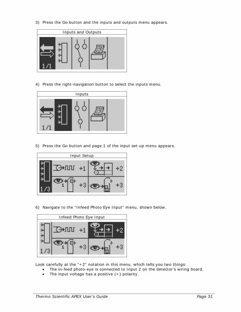
3) Press the Go button and the inputs and outputs menu appears.
Inputs and Outputs
4) Press the right-navigation button to select the inputs menu.
Inputs
5) Press the Go button and page 1 of the input set-up menu appears.
Input Setup
6) Navigate to the “Infeed Photo Eye Input” menu, shown below.
Infeed Photo Eye Input
Look carefully at the “+2” notation in this menu, which tells you two things:
• The in-feed photo-eye is connected to Input 2 on the detector’s wiring board. • The input voltage has a positive (+) polarity.

Page 32 Thermo Scientific APEX User’s Guide
7) If you need to change the polarity on Input 2 to a negative polarity, press the Go button, and the in-feed photo-eye input screen appears.
Infeed Photo Eye Input
8) Press the left-navigation button to underline the + sign. 9) Press the down-navigation button to change the polarity to minus (–), as shown
below.
Infeed Photo Eye Input
Note, if your photo eye were wired to Input 3 (or any other Input between 1 and 6), this menu would be used to make the change. For a positive polarity on Input 3, for example, you would enter “+3” in this input screen. 10) Press the Go button to save your setting and exit the input screen.
Selecting the Correct Photo Registration for Rejects If you are using a photo eye to control your reject device, this function allows you to do the following.
• Make accurate and consistent rejects using a variety of reject devices—such as drop-nose, retracting-belt, air-pusher, and air-reject systems.
• Make accurate and consistent rejects, even when the gaps between your individual units of product varies.
This function is particularly useful if you are inspecting packages that exceed six inches in length. (Here “length” means that, as the front end of the package enters the search head, the distance to its trailing edge is six inches or more.) When testing products longer than six inches, using a photo eye (and the appropriate parameters for the photo-registration function) allows you to accurately reject contaminated products—

Thermo Scientific APEX User’s Guide Page 33
regardless of where the contamination is located in the package (at the front, in the middle, or at the back). Matching Your Photo-Registration Parameters to Your Reject Device It is important to match your photo-registration parameters to the type of reject device you are using. Rejects can be triggered in three different ways, as follows.
• By the leading-edge of the product. • By the middle of the product. • By the entire length of the product.
Use the following information to select the best photo-registration setting for your particular application. Leading-Edge Rejects This setting is recommended for drop-nose and retracting-belt reject devices. Middle-of-the-Product Rejects This setting is recommended for air-pusher and air-jet reject devices. Entire-Length Rejects This setting is recommended for applications where the gaps between the units of product are variable. When gaps vary, the photo eye registers the reject using the leading edge of the product, but automatically extends the reject duration to compensate for the length of the product. Setting Photo-Registration Parameters 1) Make sure the detector’s Main Menu is displayed.
Product Name
2) Navigate to the reject-totals menu.
Reject Totals
(continued…)
Page 34 Thermo Scientific APEX User’s Guide
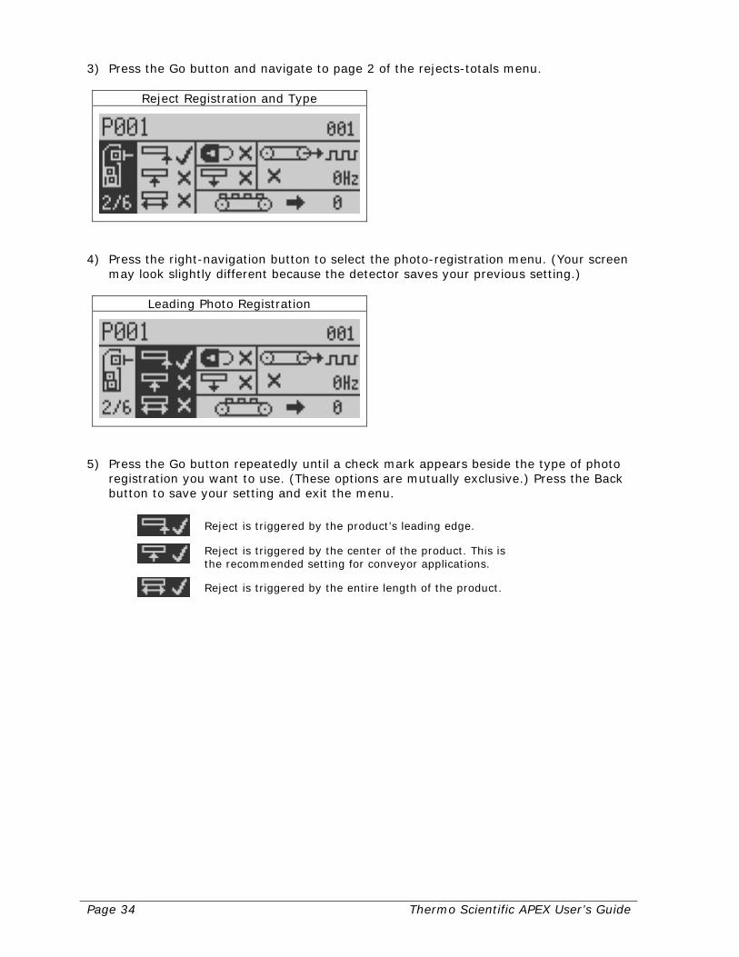
3) Press the Go button and navigate to page 2 of the rejects-totals menu.
Reject Registration and Type
4) Press the right-navigation button to select the photo-registration menu. (Your screen
may look slightly different because the detector saves your previous setting.)
Leading Photo Registration
5) Press the Go button repeatedly until a check mark appears beside the type of photo
registration you want to use. (These options are mutually exclusive.) Press the Back button to save your setting and exit the menu.
Reject is triggered by the product’s leading edge.
Reject is triggered by the center of the product. This is the recommended setting for conveyor applications.
Reject is triggered by the entire length of the product.
Thermo Scientific APEX User’s Guide Page 35
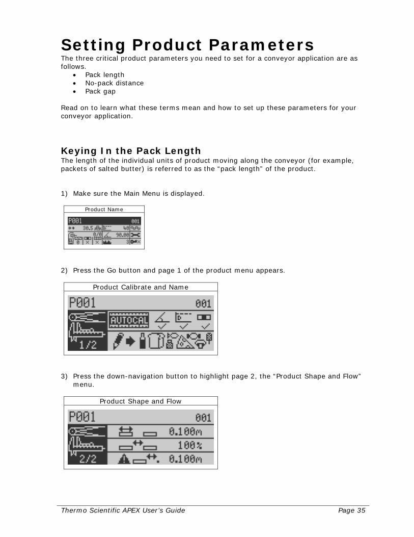
Setting Product Parameters The three critical product parameters you need to set for a conveyor application are as follows.
• Pack length • No-pack distance • Pack gap
Read on to learn what these terms mean and how to set up these parameters for your conveyor application.
Keying In the Pack Length The length of the individual units of product moving along the conveyor (for example, packets of salted butter) is referred to as the “pack length” of the product. 1) Make sure the Main Menu is displayed.
Product Name
2) Press the Go button and page 1 of the product menu appears.
Product Calibrate and Name
3) Press the down-navigation button to highlight page 2, the “Product Shape and Flow”
menu.
Product Shape and Flow
Page 36 Thermo Scientific APEX User’s Guide
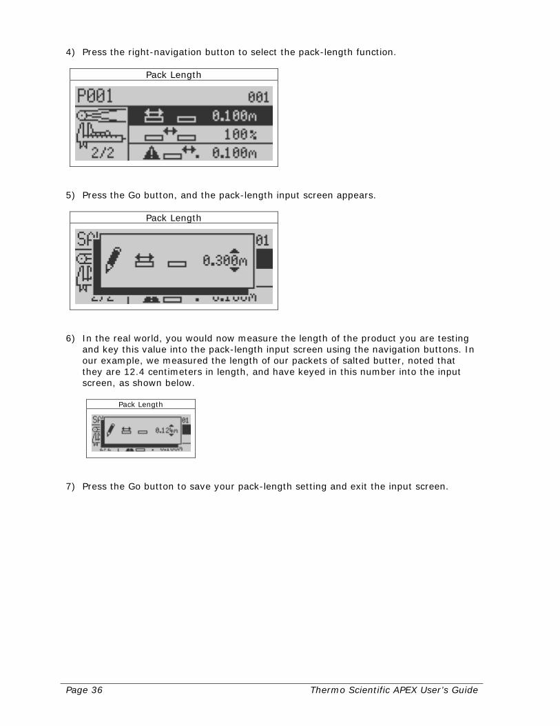
4) Press the right-navigation button to select the pack-length function.
Pack Length
5) Press the Go button, and the pack-length input screen appears.
Pack Length
6) In the real world, you would now measure the length of the product you are testing
and key this value into the pack-length input screen using the navigation buttons. In our example, we measured the length of our packets of salted butter, noted that they are 12.4 centimeters in length, and have keyed in this number into the input screen, as shown below.
Pack Length
7) Press the Go button to save your pack-length setting and exit the input screen.
Thermo Scientific APEX User’s Guide Page 37
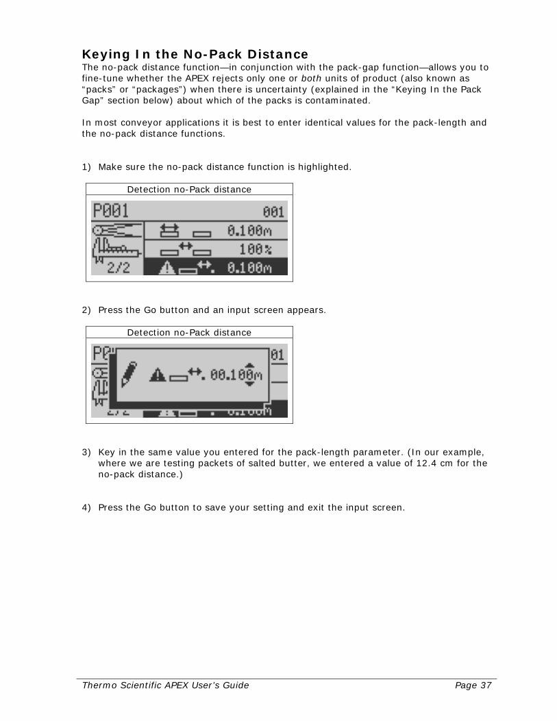
Keying In the No-Pack Distance The no-pack distance function—in conjunction with the pack-gap function—allows you to fine-tune whether the APEX rejects only one or both units of product (also known as “packs” or “packages”) when there is uncertainty (explained in the “Keying In the Pack Gap” section below) about which of the packs is contaminated. In most conveyor applications it is best to enter identical values for the pack-length and the no-pack distance functions. 1) Make sure the no-pack distance function is highlighted.
Detection no-Pack distance
2) Press the Go button and an input screen appears.
Detection no-Pack distance
3) Key in the same value you entered for the pack-length parameter. (In our example,
where we are testing packets of salted butter, we entered a value of 12.4 cm for the no-pack distance.)
4) Press the Go button to save your setting and exit the input screen.
Page 38 Thermo Scientific APEX User’s Guide
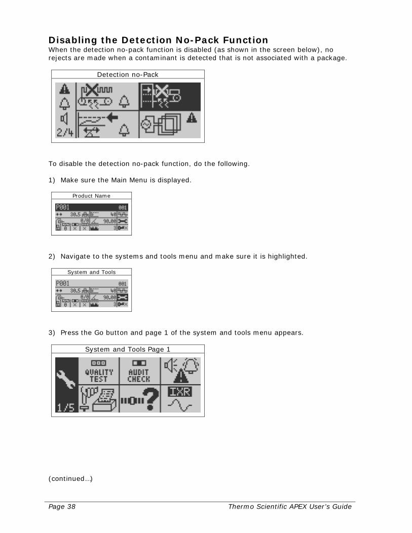
Disabling the Detection No-Pack Function When the detection no-pack function is disabled (as shown in the screen below), no rejects are made when a contaminant is detected that is not associated with a package.
Detection no-Pack
To disable the detection no-pack function, do the following. 1) Make sure the Main Menu is displayed.
Product Name
2) Navigate to the systems and tools menu and make sure it is highlighted.
System and Tools
3) Press the Go button and page 1 of the system and tools menu appears.
System and Tools Page 1
(continued…)

Thermo Scientific APEX User’s Guide Page 39
4) Navigate to the “Warnings, Alarms, and Faults” (WAFs) menu.
Warnings, Alarms & Faults
5) Press the Go button and page 1 of the WAFs menu appears.
Warnings, Alarms & Faults
6) Press the down-navigation button and page 2 of the menu appears.
Warnings, Alarms & Faults
7) Navigate to the “detection no-pack” function and make sure it is highlighted.
Detection, no-Pack
Note that, currently, when the APEX detects a contaminant that is not associated with a package, a fault results—as shown by the presence of the fault symbol in the menu.
Page 40 Thermo Scientific APEX User’s Guide
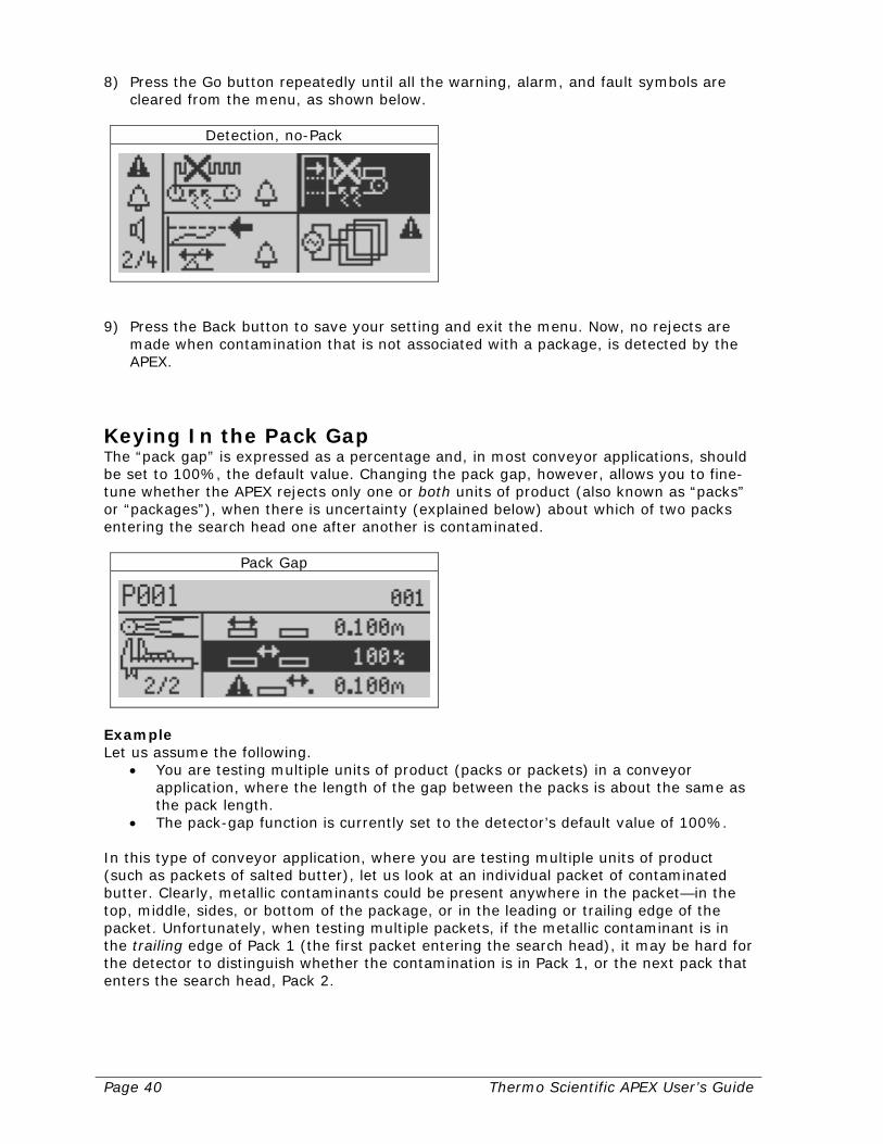
8) Press the Go button repeatedly until all the warning, alarm, and fault symbols are cleared from the menu, as shown below.
Detection, no-Pack
9) Press the Back button to save your setting and exit the menu. Now, no rejects are
made when contamination that is not associated with a package, is detected by the APEX.
Keying In the Pack Gap The “pack gap” is expressed as a percentage and, in most conveyor applications, should be set to 100%, the default value. Changing the pack gap, however, allows you to fine-tune whether the APEX rejects only one or both units of product (also known as “packs” or “packages”), when there is uncertainty (explained below) about which of two packs entering the search head one after another is contaminated.
Pack Gap
Example Let us assume the following.
• You are testing multiple units of product (packs or packets) in a conveyor application, where the length of the gap between the packs is about the same as the pack length.
• The pack-gap function is currently set to the detector’s default value of 100%. In this type of conveyor application, where you are testing multiple units of product (such as packets of salted butter), let us look at an individual packet of contaminated butter. Clearly, metallic contaminants could be present anywhere in the packet—in the top, middle, sides, or bottom of the package, or in the leading or trailing edge of the packet. Unfortunately, when testing multiple packets, if the metallic contaminant is in the trailing edge of Pack 1 (the first packet entering the search head), it may be hard for the detector to distinguish whether the contamination is in Pack 1, or the next pack that enters the search head, Pack 2.

Thermo Scientific APEX User’s Guide Page 41
Explanation of the Theory Underlying the Pack-Gap Function In the above example, if you enter a value of 100% for the pack-gap function, both packs are rejected, because—as shown in the diagram below—the overlap distance of the two packs falls within the 100% zone of the pack-gap function—which, in turn, falls within the no-pack distances for Pack 1 and Pack 2. No-pack distances are calculated by the detector, using input from the photo eye on the conveyor; or, they can be set by you, the user—as described above.
Thus, by setting appropriate values for the pack-gap function, the detector will take one of the following actions.
• Reject Pack 1 only • Reject both packs • Reject Pack 2 only
The following table illustrates what action the APEX will take, when a contaminant is detected in one of the positions A–F in the diagram above and the pack-gap function is set to 100%, 50%, or 25%. Pack gap Pack rejected when contaminant in the following position (A–F)
A B C D E F 100% 1 1 1 and 2 1 and 2 1 and 2 2 50% 1 1 1 and 2 1 and 2 1 and 2 2 25% 1 1 1 1 and 2 2 2
Page 42 Thermo Scientific APEX User’s Guide
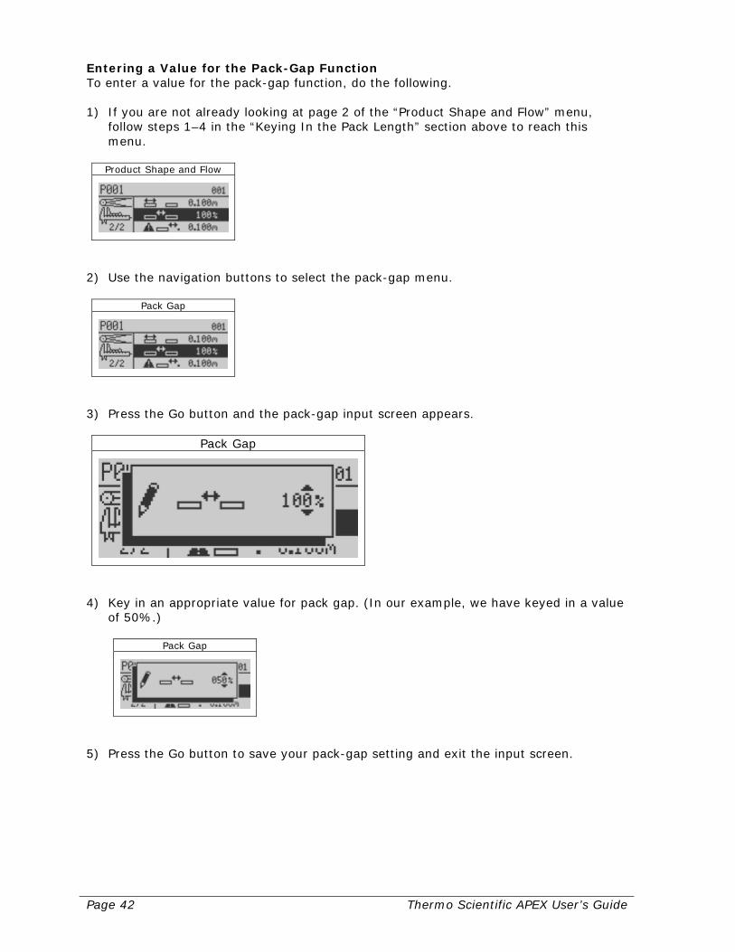
Entering a Value for the Pack-Gap Function To enter a value for the pack-gap function, do the following. 1) If you are not already looking at page 2 of the “Product Shape and Flow” menu,
follow steps 1–4 in the “Keying In the Pack Length” section above to reach this menu.
Product Shape and Flow
2) Use the navigation buttons to select the pack-gap menu.
Pack Gap
3) Press the Go button and the pack-gap input screen appears.
Pack Gap
4) Key in an appropriate value for pack gap. (In our example, we have keyed in a value
of 50%.)
Pack Gap
5) Press the Go button to save your pack-gap setting and exit the input screen.

Thermo Scientific APEX User’s Guide Page 43
Setting Reject Parameters This section assumes that the reject device you are using to remove contaminated products from the conveyor is already connected to the detector’s wiring board and ready to go to work. If a reject device is not already connected to your detector, see the “Mechanical Set-Up for Conveyor Applications” section on page 292. In this manual—and in the detector’s menus—the main reject device is referred to as the “Reject 1” device. Any secondary reject device is called the “Reject 2” device. The following sections are written on the assumption that you currently have only one reject device attached to your detector, a Reject-1 device. (For information about keying in parameters for a Reject-2 device, see page 141.)
Reject Totals
Measurements You Will Need Before Starting Imagine our packets of salted butter moving along the conveyor and the search head suddenly detects a packet containing a metallic contaminant. For now, the contaminated packet continues its journey out of the search head and along the conveyor. Around one meter from the detector, however, the packet passes the main reject device and is suddenly ejected from the conveyor into the reject bin. (One down, more to go!) However, before you can begin keying in parameters to control your reject device, you must have the following information ready.
• The distance from the downstream edge of the search head to the center of your
reject device. • The duration of the signal needed (expressed in seconds and hundredths of a
second) to activate your reject device. With this information in hand, you are now ready to key in the needed values. In our salted butter example, we are going to use the following values.
• Reject distance = 1.17 meters
• Reject-signal duration = 2.02 seconds
Page 44 Thermo Scientific APEX User’s Guide
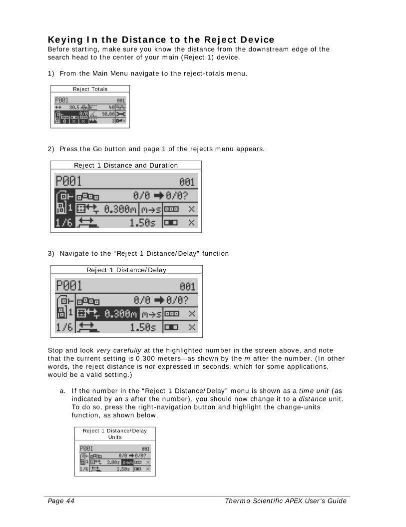
Keying In the Distance to the Reject Device Before starting, make sure you know the distance from the downstream edge of the search head to the center of your main (Reject 1) device. 1) From the Main Menu navigate to the reject-totals menu.
Reject Totals
2) Press the Go button and page 1 of the rejects menu appears.
Reject 1 Distance and Duration
3) Navigate to the “Reject 1 Distance/Delay” function
Reject 1 Distance/Delay
Stop and look very carefully at the highlighted number in the screen above, and note that the current setting is 0.300 meters—as shown by the m after the number. (In other words, the reject distance is not expressed in seconds, which for some applications, would be a valid setting.)
a. If the number in the “Reject 1 Distance/Delay” menu is shown as a time unit (as indicated by an s after the number), you should now change it to a distance unit. To do so, press the right-navigation button and highlight the change-units function, as shown below.
Reject 1 Distance/Delay Units
Thermo Scientific APEX User’s Guide Page 45
b. Press the Go button and the original units are changed from seconds to meters (or feet, if you have set these as your preferred distance unit). Notice that the numbers in the adjacent menu have now changed.
Reject 1 Distance/Delay
c. Make sure the screen shown in step 3 is displayed (the one where the reject
distance is expressed in meters). You are now ready to key in your reject distance in meters (or feet and inches, if these are your preferred units).
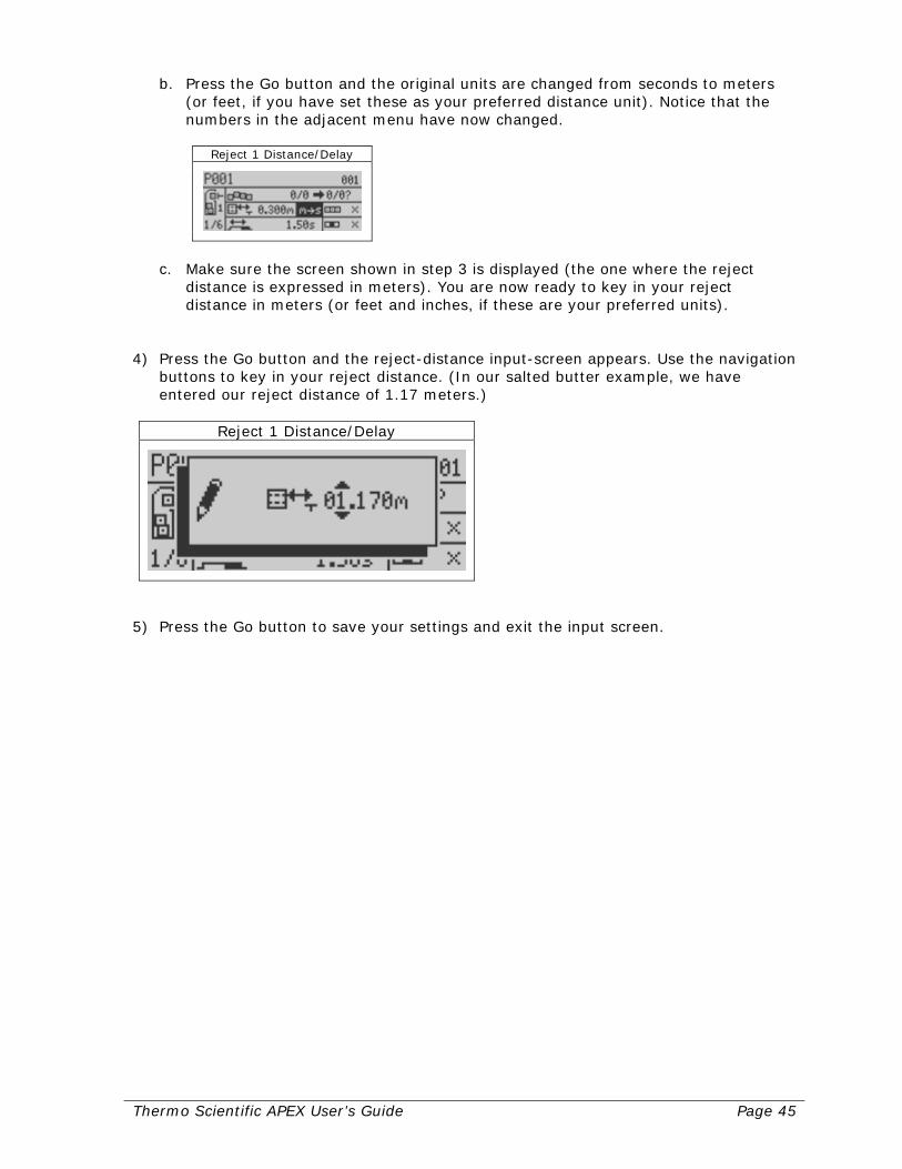
4) Press the Go button and the reject-distance input-screen appears. Use the navigation
buttons to key in your reject distance. (In our salted butter example, we have entered our reject distance of 1.17 meters.)
Reject 1 Distance/Delay
5) Press the Go button to save your settings and exit the input screen.
Page 46 Thermo Scientific APEX User’s Guide
Keying In the Signal Duration for the Reject Device Before starting, make sure you know the signal-duration time (expressed in seconds and hundredths of a second) needed to activate your main (Reject 1) device. 1) If you are not already on page 1 of the rejects menu, follow steps 1–2 in the “Keying
In Distance to the Reject Device” section to get there. 2) Navigate to the reject-device signal-duration function.
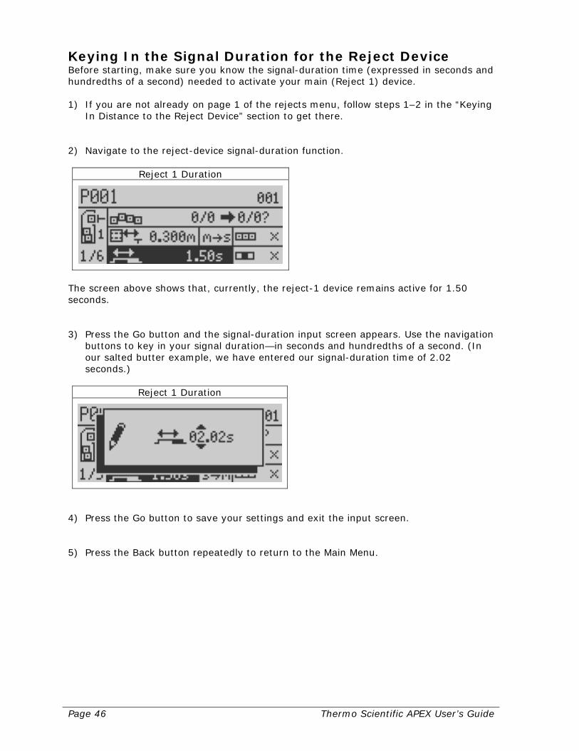
Reject 1 Duration
The screen above shows that, currently, the reject-1 device remains active for 1.50 seconds. 3) Press the Go button and the signal-duration input screen appears. Use the navigation
buttons to key in your signal duration—in seconds and hundredths of a second. (In our salted butter example, we have entered our signal-duration time of 2.02 seconds.)
Reject 1 Duration
4) Press the Go button to save your settings and exit the input screen. 5) Press the Back button repeatedly to return to the Main Menu.

Thermo Scientific APEX User’s Guide Page 47
Setting Contaminant-Detection Parameters This section assumes you have followed all the instructions from the start of the “Setting Up Conveyor Applications” to this point. The reason for this is that, before you can calibrate your detector, the parameters described above must already have been set. This section tells you how to do the following.
• Set up a monitoring baseline for the detector by calibrating the X and R noise thresholds, which must be done when no product is present in the search head.
• Calibrate the speed filter using a ferrous test stick (for most applications, use the 2.0 to 4.0 millimeter test stick). If the red indicator light on the control panel lights when you pass the 4.0 millimeter test stick, use a smaller size.
• Have the detector learn the appropriate detect level, phase angle, and peak signal settings by passing uncontaminated product through the search head.
• Have the detector do a Quality Test learn, if applicable.
• Have the detector do an AuditCheck learn, if applicable. Once you have finished this section, your detector will be set up and ready to go to work monitoring your product for the presence of metallic contaminants.
Establishing Noise Thresholds with No Product Present Before you can establish noise thresholds for the X and R signals, you must do the following.
• Turn on the conveyor. • Remove all product from the conveyor.
Now that the conveyor is running and no product is present in the search head, follow the instructions below to calibrate the detector’s settings for the X and R noise thresholds. 1) Make sure the Main Menu is displayed.
Product Name
(continued…)

Page 48 Thermo Scientific APEX User’s Guide
2) Navigate to the frequency and gain menu.
Frequency and Gain
3) Press the Go button and page 1 of the “Frequency, Gain & Inhibit” menu appears.
Frequency, Gain & Inhibit
4) Press the down-navigation key to select page 2 of the frequency and gain menu.
Detection level and Noise
5) Navigate to the “Calibrate Noise Thresholds” menu. (Note: The background of the
calibrate function is now highlighted in black.)
Calibrate Noise Thresholds
Thermo Scientific APEX User’s Guide Page 49
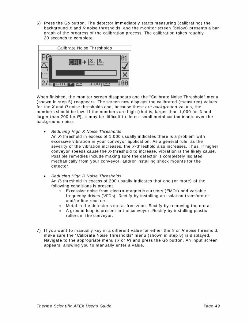
6) Press the Go button. The detector immediately starts measuring (calibrating) the background X and R noise thresholds, and the monitor screen (below) presents a bar graph of the progress of the calibration process. The calibration takes roughly 20 seconds to complete.
Calibrate Noise Thresholds
When finished, the monitor screen disappears and the “Calibrate Noise Threshold” menu (shown in step 5) reappears. The screen now displays the calibrated (measured) values for the X and R noise thresholds and, because these are background values, the numbers should be low. If the numbers are high (that is, larger than 1,000 for X and larger than 200 for R), it may be difficult to detect small metal contaminants over the background noise.
• Reducing High X Noise Thresholds An X-threshold in excess of 1,000 usually indicates there is a problem with excessive vibration in your conveyor application. As a general rule, as the severity of the vibration increases, the X-threshold also increases. Thus, if higher conveyor speeds cause the X-threshold to increase, vibration is the likely cause. Possible remedies include making sure the detector is completely isolated mechanically from your conveyor, and/or installing shock mounts for the detector.
• Reducing High R Noise Thresholds
An R-threshold in excess of 200 usually indicates that one (or more) of the following conditions is present.
o Excessive noise from electro-magnetic currents (EMCs) and variable frequency drives (VFDs). Rectify by installing an isolation transformer and/or line reactors.
o Metal in the detector’s metal-free zone. Rectify by removing the metal. o A ground loop is present in the conveyor. Rectify by installing plastic
rollers in the conveyor. 7) If you want to manually key in a different value for either the X or R noise threshold,
make sure the “Calibrate Noise Thresholds” menu (shown in step 5) is displayed. Navigate to the appropriate menu (X or R) and press the Go button. An input screen appears, allowing you to manually enter a value.
Page 50 Thermo Scientific APEX User’s Guide
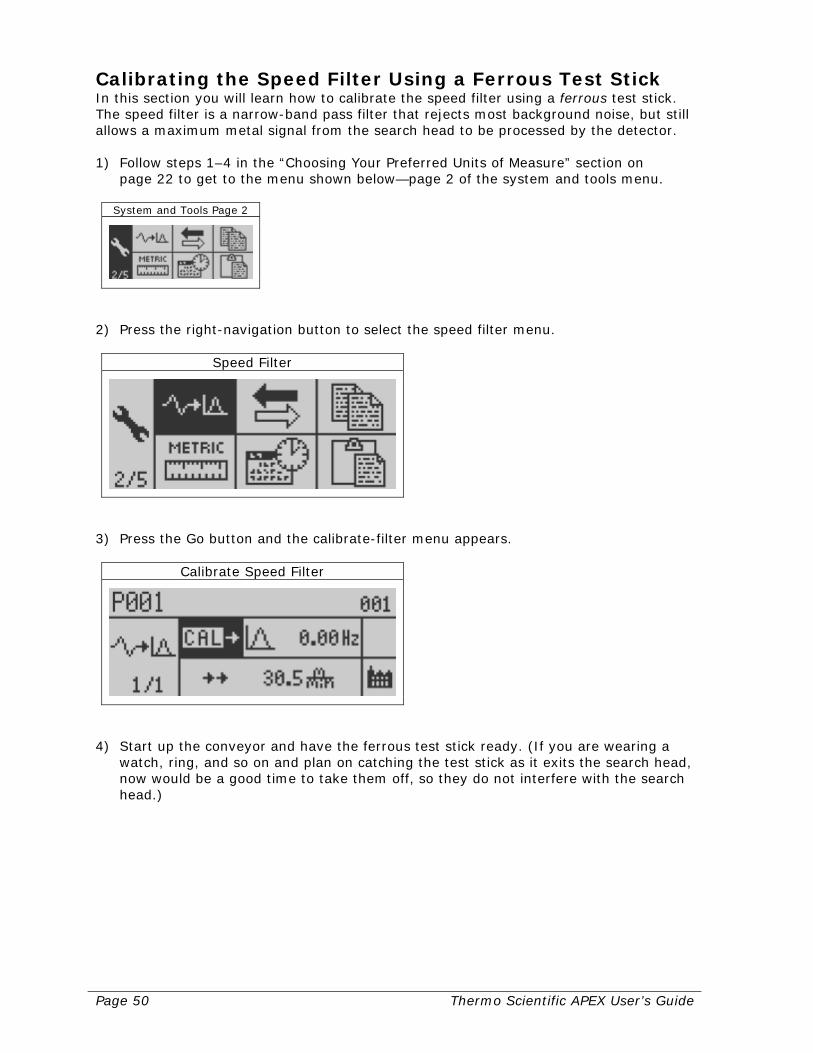
Calibrating the Speed Filter Using a Ferrous Test Stick In this section you will learn how to calibrate the speed filter using a ferrous test stick. The speed filter is a narrow-band pass filter that rejects most background noise, but still allows a maximum metal signal from the search head to be processed by the detector. 1) Follow steps 1–4 in the “Choosing Your Preferred Units of Measure” section on
page 22 to get to the menu shown below—page 2 of the system and tools menu.
System and Tools Page 2
2) Press the right-navigation button to select the speed filter menu.
Speed Filter
3) Press the Go button and the calibrate-filter menu appears.
Calibrate Speed Filter
4) Start up the conveyor and have the ferrous test stick ready. (If you are wearing a
watch, ring, and so on and plan on catching the test stick as it exits the search head, now would be a good time to take them off, so they do not interfere with the search head.)
Thermo Scientific APEX User’s Guide Page 51
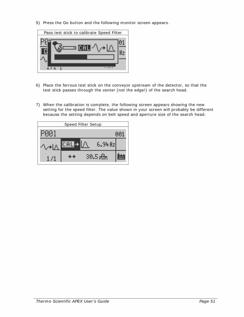
5) Press the Go button and the following monitor screen appears.
Pass test stick to calibrate Speed Filter
6) Place the ferrous test stick on the conveyor upstream of the detector, so that the
test stick passes through the center (not the edge!) of the search head. 7) When the calibration is complete, the following screen appears showing the new
setting for the speed filter. The value shown in your screen will probably be different because the setting depends on belt speed and aperture size of the search head.
Speed Filter Setup

Page 52 Thermo Scientific APEX User’s Guide
Establishing Basic Product Parameters Before putting your detector into service, you must have it learn how to identify your uncontaminated product. This is done using the detector’s full-product calibration function, which sets the following basic parameters for your product.
• Frequency and gain
• Phase-angle setting
• Detect level
• AuditCheck parameters, if applicable Setting Frequency and Gain to High Before doing a full-product calibration, it is best to set the detector’s frequency and gain settings to high. To do this, follow the instructions below. 1) Make sure the Main Menu is displayed.
Product Name
Or, like this when IXR is enabled.
Product Name
(continued…)

Thermo Scientific APEX User’s Guide Page 53
2) Navigate to the frequency and gain menu and make sure it is highlighted.
Frequency and Gain
Or, like this when IXR is enabled.
Frequency and Gain
3) Press the Go button and page 1 of the frequency and gain menu appears.
Frequency, Gain & Inhibit
4) Press the right-navigation button to highlight the gain menu.
Low/High Gain

Page 54 Thermo Scientific APEX User’s Guide
5) Make sure a checkmark is showing next to the high-gain icon, which looks like this.
High-gain icon
Note: If the checkmark is next to the low-gain icon, press the Go button to select the high-gain setting. 6) Press the Back button to save your setting and return to page 1 of the frequency and
gain menu.
Frequency, Gain & Inhibit
7) Navigate to the frequency menu.
Low/High Frequency
8) Make sure a checkmark is showing next to the high-frequency icon, which looks like
this.
High-frequency icon
Note: If the checkmark is next to the low-frequency icon, press the Go button to select the high-frequency setting. 9) Press the Back button repeatedly to save your settings, exit the menu, and return to
the Main Menu.
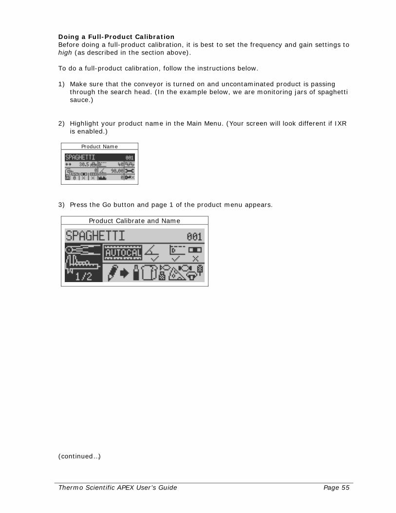
Thermo Scientific APEX User’s Guide Page 55
Doing a Full-Product Calibration Before doing a full-product calibration, it is best to set the frequency and gain settings to high (as described in the section above). To do a full-product calibration, follow the instructions below. 1) Make sure that the conveyor is turned on and uncontaminated product is passing
through the search head. (In the example below, we are monitoring jars of spaghetti sauce.)
2) Highlight your product name in the Main Menu. (Your screen will look different if IXR
is enabled.)
Product Name
3) Press the Go button and page 1 of the product menu appears.
Product Calibrate and Name
(continued…)
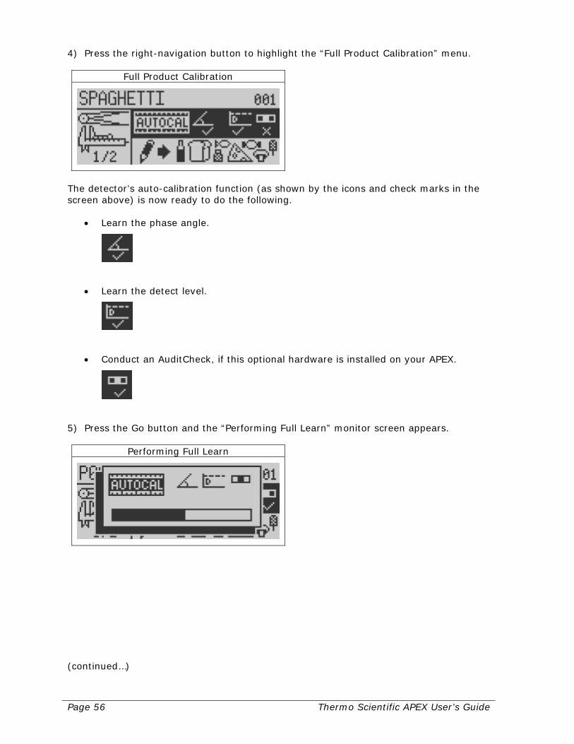
Page 56 Thermo Scientific APEX User’s Guide
4) Press the right-navigation button to highlight the “Full Product Calibration” menu.
Full Product Calibration
The detector’s auto-calibration function (as shown by the icons and check marks in the screen above) is now ready to do the following.
• Learn the phase angle.
• Learn the detect level.
• Conduct an AuditCheck, if this optional hardware is installed on your APEX.
5) Press the Go button and the “Performing Full Learn” monitor screen appears.
Performing Full Learn
(continued…)

Thermo Scientific APEX User’s Guide Page 57
6) When the calibration is complete, the detector displays the Main Menu, which should now look something like this. (Your screen will look different if IXR is enabled.)
Product Name
7) Sometimes, however, the high-frequency and high gain settings are too sensitive,
which saturates the detector’s circuit. When this occurs, the APEX halts the calibration and displays a screen (see below) showing the next-best option—the high-frequency/low gain option. a. High Frequency/Low Gain Option
High Frequency, Low Gain
b. Press the Go button to restart the full product calibration. If this setting is too
sensitive, the following screen appears—the low frequency/high gain option. c. Low Frequency/High Gain Option
Low Frequency, High Gain
Please note that if the frequency is changed, the APEX must relearn the X and R noise thresholds for optimal performance. The APEX software will take you to page 2 of the frequency and gain menu. Follow the directions on page 166 to calibrate the X and R noise thresholds. Then return to the full calibration and continue.
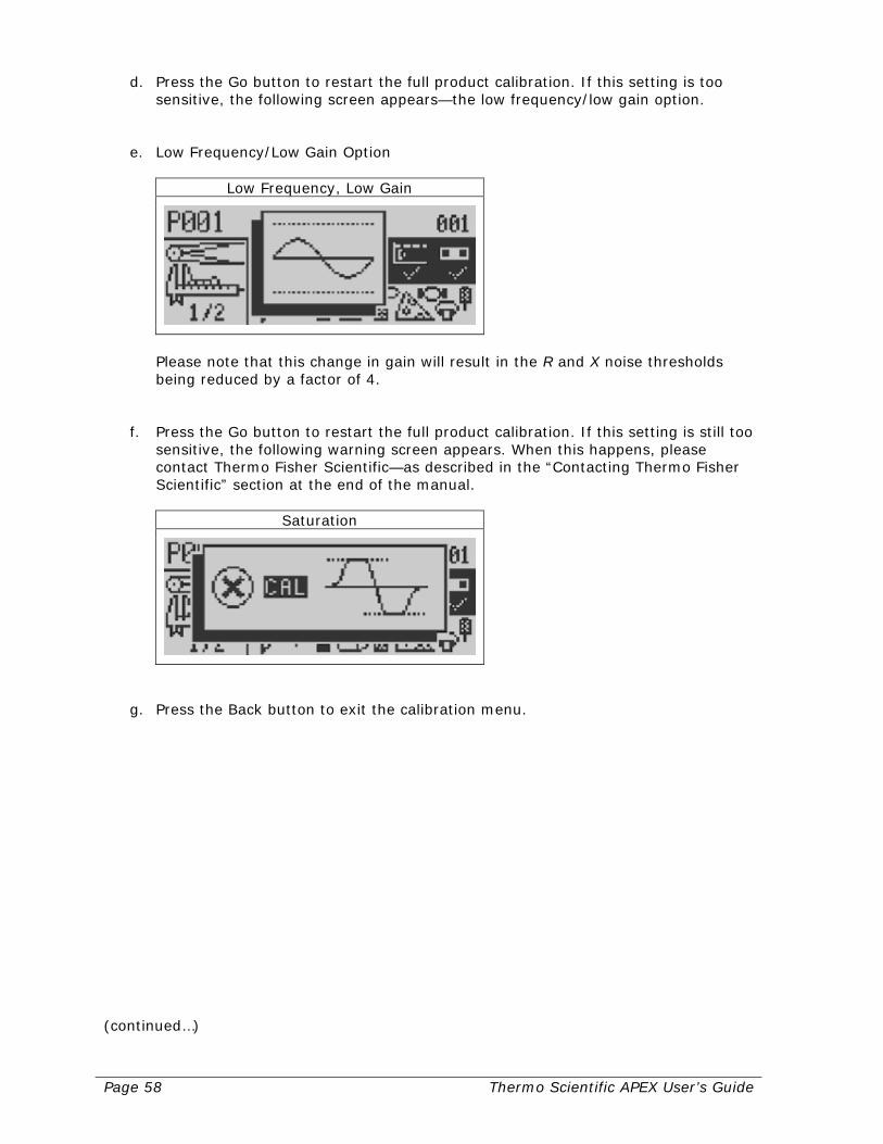
Page 58 Thermo Scientific APEX User’s Guide
d. Press the Go button to restart the full product calibration. If this setting is too sensitive, the following screen appears—the low frequency/low gain option.
e. Low Frequency/Low Gain Option
Low Frequency, Low Gain
Please note that this change in gain will result in the R and X noise thresholds being reduced by a factor of 4.
f. Press the Go button to restart the full product calibration. If this setting is still too
sensitive, the following warning screen appears. When this happens, please contact Thermo Fisher Scientific—as described in the “Contacting Thermo Fisher Scientific” section at the end of the manual.
Saturation
g. Press the Back button to exit the calibration menu.
(continued…)

Thermo Scientific APEX User’s Guide Page 59
8) When the auto-calibration function is finished, the detector displays the Main Menu screen, which should now look something like this. (Your screen will look different if IXR is enabled.)
Product Name
Notice that, in our example, the auto-calibration function has learned the following basic parameters for our uncontaminated product (in our example, jars of spaghetti sauce).
• Detect level = 53
• Phase angle = 2.24
What the Main Menu Screen Is Telling You The Main Menu screen is now telling you that, once the detector is monitoring your product stream, any unit of contaminated product that exceeds the detect level of 53, will be rejected. And, because the phase angle is 2.24 degrees, the detector is monitoring a wet product (in our example, jars of spaghetti sauce).
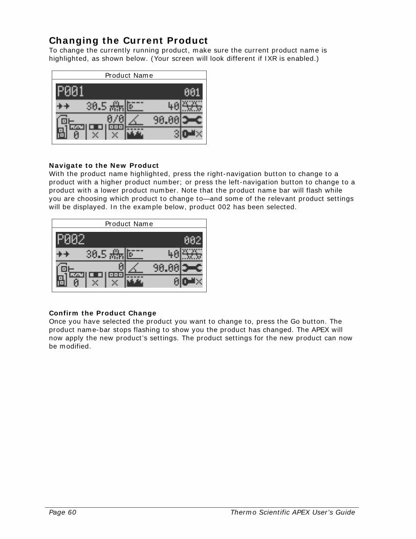
Page 60 Thermo Scientific APEX User’s Guide
Changing the Current Product To change the currently running product, make sure the current product name is highlighted, as shown below. (Your screen will look different if IXR is enabled.)
Product Name
Navigate to the New Product With the product name highlighted, press the right-navigation button to change to a product with a higher product number; or press the left-navigation button to change to a product with a lower product number. Note that the product name bar will flash while you are choosing which product to change to—and some of the relevant product settings will be displayed. In the example below, product 002 has been selected.
Product Name
Confirm the Product Change Once you have selected the product you want to change to, press the Go button. The product name-bar stops flashing to show you the product has changed. The APEX will now apply the new product’s settings. The product settings for the new product can now be modified.
Thermo Scientific APEX User’s Guide Page 61
Set-Up Check List for Conveyor Applications This section lists the parameters you have already set (by following the instructions from the start of the “Setting Up Conveyor Applications” section up to this point in the manual). This section also lists additional parameters you may want to set up to get your particular conveyor application running to your satisfaction.
Parameters You Have Already Set Up Listed below are the parameters you have already set up for a typical conveyor application. Product Parameters
• Product name • Pack length • No-pack distance • Pack gap
Conveyor and Photo-Eye Parameters
• Conveyor belt-speed • Photo-eye-to-detector distance • Polarity of the photo-eye input • Photo registration for product rejects
Reject Parameters
• Distance to the reject device • Signal duration for the reject device
Contaminant-Detection Parameters (Set by the Detector’s Calibrate Functions)
• X and R noise thresholds • Speed-filter setting • Detect level • Phase-angle setting

Page 62 Thermo Scientific APEX User’s Guide
Additional Parameters You May Want to Set Up Listed below are additional parameters you may want to set up to get your particular conveyor application running to your satisfaction. Belt-Speed-Encoder Function If your conveyor has a speed encoder, this function allows the conveyor speed parameter to be set automatically. For more details, see page 124. Bin-Full Notification If your reject bin is monitored by a photo-eye, this function allows you to be notified (or the conveyor stopped), when the reject bin is full. For more details, see page 217. Reject-Confirm Function If you have an additional photo eye to confirm that a reject has, indeed, occurred, this function notifies you if the reject does not occur. For more details, see page 137. Warnings, Alarms, and Faults (WAFs) Many of the detectors functions provide a warning, alarm, or fault when a condition needing your attention occurs. This menu—in conjunction with the appropriate hardwired external device—allows this to happen. For more details, see page 214. Quality Test A Quality Test allows you to verify that the detector is working properly, especially when testing products over long periods of time. The Quality Test is a manual, not an automatic, test. For more details, see page 196. AuditCheck If the optional AuditCheck equipment is installed on your search head, the AuditCheck function allows you to verify that the detector is working properly, especially when testing products over long periods of time. The AuditCheck tests occur automatically, while product is running, at time intervals you specify. For more details, see page 206. Phase Tracking The phase-tracking function allows the APEX to automatically adjust the product phase for small variations in phase over long periods of time, especially when testing wet products (where the phase angle is sensitive to product temperature). For more details, see page 153. Copying and Pasting Product Parameters This function is particularly useful when you are testing multiple products. You can save considerable amounts of time and effort using the copy and paste functions, because you do not need to re-enter the product parameters for each product, re-run the calibrations, and so on. For more details, see page 173.
Thermo Scientific APEX User’s Guide Page 63
Setting Up Gravity-Feed Applications This section assumes you have already completed the electrical and mechanical installations for your detector. If not, see pages 283 (for electrical set-up instructions) and 299 (for mechanical set-up instructions). The purpose of this section is to present you with a brief tutorial, allowing you to get your gravity-feed application up and running as quickly as possible. Here is an outline of what you will be learning. If you are already familiar with some of the information covered, you can always skip ahead to the next section. Understanding Your Detector In this section you will learn how to…
• Use the detector’s display panel. • Navigate the detector’s menus and sub-menus. • Set up global parameters for the detector. • Key in a name for your product.
Setting Reject Parameters In this section you will learn how to…
• Key in the reject-delay time. • Key in the reject-duration time.
Setting Contaminant-Detection Parameters In this section you will learn how to…
• Establish a noise threshold with no product present in the duct. • Select the appropriate setting for the speed filter. • Establish basic product parameters (detect level and phase-angle).
Understanding Technical Terms If you encounter a technical term you do not understand in these sections, please refer to the Glossary on page 393. For example, the word “product” means anything the detector is testing for the presence of metal contaminants, and is a word you will encounter often in this manual. Let’s get started!

Page 64 Thermo Scientific APEX User’s Guide
Understanding Your Detector In order to minimize the length of this already lengthy manual, we are not going to repeat information here that has already been covered elsewhere in the manual—and we hope you agree this is a wise choice. Please start at page 1 of the “Getting Started” section and read all the way through to the end of the “Naming the Product” section on page 26. When you have finished reading these sections you will know how to do the following.
• Use the detector’s display panel. • Navigate the detector’s menus and sub-menus. • Set up global parameters for the detector. • Key in a name for your product.
The Next Step Now that detour is over, welcome back! You are now ready to set up the specific parameters you will need to run your gravity-feed application. Read on for more details.
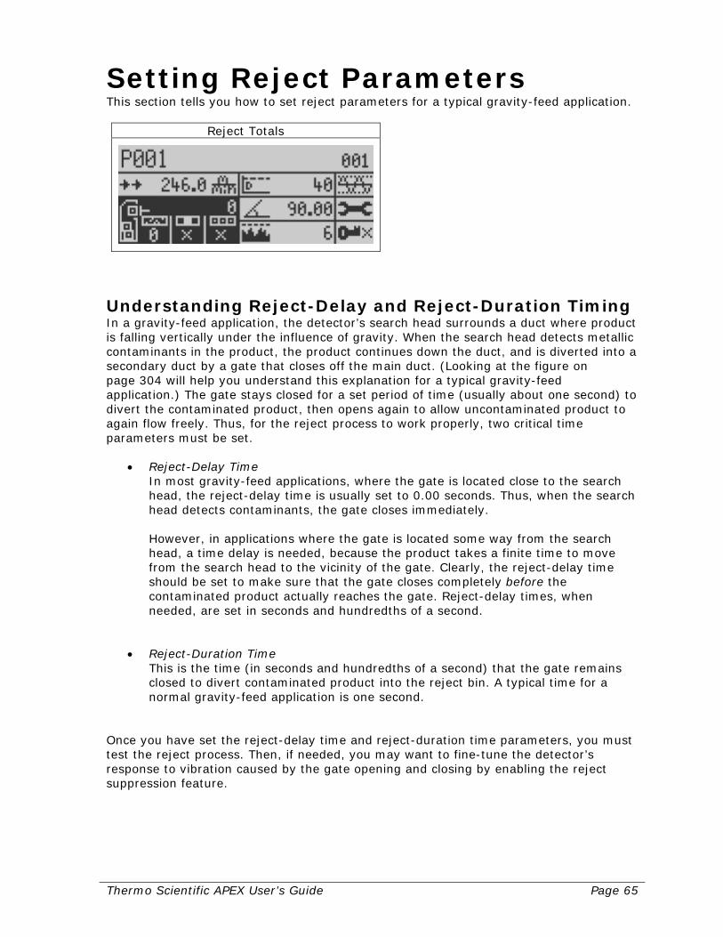
Thermo Scientific APEX User’s Guide Page 65
Setting Reject Parameters This section tells you how to set reject parameters for a typical gravity-feed application.
Reject Totals
Understanding Reject-Delay and Reject-Duration Timing In a gravity-feed application, the detector’s search head surrounds a duct where product is falling vertically under the influence of gravity. When the search head detects metallic contaminants in the product, the product continues down the duct, and is diverted into a secondary duct by a gate that closes off the main duct. (Looking at the figure on page 304 will help you understand this explanation for a typical gravity-feed application.) The gate stays closed for a set period of time (usually about one second) to divert the contaminated product, then opens again to allow uncontaminated product to again flow freely. Thus, for the reject process to work properly, two critical time parameters must be set.
• Reject-Delay Time In most gravity-feed applications, where the gate is located close to the search head, the reject-delay time is usually set to 0.00 seconds. Thus, when the search head detects contaminants, the gate closes immediately. However, in applications where the gate is located some way from the search head, a time delay is needed, because the product takes a finite time to move from the search head to the vicinity of the gate. Clearly, the reject-delay time should be set to make sure that the gate closes completely before the contaminated product actually reaches the gate. Reject-delay times, when needed, are set in seconds and hundredths of a second.
• Reject-Duration Time
This is the time (in seconds and hundredths of a second) that the gate remains closed to divert contaminated product into the reject bin. A typical time for a normal gravity-feed application is one second.
Once you have set the reject-delay time and reject-duration time parameters, you must test the reject process. Then, if needed, you may want to fine-tune the detector’s response to vibration caused by the gate opening and closing by enabling the reject suppression feature.

Page 66 Thermo Scientific APEX User’s Guide
Setting the Reject-Delay Time To set the reject-delay time, do the following. 1) From the Main Menu navigate to the rejects menu.
Reject Totals
2) Press the Go button and page 1 of the rejects menu appears.
Reject 1 Distance and Duration
3) Navigate to the reject-1 distance/delay menu shown below.
Reject 1 Distance/Delay
4) Press the Go button and the reject-1 distance/delay input screen appears. Key in an
appropriate value for reject-1 distance/delay. For a typical gravity-feed application, key in a value of 0.00 seconds. This allows the reject gate to close immediately, when metallic contaminants are detected.
Reject 1 Distance/Delay

Thermo Scientific APEX User’s Guide Page 67
5) Press the Go button to save your setting. 6) Press the Back button repeatedly to return to the Main Menu.
Setting the Reject-Duration Time To set the reject-duration time, do the following. 1) From the Main Menu navigate to the rejects menu.
Reject Totals
2) Press the Go button and page 1 of the rejects menu appears.
Reject 1…
3) Navigate to the reject-1 duration menu shown below.
Reject 1 Duration
(continued…)
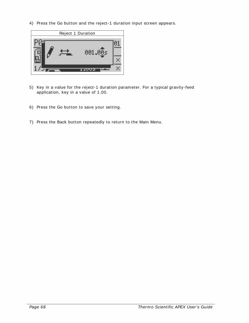
Page 68 Thermo Scientific APEX User’s Guide
4) Press the Go button and the reject-1 duration input screen appears.
Reject 1 Duration
5) Key in a value for the reject-1 duration parameter. For a typical gravity-feed
application, key in a value of 1.00. 6) Press the Go button to save your setting. 7) Press the Back button repeatedly to return to the Main Menu.

Thermo Scientific APEX User’s Guide Page 69
Setting Contaminant-Detection Parameters This section assumes you have followed all the instructions from the start of the “Setting Up Gravity-Feed Applications” to this point. The reason for this is that, before you can calibrate your detector, the parameters described above must already have been set. This section tells you how to do the following.
• Set up a monitoring baseline for the detector by calibrating the X and R noise thresholds, which must be done when no product is present in the duct.
• Select the appropriate value for the speed filter. • Establish basic product parameters (detect level and phase-angle).
Once you have finished this section, your detector will be set up and ready to go to work monitoring your product stream for the presence of metallic contaminants.
Establishing a Baseline with No Product Present Before you can establish a monitoring baseline (that is, establish a background-noise level) for the X and R thresholds (the parameters that allow the detector to identify metal contaminants), you must make sure no product is falling through the duct. 1) Make sure the Main Menu is displayed.
Product Name
2) Navigate to the frequency and gain menu.
Frequency and Gain

Page 70 Thermo Scientific APEX User’s Guide
3) Press the Go button and page 1 of the “Frequency, Gain & Inhibit” menu appears.
Frequency, Gain & Inhibit
4) Press the down-navigation key to select page 2 of the frequency and gain menu.
Detection level and Noise
5) Navigate to the “Calibrate Noise Thresholds” menu. (Note: The background of the
calibrate function is now highlighted in black.)
Calibrate Noise Thresholds
(continued…)

Thermo Scientific APEX User’s Guide Page 71
6) Press the Go button. The detector immediately starts measuring (calibrating) the background X and R noise thresholds, and the monitor screen (below) presents a bar graph of the progress of the calibration process. The calibration takes roughly 20 seconds to complete.
Calibrate Noise Thresholds
When finished, the monitor screen disappears and the “Calibrate Noise Threshold” menu (shown in step 5) reappears. The screen now displays the calibrated (measured) values for the X and R noise thresholds and, because these are background values, the numbers should be low. If the numbers are high, it may be difficult to detect small metal contaminants over the background noise.
• Reducing High X Noise Thresholds An X-threshold in excess of 1,000 usually indicates there is a problem with excessive vibration in your application. As a general rule, as the severity of the vibration increases, the X-threshold also increases. Possible remedies include making sure the detector is completely isolated mechanically from the surrounding duct, and/or installing shock mounts for the detector.
• Reducing High R Noise Thresholds
An R-threshold in excess of 200 usually indicates that one (or more) of the following conditions is present.
o Excessive noise from electro-magnetic currents (EMCs) and variable frequency drives (VFDs). Rectify by installing an isolation transformer and/or line reactors.
o Metal in the detector’s metal-free zone. Rectify by removing the metal. 7) If you want to manually key in a different value for either the X or R noise threshold,
make sure the “Calibrate Noise Thresholds” menu (shown in step 5) is displayed. Navigate to the appropriate menu (X or R) and press the Go button. An input screen appears, allowing you to manually enter a value.
X Threshold
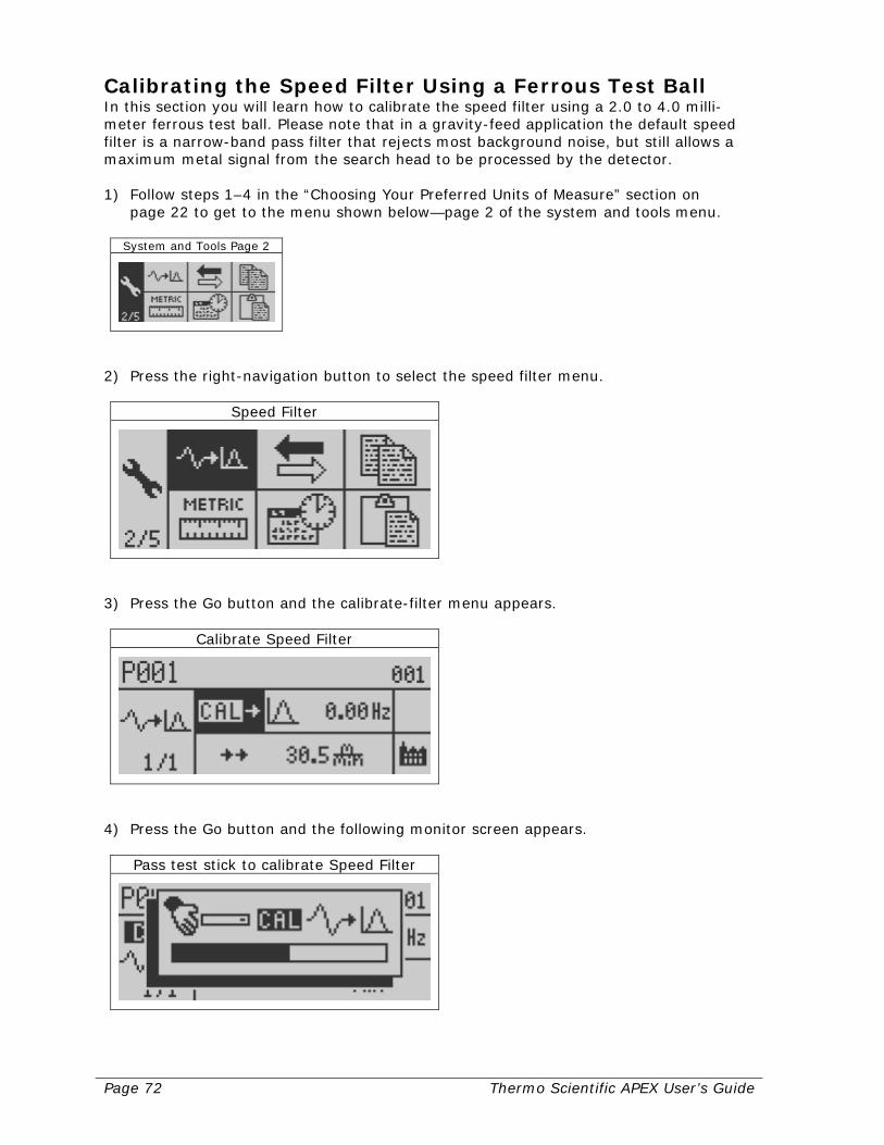
Page 72 Thermo Scientific APEX User’s Guide
Calibrating the Speed Filter Using a Ferrous Test Ball In this section you will learn how to calibrate the speed filter using a 2.0 to 4.0 milli-meter ferrous test ball. Please note that in a gravity-feed application the default speed filter is a narrow-band pass filter that rejects most background noise, but still allows a maximum metal signal from the search head to be processed by the detector. 1) Follow steps 1–4 in the “Choosing Your Preferred Units of Measure” section on
page 22 to get to the menu shown below—page 2 of the system and tools menu.
System and Tools Page 2
2) Press the right-navigation button to select the speed filter menu.
Speed Filter
3) Press the Go button and the calibrate-filter menu appears.
Calibrate Speed Filter
4) Press the Go button and the following monitor screen appears.
Pass test stick to calibrate Speed Filter
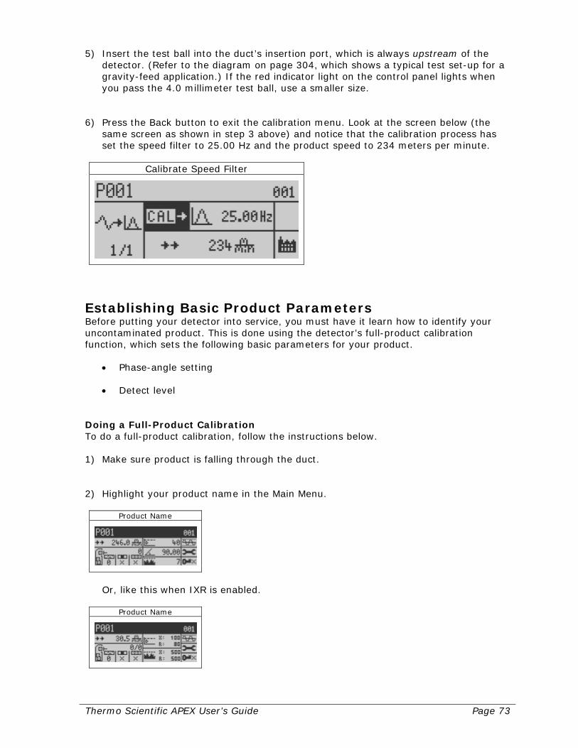
Thermo Scientific APEX User’s Guide Page 73
5) Insert the test ball into the duct’s insertion port, which is always upstream of the detector. (Refer to the diagram on page 304, which shows a typical test set-up for a gravity-feed application.) If the red indicator light on the control panel lights when you pass the 4.0 millimeter test ball, use a smaller size.
6) Press the Back button to exit the calibration menu. Look at the screen below (the
same screen as shown in step 3 above) and notice that the calibration process has set the speed filter to 25.00 Hz and the product speed to 234 meters per minute.
Calibrate Speed Filter
Establishing Basic Product Parameters Before putting your detector into service, you must have it learn how to identify your uncontaminated product. This is done using the detector’s full-product calibration function, which sets the following basic parameters for your product.
• Phase-angle setting
• Detect level Doing a Full-Product Calibration To do a full-product calibration, follow the instructions below. 1) Make sure product is falling through the duct. 2) Highlight your product name in the Main Menu.
Product Name
Or, like this when IXR is enabled.
Product Name

Page 74 Thermo Scientific APEX User’s Guide
3) Press the Go button and page 1 of the product menu appears.
Product Calibrate and Name
4) Press the right-navigation button to highlight the “Full Product Calibration” menu.
Full Product Calibration
The detector’s auto-calibration function (as shown by the symbols and check marks in the screen above) is now ready to do the following.
• Learn the phase angle
• Learn the detect level
• Conduct an AuditCheck, if this optional hardware is installed on your APEX.
(continued…)
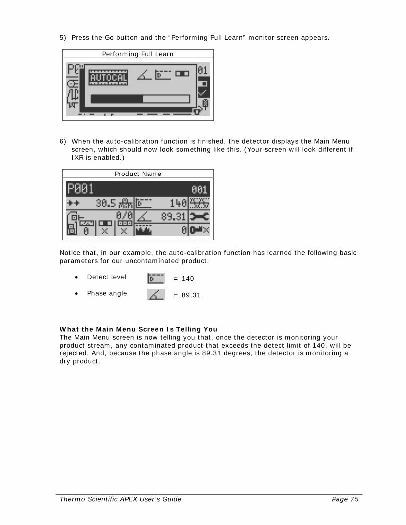
Thermo Scientific APEX User’s Guide Page 75
5) Press the Go button and the “Performing Full Learn” monitor screen appears.
Performing Full Learn
6) When the auto-calibration function is finished, the detector displays the Main Menu
screen, which should now look something like this. (Your screen will look different if IXR is enabled.)
Product Name
Notice that, in our example, the auto-calibration function has learned the following basic parameters for our uncontaminated product.
• Detect level = 140
• Phase angle = 89.31
What the Main Menu Screen Is Telling You The Main Menu screen is now telling you that, once the detector is monitoring your product stream, any contaminated product that exceeds the detect limit of 140, will be rejected. And, because the phase angle is 89.31 degrees, the detector is monitoring a dry product.
Page 76 Thermo Scientific APEX User’s Guide
Set-Up Check List for Gravity-Feed Applications This section lists the parameters you have already set (by following the instructions from the start of the “Setting Up Gravity-Feed Applications” section up to this point in the manual). This section also lists additional parameters you may want to set up to get your particular gravity-feed application running to your satisfaction.
Parameters You Have Already Set Up Listed below are the parameters you have already set up for a typical gravity-feed application. Product Parameters
• Product name Reject Parameters
• Reject-delay time • Reject-duration time
Contaminant-Detection Parameters (Set by the Detector’s Calibrate Functions)
• X and R noise thresholds • Speed-filter setting • Detect level • Phase-angle setting

Thermo Scientific APEX User’s Guide Page 77
Additional Parameters You May Want to Set Up Listed below are additional parameters you may want to set up to get your particular gravity-feed application running to your satisfaction. Suppression-Time and Suppression-Amplitude Functions These functions are used to prevent vibration from the gate interfering with the search head. For more details, see page 130. Reject-Confirm Function If your gate is equipped with a position detector, this function allows the detector to confirm that, during a reject cycle, the gate has properly completed both the “open” and “close” phases of the reject cycle. In addition, if a gate failure occurs, the detector can stop the flow of product, or notify you that a gate failure has occurred—for example, because the air supply to the gate has failed, or product has built up on the gate or surrounding duct-work. For more details, see page 137. Warnings, Alarms, and Faults (WAFs) Many of the detector’s functions provide a warning, alarm, or fault when a condition needing your attention occurs. This menu—in conjunction with the appropriate hardwired external device—allows this to happen. For more details, see page 214. Copying and Pasting Product Parameters This function is particularly useful when you are testing multiple products. You can save considerable amounts of time and effort using the copy and paste functions, because you do not need to re-enter the product parameters for each product, re-run the calibrations, and so on. For more details, see page 173.

Page 78 Thermo Scientific APEX User’s Guide
Thermo Scientific APEX User’s Guide Page 79
Setting Up Pipeline Applications This section assumes you have already completed the electrical and mechanical installations for your detector. If not, see pages 283 (for electrical set-up instructions) and 307 (for mechanical set-up instructions). The purpose of this section is to present you with a brief tutorial, allowing you to get your pipeline application up and running as quickly as possible. Here is an outline of what you will be learning. If you are already familiar with some of the information covered, you can always skip ahead to the next section. Understanding Your Detector In this section you will learn how to…
• Use the detector’s display panel. • Navigate the detector’s menus and sub-menus. • Set up global parameters for the detector. • Key in a name for your product.
Setting Reject Parameters In this section you will learn how to…
• Key in the reject-delay time. • Key in the reject-duration time.
Setting Contaminant-Detection Parameters In this section you will learn how to…
• Establish a noise threshold with no product present in the pipe. • Select the appropriate setting for the speed filter. • Establish basic product parameters (detect level and phase-angle).
Understanding Technical Terms If you encounter a technical term you do not understand in these sections, please refer to the Glossary on page 393. For example, the word “product” means anything the detector is testing for the presence of metal contaminants, and is a word you will encounter often in this manual. Let’s get started!

Page 80 Thermo Scientific APEX User’s Guide
Understanding Your Detector In order to minimize the length of this already lengthy manual, we are not going to repeat information here that has already been covered elsewhere in the manual—and we hope you agree this is a wise choice. Please start at page 1 of the “Getting Started” section and read all the way through to the end of the “Naming the Product” section on page 26. When you have finished reading these sections you will know how to do the following.
• Use the detector’s display panel. • Navigate the detector’s menus and sub-menus. • Set up global parameters for the detector. • Key in a name for your product.
The Next Step Now that detour is over, welcome back! You are now ready to set up the specific parameters you will need to run your pipeline application. Read on for more details.
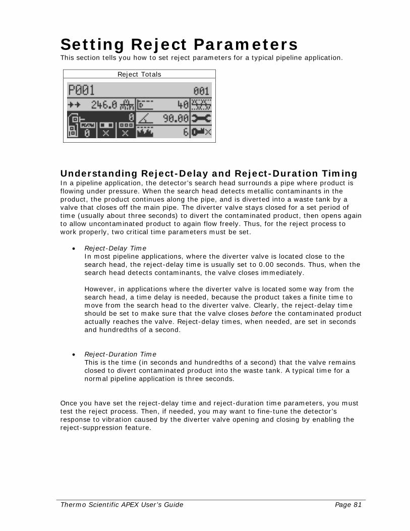
Thermo Scientific APEX User’s Guide Page 81
Setting Reject Parameters This section tells you how to set reject parameters for a typical pipeline application.
Reject Totals
Understanding Reject-Delay and Reject-Duration Timing In a pipeline application, the detector’s search head surrounds a pipe where product is flowing under pressure. When the search head detects metallic contaminants in the product, the product continues along the pipe, and is diverted into a waste tank by a valve that closes off the main pipe. The diverter valve stays closed for a set period of time (usually about three seconds) to divert the contaminated product, then opens again to allow uncontaminated product to again flow freely. Thus, for the reject process to work properly, two critical time parameters must be set.
• Reject-Delay Time In most pipeline applications, where the diverter valve is located close to the search head, the reject-delay time is usually set to 0.00 seconds. Thus, when the search head detects contaminants, the valve closes immediately. However, in applications where the diverter valve is located some way from the search head, a time delay is needed, because the product takes a finite time to move from the search head to the diverter valve. Clearly, the reject-delay time should be set to make sure that the valve closes before the contaminated product actually reaches the valve. Reject-delay times, when needed, are set in seconds and hundredths of a second.
• Reject-Duration Time
This is the time (in seconds and hundredths of a second) that the valve remains closed to divert contaminated product into the waste tank. A typical time for a normal pipeline application is three seconds.
Once you have set the reject-delay time and reject-duration time parameters, you must test the reject process. Then, if needed, you may want to fine-tune the detector’s response to vibration caused by the diverter valve opening and closing by enabling the reject-suppression feature.
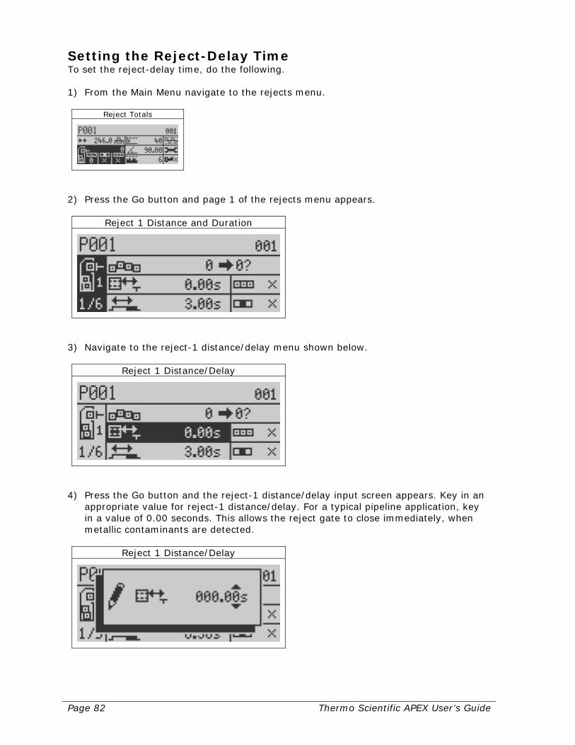
Page 82 Thermo Scientific APEX User’s Guide
Setting the Reject-Delay Time To set the reject-delay time, do the following. 1) From the Main Menu navigate to the rejects menu.
Reject Totals
2) Press the Go button and page 1 of the rejects menu appears.
Reject 1 Distance and Duration
3) Navigate to the reject-1 distance/delay menu shown below.
Reject 1 Distance/Delay
4) Press the Go button and the reject-1 distance/delay input screen appears. Key in an
appropriate value for reject-1 distance/delay. For a typical pipeline application, key in a value of 0.00 seconds. This allows the reject gate to close immediately, when metallic contaminants are detected.
Reject 1 Distance/Delay
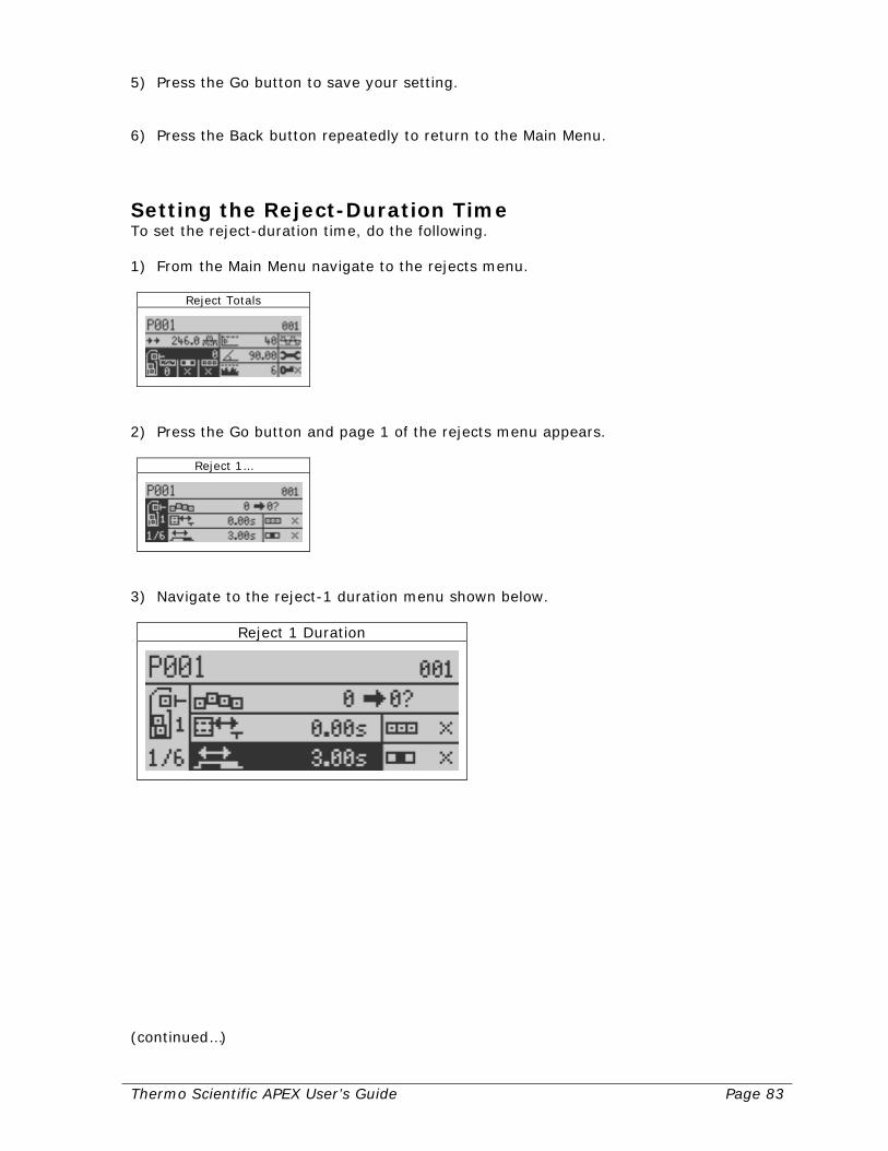
Thermo Scientific APEX User’s Guide Page 83
5) Press the Go button to save your setting. 6) Press the Back button repeatedly to return to the Main Menu.
Setting the Reject-Duration Time To set the reject-duration time, do the following. 1) From the Main Menu navigate to the rejects menu.
Reject Totals
2) Press the Go button and page 1 of the rejects menu appears.
Reject 1…
3) Navigate to the reject-1 duration menu shown below.
Reject 1 Duration
(continued…)

Page 84 Thermo Scientific APEX User’s Guide
4) Press the Go button and the reject-1 duration input screen appears.
Reject 1 Duration
5) Key in a value for the reject-1 duration parameter. For a typical pipeline application,
key in a value of 3.00 seconds. 6) Press the Go button to save your setting. 7) Press the Back button repeatedly to return to the Main Menu.

Thermo Scientific APEX User’s Guide Page 85
Setting Contaminant-Detection Parameters This section assumes you have followed all the instructions from the start of the “Setting Up Pipeline Applications” to this point. The reason for this is that, before you can calibrate your detector, the parameters described above must already have been set. This section tells you how to do the following.
• Set up a monitoring baseline for the detector by calibrating the X and R noise thresholds, which must be done when no product is present in the pipe.
• Select the appropriate value for the speed filter. • Establish basic product parameters (detect level and phase-angle).
Once you have finished this section, your detector will be set up and ready to go to work monitoring your product stream for the presence of metallic contaminants.
Establishing a Baseline with No Product Present Before you can establish a monitoring baseline (that is, establish a background-noise level) for the X and R thresholds (the parameters that allow the detector to identify metal contaminants), you must make sure no product is flowing through the pipe. 1) Make sure the Main Menu is displayed.
Product Name
2) Navigate to the frequency and gain menu.
Frequency and Gain

Page 86 Thermo Scientific APEX User’s Guide
3) Press the Go button and page 1 of the “Frequency, Gain & Inhibit” menu appears.
Frequency, Gain & Inhibit
4) Press the down-navigation key to select page 2 of the frequency and gain menu.
Detection level and Noise
5) Navigate to the “Calibrate Noise Thresholds” menu. (Note: The background of the
calibrate function is now highlighted in black.)
Calibrate Noise Thresholds
(continued…)
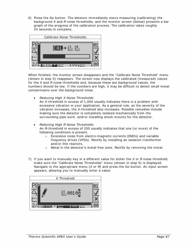
Thermo Scientific APEX User’s Guide Page 87
6) Press the Go button. The detector immediately starts measuring (calibrating) the background X and R noise thresholds, and the monitor screen (below) presents a bar graph of the progress of the calibration process. The calibration takes roughly 20 seconds to complete.
Calibrate Noise Thresholds
When finished, the monitor screen disappears and the “Calibrate Noise Threshold” menu (shown in step 5) reappears. The screen now displays the calibrated (measured) values for the X and R noise thresholds and, because these are background values, the numbers should be low. If the numbers are high, it may be difficult to detect small metal contaminants over the background noise.
• Reducing High X Noise Thresholds An X-threshold in excess of 1,000 usually indicates there is a problem with excessive vibration in your application. As a general rule, as the severity of the vibration increases, the X-threshold also increases. Possible remedies include making sure the detector is completely isolated mechanically from the surrounding pipe work, and/or installing shock mounts for the detector.
• Reducing High R Noise Thresholds
An R-threshold in excess of 200 usually indicates that one (or more) of the following conditions is present.
o Excessive noise from electro-magnetic currents (EMCs) and variable frequency drives (VFDs). Rectify by installing an isolation transformer and/or line reactors.
o Metal in the detector’s metal-free zone. Rectify by removing the metal. 7) If you want to manually key in a different value for either the X or R noise threshold,
make sure the “Calibrate Noise Thresholds” menu (shown in step 5) is displayed. Navigate to the appropriate menu (X or R) and press the Go button. An input screen appears, allowing you to manually enter a value.
X Threshold
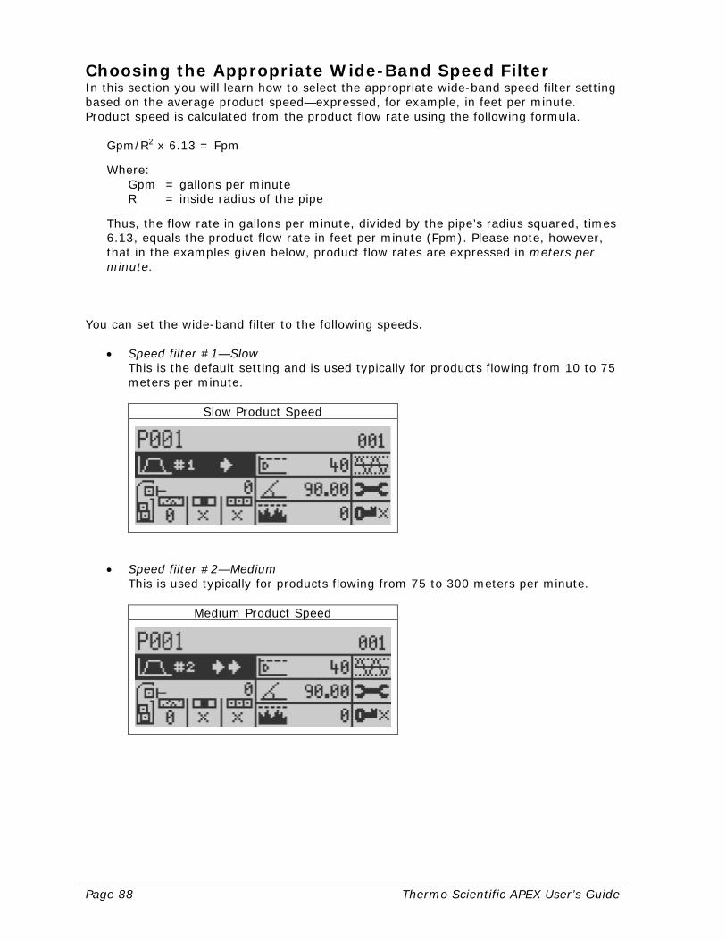
Page 88 Thermo Scientific APEX User’s Guide
Choosing the Appropriate Wide-Band Speed Filter In this section you will learn how to select the appropriate wide-band speed filter setting based on the average product speed—expressed, for example, in feet per minute. Product speed is calculated from the product flow rate using the following formula.
Gpm/R2 x 6.13 = Fpm
Where: Gpm = gallons per minute R = inside radius of the pipe
Thus, the flow rate in gallons per minute, divided by the pipe’s radius squared, times 6.13, equals the product flow rate in feet per minute (Fpm). Please note, however, that in the examples given below, product flow rates are expressed in meters per minute.
You can set the wide-band filter to the following speeds.
• Speed filter #1—Slow This is the default setting and is used typically for products flowing from 10 to 75 meters per minute.
Slow Product Speed
• Speed filter #2—Medium This is used typically for products flowing from 75 to 300 meters per minute.
Medium Product Speed
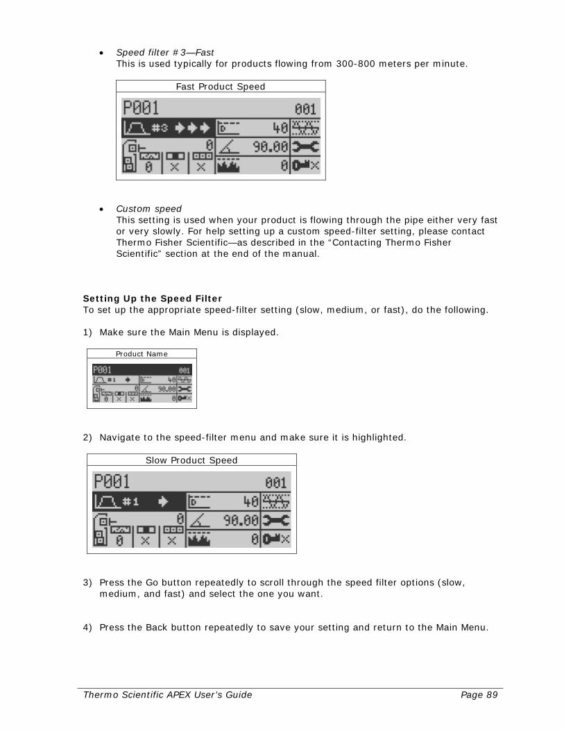
Thermo Scientific APEX User’s Guide Page 89
• Speed filter #3—Fast This is used typically for products flowing from 300-800 meters per minute.
Fast Product Speed
• Custom speed This setting is used when your product is flowing through the pipe either very fast or very slowly. For help setting up a custom speed-filter setting, please contact Thermo Fisher Scientific—as described in the “Contacting Thermo Fisher Scientific” section at the end of the manual.
Setting Up the Speed Filter To set up the appropriate speed-filter setting (slow, medium, or fast), do the following. 1) Make sure the Main Menu is displayed.
Product Name
2) Navigate to the speed-filter menu and make sure it is highlighted.
Slow Product Speed
3) Press the Go button repeatedly to scroll through the speed filter options (slow,
medium, and fast) and select the one you want. 4) Press the Back button repeatedly to save your setting and return to the Main Menu.

Page 90 Thermo Scientific APEX User’s Guide
Establishing Basic Product Parameters Before putting your detector into service, you must have it learn how to identify your uncontaminated product. This is done using the detector’s full-product calibration function, which sets the following basic parameters for your product.
• Phase-angle setting
• Detect level Doing a Full-Product Calibration To do a full-product calibration, follow the instructions below. 1) Make sure product is flowing through the pipe. 2) Highlight your product name in the Main Menu. (Your screen will look different if IXR
is enabled.)
Product Name
3) Press the Go button and page 1 of the product menu appears.
Product Calibrate and Name
(continued…)
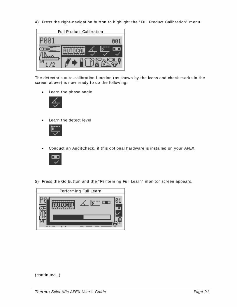
Thermo Scientific APEX User’s Guide Page 91
4) Press the right-navigation button to highlight the “Full Product Calibration” menu.
Full Product Calibration
The detector’s auto-calibration function (as shown by the icons and check marks in the screen above) is now ready to do the following.
• Learn the phase angle
• Learn the detect level
• Conduct an AuditCheck, if this optional hardware is installed on your APEX.
5) Press the Go button and the “Performing Full Learn” monitor screen appears.
Performing Full Learn
(continued…)

Page 92 Thermo Scientific APEX User’s Guide
6) When the auto-calibration function is finished, the detector displays the Main Menu screen, which should now look something like this. (Your screen will look different if IXR is enabled.)
Product Name
Notice that, in our example, the auto-calibration function has learned the following basic parameters for our uncontaminated product.
• Detect level = 202
• Phase angle = 1.46
What the Main Menu Screen Is Telling You The Main Menu screen is now telling you that, once the detector is monitoring your product stream, any contaminated product that exceeds the detect level of 202, will be rejected. And, because the phase angle is 1.46 degrees, the detector is monitoring a wet product.
Thermo Scientific APEX User’s Guide Page 93
Set-Up Check List for Pipeline Applications This section lists the parameters you have already set (by following the instructions from the start of the “Setting Up Pipeline Applications” section up to this point in the manual). This section also lists additional parameters you may want to set up to get your particular pipeline application running to your satisfaction.
Parameters You Have Already Set Up Listed below are the parameters you have already set up for a typical pipeline application. Product Parameters
• Product name Reject Parameters
• Reject-delay time • Reject-duration time
Contaminant-Detection Parameters (Set by the Detector’s Calibrate Functions)
• X and R noise thresholds • Speed-filter setting • Detect level • Phase-angle setting
Page 94 Thermo Scientific APEX User’s Guide
Additional Parameters You May Want to Set Up Listed below are additional parameters you may want to set up to get your particular pipeline application running to your satisfaction. Suppression-Time and Suppression-Amplitude Functions These functions are used to prevent vibration from the diverter valve interfering with the search head. For more details, see page 130. Reject-Confirm Function If your diverter valve is equipped with a position detector, this function allows the detector to confirm that, during a reject cycle, the diverter valve has properly completed both the “open” and “close” phases of the reject cycle. In addition, if the diverter valve fails, the detector can stop the flow of product, or notify you that a failure has occurred—for example, because the air supply to the valve has failed, or miscellaneous residue has clogged the valve. For more details, see page 137. Warnings, Alarms, and Faults (WAFs) Many of the detector’s functions provide a warning, alarm, or fault when a condition needing your attention occurs. This menu—in conjunction with the appropriate hardwired external device—allows this to happen. For more details, see page 214. Copying and Pasting Product Parameters This function is particularly useful when you are testing multiple products. You can save considerable amounts of time and effort using the copy and paste functions, because you do not need to re-enter the product parameters for each product, re-run the calibrations, and so on. For more details, see page 173.

Thermo Scientific APEX User’s Guide Page 95
Setting Up Pharmaceutical (Rx) Applications This section assumes you have already completed the electrical and mechanical installations for your detector. If not, see pages 283 (for electrical set-up instructions) and 299 (for mechanical set-up instructions). The purpose of this section is to present you with a brief tutorial, allowing you to get your pharmaceutical application up and running as quickly as possible. Here is an outline of what you will be learning. If you are already familiar with some of the information covered, you can always skip ahead to the next section. Understanding Your Detector In this section you will learn how to…
• Use the detector’s display panel. • Navigate the detector’s menus and sub-menus. • Set up global parameters for the detector. • Key in a name for your product.
Setting Reject Parameters In this section you will learn how to…
• Key in the reject-delay time. • Key in the reject-duration time.
Setting Contaminant-Detection Parameters In this section you will learn how to…
• Establish a noise threshold with no product present in the chute. • Select the appropriate setting for the speed filter. • Establish basic product parameters (detect level and phase-angle).
Understanding Technical Terms If you encounter a technical term you do not understand in these sections, please refer to the Glossary on page 393. For example, the word “product” means anything the detector is testing for the presence of metal contaminants, and is a word you will encounter often in this manual. Let’s get started!
Page 96 Thermo Scientific APEX User’s Guide
Understanding Your Detector In order to minimize the length of this already lengthy manual, we are not going to repeat information here that has already been covered elsewhere in the manual—and we hope you agree this is a wise choice. Please start at page 1 of the “Getting Started” section and read all the way through to the end of the “Naming the Product” section on page 26. When you have finished reading these sections you will know how to do the following.
• Use the detector’s display panel. • Navigate the detector’s menus and sub-menus. • Set up global parameters for the detector. • Key in a name for your product.
The Next Step Now that detour is over, welcome back! You are now ready to set up the specific parameters you will need to run your pharmaceutical application. Read on for more details.
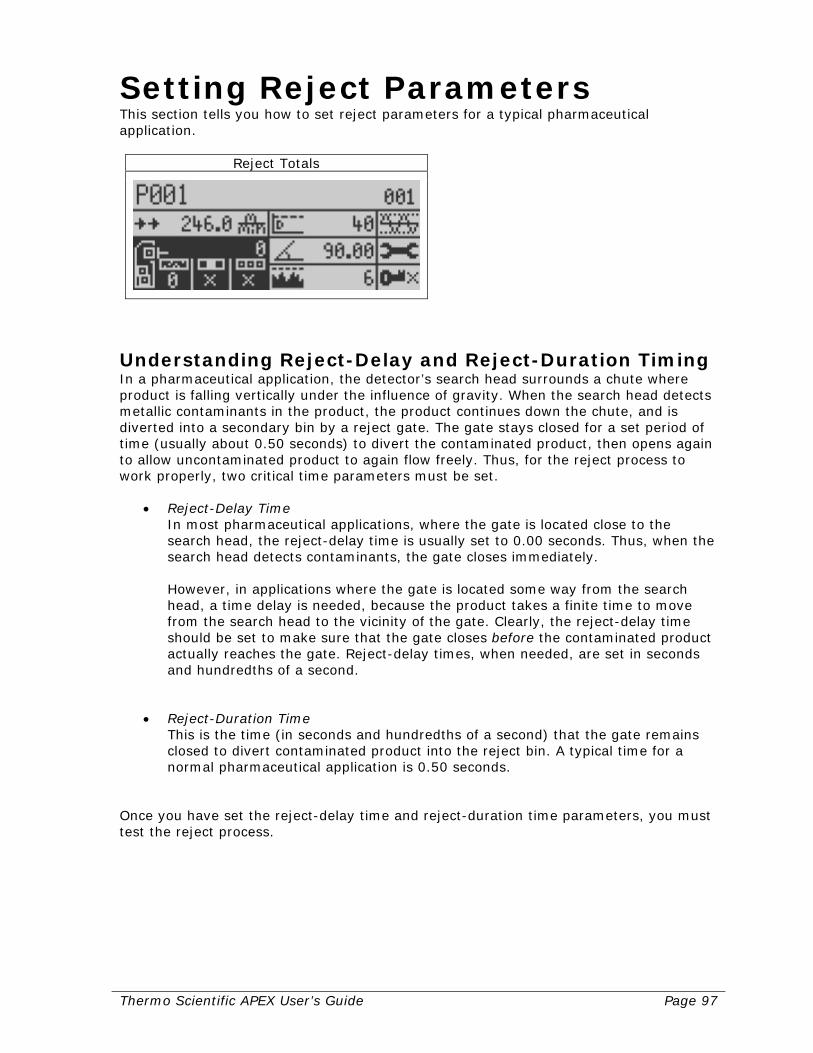
Thermo Scientific APEX User’s Guide Page 97
Setting Reject Parameters This section tells you how to set reject parameters for a typical pharmaceutical application.
Reject Totals
Understanding Reject-Delay and Reject-Duration Timing In a pharmaceutical application, the detector’s search head surrounds a chute where product is falling vertically under the influence of gravity. When the search head detects metallic contaminants in the product, the product continues down the chute, and is diverted into a secondary bin by a reject gate. The gate stays closed for a set period of time (usually about 0.50 seconds) to divert the contaminated product, then opens again to allow uncontaminated product to again flow freely. Thus, for the reject process to work properly, two critical time parameters must be set.
• Reject-Delay Time In most pharmaceutical applications, where the gate is located close to the search head, the reject-delay time is usually set to 0.00 seconds. Thus, when the search head detects contaminants, the gate closes immediately. However, in applications where the gate is located some way from the search head, a time delay is needed, because the product takes a finite time to move from the search head to the vicinity of the gate. Clearly, the reject-delay time should be set to make sure that the gate closes before the contaminated product actually reaches the gate. Reject-delay times, when needed, are set in seconds and hundredths of a second.
• Reject-Duration Time
This is the time (in seconds and hundredths of a second) that the gate remains closed to divert contaminated product into the reject bin. A typical time for a normal pharmaceutical application is 0.50 seconds.
Once you have set the reject-delay time and reject-duration time parameters, you must test the reject process.

Page 98 Thermo Scientific APEX User’s Guide
Setting the Reject-Delay Time To set the reject-delay time, do the following. 1) From the Main Menu navigate to the rejects menu.
Reject Totals
2) Press the Go button and page 1 of the rejects menu appears.
Reject 1 Distance and Duration
3) Navigate to the reject-1 distance/delay menu shown below.
Reject 1 Distance/Delay
4) Press the Go button and the reject-1 distance/delay input screen appears. Key in an
appropriate value for reject-1 distance/delay. For a typical pharmaceutical application, key in a value of 0.00 seconds. This allows the reject gate to close immediately, when metallic contaminants are detected.
Reject 1 Distance/Delay

Thermo Scientific APEX User’s Guide Page 99
5) Press the Go button to save your setting. 6) Press the Back button repeatedly to return to the Main Menu.
Setting the Reject-Duration Time To set the reject-duration time, do the following. 1) From the Main Menu navigate to the rejects menu.
Reject Totals
2) Press the Go button and page 1 of the rejects menu appears.
Reject 1…
3) Navigate to the reject-1 duration menu shown below.
Reject 1 Duration
(continued…)

Page 100 Thermo Scientific APEX User’s Guide
4) Press the Go button and the reject-1 duration input screen appears.
Reject 1 Duration
5) Key in a value for the reject-1 duration parameter. For a typical pharmaceutical
application, key in a value of 0.50. 6) Press the Go button to save your setting. 7) Press the Back button repeatedly to return to the Main Menu.
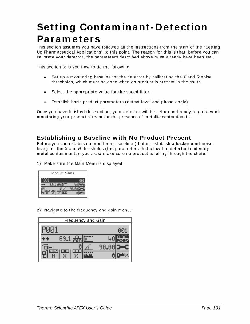
Thermo Scientific APEX User’s Guide Page 101
Setting Contaminant-Detection Parameters This section assumes you have followed all the instructions from the start of the “Setting Up Pharmaceutical Applications” to this point. The reason for this is that, before you can calibrate your detector, the parameters described above must already have been set. This section tells you how to do the following.
• Set up a monitoring baseline for the detector by calibrating the X and R noise thresholds, which must be done when no product is present in the chute.
• Select the appropriate value for the speed filter. • Establish basic product parameters (detect level and phase-angle).
Once you have finished this section, your detector will be set up and ready to go to work monitoring your product stream for the presence of metallic contaminants.
Establishing a Baseline with No Product Present Before you can establish a monitoring baseline (that is, establish a background-noise level) for the X and R thresholds (the parameters that allow the detector to identify metal contaminants), you must make sure no product is falling through the chute. 1) Make sure the Main Menu is displayed.
Product Name
2) Navigate to the frequency and gain menu.
Frequency and Gain
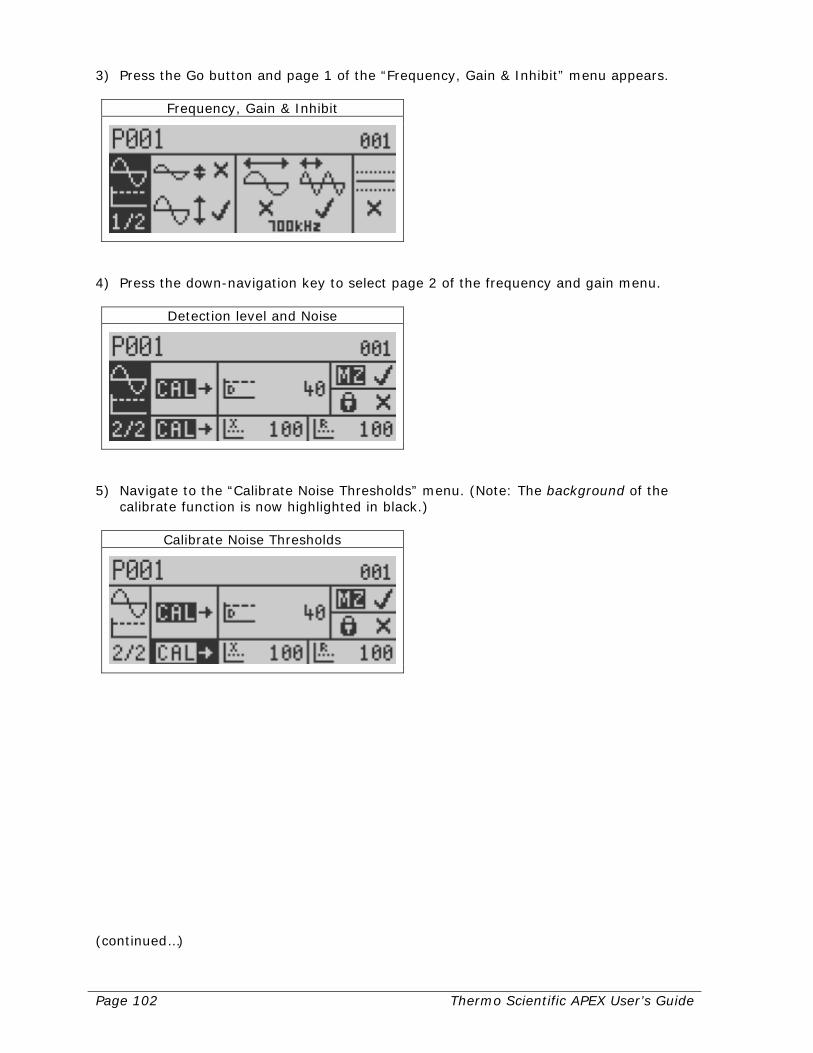
Page 102 Thermo Scientific APEX User’s Guide
3) Press the Go button and page 1 of the “Frequency, Gain & Inhibit” menu appears.
Frequency, Gain & Inhibit
4) Press the down-navigation key to select page 2 of the frequency and gain menu.
Detection level and Noise
5) Navigate to the “Calibrate Noise Thresholds” menu. (Note: The background of the
calibrate function is now highlighted in black.)
Calibrate Noise Thresholds
(continued…)

Thermo Scientific APEX User’s Guide Page 103
6) Press the Go button. The detector immediately starts measuring (calibrating) the background X and R noise thresholds, and the monitor screen (below) presents a bar graph of the progress of the calibration process. The calibration takes roughly 20 seconds to complete.
Calibrate Noise Thresholds
When finished, the monitor screen disappears and the “Calibrate Noise Threshold” menu (shown in step 5) reappears. The screen now displays the calibrated (measured) values for the X and R noise thresholds and, because these are background values, the numbers should be low. If the numbers are high, it may be difficult to detect small metal contaminants over the background noise.
• Reducing High X Noise Thresholds An X-threshold in excess of 1,000 usually indicates there is a problem with excessive vibration in your application. As a general rule, as the severity of the vibration increases, the X-threshold also increases. Possible remedies include making sure the detector is completely isolated mechanically from the surrounding chute, and/or installing shock mounts for the detector.
• Reducing High R Noise Thresholds
An R-threshold in excess of 200 usually indicates that one (or more) of the following conditions is present.
o Excessive noise from electro-magnetic currents (EMCs) and variable frequency drives (VFDs). Rectify by installing an isolation transformer and/or line reactors.
o Metal in the detector’s metal-free zone. Rectify by removing the metal. 7) If you want to manually key in a different value for either the X or R noise threshold,
make sure the “Calibrate Noise Thresholds” menu (shown in step 5) is displayed. Navigate to the appropriate menu (X or R) and press the Go button. An input screen appears, allowing you to manually enter a value.
X Threshold

Page 104 Thermo Scientific APEX User’s Guide
Choosing the Correct Speed-Filter Settings for the Rx For the Rx, the default speed-filter setting is the wide-band speed filter #2 (medium), which works well for most Rx applications where products flow at a medium angle of 35°.
• Speed filter #2—Medium (the default Rx setting) This is used typically for products flowing at a medium angle (35°).
Medium Product Speed
However, if you have products flowing at other standard angles (25° or 45°), you should use a different speed filter, as shown below.
• Speed filter #1—Slow This is used typically for products flowing at a shallow angle (25°)
Slow Product Speed
• Speed filter #3—Fast This is used typically for products flowing at a steep angle (45°).
Fast Product Speed

Thermo Scientific APEX User’s Guide Page 105
• Custom speed This setting is used when your product is flowing through the chute either very fast or very slowly, or because you are using a non-standard angle (that is, an angle different from the standard angles of 25°, 35°, and 45°). For help setting up a custom speed-filter setting, please contact Thermo Fisher Scientific—as described in the “Contacting Thermo Fisher Scientific” section at the end of the manual.
Establishing Basic Product Parameters Before putting your detector into service, you must have it learn how to identify your uncontaminated product. This is done using the detector’s full-product calibration function, which sets the following basic parameters for your product.
• Phase-angle setting
• Detect level Doing a Full-Product Calibration To do a full-product calibration, follow the instructions below. 1) Make sure product is falling through the chute. 2) Highlight your product name in the Main Menu.
Product Name
3) Press the Go button and page 1 of the product menu appears.
Product Calibrate and Name

Page 106 Thermo Scientific APEX User’s Guide
4) Press the right-navigation button to highlight the “Full Product Calibration” menu.
Full Product Calibration
The detector’s auto-calibration function (as shown by the symbols and check marks in the screen above) is now ready to do the following.
• Learn the phase angle
• Learn the detect level
• Conduct an AuditCheck, if this optional hardware is installed on your APEX.
5) Press the Go button and the “Performing Full Learn” monitor screen appears.
Performing Full Learn
(continued…)
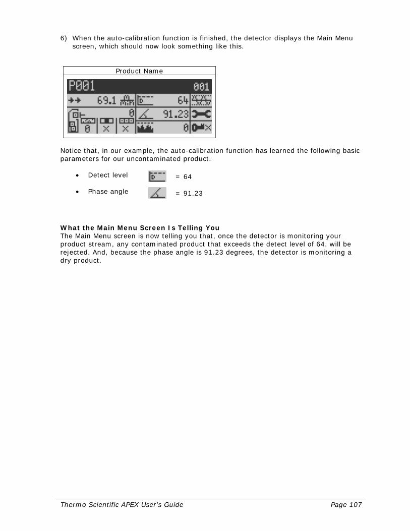
Thermo Scientific APEX User’s Guide Page 107
6) When the auto-calibration function is finished, the detector displays the Main Menu screen, which should now look something like this.
Product Name
Notice that, in our example, the auto-calibration function has learned the following basic parameters for our uncontaminated product.
• Detect level = 64
• Phase angle = 91.23
What the Main Menu Screen Is Telling You The Main Menu screen is now telling you that, once the detector is monitoring your product stream, any contaminated product that exceeds the detect level of 64, will be rejected. And, because the phase angle is 91.23 degrees, the detector is monitoring a dry product.
Page 108 Thermo Scientific APEX User’s Guide
Set-Up Check List for Pharmaceutical Applications This section lists the parameters you have already set (by following the instructions from the start of the “Setting Up Pharmaceutical Applications” section up to this point in the manual). This section also lists additional parameters you may want to set up to get your particular pharmaceutical application running to your satisfaction.
Parameters You Have Already Set Up Listed below are the parameters you have already set up for a typical pharmaceutical application. Product Parameters
• Product name Reject Parameters
• Reject-delay time • Reject-duration time
Contaminant-Detection Parameters (Set by the Detector’s Calibrate Functions)
• X and R noise thresholds • Speed-filter setting • Detect level • Phase-angle setting
Thermo Scientific APEX User’s Guide Page 109
Additional Parameters You May Want to Set Up Listed below are additional parameters you may want to set up to get your particular pharmaceutical application running to your satisfaction. Reject-Confirm Function If your gate is equipped with a position detector, this function allows the detector to confirm that, during a reject cycle, the gate has properly completed both the “open” and “close” phases of the reject cycle. In addition, if a gate failure occurs, the detector can stop the flow of product, or notify you that a gate failure has occurred—for example, because the air supply to the gate has failed, or product has built up on the gate or surrounding duct-work. For more details, see page 137. Warnings, Alarms, and Faults (WAFs) Many of the detector’s functions provide a warning, alarm, or fault when a condition needing your attention occurs. This menu—in conjunction with the appropriate hardwired external device—allows this to happen. For more details, see page 214. Copying and Pasting Product Parameters This function is particularly useful when you are testing multiple products. You can save considerable amounts of time and effort using the copy and paste functions, because you do not need to re-enter the product parameters for each product, re-run the calibrations, and so on. For more details, see page 173.

Page 110 Thermo Scientific APEX User’s Guide
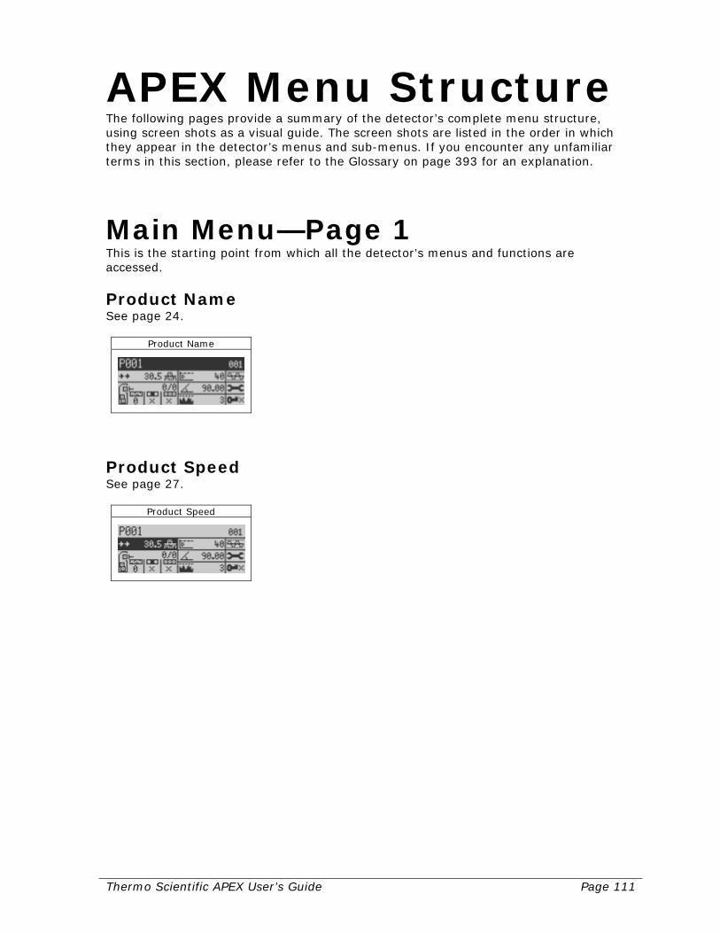
Thermo Scientific APEX User’s Guide Page 111
APEX Menu Structure The following pages provide a summary of the detector’s complete menu structure, using screen shots as a visual guide. The screen shots are listed in the order in which they appear in the detector’s menus and sub-menus. If you encounter any unfamiliar terms in this section, please refer to the Glossary on page 393 for an explanation.
Main Menu—Page 1 This is the starting point from which all the detector’s menus and functions are accessed.
Product Name See page 24.
Product Name
Product Speed See page 27.
Product Speed
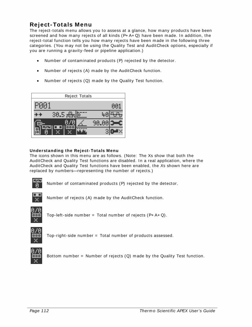
Page 112 Thermo Scientific APEX User’s Guide
Reject-Totals Menu The reject-totals menu allows you to assess at a glance, how many products have been screened and how many rejects of all kinds (P+A+Q) have been made. In addition, the reject-total function tells you how many rejects have been made in the following three categories. (You may not be using the Quality Test and AuditCheck options, especially if you are running a gravity-feed or pipeline application.)
• Number of contaminated products (P) rejected by the detector. • Number of rejects (A) made by the AuditCheck function. • Number of rejects (Q) made by the Quality Test function.
Reject Totals
Understanding the Reject-Totals Menu The icons shown in this menu are as follows. (Note: The Xs show that both the AuditCheck and Quality Test functions are disabled. In a real application, where the AuditCheck and Quality Test functions have been enabled, the Xs shown here are replaced by numbers—representing the number of rejects.)
Number of contaminated products (P) rejected by the detector.
Number of rejects (A) made by the AuditCheck function.
Top-left-side number = Total number of rejects (P+A+Q).
Top-right-side number = Total number of products assessed.
Bottom number = Number of rejects (Q) made by the Quality Test function.
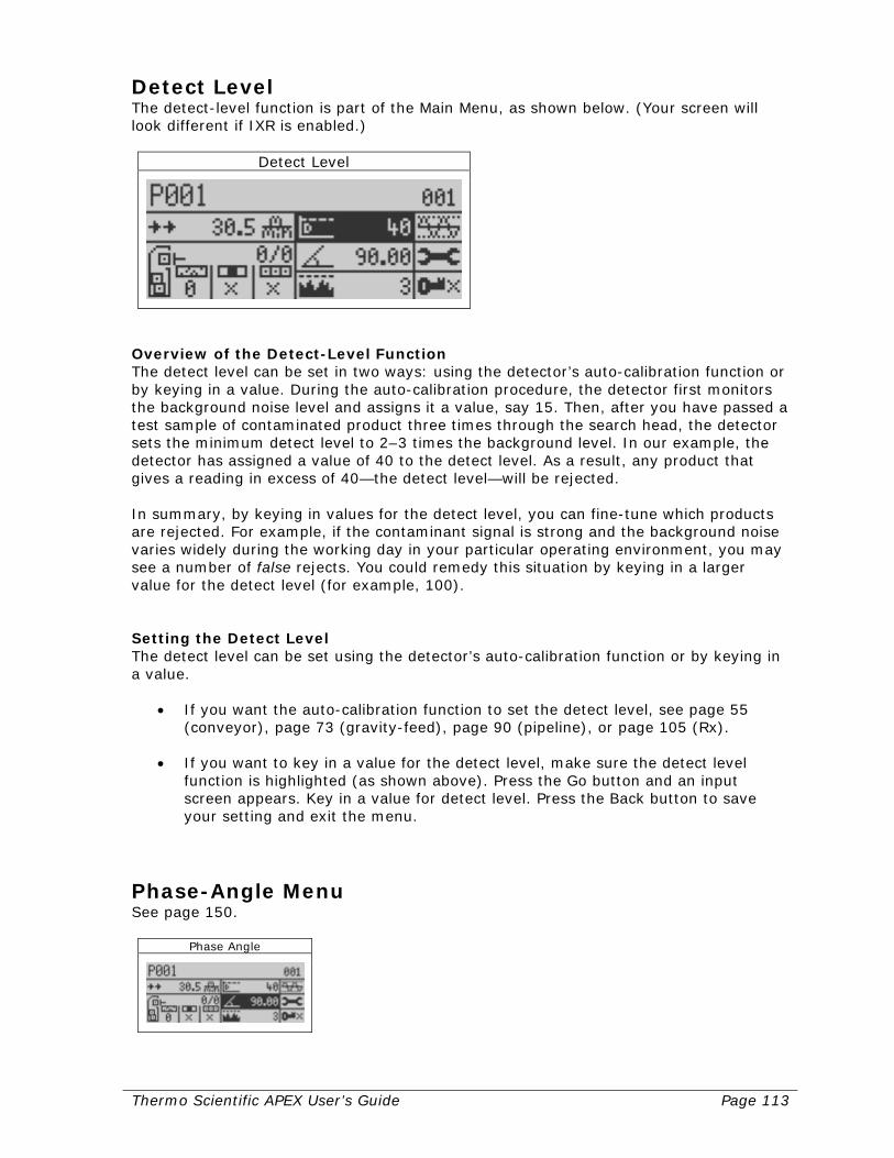
Thermo Scientific APEX User’s Guide Page 113
Detect Level The detect-level function is part of the Main Menu, as shown below. (Your screen will look different if IXR is enabled.)
Detect Level
Overview of the Detect-Level Function The detect level can be set in two ways: using the detector’s auto-calibration function or by keying in a value. During the auto-calibration procedure, the detector first monitors the background noise level and assigns it a value, say 15. Then, after you have passed a test sample of contaminated product three times through the search head, the detector sets the minimum detect level to 2–3 times the background level. In our example, the detector has assigned a value of 40 to the detect level. As a result, any product that gives a reading in excess of 40—the detect level—will be rejected. In summary, by keying in values for the detect level, you can fine-tune which products are rejected. For example, if the contaminant signal is strong and the background noise varies widely during the working day in your particular operating environment, you may see a number of false rejects. You could remedy this situation by keying in a larger value for the detect level (for example, 100). Setting the Detect Level The detect level can be set using the detector’s auto-calibration function or by keying in a value.
• If you want the auto-calibration function to set the detect level, see page 55 (conveyor), page 73 (gravity-feed), page 90 (pipeline), or page 105 (Rx).
• If you want to key in a value for the detect level, make sure the detect level
function is highlighted (as shown above). Press the Go button and an input screen appears. Key in a value for detect level. Press the Back button to save your setting and exit the menu.
Phase-Angle Menu See page 150.
Phase Angle

Page 114 Thermo Scientific APEX User’s Guide
Peak Signal The peak-signal function is a display function, meaning there are no parameters you can set for it. In other words, the peak-signal function acts purely as a gauge, and displays the highest signal seen by the search head since this function was last reset. In our example, the peak signal reading is 3, and is the highest signal produced by a series of contaminated products that passed through the search head since it was last reset.
Peak Signal
The peak-signal value can be reset in the following ways.
• If photo registration is enabled, the peak-signal value will automatically reset before each pack enters the search head or when each pack crosses the photo-eye.
• Pressing the Go button, while the peak-signal icon is highlighted, will reset the peak-signal value.
Uses of the Peak-Signal Function The peak-signal function can be used to do the following.
• Establish the level of background noise over an entire day, week, or other extended time period.
• Monitor the maximum signal produced by contaminants during a specified time
period—for example, the morning shift, a 24-hour day, a week, and so on. • Monitor the long-term trends in the detector’s signal-to-noise ratio.
Frequency and Gain Menu See page 160.
Frequency and Gain

Thermo Scientific APEX User’s Guide Page 115
System and Tools Menu See page 168.
System and Tools
Security Menu See page 249.
Security Level
Main Sub-Menu—Page 1 Page 1 of the Main Menu allows you to do a full product calibration and give the product you are testing a name. 1) Start at the Main Menu.
Product Name
2) Press the Go button and navigate to page 1 of the detector’s main sub-menu.
Product Calibrate and Name

Page 116 Thermo Scientific APEX User’s Guide
Starting a Complete Product Calibration For more information about doing a full product calibration, see the relevant section for your particular application.
• Conveyor applications—see page 55. • Gravity-feed applications—see page 73. • Pipeline applications—see page 90. • Pharmaceutical applications—see page 105.
Full Product Calibration
Editing the Product Name See page 24.
Edit Product Name
Main Sub-Menu—Page 2 1) Start at the Main Menu.
Product Name
2) Press the Go button. 3) Navigate to page 2 of the detector’s main sub-menu.
Product Shape and Flow

Thermo Scientific APEX User’s Guide Page 117
Setting the Pack Length See page 35. (This is used only in conveyor applications with a product photo eye, and in pharmaceutical applications.)
Pack Length
Setting the Pack Gap See page 40. (This is used only in conveyor applications with a product photo eye, and in pharmaceutical applications.)
Pack Gap
Setting the No-Pack Distance See page 37. (This is used only in conveyor applications with a product photo eye, and in pharmaceutical applications.)
Detection no-Pack distance
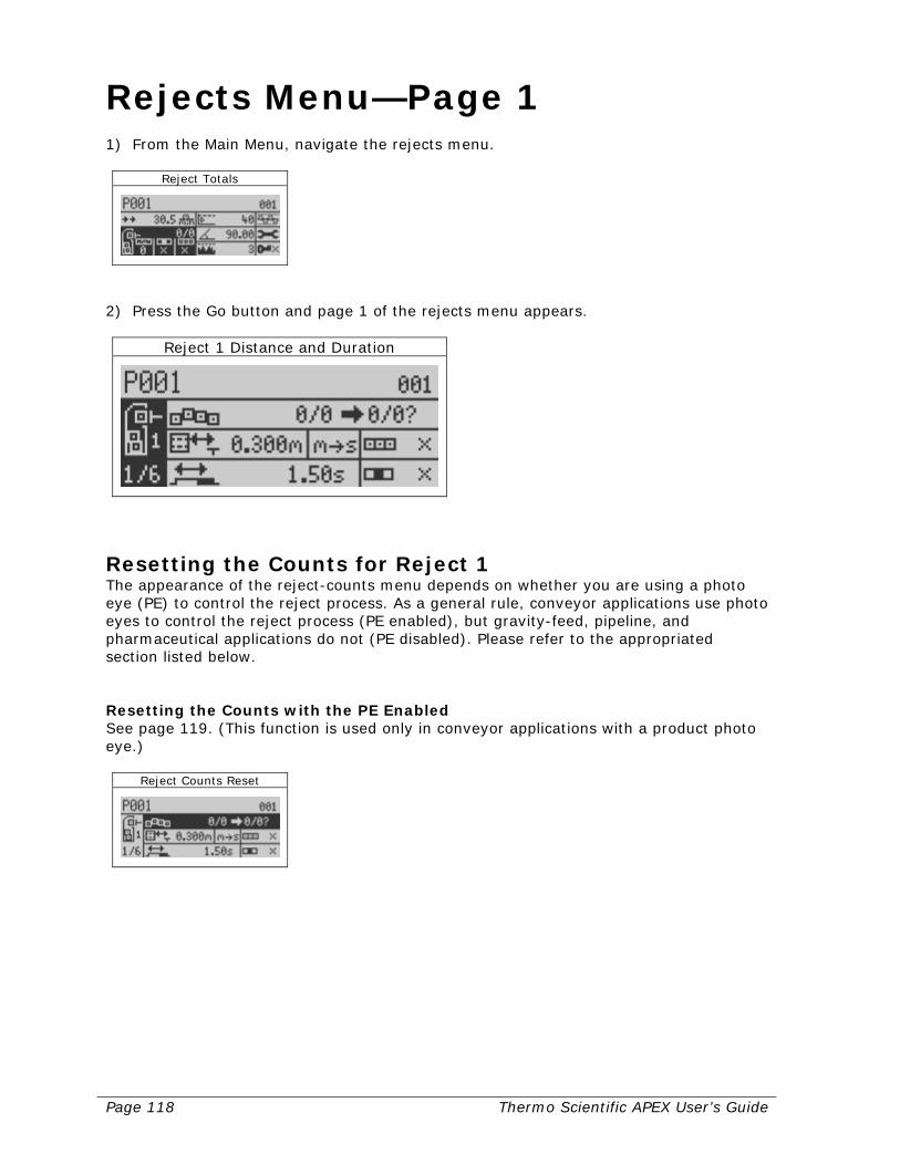
Page 118 Thermo Scientific APEX User’s Guide
Rejects Menu—Page 1 1) From the Main Menu, navigate the rejects menu.
Reject Totals
2) Press the Go button and page 1 of the rejects menu appears.
Reject 1 Distance and Duration
Resetting the Counts for Reject 1 The appearance of the reject-counts menu depends on whether you are using a photo eye (PE) to control the reject process. As a general rule, conveyor applications use photo eyes to control the reject process (PE enabled), but gravity-feed, pipeline, and pharmaceutical applications do not (PE disabled). Please refer to the appropriated section listed below. Resetting the Counts with the PE Enabled See page 119. (This function is used only in conveyor applications with a product photo eye.)
Reject Counts Reset
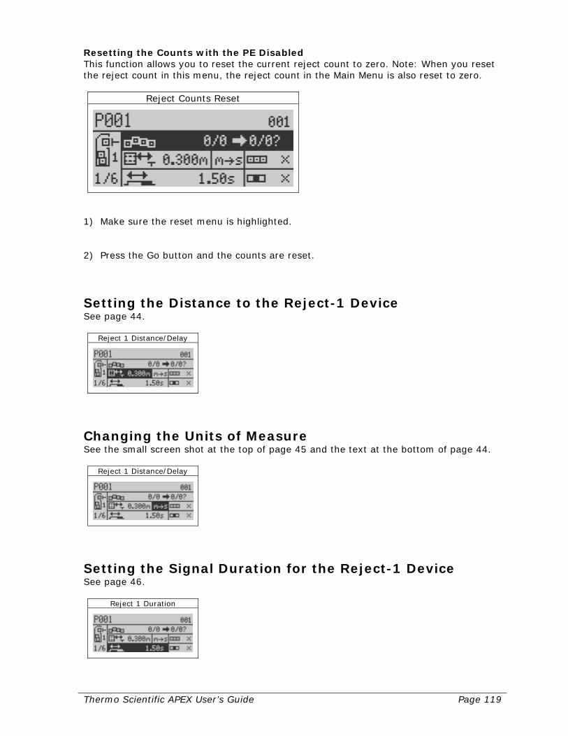
Thermo Scientific APEX User’s Guide Page 119
Resetting the Counts with the PE Disabled This function allows you to reset the current reject count to zero. Note: When you reset the reject count in this menu, the reject count in the Main Menu is also reset to zero.
Reject Counts Reset
1) Make sure the reset menu is highlighted. 2) Press the Go button and the counts are reset.
Setting the Distance to the Reject-1 Device See page 44.
Reject 1 Distance/Delay
Changing the Units of Measure See the small screen shot at the top of page 45 and the text at the bottom of page 44.
Reject 1 Distance/Delay
Setting the Signal Duration for the Reject-1 Device See page 46.
Reject 1 Duration
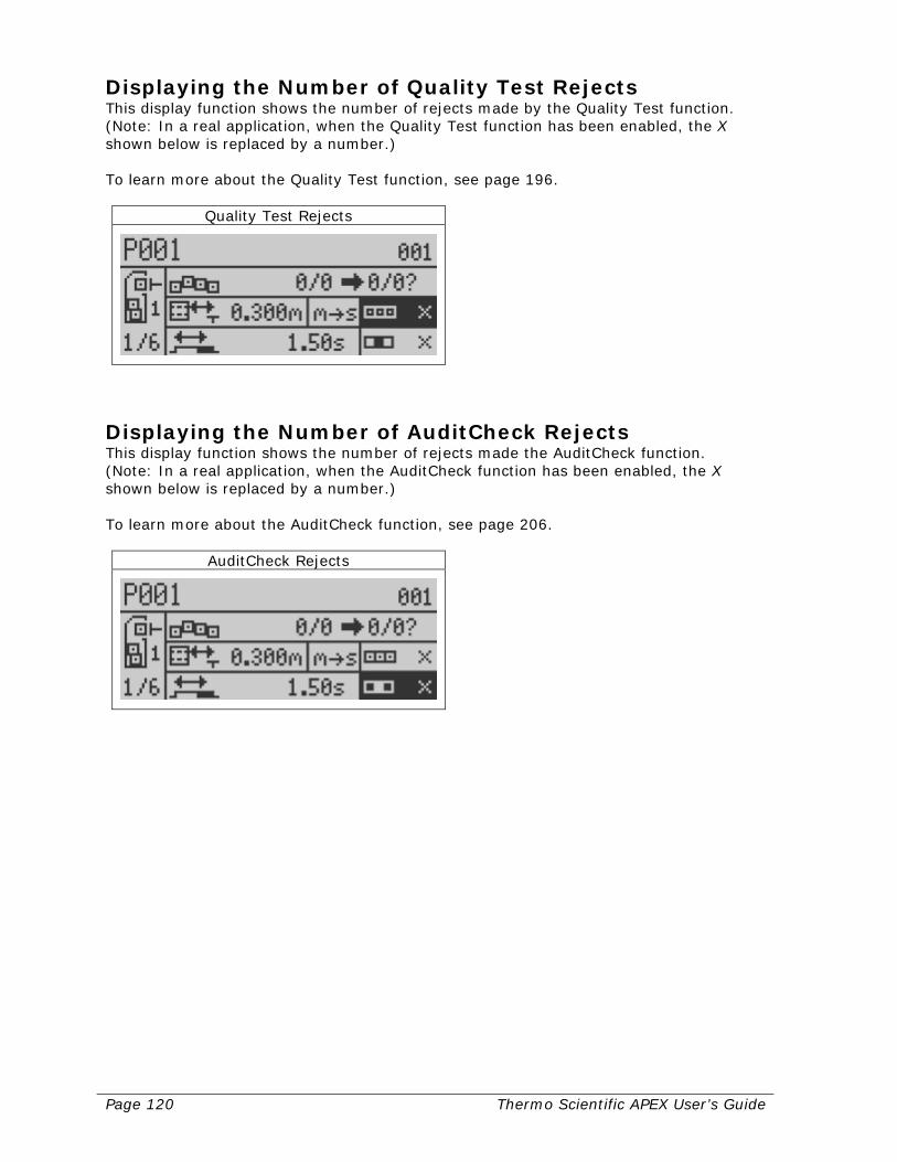
Page 120 Thermo Scientific APEX User’s Guide
Displaying the Number of Quality Test Rejects This display function shows the number of rejects made by the Quality Test function. (Note: In a real application, when the Quality Test function has been enabled, the X shown below is replaced by a number.) To learn more about the Quality Test function, see page 196.
Quality Test Rejects
Displaying the Number of AuditCheck Rejects This display function shows the number of rejects made the AuditCheck function. (Note: In a real application, when the AuditCheck function has been enabled, the X shown below is replaced by a number.) To learn more about the AuditCheck function, see page 206.
AuditCheck Rejects
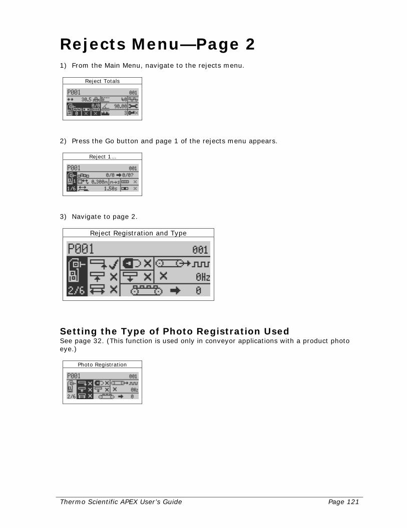
Thermo Scientific APEX User’s Guide Page 121
Rejects Menu—Page 2 1) From the Main Menu, navigate to the rejects menu.
Reject Totals
2) Press the Go button and page 1 of the rejects menu appears.
Reject 1…
3) Navigate to page 2.
Reject Registration and Type
Setting the Type of Photo Registration Used See page 32. (This function is used only in conveyor applications with a product photo eye.)
Photo Registration

Page 122 Thermo Scientific APEX User’s Guide
Setting the Latching-Reject Function (Reject 1) This function can only be used to latch your reject-1 device. The default setting for the latching-reject function is “off,” as shown by the X next to the padlock icon in the screen below.
Latching Reject
Example of Using the Latching-Reject Function The latching-reject function is normally used only in conveyor applications, where shop-floor personnel are responsible for manually removing contaminated product from the conveyor. When contaminants are detected, the detector sends a signal, which remains on (“latched”) until manually reset. The output signal to the conveyor or buzzer remains latched on, until manually reset by the operator. Enabling the Latching-Reject Function To enable the latching-reject function, do the following. 1) Make sure the latching-reject function is highlighted, as shown above. 2) Press the Go button and a check mark appears. The latching-reject function is now
active.
Latching Reject
3) Press the Back button to exit the function.
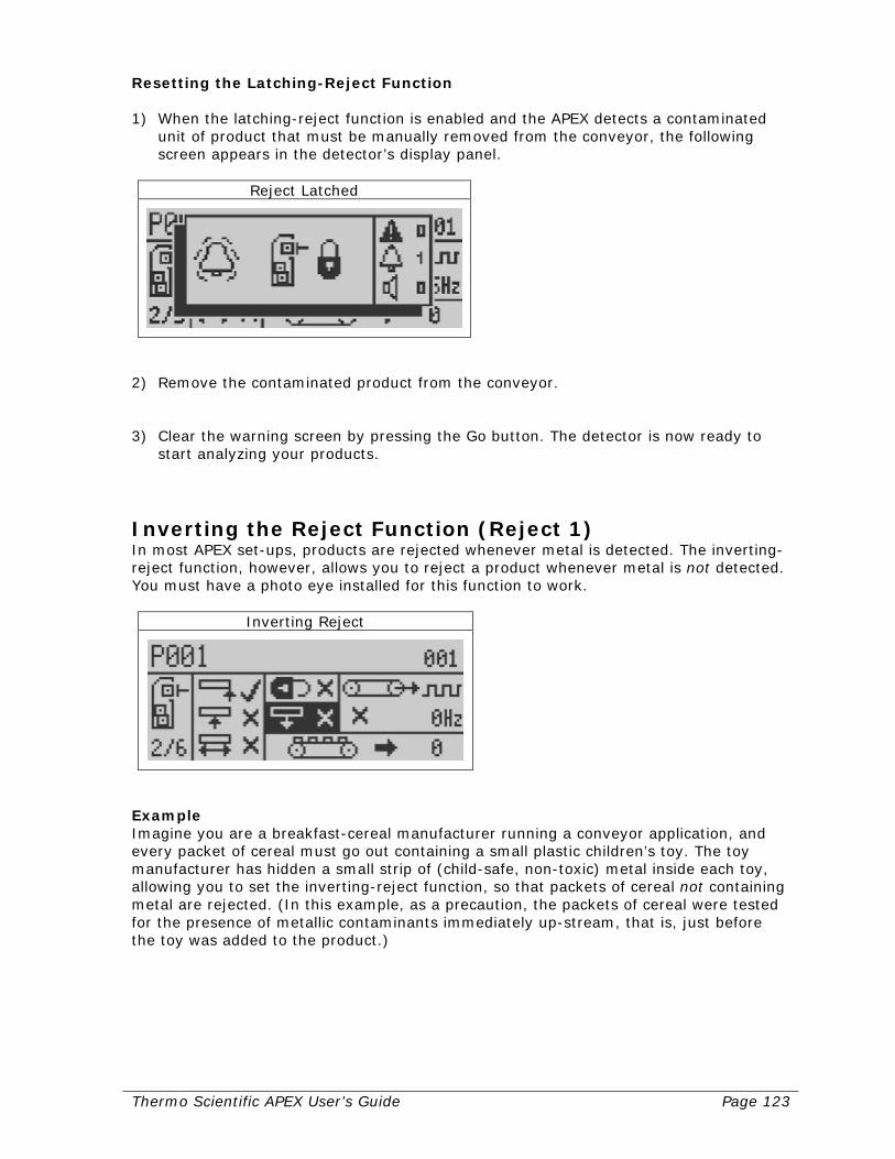
Thermo Scientific APEX User’s Guide Page 123
Resetting the Latching-Reject Function 1) When the latching-reject function is enabled and the APEX detects a contaminated
unit of product that must be manually removed from the conveyor, the following screen appears in the detector’s display panel.
Reject Latched
2) Remove the contaminated product from the conveyor. 3) Clear the warning screen by pressing the Go button. The detector is now ready to
start analyzing your products.
Inverting the Reject Function (Reject 1) In most APEX set-ups, products are rejected whenever metal is detected. The inverting-reject function, however, allows you to reject a product whenever metal is not detected. You must have a photo eye installed for this function to work.
Inverting Reject
Example Imagine you are a breakfast-cereal manufacturer running a conveyor application, and every packet of cereal must go out containing a small plastic children’s toy. The toy manufacturer has hidden a small strip of (child-safe, non-toxic) metal inside each toy, allowing you to set the inverting-reject function, so that packets of cereal not containing metal are rejected. (In this example, as a precaution, the packets of cereal were tested for the presence of metallic contaminants immediately up-stream, that is, just before the toy was added to the product.)

Page 124 Thermo Scientific APEX User’s Guide
Setting the Inverting-Reject Function To enable the inverting-reject function, do the following. 1) Make sure the inverting-reject function is highlighted, as shown above. 2) Press the Go button and a check mark appears. The inverting-reject function is now
active.
Inverting Reject
3) Press the Back button to exit the function.
Calibrating the Speed-Encoder Function This function is used only in conveyor applications. A speed encoder must be attached to your conveyor and hardwired to the detector. In addition, the detector’s speed-encoder function must be calibrated.
Speed Encoder
Advantages of Using the Speed-Encoder Function There are many advantages of enabling the speed-encoder function. First, whenever you change conveyor speed, the detector automatically displays the correct, updated product speed in the main menu. Second, any other detector parameters that rely on product speed—such as reject delay, reject duration, and speed filtering—are automatically recalibrated to account for the change in product speed. This is particularly useful if you monitor multiple products at different product speeds, or inspect other products by manually passing them through the search head. Thus, you can monitor Product 1 with the speed-encoder parameter enabled, and Product 2 with the parameter disabled. The speed-encoder function is a product-specific parameter.

Thermo Scientific APEX User’s Guide Page 125
Overview of Set Up Some conveyor systems, especially those that can be set to run at variable speeds, have a built-in speed encoder. A typical speed encoder is constructed using a disk-shaped gear with teeth around the periphery, and is attached to a roller on the conveyor. The teeth of the gear pass in front of a photo eye, giving a square signal (as shown in the figure below) whose frequency is proportional to the speed of the conveyor. In a typical conveyor set up, the signal from the speed encoder is hard wired to Input 1 on the detector’s wiring board. Input 1 on the APEX is the dedicated physical input for the speed-encoder signal. For wiring details, see page 289. In order for the speed-encoder function to work optimally, the speed-encoder gear should be large and have a large number of teeth, so that the maximum conveyor speed produces a signal of at least 500 Hz but no greater than 2,000 Hz. In addition, any signal from the speed encoder should not fluctuate or have missing pulses. A nice steady signal is required. A fluctuating signal will cause large changes in the speed display and will adversely affect all speed-related parameters. Acceptable Values for Inputs from the Speed-Encoder The following table shows the resolution at the calibrated frequency.
Frequency (Hz) Resolution (f/m)
50 / 55 98.4–108.3 100 / 105 98.4–103.3 200 / 205 99.7–102.2 500 / 505 99.9–100.9 750 / 755 99.9–100.6 1000 / 1005 99.9–100.4 1500 / 1505 99.8–100.2 2000 / 2005 99.8–100.1
f/m = feet per minute
Calibrating the Speed-Encoder Function You must calibrate the speed-encoder function before you can use it. 1) Turn on the conveyor and set the belt speed to maximum. Use a tachometer to
record the speed. 2) Go to the product-speed function in the Main Menu, as described on page 27, and
key in the reading for maximum belt speed. (We keyed in 100 feet per minute.)
Product Speed
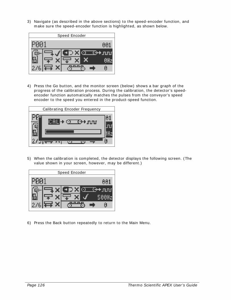
Page 126 Thermo Scientific APEX User’s Guide
3) Navigate (as described in the above sections) to the speed-encoder function, and make sure the speed-encoder function is highlighted, as shown below.
Speed Encoder
4) Press the Go button, and the monitor screen (below) shows a bar graph of the
progress of the calibration process. During the calibration, the detector’s speed-encoder function automatically matches the pulses from the conveyor’s speed encoder to the speed you entered in the product-speed function.
Calibrating Encoder Frequency
5) When the calibration is completed, the detector displays the following screen. (The
value shown in your screen, however, may be different.)
Speed Encoder
6) Press the Back button repeatedly to return to the Main Menu.
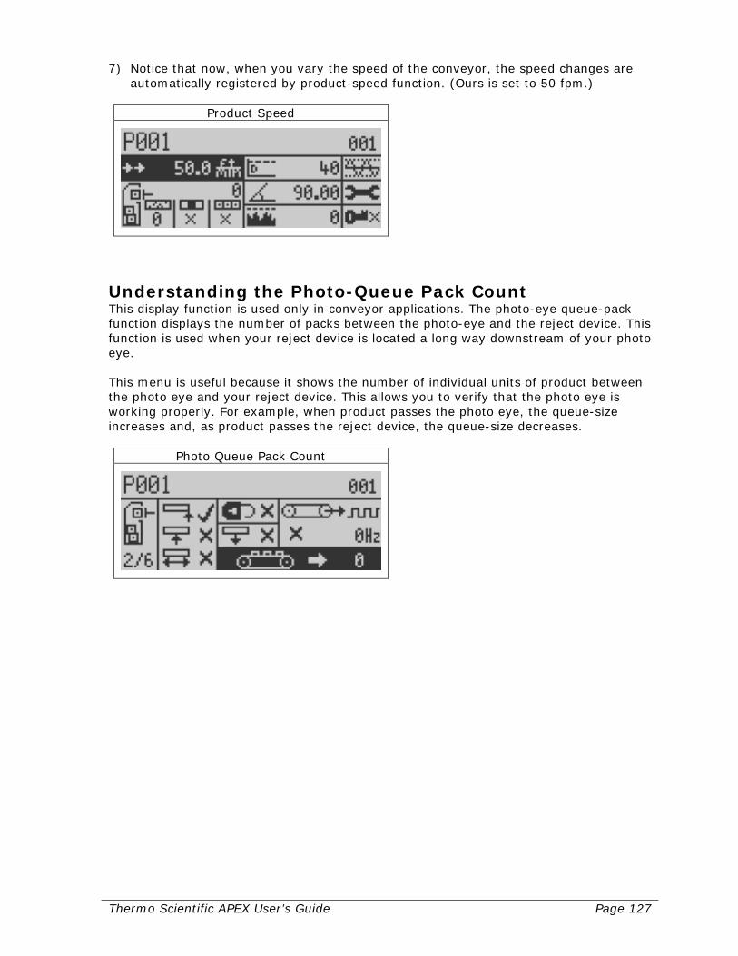
Thermo Scientific APEX User’s Guide Page 127
7) Notice that now, when you vary the speed of the conveyor, the speed changes are automatically registered by product-speed function. (Ours is set to 50 fpm.)
Product Speed
Understanding the Photo-Queue Pack Count This display function is used only in conveyor applications. The photo-eye queue-pack function displays the number of packs between the photo-eye and the reject device. This function is used when your reject device is located a long way downstream of your photo eye. This menu is useful because it shows the number of individual units of product between the photo eye and your reject device. This allows you to verify that the photo eye is working properly. For example, when product passes the photo eye, the queue-size increases and, as product passes the reject device, the queue-size decreases.
Photo Queue Pack Count
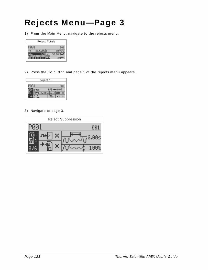
Page 128 Thermo Scientific APEX User’s Guide
Rejects Menu—Page 3 1) From the Main Menu, navigate to the rejects menu.
Reject Totals
2) Press the Go button and page 1 of the rejects menu appears.
Reject 1…
3) Navigate to page 3.
Reject Suppression

Thermo Scientific APEX User’s Guide Page 129
Suppressing Rejection Using an External Trigger (Reject 1) When the suppress-rejection function is enabled, you can manually suppress the reject device. This is useful when you are conducting a Quality Test or other manual test of the detector’s ability to detect contamination. For this function to work, you must do both of the following.
• Hardwire the button or other triggering device to one of the inputs (Input 3–6) on
the detector’s wiring board (the physical set-up), see page 289. • Tell the detector which input is being used (the logical set-up). For more
information, about assigning inputs and logical set-up procedures, see page 222. 1) Make sure the suppression external trigger menu is highlighted.
Suppression External Trigger
2) Press the Go button and a check mark appears. The suppress-rejection external
trigger function is now enabled.
Suppression External Trigger
3) Press the Back button to exit the menu.
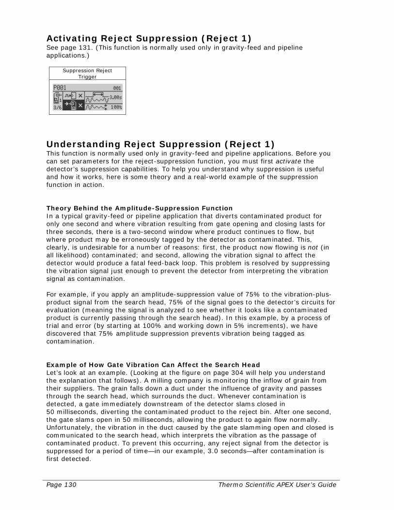
Page 130 Thermo Scientific APEX User’s Guide
Activating Reject Suppression (Reject 1) See page 131. (This function is normally used only in gravity-feed and pipeline applications.)
Suppression Reject Trigger
Understanding Reject Suppression (Reject 1) This function is normally used only in gravity-feed and pipeline applications. Before you can set parameters for the reject-suppression function, you must first activate the detector’s suppression capabilities. To help you understand why suppression is useful and how it works, here is some theory and a real-world example of the suppression function in action. Theory Behind the Amplitude-Suppression Function In a typical gravity-feed or pipeline application that diverts contaminated product for only one second and where vibration resulting from gate opening and closing lasts for three seconds, there is a two-second window where product continues to flow, but where product may be erroneously tagged by the detector as contaminated. This, clearly, is undesirable for a number of reasons: first, the product now flowing is not (in all likelihood) contaminated; and second, allowing the vibration signal to affect the detector would produce a fatal feed-back loop. This problem is resolved by suppressing the vibration signal just enough to prevent the detector from interpreting the vibration signal as contamination. For example, if you apply an amplitude-suppression value of 75% to the vibration-plus-product signal from the search head, 75% of the signal goes to the detector’s circuits for evaluation (meaning the signal is analyzed to see whether it looks like a contaminated product is currently passing through the search head). In this example, by a process of trial and error (by starting at 100% and working down in 5% increments), we have discovered that 75% amplitude suppression prevents vibration being tagged as contamination. Example of How Gate Vibration Can Affect the Search Head Let’s look at an example. (Looking at the figure on page 304 will help you understand the explanation that follows). A milling company is monitoring the inflow of grain from their suppliers. The grain falls down a duct under the influence of gravity and passes through the search head, which surrounds the duct. Whenever contamination is detected, a gate immediately downstream of the detector slams closed in 50 milliseconds, diverting the contaminated product to the reject bin. After one second, the gate slams open in 50 milliseconds, allowing the product to again flow normally. Unfortunately, the vibration in the duct caused by the gate slamming open and closed is communicated to the search head, which interprets the vibration as the passage of contaminated product. To prevent this occurring, any reject signal from the detector is suppressed for a period of time—in our example, 3.0 seconds—after contamination is first detected.
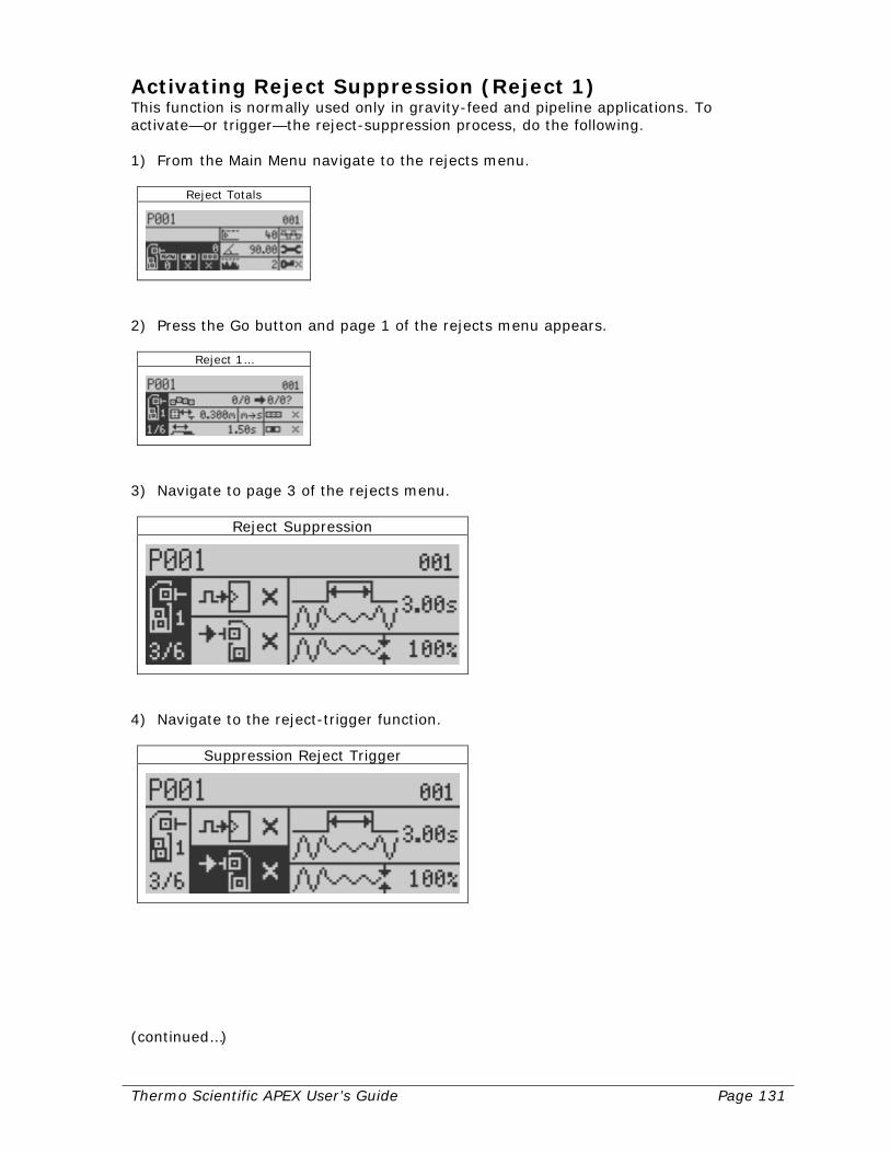
Thermo Scientific APEX User’s Guide Page 131
Activating Reject Suppression (Reject 1) This function is normally used only in gravity-feed and pipeline applications. To activate—or trigger—the reject-suppression process, do the following. 1) From the Main Menu navigate to the rejects menu.
Reject Totals
2) Press the Go button and page 1 of the rejects menu appears.
Reject 1…
3) Navigate to page 3 of the rejects menu.
Reject Suppression
4) Navigate to the reject-trigger function.
Suppression Reject Trigger
(continued…)
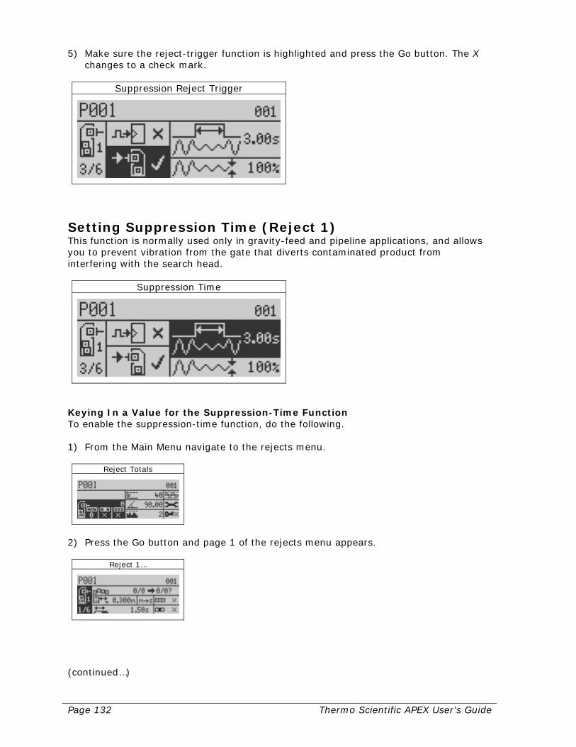
Page 132 Thermo Scientific APEX User’s Guide
5) Make sure the reject-trigger function is highlighted and press the Go button. The X changes to a check mark.
Suppression Reject Trigger
Setting Suppression Time (Reject 1) This function is normally used only in gravity-feed and pipeline applications, and allows you to prevent vibration from the gate that diverts contaminated product from interfering with the search head.
Suppression Time
Keying In a Value for the Suppression-Time Function To enable the suppression-time function, do the following. 1) From the Main Menu navigate to the rejects menu.
Reject Totals
2) Press the Go button and page 1 of the rejects menu appears.
Reject 1…
(continued…)

Thermo Scientific APEX User’s Guide Page 133
3) Press the down-navigation button twice and page 3 of the rejects menu appears.
Reject Suppression
4) Navigate to the suppression-time menu.
Suppression Time
5) Press the Go button and an input screen appears. Key in the desired suppression
time (in seconds and hundredths of a second). In our example, we accepted the current suppression time of 3.00 seconds.
Suppression Time
6) Press the Go button to save your setting and exit the menu.

Page 134 Thermo Scientific APEX User’s Guide
Setting Amplitude Suppression (Reject 1) This function is normally used only in gravity-feed and pipeline applications, and is used in conjunction with the suppression-time function described above. The amplitude-suppression function is used to tell the detector how much amplitude suppression to apply to the vibration signal affecting the search head. This is important because vibrations generate a vibration signal in the search head, and these may have the same characteristics as a contaminated product signal. As a result, the detector may interpret vibration as contamination.
Suppression Amplitude
Keying In a Value for Amplitude Suppression To key in a value for amplitude suppression, do the following. 1) Follow steps 1–3 in the section above to get to page 3 of the rejects menu.
Reject Suppression
2) Navigate to the amplitude-suppression function and make sure it is highlighted.
Suppression Amplitude
(continued…)
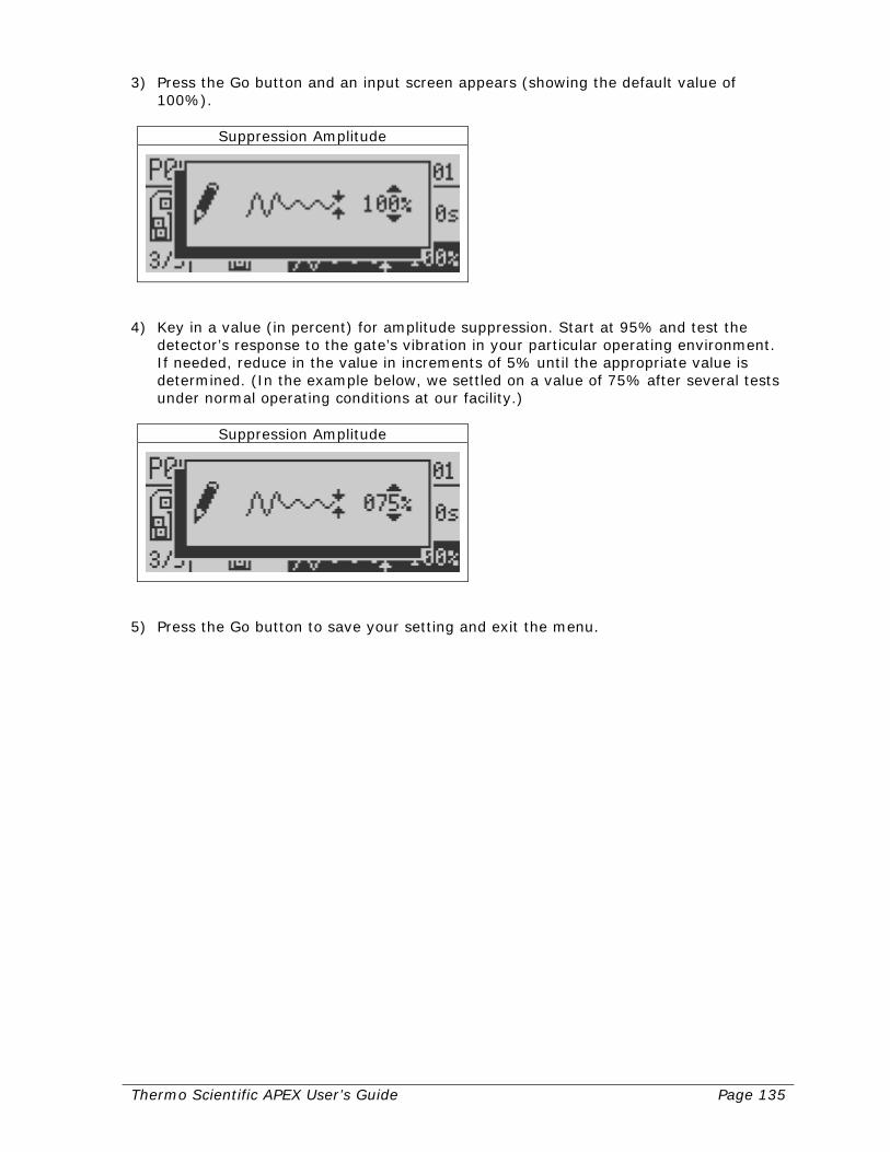
Thermo Scientific APEX User’s Guide Page 135
3) Press the Go button and an input screen appears (showing the default value of 100%).
Suppression Amplitude
4) Key in a value (in percent) for amplitude suppression. Start at 95% and test the
detector’s response to the gate’s vibration in your particular operating environment. If needed, reduce in the value in increments of 5% until the appropriate value is determined. (In the example below, we settled on a value of 75% after several tests under normal operating conditions at our facility.)
Suppression Amplitude
5) Press the Go button to save your setting and exit the menu.
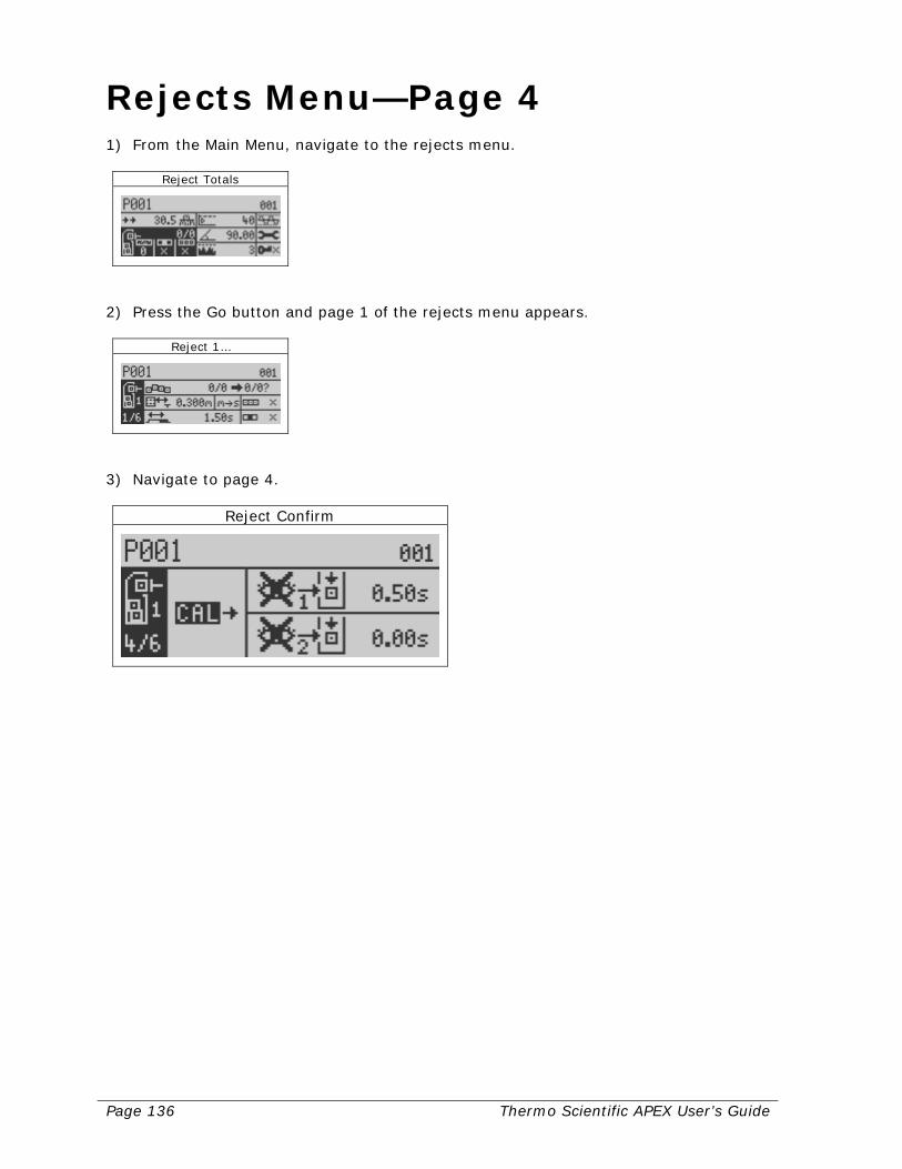
Page 136 Thermo Scientific APEX User’s Guide
Rejects Menu—Page 4 1) From the Main Menu, navigate to the rejects menu.
Reject Totals
2) Press the Go button and page 1 of the rejects menu appears.
Reject 1…
3) Navigate to page 4.
Reject Confirm
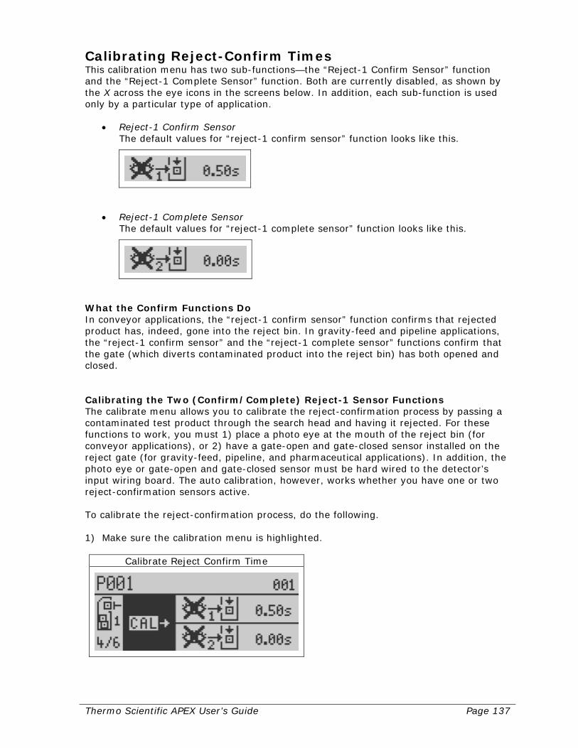
Thermo Scientific APEX User’s Guide Page 137
Calibrating Reject-Confirm Times This calibration menu has two sub-functions—the “Reject-1 Confirm Sensor” function and the “Reject-1 Complete Sensor” function. Both are currently disabled, as shown by the X across the eye icons in the screens below. In addition, each sub-function is used only by a particular type of application.
• Reject-1 Confirm Sensor The default values for “reject-1 confirm sensor” function looks like this.
• Reject-1 Complete Sensor The default values for “reject-1 complete sensor” function looks like this.
What the Confirm Functions Do In conveyor applications, the “reject-1 confirm sensor” function confirms that rejected product has, indeed, gone into the reject bin. In gravity-feed and pipeline applications, the “reject-1 confirm sensor” and the “reject-1 complete sensor” functions confirm that the gate (which diverts contaminated product into the reject bin) has both opened and closed. Calibrating the Two (Confirm/Complete) Reject-1 Sensor Functions The calibrate menu allows you to calibrate the reject-confirmation process by passing a contaminated test product through the search head and having it rejected. For these functions to work, you must 1) place a photo eye at the mouth of the reject bin (for conveyor applications), or 2) have a gate-open and gate-closed sensor installed on the reject gate (for gravity-feed, pipeline, and pharmaceutical applications). In addition, the photo eye or gate-open and gate-closed sensor must be hard wired to the detector’s input wiring board. The auto calibration, however, works whether you have one or two reject-confirmation sensors active. To calibrate the reject-confirmation process, do the following. 1) Make sure the calibration menu is highlighted.
Calibrate Reject Confirm Time
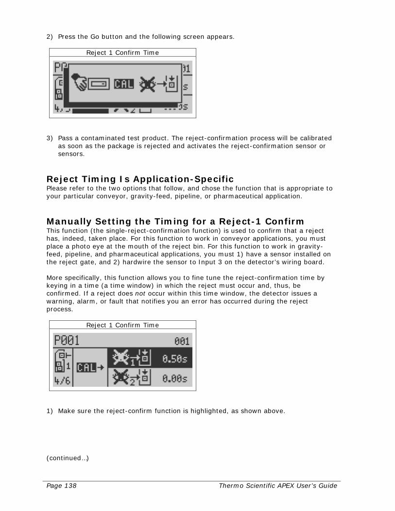
Page 138 Thermo Scientific APEX User’s Guide
2) Press the Go button and the following screen appears.
Reject 1 Confirm Time
3) Pass a contaminated test product. The reject-confirmation process will be calibrated
as soon as the package is rejected and activates the reject-confirmation sensor or sensors.
Reject Timing Is Application-Specific Please refer to the two options that follow, and chose the function that is appropriate to your particular conveyor, gravity-feed, pipeline, or pharmaceutical application.
Manually Setting the Timing for a Reject-1 Confirm This function (the single-reject-confirmation function) is used to confirm that a reject has, indeed, taken place. For this function to work in conveyor applications, you must place a photo eye at the mouth of the reject bin. For this function to work in gravity-feed, pipeline, and pharmaceutical applications, you must 1) have a sensor installed on the reject gate, and 2) hardwire the sensor to Input 3 on the detector’s wiring board. More specifically, this function allows you to fine tune the reject-confirmation time by keying in a time (a time window) in which the reject must occur and, thus, be confirmed. If a reject does not occur within this time window, the detector issues a warning, alarm, or fault that notifies you an error has occurred during the reject process.
Reject 1 Confirm Time
1) Make sure the reject-confirm function is highlighted, as shown above. (continued…)
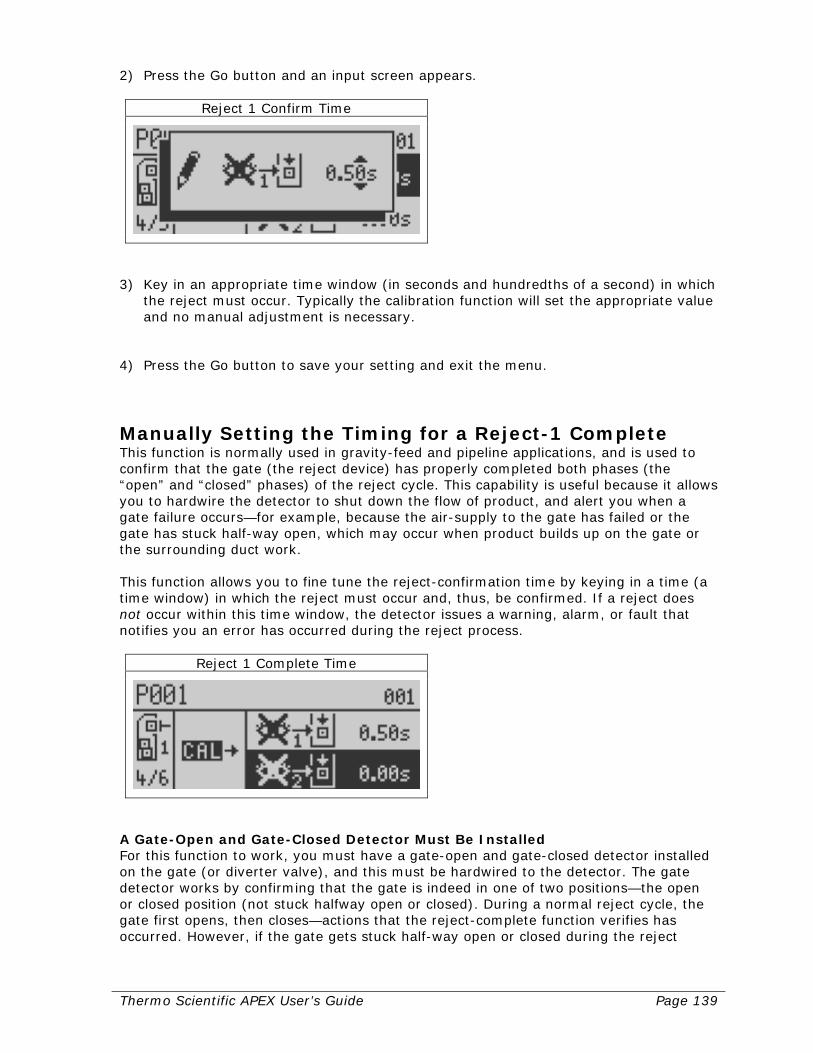
Thermo Scientific APEX User’s Guide Page 139
2) Press the Go button and an input screen appears.
Reject 1 Confirm Time
3) Key in an appropriate time window (in seconds and hundredths of a second) in which
the reject must occur. Typically the calibration function will set the appropriate value and no manual adjustment is necessary.
4) Press the Go button to save your setting and exit the menu.
Manually Setting the Timing for a Reject-1 Complete This function is normally used in gravity-feed and pipeline applications, and is used to confirm that the gate (the reject device) has properly completed both phases (the “open” and “closed” phases) of the reject cycle. This capability is useful because it allows you to hardwire the detector to shut down the flow of product, and alert you when a gate failure occurs—for example, because the air-supply to the gate has failed or the gate has stuck half-way open, which may occur when product builds up on the gate or the surrounding duct work. This function allows you to fine tune the reject-confirmation time by keying in a time (a time window) in which the reject must occur and, thus, be confirmed. If a reject does not occur within this time window, the detector issues a warning, alarm, or fault that notifies you an error has occurred during the reject process.
Reject 1 Complete Time
A Gate-Open and Gate-Closed Detector Must Be Installed For this function to work, you must have a gate-open and gate-closed detector installed on the gate (or diverter valve), and this must be hardwired to the detector. The gate detector works by confirming that the gate is indeed in one of two positions—the open or closed position (not stuck halfway open or closed). During a normal reject cycle, the gate first opens, then closes—actions that the reject-complete function verifies has occurred. However, if the gate gets stuck half-way open or closed during the reject

Page 140 Thermo Scientific APEX User’s Guide
cycle, the reject will not be confirmed, and the flow of product can be stopped and an alarm triggered notifying you of the problem. Keying In a Value for the Reject 1 Complete To enable the “reject-1 complete” function for gravity-feed, pipeline, and pharmaceutical applications, do as follows. 1) Make sure that your “reject-1 confirm” and “reject-1 complete” inputs have been
enabled and the sensors hardwired to the appropriate input on the detector’s wiring board.
2) Make sure the “reject-1 confirm” function is highlighted (as shown above). 3) Press the Go button and an input screen appears.
Reject 1 Complete Time
4) Key in an appropriate time window (in seconds and hundredths of a second) in which
the reject must occur. Typically the calibration function will set the appropriate value and no manual adjustment is necessary.
5) Press the Go button to save your setting and exit the menu.

Thermo Scientific APEX User’s Guide Page 141
Rejects Menu—Page 5 Page 5 of the rejects menu is used to set up parameters for your reject-2 device. Please note, however, that the photo-registration function cannot be used with a reject-2 device. 1) From the Main Menu, navigate to the rejects menu.
Reject Totals
2) Press the Go button and page 1 of the rejects menu appears.
Reject…
3) Navigate to page 5.
Reject 2 Distance and Duration
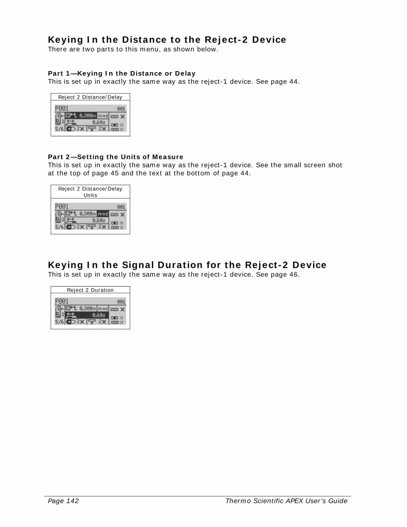
Page 142 Thermo Scientific APEX User’s Guide
Keying In the Distance to the Reject-2 Device There are two parts to this menu, as shown below. Part 1—Keying In the Distance or Delay This is set up in exactly the same way as the reject-1 device. See page 44.
Reject 2 Distance/Delay
Part 2—Setting the Units of Measure This is set up in exactly the same way as the reject-1 device. See the small screen shot at the top of page 45 and the text at the bottom of page 44.
Reject 2 Distance/Delay Units
Keying In the Signal Duration for the Reject-2 Device This is set up in exactly the same way as the reject-1 device. See page 46.
Reject 2 Duration
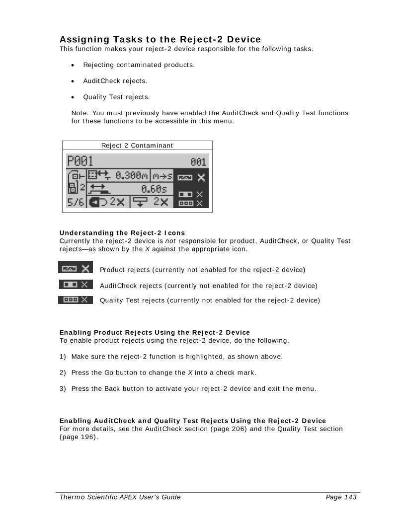
Thermo Scientific APEX User’s Guide Page 143
Assigning Tasks to the Reject-2 Device This function makes your reject-2 device responsible for the following tasks.
• Rejecting contaminated products. • AuditCheck rejects. • Quality Test rejects. Note: You must previously have enabled the AuditCheck and Quality Test functions for these functions to be accessible in this menu.
Reject 2 Contaminant
Understanding the Reject-2 Icons Currently the reject-2 device is not responsible for product, AuditCheck, or Quality Test rejects—as shown by the X against the appropriate icon.
Product rejects (currently not enabled for the reject-2 device)
AuditCheck rejects (currently not enabled for the reject-2 device)
Quality Test rejects (currently not enabled for the reject-2 device) Enabling Product Rejects Using the Reject-2 Device To enable product rejects using the reject-2 device, do the following. 1) Make sure the reject-2 function is highlighted, as shown above. 2) Press the Go button to change the X into a check mark. 3) Press the Back button to activate your reject-2 device and exit the menu. Enabling AuditCheck and Quality Test Rejects Using the Reject-2 Device For more details, see the AuditCheck section (page 206) and the Quality Test section (page 196).
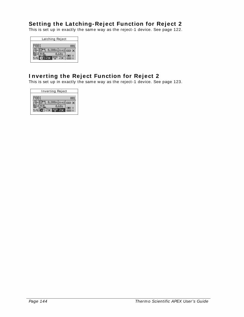
Page 144 Thermo Scientific APEX User’s Guide
Setting the Latching-Reject Function for Reject 2 This is set up in exactly the same way as the reject-1 device. See page 122.
Latching Reject
Inverting the Reject Function for Reject 2 This is set up in exactly the same way as the reject-1 device. See page 123.
Inverting Reject
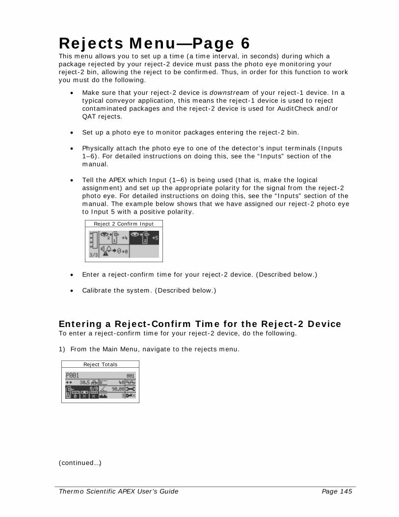
Thermo Scientific APEX User’s Guide Page 145
Rejects Menu—Page 6 This menu allows you to set up a time (a time interval, in seconds) during which a package rejected by your reject-2 device must pass the photo eye monitoring your reject-2 bin, allowing the reject to be confirmed. Thus, in order for this function to work you must do the following.
• Make sure that your reject-2 device is downstream of your reject-1 device. In a typical conveyor application, this means the reject-1 device is used to reject contaminated packages and the reject-2 device is used for AuditCheck and/or QAT rejects.
• Set up a photo eye to monitor packages entering the reject-2 bin.
• Physically attach the photo eye to one of the detector’s input terminals (Inputs 1–6). For detailed instructions on doing this, see the “Inputs” section of the manual.
• Tell the APEX which Input (1–6) is being used (that is, make the logical assignment) and set up the appropriate polarity for the signal from the reject-2 photo eye. For detailed instructions on doing this, see the “Inputs” section of the manual. The example below shows that we have assigned our reject-2 photo eye to Input 5 with a positive polarity.
Reject 2 Confirm Input
• Enter a reject-confirm time for your reject-2 device. (Described below.)
• Calibrate the system. (Described below.)
Entering a Reject-Confirm Time for the Reject-2 Device To enter a reject-confirm time for your reject-2 device, do the following. 1) From the Main Menu, navigate to the rejects menu.
Reject Totals
(continued…)
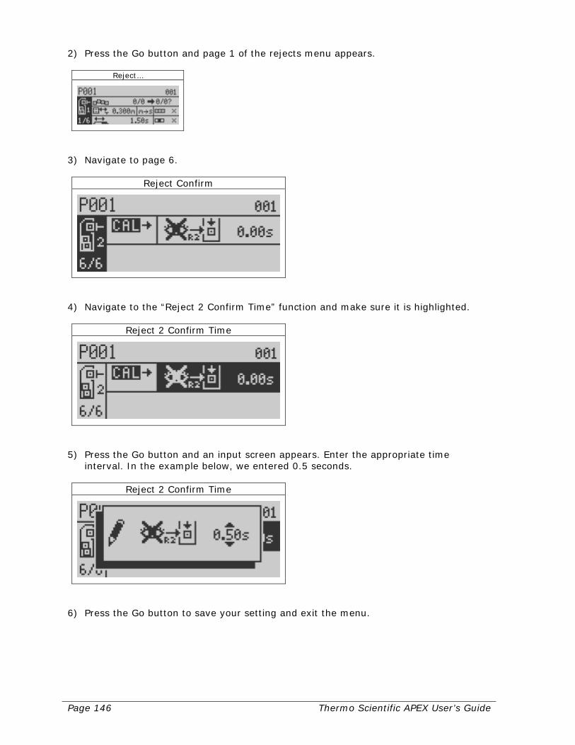
Page 146 Thermo Scientific APEX User’s Guide
2) Press the Go button and page 1 of the rejects menu appears.
Reject…
3) Navigate to page 6.
Reject Confirm
4) Navigate to the “Reject 2 Confirm Time” function and make sure it is highlighted.
Reject 2 Confirm Time
5) Press the Go button and an input screen appears. Enter the appropriate time
interval. In the example below, we entered 0.5 seconds.
Reject 2 Confirm Time
6) Press the Go button to save your setting and exit the menu.

Thermo Scientific APEX User’s Guide Page 147
Calibrating the Reject-2 Confirm Time In order to calibrate the reject 2 confirm time, that is, have the APEX set the appropriate time for you, you must do the following.
• Turn off your reject-1 device by going to the Outputs menu and setting the logically assigned value to X (off), as shown below. For detailed instructions on doing this, see the “Output” section of the manual. So, change the reject-1 output from this:
Output 1 Function
To this:
Output 1 Function
• Set your reject-2 device to reject contaminants during the calibration process.
(Described below.)
• Pass a contaminated package, so the reject-2 device can reject it, allowing the APEX to set the reject-2 confirm time. (Described below.)
• Turn your reject-1 device back on, which is a critical step! (Described below.) Calibration Procedure To calibrate the reject-2 confirm time, do the following. 1) Navigate to page 5 of the rejects menu, and highlight the “Reject 2 Contaminant”
menu.
Reject 2 Contaminant
(continued…)

Page 148 Thermo Scientific APEX User’s Guide
2) Press the Go button, and a checkmark appears next to the contaminant icon, which tells the reject-2 device to reject any contaminated packages.
Reject 2 Contaminant
3) Press the Back button to save your setting and exit the menu. 4) Navigate to page 6 of the rejects menu and make sure the calibration function is
highlighted.
Calibrate Reject Confirm Time
5) Press the Go button, and the following screen appears.
Calibrate Reject Confirm Time
6) Pass a contaminated package, so the reject-2 device can reject it, allowing the APEX
to set the reject-2 confirm time. When the calibration is complete the APEX closes this screen and displays the appropriate reject-2 confirm time.
(continued…)
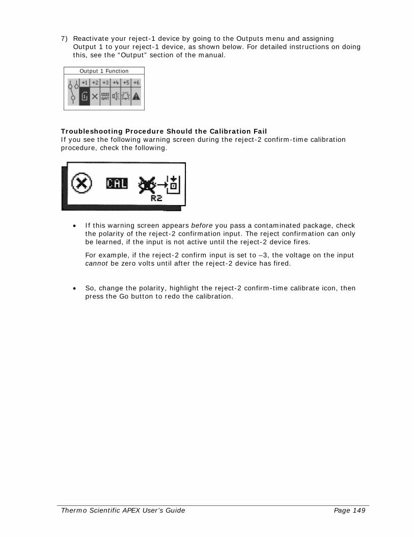
Thermo Scientific APEX User’s Guide Page 149
7) Reactivate your reject-1 device by going to the Outputs menu and assigning Output 1 to your reject-1 device, as shown below. For detailed instructions on doing this, see the “Output” section of the manual.
Output 1 Function
Troubleshooting Procedure Should the Calibration Fail If you see the following warning screen during the reject-2 confirm-time calibration procedure, check the following.
• If this warning screen appears before you pass a contaminated package, check the polarity of the reject-2 confirmation input. The reject confirmation can only be learned, if the input is not active until the reject-2 device fires.
For example, if the reject-2 confirm input is set to –3, the voltage on the input cannot be zero volts until after the reject-2 device has fired.
• So, change the polarity, highlight the reject-2 confirm-time calibrate icon, then press the Go button to redo the calibration.

Page 150 Thermo Scientific APEX User’s Guide
Phase Angle—Page 1 For a brief overview of what phase-angle is and its importance to the art and science of metal detection, see page 278. As a general rule, the following phase angles are representative of the following types of contaminants and non-contaminated products. Degrees Contaminant or non-contaminated product
+ 130 Metallic (ferrous) conductive contaminants, such as iron. + 90 Dry, non-conductive products, such as cereals and grains. + 65 Non-ferrous metallic contaminants, such as brass and aluminum. + 20–30 Metallic contaminants, such as 300-series stainless steel. 0 Wet, conductive products, such as fresh meats and breads.
Accessing the Phase Angle Menu To access the phase-angle menu, do the following. 1) From the Main Menu, use the navigation buttons to select the phase-angle menu.
Phase Angle
2) Press the Go button and page 1 of the phase-angle menu appears.
Phase Angle and Tracking
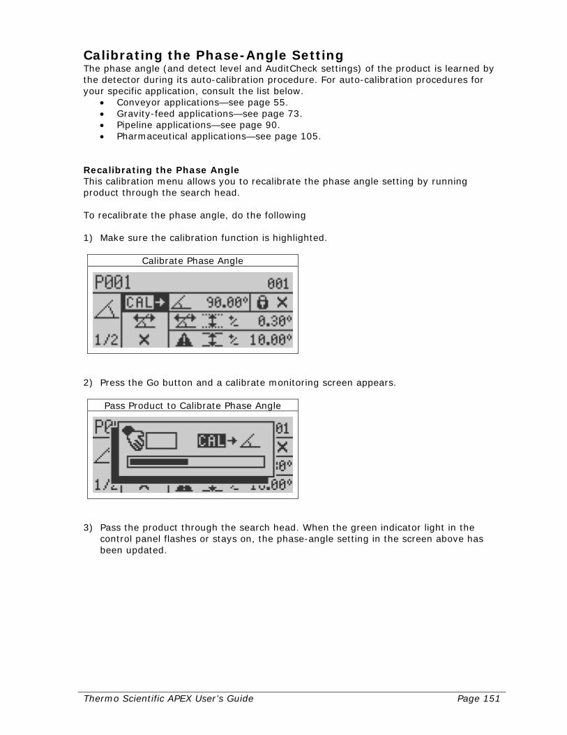
Thermo Scientific APEX User’s Guide Page 151
Calibrating the Phase-Angle Setting The phase angle (and detect level and AuditCheck settings) of the product is learned by the detector during its auto-calibration procedure. For auto-calibration procedures for your specific application, consult the list below.
• Conveyor applications—see page 55. • Gravity-feed applications—see page 73. • Pipeline applications—see page 90. • Pharmaceutical applications—see page 105.
Recalibrating the Phase Angle This calibration menu allows you to recalibrate the phase angle setting by running product through the search head. To recalibrate the phase angle, do the following 1) Make sure the calibration function is highlighted.
Calibrate Phase Angle
2) Press the Go button and a calibrate monitoring screen appears.
Pass Product to Calibrate Phase Angle
3) Pass the product through the search head. When the green indicator light in the
control panel flashes or stays on, the phase-angle setting in the screen above has been updated.
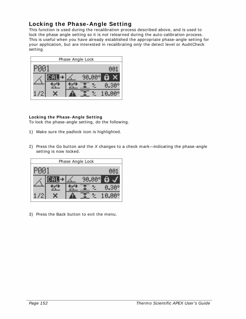
Page 152 Thermo Scientific APEX User’s Guide
Locking the Phase-Angle Setting This function is used during the recalibration process described above, and is used to lock the phase angle setting so it is not relearned during the auto-calibration process. This is useful when you have already established the appropriate phase-angle setting for your application, but are interested in recalibrating only the detect level or AuditCheck setting.
Phase Angle Lock
Locking the Phase-Angle Setting To lock the phase-angle setting, do the following. 1) Make sure the padlock icon is highlighted. 2) Press the Go button and the X changes to a check mark—indicating the phase-angle
setting is now locked.
Phase Angle Lock
3) Press the Back button to exit the menu.
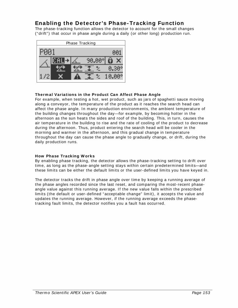
Thermo Scientific APEX User’s Guide Page 153
Enabling the Detector’s Phase-Tracking Function The phase-tracking function allows the detector to account for the small changes (“drift”) that occur in phase angle during a daily (or other long) production run.
Phase Tracking
Thermal Variations in the Product Can Affect Phase Angle For example, when testing a hot, wet product, such as jars of spaghetti sauce moving along a conveyor, the temperature of the product as it reaches the search head can affect the phase angle. In many production environments, the ambient temperature of the building changes throughout the day—for example, by becoming hotter in the afternoon as the sun heats the sides and roof of the building. This, in turn, causes the air temperature in the building to rise and the rate of cooling of the product to decrease during the afternoon. Thus, product entering the search head will be cooler in the morning and warmer in the afternoon, and this gradual change in temperature throughout the day can cause the phase angle to gradually change, or drift, during the daily production runs. How Phase Tracking Works By enabling phase tracking, the detector allows the phase-tracking setting to drift over time, as long as the phase-angle setting stays within certain predetermined limits—and these limits can be either the default limits or the user-defined limits you have keyed in. The detector tracks the drift in phase angle over time by keeping a running average of the phase angles recorded since the last reset, and comparing the most-recent phase-angle value against this running average. If the new value falls within the prescribed limits (the default or user-defined “acceptable change” limit), it accepts the value and updates the running average. However, if the running average exceeds the phase-tracking fault limits, the detector notifies you a fault has occurred.
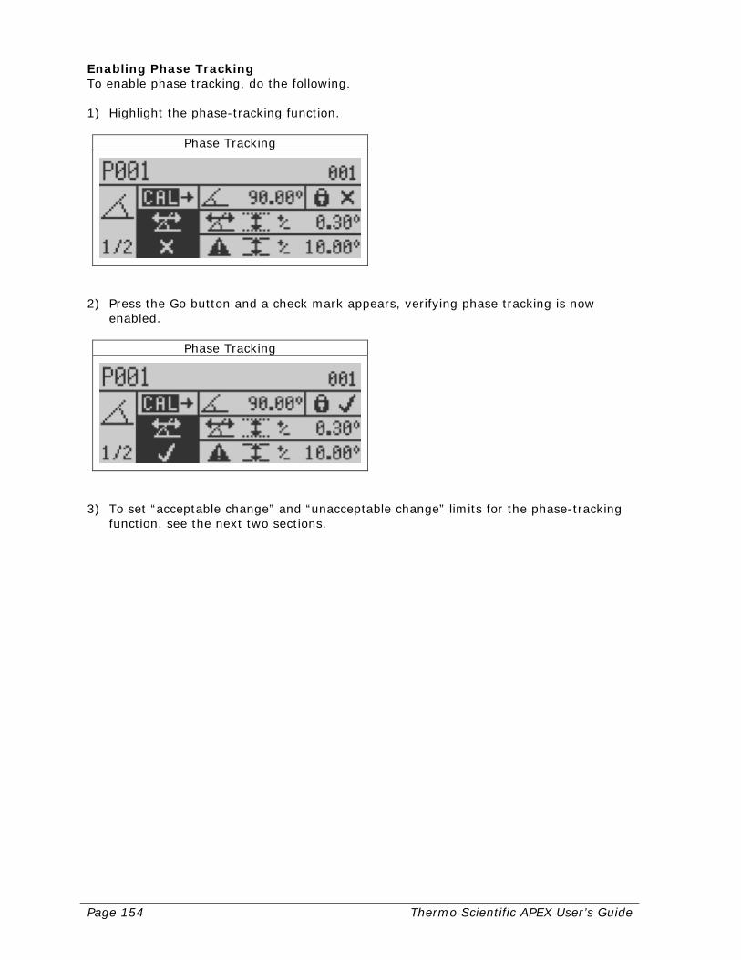
Page 154 Thermo Scientific APEX User’s Guide
Enabling Phase Tracking To enable phase tracking, do the following. 1) Highlight the phase-tracking function.
Phase Tracking
2) Press the Go button and a check mark appears, verifying phase tracking is now
enabled.
Phase Tracking
3) To set “acceptable change” and “unacceptable change” limits for the phase-tracking
function, see the next two sections.
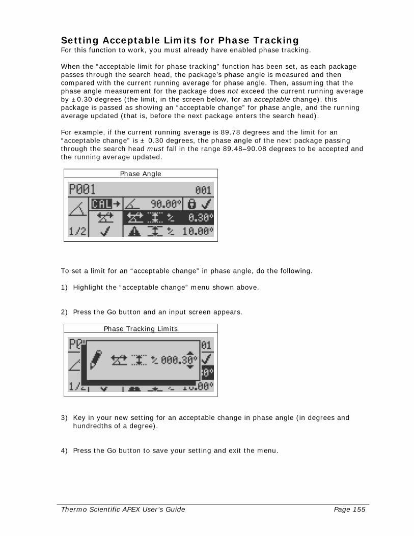
Thermo Scientific APEX User’s Guide Page 155
Setting Acceptable Limits for Phase Tracking For this function to work, you must already have enabled phase tracking. When the “acceptable limit for phase tracking” function has been set, as each package passes through the search head, the package’s phase angle is measured and then compared with the current running average for phase angle. Then, assuming that the phase angle measurement for the package does not exceed the current running average by ±0.30 degrees (the limit, in the screen below, for an acceptable change), this package is passed as showing an “acceptable change” for phase angle, and the running average updated (that is, before the next package enters the search head). For example, if the current running average is 89.78 degrees and the limit for an “acceptable change” is ± 0.30 degrees, the phase angle of the next package passing through the search head must fall in the range 89.48–90.08 degrees to be accepted and the running average updated.
Phase Angle
To set a limit for an “acceptable change” in phase angle, do the following. 1) Highlight the “acceptable change” menu shown above. 2) Press the Go button and an input screen appears.
Phase Tracking Limits
3) Key in your new setting for an acceptable change in phase angle (in degrees and
hundredths of a degree). 4) Press the Go button to save your setting and exit the menu.
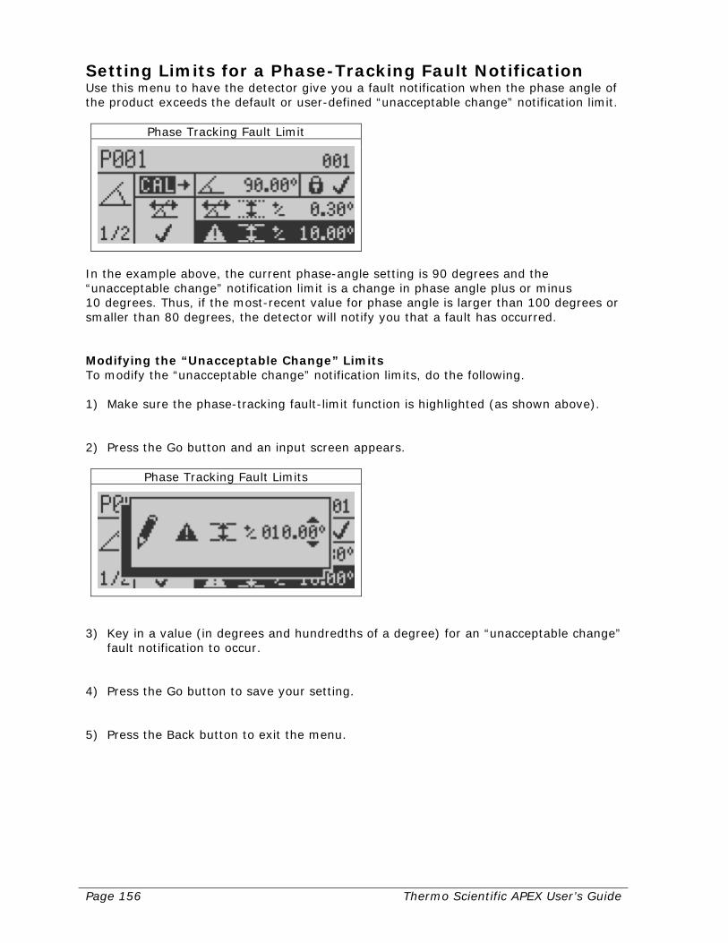
Page 156 Thermo Scientific APEX User’s Guide
Setting Limits for a Phase-Tracking Fault Notification Use this menu to have the detector give you a fault notification when the phase angle of the product exceeds the default or user-defined “unacceptable change” notification limit.
Phase Tracking Fault Limit
In the example above, the current phase-angle setting is 90 degrees and the “unacceptable change” notification limit is a change in phase angle plus or minus 10 degrees. Thus, if the most-recent value for phase angle is larger than 100 degrees or smaller than 80 degrees, the detector will notify you that a fault has occurred. Modifying the “Unacceptable Change” Limits To modify the “unacceptable change” notification limits, do the following. 1) Make sure the phase-tracking fault-limit function is highlighted (as shown above). 2) Press the Go button and an input screen appears.
Phase Tracking Fault Limits
3) Key in a value (in degrees and hundredths of a degree) for an “unacceptable change”
fault notification to occur. 4) Press the Go button to save your setting. 5) Press the Back button to exit the menu.
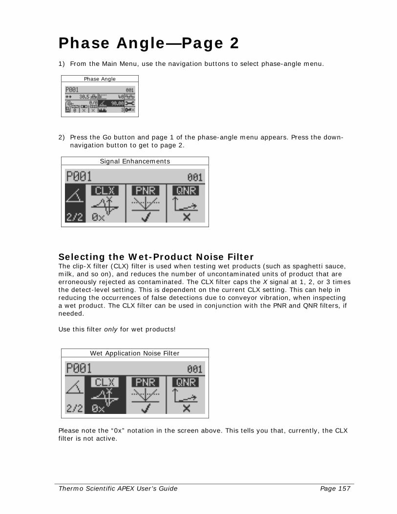
Thermo Scientific APEX User’s Guide Page 157
Phase Angle—Page 2 1) From the Main Menu, use the navigation buttons to select phase-angle menu.
Phase Angle
2) Press the Go button and page 1 of the phase-angle menu appears. Press the down-
navigation button to get to page 2.
Signal Enhancements
Selecting the Wet-Product Noise Filter The clip-X filter (CLX) filter is used when testing wet products (such as spaghetti sauce, milk, and so on), and reduces the number of uncontaminated units of product that are erroneously rejected as contaminated. The CLX filter caps the X signal at 1, 2, or 3 times the detect-level setting. This is dependent on the current CLX setting. This can help in reducing the occurrences of false detections due to conveyor vibration, when inspecting a wet product. The CLX filter can be used in conjunction with the PNR and QNR filters, if needed. Use this filter only for wet products!
Wet Application Noise Filter
Please note the “0x” notation in the screen above. This tells you that, currently, the CLX filter is not active.
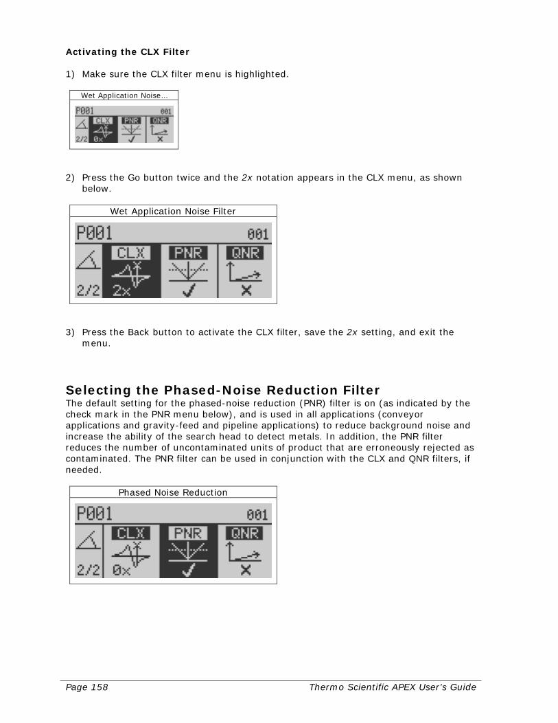
Page 158 Thermo Scientific APEX User’s Guide
Activating the CLX Filter 1) Make sure the CLX filter menu is highlighted.
Wet Application Noise…
2) Press the Go button twice and the 2x notation appears in the CLX menu, as shown
below.
Wet Application Noise Filter
3) Press the Back button to activate the CLX filter, save the 2x setting, and exit the
menu.
Selecting the Phased-Noise Reduction Filter The default setting for the phased-noise reduction (PNR) filter is on (as indicated by the check mark in the PNR menu below), and is used in all applications (conveyor applications and gravity-feed and pipeline applications) to reduce background noise and increase the ability of the search head to detect metals. In addition, the PNR filter reduces the number of uncontaminated units of product that are erroneously rejected as contaminated. The PNR filter can be used in conjunction with the CLX and QNR filters, if needed.
Phased Noise Reduction
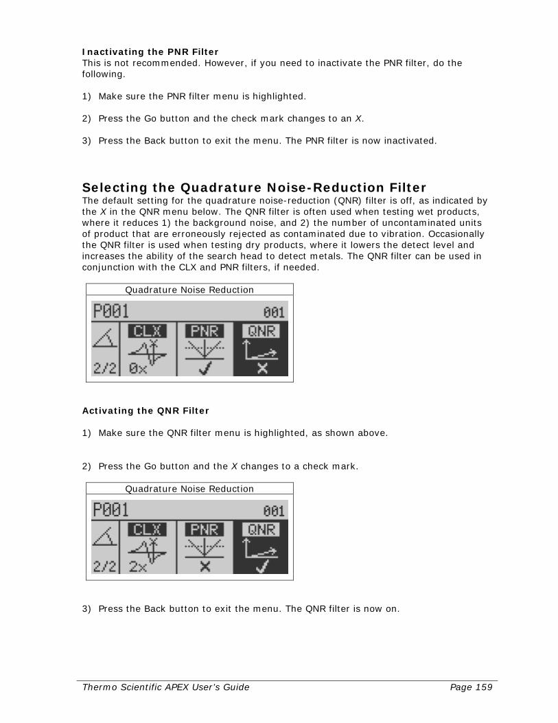
Thermo Scientific APEX User’s Guide Page 159
Inactivating the PNR Filter This is not recommended. However, if you need to inactivate the PNR filter, do the following. 1) Make sure the PNR filter menu is highlighted. 2) Press the Go button and the check mark changes to an X. 3) Press the Back button to exit the menu. The PNR filter is now inactivated.
Selecting the Quadrature Noise-Reduction Filter The default setting for the quadrature noise-reduction (QNR) filter is off, as indicated by the X in the QNR menu below. The QNR filter is often used when testing wet products, where it reduces 1) the background noise, and 2) the number of uncontaminated units of product that are erroneously rejected as contaminated due to vibration. Occasionally the QNR filter is used when testing dry products, where it lowers the detect level and increases the ability of the search head to detect metals. The QNR filter can be used in conjunction with the CLX and PNR filters, if needed.
Quadrature Noise Reduction
Activating the QNR Filter 1) Make sure the QNR filter menu is highlighted, as shown above. 2) Press the Go button and the X changes to a check mark.
Quadrature Noise Reduction
3) Press the Back button to exit the menu. The QNR filter is now on.
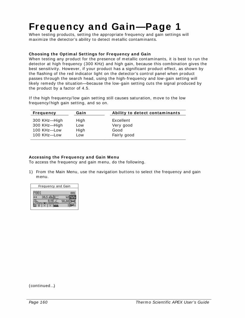
Page 160 Thermo Scientific APEX User’s Guide
Frequency and Gain—Page 1 When testing products, setting the appropriate frequency and gain settings will maximize the detector’s ability to detect metallic contaminants. Choosing the Optimal Settings for Frequency and Gain When testing any product for the presence of metallic contaminants, it is best to run the detector at high frequency (300 KHz) and high gain, because this combination gives the best sensitivity. However, if your product has a significant product effect, as shown by the flashing of the red indicator light on the detector’s control panel when product passes through the search head, using the high-frequency and low-gain setting will likely remedy the situation—because the low-gain setting cuts the signal produced by the product by a factor of 4.5. If the high frequency/low gain setting still causes saturation, move to the low frequency/high gain setting, and so on.
Frequency Gain Ability to detect contaminants
300 KHz—High High Excellent 300 KHz—High Low Very good 100 KHz—Low High Good 100 KHz—Low Low Fairly good
Accessing the Frequency and Gain Menu To access the frequency and gain menu, do the following. 1) From the Main Menu, use the navigation buttons to select the frequency and gain
menu.
Frequency and Gain
(continued…)

Thermo Scientific APEX User’s Guide Page 161
2) Press the Go button and page 1 of the frequency and gain menu appears.
Frequency, Gain & Inhibit
The frequency and gain icons shown in this menu are as follows.
High frequency
Low frequency
High gain
Low gain
Currently, the detector (as shown in the figure above) is set on high frequency and high gain—the default setting.
Setting High or Low Frequency As indicated in the figure below, the detector is currently set on high frequency.
Low/High Frequency
1) To change to low frequency, press the Go button and a check mark appears next to
the low-frequency icon (and an X appears next to the high-frequency icon).
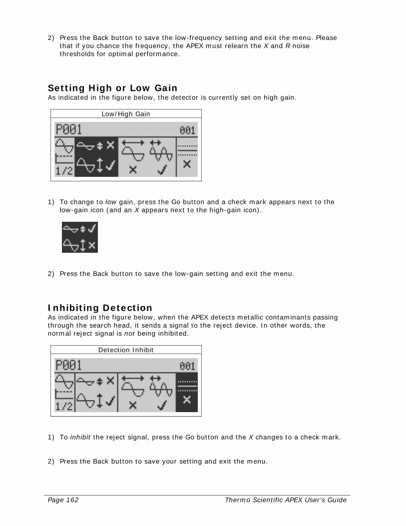
Page 162 Thermo Scientific APEX User’s Guide
2) Press the Back button to save the low-frequency setting and exit the menu. Please that if you chance the frequency, the APEX must relearn the X and R noise thresholds for optimal performance.
Setting High or Low Gain As indicated in the figure below, the detector is currently set on high gain.
Low/High Gain
1) To change to low gain, press the Go button and a check mark appears next to the
low-gain icon (and an X appears next to the high-gain icon).
2) Press the Back button to save the low-gain setting and exit the menu.
Inhibiting Detection As indicated in the figure below, when the APEX detects metallic contaminants passing through the search head, it sends a signal to the reject device. In other words, the normal reject signal is not being inhibited.
Detection Inhibit
1) To inhibit the reject signal, press the Go button and the X changes to a check mark. 2) Press the Back button to save your setting and exit the menu.
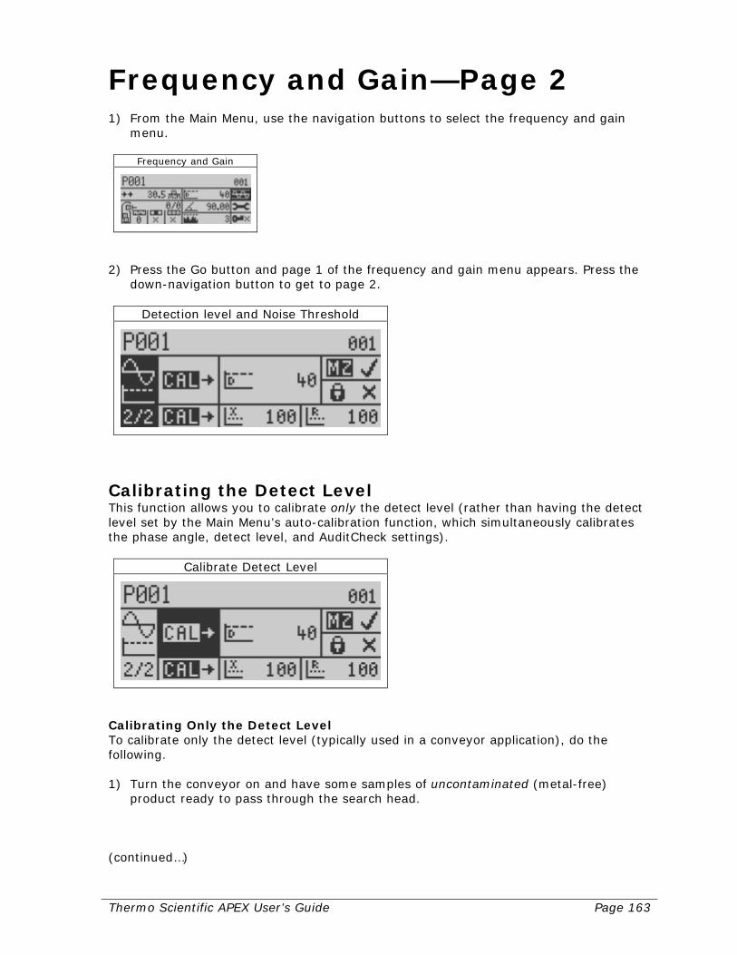
Thermo Scientific APEX User’s Guide Page 163
Frequency and Gain—Page 2 1) From the Main Menu, use the navigation buttons to select the frequency and gain
menu.
Frequency and Gain
2) Press the Go button and page 1 of the frequency and gain menu appears. Press the
down-navigation button to get to page 2.
Detection level and Noise Threshold
Calibrating the Detect Level This function allows you to calibrate only the detect level (rather than having the detect level set by the Main Menu’s auto-calibration function, which simultaneously calibrates the phase angle, detect level, and AuditCheck settings).
Calibrate Detect Level
Calibrating Only the Detect Level To calibrate only the detect level (typically used in a conveyor application), do the following. 1) Turn the conveyor on and have some samples of uncontaminated (metal-free)
product ready to pass through the search head. (continued…)
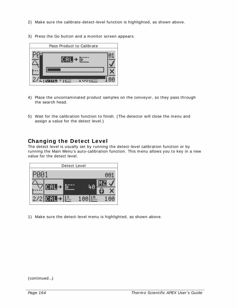
Page 164 Thermo Scientific APEX User’s Guide
2) Make sure the calibrate-detect-level function is highlighted, as shown above. 3) Press the Go button and a monitor screen appears.
Pass Product to Calibrate
4) Place the uncontaminated product samples on the conveyor, so they pass through
the search head. 5) Wait for the calibration function to finish. (The detector will close the menu and
assign a value for the detect level.)
Changing the Detect Level The detect level is usually set by running the detect-level calibration function or by running the Main Menu’s auto-calibration function. This menu allows you to key in a new value for the detect level.
Detect Level
1) Make sure the detect-level menu is highlighted, as shown above. (continued…)
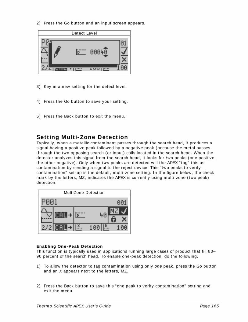
Thermo Scientific APEX User’s Guide Page 165
2) Press the Go button and an input screen appears.
Detect Level
3) Key in a new setting for the detect level. 4) Press the Go button to save your setting. 5) Press the Back button to exit the menu.
Setting Multi-Zone Detection Typically, when a metallic contaminant passes through the search head, it produces a signal having a positive peak followed by a negative peak (because the metal passes through the two opposing search (or input) coils located in the search head. When the detector analyzes this signal from the search head, it looks for two peaks (one positive, the other negative). Only when two peaks are detected will the APEX “tag” this as contamination by sending a signal to the reject device. This “two peaks to verify contamination” set-up is the default, multi-zone setting. In the figure below, the check mark by the letters, MZ, indicates the APEX is currently using multi-zone (two peak) detection.
MultiZone Detection
Enabling One-Peak Detection This function is typically used in applications running large cases of product that fill 80–90 percent of the search head. To enable one-peak detection, do the following. 1) To allow the detector to tag contamination using only one peak, press the Go button
and an X appears next to the letters, MZ. 2) Press the Back button to save this “one peak to verify contamination” setting and
exit the menu.
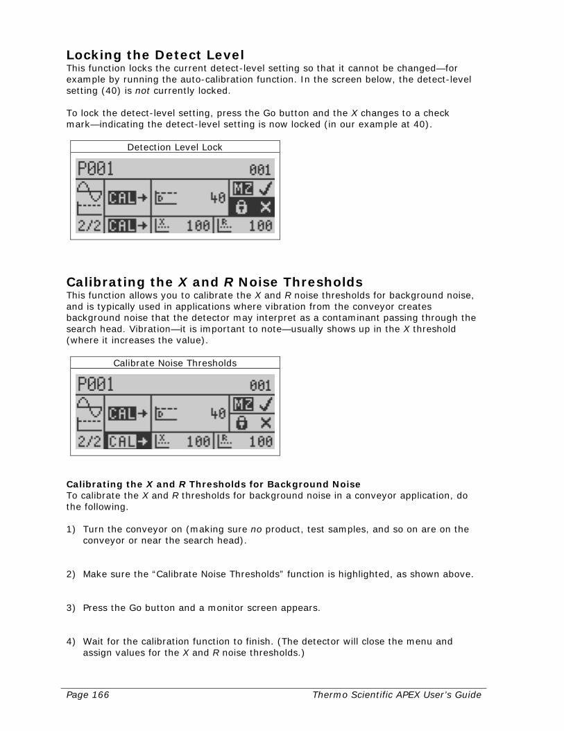
Page 166 Thermo Scientific APEX User’s Guide
Locking the Detect Level This function locks the current detect-level setting so that it cannot be changed—for example by running the auto-calibration function. In the screen below, the detect-level setting (40) is not currently locked. To lock the detect-level setting, press the Go button and the X changes to a check mark—indicating the detect-level setting is now locked (in our example at 40).
Detection Level Lock
Calibrating the X and R Noise Thresholds This function allows you to calibrate the X and R noise thresholds for background noise, and is typically used in applications where vibration from the conveyor creates background noise that the detector may interpret as a contaminant passing through the search head. Vibration—it is important to note—usually shows up in the X threshold (where it increases the value).
Calibrate Noise Thresholds
Calibrating the X and R Thresholds for Background Noise To calibrate the X and R thresholds for background noise in a conveyor application, do the following. 1) Turn the conveyor on (making sure no product, test samples, and so on are on the
conveyor or near the search head). 2) Make sure the “Calibrate Noise Thresholds” function is highlighted, as shown above. 3) Press the Go button and a monitor screen appears. 4) Wait for the calibration function to finish. (The detector will close the menu and
assign values for the X and R noise thresholds.)

Thermo Scientific APEX User’s Guide Page 167
Changing the Noise Threshold for X In conveyor applications, the noise threshold for X is often increased to prevent the detector interpreting vibration as contamination.
X Threshold
To change the noise threshold for X, do the following. 1) Make sure the X-threshold menu is highlighted. 2) Press the Go button and an input screen appears. 3) Key in a new setting for the X noise threshold. 4) Press the Go button to save your setting 5) Press the Back button to exit the menu.
Changing the Noise Threshold for R
R Threshold
To change the noise threshold for R, do the following. 1) Make sure the R-threshold menu is highlighted. 2) Press the Go button and an input screen appears. 3) Key in a new setting for the R noise threshold. 4) Press the Go button to save your setting. 5) Press the Back button to exit the menu.

Page 168 Thermo Scientific APEX User’s Guide
System and Tools—Page 1 1) From the Main Menu navigate to the system and tools menu.
System and Tools
2) Press the Go button and page 1 of the system and tools menu appears.
System and Tools Page 1
Quality Test See page 196.
Quality Test
AuditCheck See page 206.
AuditCheck
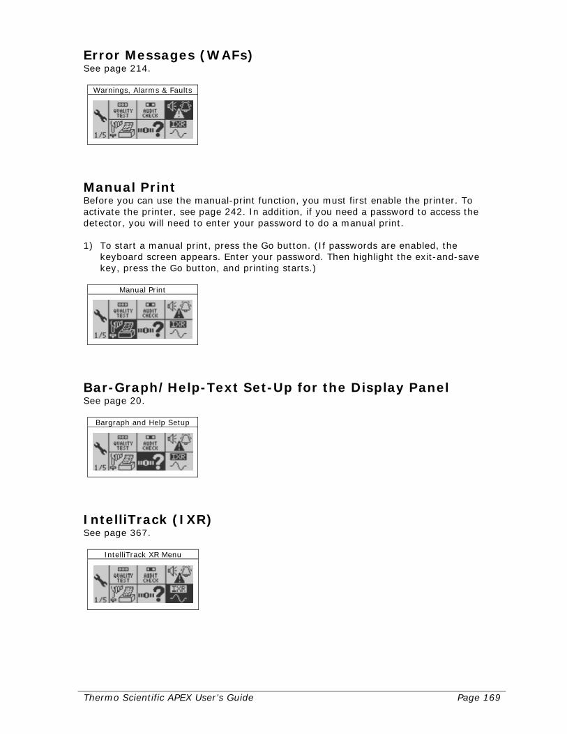
Thermo Scientific APEX User’s Guide Page 169
Error Messages (WAFs) See page 214.
Warnings, Alarms & Faults
Manual Print Before you can use the manual-print function, you must first enable the printer. To activate the printer, see page 242. In addition, if you need a password to access the detector, you will need to enter your password to do a manual print. 1) To start a manual print, press the Go button. (If passwords are enabled, the
keyboard screen appears. Enter your password. Then highlight the exit-and-save key, press the Go button, and printing starts.)
Manual Print
Bar-Graph/Help-Text Set-Up for the Display Panel See page 20.
Bargraph and Help Setup
IntelliTrack (IXR) See page 367.
IntelliTrack XR Menu
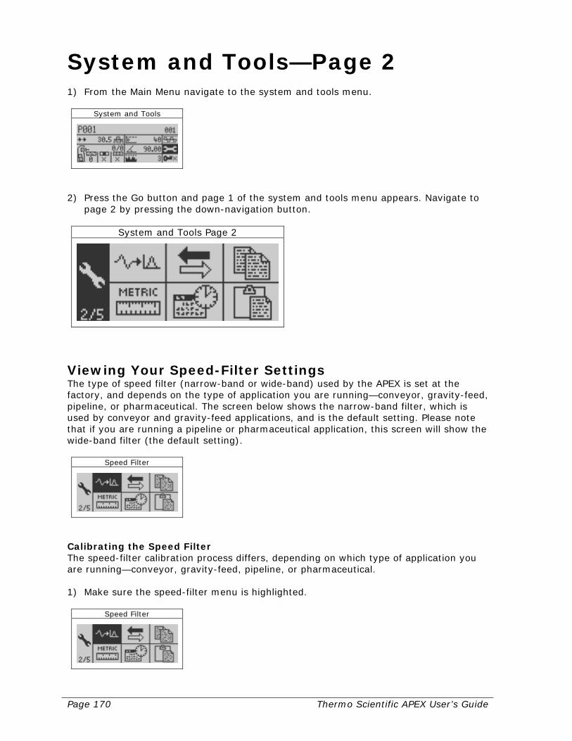
Page 170 Thermo Scientific APEX User’s Guide
System and Tools—Page 2 1) From the Main Menu navigate to the system and tools menu.
System and Tools
2) Press the Go button and page 1 of the system and tools menu appears. Navigate to
page 2 by pressing the down-navigation button.
System and Tools Page 2
Viewing Your Speed-Filter Settings The type of speed filter (narrow-band or wide-band) used by the APEX is set at the factory, and depends on the type of application you are running—conveyor, gravity-feed, pipeline, or pharmaceutical. The screen below shows the narrow-band filter, which is used by conveyor and gravity-feed applications, and is the default setting. Please note that if you are running a pipeline or pharmaceutical application, this screen will show the wide-band filter (the default setting).
Speed Filter
Calibrating the Speed Filter The speed-filter calibration process differs, depending on which type of application you are running—conveyor, gravity-feed, pipeline, or pharmaceutical. 1) Make sure the speed-filter menu is highlighted.
Speed Filter
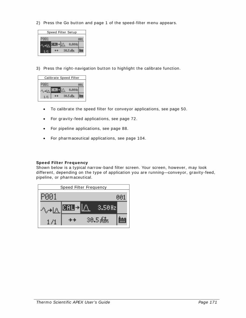
Thermo Scientific APEX User’s Guide Page 171
2) Press the Go button and page 1 of the speed-filter menu appears.
Speed Filter Setup
3) Press the right-navigation button to highlight the calibrate function.
Calibrate Speed Filter
• To calibrate the speed filter for conveyor applications, see page 50. • For gravity-feed applications, see page 72. • For pipeline applications, see page 88. • For pharmaceutical applications, see page 104.
Speed Filter Frequency Shown below is a typical narrow-band filter screen. Your screen, however, may look different, depending on the type of application you are running—conveyor, gravity-feed, pipeline, or pharmaceutical.
Speed Filter Frequency
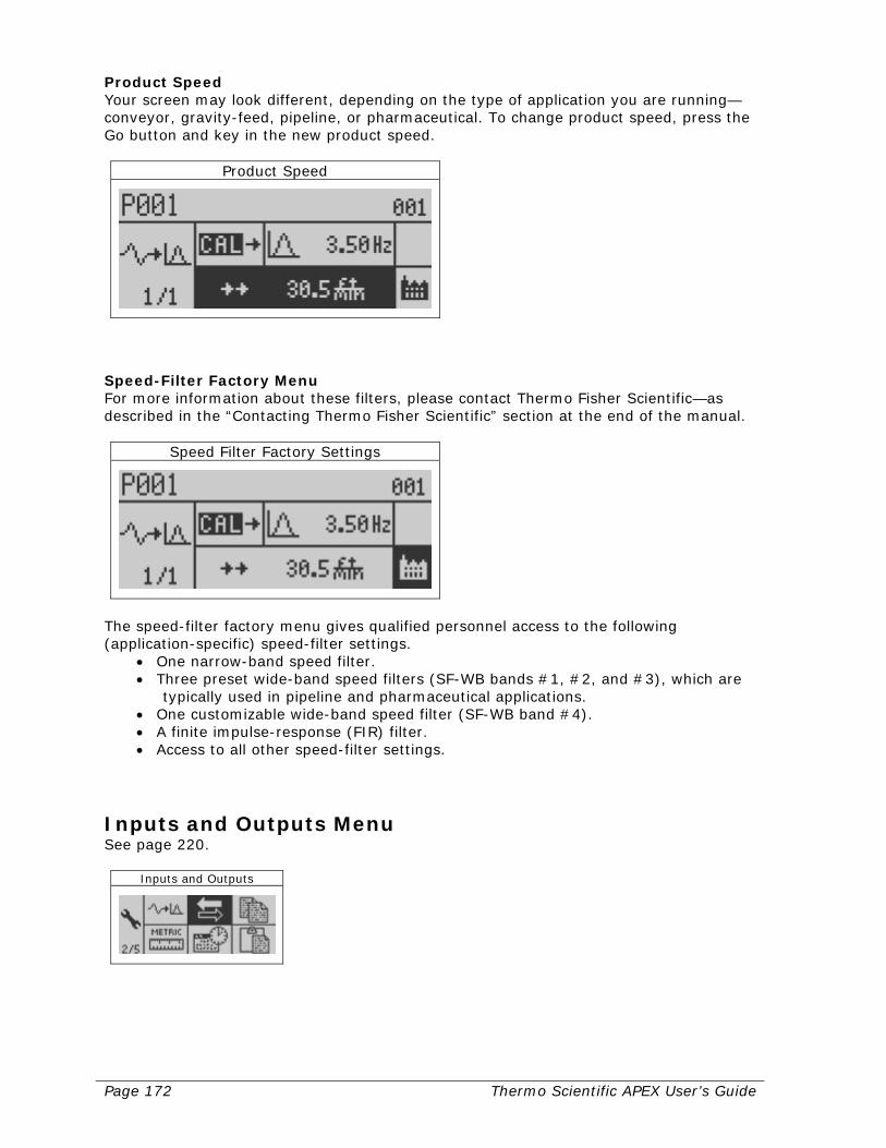
Page 172 Thermo Scientific APEX User’s Guide
Product Speed Your screen may look different, depending on the type of application you are running—conveyor, gravity-feed, pipeline, or pharmaceutical. To change product speed, press the Go button and key in the new product speed.
Product Speed
Speed-Filter Factory Menu For more information about these filters, please contact Thermo Fisher Scientific—as described in the “Contacting Thermo Fisher Scientific” section at the end of the manual.
Speed Filter Factory Settings
The speed-filter factory menu gives qualified personnel access to the following (application-specific) speed-filter settings.
• One narrow-band speed filter. • Three preset wide-band speed filters (SF-WB bands #1, #2, and #3), which are
typically used in pipeline and pharmaceutical applications. • One customizable wide-band speed filter (SF-WB band #4). • A finite impulse-response (FIR) filter. • Access to all other speed-filter settings.
Inputs and Outputs Menu See page 220.
Inputs and Outputs
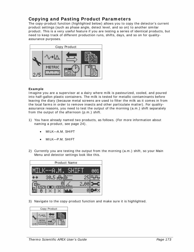
Thermo Scientific APEX User’s Guide Page 173
Copying and Pasting Product Parameters The copy-product function (highlighted below) allows you to copy the detector’s current product settings (such as phase angle, detect level, and so on) to another similar product. This is a very useful feature if you are testing a series of identical products, but need to keep track of different production runs, shifts, days, and so on for quality-assurance purposes.
Copy Product
Example Imagine you are a supervisor at a dairy where milk is pasteurized, cooled, and poured into half-gallon plastic containers. The milk is tested for metallic contaminants before leaving the diary (because metal screens are used to filter the milk as it comes in from the local farms in order to remove insects and other particulate matter). For quality-assurance reasons, you need to test the output of the morning (a.m.) shift separately from the output of the afternoon (p.m.) shift. 1) You have already named two products, as follows. (For more information about
naming a product, see page 24). • MILK—A.M. SHIFT • MILK—P.M. SHIFT
2) Currently you are testing the output from the morning (a.m.) shift, so your Main
Menu and detector settings look like this.
Product Name
3) Navigate to the copy-product function and make sure it is highlighted.
Copy Product
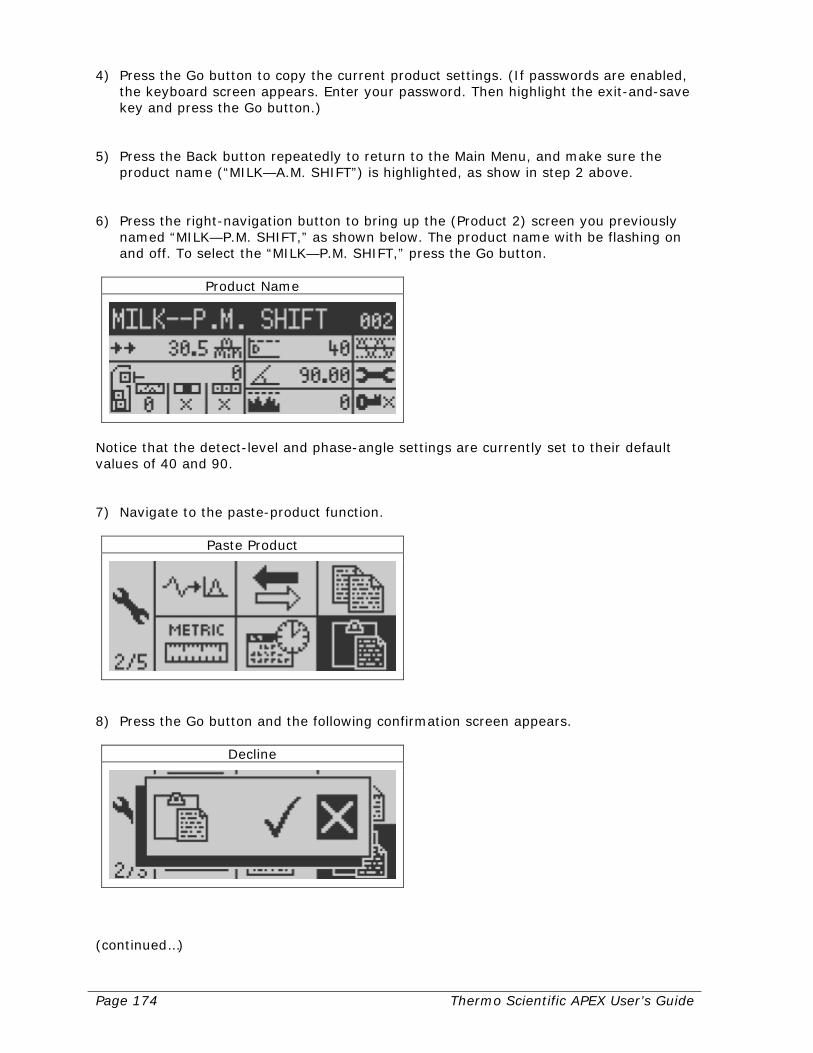
Page 174 Thermo Scientific APEX User’s Guide
4) Press the Go button to copy the current product settings. (If passwords are enabled, the keyboard screen appears. Enter your password. Then highlight the exit-and-save key and press the Go button.)
5) Press the Back button repeatedly to return to the Main Menu, and make sure the
product name (“MILK—A.M. SHIFT”) is highlighted, as show in step 2 above. 6) Press the right-navigation button to bring up the (Product 2) screen you previously
named “MILK—P.M. SHIFT,” as shown below. The product name with be flashing on and off. To select the “MILK—P.M. SHIFT,” press the Go button.
Product Name
Notice that the detect-level and phase-angle settings are currently set to their default values of 40 and 90. 7) Navigate to the paste-product function.
Paste Product
8) Press the Go button and the following confirmation screen appears.
Decline
(continued…)

Thermo Scientific APEX User’s Guide Page 175
9) Press the left-navigation button to select the “Accept” check mark.
Accept
10) Press the Go button. (The detector pastes in the product parameters and closes the
confirmation screen.) 11) Press the Back button repeatedly to return to the Main Menu, which should now
look like this.
Product Name
Notice that the initial setting for detect level and phase angle for the “MILK—P.M. SHIFT” (shown in step 6, where the settings were 40 and 90, respectively) have changed, and now match those for the “MILK—A.M. SHIFT” (25 and 2, respectively, as shown in the screen in step 2 above). Summary All “MILK—A.M. SHIFT” parameters have now been copied to the “MILK—P.M. SHIFT.” Clearly, by using copy and paste, you have made a substantial saving in time and effort in comparison to the alternative—re-entering the product parameters, re-running the calibrations, and so on.
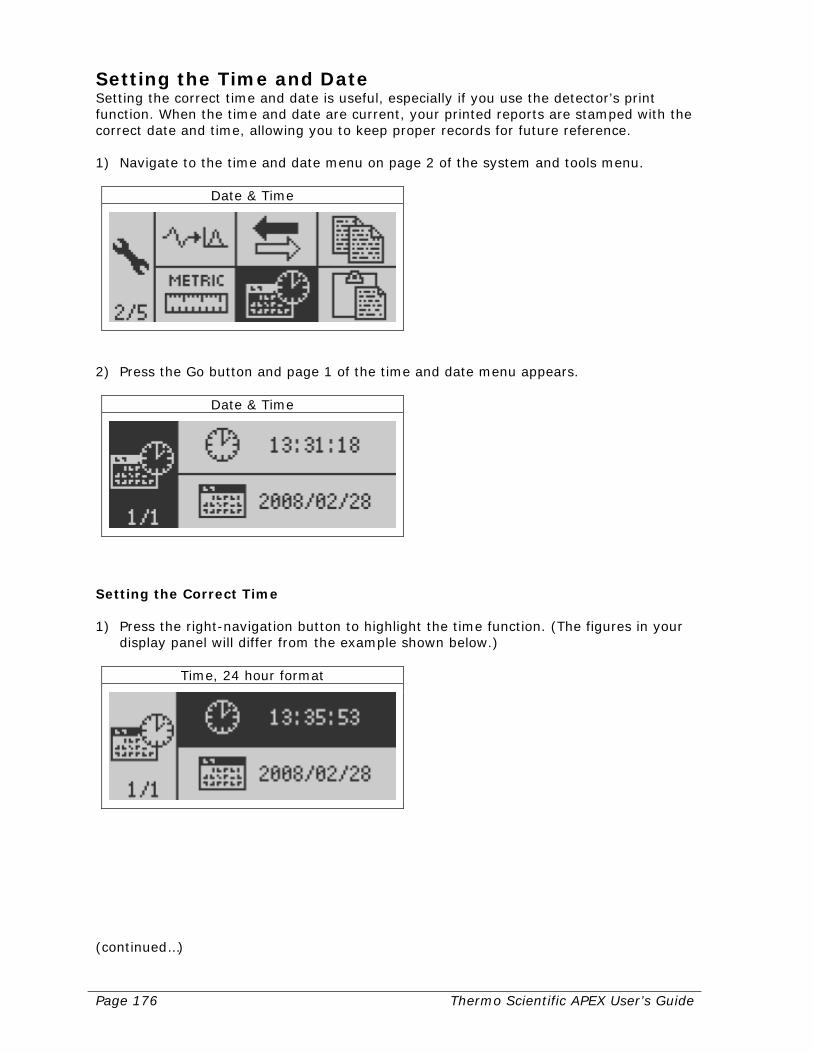
Page 176 Thermo Scientific APEX User’s Guide
Setting the Time and Date Setting the correct time and date is useful, especially if you use the detector’s print function. When the time and date are current, your printed reports are stamped with the correct date and time, allowing you to keep proper records for future reference. 1) Navigate to the time and date menu on page 2 of the system and tools menu.
Date & Time
2) Press the Go button and page 1 of the time and date menu appears.
Date & Time
Setting the Correct Time 1) Press the right-navigation button to highlight the time function. (The figures in your
display panel will differ from the example shown below.)
Time, 24 hour format
(continued…)
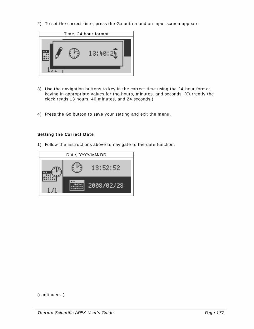
Thermo Scientific APEX User’s Guide Page 177
2) To set the correct time, press the Go button and an input screen appears.
Time, 24 hour format
3) Use the navigation buttons to key in the correct time using the 24-hour format,
keying in appropriate values for the hours, minutes, and seconds. (Currently the clock reads 13 hours, 40 minutes, and 24 seconds.)
4) Press the Go button to save your setting and exit the menu. Setting the Correct Date 1) Follow the instructions above to navigate to the date function.
Date, YYYY/MM/DD
(continued…)
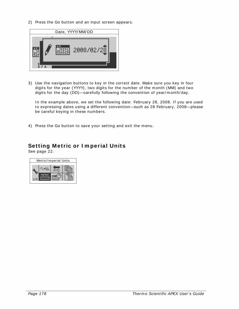
Page 178 Thermo Scientific APEX User’s Guide
2) Press the Go button and an input screen appears.
Date, YYYY/MM/DD
3) Use the navigation buttons to key in the correct date. Make sure you key in four
digits for the year (YYYY), two digits for the number of the month (MM) and two digits for the day (DD)—carefully following the convention of year/month/day. In the example above, we set the following date: February 28, 2008. If you are used to expressing dates using a different convention—such as 28 February, 2008—please be careful keying in these numbers.
4) Press the Go button to save your setting and exit the menu.
Setting Metric or Imperial Units See page 22.
Metric/Imperial Units
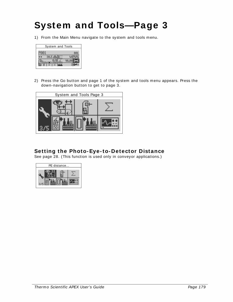
Thermo Scientific APEX User’s Guide Page 179
System and Tools—Page 3 1) From the Main Menu navigate to the system and tools menu.
System and Tools
2) Press the Go button and page 1 of the system and tools menu appears. Press the
down-navigation button to get to page 3.
System and Tools Page 3
Setting the Photo-Eye-to-Detector Distance See page 28. (This function is used only in conveyor applications.)
PE distance…
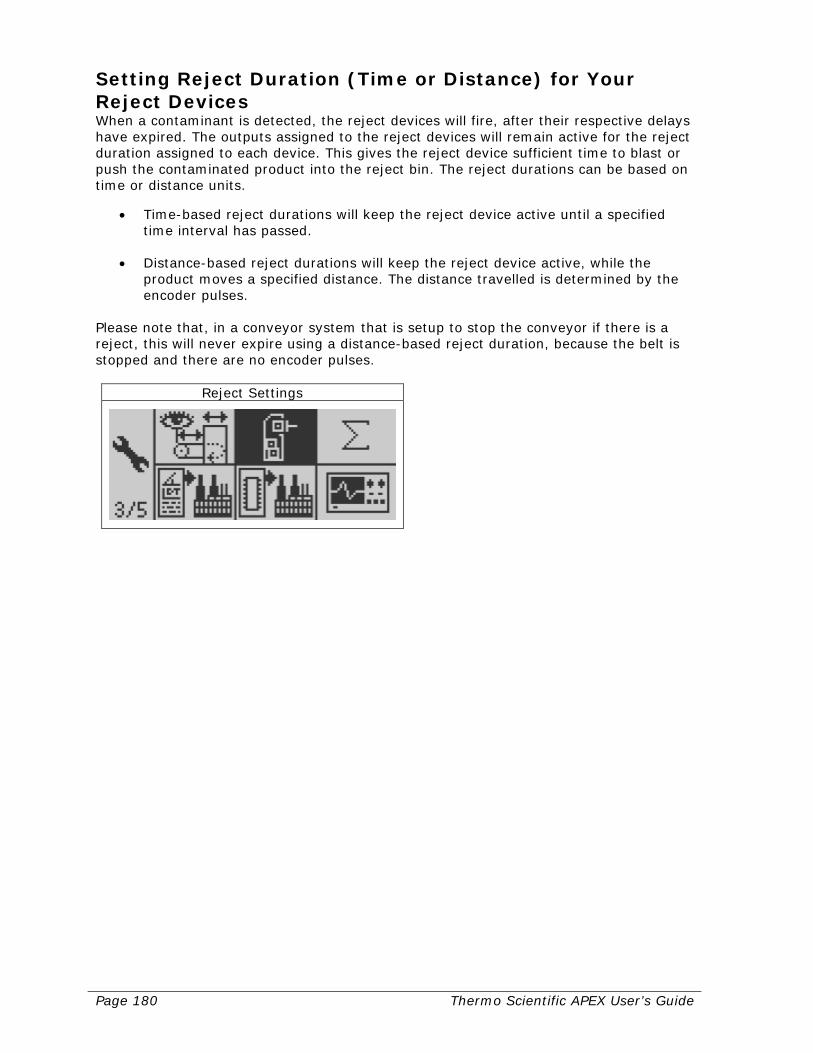
Page 180 Thermo Scientific APEX User’s Guide
Setting Reject Duration (Time or Distance) for Your Reject Devices When a contaminant is detected, the reject devices will fire, after their respective delays have expired. The outputs assigned to the reject devices will remain active for the reject duration assigned to each device. This gives the reject device sufficient time to blast or push the contaminated product into the reject bin. The reject durations can be based on time or distance units.
• Time-based reject durations will keep the reject device active until a specified time interval has passed.
• Distance-based reject durations will keep the reject device active, while the
product moves a specified distance. The distance travelled is determined by the encoder pulses.
Please note that, in a conveyor system that is setup to stop the conveyor if there is a reject, this will never expire using a distance-based reject duration, because the belt is stopped and there are no encoder pulses.
Reject Settings
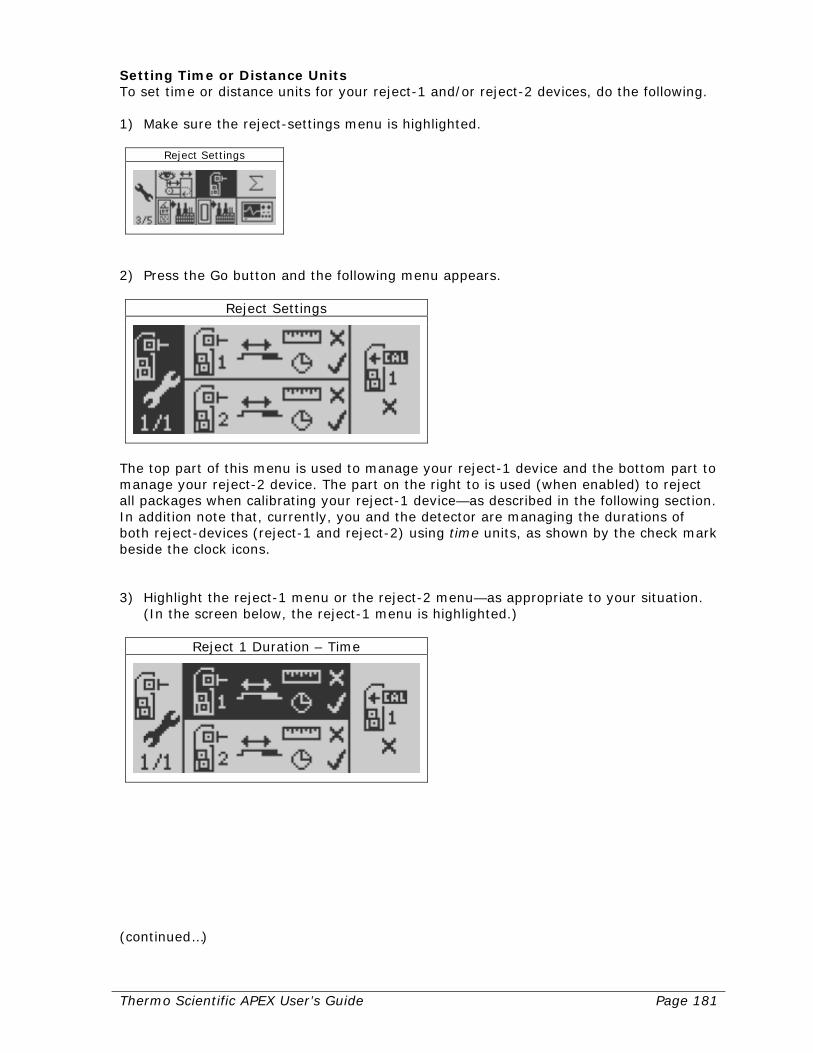
Thermo Scientific APEX User’s Guide Page 181
Setting Time or Distance Units To set time or distance units for your reject-1 and/or reject-2 devices, do the following. 1) Make sure the reject-settings menu is highlighted.
Reject Settings
2) Press the Go button and the following menu appears.
Reject Settings
The top part of this menu is used to manage your reject-1 device and the bottom part to manage your reject-2 device. The part on the right to is used (when enabled) to reject all packages when calibrating your reject-1 device—as described in the following section. In addition note that, currently, you and the detector are managing the durations of both reject-devices (reject-1 and reject-2) using time units, as shown by the check mark beside the clock icons. 3) Highlight the reject-1 menu or the reject-2 menu—as appropriate to your situation.
(In the screen below, the reject-1 menu is highlighted.)
Reject 1 Duration – Time
(continued…)

Page 182 Thermo Scientific APEX User’s Guide
4) Press the Go button, and the check mark moves to the distance (ruler) icon.
Reject 1 Duration – Distance
5) Press the Back button to exit the menu and save your distance preference for
managing the reject-1 device. The APEX will now use distance settings in all relevant reject-1 (or, if selected in step 3 above, reject-2) menus.
Setting the “Reject Packs During Learn” Function If you want all packages to be rejected during a calibration learn, you need to enable the “Reject Packs During Learn” function. To enable this function, do the following. 1) Highlight the “Reject Packs During Learn” menu.
Reject Packs During Learn
2) Press the Go button. A checkmark appears, showing this function is now enabled.
Reject Packs During Learn
3) Press the Back button to save your setting and exit the menu.
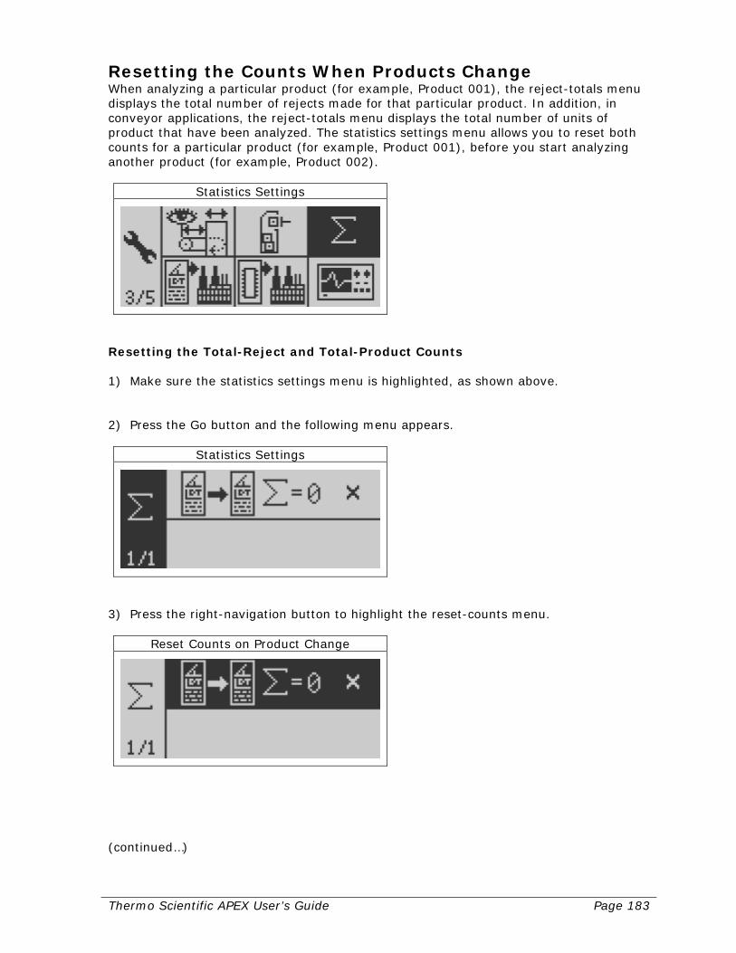
Thermo Scientific APEX User’s Guide Page 183
Resetting the Counts When Products Change When analyzing a particular product (for example, Product 001), the reject-totals menu displays the total number of rejects made for that particular product. In addition, in conveyor applications, the reject-totals menu displays the total number of units of product that have been analyzed. The statistics settings menu allows you to reset both counts for a particular product (for example, Product 001), before you start analyzing another product (for example, Product 002).
Statistics Settings
Resetting the Total-Reject and Total-Product Counts 1) Make sure the statistics settings menu is highlighted, as shown above. 2) Press the Go button and the following menu appears.
Statistics Settings
3) Press the right-navigation button to highlight the reset-counts menu.
Reset Counts on Product Change
(continued…)

Page 184 Thermo Scientific APEX User’s Guide
4) Press the Go button and the X changed to a check mark.
Reset Counts on Product Change
5) Press the Back button repeatedly to return to the Main Menu. The total-reject count
is now reset to zero. In addition, for conveyor applications, the total-product count is also reset to zero, as shown below.
Reject Totals
Resetting Product Parameters to the Default Settings This function allows you to reset the product-related parameters for a particular product. In other words, the product parameters for all other products remain unchanged.
Reset Product to Defaults
Example Imagine you are a supervisor at a dairy where you test salted butter, ice cream, and milk for the presence of metallic contaminants. You have been testing three products recently (named “SALTED BUTTER”, “ICE CREAM”, and “MILK”), and now want to reset the product parameters for “MILK” to the detector’s defaults settings. (continued…)

Thermo Scientific APEX User’s Guide Page 185
1) In the Main Menu make sure the product named “MILK” (Product 003) is highlighted. (Notice in our example that the detect level is currently set to 25, and the phase angle to 2.)
Product Name
2) Navigate to the reset-product-parameters function and make sure it is highlighted. 3) Press the Go button and a confirmation screen appears.
Decline
4) Press the left-navigation button to select the “Accept” check mark.
Accept
(continued…)

Page 186 Thermo Scientific APEX User’s Guide
5) Press the Go button. The detector resets the product parameters—including deleting the name “MILK”—and returns you to the Main Menu.
Product Name
Notice that all parameters for Product 003 have now been reset to their factory defaults. The detect level, for example, has been reset to 40 and phase angle to 90.
Resetting the NVRAM Parameters to the Default Settings This function resets virtually everything in the detector to its factory-default settings. Only supervisors can enter this function. However, do not enter this function unless you are firmly resolved to delete all your product and other settings and start afresh. This function clears everything from the detector’s memory—except the model of APEX (500, 300, or 100) and type of application (conveyor application, gravity-feed, pipeline or pharmaceutical) you are using. You have been warned! Proceed with caution.
Reset NVRAM to Defaults
Resetting the NVRAM 1) Make sure the NVRAM function is highlighted, as shown above. 2) Press the Go button and the keyboard screen appears. 3) Type in your supervisor password. If you have not assigned a unique password to
yourself, you should use the default password “SUPE” here (that is, enter only the four upper-case letters, SUPE).
4) In the keyboard screen, highlight the exit-and-save key. (continued…)
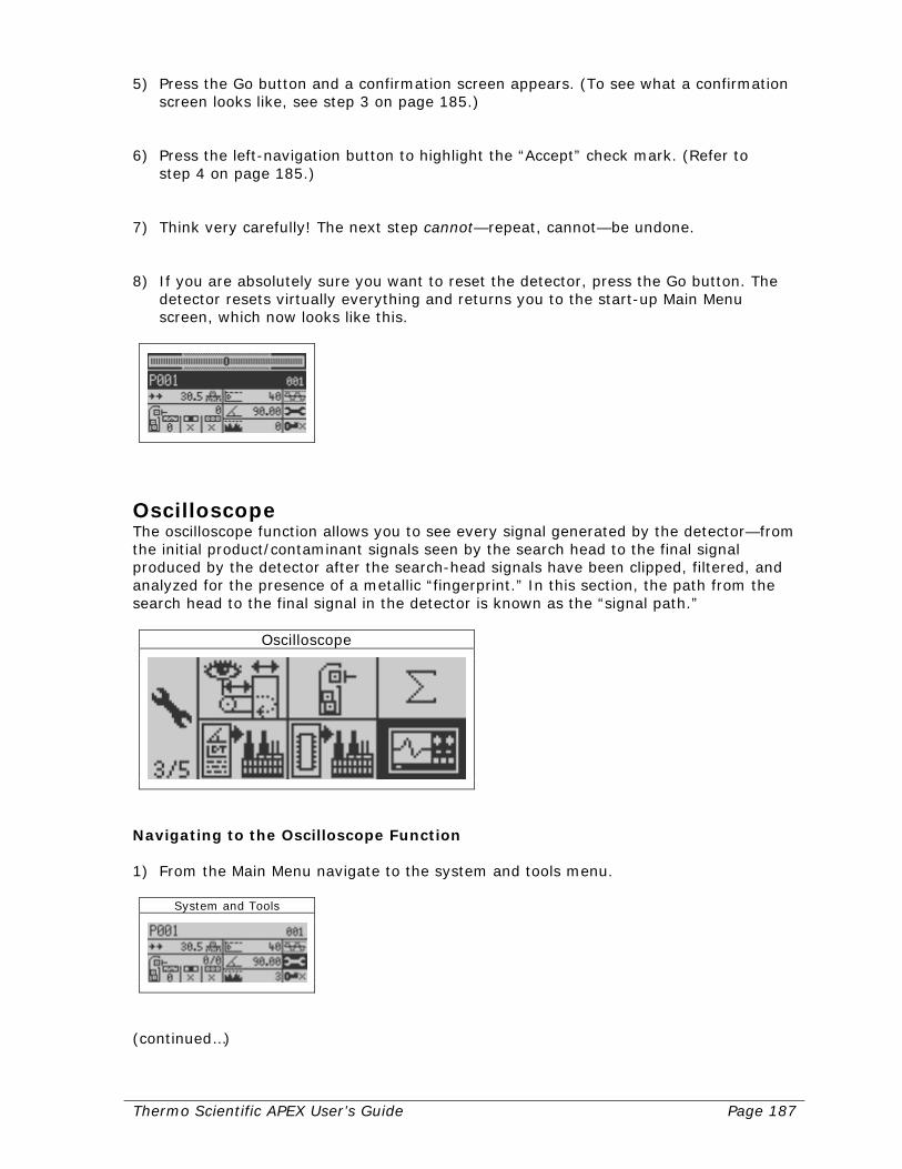
Thermo Scientific APEX User’s Guide Page 187
5) Press the Go button and a confirmation screen appears. (To see what a confirmation screen looks like, see step 3 on page 185.)
6) Press the left-navigation button to highlight the “Accept” check mark. (Refer to
step 4 on page 185.) 7) Think very carefully! The next step cannot—repeat, cannot—be undone. 8) If you are absolutely sure you want to reset the detector, press the Go button. The
detector resets virtually everything and returns you to the start-up Main Menu screen, which now looks like this.
Oscilloscope The oscilloscope function allows you to see every signal generated by the detector—from the initial product/contaminant signals seen by the search head to the final signal produced by the detector after the search-head signals have been clipped, filtered, and analyzed for the presence of a metallic “fingerprint.” In this section, the path from the search head to the final signal in the detector is known as the “signal path.”
Oscilloscope
Navigating to the Oscilloscope Function 1) From the Main Menu navigate to the system and tools menu.
System and Tools
(continued…)

Page 188 Thermo Scientific APEX User’s Guide
2) Press the Go button and navigate to page 3 of the system and tools menu.
System and Tools Page 3
3) Navigate to the oscilloscope function.
Oscilloscope
4) Press the Go button and the start-up oscilloscope screen appears.
Understanding the Signal Path When products or contaminants pass through the search head they generate a pair of signals (known as the X-input signal and the R-input signal). These two signals are then passed through a series of filters, where the signals are clipped, filtered, and analyzed, as shown in the signal path diagram at the end of this section. You can use the oscilloscope function to view the X and R signals (or the combined signal) at any point along the signal path. For example, in the start-up oscilloscope screen above, notice that there are two (analog) signal channels, Channel 1 and Channel 2. (Note, however, that the oscilloscope function also has two digital channels available for use.) Currently, neither analog signal channel has been assigned but, in the example below, you will learn how to assign the X-input signal to Channel 1 and the R-input signal to Channel 2.

Thermo Scientific APEX User’s Guide Page 189
Accessing the Scope-Configuration Menu The scope-configuration menu allows you to control how the oscilloscope functions and how it displays the signals you are interested in. To access the scope-configuration menu, do the following. 1) Make sure the scope-configuration function is highlighted in the start-up oscilloscope
screen.
2) Press the Go button and page 1 of the scope-configuration menu appears.
Scope Configuration 1/2
3) Press the down-navigation button repeated until page 2 of the scope-configuration
menu appears, as shown below.
Scope Configuration 2/2
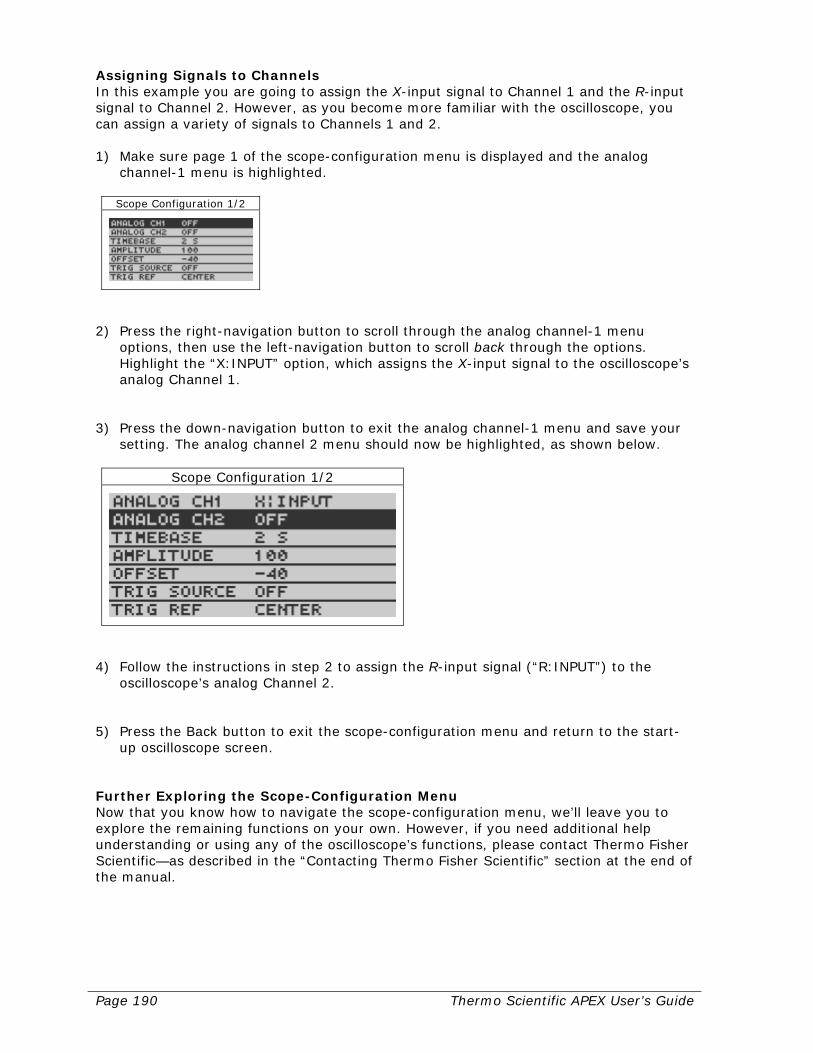
Page 190 Thermo Scientific APEX User’s Guide
Assigning Signals to Channels In this example you are going to assign the X-input signal to Channel 1 and the R-input signal to Channel 2. However, as you become more familiar with the oscilloscope, you can assign a variety of signals to Channels 1 and 2. 1) Make sure page 1 of the scope-configuration menu is displayed and the analog
channel-1 menu is highlighted.
Scope Configuration 1/2
2) Press the right-navigation button to scroll through the analog channel-1 menu
options, then use the left-navigation button to scroll back through the options. Highlight the “X:INPUT” option, which assigns the X-input signal to the oscilloscope’s analog Channel 1.
3) Press the down-navigation button to exit the analog channel-1 menu and save your
setting. The analog channel 2 menu should now be highlighted, as shown below.
Scope Configuration 1/2
4) Follow the instructions in step 2 to assign the R-input signal (“R:INPUT”) to the
oscilloscope’s analog Channel 2. 5) Press the Back button to exit the scope-configuration menu and return to the start-
up oscilloscope screen. Further Exploring the Scope-Configuration Menu Now that you know how to navigate the scope-configuration menu, we’ll leave you to explore the remaining functions on your own. However, if you need additional help understanding or using any of the oscilloscope’s functions, please contact Thermo Fisher Scientific—as described in the “Contacting Thermo Fisher Scientific” section at the end of the manual.
Thermo Scientific APEX User’s Guide Page 191
Here are a few tips on using the scope-configuration functions.
• If you cannot see a signal trace on the oscilloscope screen, go to the amplitude menu (on page 1 of the scope-configuration menu) and enter a higher or lower value to bring the signal within range.
• If the signal trace is either very compressed or very spread out along the
horizontal (time) axis, go to the time-base menu (on page 1 of the scope-configuration menu) and enter a higher or lower value to get the signal “spread” you want.
• If you cannot get the Channel 1 and Channel 2 signals to display together along
the oscilloscope screen’s horizontal center-line, go to the offset function (on page 1 of the scope-configuration menu) and enter a higher or lower value to display the signals to your satisfaction.
Using the Oscilloscope’s Trigger Functions There are three settings for the oscilloscope’s trigger function, as follows. (These functions are accessed from the lower-right corner of the start-up oscilloscope screen.)
• No Trigger This function is abbreviated in the start-up oscilloscope screen as “TRIG: FREE” and tells the oscilloscope to continuously process signal at the rate specified in the time-base menu. Thus, when using this function, the screen scrolls continuously.
• Wait-for-Detection Trigger This function is abbreviated in the start-up oscilloscope screen as “TRIG: WAIT DETECTION” and tells the oscilloscope to wait until a signal is detected, and then display it at the rate specified in the time-base menu. Thus, when using this function, the screen scrolls continuously.
• Hold-After-Detection Trigger This function is abbreviated in the start-up oscilloscope screen as “TRIG: HOLD DETECTION” and tells the oscilloscope to wait until a signal is detected, and then freeze the display, so the signal does not scroll off the screen. Thus, when using this function, the screen is static, making captured signals easy to see and study.
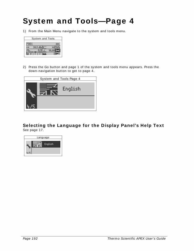
Page 192 Thermo Scientific APEX User’s Guide
System and Tools—Page 4 1) From the Main Menu navigate to the system and tools menu.
System and Tools
2) Press the Go button and page 1 of the system and tools menu appears. Press the
down-navigation button to get to page 4.
System and Tools Page 4
Selecting the Language for the Display Panel’s Help Text See page 17.
Language

Thermo Scientific APEX User’s Guide Page 193
System and Tools—Page 5 1) From the Main Menu navigate to the system and tools menu.
System and Tools
2) Press the Go button and page 1 of the system and tools menu appears. Press the
down-navigation button to get to page 5.
System and Tools Page 4
Displaying Your Software Version This screen displays the current version of the software you are using.
Software Version
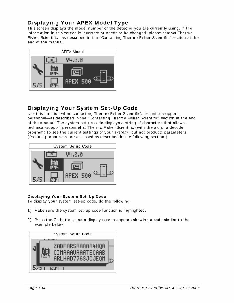
Page 194 Thermo Scientific APEX User’s Guide
Displaying Your APEX Model Type This screen displays the model number of the detector you are currently using. If the information in this screen is incorrect or needs to be changed, please contact Thermo Fisher Scientific—as described in the “Contacting Thermo Fisher Scientific” section at the end of the manual.
APEX Model
Displaying Your System Set-Up Code Use this function when contacting Thermo Fisher Scientific’s technical-support personnel—as described in the “Contacting Thermo Fisher Scientific” section at the end of the manual. The system set-up code displays a string of characters that allows technical-support personnel at Thermo Fisher Scientific (with the aid of a decoder program) to see the current settings of your system (but not product) parameters. (Product parameters are accessed as described in the following section.)
System Setup Code
Displaying Your System Set-Up Code To display your system set-up code, do the following. 1) Make sure the system set-up code function is highlighted. 2) Press the Go button, and a display screen appears showing a code similar to the
example below.
System Setup Code
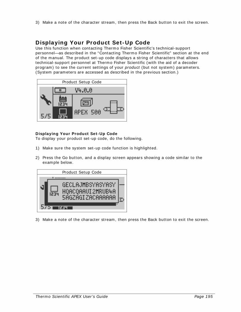
Thermo Scientific APEX User’s Guide Page 195
3) Make a note of the character stream, then press the Back button to exit the screen.
Displaying Your Product Set-Up Code Use this function when contacting Thermo Fisher Scientific’s technical-support personnel—as described in the “Contacting Thermo Fisher Scientific” section at the end of the manual. The product set-up code displays a string of characters that allows technical-support personnel at Thermo Fisher Scientific (with the aid of a decoder program) to see the current settings of your product (but not system) parameters. (System parameters are accessed as described in the previous section.)
Product Setup Code
Displaying Your Product Set-Up Code To display your product set-up code, do the following. 1) Make sure the system set-up code function is highlighted. 2) Press the Go button, and a display screen appears showing a code similar to the
example below.
Product Setup Code
3) Make a note of the character stream, then press the Back button to exit the screen.

Page 196 Thermo Scientific APEX User’s Guide
Quality Test (System and Tools—Page 1) The detector’s Quality Test function allows you to conduct manual tests of the detector’s ability to detect contaminants—in contrast to the detector’s AuditCheck function, which does much the same thing, only automatically and with a significantly greater degree of accuracy. Either function, however, allows you to verify—as part of your overall quality-assurance program—that the detector is working properly during long production runs lasting several hours, several days, a week, and so on.
Quality Test
Navigating to the Quality Test Function 1) From the Main Menu navigate to the system and tools menu.
System and Tools
2) Press the Go button and page 1 of the system and tools menu appears.
System and Tools Page 1
3) Navigate to the Quality Test function and make sure it is highlighted.
Quality Test

Thermo Scientific APEX User’s Guide Page 197
Overview of How the Quality Test Function Works The most commonly used types of test to verify the detector’s response are as follows.
• Three-Metal Test This test uses three different types of metal placed in the center of three separate packets of product. Clearly, which metals you use depends on what contaminants you are interested in. In a typical work environment, this test is conducted using application-specific (conveyor, gravity-feed, or pharmaceutical) ferrous, non-ferrous, or stainless-steel balls. This is the most frequently used of the three types of tests.
• Positional Test This test uses a single contaminant of uniform size (for example the application-specific ferrous test ball) placed in three different positions—usually in the leading, middle, and trailing edge of three separate packets of product.
• Size Test This test uses a single type of metal (for example, ferrous balls), but uses three different sizes ranging through small, medium, and large. Clearly, how small, medium, and large are defined depends on your particular work environment and the size-range of the contaminants you are interested in. In a typical application, the test balls are placed in the center of three separate packets of product.
Managing the QA Test During long production runs, it is a good idea to test the detector’s performance every two hours or thereabouts, and the Quality Test function allows you to manage this process. Here, in outline, is what the Quality Test function does.
• Alerts your shift supervisor—for example by flashing a light—that two hours (or other time interval) has elapsed, and the detector needs to be tested.
• Gives your shift supervisor a 10-minute time window (or other time interval) in
which to start testing. • Shuts down the conveyor automatically, sounds a siren, or takes other action you
specify, if your shift supervisor does not start testing within 10 minutes of the “start testing” signal being activated.
• Monitors peak signal and phase angle during the testing process, and provides a
warning, alarm, or fault if the peak-signal or phase-angle values are not within the limits you specify.
• Assign the reject device (Reject 1 or Reject 2) used to remove contaminated test
products from the conveyor during the QA test. The default setting is to use the Reject-1 device.

Page 198 Thermo Scientific APEX User’s Guide
Learning the QA Test In our example, during the testing phase, the shift supervisor uses three different test samples of a contaminated test product (in our example, rectangular packets that mimic the shape and size of salted butter), as follows.
• Sample A A ferrous contaminant (test ball) in the leading edge of the packet.
• Sample B
A ferrous contaminant (test ball) in the middle of the packet. • Sample C
A ferrous contaminant (test ball) in the trailing edge of the packet. Each sample is passed through the search head three times, for two reasons. First, this allows the detector to average the three peak-signal and phase-angle values, increasing accuracy and precision; and second, if the APEX detects contaminants three times in a row, you can be confident it is working properly.
Testing the Detector Using QA Test Samples 1) Make sure no real product is on the conveyor. If it is not running already, start the
conveyor. Make sure the Quality Test function is highlighted.
Quality Test
2) Press the Go button and page 1 of the quality-assurance-test (QAT) menu appears.
QA Test – Calibrate test samples
This screen shows icons representing the three test samples (Sample A, Sample B, and Sample C) that you will use during the testing process. (continued…)

Thermo Scientific APEX User’s Guide Page 199
3) Press the right-navigation button to highlight Sample A function (also called the “Pack A” function).
Peak & Phase Angle – Pack A
4) Press the Go button and a monitor screen with a flashing-hand/sample-A icon
appears.
Peak & Phase Angle – Pack A
5) Place sample A on the conveyor, allow it to pass through the search head, and
manually catch it on the other side, or allow it to be rejected by your reject-1 device (the default reject device for the Quality Test function).
Pass QA Test pack A to setup
Note: As you pass the contaminated test sample through the search head, the monitor screen will update and show you the number of passes made (in this example = 1). In addition, the average peak-signal value is also updated (in this example = 1150) as well as the average phase-angle value (in this example = 65.00). (continued…)

Page 200 Thermo Scientific APEX User’s Guide
6) Repeat step 5 two more times. Press the Go button, and the Sample-A screen reappears showing the average peak-signal and phase-angle values of the three passes you made.
QA Test – Calibrate test samples
7) Press the Go button to exit the learn function. 8) Repeat steps 3–6 for contaminated test samples B and C.
Setting the Time Interval Between QA Tests This function allows you to set the time interval between QA tests (in minutes). 1) Make sure page 1 of the quality-test menu is highlighted.
QA Test – calibrate…
Note: The detector’s display panel will show actual values, not zeros. 2) Press the down-navigation button and page 2 of the quality-test menu appears.
QA Test – Timers and Reject
(continued…)
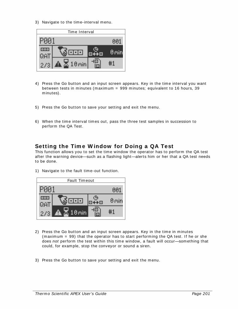
Thermo Scientific APEX User’s Guide Page 201
3) Navigate to the time-interval menu.
Time Interval
4) Press the Go button and an input screen appears. Key in the time interval you want
between tests in minutes (maximum = 999 minutes; equivalent to 16 hours, 39 minutes).
5) Press the Go button to save your setting and exit the menu. 6) When the time interval times out, pass the three test samples in succession to
perform the QA Test.
Setting the Time Window for Doing a QA Test This function allows you to set the time window the operator has to perform the QA test after the warning device—such as a flashing light—alerts him or her that a QA test needs to be done. 1) Navigate to the fault time-out function.
Fault Timeout
2) Press the Go button and an input screen appears. Key in the time in minutes
(maximum = 99) that the operator has to start performing the QA test. If he or she does not perform the test within this time window, a fault will occur—something that could, for example, stop the conveyor or sound a siren.
3) Press the Go button to save your setting and exit the menu.

Page 202 Thermo Scientific APEX User’s Guide
Setting the Reject Device Used for the QA Test This function sets the reject device used during the QA test. The default setting is to assign Reject 1 to the Quality Test function. 1) Navigate to the reject device menu and make sure it is highlighted.
Reject Device
Note: The X indicates that, currently, no reject device is assigned to the Quality Test function. 2) Press the Go button repeatedly to scroll through the reject-device options, which are
as follows. Icon Meaning
No reject device is assigned
Assign reject-device number 1 (Reject 1)
Assign reject-device number 2 (Reject 2)
Note: For your reject device to work, it must be connected to the detector’s wiring board and be assigned to a specific output (Output 1–6). For more details, see pages 290 and 232. 3) When the option you want is shown in the screen, press the Back button to save
your selection and exit the menu. (We have chosen to use our reject-1 device for our quality testing.)
Reject Device
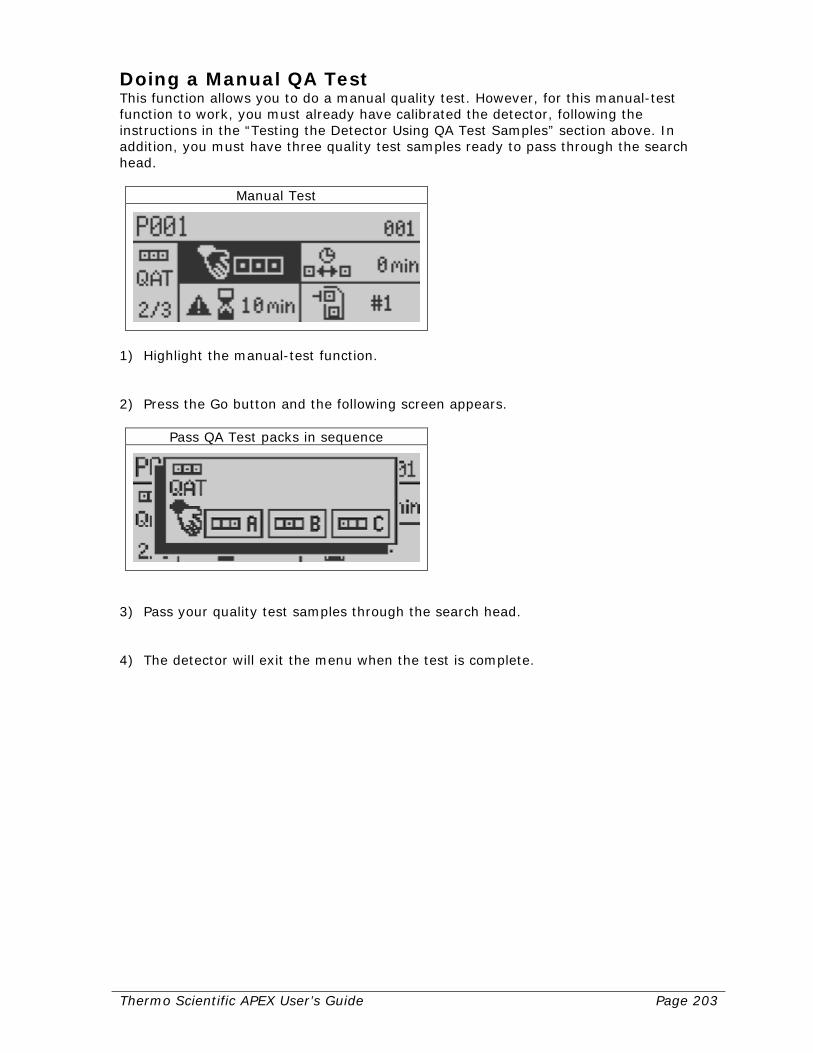
Thermo Scientific APEX User’s Guide Page 203
Doing a Manual QA Test This function allows you to do a manual quality test. However, for this manual-test function to work, you must already have calibrated the detector, following the instructions in the “Testing the Detector Using QA Test Samples” section above. In addition, you must have three quality test samples ready to pass through the search head.
Manual Test
1) Highlight the manual-test function. 2) Press the Go button and the following screen appears.
Pass QA Test packs in sequence
3) Pass your quality test samples through the search head. 4) The detector will exit the menu when the test is complete.
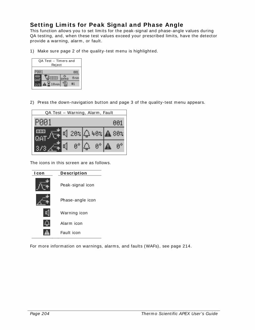
Page 204 Thermo Scientific APEX User’s Guide
Setting Limits for Peak Signal and Phase Angle This function allows you to set limits for the peak-signal and phase-angle values during QA testing, and, when these test values exceed your prescribed limits, have the detector provide a warning, alarm, or fault. 1) Make sure page 2 of the quality-test menu is highlighted.
QA Test – Timers and Reject
2) Press the down-navigation button and page 3 of the quality-test menu appears.
QA Test – Warning, Alarm, Fault
The icons in this screen are as follows.
Icon Description
Peak-signal icon
Phase-angle icon
Warning icon
Alarm icon
Fault icon
For more information on warnings, alarms, and faults (WAFs), see page 214.

Thermo Scientific APEX User’s Guide Page 205
Keying In Limits for Peak-Signal and Phase-Angle Values This menu allows you to key in limits for the peak-signal and phase-angle values obtained when running the QA test. Limits are set as percent change above (+) or below (–) the previous average test value. The function allows you to have the detector give you a warning, alarm, or fault when these limits are exceeded by the current test values. Thus, you should set a small limit (for example, a 20% change) for a warning, a medium-sized limit (for example, a 40% change) for an alarm, and a large limit (for example an 80% change) for a fault to occur. Example In the example below, we are going to change the peak-signal limit for a warning from the default of 20% to 10%. 1) Navigate to the peak-signal warning-tolerance function.
Peak Warning Tolerance
2) Press the Go button, and an input screen appears—showing the warning icon and the
current setting of 20%.
Peak Warning Tolerance
3) Key in a new percent value (“10”) and press the Go button to save your setting and
exit the input screen. 4) Follow the basic outline in steps 1–3 above to change all other values in this screen.
Note that for a warning, alarm, or fault (WAF) to occur, the appropriate external devices must be connected to the detector’s wiring board, and the WAF devices assigned to the appropriate output (Output 1–6). For more information, see pages 232 and 290.

Page 206 Thermo Scientific APEX User’s Guide
AuditCheck (System and Tools—Page 1) The detector’s AuditCheck function allows you to test the detector’s ability to detect contaminants at the same time that product is passing through the search head. The AuditCheck function typically is used only in conveyor applications, and is used as part of your overall quality-assurance program—in particular, during long production runs lasting several hours, several days, a week, and so on. The main advantage of using AuditCheck is that it is able to detect very small changes over time in the sensitivity of the search head and alert you well before contaminated products are likely to pass unnoticed. In comparison to manual testing (which is described in the Quality Test section above), using the AuditCheck function is significantly more accurate and precise, and is virtually foolproof—meaning, if AuditCheck is used regularly, there is little chance of contaminated product passing unnoticed. This section assumes you have already completed the mechanical installation of the AuditCheck components, and have matched the speed of the test shuttle to the speed of the product moving on your conveyor.
AuditCheck
Navigating to the AuditCheck Function 1) From the Main Menu navigate to the system and tools menu.
System and Tools
2) Press the Go button and page 1 of the system and tools menu appears.
System and Tools Page 1
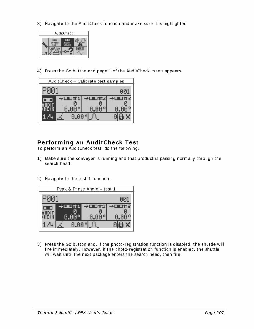
Thermo Scientific APEX User’s Guide Page 207
3) Navigate to the AuditCheck function and make sure it is highlighted.
AuditCheck
4) Press the Go button and page 1 of the AuditCheck menu appears.
AuditCheck – Calibrate test samples
Performing an AuditCheck Test To perform an AuditCheck test, do the following. 1) Make sure the conveyor is running and that product is passing normally through the
search head. 2) Navigate to the test-1 function.
Peak & Phase Angle – test 1
3) Press the Go button and, if the photo-registration function is disabled, the shuttle will
fire immediately. However, if the photo-registration function is enabled, the shuttle will wait until the next package enters the search head, then fire.
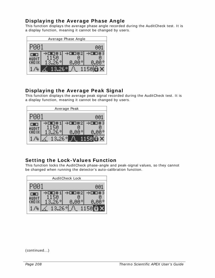
Page 208 Thermo Scientific APEX User’s Guide
Displaying the Average Phase Angle This function displays the average phase angle recorded during the AuditCheck test. It is a display function, meaning it cannot be changed by users.
Average Phase Angle
Displaying the Average Peak Signal This function displays the average peak signal recorded during the AuditCheck test. It is a display function, meaning it cannot be changed by users.
Average Peak
Setting the Lock-Values Function This function locks the AuditCheck phase-angle and peak-signal values, so they cannot be changed when running the detector’s auto-calibration function.
AuditCheck Lock
(continued...)

Thermo Scientific APEX User’s Guide Page 209
Why Locking the AuditCheck Values Is Useful Locking the AuditCheck values for phase angle and peak signal is useful, because it prevents the less-accurate auto-calibration values over-writing the more-accurate AuditCheck values. Auto-calibration values are inherently more variable, because the response of the search head to the passage of a contaminant is dependent on position—for the simple reason that the edge of the head is significantly more responsive than the center. As a result, the AuditCheck values are significantly more accurate than the auto-calibration values for the following reasons. First, the AuditCheck sample always passes through the head in exactly the same position; and second, the AuditCheck sample passes through the edge of the search head, where its response to metallic contaminants is greatest. Locking the AuditCheck Values 1) To lock the AuditCheck values for phase angle and peak signal, highlight the padlock
function. 2) Press the Go button and the X changes to a check mark. 3) Press the Back button to lock these values and exit the function.
Setting Manual-Start, Timing-Limits, and Reject-Device Parameters These functions have already been described in detail for the Quality Test function in the Quality Test section, starting on page 196—so please refer to the appropriate sections in the Quality Test write-up for detailed instructions, as the Timing-Limits, and Reject Device Parameters are very similar for AuditCheck and the Quality Test function.
AuditCheck – Timers and Reject
(continued…)

Page 210 Thermo Scientific APEX User’s Guide
To start a manual AuditCheck, do the following. 1) Make sure the manual AuditCheck menu is highlighted, as shown below.
Manual Test
2) Press the Go button to start the AuditCheck.
Setting Limits for Peak Signal and Phase Angle These functions have already been described in detail for the Quality Test function in the Quality Test section, starting on page 196—so please refer to the appropriate sections in the Quality Test write-up for detailed instructions, as the Peak Signal and Phase Angle Parameters are very similar for AuditCheck and the Quality Test function.
AuditCheck – Warning, Alarm, Fault levels
Setting the AuditCheck Overhang Distance This function allows the filter delay to be accurately tracked, when an AuditCheck test is performed. 1) Navigate to page 4 of the AuditCheck menu.
AuditCheck - Setup

Thermo Scientific APEX User’s Guide Page 211
2) Press the right-navigate button to highlight the overhang function.
AuditCheck – overhang distance
3) Press the Go button and an input screen appears.
AuditCheck – overhang distance
4) Key in your overhang distance in meters or inches (if you set inches as your
preferred units of measure). 5) Press the Go button to save your setting and exit the function.
Setting the AuditCheck Pulse Length The AuditCheck pulse length is the time it takes your product to travel the length of the AuditCheck tube. The detector automatically calculates a value for pulse length using other parameters that have been set up—such as the model of APEX you are using, the type of application you are running (conveyor, gravity-feed, or pipeline), and the values you have set for other functions. However, if the internally generated pulse—for some reason—does not give the exact result you want, you can manually enter a value. How the Detector Calculates Pulse Length When the value for AuditCheck pulse length is set to zero, the detector automatically calculates the value using the following formula.
Pulse Length (ms) = (60 * Search-Head Width) + (2 * Overhang Distance)
Product Speed
Where: Search-Head Width is in mm, Overhang Distance is in mm, and Product Speed is in m/min.
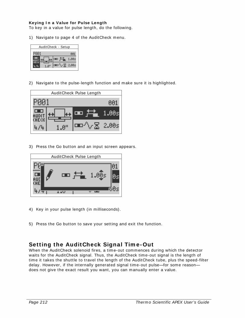
Page 212 Thermo Scientific APEX User’s Guide
Keying In a Value for Pulse Length To key in a value for pulse length, do the following. 1) Navigate to page 4 of the AuditCheck menu.
AuditCheck - Setup
2) Navigate to the pulse-length function and make sure it is highlighted.
AuditCheck Pulse Length
3) Press the Go button and an input screen appears.
AuditCheck Pulse Length
4) Key in your pulse length (in milliseconds). 5) Press the Go button to save your setting and exit the function.
Setting the AuditCheck Signal Time-Out When the AuditCheck solenoid fires, a time-out commences during which the detector waits for the AuditCheck signal. Thus, the AuditCheck time-out signal is the length of time it takes the shuttle to travel the length of the AuditCheck tube, plus the speed-filter delay. However, if the internally generated signal time-out pulse—for some reason—does not give the exact result you want, you can manually enter a value.
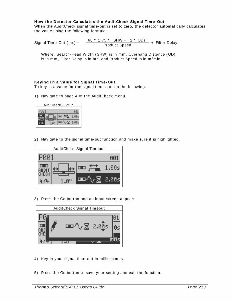
Thermo Scientific APEX User’s Guide Page 213
How the Detector Calculates the AuditCheck Signal Time-Out When the AuditCheck signal time-out is set to zero, the detector automatically calculates the value using the following formula.
Signal Time-Out (ms) = 60 * 1.75 * [SHW + (2 * OD)]
+ Filter Delay Product Speed
Where: Search-Head Width (SHW) is in mm, Overhang Distance (OD) is in mm, Filter Delay is in ms, and Product Speed is in m/min.
Keying In a Value for Signal Time-Out To key in a value for the signal time-out, do the following. 1) Navigate to page 4 of the AuditCheck menu.
AuditCheck - Setup
2) Navigate to the signal time-out function and make sure it is highlighted.
AuditCheck Signal Timeout
3) Press the Go button and an input screen appears.
AuditCheck Signal Timeout
4) Key in your signal time-out in milliseconds. 5) Press the Go button to save your setting and exit the function.

Page 214 Thermo Scientific APEX User’s Guide
Error Messages (WAFs) (System and Tools—Page 1) The detector has three types of error messages: a warning, an alarm, and a fault (WAF). Warnings are the least serious, alarms are more serious, and faults are the most serious type of error message. To be notified when a warning, alarm, or fault occurs, you must hardwire one or more external error-notification devices (lamp, buzzer, siren, and so on) to the detector’s wiring board.
Warnings, Alarms & Faults
Error notification devices are normally connected to detector’s wiring board using the following default outputs. (For more information, see page 290.)
• Warning device—Output 4
• Alarm device—Output 5
• Fault device—Output 6 For more information about assigning the detector’s outputs, see page 232.
Defining Warnings, Alarms, and Faults (WAFs) 1) From the Main Menu, navigate to the system and tools menu.
System and Tools
2) Press the Go button and page 1 of the systems and tools menu appears.
System and Tools Page 1

Thermo Scientific APEX User’s Guide Page 215
3) Navigate to the WAF menu.
Warnings, Alarms & Faults
The icons in this screen are as follows.
Icon Description
Warning
Alarm
Fault
WAFs Are Not Mutually Exclusive The WAF menu contains many functions that can trigger a warning, alarm, or fault—but the categories are not mutually exclusive. This means that for each function shown in the four pages of this menu, the detector can provide any of the following.
• A warning only. • An alarm only. • A fault only. • A warning and an alarm. • A warning and a fault. • A fault and an alarm. • A warning and an alarm and a fault. • None of the above. (No icon is shown next to the function in the menu screen.)
Setting a WAF for a Particular Function In this example, you are going to tell the detector to give you an alarm, when the reject bin is full. (Currently the detector gives you a fault.) We are assuming you have already hardwired a small red lamp (or other error-notification device of your choice) to the default alarm output—Output 5—on the detector’s output-wiring board. 1) Make sure the WAF menu is highlighted.
Warnings, Alarms & Faults

Page 216 Thermo Scientific APEX User’s Guide
2) Press the Go button and page 1 of the WAF menu appears.
Warnings, Alarms & Faults
3) Navigate to the bin-full event menu.
Bin Full event
4) The bin-full error message currently triggers a fault notification. To change the bin-
full error message to an alarm, press the Go button repeatedly to scroll through the error-message options (described above). When you reach the single alarm icon (no other icons are present in the menu), press the Back button to save your setting and exit the menu.
5) Now, in our example, when the reject bin is full, the detector lights the small red
lamp you connected to Output 5. This alarm notifies you the reject bin is full.
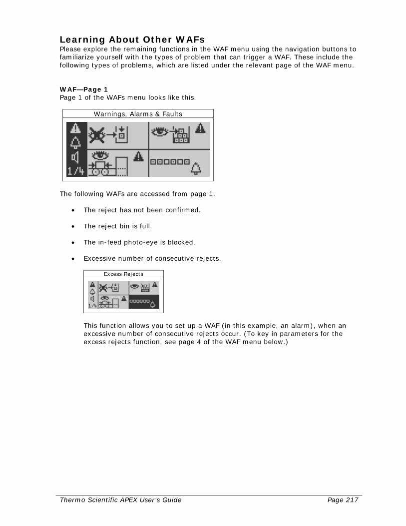
Thermo Scientific APEX User’s Guide Page 217
Learning About Other WAFs Please explore the remaining functions in the WAF menu using the navigation buttons to familiarize yourself with the types of problem that can trigger a WAF. These include the following types of problems, which are listed under the relevant page of the WAF menu. WAF—Page 1 Page 1 of the WAFs menu looks like this.
Warnings, Alarms & Faults
The following WAFs are accessed from page 1.
• The reject has not been confirmed.
• The reject bin is full.
• The in-feed photo-eye is blocked.
• Excessive number of consecutive rejects.
Excess Rejects
This function allows you to set up a WAF (in this example, an alarm), when an excessive number of consecutive rejects occur. (To key in parameters for the excess rejects function, see page 4 of the WAF menu below.)
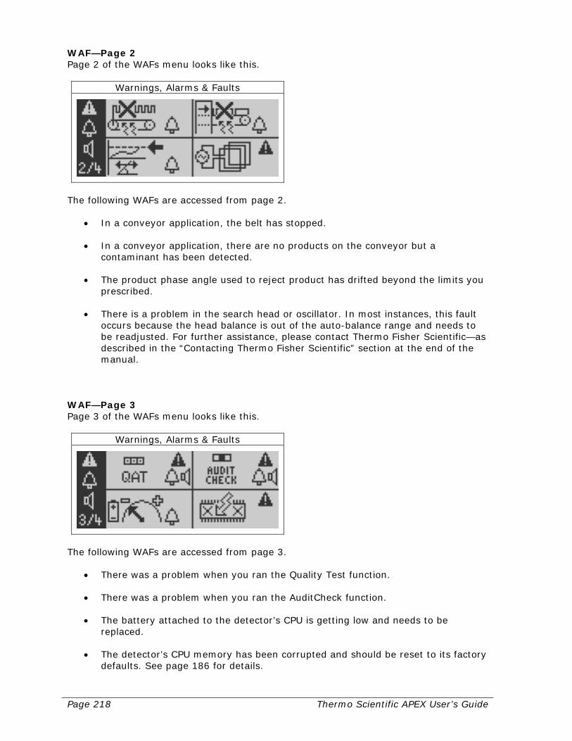
Page 218 Thermo Scientific APEX User’s Guide
WAF—Page 2 Page 2 of the WAFs menu looks like this.
Warnings, Alarms & Faults
The following WAFs are accessed from page 2.
• In a conveyor application, the belt has stopped.
• In a conveyor application, there are no products on the conveyor but a contaminant has been detected.
• The product phase angle used to reject product has drifted beyond the limits you prescribed.
• There is a problem in the search head or oscillator. In most instances, this fault occurs because the head balance is out of the auto-balance range and needs to be readjusted. For further assistance, please contact Thermo Fisher Scientific—as described in the “Contacting Thermo Fisher Scientific” section at the end of the manual.
WAF—Page 3 Page 3 of the WAFs menu looks like this.
Warnings, Alarms & Faults
The following WAFs are accessed from page 3.
• There was a problem when you ran the Quality Test function.
• There was a problem when you ran the AuditCheck function.
• The battery attached to the detector’s CPU is getting low and needs to be replaced.
• The detector’s CPU memory has been corrupted and should be reset to its factory defaults. See page 186 for details.

Thermo Scientific APEX User’s Guide Page 219
WAF—Page 4 Page 4 of the WAFs menu looks like this.
Warnings, Alarms & Faults
The following WAFs are accessed from page 4.
• Excessive number of consecutive rejects in a conveyor application.
Warnings, Alarms, & Faults
Using this menu, you can key in values to warn you when a specified number of rejects occurs in a specified number of units of product passing through the search head. Navigate to the relevant number in this menu, press the Go button, and an input screen appears. Key in your new setting and press the Back button to save your setting and exit.
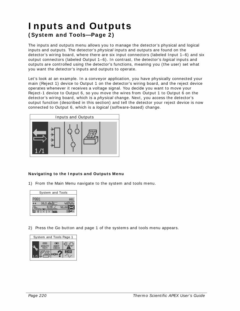
Page 220 Thermo Scientific APEX User’s Guide
Inputs and Outputs (System and Tools—Page 2) The inputs and outputs menu allows you to manage the detector’s physical and logical inputs and outputs. The detector’s physical inputs and outputs are found on the detector’s wiring board, where there are six input connectors (labeled Input 1–6) and six output connectors (labeled Output 1–6). In contrast, the detector’s logical inputs and outputs are controlled using the detector’s functions, meaning you (the user) set what you want the detector’s inputs and outputs to operate. Let’s look at an example. In a conveyor application, you have physically connected your main (Reject 1) device to Output 1 on the detector’s wiring board, and the reject device operates whenever it receives a voltage signal. You decide you want to move your Reject-1 device to Output 6, so you move the wires from Output 1 to Output 6 on the detector’s wiring board, which is a physical change. Next, you access the detector’s output function (described in this section) and tell the detector your reject device is now connected to Output 6, which is a logical (software-based) change.
Inputs and Outputs
Navigating to the Inputs and Outputs Menu 1) From the Main Menu navigate to the system and tools menu.
System and Tools
2) Press the Go button and page 1 of the systems and tools menu appears.
System and Tools Page 1
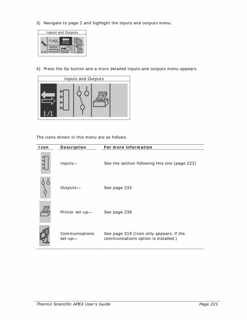
Thermo Scientific APEX User’s Guide Page 221
3) Navigate to page 2 and highlight the inputs and outputs menu.
Inputs and Outputs
4) Press the Go button and a more detailed inputs and outputs menu appears.
Inputs and Outputs
The icons shown in this menu are as follows. Icon Description For more information
Inputs— See the section following this one (page 222)
Outputs— See page 232
Printer set-up— See page 238
Communications set-up—
See page 319 (Icon only appears, if the communications option is installed.)
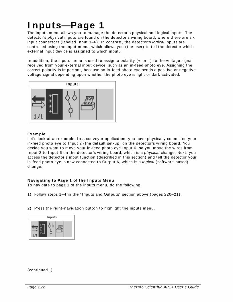
Page 222 Thermo Scientific APEX User’s Guide
Inputs—Page 1 The inputs menu allows you to manage the detector’s physical and logical inputs. The detector’s physical inputs are found on the detector’s wiring board, where there are six input connectors (labeled Input 1–6). In contrast, the detector’s logical inputs are controlled using the input menu, which allows you (the user) to tell the detector which external input device is assigned to which input. In addition, the inputs menu is used to assign a polarity (+ or –) to the voltage signal received from your external input device, such as an in-feed photo eye. Assigning the correct polarity is important, because an in-feed photo eye sends a positive or negative voltage signal depending upon whether the photo eye is light or dark activated.
Inputs
Example Let’s look at an example. In a conveyor application, you have physically connected your in-feed photo eye to Input 2 (the default set-up) on the detector’s wiring board. You decide you want to move your in-feed photo eye Input 6, so you move the wires from Input 2 to Input 6 on the detector’s wiring board, which is a physical change. Next, you access the detector’s input function (described in this section) and tell the detector your in-feed photo eye is now connected to Output 6, which is a logical (software-based) change. Navigating to Page 1 of the Inputs Menu To navigate to page 1 of the inputs menu, do the following. 1) Follow steps 1–4 in the “Inputs and Outputs” section above (pages 220–21). 2) Press the right-navigation button to highlight the inputs menu.
Inputs
(continued…)

Thermo Scientific APEX User’s Guide Page 223
3) Press the Go button and page 1 of the input set-up menu appears.
Input Setup
Viewing the Speed-Encoder Input This function is used only in conveyor applications and is a display function, meaning you cannot make changes to the input assigned to the speed encoder. The speed encoder must be wired to Input 1 and is permanently assigned to Input 1 with a positive (+) polarity.
Encoder Input (FIXED)
Assigning the Input for the In-Feed Photo Eye This function is used only in conveyor applications and assigns the input for the in-feed photo eye.
Infeed Photo Eye Input
1) Press the Go button and an input screen appears. 2) Make the appropriate assignments for input (Input 1–6) and polarity (+ or –). 3) Press the Go button to save your settings. 4) Press the Back button to exit the menu.
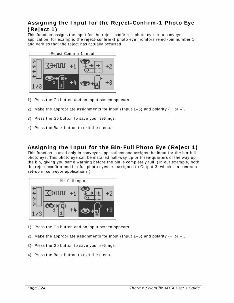
Page 224 Thermo Scientific APEX User’s Guide
Assigning the Input for the Reject-Confirm-1 Photo Eye (Reject 1) This function assigns the input for the reject-confirm-1 photo eye. In a conveyor application, for example, the reject-confirm-1 photo eye monitors reject-bin number 1, and verifies that the reject has actually occurred.
Reject Confirm 1 Input
1) Press the Go button and an input screen appears. 2) Make the appropriate assignments for input (Input 1–6) and polarity (+ or –). 3) Press the Go button to save your settings. 4) Press the Back button to exit the menu.
Assigning the Input for the Bin-Full Photo Eye (Reject 1) This function is used only in conveyor applications and assigns the input for the bin-full photo eye. This photo eye can be installed half-way up or three-quarters of the way up the bin, giving you some warning before the bin is completely full. (In our example, both the reject-confirm and bin-full photo eyes are assigned to Output 3, which is a common set-up in conveyor applications.)
Bin Full Input
1) Press the Go button and an input screen appears. 2) Make the appropriate assignments for input (Input 1–6) and polarity (+ or –). 3) Press the Go button to save your settings. 4) Press the Back button to exit the menu.
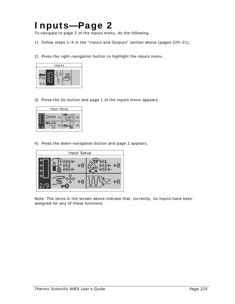
Thermo Scientific APEX User’s Guide Page 225
Inputs—Page 2 To navigate to page 2 of the inputs menu, do the following. 1) Follow steps 1–4 in the “Inputs and Outputs” section above (pages 220–21). 2) Press the right-navigation button to highlight the inputs menu.
Inputs
3) Press the Go button and page 1 of the inputs menu appears.
Input Setup
4) Press the down-navigation button and page 2 appears.
Input Setup
Note: The zeros in the screen above indicate that, currently, no inputs have been assigned for any of these functions.
Page 226 Thermo Scientific APEX User’s Guide
Using an External Device to Switch Products This function allows an external device—such as a programmable logic controller (PLC)—to tell the detector to change the running product to one of the first three products. Example You are a supervisor at a dairy. In the morning you use your APEX and a conveyor application to analyze milk, but at noon every day, you need to start analyzing salted butter. You have installed a PLC that changes the configuration of your conveyor every day at noon, and need to alert the APEX when this change occurs. This is done by having the PLC send signals to the detector’s Inputs (Inputs assigned to Product Select One and Product Select Two). When input signal voltage changes due to the PLC, the APEX can immediately stop analyzing milk (Product 1), and load all the product parameters you have set for salted butter (Product 2). The detector is now ready to start analyzing salted butter (Product 2). 1) Make sure appropriate menu is highlighted. 2) Press the Go button and an input screen appears. 3) Make the appropriate assignments for input (Input 1–6) and polarity (+ or –). 4) Press the Go button to save your settings. 5) Press the Back button to exit the menu. The APEX can automatically switch to any of the first three products, as shown by the parameters in the table below. New running product
Product select 1 input
Product select 2 input
No change False False
Product 1 True False
Product 2 False True
Product 3 True True
Note: A product-select input that is not assigned (input = 0), will always be treated as false.
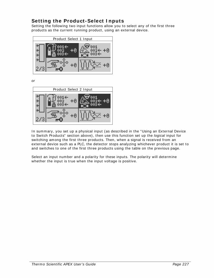
Thermo Scientific APEX User’s Guide Page 227
Setting the Product-Select Inputs Setting the following two input functions allow you to select any of the first three products as the current running product, using an external device.
Product Select 1 Input
or
Product Select 2 Input
In summary, you set up a physical input (as described in the “Using an External Device to Switch Products” section above), then use this function set up the logical input for switching among the first three products. Then, when a signal is received from an external device such as a PLC, the detector stops analyzing whichever product it is set to and switches to one of the first three products using the table on the previous page. Select an input number and a polarity for these inputs. The polarity will determine whether the input is true when the input voltage is positive.
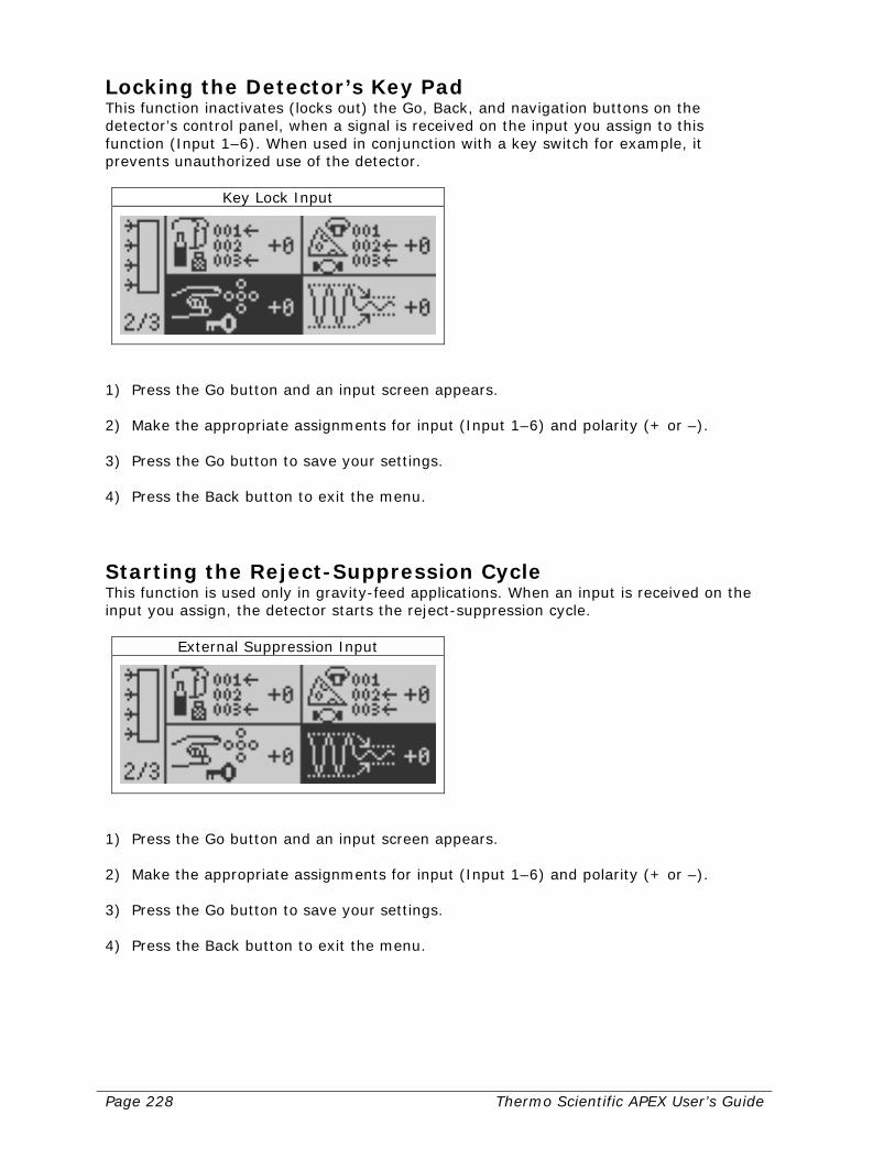
Page 228 Thermo Scientific APEX User’s Guide
Locking the Detector’s Key Pad This function inactivates (locks out) the Go, Back, and navigation buttons on the detector’s control panel, when a signal is received on the input you assign to this function (Input 1–6). When used in conjunction with a key switch for example, it prevents unauthorized use of the detector.
Key Lock Input
1) Press the Go button and an input screen appears. 2) Make the appropriate assignments for input (Input 1–6) and polarity (+ or –). 3) Press the Go button to save your settings. 4) Press the Back button to exit the menu.
Starting the Reject-Suppression Cycle This function is used only in gravity-feed applications. When an input is received on the input you assign, the detector starts the reject-suppression cycle.
External Suppression Input
1) Press the Go button and an input screen appears. 2) Make the appropriate assignments for input (Input 1–6) and polarity (+ or –). 3) Press the Go button to save your settings. 4) Press the Back button to exit the menu.

Thermo Scientific APEX User’s Guide Page 229
Inputs—Page 3 To navigate to page 3 of the inputs menu, do the following. 1) Follow steps 1–4 in the “Inputs and Outputs” section above (pages 220–21). 2) Press the right-navigation button to highlight the inputs menu.
Inputs
3) Press the Go button and page 1 of the inputs menu appears.
Input Setup
4) Press the down-navigation button twice and page 3 appears.
Input Setup

Page 230 Thermo Scientific APEX User’s Guide
Assigning the Input for Verification of a Reject Using Photo-Eye 2 This function is used most-often in gravity-feed and pipeline applications. The function assigns the input (Input 1–6) for photo-eye number 2, and is used to verify that the reject process has ceased. For example, in a pipeline application where a contaminated raw material (such as canola oil) is diverted to a waste tank, this function is used to confirm that normal flow has resumed to your manufacturing process.
Reject Confirm 2 Input
1) Press the Go button and an input screen appears. 2) Make the appropriate assignments for input (Input 1–6) and polarity (+ or –). 3) Press the Go button to save your settings. 4) Press the Back button to exit the menu.
Assigning the Reject-2 Confirm Input This function assigns the input for the “reject-2 confirm” photo eye. In a conveyor application, for example, the “reject-2 confirm” photo eye monitors reject-bin number 2, and verifies that the reject has actually occurred. It is often used in conveyor applications fitted with two reject devices, one that handles contaminated products and the other that handles AuditCheck and Quality Test rejects.
Reject 2 Confirm Input
1) Press the Go button and an input screen appears. 2) Make the appropriate assignments for input (Input 1–6) and polarity (+ or –). 3) Press the Go button to save your settings. 4) Press the Back button to exit the menu.
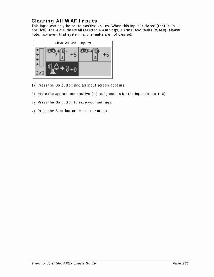
Thermo Scientific APEX User’s Guide Page 231
Clearing All WAF Inputs This input can only be set to positive values. When this input is closed (that is, is positive), the APEX clears all resettable warnings, alarms, and faults (WAFs). Please note, however, that system failure faults are not cleared.
Clear All WAF Inputs
1) Press the Go button and an input screen appears. 2) Make the appropriate positive (+) assignments for the input (Input 1–6). 3) Press the Go button to save your settings. 4) Press the Back button to exit the menu.
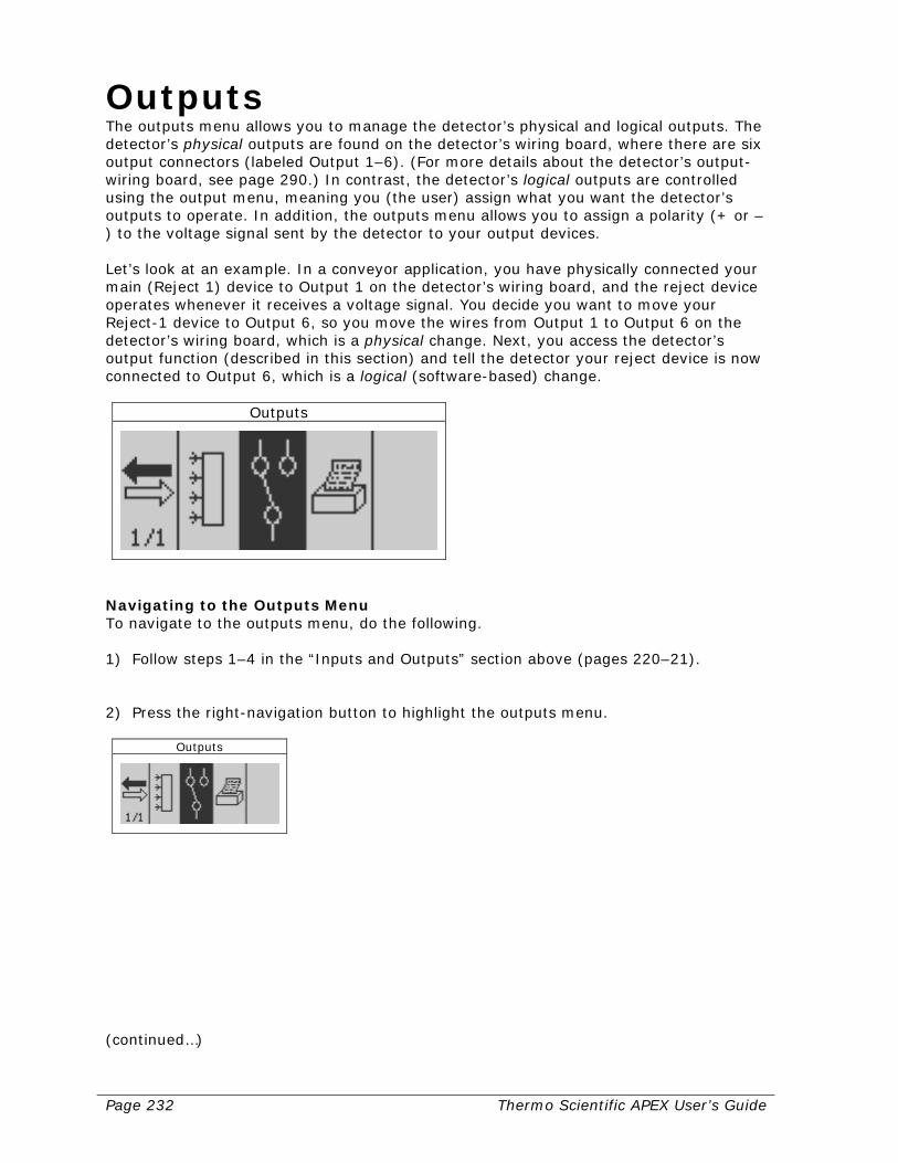
Page 232 Thermo Scientific APEX User’s Guide
Outputs The outputs menu allows you to manage the detector’s physical and logical outputs. The detector’s physical outputs are found on the detector’s wiring board, where there are six output connectors (labeled Output 1–6). (For more details about the detector’s output-wiring board, see page 290.) In contrast, the detector’s logical outputs are controlled using the output menu, meaning you (the user) assign what you want the detector’s outputs to operate. In addition, the outputs menu allows you to assign a polarity (+ or –) to the voltage signal sent by the detector to your output devices. Let’s look at an example. In a conveyor application, you have physically connected your main (Reject 1) device to Output 1 on the detector’s wiring board, and the reject device operates whenever it receives a voltage signal. You decide you want to move your Reject-1 device to Output 6, so you move the wires from Output 1 to Output 6 on the detector’s wiring board, which is a physical change. Next, you access the detector’s output function (described in this section) and tell the detector your reject device is now connected to Output 6, which is a logical (software-based) change.
Outputs
Navigating to the Outputs Menu To navigate to the outputs menu, do the following. 1) Follow steps 1–4 in the “Inputs and Outputs” section above (pages 220–21). 2) Press the right-navigation button to highlight the outputs menu.
Outputs
(continued…)
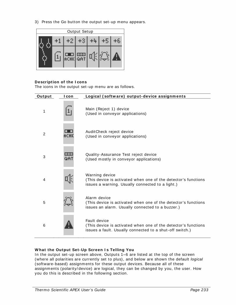
Thermo Scientific APEX User’s Guide Page 233
3) Press the Go button the output set-up menu appears.
Output Setup
Description of the Icons The icons in the output set-up menu are as follows. Output Icon Logical (software) output-device assignments
1
Main (Reject 1) device (Used in conveyor applications)
2
AuditCheck reject device (Used in conveyor applications)
3
Quality-Assurance Test reject device (Used mostly in conveyor applications)
4
Warning device (This device is activated when one of the detector’s functions issues a warning. Usually connected to a light.)
5
Alarm device (This device is activated when one of the detector’s functions issues an alarm. Usually connected to a buzzer.)
6
Fault device (This device is activated when one of the detector’s functions issues a fault. Usually connected to a shut-off switch.)
What the Output Set-Up Screen Is Telling You In the output set-up screen above, Outputs 1–6 are listed at the top of the screen (where all polarities are currently set to plus), and below are shown the default logical (software-based) assignments for these output devices. Because all of these assignments (polarity/device) are logical, they can be changed by you, the user. How you do this is described in the following section.
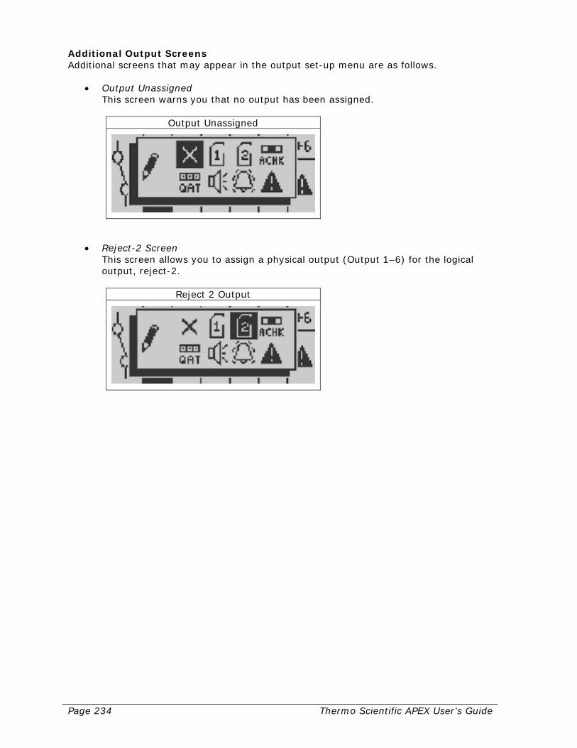
Page 234 Thermo Scientific APEX User’s Guide
Additional Output Screens Additional screens that may appear in the output set-up menu are as follows.
• Output Unassigned This screen warns you that no output has been assigned.
Output Unassigned
• Reject-2 Screen This screen allows you to assign a physical output (Output 1–6) for the logical output, reject-2.
Reject 2 Output
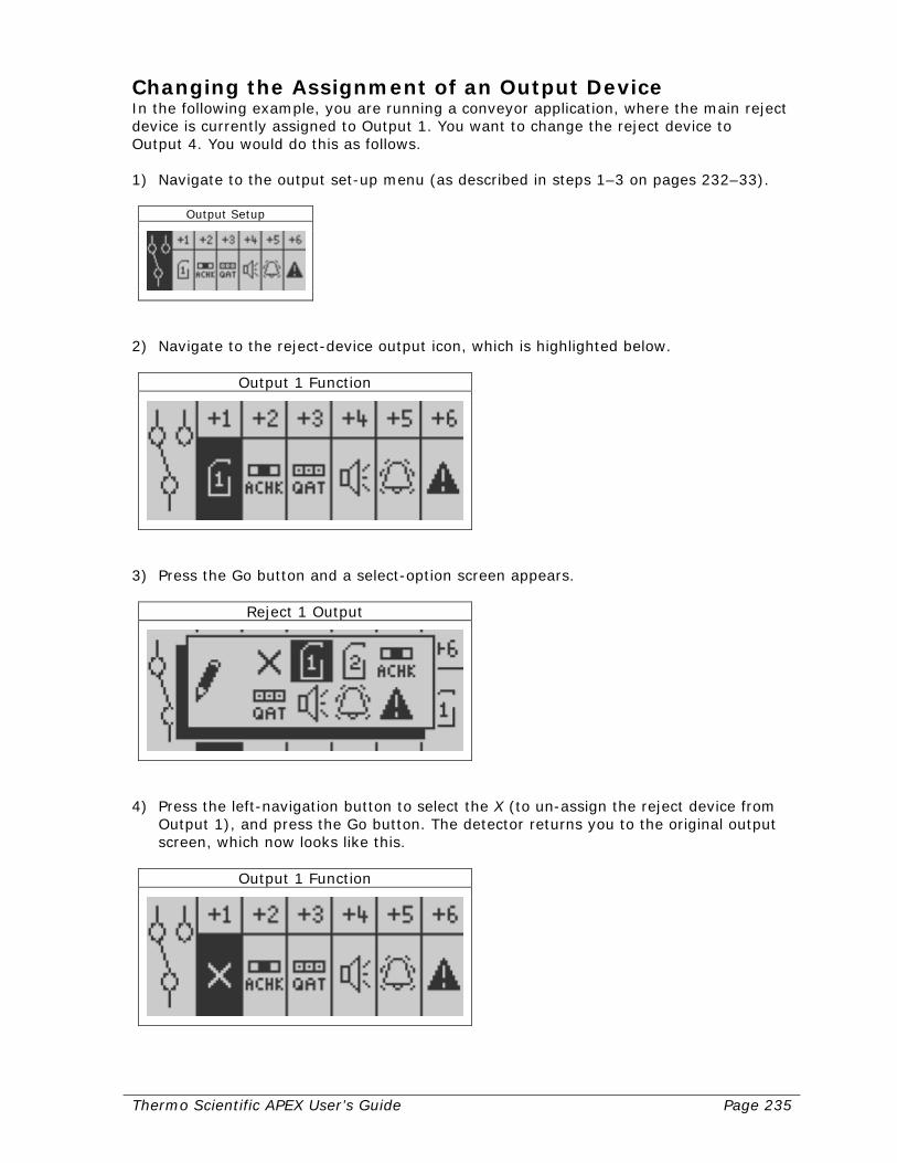
Thermo Scientific APEX User’s Guide Page 235
Changing the Assignment of an Output Device In the following example, you are running a conveyor application, where the main reject device is currently assigned to Output 1. You want to change the reject device to Output 4. You would do this as follows. 1) Navigate to the output set-up menu (as described in steps 1–3 on pages 232–33).
Output Setup
2) Navigate to the reject-device output icon, which is highlighted below.
Output 1 Function
3) Press the Go button and a select-option screen appears.
Reject 1 Output
4) Press the left-navigation button to select the X (to un-assign the reject device from
Output 1), and press the Go button. The detector returns you to the original output screen, which now looks like this.
Output 1 Function
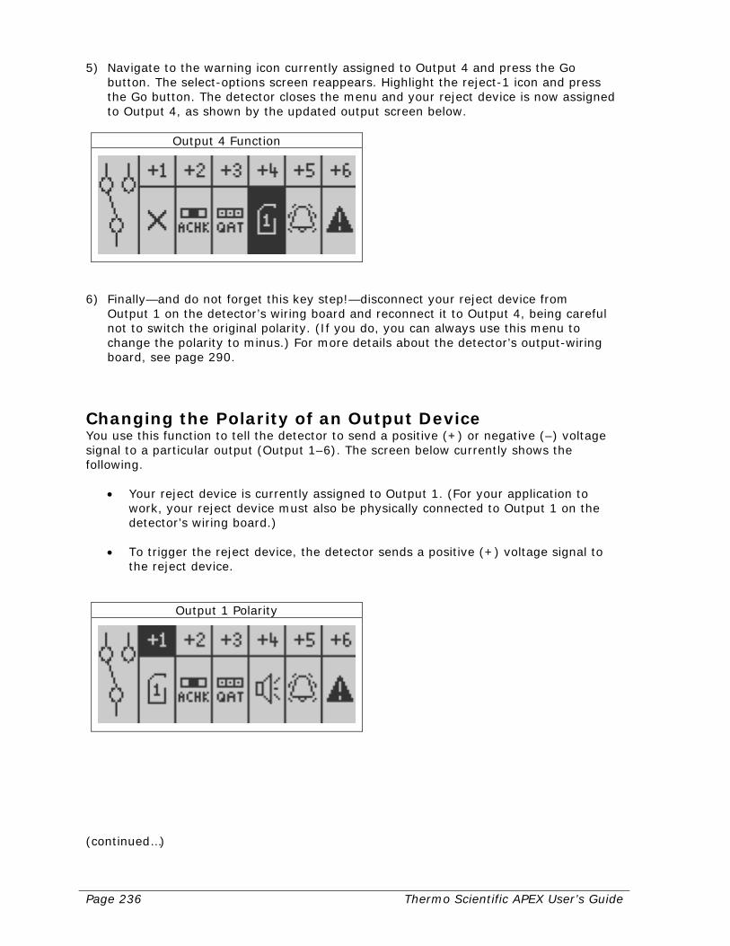
Page 236 Thermo Scientific APEX User’s Guide
5) Navigate to the warning icon currently assigned to Output 4 and press the Go button. The select-options screen reappears. Highlight the reject-1 icon and press the Go button. The detector closes the menu and your reject device is now assigned to Output 4, as shown by the updated output screen below.
Output 4 Function
6) Finally—and do not forget this key step!—disconnect your reject device from
Output 1 on the detector’s wiring board and reconnect it to Output 4, being careful not to switch the original polarity. (If you do, you can always use this menu to change the polarity to minus.) For more details about the detector’s output-wiring board, see page 290.
Changing the Polarity of an Output Device You use this function to tell the detector to send a positive (+) or negative (–) voltage signal to a particular output (Output 1–6). The screen below currently shows the following.
• Your reject device is currently assigned to Output 1. (For your application to work, your reject device must also be physically connected to Output 1 on the detector’s wiring board.)
• To trigger the reject device, the detector sends a positive (+) voltage signal to the reject device.
Output 1 Polarity
(continued…)

Thermo Scientific APEX User’s Guide Page 237
Example of Changing the Polarity for an Output Device To continue our example from the section above, having moved your reject device to Output 4, you now want to change its polarity from positive (+) to negative (–). 1) Navigate to the “+4” icon in the outputs menu.
Output 4 Polarity
2) Press the Go button and the icon changes to “–4,” indicating the polarity of Output 4
in now negative (–).
Output 4 Polarity
3) Press the Back button to save your changes and exit the menu.
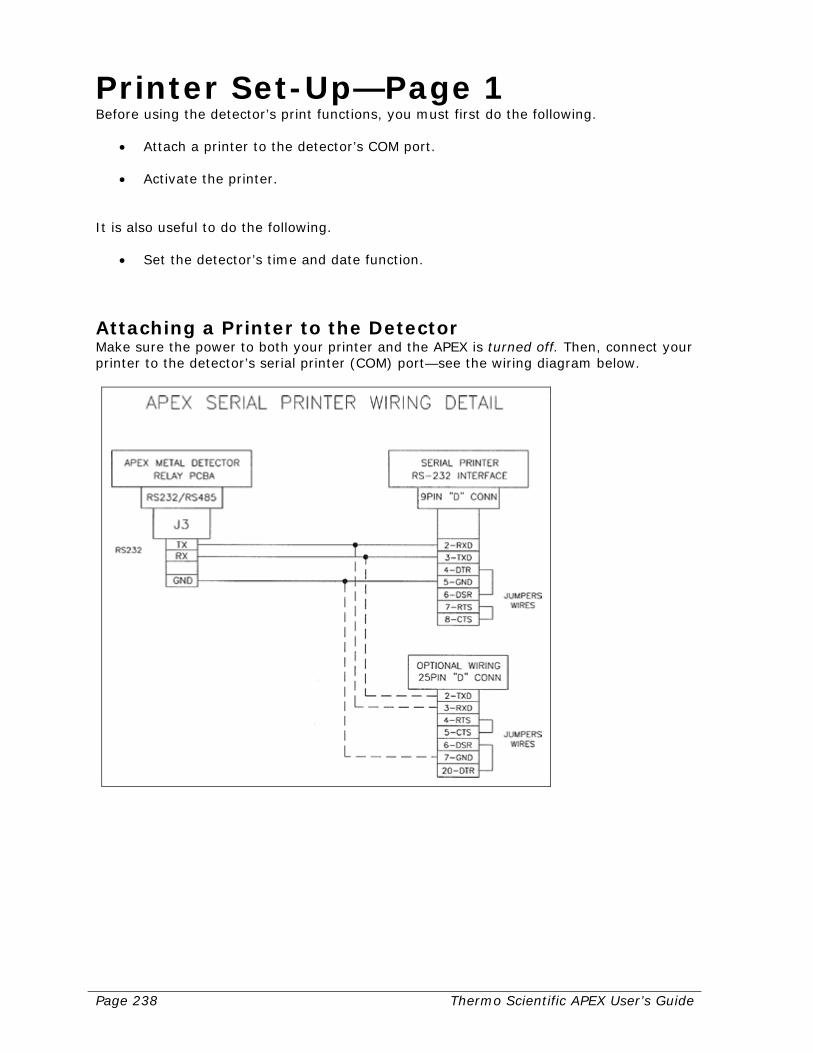
Page 238 Thermo Scientific APEX User’s Guide
Printer Set-Up—Page 1 Before using the detector’s print functions, you must first do the following.
• Attach a printer to the detector’s COM port. • Activate the printer.
It is also useful to do the following.
• Set the detector’s time and date function.
Attaching a Printer to the Detector Make sure the power to both your printer and the APEX is turned off. Then, connect your printer to the detector’s serial printer (COM) port—see the wiring diagram below.
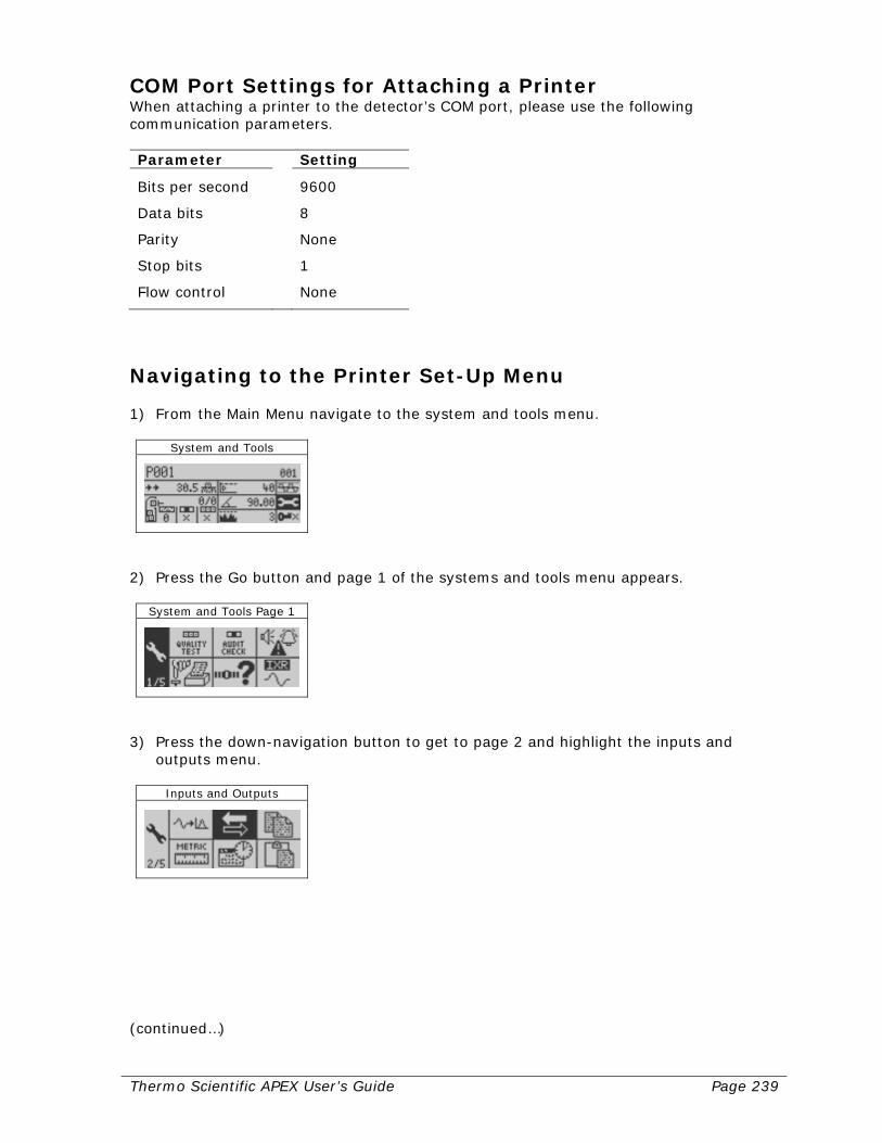
Thermo Scientific APEX User’s Guide Page 239
COM Port Settings for Attaching a Printer When attaching a printer to the detector’s COM port, please use the following communication parameters. Parameter Setting
Bits per second 9600
Data bits 8
Parity None
Stop bits 1
Flow control None
Navigating to the Printer Set-Up Menu 1) From the Main Menu navigate to the system and tools menu.
System and Tools
2) Press the Go button and page 1 of the systems and tools menu appears.
System and Tools Page 1
3) Press the down-navigation button to get to page 2 and highlight the inputs and
outputs menu.
Inputs and Outputs
(continued…)

Page 240 Thermo Scientific APEX User’s Guide
4) Press the Go button and the inputs and outputs menu appears.
Inputs and Outputs
5) Navigate to the printer icon.
Printer Setup
6) Press the Go button and page 1 of the printer set-up menu appears.
Printer Setup Page 1
Setting the Detector’s Time and Date Functions Setting the detector’s time and date functions is useful, for two reasons. First, any reports you print will have a time and date stamp (which helps you keep proper records as part of your quality-assurance program). And second, the detector’s end-of-day print-out function will only work if the time function is set for the detector. For instructions on how to set the detector’s time and date function, see page 176.

Thermo Scientific APEX User’s Guide Page 241
Activating the Printer Once the printer is attached to the detector, before you can print, you must first activate the printer. Note that, once you have activated the printer, whenever you change products or change various functions, a print will occur. 1) Follow steps 1–6 in the section above to reach page 1 of the printer set-up menu.
Printer Setup Page 1
2) Navigate to the activate-printer function.
Activate Printer
Note: The X shows that the printer is currently inactivated. 3) Press the Go button and the X changes to a check mark. The printer is now activated
and ready to print. 4) Press the Back button to exit the menu.
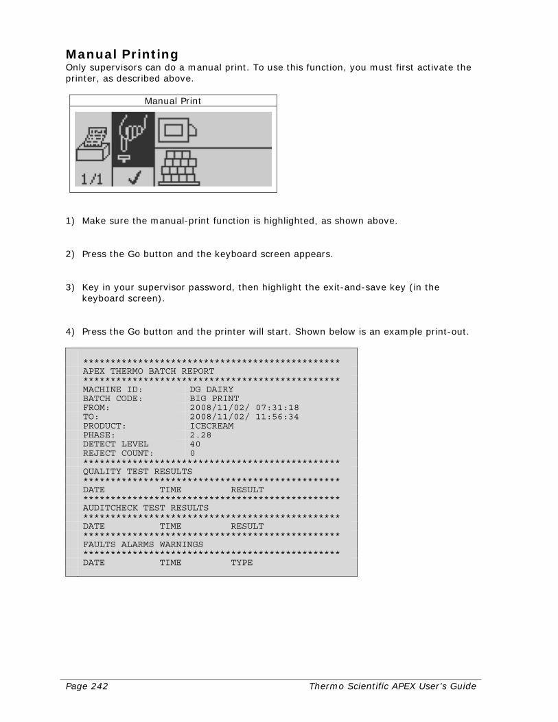
Page 242 Thermo Scientific APEX User’s Guide
Manual Printing Only supervisors can do a manual print. To use this function, you must first activate the printer, as described above.
Manual Print
1) Make sure the manual-print function is highlighted, as shown above. 2) Press the Go button and the keyboard screen appears. 3) Key in your supervisor password, then highlight the exit-and-save key (in the
keyboard screen). 4) Press the Go button and the printer will start. Shown below is an example print-out. *********************************************** APEX THERMO BATCH REPORT *********************************************** MACHINE ID: DG DAIRY BATCH CODE: BIG PRINT FROM: 2008/11/02/ 07:31:18 TO: 2008/11/02/ 11:56:34 PRODUCT: ICECREAM PHASE: 2.28 DETECT LEVEL 40 REJECT COUNT: 0 *********************************************** QUALITY TEST RESULTS *********************************************** DATE TIME RESULT *********************************************** AUDITCHECK TEST RESULTS *********************************************** DATE TIME RESULT *********************************************** FAULTS ALARMS WARNINGS *********************************************** DATE TIME TYPE
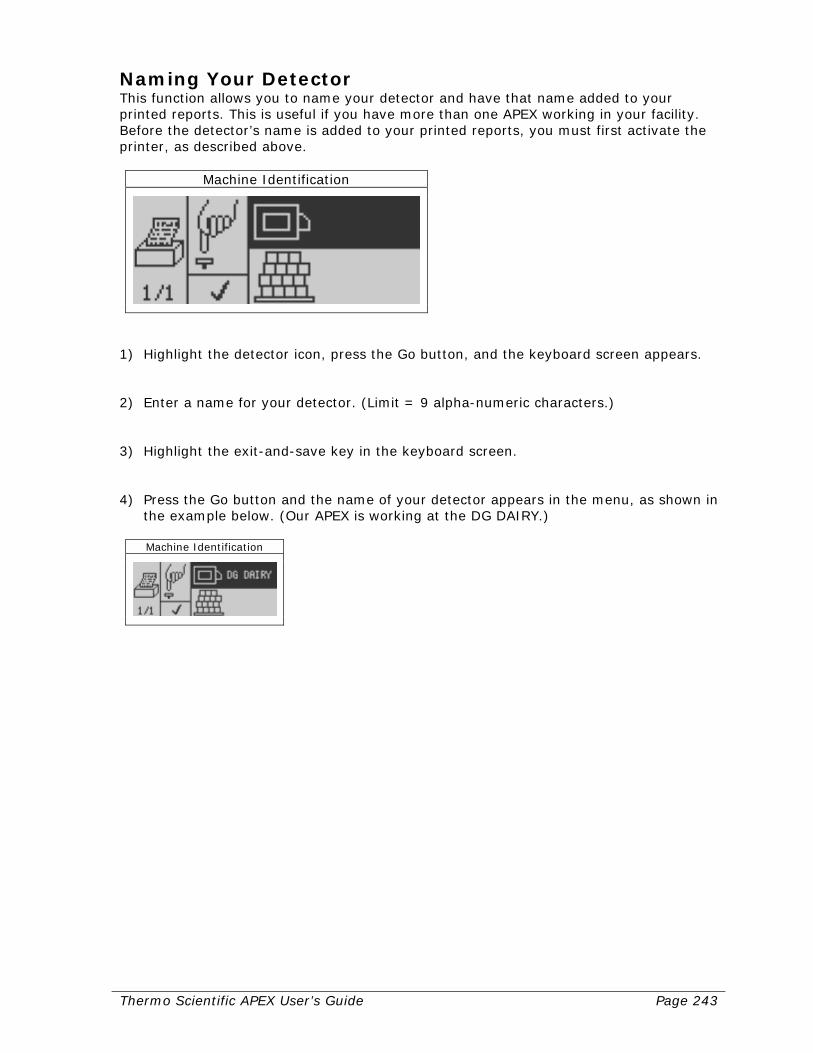
Thermo Scientific APEX User’s Guide Page 243
Naming Your Detector This function allows you to name your detector and have that name added to your printed reports. This is useful if you have more than one APEX working in your facility. Before the detector’s name is added to your printed reports, you must first activate the printer, as described above.
Machine Identification
1) Highlight the detector icon, press the Go button, and the keyboard screen appears. 2) Enter a name for your detector. (Limit = 9 alpha-numeric characters.) 3) Highlight the exit-and-save key in the keyboard screen. 4) Press the Go button and the name of your detector appears in the menu, as shown in
the example below. (Our APEX is working at the DG DAIRY.)
Machine Identification

Page 244 Thermo Scientific APEX User’s Guide
Naming Your Product Batches This function allows you to add the name of the batch of products you are testing to your printed reports. To use this function, you must first activate the printer, as described above.
Batch Code
1) Highlight the batch-code icon, press the Go button, and the keyboard screen
appears. 2) Enter a name for your batch of products. (Limit = 9 alpha-numeric characters.) 3) Highlight the exit-and-save key in the keyboard screen. 4) Press the Go button and your batch code appears in the menu, as shown in the
example below. (We are testing batch 01-123456.)
Batch Code
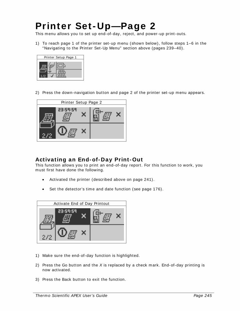
Thermo Scientific APEX User’s Guide Page 245
Printer Set-Up—Page 2 This menu allows you to set up end-of-day, reject, and power-up print-outs. 1) To reach page 1 of the printer set-up menu (shown below), follow steps 1–6 in the
“Navigating to the Printer Set-Up Menu” section above (pages 239–40).
Printer Setup Page 1
2) Press the down-navigation button and page 2 of the printer set-up menu appears.
Printer Setup Page 2
Activating an End-of-Day Print-Out This function allows you to print an end-of-day report. For this function to work, you must first have done the following.
• Activated the printer (described above on page 241). • Set the detector’s time and date function (see page 176).
Activate End of Day Printout
1) Make sure the end-of-day function is highlighted. 2) Press the Go button and the X is replaced by a check mark. End-of-day printing is
now activated. 3) Press the Back button to exit the function.
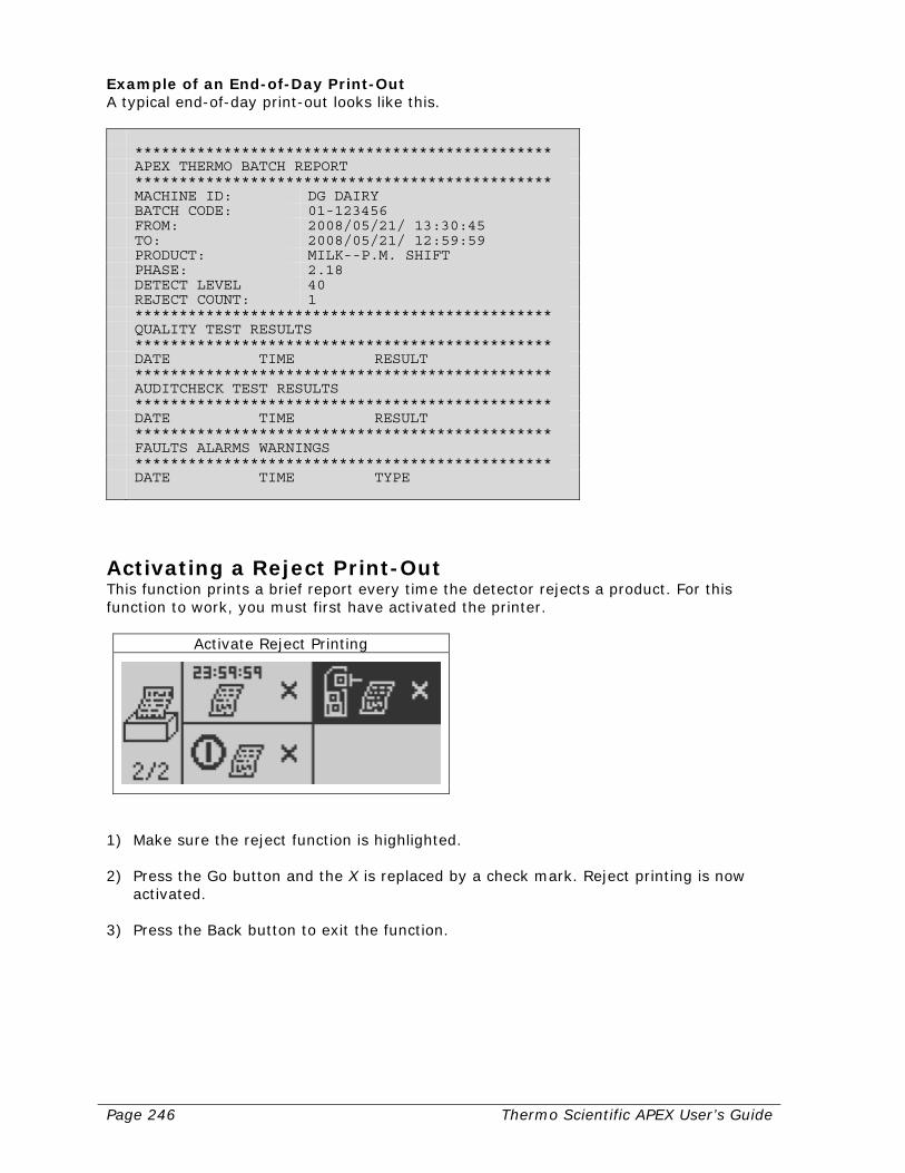
Page 246 Thermo Scientific APEX User’s Guide
Example of an End-of-Day Print-Out A typical end-of-day print-out looks like this. *********************************************** APEX THERMO BATCH REPORT *********************************************** MACHINE ID: DG DAIRY BATCH CODE: 01-123456 FROM: 2008/05/21/ 13:30:45 TO: 2008/05/21/ 12:59:59 PRODUCT: MILK--P.M. SHIFT PHASE: 2.18 DETECT LEVEL 40 REJECT COUNT: 1 *********************************************** QUALITY TEST RESULTS *********************************************** DATE TIME RESULT *********************************************** AUDITCHECK TEST RESULTS *********************************************** DATE TIME RESULT *********************************************** FAULTS ALARMS WARNINGS *********************************************** DATE TIME TYPE
Activating a Reject Print-Out This function prints a brief report every time the detector rejects a product. For this function to work, you must first have activated the printer.
Activate Reject Printing
1) Make sure the reject function is highlighted. 2) Press the Go button and the X is replaced by a check mark. Reject printing is now
activated. 3) Press the Back button to exit the function.

Thermo Scientific APEX User’s Guide Page 247
Example of a Reject Print-Out A typical reject print-out looks like this. REJECT 2008/05/21 15:50:00 4/789
This print-out tells you that, when you printed on May 21, 2008 at exactly 3:50 p.m., four products out of a total of 789 products examined were rejected since the reject totals were reset. Thus, when you activate a reject print-out, the printer simply prints the current total (or totals) displayed in the reject-totals menu in the Main Menu—as shown in the example below.
Product Name
Activating a Print-Out on Power-Up This prints a standard report whenever the detector is powered up. For this function to work, you must first have activated the printer.
Activate Printout on Power-up
1) Make sure the power-up function is highlighted. 2) Press the Go button and the X is replaced by a check mark. Power-up printing is now
activated. 3) Press the Back button to exit the function.
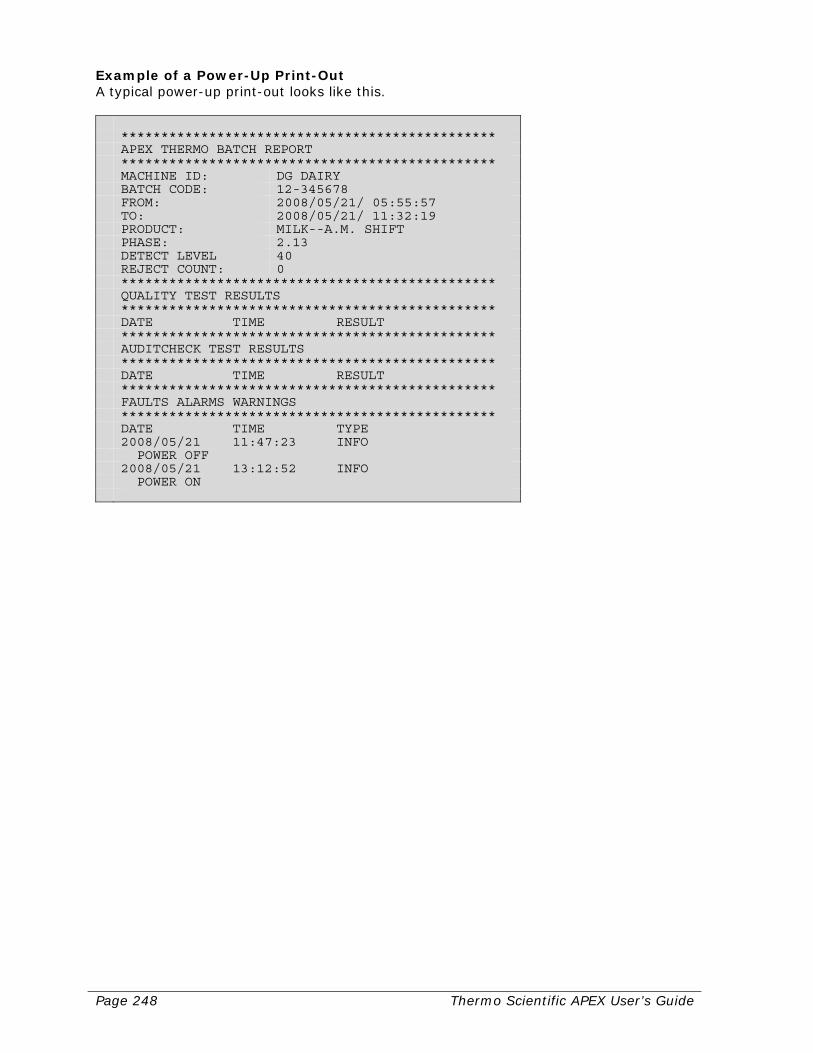
Page 248 Thermo Scientific APEX User’s Guide
Example of a Power-Up Print-Out A typical power-up print-out looks like this. *********************************************** APEX THERMO BATCH REPORT *********************************************** MACHINE ID: DG DAIRY BATCH CODE: 12-345678 FROM: 2008/05/21/ 05:55:57 TO: 2008/05/21/ 11:32:19 PRODUCT: MILK--A.M. SHIFT PHASE: 2.13 DETECT LEVEL 40 REJECT COUNT: 0 *********************************************** QUALITY TEST RESULTS *********************************************** DATE TIME RESULT *********************************************** AUDITCHECK TEST RESULTS *********************************************** DATE TIME RESULT *********************************************** FAULTS ALARMS WARNINGS *********************************************** DATE TIME TYPE 2008/05/21 11:47:23 INFO POWER OFF 2008/05/21 13:12:52 INFO POWER ON

Thermo Scientific APEX User’s Guide Page 249
Security Level If you wish to restrict access to your APEX detector, you (as a supervisor) must assign passwords to operators, engineers, and yourself. The following table shows the access privileges of operators, engineers, and supervisors as well as their default passwords. Use the default passwords, when entering this menu for the first time to set up security levels for yourself and your coworkers. Unlike a personal computer, no names are used—only passwords. Thus, all supervisors, engineers, and operators are recognized only by their passwords.
Acc
ess
L
evel
Use
r N
am
e
Defa
ult
P
ass
wo
rd
Available to this Access Level
Not Available to this Access Level
0 Read/Lock (None) View everything
Clear peak Language
(N/A)
1 Operator 1 OPR1 AutoLearn
Learn detect level Change products
Adjust— Phase angle Detect level
2 Operator 2 OPR2 Manual AuditCheck
Manual QAT Manual print Learn and adjust—
Phase angle Detect level
Learn IXR Edit pack length Learn reject
confirmations Reset reject counts
Pack gap Detect no-pack
distance Machine settings Reject settings I/O settings Phase and IXR
tracking AuditCheck settings QAT settings
3 Engineer ENGI Everything except
password changes Passwords
NVRAM reset 4 Supervisor SUPE Everything Set APEX model
or machine type SF factory menu
5 Factory – Model/machine
SF factory menu Password required for
every change
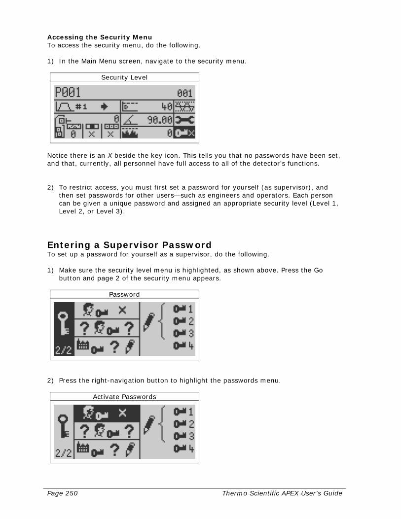
Page 250 Thermo Scientific APEX User’s Guide
Accessing the Security Menu To access the security menu, do the following. 1) In the Main Menu screen, navigate to the security menu.
Security Level
Notice there is an X beside the key icon. This tells you that no passwords have been set, and that, currently, all personnel have full access to all of the detector’s functions. 2) To restrict access, you must first set a password for yourself (as supervisor), and
then set passwords for other users—such as engineers and operators. Each person can be given a unique password and assigned an appropriate security level (Level 1, Level 2, or Level 3).
Entering a Supervisor Password To set up a password for yourself as a supervisor, do the following. 1) Make sure the security level menu is highlighted, as shown above. Press the Go
button and page 2 of the security menu appears.
Password
2) Press the right-navigation button to highlight the passwords menu.
Activate Passwords
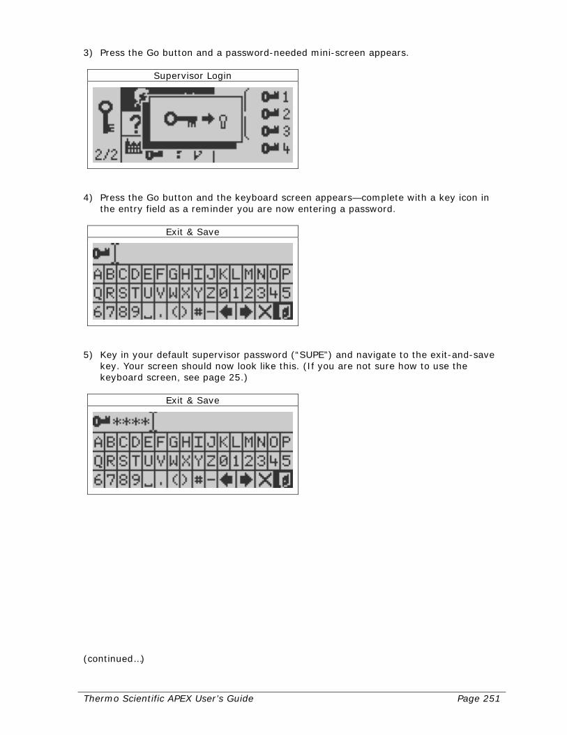
Thermo Scientific APEX User’s Guide Page 251
3) Press the Go button and a password-needed mini-screen appears.
Supervisor Login
4) Press the Go button and the keyboard screen appears—complete with a key icon in
the entry field as a reminder you are now entering a password.
Exit & Save
5) Key in your default supervisor password (“SUPE”) and navigate to the exit-and-save
key. Your screen should now look like this. (If you are not sure how to use the keyboard screen, see page 25.)
Exit & Save
(continued…)
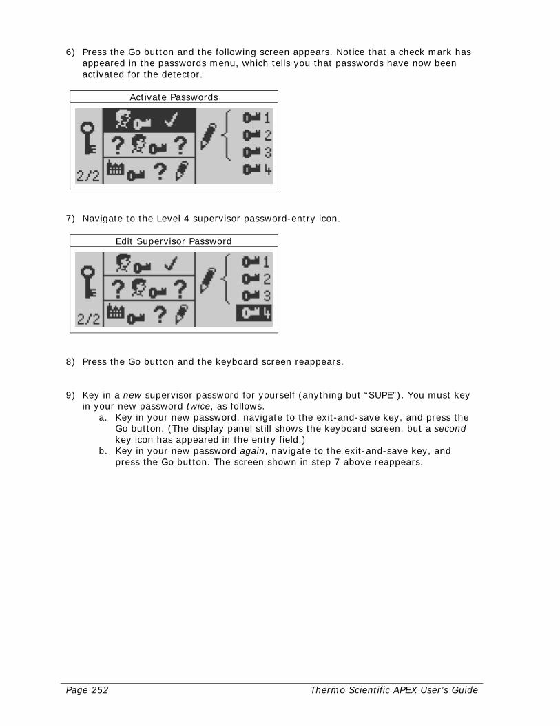
Page 252 Thermo Scientific APEX User’s Guide
6) Press the Go button and the following screen appears. Notice that a check mark has appeared in the passwords menu, which tells you that passwords have now been activated for the detector.
Activate Passwords
7) Navigate to the Level 4 supervisor password-entry icon.
Edit Supervisor Password
8) Press the Go button and the keyboard screen reappears. 9) Key in a new supervisor password for yourself (anything but “SUPE”). You must key
in your new password twice, as follows. a. Key in your new password, navigate to the exit-and-save key, and press the
Go button. (The display panel still shows the keyboard screen, but a second key icon has appeared in the entry field.)
b. Key in your new password again, navigate to the exit-and-save key, and press the Go button. The screen shown in step 7 above reappears.
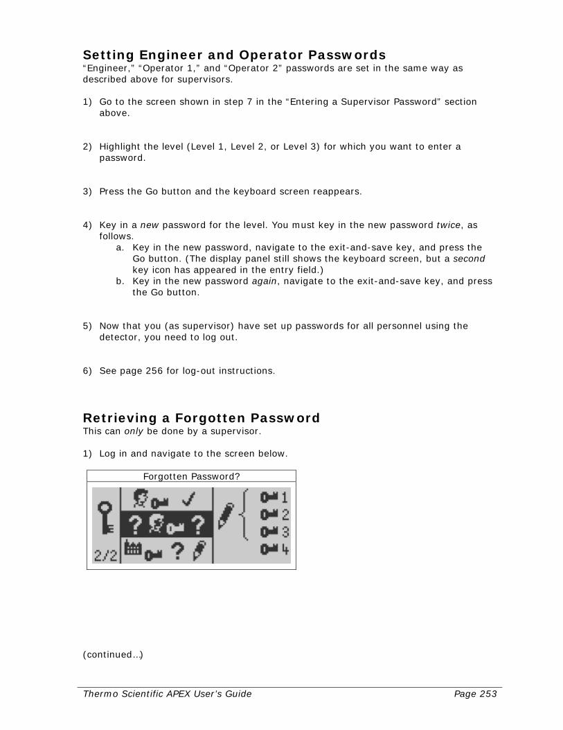
Thermo Scientific APEX User’s Guide Page 253
Setting Engineer and Operator Passwords “Engineer,” “Operator 1,” and “Operator 2” passwords are set in the same way as described above for supervisors. 1) Go to the screen shown in step 7 in the “Entering a Supervisor Password” section
above. 2) Highlight the level (Level 1, Level 2, or Level 3) for which you want to enter a
password. 3) Press the Go button and the keyboard screen reappears. 4) Key in a new password for the level. You must key in the new password twice, as
follows. a. Key in the new password, navigate to the exit-and-save key, and press the
Go button. (The display panel still shows the keyboard screen, but a second key icon has appeared in the entry field.)
b. Key in the new password again, navigate to the exit-and-save key, and press the Go button.
5) Now that you (as supervisor) have set up passwords for all personnel using the
detector, you need to log out. 6) See page 256 for log-out instructions.
Retrieving a Forgotten Password This can only be done by a supervisor. 1) Log in and navigate to the screen below.
Forgotten Password?
(continued…)
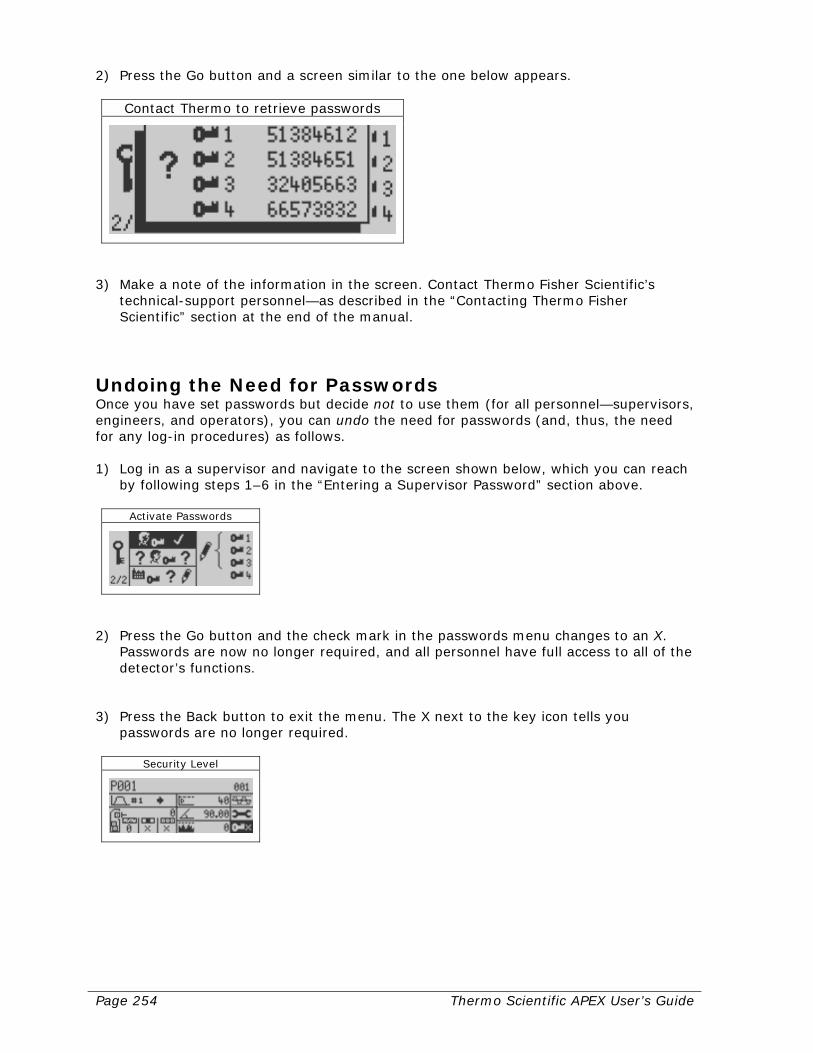
Page 254 Thermo Scientific APEX User’s Guide
2) Press the Go button and a screen similar to the one below appears.
Contact Thermo to retrieve passwords
3) Make a note of the information in the screen. Contact Thermo Fisher Scientific’s
technical-support personnel—as described in the “Contacting Thermo Fisher Scientific” section at the end of the manual.
Undoing the Need for Passwords Once you have set passwords but decide not to use them (for all personnel—supervisors, engineers, and operators), you can undo the need for passwords (and, thus, the need for any log-in procedures) as follows. 1) Log in as a supervisor and navigate to the screen shown below, which you can reach
by following steps 1–6 in the “Entering a Supervisor Password” section above.
Activate Passwords
2) Press the Go button and the check mark in the passwords menu changes to an X.
Passwords are now no longer required, and all personnel have full access to all of the detector’s functions.
3) Press the Back button to exit the menu. The X next to the key icon tells you
passwords are no longer required.
Security Level

Thermo Scientific APEX User’s Guide Page 255
Logging In If passwords have been set for the detector, you must first log in. 1) In the Main Menu screen, navigate to the security menu.
Security Level
Note: The zero next to the key icon tells you that, currently, no one is logged in to the detector. 2) Press the Go button and the log-in screen appears.
Login
3) Press the Go button and the keyboard screen appears—complete with a key icon in
the entry field as a reminder you are now entering a password.
Exit & Save
(continued..)
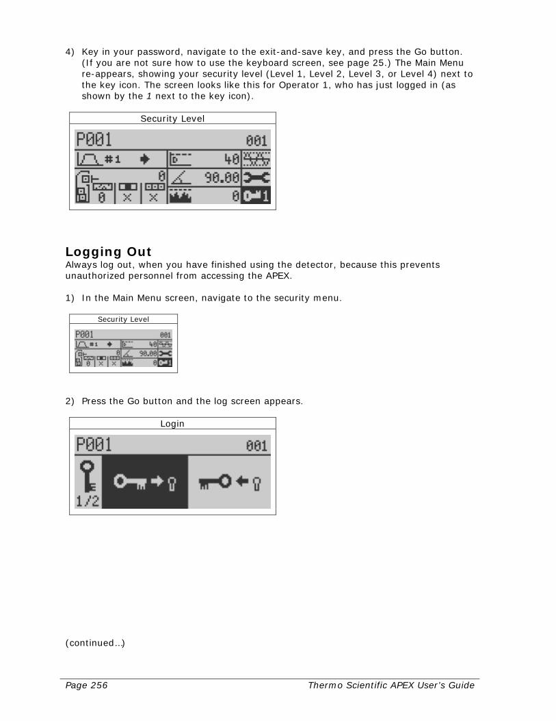
Page 256 Thermo Scientific APEX User’s Guide
4) Key in your password, navigate to the exit-and-save key, and press the Go button. (If you are not sure how to use the keyboard screen, see page 25.) The Main Menu re-appears, showing your security level (Level 1, Level 2, Level 3, or Level 4) next to the key icon. The screen looks like this for Operator 1, who has just logged in (as shown by the 1 next to the key icon).
Security Level
Logging Out Always log out, when you have finished using the detector, because this prevents unauthorized personnel from accessing the APEX. 1) In the Main Menu screen, navigate to the security menu.
Security Level
2) Press the Go button and the log screen appears.
Login
(continued…)
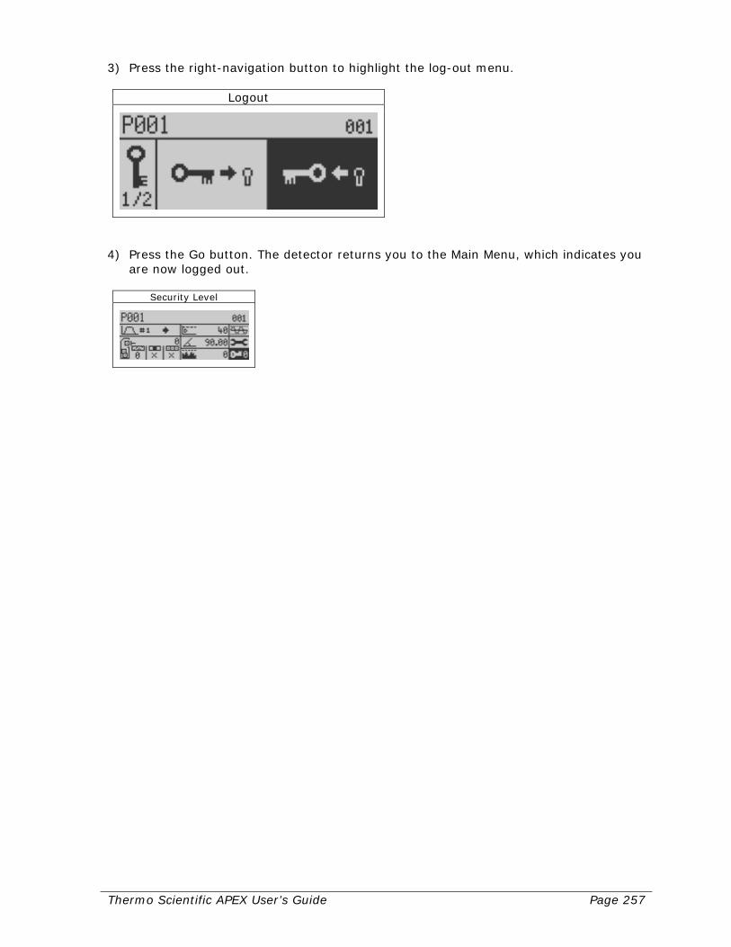
Thermo Scientific APEX User’s Guide Page 257
3) Press the right-navigation button to highlight the log-out menu.
Logout
4) Press the Go button. The detector returns you to the Main Menu, which indicates you
are now logged out.
Security Level

Page 258 Thermo Scientific APEX User’s Guide
Thermo Scientific APEX User’s Guide Page 259
Maintenance and Troubleshooting This section describes how to maintain and test your APEX detector, and provides a troubleshooting guide to help you resolve problems should a fault occur.
Maintenance You should regularly clean the APEX, if you want it to provide long-term, trouble-free operation. Please note that certain cleaning agents could affect the integrity and appearance of the plastics used on the search head. Read the labels on all cleaning agents to make sure they do not adversely affect polycarbonate- and polyester-plastic materials. If you have any questions about cleaning procedures, please contact Thermo Fisher Scientific—as described in the “Contacting Thermo Fisher Scientific” section at the end of the manual. Cleaning Please make sure that your cleaning procedures do not leave residues on the detector’s surfaces, because these might attract dust particles. In addition, please dry all surfaces after cleaning. In addition, please consult the suppliers of your cleaning agents to make sure they are suitable for use on conveyors and ancillary equipment, and use the appropriate dilution levels when cleaning Do not use high-pressure hoses to clean the APEX as these may damage the APEX or cause breaches in the integrity of the unit. In addition, using high-pressure cleaning equipment may compromise safety and lead to problems with contamination. Checking for Corrosion Although the APEX is made from corrosion-resistant materials, corrosion may occur. For example, stainless steel prevents surface corrosion by rapidly producing a strong and inert oxide layer. Damage to this protective oxide layer may result if you rest iron objects on the detector’s surfaces. Please check for signs of corrosion on a regular basis and take preventative measures to stop corrosion occurring. Any sign of corrosion should be investigated. Please report any incidents of corrosion to Thermo Fisher Scientific.

Page 260 Thermo Scientific APEX User’s Guide
Recommended Test Procedures You should thoroughly test the detector and all reject devices when these are first installed, and whenever a major component of the system is changed or altered—for example, when any part is serviced or repaired. In addition, when setting up the test procedures for your particular working environment, please take note of the following considerations and recommendations. Pass Test Samples Through the Center of the Search Head The least sensitive part of the search head is along the centerline of the opening. As a result, it is best run test sample passes through the centerline of the opening. If the test sample is run at the side of the aperture or product tube, this will produce a larger signal than through the centerline. The test procedure should consider this for consistent results. Choose Appropriately-Sized Test Samples Sensitivity capabilities of different detectors used in different applications will vary. Smaller aperture is capable of detecting smaller pieces of metal. Product effect may also alter the detection capability. It is inadvisable to rely on a corporate standard to determine and test the detector’s operation. Ideally, each detector should have its own standards of operation and a corporate outline should be used only as a maximum allowable guide. Sample sizes should be selected so that they are clearly detectable when compared to the signal produced by the product or other interfering signals. If samples are established which are very close to the product signal, frustration on the part of operators can lead to a lack of confidence in the detector’s operation. Use the Normal Product Flow-Rate During Testing The detector should be tested at its normal operating speed. Test samples should be placed on conveyors so that they will pass through the detector at normal speed. On pipelines, test samples should be inserted so that they travel through the search-head at the product’s normal flow. On gravity-feed and tablet/pharmaceutical applications, test samples should be placed so they fall from same point as the product. Ferrous Metals Are Easier to Detect than Stainless Steel The detector is not equally sensitive to all types of metal. Depending on the type of product and application there can be three typical metal groups which will produce three different levels of detection. Ferrous metals are the easiest to detect, and non-magnetic stainless steels are the most difficult to detect.
• Ferrous metals—any iron derivative.
• Non-ferrous metals—any good electricity-conducting metals such as aluminum, copper, brass, and so forth.
• Stainless steel—any of the 300-series stainless steels, which are non-magnetic. These are often the most difficult metals to detect.

Thermo Scientific APEX User’s Guide Page 261
Always Use Spherical Test Samples Your test samples should contain spherical metal contaminants. Any other shape produces a different size signal, depending on its orientation as it passes through the search head. As a result, miscellaneously-shaped test samples can lead to inconsistent results. Test the Entire Reject Process In most applications, when the reject process fails, the reject device is to blame. So, always test the entire reject process to verify your reject device is working properly. In addition, make sure that, if the reject device fails, you can safely recover your test samples. If you have safety concerns about your reject process, please contact Thermo Fisher Scientific—as described in the “Contacting Thermo Fisher Scientific” section at the end of the manual. Keep Things Simple So Testing Is Done Frequently If the test procedures you implement are simple, you and your operators are more likely to do them on a regular basis. As a general rule, the detector should be tested once per shift, or—at a minimum—on a daily basis. Keep Written Records of All Tests You should keep detailed written records, as part of your overall quality-assurance program, of all tests done on the detector. Good records allow you to build up a historical record of the performance of the detector and its associated components over time, and will help you head off current problems and identify problems in the future. Carefully Examine All Rejected Products All rejected products should be carefully examined to determine exactly what type of contamination they contain, and—most important of all—to allow you to identify the exact source of the contamination. Rejected products, for example, should be examined as soon as the shift ends (or, at a minimum, on a daily basis), to ensure that problems upstream of your detector are indentified and corrected in a timely manner. Enable the Detector’s QA Test Function Use the detector’s QA Test function to ensure that its performance will be tested on a regular basis by you or your operators. Enable the Detector’s AuditCheck Function If the optional AuditCheck hardware is installed on your detector, set up the AuditCheck function. When the AuditCheck function is enabled, the detector’s performance is automatically tested at regular intervals—without the need for operator intervention.
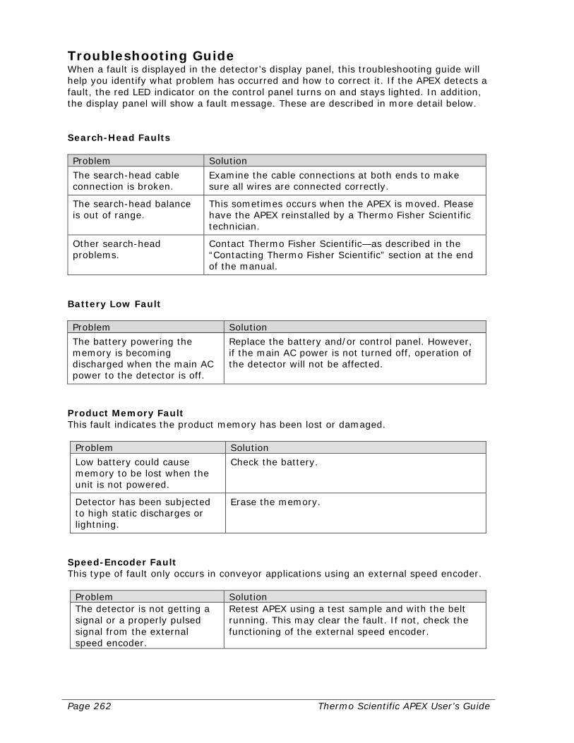
Page 262 Thermo Scientific APEX User’s Guide
Troubleshooting Guide When a fault is displayed in the detector’s display panel, this troubleshooting guide will help you identify what problem has occurred and how to correct it. If the APEX detects a fault, the red LED indicator on the control panel turns on and stays lighted. In addition, the display panel will show a fault message. These are described in more detail below. Search-Head Faults Problem Solution
The search-head cable connection is broken.
Examine the cable connections at both ends to make sure all wires are connected correctly.
The search-head balance is out of range.
This sometimes occurs when the APEX is moved. Please have the APEX reinstalled by a Thermo Fisher Scientific technician.
Other search-head problems.
Contact Thermo Fisher Scientific—as described in the “Contacting Thermo Fisher Scientific” section at the end of the manual.
Battery Low Fault Problem Solution
The battery powering the memory is becoming discharged when the main AC power to the detector is off.
Replace the battery and/or control panel. However, if the main AC power is not turned off, operation of the detector will not be affected.
Product Memory Fault This fault indicates the product memory has been lost or damaged.
Problem Solution
Low battery could cause memory to be lost when the unit is not powered.
Check the battery.
Detector has been subjected to high static discharges or lightning.
Erase the memory.
Speed-Encoder Fault This type of fault only occurs in conveyor applications using an external speed encoder.
Problem Solution The detector is not getting a signal or a properly pulsed signal from the external speed encoder.
Retest APEX using a test sample and with the belt running. This may clear the fault. If not, check the functioning of the external speed encoder.
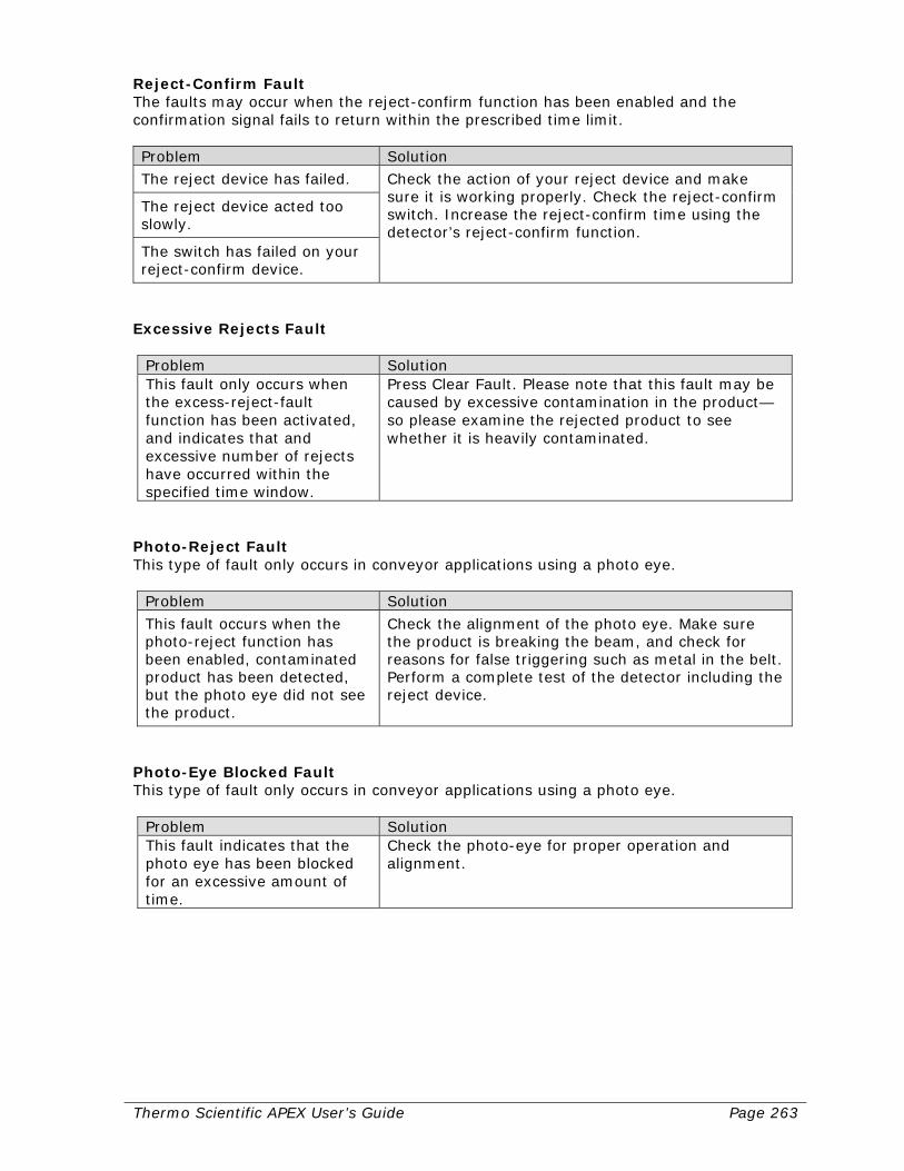
Thermo Scientific APEX User’s Guide Page 263
Reject-Confirm Fault The faults may occur when the reject-confirm function has been enabled and the confirmation signal fails to return within the prescribed time limit. Problem Solution
The reject device has failed. Check the action of your reject device and make sure it is working properly. Check the reject-confirm switch. Increase the reject-confirm time using the detector’s reject-confirm function.
The reject device acted too slowly.
The switch has failed on your reject-confirm device.
Excessive Rejects Fault
Problem Solution This fault only occurs when the excess-reject-fault function has been activated, and indicates that and excessive number of rejects have occurred within the specified time window.
Press Clear Fault. Please note that this fault may be caused by excessive contamination in the product—so please examine the rejected product to see whether it is heavily contaminated.
Photo-Reject Fault This type of fault only occurs in conveyor applications using a photo eye.
Problem Solution
This fault occurs when the photo-reject function has been enabled, contaminated product has been detected, but the photo eye did not see the product.
Check the alignment of the photo eye. Make sure the product is breaking the beam, and check for reasons for false triggering such as metal in the belt. Perform a complete test of the detector including the reject device.
Photo-Eye Blocked Fault This type of fault only occurs in conveyor applications using a photo eye.
Problem Solution This fault indicates that the photo eye has been blocked for an excessive amount of time.
Check the photo-eye for proper operation and alignment.
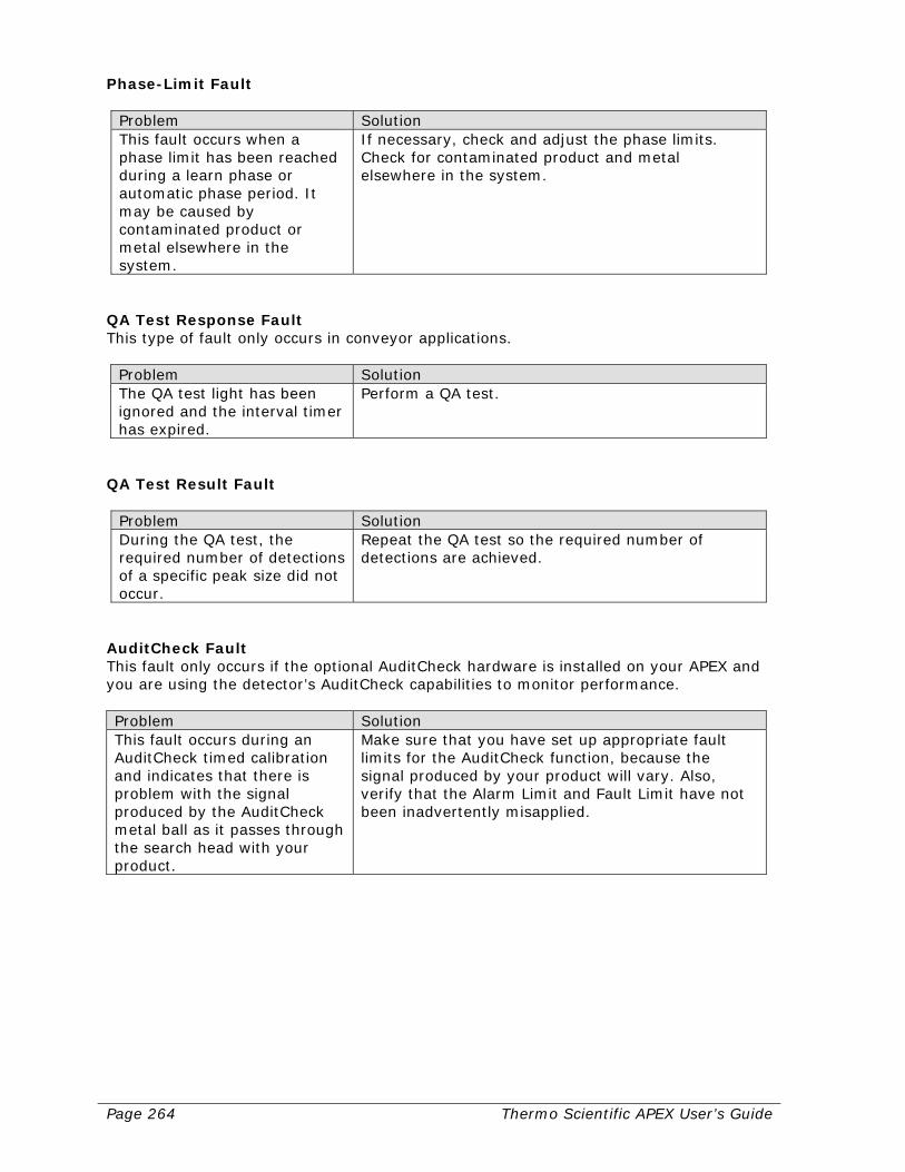
Page 264 Thermo Scientific APEX User’s Guide
Phase-Limit Fault
Problem Solution This fault occurs when a phase limit has been reached during a learn phase or automatic phase period. It may be caused by contaminated product or metal elsewhere in the system.
If necessary, check and adjust the phase limits. Check for contaminated product and metal elsewhere in the system.
QA Test Response Fault This type of fault only occurs in conveyor applications.
Problem Solution The QA test light has been ignored and the interval timer has expired.
Perform a QA test.
QA Test Result Fault
Problem Solution During the QA test, the required number of detections of a specific peak size did not occur.
Repeat the QA test so the required number of detections are achieved.
AuditCheck Fault This fault only occurs if the optional AuditCheck hardware is installed on your APEX and you are using the detector’s AuditCheck capabilities to monitor performance. Problem Solution This fault occurs during an AuditCheck timed calibration and indicates that there is problem with the signal produced by the AuditCheck metal ball as it passes through the search head with your product.
Make sure that you have set up appropriate fault limits for the AuditCheck function, because the signal produced by your product will vary. Also, verify that the Alarm Limit and Fault Limit have not been inadvertently misapplied.
Thermo Scientific APEX User’s Guide Page 265
Service, Repair, and Replacement Parts Listed below is information about how to get help servicing, repairing, and obtaining replacement parts for your APEX. In addition, Thermo Fisher Scientific provides experienced, on-site service technicians, who can assist you installing, setting up, calibrating, maintaining, and repairing your APEX. They can also help you train your operators and solve virtually any APEX-related problem.
Parts List Is Provided For a detailed list of the spare parts available for your APEX, please refer to the Parts List in the “Supplemental Information” section at the end of the manual.
Forms Needed for Repairs or Returns Before returning any equipment to Thermo Fisher Scientific, you must contact your nearest Thermo Fisher Scientific Office for an RMA number, which will authorize you to make the return. In addition, you will need to complete the appropriate Return Material Authorization (RMA) form, Product Information Sheet, and Decontamination Declaration Form, which are shown on the following pages, before returning any equipment to Thermo Fisher Scientific.
Contacting Thermo Fisher Scientific Please refer to the “Contacting Thermo Fisher Scientific” section on page 399 of the manual.
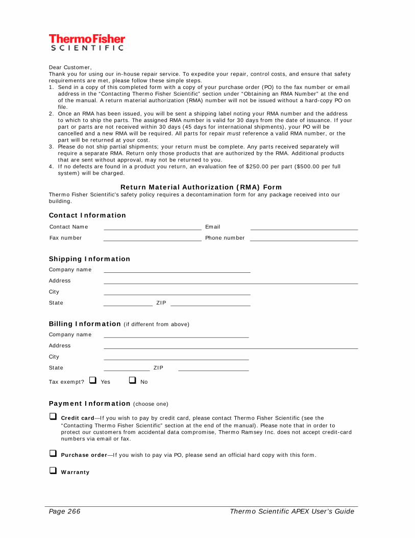
Page 266 Thermo Scientific APEX User’s Guide
Dear Customer, Thank you for using our in-house repair service. To expedite your repair, control costs, and ensure that safety requirements are met, please follow these simple steps. 1. Send in a copy of this completed form with a copy of your purchase order (PO) to the fax number or email
address in the “Contacting Thermo Fisher Scientific” section under “Obtaining an RMA Number” at the end of the manual. A return material authorization (RMA) number will not be issued without a hard-copy PO on file.
2. Once an RMA has been issued, you will be sent a shipping label noting your RMA number and the address to which to ship the parts. The assigned RMA number is valid for 30 days from the date of issuance. If your part or parts are not received within 30 days (45 days for international shipments), your PO will be cancelled and a new RMA will be required. All parts for repair must reference a valid RMA number, or the part will be returned at your cost.
3. Please do not ship partial shipments; your return must be complete. Any parts received separately will require a separate RMA. Return only those products that are authorized by the RMA. Additional products that are sent without approval, may not be returned to you.
4. If no defects are found in a product you return, an evaluation fee of $250.00 per part ($500.00 per full system) will be charged.
Return Material Authorization (RMA) Form
Thermo Fisher Scientific’s safety policy requires a decontamination form for any package received into our building. Contact Information
Contact Name Email
Fax number Phone number Shipping Information
Company name
Address
City
State ZIP Billing Information (if different from above)
Company name
Address
City
State ZIP
Tax exempt? Yes No Payment Information (choose one)
Credit card—If you wish to pay by credit card, please contact Thermo Fisher Scientific (see the “Contacting Thermo Fisher Scientific” section at the end of the manual). Please note that in order to protect our customers from accidental data compromise, Thermo Ramsey Inc. does not accept credit-card numbers via email or fax.
Purchase order—If you wish to pay via PO, please send an official hard copy with this form.
Warranty
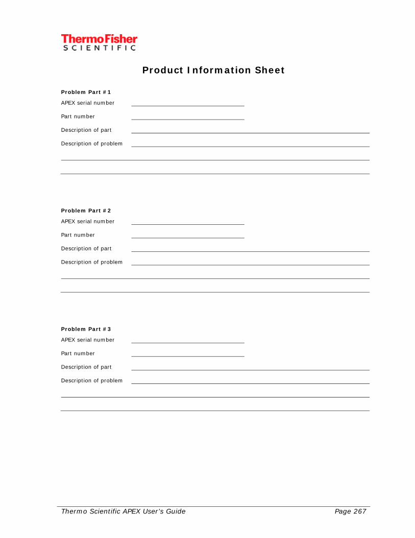
Thermo Scientific APEX User’s Guide Page 267
Product Information Sheet Problem Part #1
APEX serial number Part number Description of part Description of problem
Problem Part #2
APEX serial number Part number Description of part Description of problem
Problem Part #3
APEX serial number Part number Description of part Description of problem
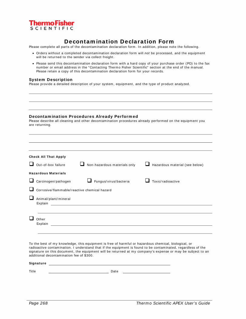
Page 268 Thermo Scientific APEX User’s Guide
Decontamination Declaration Form Please complete all parts of the decontamination declaration form. In addition, please note the following.
• Orders without a completed decontamination declaration form will not be processed, and the equipment will be returned to the sender via collect freight.
• Please send this decontamination declaration form with a hard copy of your purchase order (PO) to the fax number or email address in the “Contacting Thermo Fisher Scientific” section at the end of the manual. Please retain a copy of this decontamination declaration form for your records.
System Description Please provide a detailed description of your system, equipment, and the type of product analyzed.
Decontamination Procedures Already Performed Please describe all cleaning and other decontamination procedures already performed on the equipment you are returning.
Check All That Apply
Out-of-box failure Non-hazardous materials only Hazardous material (see below) Hazardous Materials
Carcinogen/pathogen Fungus/virus/bacteria Toxic/radioactive
Corrosive/flammable/reactive chemical hazard
Animal/plant/mineral Explain
Other Explain
To the best of my knowledge, this equipment is free of harmful or hazardous chemical, biological, or radioactive contamination. I understand that if the equipment is found to be contaminated, regardless of the signature on this document, the equipment will be returned at my company's expense or may be subject to an additional decontamination fee of $300. Signature Title Date
Thermo Scientific APEX User’s Guide Page 269
Ordering Parts For the fastest service when ordering parts, please telephone or fax the nearest Thermo Fisher Scientific office. For the office nearest you, please see the “Contacting Thermo Fisher Scientific” section at the end of the manual. The quickest way to get the parts you need is to do the following. 1) Identify the broken or faulty parts. 2) Locate the parts in the Parts List (in the supplemental information section at the end
of the manual). 3) Find the part numbers for the items you need. 4) Before you contact Thermo Fisher Scientific for your parts, make sure you have the
following information. • Your APEX model and serial number. • Your company’s purchase order (PO) number. • The date the parts are needed. • Your preferred shipping method. • A list of all the part numbers—together with descriptions and the quantities
needed. 5) Contact Thermo Fisher Scientific by telephone or fax—as described in the “Contacting
Thermo Fisher Scientific” section at the end of the manual. Please Note Modifications and repairs should only be performed under the supervision of a Thermo Fisher Scientific Service Engineer and with written consent from Thermo Fisher Scientific. List of Commonly Required APEX Spare Parts Listed below are the commonly required spare parts and fuses used by your APEX. Please only use spare parts as directed by Thermo Fisher Scientific or one of the company’s authorized agents. In addition, please note that PCB’s must be sourced from Thermo Fisher Scientific. Fuses, however, can be sourced from any reputable supplier, providing their rating is identical to the following.
• F1 (PSU PCB)—250 v AC, 3.15 A, 35 A breaking capacity. Typically, the following types of fuses are recommended.
o Bussmann 3.15 A Radial lead micro fuse BK/ETF type o Bussmann 3.15 A Fast acting BK/EFF type o Wickmann 3.15 A Anti-surge TR5 type o Wickmann 3.15 A Fast acting TR5 type o Bussmann PC-Tron 3A type
• F1 to F6 (Relay PCB) 250v AC, 2A.

Page 270 Thermo Scientific APEX User’s Guide

Thermo Scientific APEX User’s Guide Page 271
Installing Your APEX Detector The first thing to do is unpack and inspect your detector and then familiarize yourself with its basic operating, environmental, safety, installation, and wiring requirements. Please read the “Theory of Operation” section, because this will help you properly install the detector as well as operate it successfully. You should also note that one of the keys to making a successful installation is minimizing two types of interference. For example, installing the detector near electric motors (which are a major source of radio-frequency interference) or close to large metal objects will negatively affect its performance. Once you’ve covered the theory part, you’ll move on to the practical “nuts and bolts” details about how to hard wire your detector as described on page 283. Thereafter, you may need to set up and wire in additional components such a product reject device and so on. Please go to page 291 (the “Mechanical Set-Up” section) for more details. For now, let’s get on with unpacking the detector. Your APEX is a sensitive instrument and should not be handled in rough manner. Doing so may affect the integrity of the equipment and cause failure or compromise safety.
Unpacking Your APEX Your APEX metal detector has been properly packaged for shipment. Inspect all packages before opening. If there is any evidence of shipping damage, notify the shipping carrier immediately, because the carrier may be responsible for the damage. Check the contents of the shipment against the order or packing slip. Be sure to look for any accessories, such as reject devices or product tubes ordered and shipped with the detector. Some of the component pieces are small and may be inadvertently discarded with the packaging. Check the equipment for any signs of damage in shipment. If there is any evidence of shipping damage, notify the shipping carrier immediately. Included with each APEX metal detector are the following.
• APEX Metal Detector User’s Guide—the manual you are currently reading. • Quick-Start manual. • Installation and mounting parts. • Metal test samples.
Page 272 Thermo Scientific APEX User’s Guide
List of Included Components Your metal detector comprises the following components.
• Search-Head Case and Coils Products are passed through the aperture of this case. Note: If remote mounting has been specified, there is a separate control unit/PSU (2 m [7 ft] standard cable to 30 m (98 ft) maximum).
• Search-Head PCB
The search-head PCB is the interface to the coils in the search head. It drives the oscillator coils with a radio-frequency signal to produce an alternating magnetic field in the aperture.
• Control Panel The control panel houses the power supply, the I/O PCB, and all processing and display functions.
Safe Storage Conditions for Your APEX Your APEX metal detector and associated equipment can be safely stored in ambient temperatures of -10 to 50° C (14 to 122° F) with a non-condensing humidity of 80%.
APEX Specifications There are three models of APEX—the APEX 500, APEX 300, and APEX 100. The principal difference between the three models has to do with aperture size—the size of the opening through which the product passes to be analyzed for metallic contaminants.
Specifications for the APEX 500, 300, and 100 Listed below are the technical specifications for the APEX 500. Product Speed Depends on product dimension and belt speed Outputs Six NO relays (All available as solid-state open-collector, if required. Contact Thermo Fisher Scientific—as described in the “Contacting Thermo Fisher Scientific” section at the end of the manual—for details.)
• Relays o 250 volt AC 1 amp max o 50 volt DC 1 amp max
• FET
o 30 VDC, 1 amp max (NO compatible) o Output Allocation (Menu selectable) o Reject 1, Reject 2, AuditCheck™, Fault, Alarm, Warning, and QA Lamp
Thermo Scientific APEX User’s Guide Page 273
Inputs (Menu Selectable) Six Inputs, Active 12v DC + 12 volt auxiliary supply for input sensors for the following.
• Belt Speed Sensor (uses 5v auxiliary supply provided) • Keylock • Product Select 1 • Product Select 2 • Infeed photo-eye • Reject Confirmation 1 (bin full) • Reject Confirmation 2 • External Suppression
Electrical Supply 85 to 260 VAC, 47 to 65 Hz, 100 watts maximum Product Speed 0.5 m/min (1.7 ft/min) to 1000 m/min (3,300 ft/min) Air Supply (AuditCheck™) 5.5 bar (80 psi) Environmental
• Operating Temperature o -10° C to + 40° C (+14° F to +104° F)
• Relative Humidity o 0% to 80% non-condensing o 80% to temperatures to 31° C (87° F) decreasing linearly to 50% relative
humidity at 40° C (104° F) Maximum Surface Temperature 60° C (140° F) Altitude Up to 2000 m (1.2 miles) Location Indoor or outdoor use. Direct sunlight on the aperture could cause problems. Protect the equipment from direct sunlight. Environmental Protection IEC60529:IP66 NEMA 4X Ventilation None required
Page 274 Thermo Scientific APEX User’s Guide
Front Panel Manufacturers: GE Plastics, Chi Mei Material reference: Cycolac, Polylac 757 Surface treatments: None Operating temperature: Continuous at 80° C (176° F) Battery Approved type according to Table 3 of IEC 60086-1 Type E. Battery type: Sonnenschein SL-350 PCRN Nominal voltage: 3.6 V Electrochemical system: Lithium thionyl-chloride Rated capacity: 1000 mA-hours
Standard Features and Options Listed below are the standard features and options available for your APEX 500, 300, and 100 detector. Standard Features Your APEX included the following standard features.
• Patented multi-coil design • Ease of operation. • Reject confirmation. • Product capacity of 100. • Variable speed operation. • Dual frequency/dual gain. • Epoxy-lined head rated to IP66. • Two independent reject outputs. • Quality test on consecutive units of product. • Icons with help text in ten languages. • Sensitivity performance enhancement. • Reject inhibit to prove reject verification system. • AuditCheck™ and quality-assurance rejects to a separate reject bin. • A bright display with a wide viewing-angle.
Statistics and Information Your APEX provides the following user information and statistics.
• Current product name. • Total number of rejected units of product. • Number of units of product rejected by the quality test. • Number of units of product rejected by AuditCheck™. • Number of units of product passed (when in package mode). • Error messages using LEDs and warning screens.
Thermo Scientific APEX User’s Guide Page 275
Options Optional features of your APEX are as follows.
• Remote control panel located up to 30 meters away. • Certified test spheres. • White polypropylene aperture liner. • AuditCheck™ performance validation system. • Conversion kits to change a DSP3 to an APEX. • Field compression flanges, which reduce the metal-free zone.
Printer Options A local rewind or remote printer option is available. In addition, the printer is able to print batch reports. Printouts are available in one of ten languages.
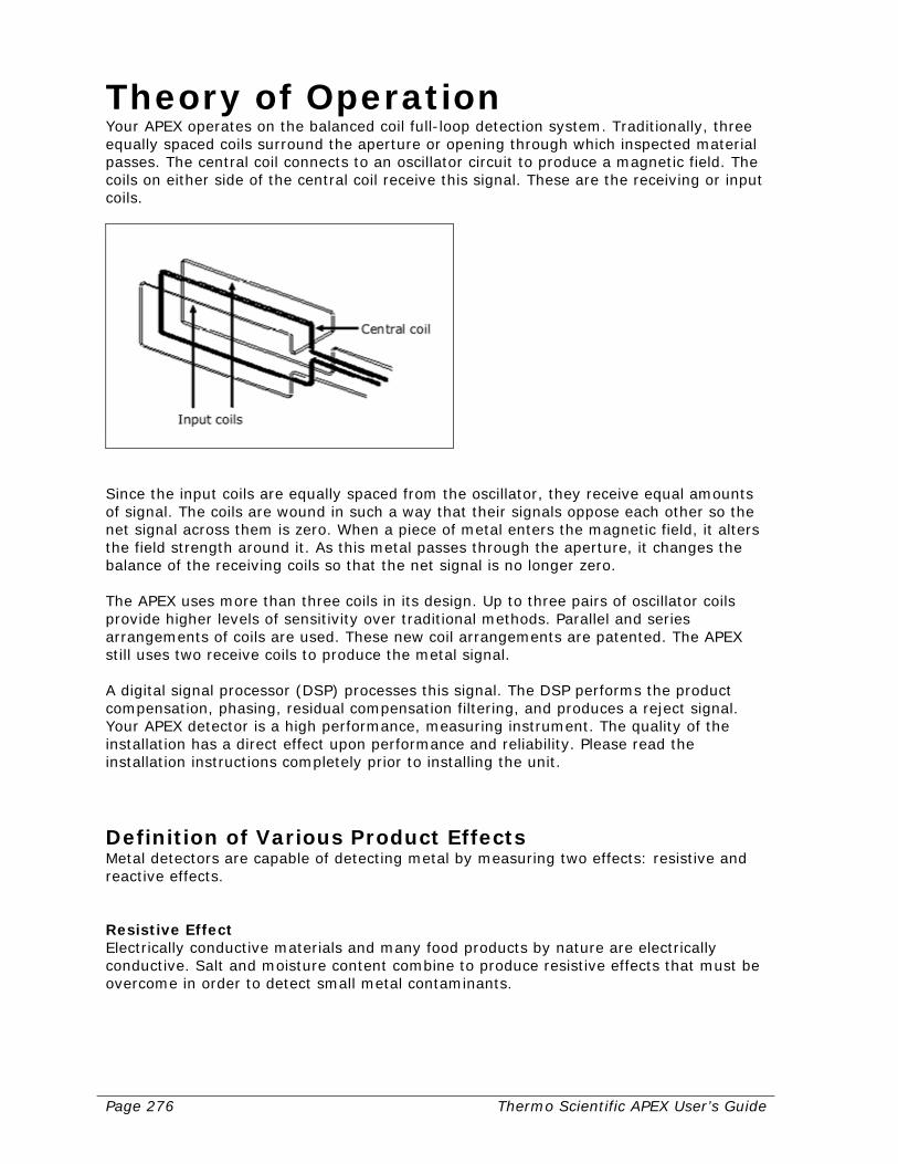
Page 276 Thermo Scientific APEX User’s Guide
Theory of Operation Your APEX operates on the balanced coil full-loop detection system. Traditionally, three equally spaced coils surround the aperture or opening through which inspected material passes. The central coil connects to an oscillator circuit to produce a magnetic field. The coils on either side of the central coil receive this signal. These are the receiving or input coils.
Since the input coils are equally spaced from the oscillator, they receive equal amounts of signal. The coils are wound in such a way that their signals oppose each other so the net signal across them is zero. When a piece of metal enters the magnetic field, it alters the field strength around it. As this metal passes through the aperture, it changes the balance of the receiving coils so that the net signal is no longer zero. The APEX uses more than three coils in its design. Up to three pairs of oscillator coils provide higher levels of sensitivity over traditional methods. Parallel and series arrangements of coils are used. These new coil arrangements are patented. The APEX still uses two receive coils to produce the metal signal. A digital signal processor (DSP) processes this signal. The DSP performs the product compensation, phasing, residual compensation filtering, and produces a reject signal. Your APEX detector is a high performance, measuring instrument. The quality of the installation has a direct effect upon performance and reliability. Please read the installation instructions completely prior to installing the unit.
Definition of Various Product Effects Metal detectors are capable of detecting metal by measuring two effects: resistive and reactive effects. Resistive Effect Electrically conductive materials and many food products by nature are electrically conductive. Salt and moisture content combine to produce resistive effects that must be overcome in order to detect small metal contaminants.
Thermo Scientific APEX User’s Guide Page 277
Reactive Effect Ferro-magnetic and electrically conductive materials produce reactive effects. Iron is both electrically conductive and ferro-magnetic. The effect for small iron particles is ferro-magnetic, which is largely opposite that of a metal such as copper. Copper is a strong electrical conductor. Dry Products Dry products produce very little, or zero product effect. Examples of dry products are some tablets, cookies, candy, chocolate, dry powders, oil-based products such as peanut butter, and cereals. Wet Products Wet products produce a larger product effect. Examples of wet products are bread, buns, cakes, meat, and dairy products. Metal Film Products Products packaged using metallic wrappers usually require a low search-head frequency such as 50 kHz.
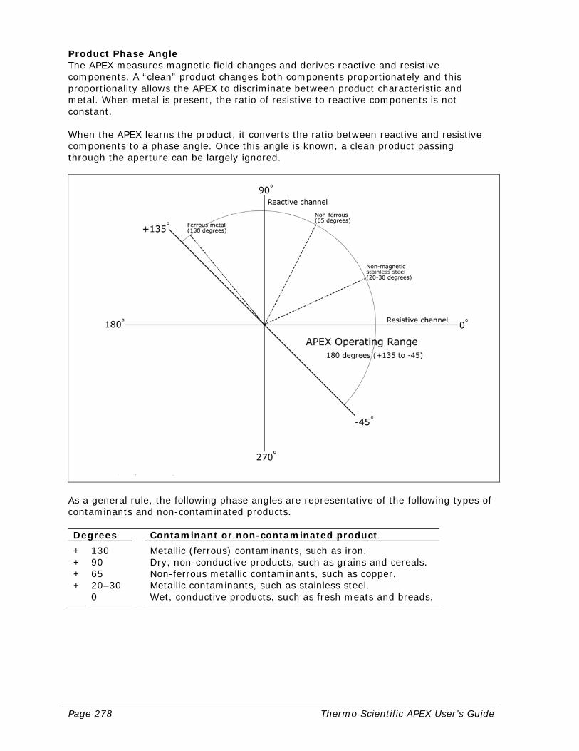
Page 278 Thermo Scientific APEX User’s Guide
Product Phase Angle The APEX measures magnetic field changes and derives reactive and resistive components. A “clean” product changes both components proportionately and this proportionality allows the APEX to discriminate between product characteristic and metal. When metal is present, the ratio of resistive to reactive components is not constant. When the APEX learns the product, it converts the ratio between reactive and resistive components to a phase angle. Once this angle is known, a clean product passing through the aperture can be largely ignored.
As a general rule, the following phase angles are representative of the following types of contaminants and non-contaminated products. Degrees Contaminant or non-contaminated product
+ 130 Metallic (ferrous) contaminants, such as iron. + 90 Dry, non-conductive products, such as grains and cereals. + 65 Non-ferrous metallic contaminants, such as copper. + 20–30 Metallic contaminants, such as stainless steel. 0 Wet, conductive products, such as fresh meats and breads.
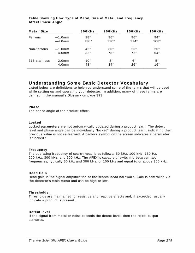
Thermo Scientific APEX User’s Guide Page 279
Table Showing How Type of Metal, Size of Metal, and Frequency Affect Phase Angle
Metal/Size 300KHz 200KHz 150KHz 100KHz
Ferrous —1.0mm 98° 96° 96° 94° —4.0mm 130° 120° 114° 108° Non-ferrous —1.0mm 42° 30° 25° 20° —4.0mm 82° 78° 72° 64° 316 stainless —2.0mm 10° 8° 6° 5° —4.0mm 48° 34° 26° 16°
Understanding Some Basic Detector Vocabulary Listed below are definitions to help you understand some of the terms that will be used while setting up and operating your detector. In addition, many of these terms are defined in the manual’s Glossary on page 393. Phase The phase angle of the product effect. Locked Locked parameters are not automatically updated during a product learn. The detect level and phase angle can be individually “locked” during a product learn, indicating their previous value is not re-learned. A padlock symbol on the screen indicates a parameter is “locked.” Frequency The operating frequency of search head is as follows: 50 kHz, 100 kHz, 150 Hz, 200 kHz, 300 kHz, and 500 kHz. The APEX is capable of switching between two frequencies, typically 50 kHz and 300 kHz, or 100 kHz and equal to or above 300 kHz. Head Gain Head gain is the signal amplification of the search-head hardware. Gain is controlled via the detector’s main menu and can be high or low. Thresholds Thresholds are maintained for resistive and reactive effects and, if exceeded, usually indicate a product is present. Detect level If the signal from metal or noise exceeds the detect level, then the reject output activates.
Page 280 Thermo Scientific APEX User’s Guide
Safety Precautions Listed below are the safety precautions for your APEX detector. Please read them carefully, because this information is important—for your own personal safety and the safety of others.
General Safety Precautions Do not install, operate, or perform any maintenance procedures until you have read the safety precautions listed below. Warning Failure to follow safe installation and servicing procedures could result in death or serious injury.
• Make certain only qualified personnel perform installation and maintenance procedures in accordance with the instruction in this manual.
• Allow only qualified electricians to open and work in the electronics cabinets,
power supply cabinet, control cabinet, or switch boxes. • Covers over the electronics and rotating parts must always remain in place
during normal operation. Remove only for maintenance, with the machine’s power OFF. Replace all covers before resuming operation.
• During maintenance, a safety tag (not supplied by the factory) to be displayed in
the ON/OFF switch areas instructing others not to operate the unit (ANSI:B157.1).
Warning High voltage that may be present on leads could cause electrical shock.
• All switches must be OFF when checking input AC electrical connections, removing or inserting printed circuit boards, or attaching voltmeters to the system.
• Use extreme caution when testing in, on, or around the electronics cabinet, PC
boards, or modules. There are voltages in excess of 115 V or 230 V in these areas.
Warning Use only the procedures and new parts specifically referenced in this manual to ensure specification performance and certification compliance. Unauthorized procedures or parts can render the instrument dangerous to life, limb, or property. Warning Keep hands and clothing away from all moving or rotating parts.
Thermo Scientific APEX User’s Guide Page 281
Warning Do not place or store objects of any kind on the machine. Warning This machine should not be operated at more than the production rate stated on your Equipment Specification sheet, used in applications other than those stated in the original order, or in a manner not specified by Thermo Fisher Scientific. To do so may impair the protection provided by the machine. Warning The APEX is cCSAus and CE approved and can be used in environments containing combustible dusts. All modifications to the APEX must be approved in writing from Thermo Fisher Scientific. This is to prevent any possibility of a modification causing a breach of the integrity of the equipment, which might lead to the ignition of dust or other safety infringement.
Specific Safety Precautions The precautions listed below are specific to the APEX. Read them carefully before using the machine. Warning Humidity can cause surfaces of the detector to become damp, which in turn can attract deposits of dust. Dust layers may be regarded as unhygienic and can be an explosion hazard. Please ensure the APEX surfaces are regularly checked for build-up of dust and any dust layers that form should be removed. Warning The ambient temperature for the APEX operation is –10 ° C to +40° C (14° F to 104°F). The APEX will not produce surface temperatures greater than +60° C (140° F) at an ambient temperature of +40° C (104° F). If APEX is used in a Zone 22 combustible dust environment, ensure the ambient temperature does not exceed +40° C (104° F). Warning The aperture is normally sealed with resin epoxy having a thermal stability adequate for the temperature of most products on conveyor belts under all operational conditions. However, some products may be “hot” when passing through the aperture and this may eventually degrade the resin epoxy. Ensure “hot” products passing through the aperture do not raise the surface temperature of the resin above +60° C (140° F). An aperture liner that protects the resin may be required if the product temperature is too high.

Page 282 Thermo Scientific APEX User’s Guide
Thermo Scientific APEX User’s Guide Page 283
Electrical Set-Up All wiring, except as noted, is the responsibility of the customer. Detailed below are the general electrical requirements and the types of supply voltage and connections needed when installing your APEX detector. Please follow these requirements carefully—for your own personal safety and the safety of others. In the following instructions, the acronym “PSU” refers to the detector’s power supply unit, “PCB” refers to a printed circuit-board, and “PCB–A” refers to a printed circuit board assembly.
Potential Causes of Interference The detector is a balanced alternating-current magnetic sensor, and—as a result—is subject to interference from a variety of external mechanical, electrical, and magnetic sources. These potential sources of interference are described in more detail below. Mechanical Vibration Mechanical vibration induces alternating-current eddy patterns in the detector’s metal case, which may interfere with the detector’s X-channel. If the vibration is severe, the R-channel may also be affected. Electro-Magnetic Induction When electro-magnetic currents are induced in external hardware and cables, this may cause three types of interference, as follows.
• “Dirty” Power Lines This type of interference may occur when several pieces of equipment are connected to the same power line. In most cases, variable-frequency drive motors are the culprits. In general, any equipment that utilizes switching technology is a potential source of contamination. Both the X- and R-channel may be affected.
• Magnetic Fields Caused by High Currents in Wires and Cables (Near-Fields) When high electrical currents pass through wires and cables they create magnetic fields, known as “near-fields.” These near-fields may interfere with the detector’s X- and R-channels, especially when high-current cables lie in close proximity to the detector.
• Electromagnetic Waves This source of interference is less common, but is still a valid concern—especially when the external wave interferes with a vital internal frequency in the detector’s circuitry. Both the X- and R-channel may be affected.
Alternating Conducting Loops Alternating conducting loops (known as “loop effects”) may create noise in the detector. A loop effect may be created when a conductive path that varies in time, lies in close proximity to the detector. When a loop effect is created, the X-channel is the one most likely to be affected.

Page 284 Thermo Scientific APEX User’s Guide
Static Electricity Sometimes, in conveyor applications, static electricity is generated when the belt and slider-bed rub against each other. Because a moving or static charge is a form of electrical current, moving or static charges may produce a magnetic field that randomly interferes with the magnetic field produced by the search head. This type of interference creates noise in the detector and may affect both the X- and R-channel. Moving Metal When metal moves through a magnetic field, it creates a current. Thus, any metal that moves near the detector may cause interference in the detector—interference that is easily confused with the effects of vibration. Permanent Magnets and Electro-Magnets If permanent magnets and electro-magnets are allowed near the detector, they can cause interference—especially those that move or are situated very close to the detector. Interference from these sources may affect with the detector’s X- and R-channels.
General Electrical Requirements When choosing the AC power line for the detector, note that starting heavy electrical machinery creates momentary volt-drops in the line. Such spikes can cause the detector to trigger.
• When the control unit is mounted remotely from the search head, the cable connecting it to the search head is of a specific type. Do not substitute or splice on extra cable. Cable can be cut to length and is not sensitive to movement. If required, contact Thermo Fisher Scientific—as described in the “Contacting Thermo Fisher Scientific” section at the end of the manual—for extra cable or cable information.
• Be sure to observe the following critical wiring conditions to ensure proper
connection of your detector • Ensure main power is OFF. • Earth all enclosures and conduits. An earth connection between all metal conduits
is required. • Connect the shields only where shown. • Check that all wires are tight in their connections. • Never use a “megger” to check the wiring. • All conduits should enter the bottom of the enclosure. Do not run conduit through
the top or sides of the enclosure.

Thermo Scientific APEX User’s Guide Page 285
Caution Externally connected appliances shall comply with their relevant safety requirements. Please ensure appliances (such as solenoids and photo-eyes) are rated for the voltage they will be connected to and the field wiring into the search head is appropriately rated in terms of current and insulation. Caution Ensure that AC power (mains) supply fluctuations do not exceed ± 10% of the nominal voltage. Caution Do not install the APEX in a position that makes it hard to use the AC mains isolator. Note: The normal level of transient over voltages is impulse withstand (over voltage) category II of IEC 60364-4-443. Note: Elsewhere in this manual are instructions for correct termination of cables. The APEX does not use plugs and sockets for connection of external field wiring. If such a method is required, contact Thermo Fisher Scientific—as described in the “Contacting Thermo Fisher Scientific” section at the end of the manual—for recommended methods.
Supply Voltage and Connections Given below are the requirements for the voltage supply and connections to your APEX detector.
• Input supply voltage range should not be outside the range 85VAC to 264VAC. • We recommend the APEX be fed from a clean AC supply and left powered. • Connections are made inside the control panel on the PSU PCB. Do not “tee” off
with wiring for other external electrical equipment (even other metal detectors). • When choosing the AC power line for the detector, note that starting heavy
electrical machinery can create considerable (though momentary) volt-drops in the line. This can cause the detector to trigger. Since detector power consumption is only 35 watts, it is recommended that a lighting circuit be used rather than machinery power circuit. Where this is not possible and line noise triggers the detector, contact Thermo Fisher Scientific—as described in the “Contacting Thermo Fisher Scientific” section at the end of the manual—for recommendations about a suitable isolation transformer or power-line filter.
Note: Do not use loads requiring power sources not generated or used by the APEX, unless approved by Thermo Fisher Scientific.
Page 286 Thermo Scientific APEX User’s Guide
System Grounding On all metal detection systems, it is important for safety and performance to implement good grounding techniques. This should be made at the appropriate point at the PSU PCB. Care must also be taken to ensure that the head or frame does not carry earth fault or operating currents from other systems. Earth ground connections should be made at one point in the system, and this point is the PSU PCB. Use waterproof cable glands at all cable entries. Recommended cable entries are listed in this manual on page 288. Caution All wiring must be done in accordance with field wiring diagrams, the National Electrical Code, and all local electrical codes. Do not route coil cables through the same conduit with power cables or any large source of electrical noise.
Removing the Control Panel Before removing the control panel, make sure the AC power supply is off. The control panel is held in place with eight mounting bolts. Remove these bolts to gain access to the search-head power supply unit (PSU) and relay printed circuit boards (PCBs). Remote search heads have a separate control panel to access the PSU and relay PCBs. Note: The control panel also has internal PCBs for the operator display, keypad, and signal processing. If any of these items need replacing, disconnect the PSU and search-head cables that connect to them. Caution: When removing or working with the control panel be careful when tightening the screws. Do not tighten them too tight or breakage will occur. Caution: When removing the PSU PCB, ensure that star (crinkle) washers are used on the two PCB-mounting pillars adjacent to J1 (mains AC power in) and J2. Additionally, ensure that pillars between relay PCB and PSU PCB are properly tightened and secured. AC Power Wiring The detector power consumption is only 35 watts. It is recommended a lighting circuit be used rather than a machinery power circuit. If this is not possible, and the line noise triggers the detector, contact Thermo Fisher Scientific—as described in the “Contacting Thermo Fisher Scientific” section at the end of the manual—for recommendations of a suitable isolation transformer or power-line filter.
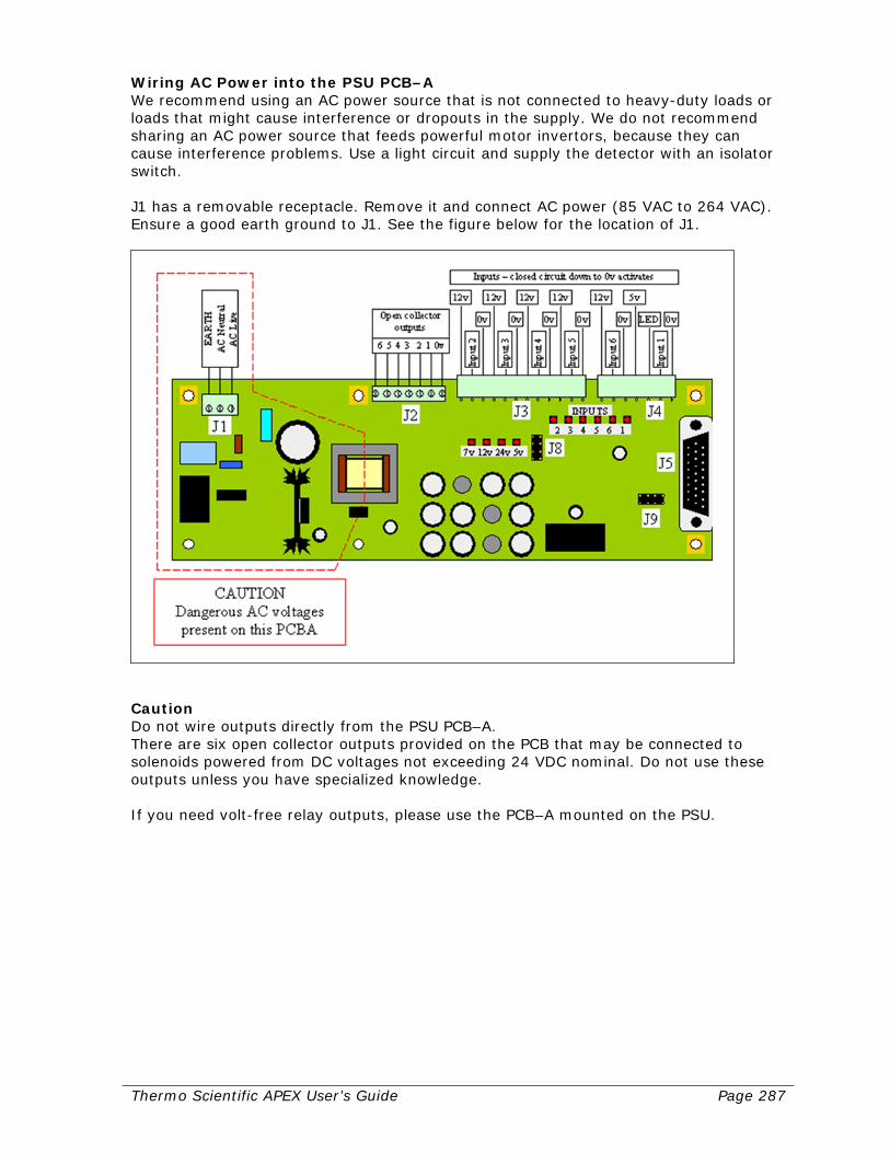
Thermo Scientific APEX User’s Guide Page 287
Wiring AC Power into the PSU PCB–A We recommend using an AC power source that is not connected to heavy-duty loads or loads that might cause interference or dropouts in the supply. We do not recommend sharing an AC power source that feeds powerful motor invertors, because they can cause interference problems. Use a light circuit and supply the detector with an isolator switch. J1 has a removable receptacle. Remove it and connect AC power (85 VAC to 264 VAC). Ensure a good earth ground to J1. See the figure below for the location of J1.
Caution Do not wire outputs directly from the PSU PCB–A. There are six open collector outputs provided on the PCB that may be connected to solenoids powered from DC voltages not exceeding 24 VDC nominal. Do not use these outputs unless you have specialized knowledge. If you need volt-free relay outputs, please use the PCB–A mounted on the PSU.
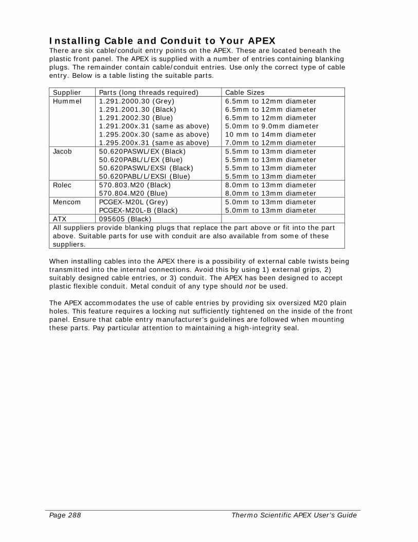
Page 288 Thermo Scientific APEX User’s Guide
Installing Cable and Conduit to Your APEX There are six cable/conduit entry points on the APEX. These are located beneath the plastic front panel. The APEX is supplied with a number of entries containing blanking plugs. The remainder contain cable/conduit entries. Use only the correct type of cable entry. Below is a table listing the suitable parts. Supplier Parts (long threads required) Cable Sizes Hummel 1.291.2000.30 (Grey)
1.291.2001.30 (Black) 1.291.2002.30 (Blue) 1.291.200x.31 (same as above) 1.295.200x.30 (same as above) 1.295.200x.31 (same as above)
6.5mm to 12mm diameter 6.5mm to 12mm diameter 6.5mm to 12mm diameter 5.0mm to 9.0mm diameter 10 mm to 14mm diameter 7.0mm to 12mm diameter
Jacob 50.620PASWL/EX (Black) 50.620PABL/L/EX (Blue) 50.620PASWL/EXSI (Black) 50.620PABL/L/EXSI (Blue)
5.5mm to 13mm diameter 5.5mm to 13mm diameter 5.5mm to 13mm diameter 5.5mm to 13mm diameter
Rolec 570.803.M20 (Black) 570.804.M20 (Blue)
8.0mm to 13mm diameter 8.0mm to 13mm diameter
Mencom PCGEX-M20L (Grey) PCGEX-M20L-B (Black)
5.0mm to 13mm diameter 5.0mm to 13mm diameter
ATX 095605 (Black) All suppliers provide blanking plugs that replace the part above or fit into the part above. Suitable parts for use with conduit are also available from some of these suppliers.
When installing cables into the APEX there is a possibility of external cable twists being transmitted into the internal connections. Avoid this by using 1) external grips, 2) suitably designed cable entries, or 3) conduit. The APEX has been designed to accept plastic flexible conduit. Metal conduit of any type should not be used. The APEX accommodates the use of cable entries by providing six oversized M20 plain holes. This feature requires a locking nut sufficiently tightened on the inside of the front panel. Ensure that cable entry manufacturer’s guidelines are followed when mounting these parts. Pay particular attention to maintaining a high-integrity seal.
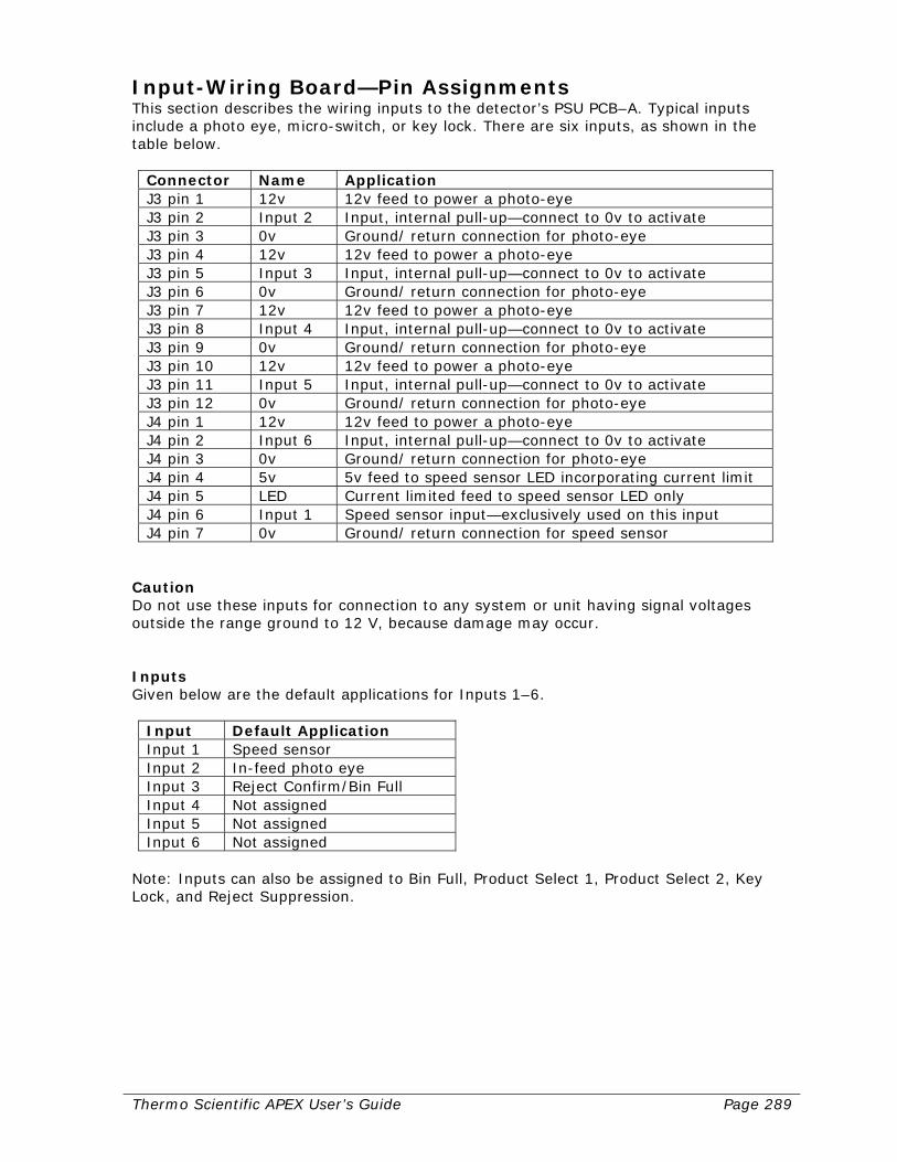
Thermo Scientific APEX User’s Guide Page 289
Input-Wiring Board—Pin Assignments This section describes the wiring inputs to the detector’s PSU PCB–A. Typical inputs include a photo eye, micro-switch, or key lock. There are six inputs, as shown in the table below.
Connector Name Application J3 pin 1 12v 12v feed to power a photo-eye J3 pin 2 Input 2 Input, internal pull-up—connect to 0v to activate J3 pin 3 0v Ground/ return connection for photo-eye J3 pin 4 12v 12v feed to power a photo-eye J3 pin 5 Input 3 Input, internal pull-up—connect to 0v to activate J3 pin 6 0v Ground/ return connection for photo-eye J3 pin 7 12v 12v feed to power a photo-eye J3 pin 8 Input 4 Input, internal pull-up—connect to 0v to activate J3 pin 9 0v Ground/ return connection for photo-eye J3 pin 10 12v 12v feed to power a photo-eye J3 pin 11 Input 5 Input, internal pull-up—connect to 0v to activate J3 pin 12 0v Ground/ return connection for photo-eye J4 pin 1 12v 12v feed to power a photo-eye J4 pin 2 Input 6 Input, internal pull-up—connect to 0v to activate J4 pin 3 0v Ground/ return connection for photo-eye J4 pin 4 5v 5v feed to speed sensor LED incorporating current limit J4 pin 5 LED Current limited feed to speed sensor LED only J4 pin 6 Input 1 Speed sensor input—exclusively used on this input J4 pin 7 0v Ground/ return connection for speed sensor
Caution Do not use these inputs for connection to any system or unit having signal voltages outside the range ground to 12 V, because damage may occur. Inputs Given below are the default applications for Inputs 1–6.
Input Default Application Input 1 Speed sensor Input 2 In-feed photo eye Input 3 Reject Confirm/Bin Full Input 4 Not assigned Input 5 Not assigned Input 6 Not assigned
Note: Inputs can also be assigned to Bin Full, Product Select 1, Product Select 2, Key Lock, and Reject Suppression.
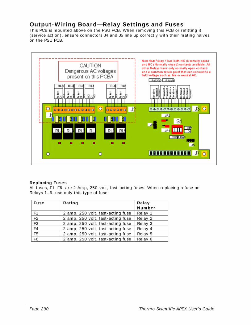
Page 290 Thermo Scientific APEX User’s Guide
Output-Wiring Board—Relay Settings and Fuses This PCB is mounted above on the PSU PCB. When removing this PCB or refitting it (service action), ensure connectors J4 and J5 line up correctly with their mating halves on the PSU PCB.
Replacing Fuses All fuses, F1–F6, are 2 Amp, 250-volt, fast-acting fuses. When replacing a fuse on Relays 1–6, use only this type of fuse.
Fuse Rating Relay Number
F1 2 amp, 250 volt, fast-acting fuse Relay 1 F2 2 amp, 250 volt, fast-acting fuse Relay 2 F3 2 amp, 250 volt, fast-acting fuse Relay 3 F4 2 amp, 250 volt, fast-acting fuse Relay 4 F5 2 amp, 250 volt, fast-acting fuse Relay 5 F6 2 amp, 250 volt, fast-acting fuse Relay 6

Thermo Scientific APEX User’s Guide Page 291
Mechanical Set-Up Instructions for Specific Applications Now that you have completed the electrical installation of your APEX detector, the next step is to complete the mechanical installation. The type of mechanical set-up required depends on which type of application you are installing—a conveyor, a gravity-feed, a pipeline, or pharmaceutical application. Find the relevant mechanical set-up instructions as follows.
• Conveyor applications—Go to the page that follows this one (page 292). • Gravity-feed and pharmaceutical applications—Go to page 299. • Pipeline applications—Go to page 307.
Page 292 Thermo Scientific APEX User’s Guide
Mechanical Set-Up for Conveyor Applications The APEX with options is easily integrated into most conveyor line systems and requires a minimal amount of adjustment. Correctly installed, the metal detector will operate reliably for long periods without attention. The customer is responsible for initial inspection of the equipment and site preparation. It is essential that the customer place the equipment in the production line in accordance with the guidelines below. The customer must assure that qualified service personnel are available to make interconnections with other production equipment and perform work at the installation site. A Thermo Fisher Scientific Products Customer Service Representative is available to supervise installation and verify operation, as well as train personnel assigned to operate and maintain the equipment.
APEX Installation Considerations Customers who intend to install the APEX on an existing conveyor or a Thermo Fisher Scientific-supplied conveyor, should study the following factors that can influence the detector’s performance. The importance of studying this section and taking note of the information given is very important. It has been proven that faulty metal detector operation, such as random false alarm signals and undue sensitivity to vibration, are usually due to incorrect installation of the metal detector or some other factors external to the metal detector itself. Location of the Detector The APEX should be located to give easy access to the front panel. The installation location of the display and/or electronics box should be considered. Mounting the APEX For trouble free and reliable operation, it is very important that the APEX be correctly mounted. The support structure for mounting the APEX must transmit a minimum amount of vibration to the metal detector. This structure must be flat and parallel, thereby minimizing possible twisting torques to the metal detector case, which can distort the electromagnetic field and cause false triggering. While the APEX and the support structure may remain in contact, nothing, including the product, must be allowed to touch any part of the aperture, as this could cause wear of the aperture lining and give random false alarms. Any pressure, torque, or electrical ground will cause the APEX to misfire. Any support platform, guide rails, or conveyor belt (including the joint in the belt) which passes through the aperture must be completely free of all metal, and must not touch any part of the aperture at any time. The packaging on any product to be inspected must be completely free of any metal such as clips, aluminum foil, metallic labels, staples, and lids. Metal-Free Area For optimum performance, non-moving metal should be allowed no closer to the aperture opening than 1.5 times the smallest aperture height, measured outward from the center of the aperture. Moving metal should be allowed no closer to the aperture opening than 2.0 times the smallest aperture height, measured outward from the center

Thermo Scientific APEX User’s Guide Page 293
of the aperture. When a complete conveyor system has been supplied by Thermo Fisher Scientific, these considerations have already been factored in to the design of the system. Factors That Can Influence the Operation of the Detector It has been proven that causes external to the APEX, are the main reasons for faulty operation or random false triggering. When installing the APEX on an existing or custom-built conveyor system, this information below should be carefully studied. Only when correctly installed will the equipment perform optimally. The APEX may have been installed correctly initially, but conditions change and these may cause intermittent problems with the metal detector. If the APEX develops fault symptoms such as intermittent triggering, the factors below should be carefully studied before any electronic servicing is contemplated. Conveyor Belt Any conveyor belt passing through the APEX must be totally metal free. Sometimes metal particles or grease that has become loaded with metallic dust, becomes embedded in the conveyor belt during use. Spilled product may also become embedded in the belting. This generally occurs with woven belts and the contamination will trigger the APEX each time it passes through the aperture. Plastic, plastic-covered, or rubber belts should be used whenever possible. The joint in the belt must be made of a non-metallic fastener or vulcanized. Carbon-loaded anti-static belts can cause random alarm signals, especially when the APEX is operating at a high sensitivity. Aperture Clearances The conveyor belt, product guides, and the product must be completely free of all metal and must not touch the aperture in any way, whether on the top, bottom, or sides of the aperture. The belt must not be allowed to wander from side to side and rub on the inside of the aperture, because this could damage the aperture lining or cause false tripping. Before fitting product guide-rails, check that they are completely metal free by passing them through the APEX (if possible) before installation. Suitable guide-rail materials include polyethylene, polypropylene, PBVC, wood, and wood laminates. Metal in the Packaging Material Packaging material must be totally free from metal clips, fasteners, labels, metallic ink, and foil. Certain types of low-grade cardboard, especially recycled cardboard, may contain pieces of metal or metallic foil that may be detected when operating at high sensitivity. Mounting The support structure used for mounting the APEX to the conveyor, should be constructed in a way that minimizes the amount of vibration transmitted to the APEX. This structure must be flat and parallel. This minimizes possible twisting torques to the case of the detector, which will distort the electromagnetic field and cause false triggering.
Page 294 Thermo Scientific APEX User’s Guide
Vibration and Mechanical Shocks Some level of vibration is present in most industrial environments, and the APEX is designed to operate satisfactorily under these conditions. However, false triggering may be caused by sudden bumps or by dumping heavy loads onto the conveyor belt, particularly when working at very high detection sensitivities. The APEX or its conveyor should not be fixed directly to a vibrating packaging or processing machine. Electrical Loops Intermittent electrical loops are the largest single cause of faulty metal detector operation. The search field in the metal detector sets up a high-frequency electrical field in the aperture. The metal case of the search head acts as a screen to prevent metal outside the detector head affecting the search field. Some of the high-frequency electrical field from the search coils does escape from the aperture through which the product passes. This field can cause very small electrical currents to flow in nearby metal structures. This causes no problem if the loops are completely closed, but, if the electrical path is intermittent, then false triggering of the detector is likely. Typical causes of intermittent electrical loops include loose bolts on the conveyor or on the detector’s mounting, corrosion of metal work, broken welds, open hinged doors, conveyor idler rollers, and broken or rubbing contacts. Interference can be overcome by opening the conductive path with an insulating pad or closing the path by welding or tightening the bolts so that it cannot become intermittent. Loop problems in rollers can usually be overcome by mounting the idler rollers closest to the APEX on an insulating block. The metal bolts joining the roller to the insulating block should not make metal-to-metal contact with the conveyor or APEX. An intermittent closed loop on a conveyor may also be due to lubricated bearings whose balls act as electrical contacts, and whose resistance therefore varies as they move through the lubricant. The source of such loop interference can be very elusive and difficult to locate. The larger the aperture in the APEX the greater the high-frequency leakage out of the aperture and the greater the possibility of trouble from loops. Metal Objects Near the Search Head The metal detector is very efficiently screened, and metal near the top, bottom, and ends will not significantly affect the detector performance. However, metal positioned close to the aperture can cause interference problems if it moves or vibrates. The area close to the aperture, which should be kept metal free, is known as the metal-free zone. This metal-free zone is dependent upon the aperture dimensions and the sensitivity setting of the detector. The metal detector is sensitive to moving metal. It is not always possible to discriminate if the metal is passing through the head or moving outside the head. Metal in the metal-free zone may cause the detector to be sensitive to vibration. If the APEX vibrates or is accidentally bumped, it will cause relative movement between the detector and the offending metal, which could trigger the detector.
Thermo Scientific APEX User’s Guide Page 295
Electrical Interference It is always good practice to suppress electrical interference at its source and, if trouble is experienced, the offending source should be located and suppressed. If this is not possible, it may be necessary to operate the APEX at a reduced sensitivity. A relay in the metal detector is often used to control solenoid valves, power contractors, and similar electrical devices. When these devices are switched off, the collapsing field of the winding generates a wide- band interference, which may be picked up by the search coils in the detector head and cause false triggering. A capacitor of suitable capacity and working voltage connected across the offending device and grounded as close to the device as possible will often provide satisfactory suppression. Pneumatic Air Connect incoming air to the detector’s air-regulator fittings using a coiled copper tube or air hose. Adjust the incoming air pressure to 30–40 PSI (2.1–2.5 kg/cm2) for pneumatic devices, or 40–80 PSI (2.8–5.6 kg/cm2) for air rejects. Head Balancing Metal detectors are sensitive instruments and, after they have been shipped or moved, we recommend the head be re-commissioned by a suitable certified Thermo Fisher Scientific field-service representative. Photo-Eye Installation and Connection A photo eye is used for conveyor systems inspecting discrete products or packages. Refer to the specific photo-eye installation manual for installation procedures. A photo-eye is necessary to use the following APEX features.
• Automatic product tracking • Reverse detection • Photo-registered reject timing
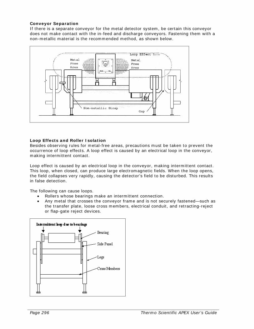
Page 296 Thermo Scientific APEX User’s Guide
Conveyor Separation If there is a separate conveyor for the metal detector system, be certain this conveyor does not make contact with the in-feed and discharge conveyors. Fastening them with a non-metallic material is the recommended method, as shown below.
Loop Effects and Roller Isolation Besides observing rules for metal-free areas, precautions must be taken to prevent the occurrence of loop effects. A loop effect is caused by an electrical loop in the conveyor, making intermittent contact. Loop effect is caused by an electrical loop in the conveyor, making intermittent contact. This loop, when closed, can produce large electromagnetic fields. When the loop opens, the field collapses very rapidly, causing the detector’s field to be disturbed. This results in false detection. The following can cause loops.
• Rollers whose bearings make an intermittent connection. • Any metal that crosses the conveyor frame and is not securely fastened—such as
the transfer plate, loose cross members, electrical conduit, and retracting-reject or flap-gate reject devices.
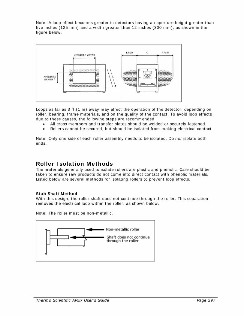
Thermo Scientific APEX User’s Guide Page 297
Note: A loop effect becomes greater in detectors having an aperture height greater than five inches (125 mm) and a width greater than 12 inches (300 mm), as shown in the figure below.
Loops as far as 3 ft (1 m) away may affect the operation of the detector, depending on roller, bearing, frame materials, and on the quality of the contact. To avoid loop effects due to these causes, the following steps are recommended.
• All cross members and transfer plates should be welded or securely fastened. • Rollers cannot be secured, but should be isolated from making electrical contact.
Note: Only one side of each roller assembly needs to be isolated. Do not isolate both ends.
Roller Isolation Methods The materials generally used to isolate rollers are plastic and phenolic. Care should be taken to ensure raw products do not come into direct contact with phenolic materials. Listed below are several methods for isolating rollers to prevent loop effects. Stub Shaft Method With this design, the roller shaft does not continue through the roller. This separation removes the electrical loop within the roller, as shown below. Note: The roller must be non-metallic.
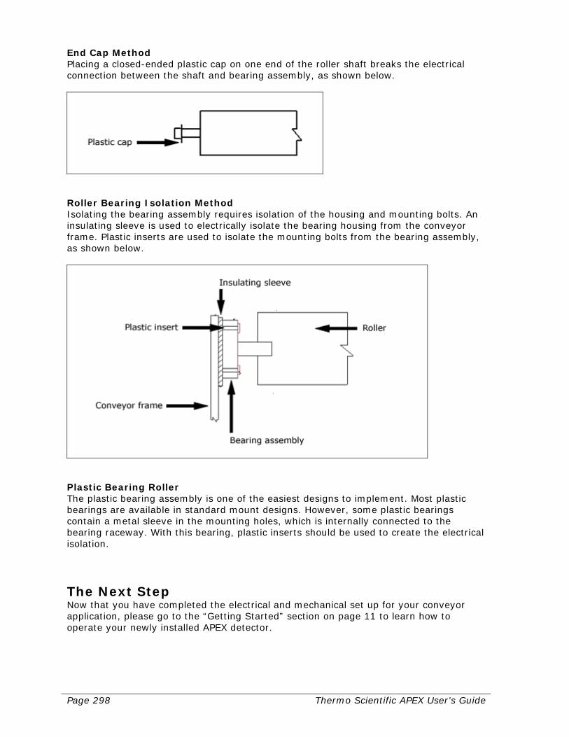
Page 298 Thermo Scientific APEX User’s Guide
End Cap Method Placing a closed-ended plastic cap on one end of the roller shaft breaks the electrical connection between the shaft and bearing assembly, as shown below.
Roller Bearing Isolation Method Isolating the bearing assembly requires isolation of the housing and mounting bolts. An insulating sleeve is used to electrically isolate the bearing housing from the conveyor frame. Plastic inserts are used to isolate the mounting bolts from the bearing assembly, as shown below.
Plastic Bearing Roller The plastic bearing assembly is one of the easiest designs to implement. Most plastic bearings are available in standard mount designs. However, some plastic bearings contain a metal sleeve in the mounting holes, which is internally connected to the bearing raceway. With this bearing, plastic inserts should be used to create the electrical isolation.
The Next Step Now that you have completed the electrical and mechanical set up for your conveyor application, please go to the “Getting Started” section on page 11 to learn how to operate your newly installed APEX detector.

Thermo Scientific APEX User’s Guide Page 299
Mechanical Set-Up for Gravity-Feed and Rx Applications The APEX detector is designed specifically for use in gravity-feed and pharmaceutical (Rx) applications. If this system was supplied complete, with a framework, non-metallic throughput tube, and automatic divert valve, it will require a minimal amount of installation and adjustment. When a search head only is provided, proper installation is critical. Correctly installed, the metal detector will operate reliably for long periods without attention. The customer is responsible for initial inspection of the equipment and site preparation. It is essential that the customer place the equipment in the production or process line, in accordance with the guidelines below. The customer must assure that qualified service personnel are available to make interconnections with other production equipment and perform work at the installation site. A Thermo Fisher Scientific Products Customer Service Representative is available to supervise installation and verify operation, as well as train personnel assigned to operate and maintain the equipment.
APEX Installation Considerations Customers who intend to install the APEX metal detector, should study the following factors that can influence the detector’s performance. The importance of studying this section and taking note of the information given is very important. It has been proven that faulty metal detector operation, such as random false alarm signals and undue sensitivity to vibration, are usually due to incorrect installation of the metal detector or some other factors external to the metal detector itself. Location of the Detector The APEX controls should be located to give easy access to the front panel. The installation location of the display and/or electronics box should be the first consideration. Mounting the APEX For trouble free and reliable operation, it is very important that the APEX be correctly mounted. The support structure for mounting the APEX must transmit a minimum amount of vibration to the metal detector. This structure must be flat and parallel, thereby minimizing possible twisting torques to the metal detector case which can distort the electromagnetic field and cause false triggering. While the APEX and the support structure may remain in contact, nothing including the product, must be allowed to touch any part of the aperture as this could cause wear of the aperture lining and give random false alarms. Any pressure, torque, or electrical ground will cause the APEX to misfire. Any support platform, or throughput pipe that passes through the aperture must be completely free of all metal and must not touch any part of the aperture at any time. Metal-Free Area For optimum performance, non-moving metal should be allowed no closer to the aperture opening than 1.5 times the smallest aperture height, measured outward from the center of the aperture. Moving metal should be allowed no closer to the aperture opening than 2.0 times the smallest aperture height, measured outward from the center
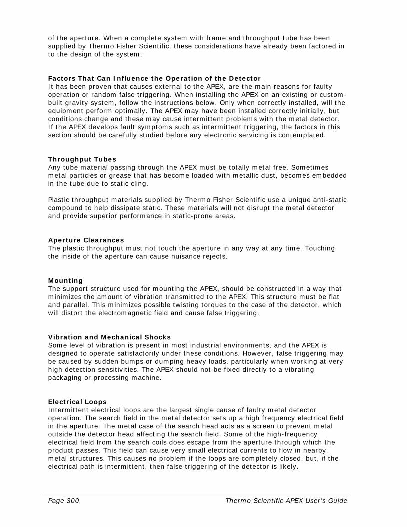
Page 300 Thermo Scientific APEX User’s Guide
of the aperture. When a complete system with frame and throughput tube has been supplied by Thermo Fisher Scientific, these considerations have already been factored in to the design of the system. Factors That Can Influence the Operation of the Detector It has been proven that causes external to the APEX, are the main reasons for faulty operation or random false triggering. When installing the APEX on an existing or custom-built gravity system, follow the instructions below. Only when correctly installed, will the equipment perform optimally. The APEX may have been installed correctly initially, but conditions change and these may cause intermittent problems with the metal detector. If the APEX develops fault symptoms such as intermittent triggering, the factors in this section should be carefully studied before any electronic servicing is contemplated. Throughput Tubes Any tube material passing through the APEX must be totally metal free. Sometimes metal particles or grease that has become loaded with metallic dust, becomes embedded in the tube due to static cling. Plastic throughput materials supplied by Thermo Fisher Scientific use a unique anti-static compound to help dissipate static. These materials will not disrupt the metal detector and provide superior performance in static-prone areas. Aperture Clearances The plastic throughput must not touch the aperture in any way at any time. Touching the inside of the aperture can cause nuisance rejects. Mounting The support structure used for mounting the APEX, should be constructed in a way that minimizes the amount of vibration transmitted to the APEX. This structure must be flat and parallel. This minimizes possible twisting torques to the case of the detector, which will distort the electromagnetic field and cause false triggering. Vibration and Mechanical Shocks Some level of vibration is present in most industrial environments, and the APEX is designed to operate satisfactorily under these conditions. However, false triggering may be caused by sudden bumps or dumping heavy loads, particularly when working at very high detection sensitivities. The APEX should not be fixed directly to a vibrating packaging or processing machine. Electrical Loops Intermittent electrical loops are the largest single cause of faulty metal detector operation. The search field in the metal detector sets up a high frequency electrical field in the aperture. The metal case of the search head acts as a screen to prevent metal outside the detector head affecting the search field. Some of the high-frequency electrical field from the search coils does escape from the aperture through which the product passes. This field can cause very small electrical currents to flow in nearby metal structures. This causes no problem if the loops are completely closed, but, if the electrical path is intermittent, then false triggering of the detector is likely.
Thermo Scientific APEX User’s Guide Page 301
Typical causes of intermittent electrical loops include loose bolts on the framework or on the detector’s mounting, corrosion of metal work, broken welds, open hinged doors, and broken or rubbing contacts. Interference can be overcome by opening the conductive path with an insulating pad or closing the path by welding or tightening the bolts so that it cannot become intermittent. The source of such loop interference can be very elusive and difficult to locate. The larger the aperture in the APEX, the greater the high-frequency leakage out of the aperture and the greater the possibility of trouble from loops. Metal Objects Near the Search Head The metal detector is very efficiently screened and metal near the top, bottom, and ends will not significantly affect the detector performance. However, metal positioned close to the aperture can cause interference problems, if it moves or vibrates. The area close to the aperture, which should be kept metal free, is known as the metal-free zone. This metal-free zone is dependent on the aperture dimensions and the sensitivity setting of the detector. The search head is sensitive to moving metal. It is not always possible to discriminate if the metal is passing through the head or moving outside the head. Metal in the metal-free zone may cause the detector to be sensitive to vibration. If the APEX vibrates or is accidentally bumped, it will cause relative movement between the detector and the offending metal, which could trigger the detector. Electrical Interference It is always good practice to suppress electrical interference at its source and, if trouble is experienced, the offending source should be located and suppressed. If this is not possible, it may be necessary to operate the APEX at a reduced sensitivity. A relay in the metal detector is often used to control solenoid valves, power contractors, and similar electrical devices. When these devices are switched off, the collapsing field of the winding generates a wide-band interference, which may be picked up by the search coils in the head and cause false triggering. A capacitor of suitable capacity and working voltage connected across the offending device and grounded as close to the device as possible, will often provide satisfactory suppression. Pneumatic Air Connect incoming air to the detector’s air-regulator fittings using a coiled copper tube or air hose. Adjust the incoming air pressure to 30–40 PSI (2.1–2.5 kg/cm2) for pneumatic devices, or 40–80 PSI (2.8–5.6 kg/cm2) for air rejects.
Page 302 Thermo Scientific APEX User’s Guide
Components of a Gravity-Feed Application The gravity-feed system must only be lifted and installed using the support frame. At no time must the metal detector be used for lifting. The ideal way to maneuver the equipment is to use support straps from the frame and lift into position. The frame must be bolted into position ensuring a good earth connection. The chute/pipe section may then be bolted in position. Care must be taken to avoid any weight or undo strains on the chute. A gravity-feed system consists of the following three major components.
• Search Head The search head contains the search-head board and the inspection coils the material passes through.
• Control Unit and Integral Power Supply The control unit contains the user interface controls, processing electronics, and should always be mounted remotely. The power supply unit, which houses power supplies, input/output devices and the connection terminal strip, should always be mounted remotely.
• Reject Valve and Support Structure The reject valve and support structure are used on gravity applications. The structure supports the metal detector; reject valve and product inspection tube. The control unit and power supply may be mounted directly to the structure.
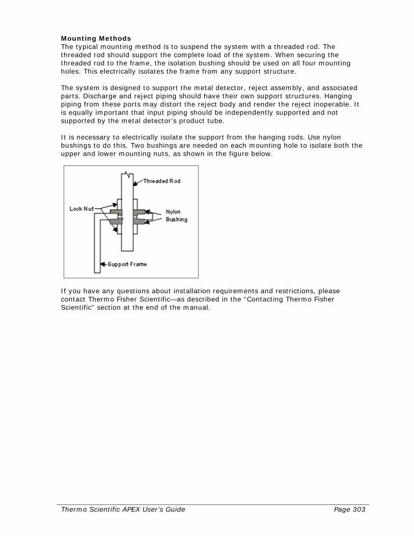
Thermo Scientific APEX User’s Guide Page 303
Mounting Methods The typical mounting method is to suspend the system with a threaded rod. The threaded rod should support the complete load of the system. When securing the threaded rod to the frame, the isolation bushing should be used on all four mounting holes. This electrically isolates the frame from any support structure. The system is designed to support the metal detector, reject assembly, and associated parts. Discharge and reject piping should have their own support structures. Hanging piping from these ports may distort the reject body and render the reject inoperable. It is equally important that input piping should be independently supported and not supported by the metal detector’s product tube. It is necessary to electrically isolate the support from the hanging rods. Use nylon bushings to do this. Two bushings are needed on each mounting hole to isolate both the upper and lower mounting nuts, as shown in the figure below.
If you have any questions about installation requirements and restrictions, please contact Thermo Fisher Scientific—as described in the “Contacting Thermo Fisher Scientific” section at the end of the manual.

Page 304 Thermo Scientific APEX User’s Guide
Testing a Gravity-Feed System When testing a gravity-feed system it is important to test both the sensitivity of the detector and the response of the reject valve. To accomplish this a metal test sample must be inserted at or near the zero velocity point of the product. Also a means for retrieving the test sample after it goes through the system should be incorporated in case the reject device fails to operate.
Test Procedures for Gravity-Feed and Rx Systems A complete and thorough test of the metal detector system must be done upon initial installation and whenever a major component of the system has been changed or altered. A complete check of the metal detector must include the reject device. Any test procedure designed for your application should take into account the following. Pass the Product Through the Detector’s Centerline The metal detector’s least sensitive point in the aperture is along the centerline of the opening. Any testing should be done so that the test sample passes approximately through the centerline of the opening. If the test sample is run at the side of the product tube or between the product tube and the detector, this will produce a larger signal than through the centerline.

Thermo Scientific APEX User’s Guide Page 305
Factors Affecting the Sensitivity of the Detector Sensitivity capabilities of different detectors used in different applications will vary. A smaller aperture is capable of detecting smaller pieces of metal. Product effect may also interfere with the detection capability. It is dangerous to rely on a corporate standard to determine and test the detector’s operation. Ideally, each detector should have its own standards of operation and a corporate outline should be used only as a maximum allowable guide. Sample sizes should be selected so that they are clearly detectable (peak signal size of approximately double the detect level), when compared to the signal produced by the product or other interfering signals. If samples are established which are very close to the product signal, frustration on the part of operators can lead to a lack of confidence in the detector’s operation. The detector should be tested at its normal operating speed. Test pieces should be inserted so that they travel through the detectors at the product’s normal rate of flow. This ensures that the detector and reject device responses are accurately tested. The detector is not equally sensitive to all types of metal. Depending on the type of product and application, there can be three typical metal groups, which will produce three different levels of detection, as follows.
• Ferrous—typically, any magnetic metal is the easiest to detect.
• Non-ferrous—any good electrical conducting metal such as aluminum, copper, brass, and so forth.
• Stainless steel—the 300-series stainless steels, which are non-magnetic, tend to be the most difficult metals to detect.
Test samples used should contain spherical metal contaminants. Any other shape will produce a different size signal depending on its orientation as it passes through the detector. This can lead to inconsistent results. In addition, any test procedure established must allow for the test product to be completely rejected by the reject device. The reject device will tend to be the most likely point of failure in any detector system. Care must be taken so that if the detector or reject device fails to operate correctly, the test sample can still be recovered. This can be achieved by the use of a second valve or a removable catch grid, which can operate as a fail-safe device, catching the test sample and allowing product to flow through. Contact Thermo Fisher Scientific for assistance—as described in the “Contacting Thermo Fisher Scientific” section at the end of the manual. Note: If insertion testing is difficult to achieve, “side of the pipe” method may be used for frequent sensitivity testing. Adjustment to the test sample size should be made to compensate for the increase in sensitivity of the metal detector as you near the side of the aperture. Under most circumstances the metal detection will be approximately 0.5 to 1.0 mm more sensitive as you reach the edge of the aperture. If this method is used it is highly recommended that you use reject confirmation to ensure the correct performance of the system. Testing Schedule The user must decide how often the detector should be tested. If the test procedure can be designed to be simple, it will help ensure that the test will be performed more

Page 306 Thermo Scientific APEX User’s Guide
frequently. As a guide it must be decided how much product would have to be put on hold for re-inspection, if a detector fails the test. Typically the minimum frequency is once per shift, while other applications require hourly tests be performed. Rejected Product Examination If possible, product, which has been rejected by the detector during production, should be examined to establish the source and type of contamination. This may lead to an improvement in the process equipment upstream from the detector. It is also useful to display these contaminants so that all employees can see the benefit of the metal detector. Tube Size Use the following formula to calculate the approximate duct/chute dimensions for the system. In2 = Flow Rate (lbs/hr) x 0.024 Bulk Density (lbs/ft3) Choose the duct/chute size so the product fills no more than 80% of the product tube. Here is an example. If the product to be inspected has a bulk density of 30 lbs/cubic ft, and a flow rate of 15,000 lbs/hr, the result would be 12 square inches. With 80% fill, the chute should be sized to 15 square inches. The dimensions of the metal detector should be kept to the smallest size possible for the best sensitivity. It is then a matter of choosing a product tube with the same square inches that is best suited for the application. In the above example you could use a chute dimension as follows.
• 127 mm (5") x 76 mm (3").
• 203 mm (8") x 51 mm (2"), or 129 mm (4.75") diameter. By choosing the 203 mm (8") x 51 mm (2") chute there will be a smaller stroke on the reject valve and a faster reaction time. The metal detector will be approximately 25 mm (1") larger on both the length and width (rounded up to the next available size), giving an aperture of 250 mm (9.8") x 75 mm (3"). If the product is prone to bridging, the 127 mm (5") x 76 mm (3") or 120 mm (4.75") diameter units would be preferable. Contact Thermo Fisher Scientific—as described in the “Contacting Thermo Fisher Scientific” section at the end of the manual—for further assistance.
The Next Step Now that you have completed the electrical and mechanical set up for your gravity-feed application, please go to the “Getting Started” section on page 11 to learn how to operate your newly installed APEX detector.
Thermo Scientific APEX User’s Guide Page 307
Mechanical Set-Up for Pipeline Applications The APEX detector is designed specifically for use in a pipeline application. If this system was supplied complete with a framework, non-metallic throughput tube, and automatic divert valve, it will require a minimal amount of adjustment. When a search head only is provided, proper installation is critical. Correctly installed, the metal detector will operate reliably for long periods without attention. The customer is responsible for initial inspection of the equipment and site preparation. It is essential that the customer place the equipment in the production or process line in accordance with the guidelines below. The customer must assure that qualified service personnel are available to make interconnections with other production equipment and perform work at the installation site. A Thermo Fisher Scientific Products Customer Service Representative is available to supervise installation and verify operation, as well as train personnel assigned to operate and maintain the equipment.
APEX Installation Considerations Customers who intend to install the APEX metal detector, should study the following factors that can influence the detector’s performance. The importance of studying this section and taking note of the information given is very important. It has been proven that faulty metal detector operation, such as random false alarm signals and undue sensitivity to vibration, are usually due to incorrect installation of the metal detector or some other factors external to the metal detector itself. Location of the Detector The APEX controls should be located to give easy access to the front panel. The installation location of the display and/or electronics box should be the first consideration. Mounting the APEX For trouble-free and reliable operation, it is very important that the APEX be correctly mounted. The support structure for mounting the APEX must transmit a minimum amount of vibration to the metal detector. This structure must be flat and parallel, thereby minimizing possible twisting torques to the metal detector case, which can distort the electromagnetic field and cause false triggering. While the APEX and the support structure may remain in contact, nothing, including the product, must be allowed to touch any part of the aperture, as this could cause wear of the aperture lining and give random false alarms. Any pressure, torque, or electrical ground will cause the APEX to misfire. Any support platform, or throughput pipe that passes through the aperture must be completely free of all metal, and must not touch any part of the aperture at any time. Metal-Free Area For optimum performance, non-moving metal should be allowed no closer to the aperture opening than 1.5 times the smallest aperture height, measured outward from the center of the aperture. Moving metal should be allowed no closer to the aperture opening than 2.0 times the smallest aperture height, measured outward from the center

Page 308 Thermo Scientific APEX User’s Guide
of the aperture. When a complete system with frame and throughput tube has been supplied by Thermo Fisher Scientific, these considerations have already been factored in to the design of the system. Factors That Can Influence the Operation of the Detector It has been proven that causes external to the APEX, are the main reasons for faulty operation or random false triggering. When installing the APEX on an existing or custom-built pipeline system, the instructions below should be carefully studied. Only when correctly installed will the equipment perform optimally. The APEX may have been installed correctly initially, but conditions change that may cause intermittent problems with the metal detector. If the APEX develops fault symptoms such as intermittent triggering, the factors in this section should be carefully studied before any electronic servicing is contemplated. Throughput Tubes Any tube material passing through the APEX must be totally metal free. Sometimes metal particles or grease that has become loaded with metallic dust, becomes embedded in the tube. Aperture Clearances The plastic throughput must not touch the aperture in any way at any time. Touching the inside of the aperture can cause nuisance rejects. Mounting The support structure used for mounting the APEX, should be constructed in a way that minimizes the amount of vibration transmitted to the APEX. This structure must be flat and parallel. This minimizes possible twisting torques to the case of the detector, which will distort the electromagnetic field and cause false triggering. Vibration and Mechanical Shocks Some level of vibration is present in most industrial environments and the APEX is designed to operate satisfactorily under these conditions. However, false triggering may be caused by sudden bumps or dumping of heavy loads nearby, particularly when working at very high detection sensitivities. The APEX should not be fixed directly to a vibrating packaging or processing machine. Electrical Loops Intermittent electrical loops are the largest single cause of faulty metal detector operation. The search field in the metal detector sets up a high-frequency electrical field in the aperture. The metal case of the detector head acts as a screen to prevent metal outside the detector head affecting the search field. Some of the high-frequency electrical field from the search coils does escape from the aperture through which the product passes. This field can cause very small electrical currents to flow in nearby metal structures. This causes no problem if the loops are completely closed, but, if the electrical path is intermittent, then false triggering of the detector is likely. Typical causes of intermittent electrical loops include loose bolts on the framework or on the detector’s mounting, corrosion of metal work, broken welds, open hinged doors, and broken or rubbing contacts.
Thermo Scientific APEX User’s Guide Page 309
Interference can be overcome by opening the conductive path with an insulating pad or closing the path by welding or tightening the bolts so that it cannot become intermittent. The source of such loop interference can be very elusive and difficult to locate. The larger the aperture in the APEX, the greater the high-frequency leakage out of the aperture and the greater the possibility of trouble from loops. Metal Objects Near the Search Head The metal detector is very efficiently screened and metal near the top, bottom, and ends will not significantly affect the detector performance. However, metal positioned close to the aperture can cause interference problems, if it moves or vibrates. The area close to the aperture which should be kept metal free is known as the metal-free zone. This metal-free zone is dependent upon the aperture dimensions and the sensitivity setting of the detector. The metal detector is sensitive to moving metal. It is not always possible to discriminate if the metal is passing through the head or moving outside the head. Metal in the metal-free zone may cause the detector to be sensitive to vibration. If the APEX vibrates or is accidentally bumped, it will cause relative movement between the detector and the offending metal, which could trigger the detector. Electrical Interference It is always good practice to suppress electrical interference at its source and, if trouble is experienced, the offending source should be located and suppressed. If this is not possible, it may be necessary to operate the APEX at a reduced sensitivity. A relay in the metal detector is often used to control solenoid valves, power contractors, and similar electrical devices. When these devices are switched off, the collapsing field of the winding generates a wide-band interference, which may be picked up by the search coils in the detector head and cause false triggering. A capacitor of suitable capacity and working voltage connected across the offending device and grounded as close to the device as possible, will often provide satisfactory suppression. Pneumatic Air Connect incoming air to the detector’s air-regulator fittings using a coiled copper tube or air hose. Adjust the incoming air pressure to 30–40 PSI (2.1–2.5 kg/cm2) for pneumatic devices, or 40–80 PSI (2.8–5.6 kg/cm2) for air rejects.
The Next Step Now that you have completed the electrical and mechanical set up for your pipeline application, please go to the “Getting Started” section on page 11 to learn how to operate your newly installed APEX detector.

Page 310 Thermo Scientific APEX User’s Guide

Thermo Scientific APEX User’s Guide Page 311
Safety and Warranty Information Please read this section carefully, because it contains important safety and warranty information for which you are responsible.
Software License This document is confidential and is the property of Thermo Fisher Scientific Inc. It may not be copied or reproduced in any way without the express written consent of Thermo Fisher Scientific. This document also is an unpublished work of Thermo Fisher Scientific. Thermo Fisher Scientific intends to, and is maintaining the work as confidential information. Thermo Fisher Scientific also may seek to protect this work as an unpublished copyright. In the event of either inadvertent or deliberate publication, Thermo Fisher Scientific intends to enforce its rights to this work under the copyright laws as a published work. Those having access to this work may not copy, use, or disclose the information in this work unless expressly authorized by Thermo Fisher Scientific. “Microsoft” and “Windows” are either registered trademarks or trademarks of Microsoft Corporation in the United States and/or other countries. All other trademarks are the property of Thermo Fisher Scientific Inc. and its subsidiaries. Terms of the Software License The software program is licensed, not sold. Thermo Fisher Scientific Inc. grants you a license for the software program only in the country where you acquired the equipment, as defined below. You obtain no rights other than those granted you under this license. The term “equipment” means the equipment with which the software program is used. The term “software program” means the original and all whole or partial copies of the software program used in connection with equipment sold by Thermo Fisher Scientific to the user, including modified copies or portions of the software program. Thermo Fisher Scientific retains title to the software program, as well as all improvements, modifications and enhancements to the software program, whether made by Thermo Fisher Scientific or any other party. Thermo Fisher Scientific owns, or has licensed from the owner, copyrights in the software program. You are responsible for the selection of the equipment. Following the commissioning of the equipment, any change made by the user to the software program will terminate all warranties with respect to the equipment and software program. All other trademarks are the property of Thermo Fisher Scientific Inc. and its subsidiaries.

Page 312 Thermo Scientific APEX User’s Guide
Allowed Uses Under the License Under this license, you may do the following. Use the software program on only one piece of equipment at any one time, unless the license information specifies otherwise. Copy the software program for backup or in order to modify it. Modify the software program and/or merge it into another software program. Subject to the following limitations, transfer the possession of the software program to another party, but only in connection with a transfer of the equipment. If you transfer the software program, you must transfer a copy of these license terms, all other documentation and at least one complete, unaltered copy of the software program to the other party. Unless you have other copies of the software program to be used in connection with other equipment purchased from Thermo Fisher Scientific, or one of its divisions, you must, at the same time, either transfer all your other copies of the software program to the transferee of the equipment or destroy them. Your license is then terminated. The other party agrees to these terms and conditions by its first use of the software program. You must reproduce the copyright notices(s) on each copy of the software program. You may not do the following. Use, copy, modify, merge, or transfer copies of the software program except as provided in this license. Reverse engineer, decompile, or disassemble the software program. Sub-license, rent, lease, or assign the software program. Limitation of Remedies Thermo Fisher Scientific’s liability under this license is as follows. Thermo Fisher Scientific will: (a) replace defective media, or (b) make a warranted software program operate or (c) replace the software program with a functionally equivalent software program, as warranted. For any claim (including breach), in any form, related in any way to this license, Thermo Fisher Scientific’s liability will be for the actual value of the software program. Thermo Fisher Scientific will not be liable for any lost profits, lost savings, any incidental damages, or other economic consequential damages, even if Thermo Fisher Scientific, or its authorized supplier, has been advised of the possibility of such damages. Thermo Fisher Scientific will not be liable for any damages claimed by you based on any third party claim. General Conditions of the License Thermo Fisher Scientific may terminate your license if you fail to comply with the terms and conditions of this license. In such event, you must destroy all your copies of the
Thermo Scientific APEX User’s Guide Page 313
software program. You are responsible for payment of any taxes, including personal property taxes, resulting from this license.
Using the APEX in USA and Europe Please note the following. Occupational Safety and Health Act (OSHA) The Occupational Safety and Health Act clearly places the burden of compliance on the user of the equipment and the act is generalized to the extent that determination of compliance is a judgment decision on the part of the local inspection. Hence, Thermo Fisher Scientific will not be responsible for meeting the full requirements of OSHA in respect to the equipment supplied or for any penalty assessed for failure to meet the requirements, in respect to the equipment supplied, as interpreted by an authorized inspector. Thermo Fisher Scientific will use their best efforts to remedy such violation at a reasonable cost to the buyer. European Directives Thermo Fisher Scientific products sold in Europe are compliant with European Directives relating to CE marking and all heads or systems (head, product transport, and rejecting mechanisms) are labeled in accordance with the directives. Product labeling is affixed securely, visible to the user, and contains the following information. Warnings of any residual risk (nip points, reject mechanisms, inside PSU areas). Name and address of Thermo Fisher Scientific. Year of manufacture. Product type. Serial number. Supply voltage and frequency. Maximum rated current. Identification of the protective earth terminal. CE mark on machines. Other Certifications The APEX is designed to operate in all parts of the world and, as such, is marked with a label bearing CE and cCSAus marks. In addition, the APEX is designed to be used in atmospheres where combustible dust may sometimes be present. An explanation is given on the marking label. The APEX is designed to operate in a Zone 22 hazardous area and complies with the following standards.
• IEC 61242 Electrical Apparatus for Use in the Presence of Combustible Dust— Part 0 (General Requirements)
• IEC 61241 Electrical Apparatus for Use in the Presence of Combustible Dust— Part 1 (Protection by Enclosures “tD”)
Page 314 Thermo Scientific APEX User’s Guide
Important Safety Notices about Using the APEX Please note carefully the following safety warnings and notices. Intended Uses for the Detector Your metal detector is intended to be used in food, pharmaceutical, and other applications where the presence of metal contaminants is undesirable. It must not be used for any other purpose. Your metal detector runs automatically and does not require constant operator presence. During calibration, the operator’s presence will be required for up to five minutes typically. He/she will manually feed calibrated metal test sticks onto the product transport mechanism and verify that reject mechanisms associated with the installation operate successfully. Product transport mechanisms are usually located at waist height, as are reject mechanisms and user controls. We recommend to customers that metal detector systems be sited within their premises conveniently for setting up and calibration. Safety in Transportation and Handling Metal detector heads and systems form an integral part of your plant and when transporting, handling, and installing the unit, your own plant safety instructions must be applied. Because your metal detector and systems are tailored to application requirements, it is impossible to be precise about product mass/weight. If precise values are required, the shipping crate will be marked with the overall shipping mass of the product and this may be used as a reasonable guideline. Ensuring User Safety Metal detector systems are usually incorporated into a customer product line. If the metal detection system is fitted with product guards, there may be mechanical hazards present. The customer must ensure that upstream or downstream areas do not allow access to the mechanical hazards. Typically, some reject mechanisms are powerful and could cause non-minor damage to personnel if guarding is not in place. Because the reject mechanism is usually at the downstream end of the equipment, the customer must ensure that sufficient guards are fitted downstream to prevent operator access into these areas. Safe Practices During Use, Maintenance, and Repair This manual contains details as appropriate including the appropriate tools. However, because of its importance, the warning contained in the maintenance section is repeated here. TO GUARANTEE PERSONAL SAFETY, CARE MUST BE TAKEN WHEN WORKING ON OR AROUND CONVEYORS, REJECT MECHANISMS, OR PRODUCT TUBES. AS WITH ALL SUCH DEVICES THE MAIN SUPPLIES (ELECTRICAL AND AIR) TO THE SYSTEM MUST BE LOCKED OFF WHEN PERFORMING REPAIR OR MAINTENANCE WORK. AFTER DISCONNECTING THE AIR SUPPLY TO THE SYSTEM, CYCLE ANY REJECT MECHANISMS TO EVACUATE ANY AIR LEFT IN THE SYSTEM. THEN SWITCH OFF AND LOCK THE ELECTRICAL SUPPLY. Safe Disposal of the Detector See Safety in Transportation, Handling and Installation for procedures. There are no hazardous materials used on the metal detector head or system.

Thermo Scientific APEX User’s Guide Page 315
Training Needs of Users We offer all customers full training for operations and maintenance staff.
Electrical Safety of the Detector Please note the following. Earth Ground For more information, see page 286. Supply-Voltage Requirements and Connections For more information, see pages 285 and 288. Other Wiring During Installation For more information, see page 284. Electro-Magnetic Environment Loss of sensitivity and false rejecting can occur under the following conditions. Your metal detector is located close to equipment using variable speed controllers or high frequency heating equipment. Your metal detector is located close to another metal detector operating at similar frequencies. Walkie-talkie, hand-held or radio frequency devices are operated close to the metal detector. Loss of sensitivity may go unnoticed due to radio-frequency (RF) signal “swamping” the input circuits. If there is any doubt, check calibration of the search head under these circumstances. For assistance in finding solutions to your EM problems, contact Thermo Fisher Scientific—as described in the “Contacting Thermo Fisher Scientific” section at the end of the manual. Low Voltage Directives All of the recommendations for EMC apply to the prevention of electrical shock. If access to the PSU area is required, the incoming AC power supply should be isolated remotely and locked-off. Access to the PSU area by untrained personnel is not recommended. Circuit Breaker The APEX should be permanently connected to its AC supply. Please ensure that when installing the APEX, a switch or circuit breaker is used and is positioned close to the metal detector in easy reach of the operator. The switch or circuit breaker shall be marked as the disconnecting device for the metal detector. DO NOT install the APEX in a position that makes it hard to use the AC mains isolator.
Page 316 Thermo Scientific APEX User’s Guide
Thermo Fisher Scientific Warranty The seller agrees, represents, and warrants that the equipment delivered hereunder shall be free from defects in material and workmanship. Such warranty shall not apply to accessories, parts, or material purchased by the seller unless they are manufactured pursuant to seller's design, but shall apply to the workmanship incorporated in the installation of such items in the complete equipment. To the extent, purchased parts or accessories are covered by the manufacturer's warranty; seller shall extend such warranty to buyer. Seller's obligation under said warranty is conditioned upon the return of the defective equipment, transportation charges prepaid, to the seller's factory in Minneapolis, Minnesota, and the submission of reasonable proof to seller prior to return of the equipment that the defect is due to a matter embraced within seller's warranty hereunder. Any such defect in material and workmanship shall be presented to seller as soon as such alleged errors or defects are discovered by purchaser and seller is given opportunity to investigate and correct alleged errors or defects and in all cases, buyer must have notified seller thereof within one (1) year after delivery, or one (1) year after installation if the installation was accomplished by the seller. Said warranty shall not apply if the equipment shall not have been operated and maintained in accordance with seller's written instructions applicable to such equipment, or if such equipment shall have been repaired or altered or modified without seller's approval; provided, however, that the foregoing limitation of warranty insofar as it relates to repairs, alterations, or modifications, shall not be applicable to routine preventive and corrective maintenance which normally occur in the operation of the equipment. “EXCEPT FOR THOSE WARRANTIES SPECIFICALLY CONTAINED HEREIN, SELLER DISCLAIMS ANY AND ALL WARRANTIES WITH RESPECT TO THE EQUIPMENT DELIVERED HEREUNDER, INCLUDING THE IMPLIED WARRANTIES OF MERCHANTABILITY AND FITNESS FOR USE. THE SOLE LIABILITY OF SELLER ARISING OUT OF THE WARRANTY CONTAINED HEREIN SHALL BE EXCLUSIVELY LIMITED TO BREACH OF THOSE WARRANTIES. THE SOLE AND EXCLUSIVE REMEDY FOR BREACH OF THE WARRANTIES SET OUT ABOVE SHALL BE LIMITED TO THE REPAIR OR REPLACEMENT OF ANY DEFECTIVE ACCESSORY, PART OR MATERIAL WITH A SIMILAR ITEM FREE FROM DEFECT, AND THE CORRECTION OF ANY DEFECT IN WORKMANSHIP. IN NO EVENT SHALL SELLER BE LIABLE FOR ANY INCIDENTAL OR CONSEQUENTIAL DAMAGES.” Purchaser agrees to underwrite the cost of any labor required for replacement; including time, travel, and living expenses of a Thermo Fisher Scientific Field Service Engineer at the closest factory base. Thermo Fisher Scientific 501 90th Avenue NW Minneapolis, MN 55433 Phone: (800) 227-8891 Fax: (763) 783-2525

Thermo Scientific APEX User’s Guide Page 317
Disclaimer Though the information provided herein is believed to be accurate, be advised that the information contained herein is not a guarantee for satisfactory results. Specifically, this information is neither a warranty nor guarantee, expressed or implied, regarding performance, merchantability, fitness, or any other matter with respect to the products, and recommendation for use of the product/process information in conflict with any patent. Please note that Thermo Fisher Scientific reserves the right to change and/or improve the product design and specifications without notice.
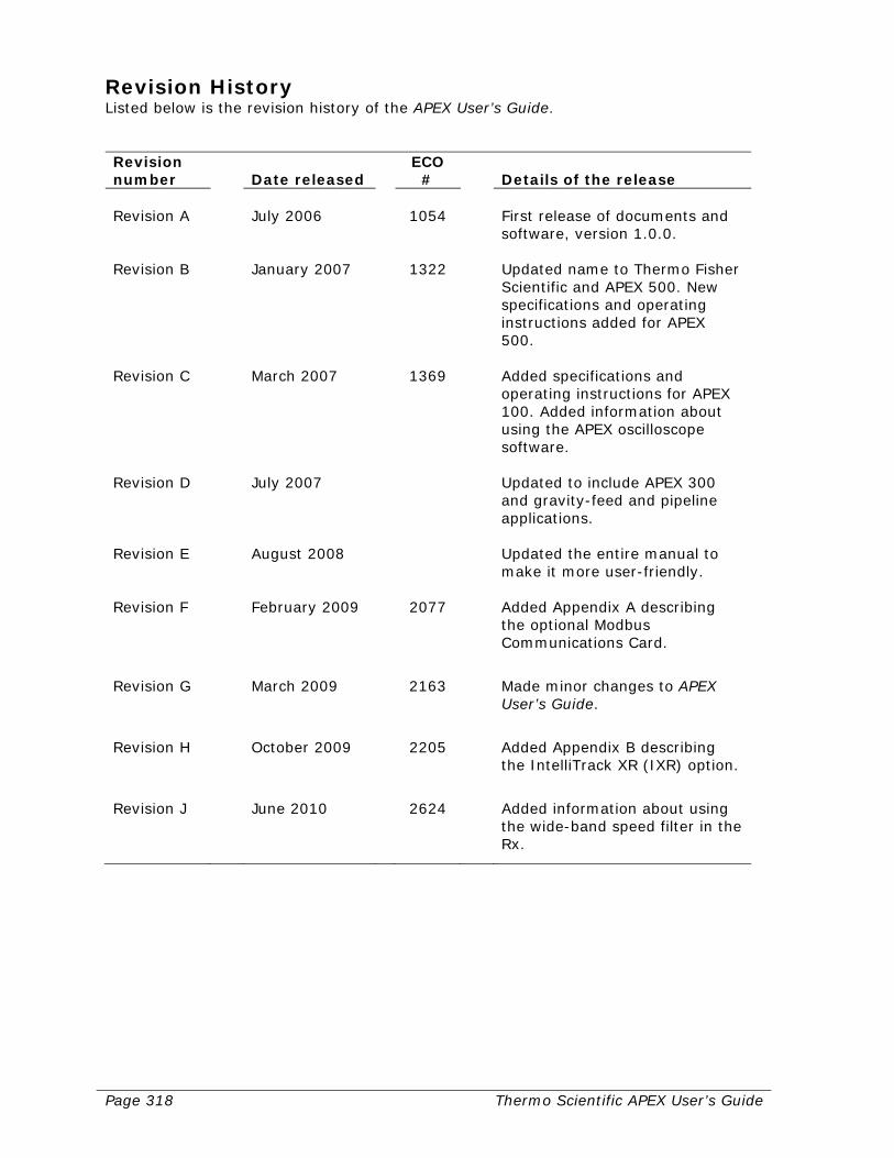
Page 318 Thermo Scientific APEX User’s Guide
Revision History Listed below is the revision history of the APEX User’s Guide. Revision number
Date released
ECO #
Details of the release
Revision A July 2006 1054 First release of documents and
software, version 1.0.0. Revision B January 2007 1322 Updated name to Thermo Fisher
Scientific and APEX 500. New specifications and operating instructions added for APEX 500.
Revision C March 2007 1369 Added specifications and
operating instructions for APEX 100. Added information about using the APEX oscilloscope software.
Revision D July 2007 Updated to include APEX 300
and gravity-feed and pipeline applications.
Revision E August 2008 Updated the entire manual to
make it more user-friendly. Revision F February 2009 2077 Added Appendix A describing
the optional Modbus Communications Card.
Revision G March 2009 2163 Made minor changes to APEX User’s Guide.
Revision H October 2009 2205 Added Appendix B describing the IntelliTrack XR (IXR) option.
Revision J June 2010 2624 Added information about using the wide-band speed filter in the Rx.

Thermo Scientific APEX User’s Guide Page 319
Appendix A—Modbus Communications Card

Page 320 Thermo Scientific APEX User’s Guide
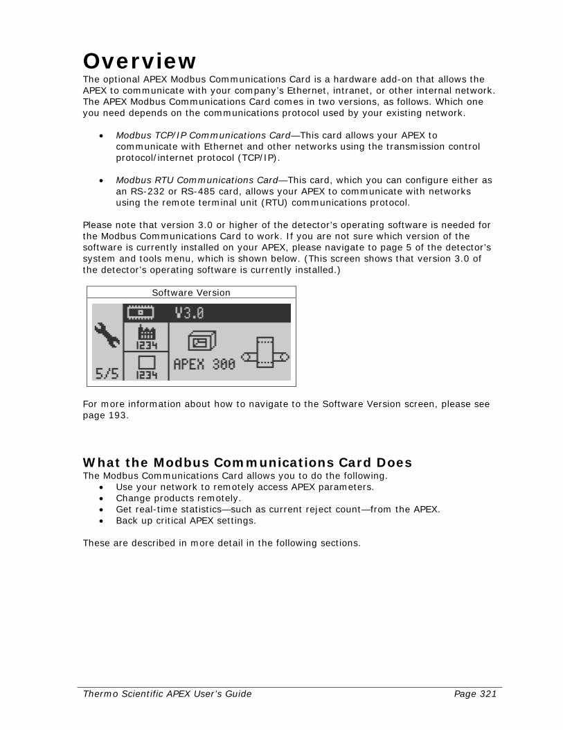
Thermo Scientific APEX User’s Guide Page 321
Overview The optional APEX Modbus Communications Card is a hardware add-on that allows the APEX to communicate with your company’s Ethernet, intranet, or other internal network. The APEX Modbus Communications Card comes in two versions, as follows. Which one you need depends on the communications protocol used by your existing network.
• Modbus TCP/IP Communications Card—This card allows your APEX to communicate with Ethernet and other networks using the transmission control protocol/internet protocol (TCP/IP).
• Modbus RTU Communications Card—This card, which you can configure either as
an RS-232 or RS-485 card, allows your APEX to communicate with networks using the remote terminal unit (RTU) communications protocol.
Please note that version 3.0 or higher of the detector’s operating software is needed for the Modbus Communications Card to work. If you are not sure which version of the software is currently installed on your APEX, please navigate to page 5 of the detector’s system and tools menu, which is shown below. (This screen shows that version 3.0 of the detector’s operating software is currently installed.)
Software Version
For more information about how to navigate to the Software Version screen, please see page 193.
What the Modbus Communications Card Does The Modbus Communications Card allows you to do the following.
• Use your network to remotely access APEX parameters. • Change products remotely. • Get real-time statistics—such as current reject count—from the APEX. • Back up critical APEX settings.
These are described in more detail in the following sections.
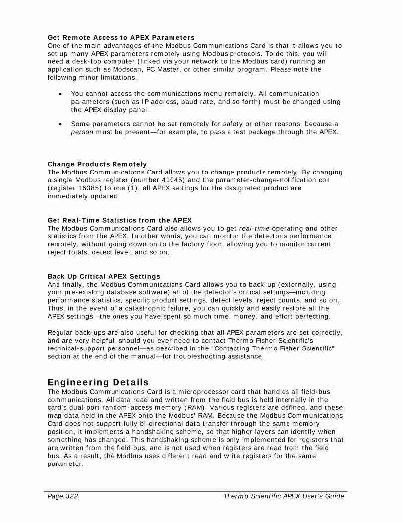
Page 322 Thermo Scientific APEX User’s Guide
Get Remote Access to APEX Parameters One of the main advantages of the Modbus Communications Card is that it allows you to set up many APEX parameters remotely using Modbus protocols. To do this, you will need a desk-top computer (linked via your network to the Modbus card) running an application such as Modscan, PC Master, or other similar program. Please note the following minor limitations.
• You cannot access the communications menu remotely. All communication parameters (such as IP address, baud rate, and so forth) must be changed using the APEX display panel.
• Some parameters cannot be set remotely for safety or other reasons, because a
person must be present—for example, to pass a test package through the APEX. Change Products Remotely The Modbus Communications Card allows you to change products remotely. By changing a single Modbus register (number 41045) and the parameter-change-notification coil (register 16385) to one (1), all APEX settings for the designated product are immediately updated. Get Real-Time Statistics from the APEX The Modbus Communications Card also allows you to get real-time operating and other statistics from the APEX. In other words, you can monitor the detector’s performance remotely, without going down on to the factory floor, allowing you to monitor current reject totals, detect level, and so on. Back Up Critical APEX Settings And finally, the Modbus Communications Card allows you to back-up (externally, using your pre-existing database software) all of the detector’s critical settings—including performance statistics, specific product settings, detect levels, reject counts, and so on. Thus, in the event of a catastrophic failure, you can quickly and easily restore all the APEX settings—the ones you have spent so much time, money, and effort perfecting. Regular back-ups are also useful for checking that all APEX parameters are set correctly, and are very helpful, should you ever need to contact Thermo Fisher Scientific’s technical-support personnel—as described in the “Contacting Thermo Fisher Scientific” section at the end of the manual—for troubleshooting assistance.
Engineering Details The Modbus Communications Card is a microprocessor card that handles all field-bus communications. All data read and written from the field bus is held internally in the card’s dual-port random-access memory (RAM). Various registers are defined, and these map data held in the APEX onto the Modbus’ RAM. Because the Modbus Communications Card does not support fully bi-directional data transfer through the same memory position, it implements a handshaking scheme, so that higher layers can identify when something has changed. This handshaking scheme is only implemented for registers that are written from the field bus, and is not used when registers are read from the field bus. As a result, the Modbus uses different read and write registers for the same parameter.

Thermo Scientific APEX User’s Guide Page 323
Expert Knowledge Is Required to Modify Settings As a general rule, only engineers, programmers, and others who have extensive experience managing network communication parameters and registers should attempt to change any configurations described in this appendix. If you are not sure what you are doing, please contact Thermo Fisher Scientific—as described in the “Contacting Thermo Fisher Scientific” section at the end of the manual. In addition, having a list of current Modbus register values, is very helpful, when contacting Thermo Fisher Scientific.
Overview of the Installation Process This appendix assumes that a Thermo Fisher Scientific technician has already done the following to get the communication functions of the Modbus up and running.
• Installed the appropriate (TCP/IP or RTU) Modbus Communications Card and made the appropriate hardware configurations (by setting the card’s DIP switches to the correct positions).
• Installed version 3.0 or higher of the detector’s operating software in your APEX metal detector.
• Set up (“configured”) the appropriate communication parameters (using the APEX software) so that the APEX is recognized by your network.
Modifying the Modbus Settings Clearly, if you want to upgrade from an RTU to a TCP/IP network (or vice versa), you will have to purchase a new Modbus Communications Card. However, if you are currently using an RTU Communications Card that has been configured as an RS-232 device, and want to upgrade its capabilities to an RS485 device (or vice versa), all you have to do is change one of the DIP switches on your existing card (as described in the appropriate RS-232 or RS-485 section of the “Configuring the Modbus hardware” section of this appendix). Most other configuration changes for both a TCP/IP and RTU Communications Card are made using the APEX operating software, specifically by accessing the Modbus configuration menu. These are described in detail in the “Configuring Network Parameters with the APEX Software” section of this appendix. If you have questions or need additional help, please contact Thermo Fisher Scientific—as described in the “Contacting Thermo Fisher Scientific” section at the end of the manual.

Page 324 Thermo Scientific APEX User’s Guide

Thermo Scientific APEX User’s Guide Page 325
Configuring Network Parameters with the APEX Software This section tells you how to use the detector’s built-in operating software to configure your network using the detector’s communications menu and functions. This section—please note—does not tell you how to reconfigure the hardware settings for your Modbus Communications Card. This is covered in the “Configuring the Modbus Hardware” section on page 341. Please verify which type of Modbus Communications Card is installed in your APEX, and make sure that it matches the type of network (TCP/IP or RTU) are configuring. Then go to the appropriate section for detailed instructions about configuring your particular type of network.
• For a TCP/IP network, go to the next section (below). • For an RTU network, see the instructions on page 335.
Configuring a TCP/IP Network This section tells you how to use the APEX software to modify the communication parameters for a TCP/IP network. You can set the following parameters using the APEX communications menu.
• Dynamic host-control protocol (on or off) • IP address • Subnet-mask address • Gateway address

Page 326 Thermo Scientific APEX User’s Guide
Accessing the TCP/IP Communications Menu To access the detector’s TCP/IP communications menu, do the following. 1) Make sure the detector’s Main Menu is displayed.
Product Name
2) Navigate to the system and tools menu.
System and Tools
3) Press the Go button and page 1 of the system and tools menu appears.
System and Tools Page 1
4) Navigate to page 2 of the system and tools menu.
System and Tools Page 2
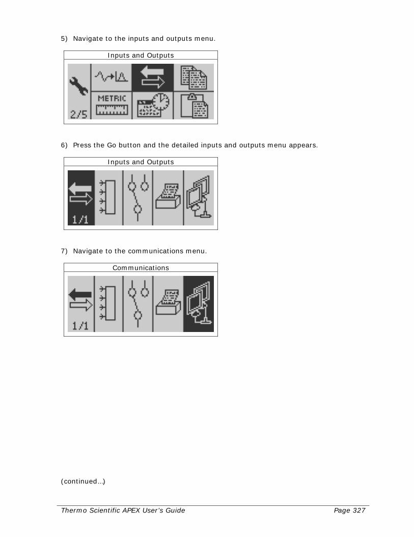
Thermo Scientific APEX User’s Guide Page 327
5) Navigate to the inputs and outputs menu.
Inputs and Outputs
6) Press the Go button and the detailed inputs and outputs menu appears.
Inputs and Outputs
7) Navigate to the communications menu.
Communications
(continued…)
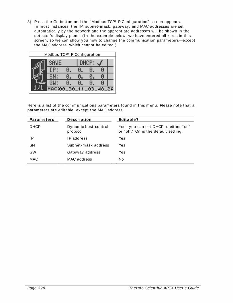
Page 328 Thermo Scientific APEX User’s Guide
8) Press the Go button and the “Modbus TCP/IP Configuration” screen appears. In most instances, the IP, subnet-mask, gateway, and MAC addresses are set automatically by the network and the appropriate addresses will be shown in the detector’s display panel. (In the example below, we have entered all zeros in this screen, so we can show you how to change the communication parameters—except the MAC address, which cannot be edited.)
Modbus TCP/IP Configuration
Here is a list of the communications parameters found in this menu. Please note that all parameters are editable, except the MAC address. Parameters Description Editable?
DHCP Dynamic host-control protocol
Yes—you can set DHCP to either “on” or “off.” On is the default setting.
IP IP address Yes
SN Subnet-mask address Yes
GW Gateway address Yes
MAC MAC address No

Thermo Scientific APEX User’s Guide Page 329
Changing the DHCP Default Setting During Installation The default setting for DHCP is “on” (as shown by the check mark next to the function). Because the DHCP setting is set—by default—to “on,” a network host-device will set the IP, subnet-mask, gateway, and MAC addresses for you when you do either of the following.
• Scenario 1—Powering up the APEX for the first time after installing the Modbus
card. • Scenario 2—Powering down the APEX (for example, by turning it off at night) and
powering it up again (for example, by restarting the APEX in the morning). It is scenario 2 that sometimes causes a problem, because the network may assign new addresses to the APEX, leading to network problems. Thus, if you constantly power down and power up the APEX, it is best to let the network assign the addresses when you first install the Modbus card (scenario 1), and then change the DHCP setting to “off” to lock in these addresses. Then, during subsequent power ups and downs (scenario 2), a network device cannot change these addresses, eliminating potential network problems for the APEX.
Changing DHCP to “Off” To change the DHCP setting to “off” (and lock in your current IP, subnet-mask, and gateway addresses), do the following. 1) Make sure the DHCP function is highlighted. (The check mark indicates that DHCP is
currently set to its default value, “on.”)
Dynamic Host Control Protocol
(continued…)

Page 330 Thermo Scientific APEX User’s Guide
2) Press the Go button. The check mark changes to an X, indicating that DHCP is now “off.” (The flashing asterisk tells you the DHCP setting has been modified.)
Dynamic Host Control Protocol
3) Press the Back button to exit the function.
Manually Changing Communication Parameters If you wish to manually change the IP, subnet-mask, and gateway addresses, please note the following.
• The DHCP setting must be set to “off.” • For your changes to take effect, you must save your settings.
How to change the IP, subnet-mask, and gateway addresses as well as save your TCP/IP settings, is described in the following sections.
Changing the IP Address In order to change the IP address, DHCP must be set to “off.” 1) Make sure the IP address function is highlighted.
IP Address
(continued…)
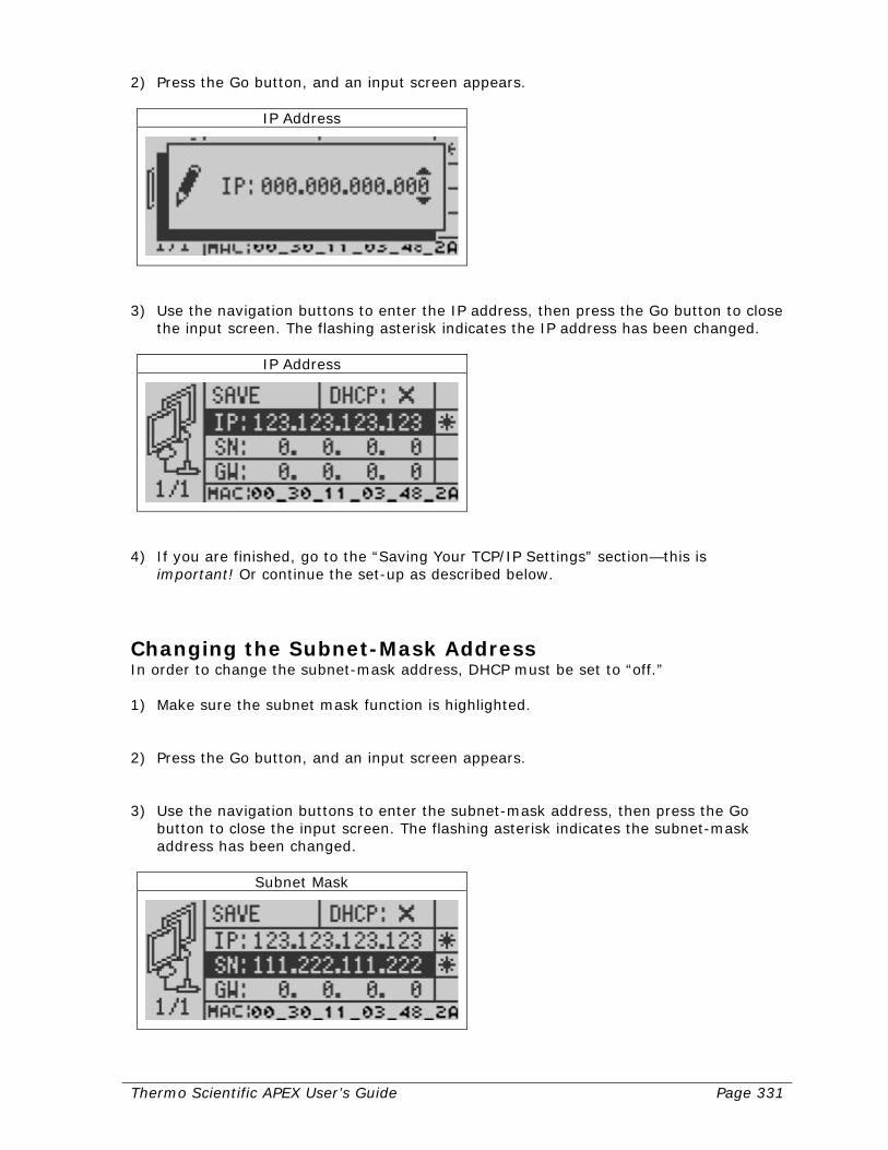
Thermo Scientific APEX User’s Guide Page 331
2) Press the Go button, and an input screen appears.
IP Address
3) Use the navigation buttons to enter the IP address, then press the Go button to close
the input screen. The flashing asterisk indicates the IP address has been changed.
IP Address
4) If you are finished, go to the “Saving Your TCP/IP Settings” section—this is
important! Or continue the set-up as described below.
Changing the Subnet-Mask Address In order to change the subnet-mask address, DHCP must be set to “off.” 1) Make sure the subnet mask function is highlighted. 2) Press the Go button, and an input screen appears. 3) Use the navigation buttons to enter the subnet-mask address, then press the Go
button to close the input screen. The flashing asterisk indicates the subnet-mask address has been changed.
Subnet Mask

Page 332 Thermo Scientific APEX User’s Guide
4) If you are finished, go to the “Saving Your TCP/IP Settings” section—this is important! Or continue the set-up as described below.
Changing the Gateway Address In order to change the gateway address, DHCP must be set to “off.” 1) Make sure the gateway function is highlighted. 2) Press the Go button, and an input screen appears. 3) Use the navigation buttons to enter the gateway address, then press the Go button
to close the input screen. The flashing asterisk indicates the gateway address has been changed.
Default Gateway Address
4) Go to the “Saving Your TCP/IP Settings” section—this is important!
MAC Addresses Please note that the MAC address cannot be changed using the APEX software, because it is set directly by the hardware.
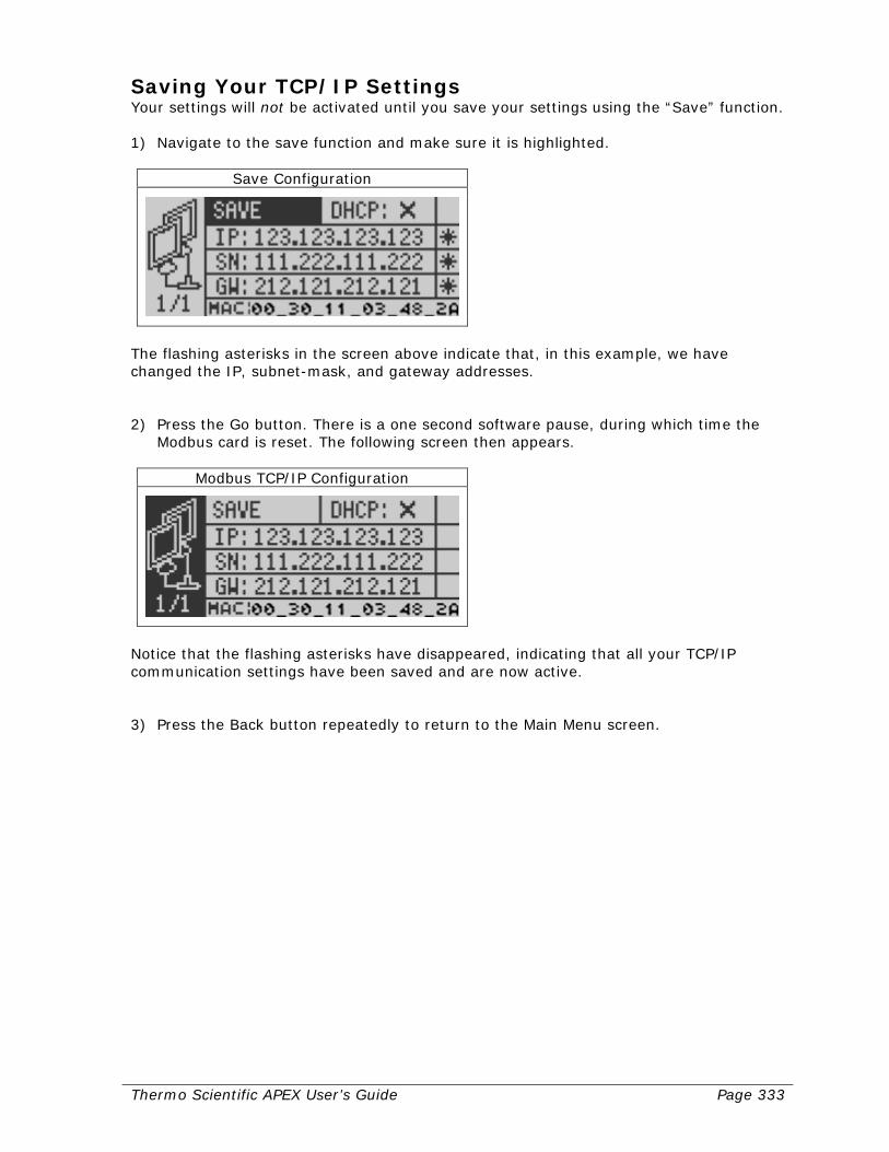
Thermo Scientific APEX User’s Guide Page 333
Saving Your TCP/IP Settings Your settings will not be activated until you save your settings using the “Save” function. 1) Navigate to the save function and make sure it is highlighted.
Save Configuration
The flashing asterisks in the screen above indicate that, in this example, we have changed the IP, subnet-mask, and gateway addresses. 2) Press the Go button. There is a one second software pause, during which time the
Modbus card is reset. The following screen then appears.
Modbus TCP/IP Configuration
Notice that the flashing asterisks have disappeared, indicating that all your TCP/IP communication settings have been saved and are now active. 3) Press the Back button repeatedly to return to the Main Menu screen.
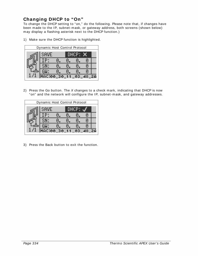
Page 334 Thermo Scientific APEX User’s Guide
Changing DHCP to “On” To change the DHCP setting to “on,” do the following. Please note that, if changes have been made to the IP, subnet-mask, or gateway address, both screens (shown below) may display a flashing asterisk next to the DHCP function.) 1) Make sure the DHCP function is highlighted.
Dynamic Host Control Protocol
2) Press the Go button. The X changes to a check mark, indicating that DHCP is now
“on” and the network will configure the IP, subnet-mask, and gateway addresses.
Dynamic Host Control Protocol
3) Press the Back button to exit the function.
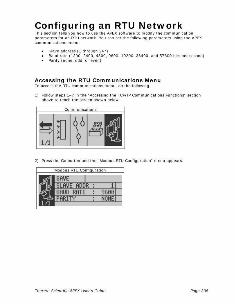
Thermo Scientific APEX User’s Guide Page 335
Configuring an RTU Network This section tells you how to use the APEX software to modify the communication parameters for an RTU network. You can set the following parameters using the APEX communications menu.
• Slave address (1 through 247) • Baud rate (1200, 2400, 4800, 9600, 19200, 38400, and 57600 bits per second) • Parity (none, odd, or even)
Accessing the RTU Communications Menu To access the RTU communications menu, do the following. 1) Follow steps 1–7 in the “Accessing the TCP/IP Communications Functions” section
above to reach the screen shown below.
Communications
2) Press the Go button and the “Modbus RTU Configuration” menu appears.
Modbus RTU Configuration

Page 336 Thermo Scientific APEX User’s Guide
Changing the Slave Address To change the slave address, do the following. 1) In the “Modbus RTU Configuration” screen, highlight the slave-address function.
Slave Address
2) Press the Go button and the following input screen appears.
Slave Address
3) Enter the slave address using the navigation buttons. (We entered 007 as the new
slave address.) 4) Press the Go button. The flashing asterisk tells you the slave address has been
changed.
Slave Address
5) If you are finished, go to the “Saving Your RTU Settings” section—this is important!
Or continue the set-up as described below.
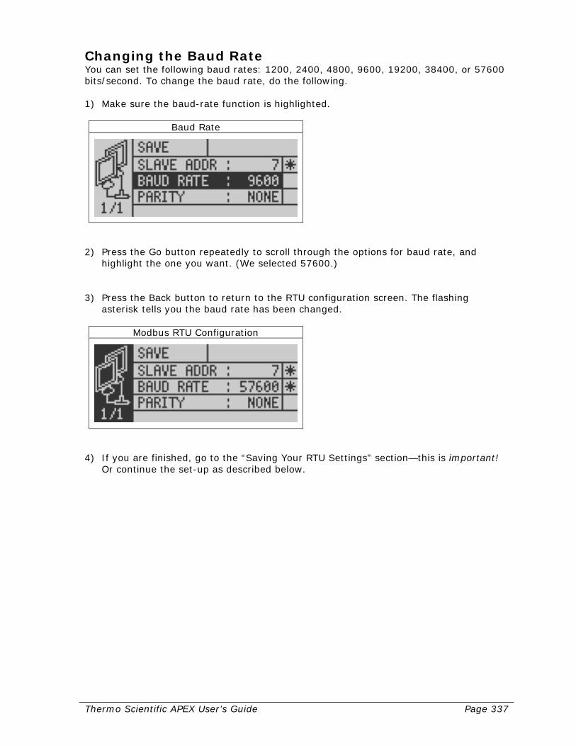
Thermo Scientific APEX User’s Guide Page 337
Changing the Baud Rate You can set the following baud rates: 1200, 2400, 4800, 9600, 19200, 38400, or 57600 bits/second. To change the baud rate, do the following. 1) Make sure the baud-rate function is highlighted.
Baud Rate
2) Press the Go button repeatedly to scroll through the options for baud rate, and
highlight the one you want. (We selected 57600.) 3) Press the Back button to return to the RTU configuration screen. The flashing
asterisk tells you the baud rate has been changed.
Modbus RTU Configuration
4) If you are finished, go to the “Saving Your RTU Settings” section—this is important!
Or continue the set-up as described below.
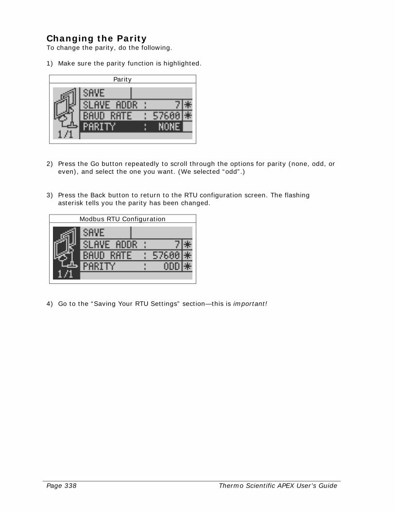
Page 338 Thermo Scientific APEX User’s Guide
Changing the Parity To change the parity, do the following. 1) Make sure the parity function is highlighted.
Parity
2) Press the Go button repeatedly to scroll through the options for parity (none, odd, or
even), and select the one you want. (We selected “odd”.) 3) Press the Back button to return to the RTU configuration screen. The flashing
asterisk tells you the parity has been changed.
Modbus RTU Configuration
4) Go to the “Saving Your RTU Settings” section—this is important!
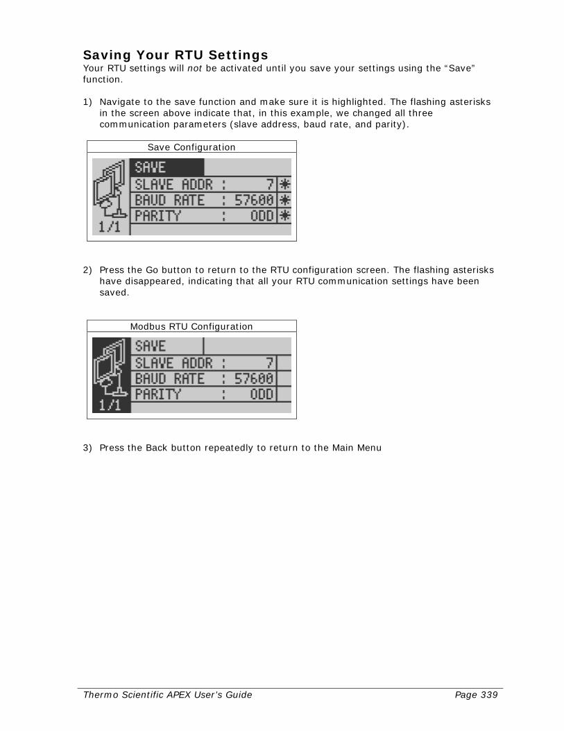
Thermo Scientific APEX User’s Guide Page 339
Saving Your RTU Settings Your RTU settings will not be activated until you save your settings using the “Save” function. 1) Navigate to the save function and make sure it is highlighted. The flashing asterisks
in the screen above indicate that, in this example, we changed all three communication parameters (slave address, baud rate, and parity).
Save Configuration
2) Press the Go button to return to the RTU configuration screen. The flashing asterisks
have disappeared, indicating that all your RTU communication settings have been saved.
Modbus RTU Configuration
3) Press the Back button repeatedly to return to the Main Menu

Page 340 Thermo Scientific APEX User’s Guide
Thermo Scientific APEX User’s Guide Page 341
Configuring the Modbus Hardware This section tells you how to configure (and install) the Modbus Communications Card. Please go to the appropriate section for detailed instructions.
• Modbus TCP/IP Communications Card—Go to the following section (page 342). • Modbus RTU Communications Card that you want to configure as an
RS-485 device—Go to page 345. • Modbus RTU Communications Card that you want to configure as an
RS-232 device—Go to page 349.

Page 342 Thermo Scientific APEX User’s Guide
Configuring the TCP/IP Card This section tells you how to install and configure your TCP/IP Modbus Communications Card, and how to interpret the four status LEDs on the card.
Card Schematic For most applications, here are the relevant parts of the Modbus TCP/IP Communications Card.
Installing the TCP/IP Card To mount your TCP/IP card on the APEX motherboard, do the following. 1) On the APEX motherboard, remove the HMI CPU (human-machine interface, central
processing unit) card. 2) Install the TCP/IP card on the APEX motherboard by connecting the card’s application
connector to the detector’s COMMS1 connector. Use the APEX Communication Module Mounting Kit to secure the card to the APEX motherboard.
3) Reinstall the HMI CPU on the motherboard.

Thermo Scientific APEX User’s Guide Page 343
Setting the Configuration Switches All switches should be set to the zero or “off” position, which allows you to configure all of the card’s communications parameters, except the MAC address, using the APEX software.
Pin Assignments for the Ethernet (RJ45) Connector Here are the pin assignments for the Ethernet (RJ45) connector. Pin Signal Notes
1 TD+ 2 TD– 3 RD+ 4 Normally left unused. To insure signal integrity, these pins are tied
together and terminated to the PE via a filter circuit in the module. 5 6 RD– 7 Normally left unused. To insure signal integrity, these pins are tied
together and terminated to the PE via a filter circuit in the module. 8
(Front view)
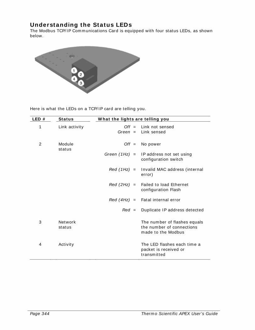
Page 344 Thermo Scientific APEX User’s Guide
Understanding the Status LEDs The Modbus TCP/IP Communications Card is equipped with four status LEDs, as shown below.
Here is what the LEDs on a TCP/IP card are telling you. LED # Status What the lights are telling you
1 Link activity Off = Green =
Link not sensed Link sensed
2 Module
status Off =
Green (1Hz) =
Red (1Hz) =
Red (2Hz) =
Red (4Hz) =
Red =
No power IP address not set using configuration switch Invalid MAC address (internal error) Failed to load Ethernet configuration Flash Fatal internal error Duplicate IP address detected
3 Network
status The number of flashes equals
the number of connections made to the Modbus
4 Activity The LED flashes each time a
packet is received or transmitted

Thermo Scientific APEX User’s Guide Page 345
Configuring the RTU RS-485 Card This section tells you how to install and configure your RTU RS-485 Modbus Communi-cations Card, and how to interpret the four status LEDs on the card. Please note that your particular card will be equipped with either a DB-9 connector or a screw connector.
Card Schematic For most applications, here are the relevant parts of the Modbus RS-485 card. (The figure shows an RS-485 card equipped with a DB-9 connector.)
Installing the Card To mount your RS-485 card on the APEX motherboard, do the following. 1) On the APEX motherboard, remove the HMI CPU (human-machine interface, central
processing unit) card. 2) Install the RS-485 card on the APEX motherboard by connecting the card’s
application connector to the detector’s COMMS1 connector. Use the APEX Communication Module Mounting Kit to secure the card to the APEX motherboard.
3) Reinstall the HMI CPU on the motherboard.
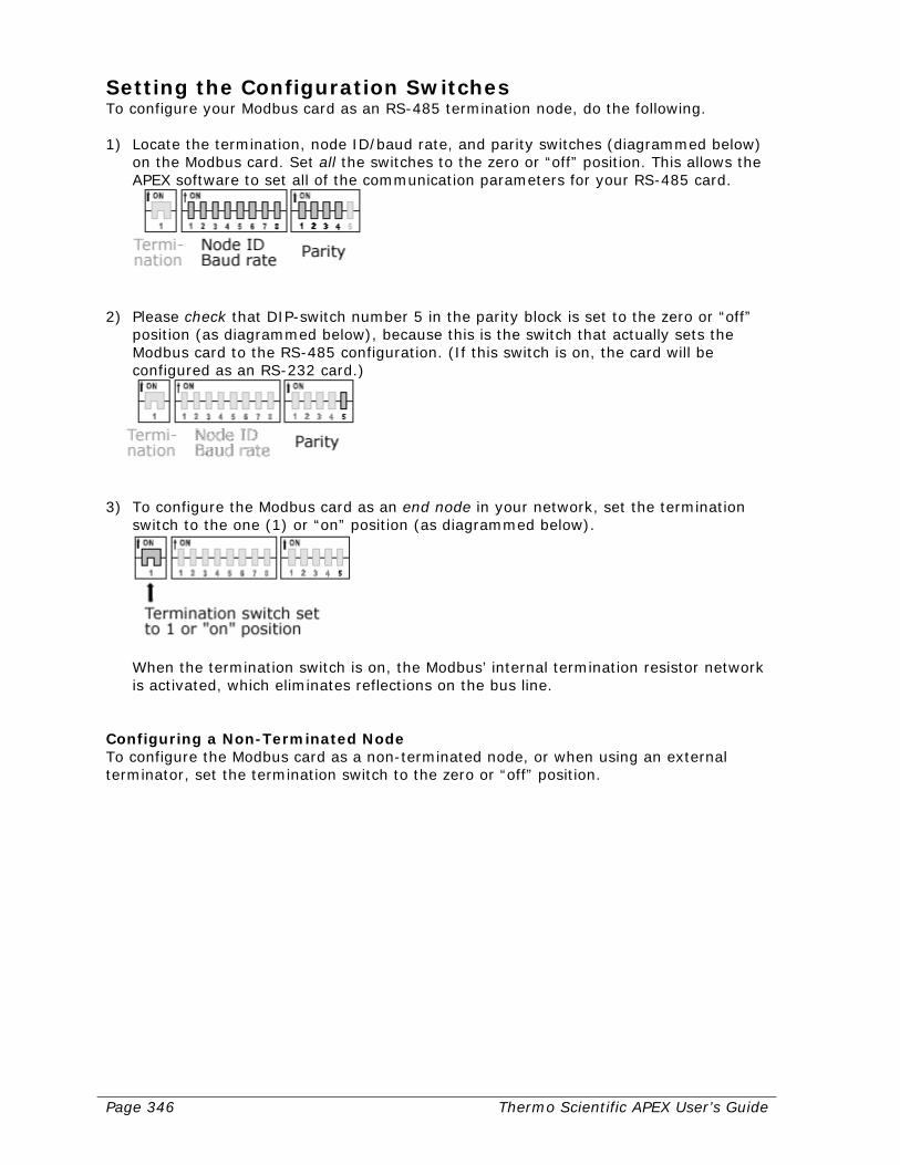
Page 346 Thermo Scientific APEX User’s Guide
Setting the Configuration Switches To configure your Modbus card as an RS-485 termination node, do the following. 1) Locate the termination, node ID/baud rate, and parity switches (diagrammed below)
on the Modbus card. Set all the switches to the zero or “off” position. This allows the APEX software to set all of the communication parameters for your RS-485 card.
2) Please check that DIP-switch number 5 in the parity block is set to the zero or “off”
position (as diagrammed below), because this is the switch that actually sets the Modbus card to the RS-485 configuration. (If this switch is on, the card will be configured as an RS-232 card.)
3) To configure the Modbus card as an end node in your network, set the termination
switch to the one (1) or “on” position (as diagrammed below).
When the termination switch is on, the Modbus’ internal termination resistor network is activated, which eliminates reflections on the bus line.
Configuring a Non-Terminated Node To configure the Modbus card as a non-terminated node, or when using an external terminator, set the termination switch to the zero or “off” position.
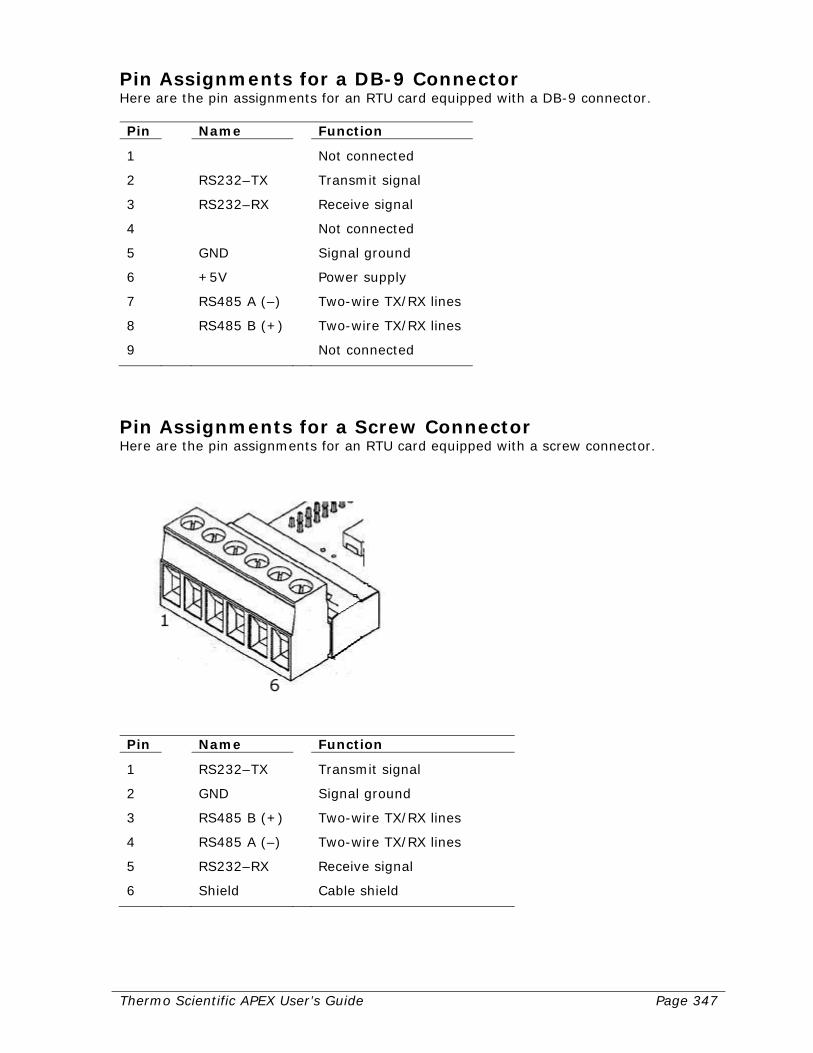
Thermo Scientific APEX User’s Guide Page 347
Pin Assignments for a DB-9 Connector Here are the pin assignments for an RTU card equipped with a DB-9 connector. Pin Name Function
1 Not connected
2 RS232–TX Transmit signal
3 RS232–RX Receive signal
4 Not connected
5 GND Signal ground
6 +5V Power supply
7 RS485 A (–) Two-wire TX/RX lines
8 RS485 B (+) Two-wire TX/RX lines
9 Not connected
Pin Assignments for a Screw Connector Here are the pin assignments for an RTU card equipped with a screw connector.
Pin Name Function
1 RS232–TX Transmit signal
2 GND Signal ground
3 RS485 B (+) Two-wire TX/RX lines
4 RS485 A (–) Two-wire TX/RX lines
5 RS232–RX Receive signal
6 Shield Cable shield
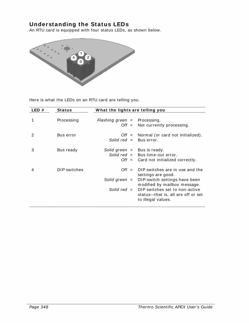
Page 348 Thermo Scientific APEX User’s Guide
Understanding the Status LEDs An RTU card is equipped with four status LEDs, as shown below.
Here is what the LEDs on an RTU card are telling you. LED # Status What the lights are telling you 1 Processing Flashing green =
Off = Processing. Not currently processing.
2 Bus error Off =
Solid red = Normal (or card not initialized). Bus error.
3 Bus ready Solid green =
Solid red = Off =
Bus is ready. Bus time-out error. Card not initialized correctly.
4 DIP switches Off =
Solid green =
Solid red =
DIP switches are in use and the settings are good. DIP-switch settings have been modified by mailbox message. DIP switches set to non-active status—that is, all are off or set to illegal values.

Thermo Scientific APEX User’s Guide Page 349
Configuring the RTU RS-232 Card This section tells you how to install and configure your RS-232 Modbus Communications Card, and how to interpret the four status LEDs on the card.
Installing the Card To mount your RS-232 card on the APEX motherboard, do the following. 1) On the APEX motherboard, remove the HMI CPU (human-machine interface, central
processing unit) card. 2) Install the RS-232 card on the APEX motherboard by connecting the card’s
application connector to the detector’s COMMS1 connector. Use the APEX Communication Module Mounting Kit to secure the card to the APEX motherboard.
3) Reinstall the HMI CPU on the motherboard.
Setting the Configuration Switches To configure your Modbus card as an RS-232 termination node, do the following. 1) Locate the termination, node ID/baud rate, and parity switches (diagrammed below)
on the Modbus card. Set all the switches to the zero or “off” position.
2) Set DIP-switch number 5 in the parity block to the one (1) or “on” position (as
diagrammed below), because this is the switch that actually sets the Modbus card to the RS-232 configuration. (If this switch is off, the card will be configured as an RS-485 card.)

Page 350 Thermo Scientific APEX User’s Guide
Pin Assignments for a DB-9 Connector See the RS-485 section, because the pin assignments are identical.
Pin Assignments for a Screw Connector See the RS-485 section, because the pin assignments are identical.
Understanding the Status LEDs See the RTU RS-485, because the way the LEDs operate is identical.
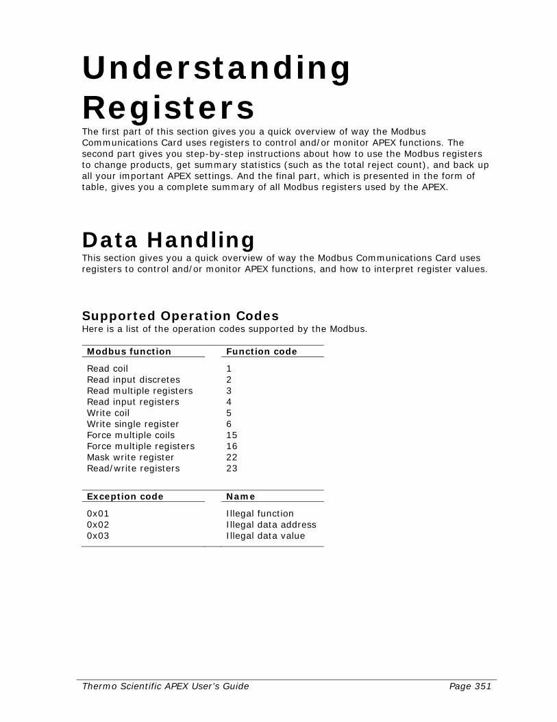
Thermo Scientific APEX User’s Guide Page 351
Understanding Registers The first part of this section gives you a quick overview of way the Modbus Communications Card uses registers to control and/or monitor APEX functions. The second part gives you step-by-step instructions about how to use the Modbus registers to change products, get summary statistics (such as the total reject count), and back up all your important APEX settings. And the final part, which is presented in the form of table, gives you a complete summary of all Modbus registers used by the APEX.
Data Handling This section gives you a quick overview of way the Modbus Communications Card uses registers to control and/or monitor APEX functions, and how to interpret register values.
Supported Operation Codes Here is a list of the operation codes supported by the Modbus. Modbus function Function code
Read coil 1 Read input discretes 2 Read multiple registers 3 Read input registers 4 Write coil 5 Write single register 6 Force multiple coils 15 Force multiple registers 16 Mask write register 22 Read/write registers 23
Exception code Name
0x01 Illegal function 0x02 Illegal data address 0x03 Illegal data value

Page 352 Thermo Scientific APEX User’s Guide
Read Data When the master wants to read a parameter, it simply reads the appropriate register or registers. Using the standard commands of the Modbus TCP, it is possible to read all the data of the table.
Write Data Each parameter that can be modified by the master, has two control bits to perform the handshaking operation, which are implemented as coils. These two control bits are named as follows. Control bit Description
Parameter-change notification Used to notify the APEX that the master has modified a parameter.
Parameter-change acknowledge Used to acknowledge that the APEX has
processed the parameter change.
If the master wants to change a parameter, it first updates the appropriate registers and then notifies the APEX by toggling the corresponding “parameter-change notification” coil. When the APEX has processed this change, it toggles the corresponding “parameter-change acknowledge” coil to signal that the parameter change has been processed. If the parameter written by the master is outside the range of acceptable values, then the APEX will not use it and will continue to use the previous value. In this case the Read and Write registers will contain different values, but the Read register will always contain the current value being used by the APEX. Note that the “parameter-change acknowledge” coil will still be toggled, indicating that the APEX has processed it.
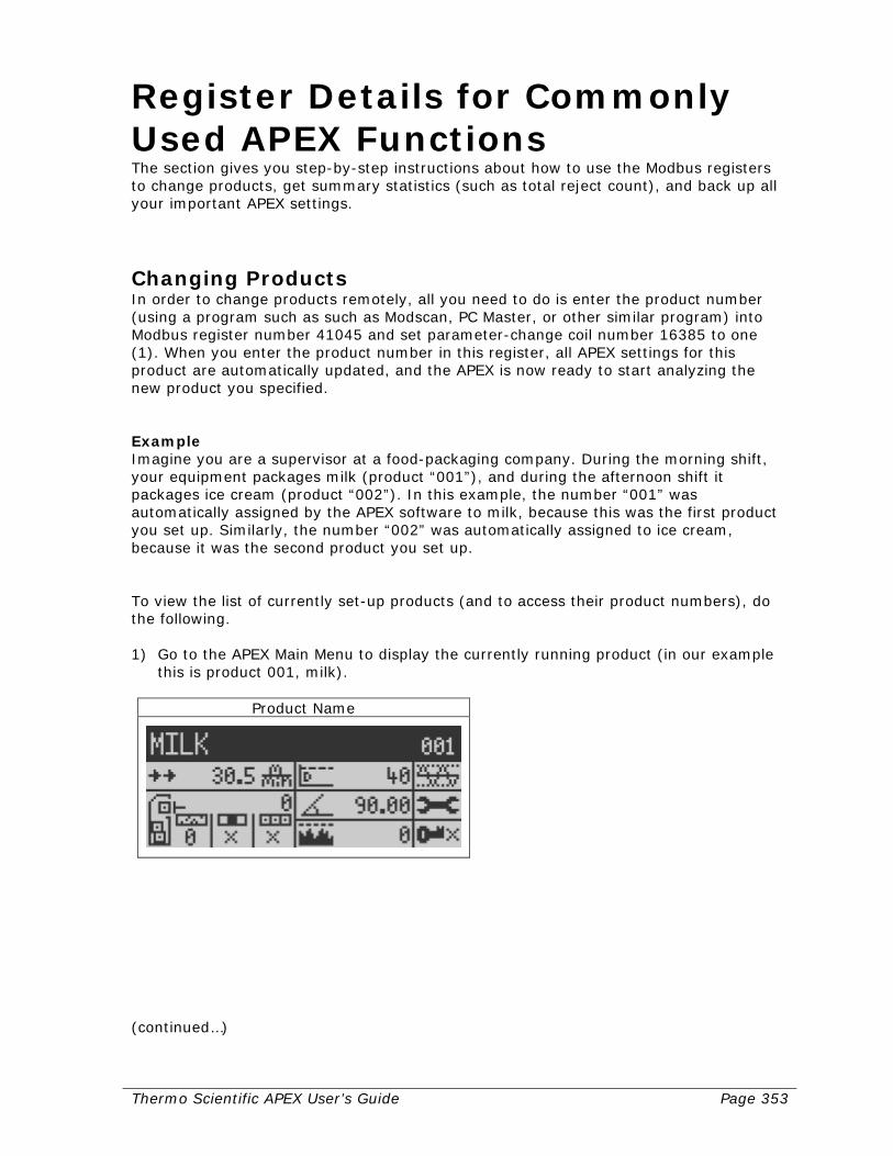
Thermo Scientific APEX User’s Guide Page 353
Register Details for Commonly Used APEX Functions The section gives you step-by-step instructions about how to use the Modbus registers to change products, get summary statistics (such as total reject count), and back up all your important APEX settings.
Changing Products In order to change products remotely, all you need to do is enter the product number (using a program such as such as Modscan, PC Master, or other similar program) into Modbus register number 41045 and set parameter-change coil number 16385 to one (1). When you enter the product number in this register, all APEX settings for this product are automatically updated, and the APEX is now ready to start analyzing the new product you specified. Example Imagine you are a supervisor at a food-packaging company. During the morning shift, your equipment packages milk (product “001”), and during the afternoon shift it packages ice cream (product “002”). In this example, the number “001” was automatically assigned by the APEX software to milk, because this was the first product you set up. Similarly, the number “002” was automatically assigned to ice cream, because it was the second product you set up. To view the list of currently set-up products (and to access their product numbers), do the following. 1) Go to the APEX Main Menu to display the currently running product (in our example
this is product 001, milk).
Product Name
(continued…)
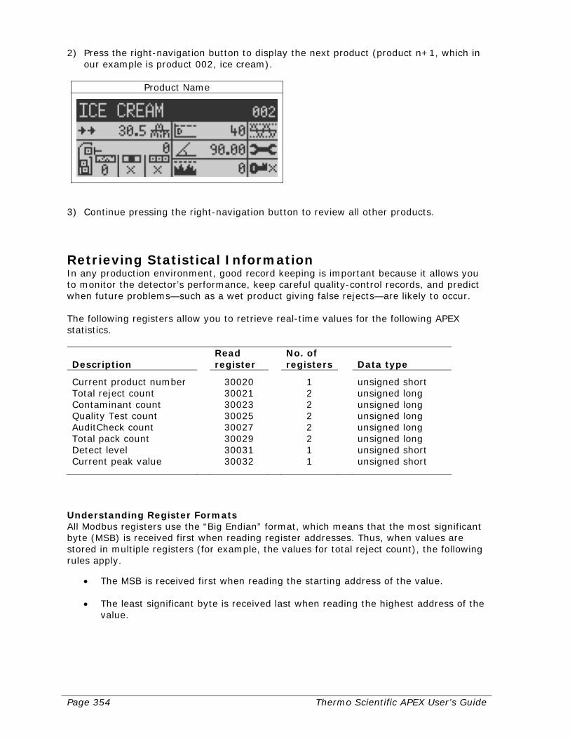
Page 354 Thermo Scientific APEX User’s Guide
2) Press the right-navigation button to display the next product (product n+1, which in our example is product 002, ice cream).
Product Name
3) Continue pressing the right-navigation button to review all other products.
Retrieving Statistical Information In any production environment, good record keeping is important because it allows you to monitor the detector’s performance, keep careful quality-control records, and predict when future problems—such as a wet product giving false rejects—are likely to occur. The following registers allow you to retrieve real-time values for the following APEX statistics. Description
Read register
No. of registers
Data type
Current product number 30020 1 unsigned short Total reject count 30021 2 unsigned long Contaminant count 30023 2 unsigned long Quality Test count 30025 2 unsigned long AuditCheck count 30027 2 unsigned long Total pack count 30029 2 unsigned long Detect level 30031 1 unsigned short Current peak value 30032 1 unsigned short
Understanding Register Formats All Modbus registers use the “Big Endian” format, which means that the most significant byte (MSB) is received first when reading register addresses. Thus, when values are stored in multiple registers (for example, the values for total reject count), the following rules apply.
• The MSB is received first when reading the starting address of the value. • The least significant byte is received last when reading the highest address of the
value.
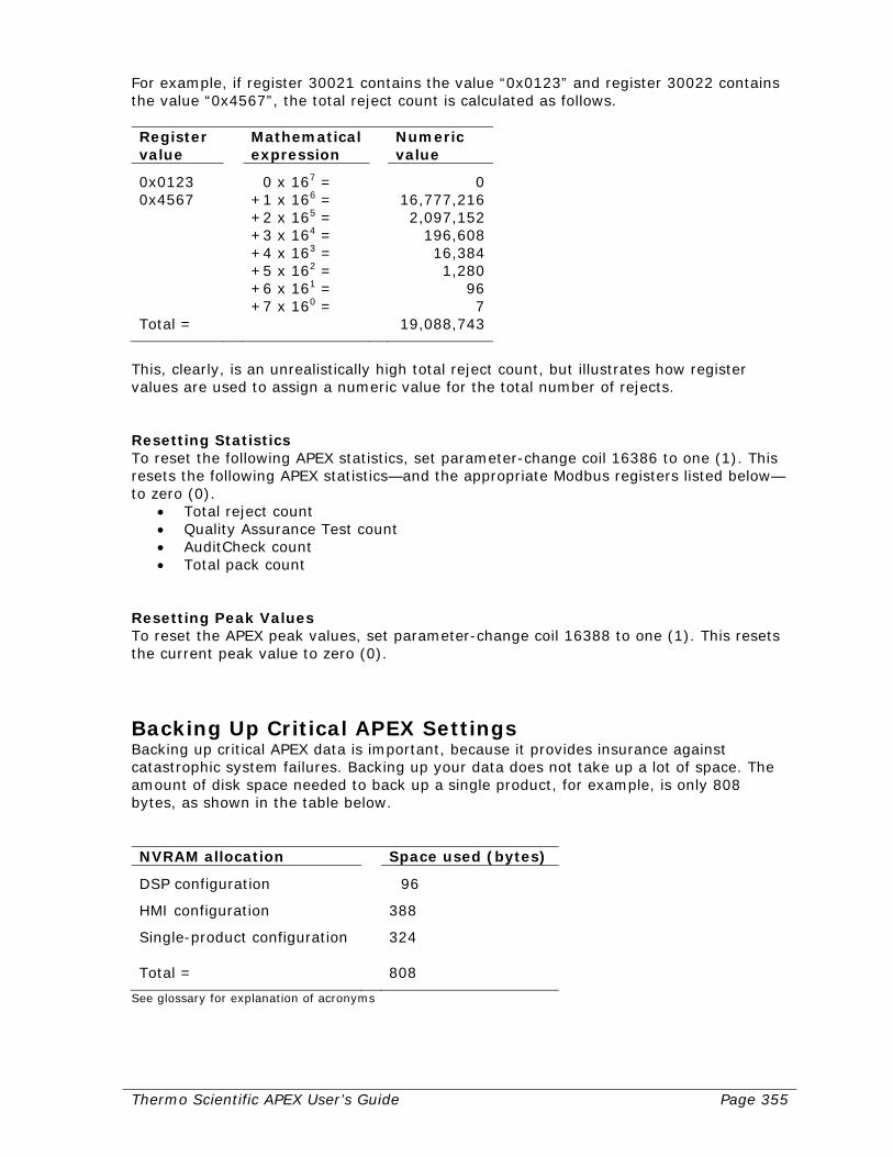
Thermo Scientific APEX User’s Guide Page 355
For example, if register 30021 contains the value “0x0123” and register 30022 contains the value “0x4567”, the total reject count is calculated as follows. Register value
Mathematical expression
Numeric value
0x0123 0 x 167 = 0 0x4567 +1 x 166 = 16,777,216 +2 x 165 = 2,097,152 +3 x 164 = 196,608 +4 x 163 = 16,384 +5 x 162 = 1,280 +6 x 161 = 96 +7 x 160 = 7 Total = 19,088,743
This, clearly, is an unrealistically high total reject count, but illustrates how register values are used to assign a numeric value for the total number of rejects. Resetting Statistics To reset the following APEX statistics, set parameter-change coil 16386 to one (1). This resets the following APEX statistics—and the appropriate Modbus registers listed below—to zero (0).
• Total reject count • Quality Assurance Test count • AuditCheck count • Total pack count
Resetting Peak Values To reset the APEX peak values, set parameter-change coil 16388 to one (1). This resets the current peak value to zero (0).
Backing Up Critical APEX Settings Backing up critical APEX data is important, because it provides insurance against catastrophic system failures. Backing up your data does not take up a lot of space. The amount of disk space needed to back up a single product, for example, is only 808 bytes, as shown in the table below. NVRAM allocation Space used (bytes)
DSP configuration 96
HMI configuration 388
Single-product configuration 324 Total = 808
See glossary for explanation of acronyms
Page 356 Thermo Scientific APEX User’s Guide
In addition, backing up subsequent products (after the first product has been backed up), only uses 324 additional bytes, because all of the detector’s global parameters (such as model type, language setting, preferred units of measure, and so forth) have already been backed up. Overview of Backing Up/Restoring Your APEX Settings The instructions given below are meant solely to provide you with an overview about how to set up an automated process for backing up and restoring your critical APEX settings. As a result, specific data-storage details are not included. In addition, please note that the product parameters are only assessable for the currently selected APEX product. This means that, in order to do a complete product back-up, you must back up the settings for each product separately (using the appropriate product number). Backing Up Your APEX Settings 1) Read all machine settings and store them to a data file. All machine settings are
labeled with an M in the “Data Type” column in the detailed list of Modbus registers (see pages 357–365).
2) Write product number 001 to register 41045, and set parameter-change coil 16385
to one (1). 3) Read all product settings and store to a data file. These product settings—please
note—relate only to product 001. All product settings are labeled with a P in the “Data Type” column in the table of registers.
4) Write product number 002 to register 41045, and set parameter-change coil 16385
to one (1). 5) Read all product settings and store to a data file. These product settings—please
note—relate only to product 002. 6) Continue until all your products are backed up. Restoring Your APEX Settings 1) Write all machine settings from a data file to the corresponding registers. 2) Write product number 001 to register 41045, and set parameter-change coil 16385
to one (1). 3) Write all product settings for product 001 from a data file to the corresponding
registers. 4) Write product number 002 to register 41045, and set parameter-change coil 16385
to one (1). 5) Write all product settings for product 002 from a data file to the corresponding
registers. 6) Continue until all your products are restored.
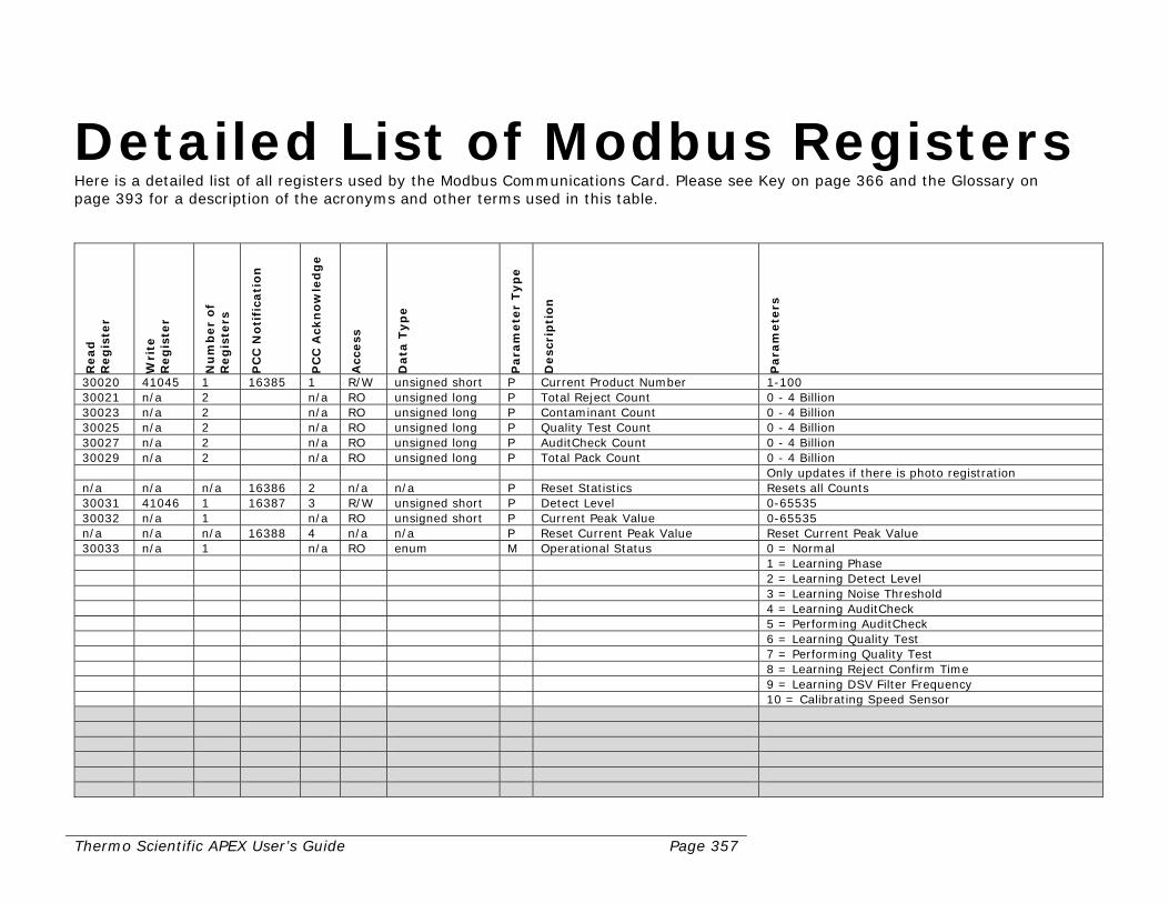
Thermo Scientific APEX User’s Guide Page 357
Detailed List of Modbus Registers Here is a detailed list of all registers used by the Modbus Communications Card. Please see Key on page 366 and the Glossary on page 393 for a description of the acronyms and other terms used in this table.
Read
R
eg
iste
r
Wri
te
Reg
iste
r
Nu
mb
er
of
Reg
iste
rs
PC
C N
oti
fica
tio
n
PC
C A
ckn
ow
led
ge
Acc
ess
Data
Typ
e
Para
mete
r Typ
e
Desc
rip
tio
n
Para
mete
rs
30020 41045 1 16385 1 R/W unsigned short P Current Product Number 1-100 30021 n/a 2 n/a RO unsigned long P Total Reject Count 0 - 4 Billion 30023 n/a 2 n/a RO unsigned long P Contaminant Count 0 - 4 Billion 30025 n/a 2 n/a RO unsigned long P Quality Test Count 0 - 4 Billion 30027 n/a 2 n/a RO unsigned long P AuditCheck Count 0 - 4 Billion 30029 n/a 2 n/a RO unsigned long P Total Pack Count 0 - 4 Billion Only updates if there is photo registration n/a n/a n/a 16386 2 n/a n/a P Reset Statistics Resets all Counts 30031 41046 1 16387 3 R/W unsigned short P Detect Level 0-65535 30032 n/a 1 n/a RO unsigned short P Current Peak Value 0-65535 n/a n/a n/a 16388 4 n/a n/a P Reset Current Peak Value Reset Current Peak Value 30033 n/a 1 n/a RO enum M Operational Status 0 = Normal 1 = Learning Phase 2 = Learning Detect Level 3 = Learning Noise Threshold 4 = Learning AuditCheck 5 = Performing AuditCheck 6 = Learning Quality Test 7 = Performing Quality Test 8 = Learning Reject Confirm Time 9 = Learning DSV Filter Frequency 10 = Calibrating Speed Sensor
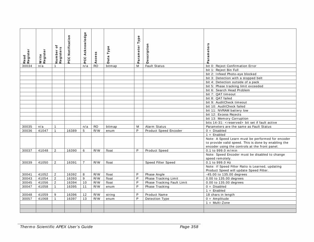
Thermo Scientific APEX User’s Guide Page 358
Read
R
eg
iste
r
Wri
te
Reg
iste
r
Nu
mb
er
of
Reg
iste
rs
PC
C N
oti
fica
tio
n
PC
C A
ckn
ow
led
ge
Acc
ess
Data
Typ
e
Para
mete
r Typ
e
Desc
rip
tio
n
Para
mete
rs
30034 n/a 1 n/a RO bitmap M Fault Status bit 0: Reject Confirmation Error bit 1: Reject Bin Full bit 2: Infeed Photo-eye blocked bit 3: Detection with a stopped belt bit 4: Detection outside of a pack bit 5: Phase tracking limit exceeded bit 6: Search Head Problem bit 7: QAT timeout bit 8: QAT failed bit 9: AuditCheck timeout bit 10: AuditCheck failed bit 11: NVRAM battery low bit 12: Excess Rejects bit 13: Memory Corruption bits 14-31: <reserved> bit set if fault active 30035 n/a 1 n/a RO bitmap M Alarm Status Parameters are the same as Fault Status 30036 41047 1 16389 5 R/W enum P Product Speed Encoder 0 = Disabled 1 = Enabled Note: A Speed Learn must be performed for encoder
to provide valid speed. This is done by enabling the encoder using the controls at the front panel.
30037 41048 2 16390 6 R/W float P Product Speed 0.1 to 999.0 m/min Note: Speed Encoder must be disabled to change
speed remotely. 30039 41050 2 16391 7 R/W float Speed Filter Speed 0.1 to 999.0 Hz Note: If Speed Filter Ratio is Learned, updating
Product Speed will update Speed Filter. 30041 41052 2 16392 8 R/W float P Phase Angle -45.00 to 135.00 degrees 30043 41054 2 16393 9 R/W float P Phase Tracking Limit 0.00 to 135.00 degrees 30045 41056 2 16394 10 R/W float P Phase Tracking Fault Limit 0.00 to 135.00 degrees 30047 41058 1 16395 11 R/W enum P Phase Tracking 0 = Disabled 1 = Enabled 30048 41059 9 16396 12 R/W string P Product Name 18 chars in length 30057 41068 1 16397 13 R/W enum P Detection Type 0 = Amplitude 1 = Multi-Zone

Thermo Scientific APEX User’s Guide Page 359
Read
R
eg
iste
r
Wri
te
Reg
iste
r
Nu
mb
er
of
Reg
iste
rs
PC
C N
oti
fica
tio
n
PC
C A
ckn
ow
led
ge
Acc
ess
Data
Typ
e
Para
mete
r Typ
e
Desc
rip
tio
n
Para
mete
rs
30058 41069 1 16398 14 R/W enum P Detection Inhibited 0 = Disabled 1 = Enabled 30059 41070 1 16399 15 R/W enum P Photo Registration Setting the Photo Registration will also reset the
statistics. 0 = No Photo Eye 1 = Leading Edge 2 = Middle 3 = Length 30060 41071 1 16400 16 R/W unsigned short P Package Length 0 to 5,000 mm 30061 41072 1 16401 17 R/W unsigned short P Package Gap 0 to 100% 30062 41073 1 16402 18 R/W unsigned short P Detection No-pack Distance 0 to 5,000 mm 30063 41074 1 16403 19 R/W bitmap Rejecter Configuration Bit 0: Reject 1 - (0) Normal or (1) Latching Bit 1: Reject 1 - (0) Non-inverted or (1) Inverted Bit 2: Reject 2- Contaminant Reject 30064 41075 1 16404 20 R/W unsigned short P Rejecter 1 Delay 0 to 5,000 mm 30065 41076 1 16405 21 R/W unsigned short P Rejecter 1 Duration Distance 0 to 20,000 mm 30066 41077 1 16406 22 R/W unsigned short P Rejecter 1 Duration Time 0 to 9990 ms 30067 41078 1 16407 23 R/W unsigned short P Reject Confirm 1 Time 0 to 9990 ms 30068 41079 1 16408 24 R/W unsigned short P Reject Confirm 2 Time 0 to 9990 ms 30069 41080 1 16409 25 R/W unsigned short P Rejecter 2 Delay 0 to 5,000 mm 30070 41081 1 16410 26 R/W unsigned short P Rejecter 2 Duration Distance 0 to 20,000 mm 30071 41082 1 16411 27 R/W unsigned short P Rejecter 2 Duration Time 0 to 9990 ms 30072 41083 1 16412 28 R/W unsigned short P Reject Suppression Time 0 to 9990 ms 30073 41084 1 16413 29 R/W unsigned short P Reject Suppression Attenuation 0 to 100% 30074 41085 1 16414 30 R/W bitmap P Reject Suppression Trigger Source Bit 0: External Trigger Bit 1: Reject Output 30075 41086 1 16415 31 R/W enum P PNR Filter 0 = Disabled 1 = Enabled 30076 41087 1 16416 32 R/W enum P QNR Filter 0 = Disabled 1 = Enabled 30077 41088 1 16417 33 R/W enum P CLX Filter 0 = Disabled 256 = CLX Ratio of 1 512 = CLX Ratio of 2 768 = CLX Ratio of 3

Thermo Scientific APEX User’s Guide Page 360
Read
R
eg
iste
r
Wri
te
Reg
iste
r
Nu
mb
er
of
Reg
iste
rs
PC
C N
oti
fica
tio
n
PC
C A
ckn
ow
led
ge
Acc
ess
Data
Typ
e
Para
mete
r Typ
e
Desc
rip
tio
n
Para
mete
rs
30078 41089 1 16418 34 R/W enum P Search Head Frequency 0 = Low Frequency 1 = High Frequency 30079 41090 1 16419 35 R/W enum P Search Head Gain 0 = Low Gain 1 = High Gain 30080 41091 1 16420 36 R/W unsigned short P Resistive (R)Threshold 0 to 65535 30081 41092 1 16421 37 R/W unsigned short P Reactive (X) Threshold 0 to 65535 30082 41093 1 16422 38 R/W bitmap P Auto Learn Behavior Each Bit Locks out a particular stage of the Auto Learn Bit 0: Enable Phase Lock Bit 1: Enable Detect Level Lock Bit 2: Enable AuditCheck Lock 30083 41094 1 16423 39 R/W unsigned short P AuditCheck Time Interval 0 to 999 minutes 30084 41095 1 16424 40 R/W unsigned short P AuditCheck Fault Timeout 0 to 99 minutes 30085 41096 1 16425 41 R/W enum P AuditCheck Reject Device 0 = None 1 - Rejecter 1 2= Rejecter 2 30086 41097 1 16426 42 R/W unsigned short P AuditCheck Peak Warning
Tolerance 0 to 99%
30087 41098 1 16427 43 R/W unsigned short P AuditCheck Peak Alarm Tolerance 0 to 99% 30088 41099 1 16428 44 R/W unsigned short P AuditCheck Peak Fault Tolerance 0 to 99% 30089 41100 1 16429 45 R/W unsigned short P AuditCheck Phase Warning
Tolerance 0 to 99 degrees
30090 41101 1 16430 46 R/W unsigned short P AuditCheck Phase Alarm Tolerance 0 to 99 degrees 30091 41102 1 16431 47 R/W unsigned short P AuditCheck Phase Fault Tolerance 0 to 99 degrees 30092 n/a 1 n/a n/a RO unsigned short P AuditCheck Learned Peak Average 0 to 65535 30093 n/a 1 n/a n/a RO unsigned short P AuditCheck Learned Peak - Test 1 0 to 65535 30094 n/a 1 n/a n/a RO unsigned short P AuditCheck Learned Peak - Test 2 0 to 65535 30095 n/a 1 n/a n/a RO unsigned short P AuditCheck Learned Peak - Test 3 0 to 65535 30096 n/a 2 n/a n/a RO float P AuditCheck Learned Phase
Average -45.00 to 135.00 degrees
30098 n/a 2 n/a n/a RO float P AuditCheck Learned Speed Average
0.1 to 999.0 m/min
30100 n/a 2 n/a n/a RO float P AuditCheck Learned Phase Angle - Test 1
-45.00 to 135.00 degrees
30102 n/a 2 n/a n/a RO float P AuditCheck Learned Speed - Test 1 0.1 to 999.0 m/min 30104 n/a 2 n/a n/a RO float P AuditCheck Learned Phase Angle -
Test 2 -45.00 to 135.00 degrees
30106 n/a 2 n/a n/a RO float P AuditCheck Learned Speed - Test 2 0.1 to 999.0 m/min
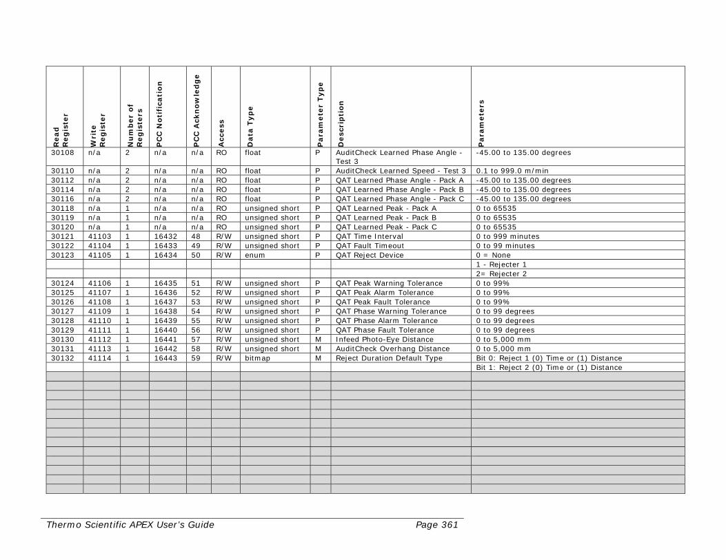
Thermo Scientific APEX User’s Guide Page 361
Read
R
eg
iste
r
Wri
te
Reg
iste
r
Nu
mb
er
of
Reg
iste
rs
PC
C N
oti
fica
tio
n
PC
C A
ckn
ow
led
ge
Acc
ess
Data
Typ
e
Para
mete
r Typ
e
Desc
rip
tio
n
Para
mete
rs
30108 n/a 2 n/a n/a RO float P AuditCheck Learned Phase Angle - Test 3
-45.00 to 135.00 degrees
30110 n/a 2 n/a n/a RO float P AuditCheck Learned Speed - Test 3 0.1 to 999.0 m/min 30112 n/a 2 n/a n/a RO float P QAT Learned Phase Angle - Pack A -45.00 to 135.00 degrees 30114 n/a 2 n/a n/a RO float P QAT Learned Phase Angle - Pack B -45.00 to 135.00 degrees 30116 n/a 2 n/a n/a RO float P QAT Learned Phase Angle - Pack C -45.00 to 135.00 degrees 30118 n/a 1 n/a n/a RO unsigned short P QAT Learned Peak - Pack A 0 to 65535 30119 n/a 1 n/a n/a RO unsigned short P QAT Learned Peak - Pack B 0 to 65535 30120 n/a 1 n/a n/a RO unsigned short P QAT Learned Peak - Pack C 0 to 65535 30121 41103 1 16432 48 R/W unsigned short P QAT Time Interval 0 to 999 minutes 30122 41104 1 16433 49 R/W unsigned short P QAT Fault Timeout 0 to 99 minutes 30123 41105 1 16434 50 R/W enum P QAT Reject Device 0 = None 1 - Rejecter 1 2= Rejecter 2 30124 41106 1 16435 51 R/W unsigned short P QAT Peak Warning Tolerance 0 to 99% 30125 41107 1 16436 52 R/W unsigned short P QAT Peak Alarm Tolerance 0 to 99% 30126 41108 1 16437 53 R/W unsigned short P QAT Peak Fault Tolerance 0 to 99% 30127 41109 1 16438 54 R/W unsigned short P QAT Phase Warning Tolerance 0 to 99 degrees 30128 41110 1 16439 55 R/W unsigned short P QAT Phase Alarm Tolerance 0 to 99 degrees 30129 41111 1 16440 56 R/W unsigned short P QAT Phase Fault Tolerance 0 to 99 degrees 30130 41112 1 16441 57 R/W unsigned short M Infeed Photo-Eye Distance 0 to 5,000 mm 30131 41113 1 16442 58 R/W unsigned short M AuditCheck Overhang Distance 0 to 5,000 mm 30132 41114 1 16443 59 R/W bitmap M Reject Duration Default Type Bit 0: Reject 1 (0) Time or (1) Distance Bit 1: Reject 2 (0) Time or (1) Distance
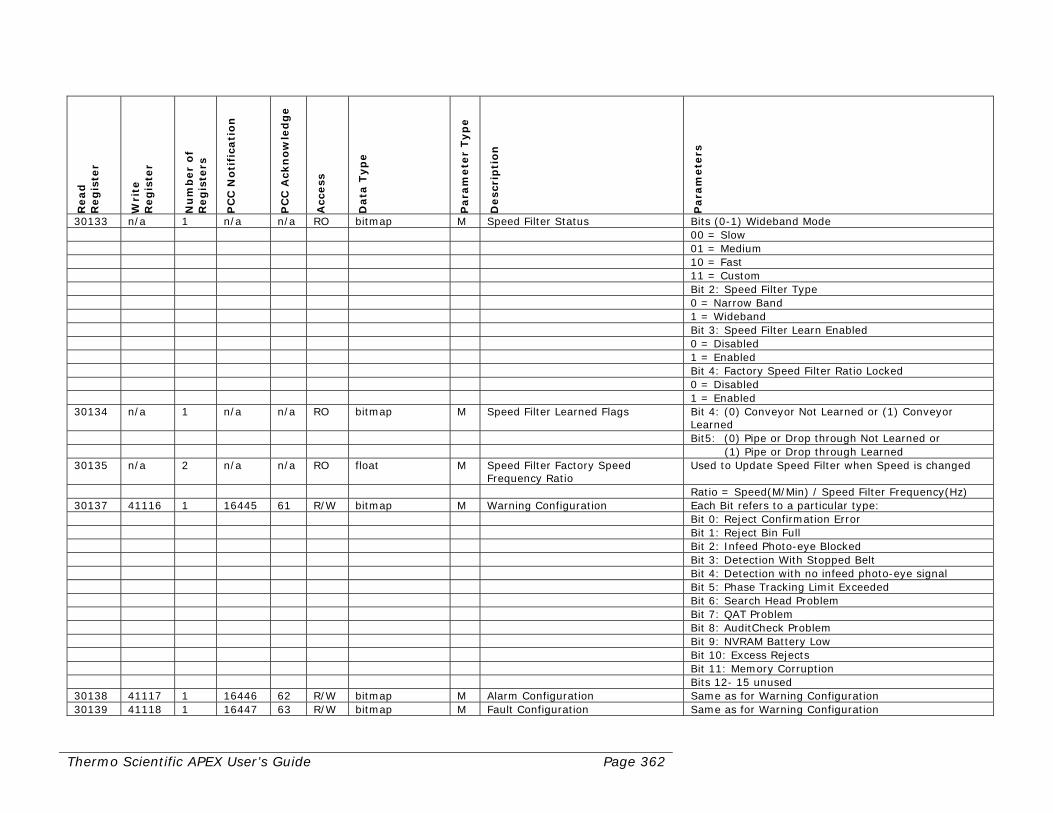
Thermo Scientific APEX User’s Guide Page 362
Read
R
eg
iste
r
Wri
te
Reg
iste
r
Nu
mb
er
of
Reg
iste
rs
PC
C N
oti
fica
tio
n
PC
C A
ckn
ow
led
ge
Acc
ess
Data
Typ
e
Para
mete
r Typ
e
Desc
rip
tio
n
Para
mete
rs
30133 n/a 1 n/a n/a RO bitmap M Speed Filter Status Bits (0-1) Wideband Mode 00 = Slow 01 = Medium 10 = Fast 11 = Custom Bit 2: Speed Filter Type 0 = Narrow Band 1 = Wideband Bit 3: Speed Filter Learn Enabled 0 = Disabled 1 = Enabled Bit 4: Factory Speed Filter Ratio Locked 0 = Disabled 1 = Enabled 30134 n/a 1 n/a n/a RO bitmap M Speed Filter Learned Flags Bit 4: (0) Conveyor Not Learned or (1) Conveyor
Learned Bit5: (0) Pipe or Drop through Not Learned or (1) Pipe or Drop through Learned 30135 n/a 2 n/a n/a RO float M Speed Filter Factory Speed
Frequency Ratio Used to Update Speed Filter when Speed is changed
Ratio = Speed(M/Min) / Speed Filter Frequency(Hz) 30137 41116 1 16445 61 R/W bitmap M Warning Configuration Each Bit refers to a particular type: Bit 0: Reject Confirmation Error Bit 1: Reject Bin Full Bit 2: Infeed Photo-eye Blocked Bit 3: Detection With Stopped Belt Bit 4: Detection with no infeed photo-eye signal Bit 5: Phase Tracking Limit Exceeded Bit 6: Search Head Problem Bit 7: QAT Problem Bit 8: AuditCheck Problem Bit 9: NVRAM Battery Low Bit 10: Excess Rejects Bit 11: Memory Corruption Bits 12- 15 unused 30138 41117 1 16446 62 R/W bitmap M Alarm Configuration Same as for Warning Configuration 30139 41118 1 16447 63 R/W bitmap M Fault Configuration Same as for Warning Configuration

Thermo Scientific APEX User’s Guide Page 363
Read
R
eg
iste
r
Wri
te
Reg
iste
r
Nu
mb
er
of
Reg
iste
rs
PC
C N
oti
fica
tio
n
PC
C A
ckn
ow
led
ge
Acc
ess
Data
Typ
e
Para
mete
r Typ
e
Desc
rip
tio
n
Para
mete
rs
30140 41119 5 16448 64 R/W string M Machine Identifier 9 chars in length 30145 41124 5 16449 65 R/W string M Printer Batch Code 9 chars in length 30150 41129 1 16450 66 R/W bitmap M Printer Setup Bit 0: Enable Printer Bit 1: Enable End of Day Printout Bit 2: Enable Print Rejects Bit 3: Enable Printout on Power On 30151 n/a 1 n/a n/a RO unsigned short M Current Password Level -1 = Passwords Disabled 0 = Not logged in 1 = Operator 2 = Engineer 3 = Supervisor 30152 41130 1 16451 67 R/W signed short M Infeed Photo Eye Sensor Input Values range from -6 to +6 The number (0-6) specifies the output port 0 = disabled the sign (+ or -) indicates the input polarity if negative input port is inverted 30153 41131 1 16452 68 R/W signed short M Reject Confirm 1 Input Same as For Infeed Photo Eye Sensor 30154 41132 1 16453 69 R/W signed short M Reject Confirm 2 Input Same as For Infeed Photo Eye Sensor 30155 41133 1 16454 70 R/W signed short M Bin Full Input Same as For Infeed Photo Eye Sensor 30156 41134 1 16455 71 R/W signed short M Product Select 1 Input Same as For Infeed Photo Eye Sensor 30157 41135 1 16456 72 R/W signed short M Product Select 2 Input Same as For Infeed Photo Eye Sensor 30158 41136 1 16457 73 R/W signed short M Reject Suppression Input Same as For Infeed Photo Eye Sensor 30159 41137 1 16458 74 R/W signed short M Keylock Input Same as For Infeed Photo Eye Sensor 30160 41138 1 16459 75 R/W unsigned short M Excess Reject Count 1-200 Note in order to update Excess Reject Count Excess Span must also be updated 30161 41139 1 16459 75 R/W unsigned short M Excess Reject Span 1-200 Span must be less than Count Note in order to update Excess Reject Span Excess Count must also be updated
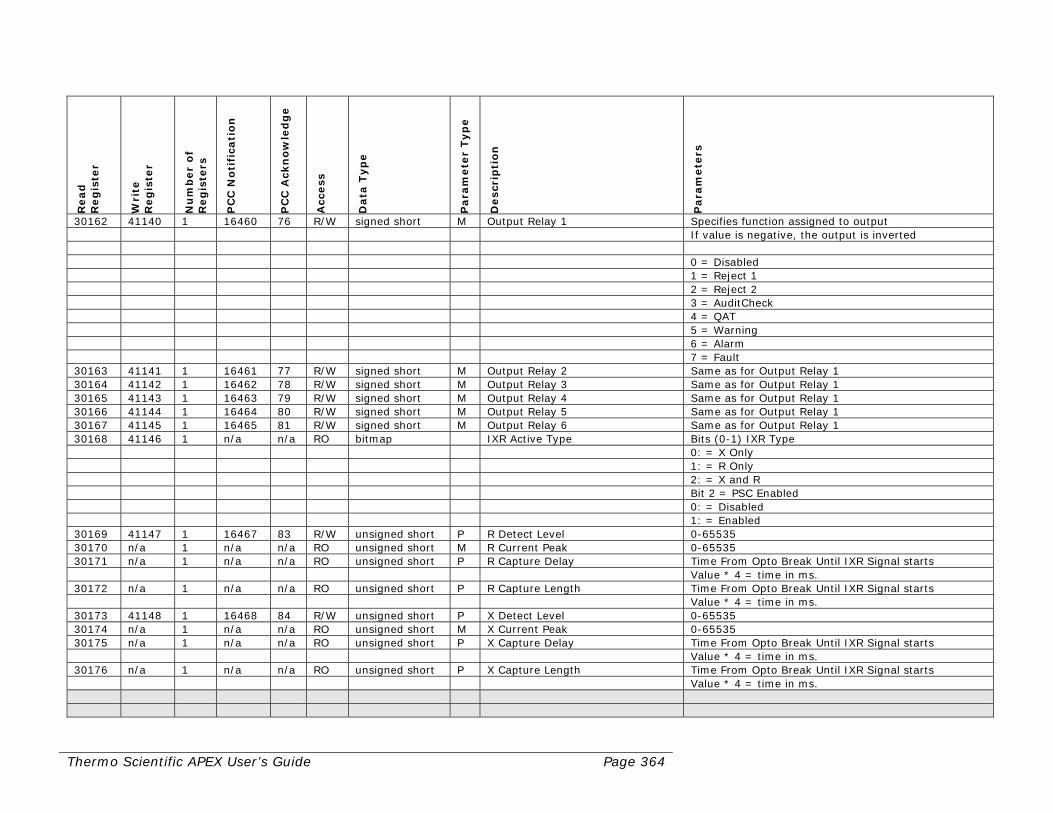
Thermo Scientific APEX User’s Guide Page 364
Read
R
eg
iste
r
Wri
te
Reg
iste
r
Nu
mb
er
of
Reg
iste
rs
PC
C N
oti
fica
tio
n
PC
C A
ckn
ow
led
ge
Acc
ess
Data
Typ
e
Para
mete
r Typ
e
Desc
rip
tio
n
Para
mete
rs
30162 41140 1 16460 76 R/W signed short M Output Relay 1 Specifies function assigned to output If value is negative, the output is inverted 0 = Disabled 1 = Reject 1 2 = Reject 2 3 = AuditCheck 4 = QAT 5 = Warning 6 = Alarm 7 = Fault 30163 41141 1 16461 77 R/W signed short M Output Relay 2 Same as for Output Relay 1 30164 41142 1 16462 78 R/W signed short M Output Relay 3 Same as for Output Relay 1 30165 41143 1 16463 79 R/W signed short M Output Relay 4 Same as for Output Relay 1 30166 41144 1 16464 80 R/W signed short M Output Relay 5 Same as for Output Relay 1 30167 41145 1 16465 81 R/W signed short M Output Relay 6 Same as for Output Relay 1 30168 41146 1 n/a n/a RO bitmap IXR Active Type Bits (0-1) IXR Type 0: = X Only 1: = R Only 2: = X and R Bit 2 = PSC Enabled 0: = Disabled 1: = Enabled 30169 41147 1 16467 83 R/W unsigned short P R Detect Level 0-65535 30170 n/a 1 n/a n/a RO unsigned short M R Current Peak 0-65535 30171 n/a 1 n/a n/a RO unsigned short P R Capture Delay Time From Opto Break Until IXR Signal starts Value * 4 = time in ms. 30172 n/a 1 n/a n/a RO unsigned short P R Capture Length Time From Opto Break Until IXR Signal starts Value * 4 = time in ms. 30173 41148 1 16468 84 R/W unsigned short P X Detect Level 0-65535 30174 n/a 1 n/a n/a RO unsigned short M X Current Peak 0-65535 30175 n/a 1 n/a n/a RO unsigned short P X Capture Delay Time From Opto Break Until IXR Signal starts Value * 4 = time in ms. 30176 n/a 1 n/a n/a RO unsigned short P X Capture Length Time From Opto Break Until IXR Signal starts Value * 4 = time in ms.
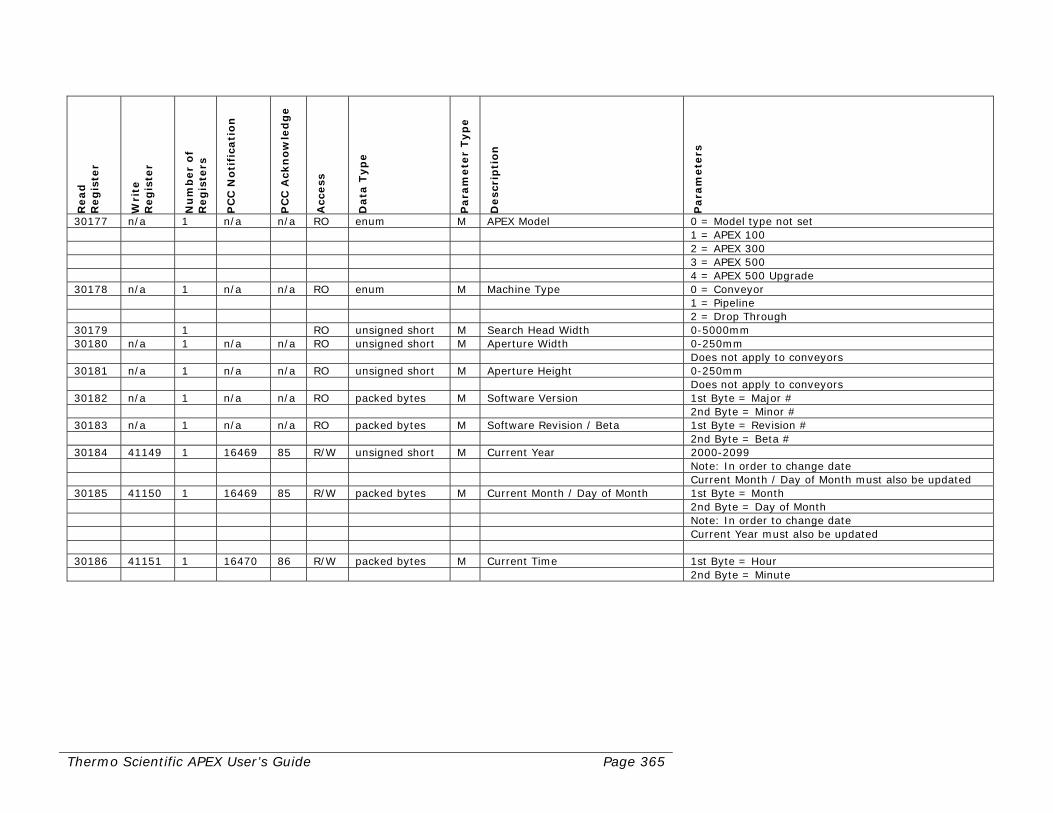
Thermo Scientific APEX User’s Guide Page 365
Read
R
eg
iste
r
Wri
te
Reg
iste
r
Nu
mb
er
of
Reg
iste
rs
PC
C N
oti
fica
tio
n
PC
C A
ckn
ow
led
ge
Acc
ess
Data
Typ
e
Para
mete
r Typ
e
Desc
rip
tio
n
Para
mete
rs
30177 n/a 1 n/a n/a RO enum M APEX Model 0 = Model type not set 1 = APEX 100 2 = APEX 300 3 = APEX 500 4 = APEX 500 Upgrade 30178 n/a 1 n/a n/a RO enum M Machine Type 0 = Conveyor 1 = Pipeline 2 = Drop Through 30179 1 RO unsigned short M Search Head Width 0-5000mm 30180 n/a 1 n/a n/a RO unsigned short M Aperture Width 0-250mm Does not apply to conveyors 30181 n/a 1 n/a n/a RO unsigned short M Aperture Height 0-250mm Does not apply to conveyors 30182 n/a 1 n/a n/a RO packed bytes M Software Version 1st Byte = Major # 2nd Byte = Minor # 30183 n/a 1 n/a n/a RO packed bytes M Software Revision / Beta 1st Byte = Revision # 2nd Byte = Beta # 30184 41149 1 16469 85 R/W unsigned short M Current Year 2000-2099 Note: In order to change date Current Month / Day of Month must also be updated 30185 41150 1 16469 85 R/W packed bytes M Current Month / Day of Month 1st Byte = Month 2nd Byte = Day of Month Note: In order to change date Current Year must also be updated 30186 41151 1 16470 86 R/W packed bytes M Current Time 1st Byte = Hour 2nd Byte = Minute
Thermo Scientific APEX User’s Guide Page 366
Key
M = Machine parameter. A global parameter that defines the underlying
operation of the detector—such as model type (100, 300, 500), application used (conveyor, gravity-feed, pipeline, or Rx), and the preferred units of measure (feet or meters).
P = Product parameter. Any product-related parameter—such as product
name, phase angle, and so on. RO Read-only register R/W Read/write register For other abbreviations and acronyms, see the Glossary at the end of the manual.

Thermo Scientific APEX User’s Guide Page 367
Appendix B—IntelliTrack™ XR

Page 368 Thermo Scientific APEX User’s Guide
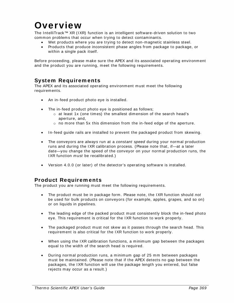
Thermo Scientific APEX User’s Guide Page 369
Overview The IntelliTrack™ XR (IXR) function is an intelligent software-driven solution to two common problems that occur when trying to detect contaminants.
• Wet products where you are trying to detect non-magnetic stainless steel. • Products that produce inconsistent phase angles from package to package, or
within a single pack itself. Before proceeding, please make sure the APEX and its associated operating environment and the product you are running, meet the following requirements.
System Requirements The APEX and its associated operating environment must meet the following requirements.
• An in-feed product photo eye is installed.
• The in-feed product photo eye is positioned as follows;
o at least 1x (one times) the smallest dimension of the search head’s aperture, and,
o no more than 5x this dimension from the in-feed edge of the aperture.
• In-feed guide rails are installed to prevent the packaged product from skewing.
• The conveyors are always run at a constant speed during your normal production runs and during the IXR calibration process. (Please note that, if—at a later date—you change the speed of the conveyor on your normal production runs, the IXR function must be recalibrated.)
• Version 4.0.0 (or later) of the detector’s operating software is installed.
Product Requirements The product you are running must meet the following requirements.
• The product must be in package form. Please note, the IXR function should not
be used for bulk products on conveyors (for example, apples, grapes, and so on) or on liquids in pipelines.
• The leading edge of the packed product must consistently block the in-feed photo eye. This requirement is critical for the IXR function to work properly.
• The packaged product must not skew as it passes through the search head. This requirement is also critical for the IXR function to work properly.
• When using the IXR calibration functions, a minimum gap between the packages equal to the width of the search head is required.
• During normal production runs, a minimum gap of 25 mm between packages must be maintained. (Please note that if the APEX detects no gap between the packages, the IXR function will use the package length you entered, but false rejects may occur as a result.)
Page 370 Thermo Scientific APEX User’s Guide
Discussion of Product Requirements The IXR function may overcome some of the common pitfalls of phasing, but it requires that products are fairly consistent as far as the signal they produce while travelling through the search-head aperture. The products themselves also need to be consistent in content, volume, and presentation (orientation). For example, a product that has varying fat- or salt-contents, may not produce the consistent signal the IXR function requires to detect very small amounts of metallic contamination. The volume of the product is also important, because a larger volume of product will produce a larger signal. As a result, the volume of the product should be consistent to get the best performance from the IXR function. Product presentation is another factor that is crucial to IXR function. Presentation includes the shape and orientation of the product as it passes through the aperture. For example a product that is cube-shaped should have guide rails to insure that it passes through the aperture parallel to belt and through the same part of the aperture each time. Similarly, a rectangular box must pass through the aperture with the same orientation as used when calibrating the product. The IXR function requires a photo eye and a constant speed for each product for the real-time product signal to match the one that is stored in memory during calibration. A variable-speed conveyor can be used, but changing the speed means the IXR function must be recalibrated. Please note, however, that the APEX has an IXR tracking feature that allows small and gradual speed changes over time to be accommodated. In addition, the IXR-tracking feature allows the APEX to accommodate gradual changes in the product signal over time that occur due to slight variations in temperature, belt speed, or other non-contaminant factors. This feature often eliminates false rejects due to this type of variation in the product signal.
The Next Step Before you can start using the IXR function, you must do the following. 1) Set the proper pack length, “detection no-pack” distance, photo-eye distance, and
photo-eye registration. These four parameter must be set for the IXR function to work properly.
2) Enable the IXR function. 3) Calibrate the system. If you encounter problems while setting up the IXR function, please see the “Troubleshooting” section in this appendix, or contact Thermo Fisher Scientific—as described in the “Contacting Thermo Fisher Scientific” section at the end of the manual.

Thermo Scientific APEX User’s Guide Page 371
Setting Up Related Functions For the IXR function to work properly, you must set the following parameters.
• Pack length • “Detection no-pack” distance • In-feed photo-eye distance • Photo-eye registration
The following sections tell you how to set up these four parameters.
Keying In the Pack Length The pack length must be set for the IXR function to work properly. To set the pack length, do the following. 1) Make sure the Main Menu is displayed.
Product Name
2) Press the Go button and page 1 of the product menu appears.
Product Calibrate and Name
3) Press the down-navigation button to highlight page 2 of the product menu.
Product Shape and Flow
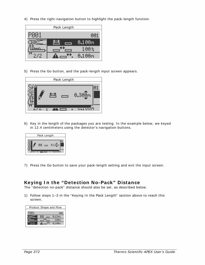
Page 372 Thermo Scientific APEX User’s Guide
4) Press the right-navigation button to highlight the pack-length function.
Pack Length
5) Press the Go button, and the pack-length input screen appears.
Pack Length
6) Key in the length of the packages you are testing. In the example below, we keyed
in 12.4 centimeters using the detector’s navigation buttons.
Pack Length
7) Press the Go button to save your pack-length setting and exit the input screen.
Keying In the “Detection No-Pack” Distance The “detection no-pack” distance should also be set, as described below. 1) Follow steps 1–3 in the “Keying In the Pack Length” section above to reach this
screen.
Product Shape and Flow
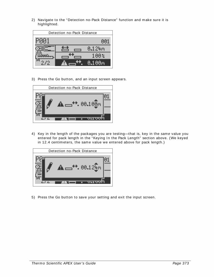
Thermo Scientific APEX User’s Guide Page 373
2) Navigate to the “Detection no-Pack Distance” function and make sure it is highlighted.
Detection no-Pack Distance
3) Press the Go button, and an input screen appears.
Detection no-Pack Distance
4) Key in the length of the packages you are testing—that is, key in the same value you
entered for pack length in the “Keying In the Pack Length” section above. (We keyed in 12.4 centimeters, the same value we entered above for pack length.)
Detection no-Pack Distance
5) Press the Go button to save your setting and exit the input screen.

Page 374 Thermo Scientific APEX User’s Guide
Keying In the In-Feed Photo-Eye Distance The in-feed photo-eye-to-detector distance must be set for the IXR function to work properly. To set the in-feed photo-eye distance, do the following. 1) Take a tape measure and note the distance from the photo-eye (on the upstream or
“in-feed” side of the detector) to the in-feed side of the detector’s search head. 2) Make sure the Main Menu is displayed.
Product Name
3) Navigate to the system and tools menu.
System and Tools
4) Press the Go button and navigate to page 3 of the system and tools menu.
System and Tools Page 3
5) Navigate to the photo-eye set-up menu.
PE Distance and Head Width
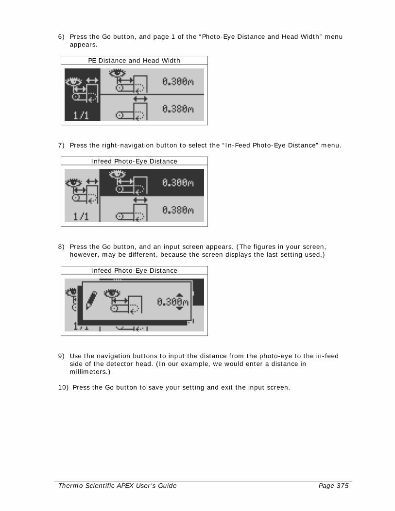
Thermo Scientific APEX User’s Guide Page 375
6) Press the Go button, and page 1 of the “Photo-Eye Distance and Head Width” menu appears.
PE Distance and Head Width
7) Press the right-navigation button to select the “In-Feed Photo-Eye Distance” menu.
Infeed Photo-Eye Distance
8) Press the Go button, and an input screen appears. (The figures in your screen,
however, may be different, because the screen displays the last setting used.)
Infeed Photo-Eye Distance
9) Use the navigation buttons to input the distance from the photo-eye to the in-feed
side of the detector head. (In our example, we would enter a distance in millimeters.)
10) Press the Go button to save your setting and exit the input screen.

Page 376 Thermo Scientific APEX User’s Guide
Enabling Photo-Eye Registration We recommend that you set the photo-eye registration function to detect the middle of your product, but the IXR function will work when the photo-eye registration is set to detect the leading edge or entire length of your product. The key point is, the IXR function will not work if photo-eye registration is set to “Off.” To set photo-eye registration, do the following. 1) Make sure the detector’s Main Menu is displayed.
Product Name
2) Navigate to the reject-totals menu.
Reject Totals
3) Press the Go button and navigate to page 2 of the rejects-totals menu.
Reject Registration and Type
(continued…)

Thermo Scientific APEX User’s Guide Page 377
4) Press the right-navigation button to select the photo-eye registration menu. (The screen below shows that currently the photo-eye registration is set to detect the leading edge of the product.)
Leading Photo Registration
5) Press the Go button repeatedly until the check mark is displayed next to the “detect
the middle of the package” icon, as shown below.
Middle Photo Registration
6) Press the Back button to save your setting and exit the menu.
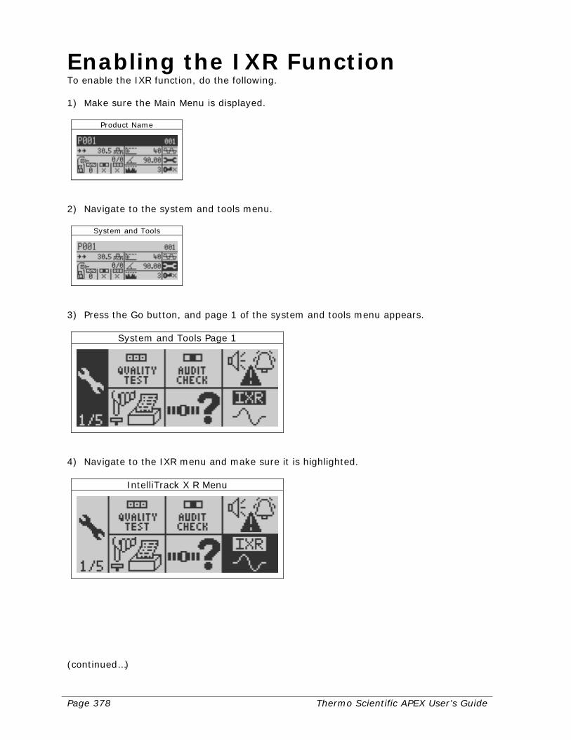
Page 378 Thermo Scientific APEX User’s Guide
Enabling the IXR Function To enable the IXR function, do the following. 1) Make sure the Main Menu is displayed.
Product Name
2) Navigate to the system and tools menu.
System and Tools
3) Press the Go button, and page 1 of the system and tools menu appears.
System and Tools Page 1
4) Navigate to the IXR menu and make sure it is highlighted.
IntelliTrack X R Menu
(continued…)
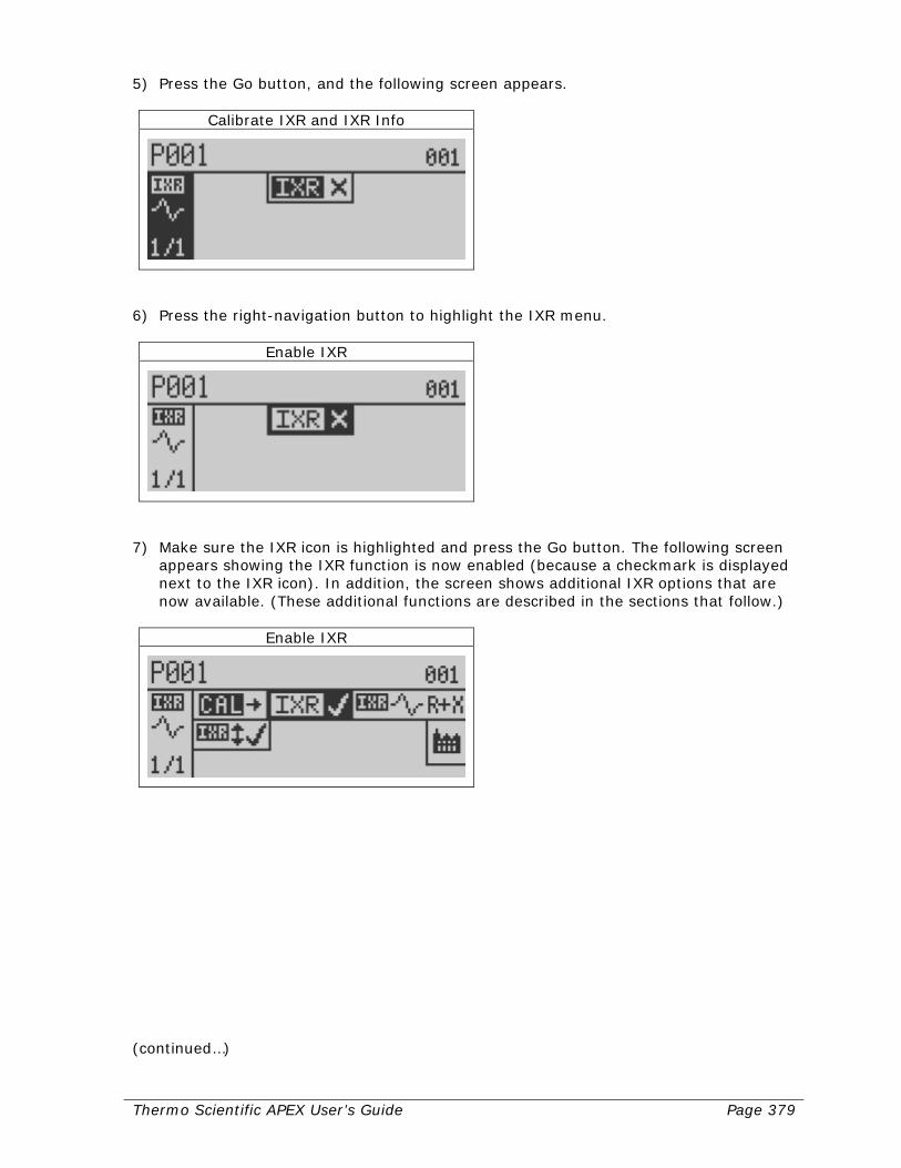
Thermo Scientific APEX User’s Guide Page 379
5) Press the Go button, and the following screen appears.
Calibrate IXR and IXR Info
6) Press the right-navigation button to highlight the IXR menu.
Enable IXR
7) Make sure the IXR icon is highlighted and press the Go button. The following screen
appears showing the IXR function is now enabled (because a checkmark is displayed next to the IXR icon). In addition, the screen shows additional IXR options that are now available. (These additional functions are described in the sections that follow.)
Enable IXR
(continued…)

Page 380 Thermo Scientific APEX User’s Guide
8) Press the Back button repeatedly to return to the Main Menu. Please note that, now the IXR function is active, additional displays have been added to the Main Menu, as shown below. (Please see the “Understanding the IXR Display” section on page 388 for more information about these additional displays.)
Main Menu
Calibrating the IXR Function There are two basic steps to calibrating the IXR function, as follows.
• Learn the X and R noise thresholds.
• Learn the detect levels (for both the X and R signals). In addition, if you are going to use the IXR function for long production runs lasting several hours or days, you should make sure the IXR tracking function is set to “On” (the default value).
Learn the X and R Noise Thresholds Please note it is very important that, while calibrating the X and R noise thresholds, you run the conveyor at exactly the same speed you will use during your normal production runs. Thus, if you decide at a later date, to change the speed of the conveyor during your normal production runs, you must recalibrate the X and R noise thresholds. To calibrate the X and R noise thresholds, do the following. 1) Make sure the Main Menu is displayed.
Product Name
(continued…)
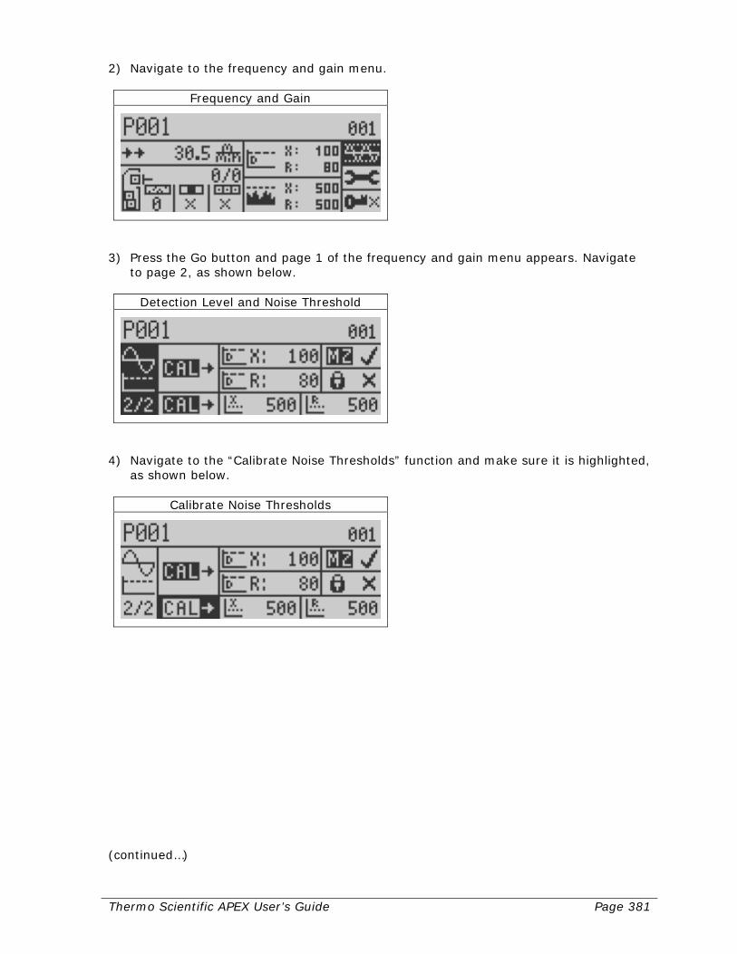
Thermo Scientific APEX User’s Guide Page 381
2) Navigate to the frequency and gain menu.
Frequency and Gain
3) Press the Go button and page 1 of the frequency and gain menu appears. Navigate
to page 2, as shown below.
Detection Level and Noise Threshold
4) Navigate to the “Calibrate Noise Thresholds” function and make sure it is highlighted,
as shown below.
Calibrate Noise Thresholds
(continued…)
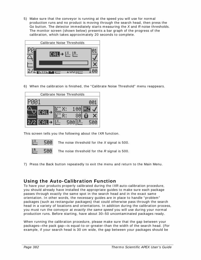
Page 382 Thermo Scientific APEX User’s Guide
5) Make sure that the conveyor is running at the speed you will use for normal production runs and no product is moving through the search head, then press the Go button. The detector immediately starts measuring the X and R noise thresholds. The monitor screen (shown below) presents a bar graph of the progress of the calibration, which takes approximately 20 seconds to complete.
Calibrate Noise Thresholds
6) When the calibration is finished, the “Calibrate Noise Threshold” menu reappears.
Calibrate Noise Thresholds
This screen tells you the following about the IXR function.
The noise threshold for the X signal is 500.
The noise threshold for the R signal is 500.
7) Press the Back button repeatedly to exit the menu and return to the Main Menu.
Using the Auto-Calibration Function To have your products properly calibrated during the IXR auto-calibration procedure, you should already have installed the appropriate guides to make sure each package passes through exactly the same spot in the search head and in the exact same orientation. In other words, the necessary guides are in place to handle “problem” packages (such as rectangular packages) that could otherwise pass through the search head in a variety of locations and orientations. In addition during the calibration process, you must run the conveyor at exactly the same speed you will use during your normal production runs. Before starting, have about 30–50 uncontaminated packages ready. When running the calibration procedure, please make sure that the gap between your packages—the pack gap—is equal-to-or-greater-than the width of the search head. (For example, if your search head is 30 cm wide, the gap between your packages should be
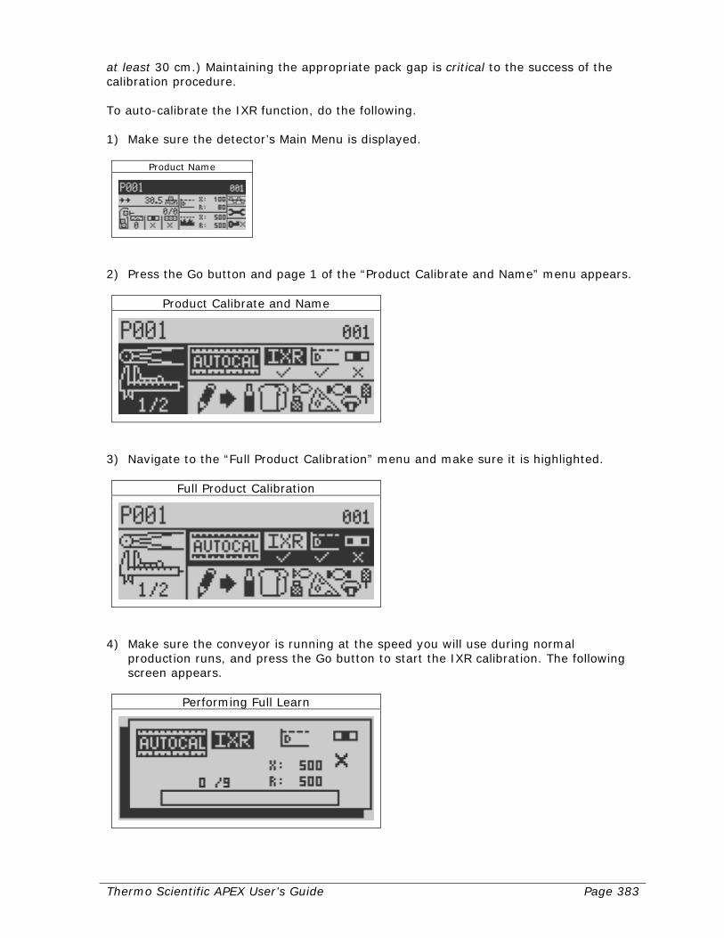
Thermo Scientific APEX User’s Guide Page 383
at least 30 cm.) Maintaining the appropriate pack gap is critical to the success of the calibration procedure. To auto-calibrate the IXR function, do the following. 1) Make sure the detector’s Main Menu is displayed.
Product Name
2) Press the Go button and page 1 of the “Product Calibrate and Name” menu appears.
Product Calibrate and Name
3) Navigate to the “Full Product Calibration” menu and make sure it is highlighted.
Full Product Calibration
4) Make sure the conveyor is running at the speed you will use during normal
production runs, and press the Go button to start the IXR calibration. The following screen appears.
Performing Full Learn
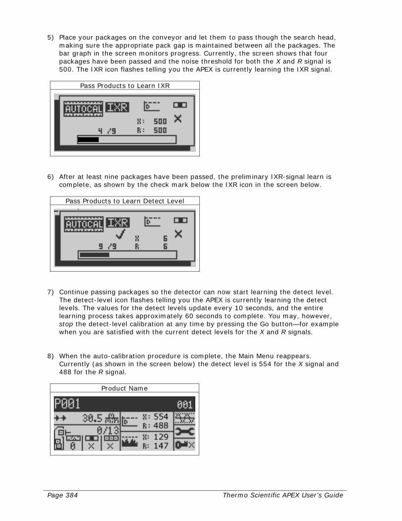
Page 384 Thermo Scientific APEX User’s Guide
5) Place your packages on the conveyor and let them to pass though the search head, making sure the appropriate pack gap is maintained between all the packages. The bar graph in the screen monitors progress. Currently, the screen shows that four packages have been passed and the noise threshold for both the X and R signal is 500. The IXR icon flashes telling you the APEX is currently learning the IXR signal.
Pass Products to Learn IXR
6) After at least nine packages have been passed, the preliminary IXR-signal learn is
complete, as shown by the check mark below the IXR icon in the screen below.
Pass Products to Learn Detect Level
7) Continue passing packages so the detector can now start learning the detect level.
The detect-level icon flashes telling you the APEX is currently learning the detect levels. The values for the detect levels update every 10 seconds, and the entire learning process takes approximately 60 seconds to complete. You may, however, stop the detect-level calibration at any time by pressing the Go button—for example when you are satisfied with the current detect levels for the X and R signals.
8) When the auto-calibration procedure is complete, the Main Menu reappears.
Currently (as shown in the screen below) the detect level is 554 for the X signal and 488 for the R signal.
Product Name
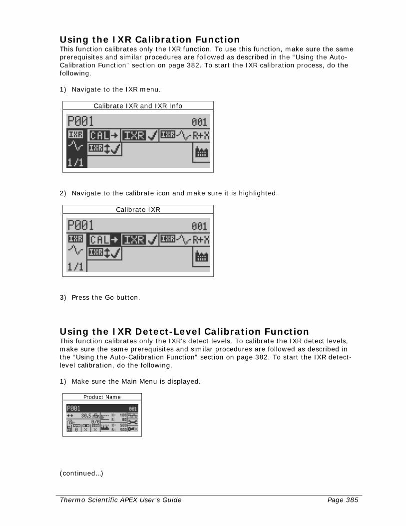
Thermo Scientific APEX User’s Guide Page 385
Using the IXR Calibration Function This function calibrates only the IXR function. To use this function, make sure the same prerequisites and similar procedures are followed as described in the “Using the Auto-Calibration Function” section on page 382. To start the IXR calibration process, do the following. 1) Navigate to the IXR menu.
Calibrate IXR and IXR Info
2) Navigate to the calibrate icon and make sure it is highlighted.
Calibrate IXR
3) Press the Go button.
Using the IXR Detect-Level Calibration Function This function calibrates only the IXR’s detect levels. To calibrate the IXR detect levels, make sure the same prerequisites and similar procedures are followed as described in the “Using the Auto-Calibration Function” section on page 382. To start the IXR detect-level calibration, do the following. 1) Make sure the Main Menu is displayed.
Product Name
(continued…)

Page 386 Thermo Scientific APEX User’s Guide
2) Navigate to the detect-level menu.
Detect Level
3) Press the Go button and page 2 of the “Detection Level and Noise Threshold” menu
appears.
Detection level and Noise Threshold
4) Navigate to the calibrate-detect-level icon and make sure it is highlighted.
Calibrate Detect Level
5) Press the Go button.
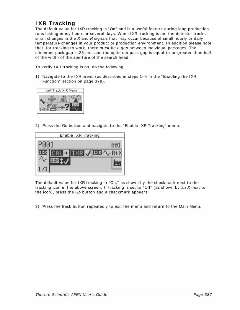
Thermo Scientific APEX User’s Guide Page 387
IXR Tracking The default value for IXR tracking is “On” and is a useful feature during long production runs lasting many hours or several days. When IXR tracking is on, the detector tracks small changes in the X and R signals that may occur because of small hourly or daily temperature changes in your product or production environment. In addition please note that, for tracking to work, there must be a gap between individual packages. The minimum pack gap is 25 mm and the optimum pack gap is equal-to-or-greater-than half of the width of the aperture of the search head. To verify IXR tracking is on, do the following. 1) Navigate to the IXR menu (as described in steps 1–4 in the “Enabling the IXR
Function” section on page 378).
IntelliTrack X R Menu
2) Press the Go button and navigate to the “Enable IXR Tracking” menu.
Enable IXR Tracking
The default value for IXR tracking in “On,” as shown by the checkmark next to the tracking icon in the above screen. If tracking is set to “Off” (as shown by an X next to the icon), press the Go button and a checkmark appears. 3) Press the Back button repeatedly to exit the menu and return to the Main Menu.
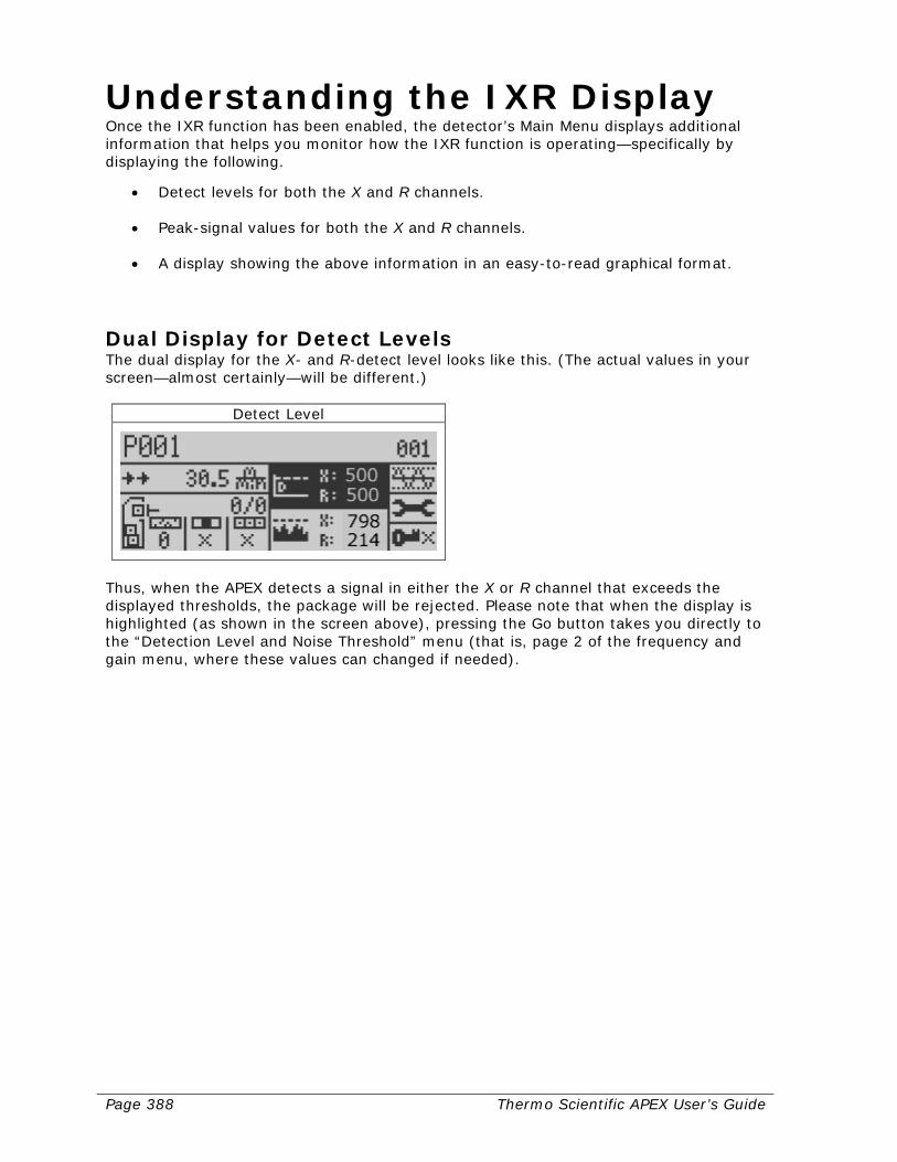
Page 388 Thermo Scientific APEX User’s Guide
Understanding the IXR Display Once the IXR function has been enabled, the detector’s Main Menu displays additional information that helps you monitor how the IXR function is operating—specifically by displaying the following.
• Detect levels for both the X and R channels. • Peak-signal values for both the X and R channels. • A display showing the above information in an easy-to-read graphical format.
Dual Display for Detect Levels The dual display for the X- and R-detect level looks like this. (The actual values in your screen—almost certainly—will be different.)
Detect Level
Thus, when the APEX detects a signal in either the X or R channel that exceeds the displayed thresholds, the package will be rejected. Please note that when the display is highlighted (as shown in the screen above), pressing the Go button takes you directly to the “Detection Level and Noise Threshold” menu (that is, page 2 of the frequency and gain menu, where these values can changed if needed).
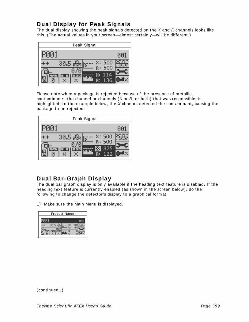
Thermo Scientific APEX User’s Guide Page 389
Dual Display for Peak Signals The dual display showing the peak signals detected on the X and R channels looks like this. (The actual values in your screen—almost certainly—will be different.)
Peak Signal
Please note when a package is rejected because of the presence of metallic contaminants, the channel or channels (X or R, or both) that was responsible, is highlighted. In the example below, the X channel detected the contaminant, causing the package to be rejected.
Peak Signal
Dual Bar-Graph Display The dual bar graph display is only available if the heading text feature is disabled. If the heading text feature is currently enabled (as shown in the screen below), do the following to change the detector’s display to a graphical format. 1) Make sure the Main Menu is displayed.
Product Name
(continued…)
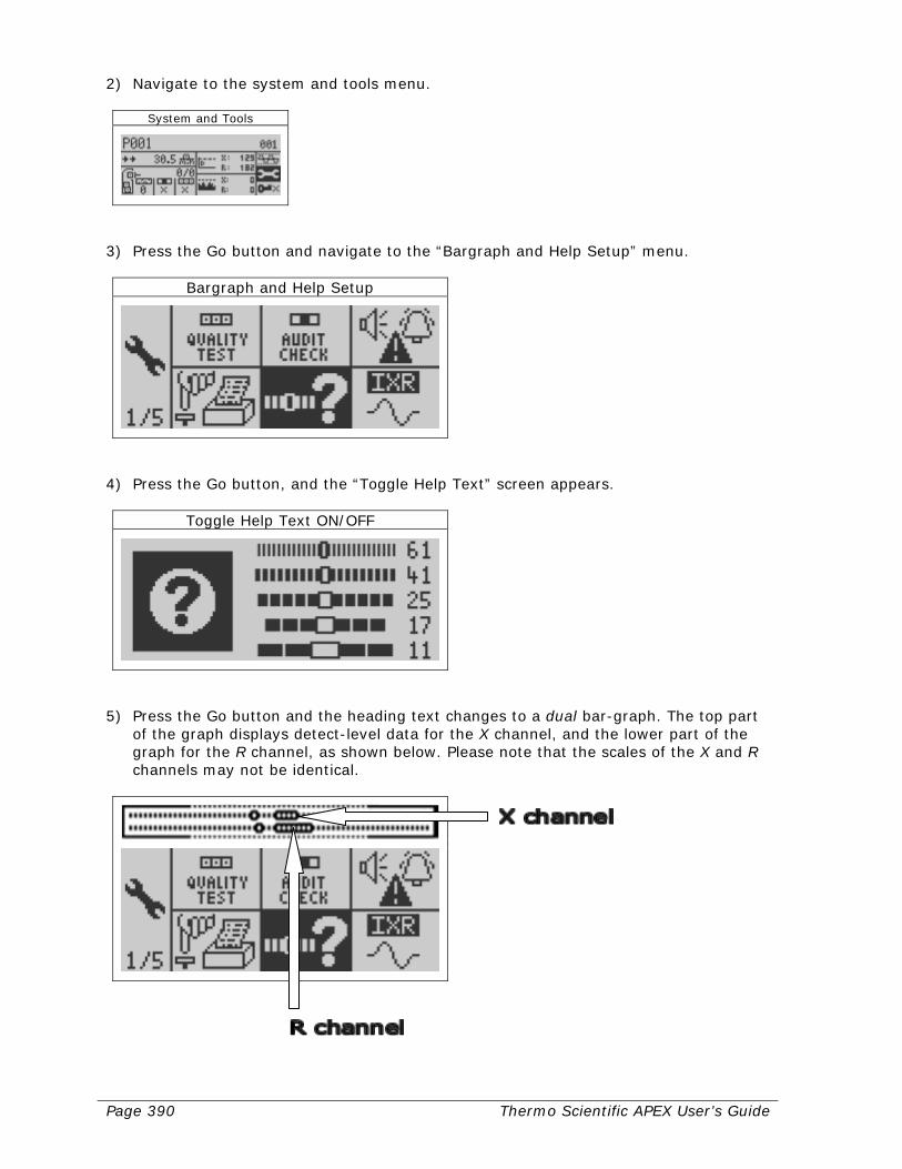
Page 390 Thermo Scientific APEX User’s Guide
2) Navigate to the system and tools menu.
System and Tools
3) Press the Go button and navigate to the “Bargraph and Help Setup” menu.
Bargraph and Help Setup
4) Press the Go button, and the “Toggle Help Text” screen appears.
Toggle Help Text ON/OFF
5) Press the Go button and the heading text changes to a dual bar-graph. The top part
of the graph displays detect-level data for the X channel, and the lower part of the graph for the R channel, as shown below. Please note that the scales of the X and R channels may not be identical.
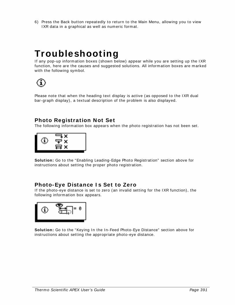
Thermo Scientific APEX User’s Guide Page 391
6) Press the Back button repeatedly to return to the Main Menu, allowing you to view IXR data in a graphical as well as numeric format.
Troubleshooting If any pop-up information boxes (shown below) appear while you are setting up the IXR function, here are the causes and suggested solutions. All information boxes are marked with the following symbol.
Please note that when the heading text display is active (as opposed to the IXR dual bar-graph display), a textual description of the problem is also displayed.
Photo Registration Not Set The following information box appears when the photo registration has not been set.
Solution: Go to the “Enabling Leading-Edge Photo Registration” section above for instructions about setting the proper photo registration.
Photo-Eye Distance Is Set to Zero If the photo-eye distance is set to zero (an invalid setting for the IXR function), the following information box appears.
Solution: Go to the “Keying In the In-Feed Photo-Eye Distance” section above for instructions about setting the appropriate photo-eye distance.
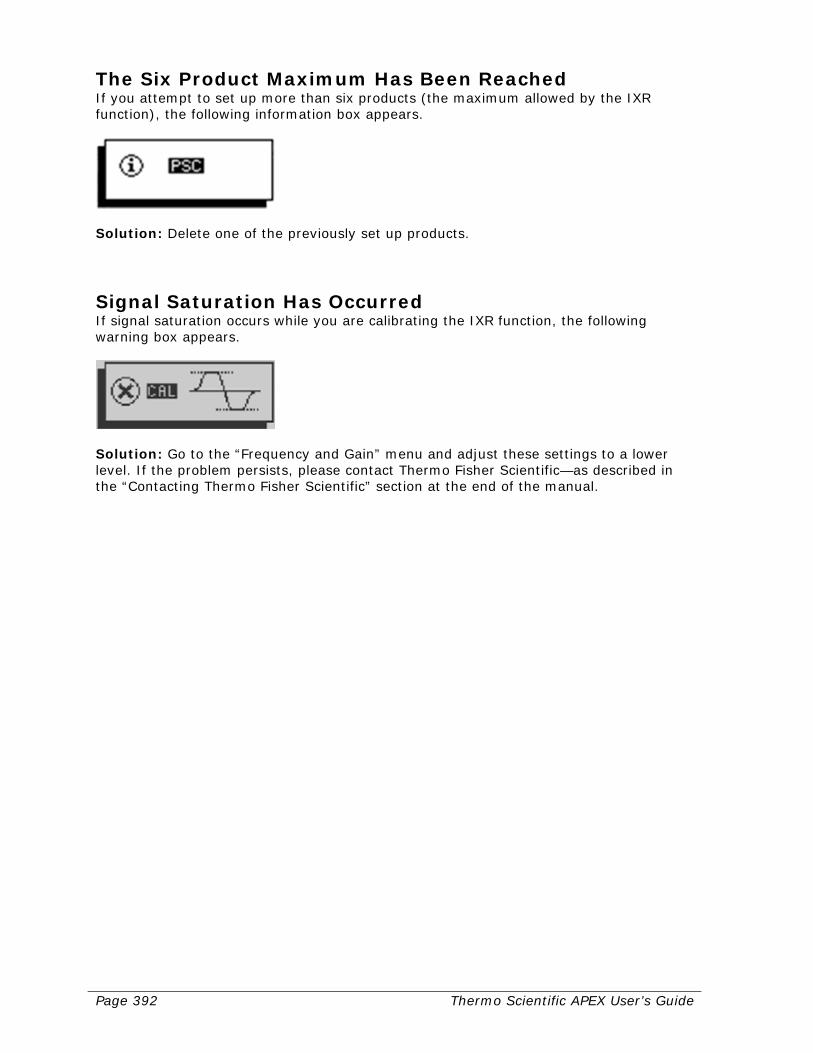
Page 392 Thermo Scientific APEX User’s Guide
The Six Product Maximum Has Been Reached If you attempt to set up more than six products (the maximum allowed by the IXR function), the following information box appears.
Solution: Delete one of the previously set up products.
Signal Saturation Has Occurred If signal saturation occurs while you are calibrating the IXR function, the following warning box appears.
Solution: Go to the “Frequency and Gain” menu and adjust these settings to a lower level. If the problem persists, please contact Thermo Fisher Scientific—as described in the “Contacting Thermo Fisher Scientific” section at the end of the manual.
Thermo Scientific APEX User’s Guide Page 393
Glossary In this glossary, any term in italics, refers to a technical term that is defined elsewhere in the glossary.
Glossary Term Definition
Alarm See WAF Application There are four types of applications: conveyor,
gravity-feed, pipeline, and pharmaceutical. The term describes how product is passed through the detector’s search head.
Application-specific parameter
Parameters that must be set, when using a particular application.
Auto-calibration A function that allows the detector to set the phase
angle, detect level, and AuditCheck settings using test contaminants.
Back button The red button on the detector’s control panel. CAL Calibrate. An abbreviation used in the detector’s
function menus. CLX The clip-X filter, which reduces noise when wet-
products are being tested. Control keys The four icons in the (software-driven) keyboard
screen that allow you to move the cursor left and right, delete a character, and exit from the keyboard screen.
Control Panel This comprises the navigation, Go, and Back buttons;
the indicator lights; and the display panel. CPU Central processing unit Detect level During the auto-calibration procedure, the detector
measures the level of background noise (the amount of background signal in the search head) and multiplies this by a factor of 2–3 to set the detect level. Any signal (excessive noise/contamination) that exceeds the detect level is tagged as contamination. However, when the detect level is properly set, metals—and only metals—will be tagged as contamination.
DHCP Dynamic host-control protocol
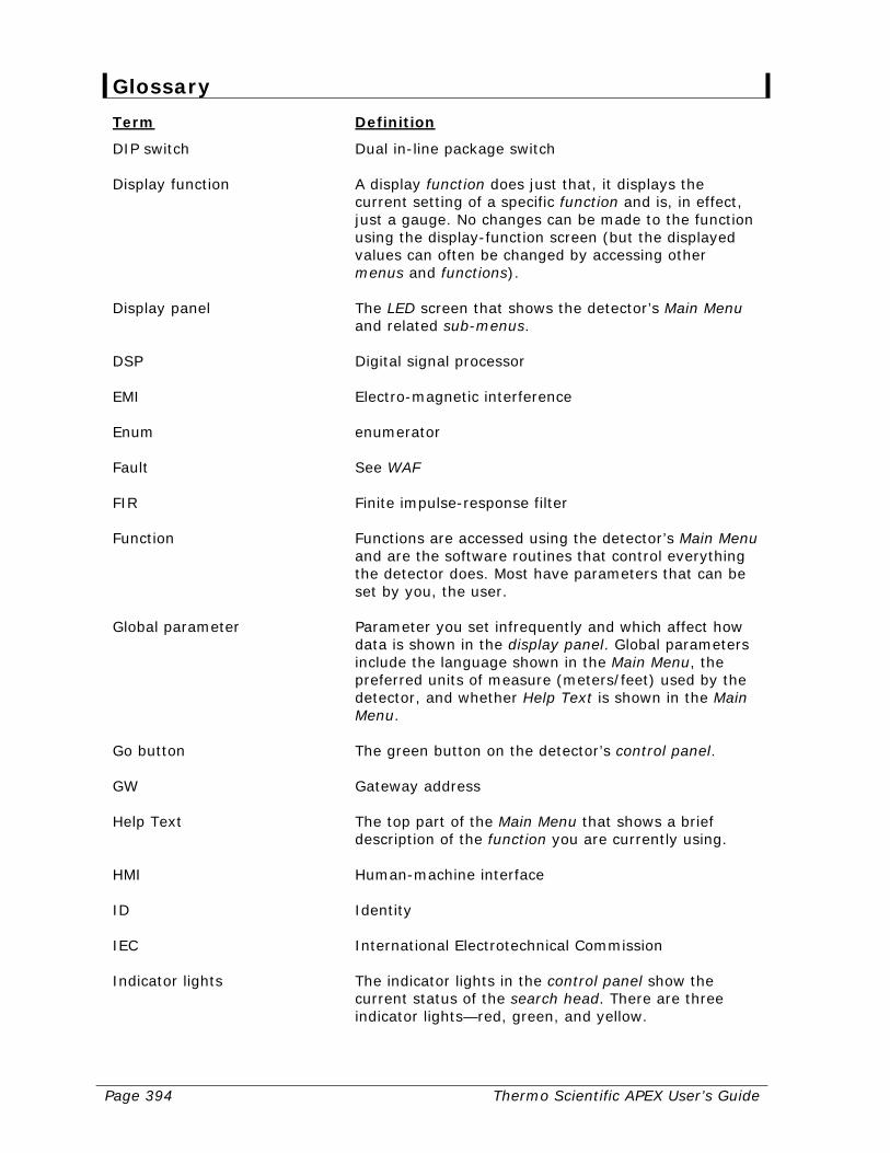
Page 394 Thermo Scientific APEX User’s Guide
Glossary Term Definition
DIP switch Dual in-line package switch Display function A display function does just that, it displays the
current setting of a specific function and is, in effect, just a gauge. No changes can be made to the function using the display-function screen (but the displayed values can often be changed by accessing other menus and functions).
Display panel The LED screen that shows the detector’s Main Menu
and related sub-menus. DSP Digital signal processor EMI Electro-magnetic interference Enum enumerator Fault See WAF FIR Finite impulse-response filter Function Functions are accessed using the detector’s Main Menu
and are the software routines that control everything the detector does. Most have parameters that can be set by you, the user.
Global parameter Parameter you set infrequently and which affect how
data is shown in the display panel. Global parameters include the language shown in the Main Menu, the preferred units of measure (meters/feet) used by the detector, and whether Help Text is shown in the Main Menu.
Go button The green button on the detector’s control panel. GW Gateway address Help Text The top part of the Main Menu that shows a brief
description of the function you are currently using. HMI Human-machine interface ID Identity IEC International Electrotechnical Commission Indicator lights The indicator lights in the control panel show the
current status of the search head. There are three indicator lights—red, green, and yellow.
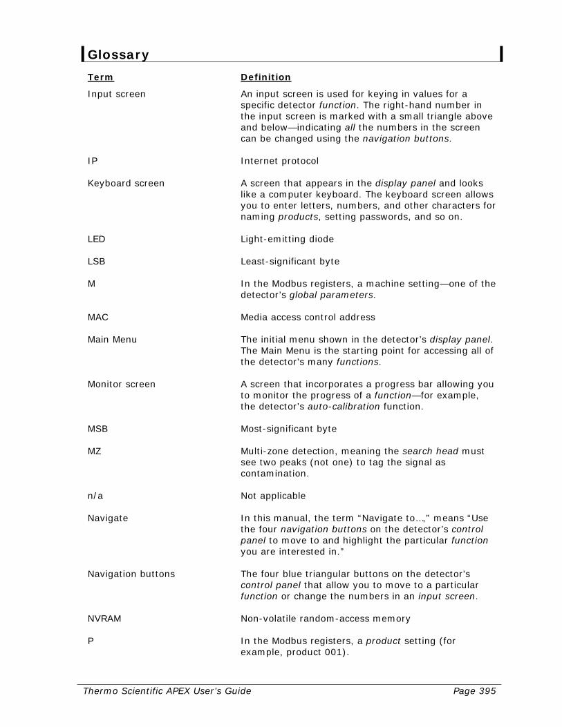
Thermo Scientific APEX User’s Guide Page 395
Glossary Term Definition
Input screen An input screen is used for keying in values for a specific detector function. The right-hand number in the input screen is marked with a small triangle above and below—indicating all the numbers in the screen can be changed using the navigation buttons.
IP Internet protocol Keyboard screen A screen that appears in the display panel and looks
like a computer keyboard. The keyboard screen allows you to enter letters, numbers, and other characters for naming products, setting passwords, and so on.
LED Light-emitting diode LSB Least-significant byte M In the Modbus registers, a machine setting—one of the
detector’s global parameters. MAC Media access control address Main Menu The initial menu shown in the detector’s display panel.
The Main Menu is the starting point for accessing all of the detector’s many functions.
Monitor screen A screen that incorporates a progress bar allowing you
to monitor the progress of a function—for example, the detector’s auto-calibration function.
MSB Most-significant byte MZ Multi-zone detection, meaning the search head must
see two peaks (not one) to tag the signal as contamination.
n/a Not applicable Navigate In this manual, the term “Navigate to…,” means “Use
the four navigation buttons on the detector’s control panel to move to and highlight the particular function you are interested in.”
Navigation buttons The four blue triangular buttons on the detector’s
control panel that allow you to move to a particular function or change the numbers in an input screen.
NVRAM Non-volatile random-access memory P In the Modbus registers, a product setting (for
example, product 001).
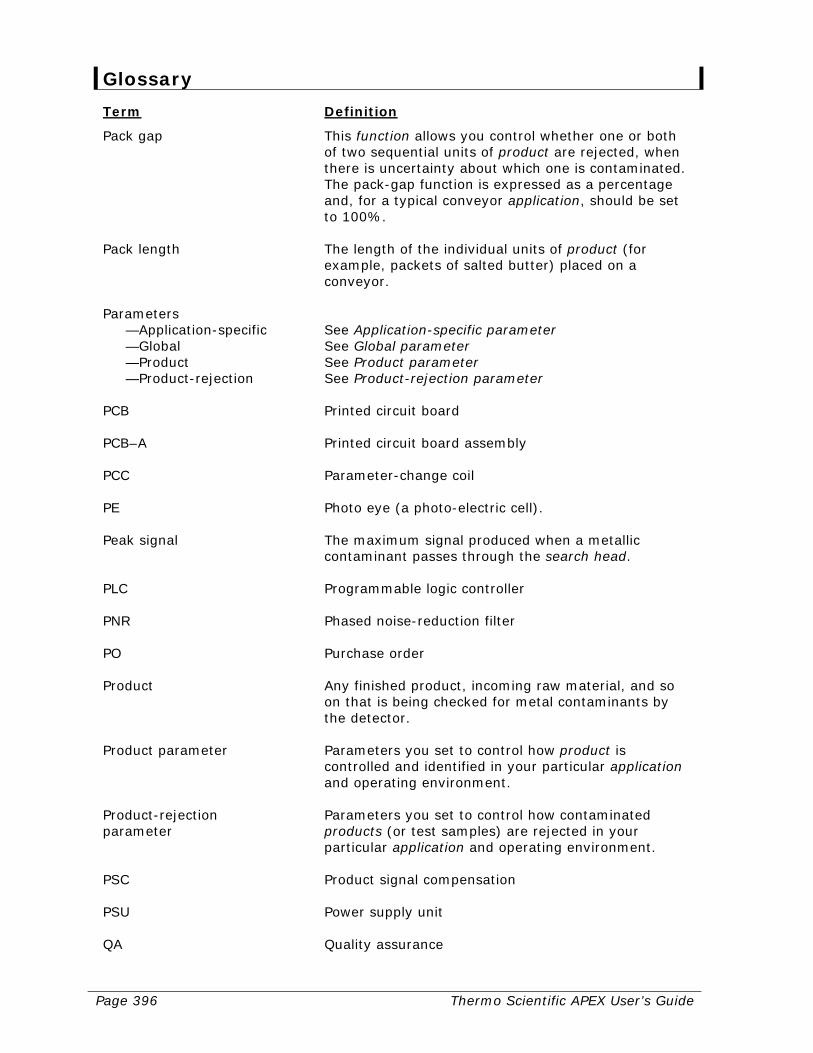
Page 396 Thermo Scientific APEX User’s Guide
Glossary Term Definition
Pack gap This function allows you control whether one or both of two sequential units of product are rejected, when there is uncertainty about which one is contaminated. The pack-gap function is expressed as a percentage and, for a typical conveyor application, should be set to 100%.
Pack length The length of the individual units of product (for
example, packets of salted butter) placed on a conveyor.
Parameters
—Application-specific See Application-specific parameter —Global See Global parameter —Product See Product parameter —Product-rejection See Product-rejection parameter
PCB Printed circuit board PCB–A Printed circuit board assembly PCC Parameter-change coil PE Photo eye (a photo-electric cell). Peak signal The maximum signal produced when a metallic
contaminant passes through the search head. PLC Programmable logic controller PNR Phased noise-reduction filter PO Purchase order Product Any finished product, incoming raw material, and so
on that is being checked for metal contaminants by the detector.
Product parameter Parameters you set to control how product is
controlled and identified in your particular application and operating environment.
Product-rejection parameter
Parameters you set to control how contaminated products (or test samples) are rejected in your particular application and operating environment.
PSC Product signal compensation PSU Power supply unit QA Quality assurance
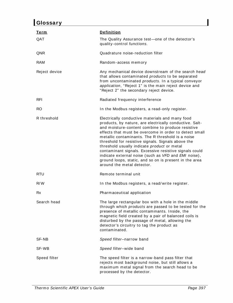
Thermo Scientific APEX User’s Guide Page 397
Glossary Term Definition
QAT The Quality Assurance test—one of the detector’s quality-control functions.
QNR Quadrature noise-reduction filter RAM Random-access memory Reject device Any mechanical device downstream of the search head
that allows contaminated products to be separated from uncontaminated products. In a typical conveyor application, “Reject 1” is the main reject device and “Reject 2” the secondary reject device.
RFI Radiated frequency interference RO In the Modbus registers, a read-only register. R threshold Electrically conductive materials and many food
products, by nature, are electrically conductive. Salt- and moisture-content combine to produce resistive effects that must be overcome in order to detect small metallic contaminants. The R threshold is a noise threshold for resistive signals. Signals above the threshold usually indicate product or metal contaminant signals. Excessive resistive signals could indicate external noise (such as VFD and EMI noise), ground loops, static, and so on is present in the area around the metal detector.
RTU Remote terminal unit R/W In the Modbus registers, a read/write register. Rx Pharmaceutical application Search head The large rectangular box with a hole in the middle
through which products are passed to be tested for the presence of metallic contaminants. Inside, the magnetic field created by a pair of balanced coils is disturbed by the passage of metal, allowing the detector’s circuitry to tag the product as contaminated.
SF-NB Speed filter–narrow band SF-WB Speed filter–wide band Speed filter The speed filter is a narrow-band pass filter that
rejects most background noise, but still allows a maximum metal signal from the search head to be processed by the detector.
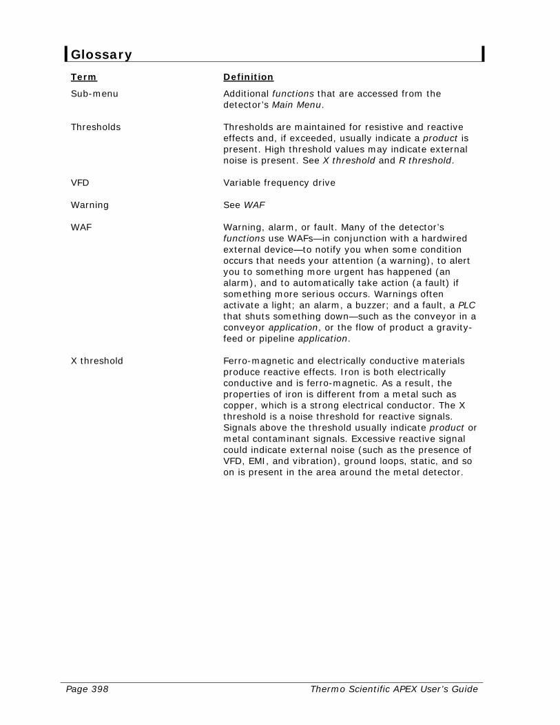
Page 398 Thermo Scientific APEX User’s Guide
Glossary Term Definition
Sub-menu Additional functions that are accessed from the detector’s Main Menu.
Thresholds Thresholds are maintained for resistive and reactive
effects and, if exceeded, usually indicate a product is present. High threshold values may indicate external noise is present. See X threshold and R threshold.
VFD Variable frequency drive Warning See WAF WAF Warning, alarm, or fault. Many of the detector’s
functions use WAFs—in conjunction with a hardwired external device—to notify you when some condition occurs that needs your attention (a warning), to alert you to something more urgent has happened (an alarm), and to automatically take action (a fault) if something more serious occurs. Warnings often activate a light; an alarm, a buzzer; and a fault, a PLC that shuts something down—such as the conveyor in a conveyor application, or the flow of product a gravity-feed or pipeline application.
X threshold Ferro-magnetic and electrically conductive materials
produce reactive effects. Iron is both electrically conductive and is ferro-magnetic. As a result, the properties of iron is different from a metal such as copper, which is a strong electrical conductor. The X threshold is a noise threshold for reactive signals. Signals above the threshold usually indicate product or metal contaminant signals. Excessive reactive signal could indicate external noise (such as the presence of VFD, EMI, and vibration), ground loops, static, and so on is present in the area around the metal detector.
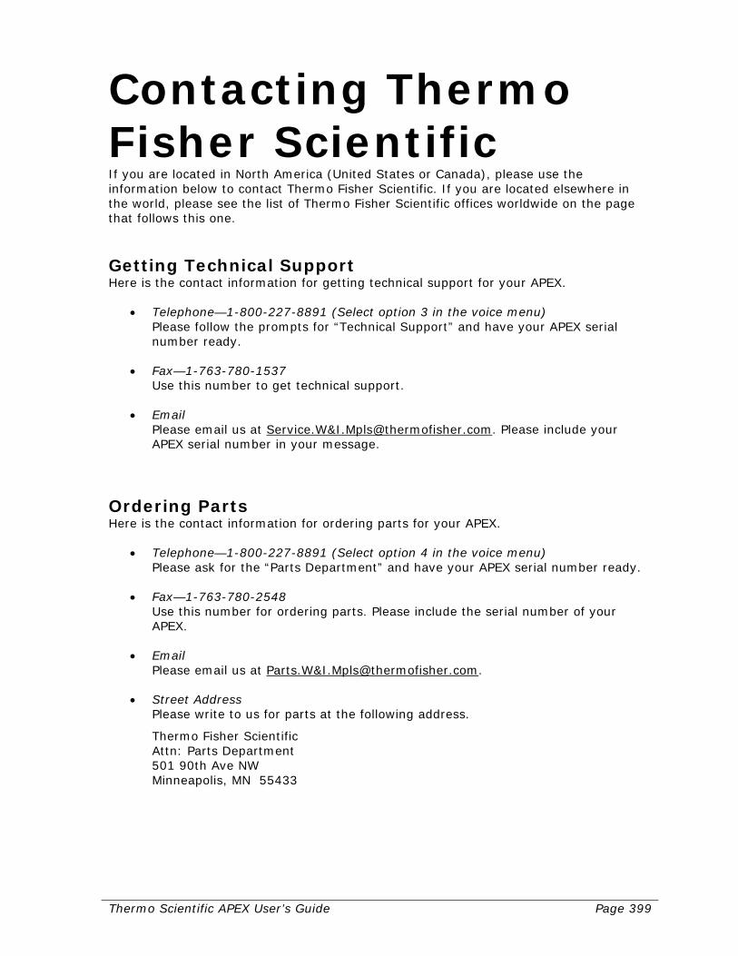
Thermo Scientific APEX User’s Guide Page 399
Contacting Thermo Fisher Scientific If you are located in North America (United States or Canada), please use the information below to contact Thermo Fisher Scientific. If you are located elsewhere in the world, please see the list of Thermo Fisher Scientific offices worldwide on the page that follows this one.
Getting Technical Support Here is the contact information for getting technical support for your APEX.
• Telephone—1-800-227-8891 (Select option 3 in the voice menu) Please follow the prompts for “Technical Support” and have your APEX serial number ready.
• Fax—1-763-780-1537 Use this number to get technical support.
• Email Please email us at Service.W&[email protected]. Please include your APEX serial number in your message.
Ordering Parts Here is the contact information for ordering parts for your APEX.
• Telephone—1-800-227-8891 (Select option 4 in the voice menu) Please ask for the “Parts Department” and have your APEX serial number ready.
• Fax—1-763-780-2548 Use this number for ordering parts. Please include the serial number of your APEX.
• Email Please email us at Parts.W&[email protected].
• Street Address Please write to us for parts at the following address.
Thermo Fisher Scientific Attn: Parts Department 501 90th Ave NW Minneapolis, MN 55433

Page 400 Thermo Scientific APEX User’s Guide
Obtaining a Return Materials Authorization Number Here is the contact information for getting an RMA number.
• Telephone—1-800-227-8891 Please press Option 3 (or state you need an “RMA number”).
• Fax—1-763-780-1537 Please complete the Return Material Authorization (RMA) form on page 266 of the manual. Then, fax it to us to get an RMA number.
• Email Please email the Service Department at Service.W&[email protected] and ask for an RMA number.

Thermo Scientific APEX User’s Guide Page 401
List of Thermo Fisher Scientific Offices Worldwide Asia/Pacific +86 21 6865 4588 +86 21 6445 1101 fax China +86 (800) 810 5118 +86 21 6445 1101 fax France +33 (0) 1 60 92 48 00 +33 (0) 1 60 92 49 00 fax Germany +49 (0) 208-824930 +49 (0) 208-852310 fax Italy +39 02-0521 78861 +39 02-0521 272914 fax Mexico/Latin America +52 (01) 55 5639 2360 +52 (01) 55 5639 2227 fax Netherlands +31 (0) 31 76 579 5555 +31 (0) 31 76 571 4958 fax South Africa +27 (0) 11-609-3101 +27 (0) 11-609-3110 fax Spain +34 914 845 965 +34 914 843 597 fax United Kingdom +44 (0) 1788-820300 +44 (0) 1788-820301 fax United States/Canada +1 (800) 227-8891 +1 (763) 780-1537 fax

Page 402 Thermo Scientific APEX User’s Guide
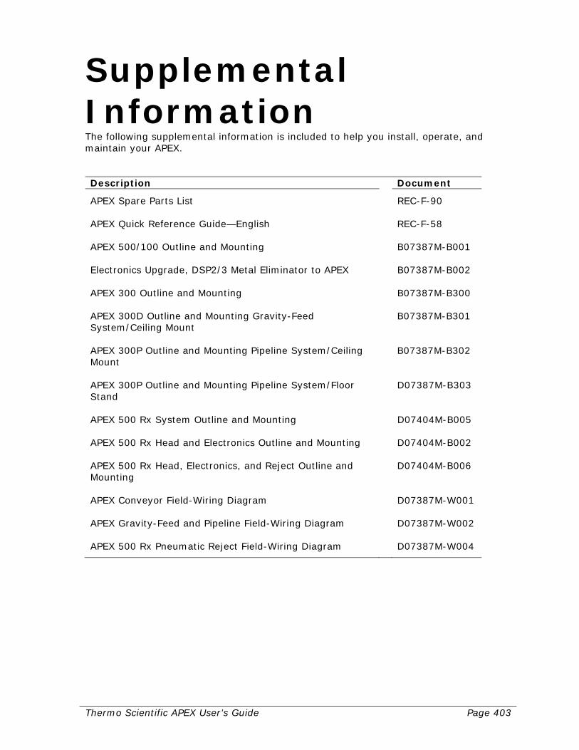
Thermo Scientific APEX User’s Guide Page 403
Supplemental Information The following supplemental information is included to help you install, operate, and maintain your APEX. Description Document
APEX Spare Parts List REC-F-90 APEX Quick Reference Guide—English REC-F-58 APEX 500/100 Outline and Mounting B07387M-B001 Electronics Upgrade, DSP2/3 Metal Eliminator to APEX B07387M-B002 APEX 300 Outline and Mounting B07387M-B300 APEX 300D Outline and Mounting Gravity-Feed System/Ceiling Mount
B07387M-B301
APEX 300P Outline and Mounting Pipeline System/Ceiling Mount
B07387M-B302
APEX 300P Outline and Mounting Pipeline System/Floor Stand
D07387M-B303
APEX 500 Rx System Outline and Mounting D07404M-B005 APEX 500 Rx Head and Electronics Outline and Mounting D07404M-B002 APEX 500 Rx Head, Electronics, and Reject Outline and Mounting
D07404M-B006
APEX Conveyor Field-Wiring Diagram D07387M-W001 APEX Gravity-Feed and Pipeline Field-Wiring Diagram D07387M-W002 APEX 500 Rx Pneumatic Reject Field-Wiring Diagram D07387M-W004

This page intentionally left blank
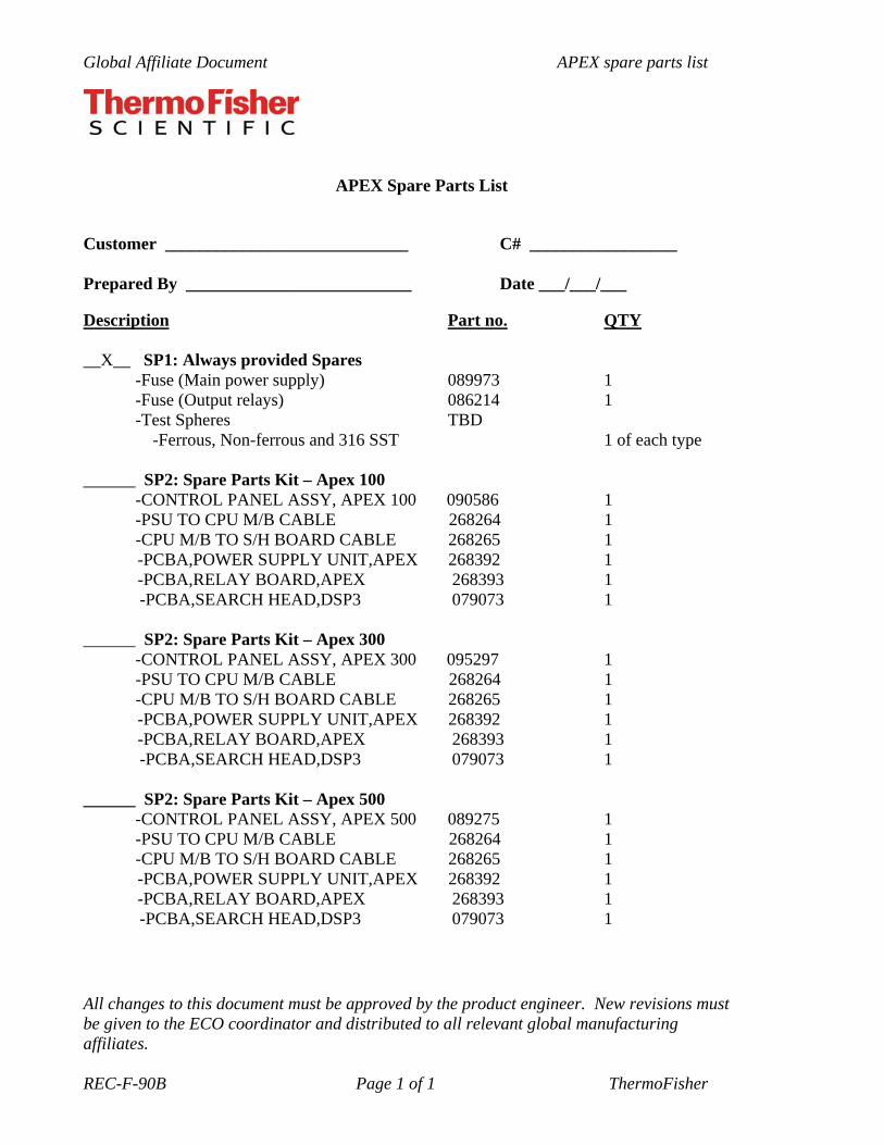
Global Affiliate Document APEX spare parts list
All changes to this document must be approved by the product engineer. New revisions must be given to the ECO coordinator and distributed to all relevant global manufacturing affiliates. REC-F-90B Page 1 of 1 ThermoFisher
APEX Spare Parts List
Customer ____________________________ C# _________________
Prepared By __________________________ Date ___/___/___
Description Part no. QTY __X__ SP1: Always provided Spares
-Fuse (Main power supply) 089973 1 -Fuse (Output relays) 086214 1 -Test Spheres TBD
-Ferrous, Non-ferrous and 316 SST 1 of each type
______ SP2: Spare Parts Kit – Apex 100 -CONTROL PANEL ASSY, APEX 100 090586 1 -PSU TO CPU M/B CABLE 268264 1 -CPU M/B TO S/H BOARD CABLE 268265 1 -PCBA,POWER SUPPLY UNIT,APEX 268392 1 -PCBA,RELAY BOARD,APEX 268393 1 -PCBA,SEARCH HEAD,DSP3 079073 1
______ SP2: Spare Parts Kit – Apex 300 -CONTROL PANEL ASSY, APEX 300 095297 1 -PSU TO CPU M/B CABLE 268264 1 -CPU M/B TO S/H BOARD CABLE 268265 1 -PCBA,POWER SUPPLY UNIT,APEX 268392 1 -PCBA,RELAY BOARD,APEX 268393 1 -PCBA,SEARCH HEAD,DSP3 079073 1
______ SP2: Spare Parts Kit – Apex 500 -CONTROL PANEL ASSY, APEX 500 089275 1 -PSU TO CPU M/B CABLE 268264 1 -CPU M/B TO S/H BOARD CABLE 268265 1 -PCBA,POWER SUPPLY UNIT,APEX 268392 1 -PCBA,RELAY BOARD,APEX 268393 1 -PCBA,SEARCH HEAD,DSP3 079073 1

This page intentionally left blank
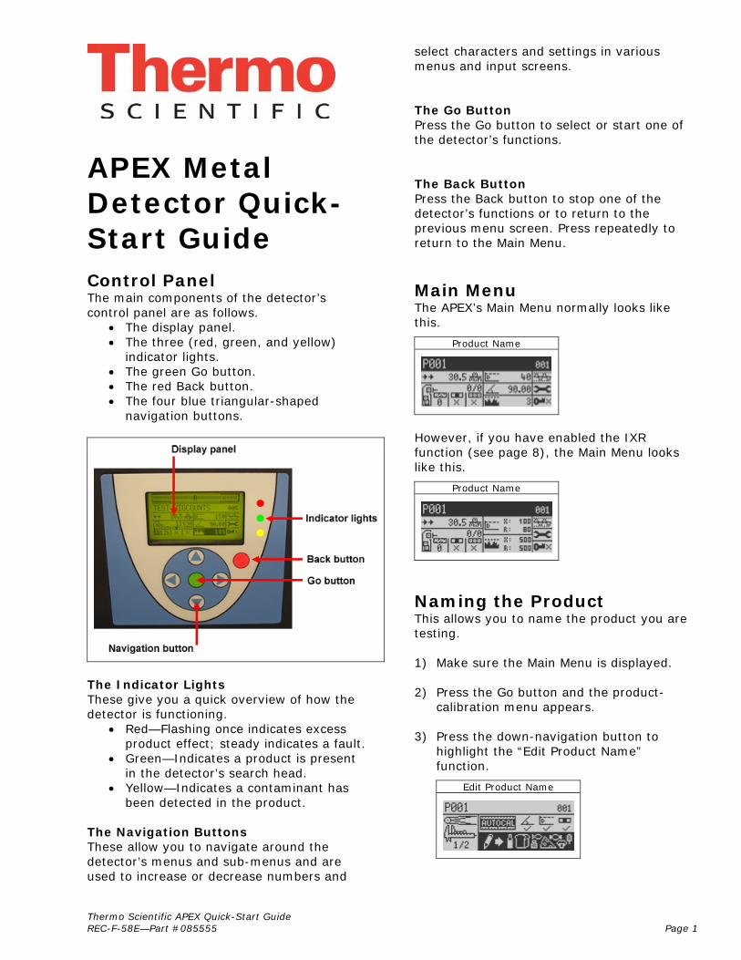
Thermo Scientific APEX Quick-Start Guide REC-F-58E—Part #085555 Page 1
APEX Metal Detector Quick-Start Guide
Control Panel The main components of the detector’s control panel are as follows.
• The display panel. • The three (red, green, and yellow)
indicator lights. • The green Go button. • The red Back button. • The four blue triangular-shaped
navigation buttons.
The Indicator Lights These give you a quick overview of how the detector is functioning.
• Red—Flashing once indicates excess product effect; steady indicates a fault.
• Green—Indicates a product is present in the detector’s search head.
• Yellow—Indicates a contaminant has been detected in the product.
The Navigation Buttons These allow you to navigate around the detector’s menus and sub-menus and are used to increase or decrease numbers and
select characters and settings in various menus and input screens. The Go Button Press the Go button to select or start one of the detector’s functions. The Back Button Press the Back button to stop one of the detector’s functions or to return to the previous menu screen. Press repeatedly to return to the Main Menu.
Main Menu The APEX’s Main Menu normally looks like this.
Product Name
However, if you have enabled the IXR function (see page 8), the Main Menu looks like this.
Product Name
Naming the Product This allows you to name the product you are testing. 1) Make sure the Main Menu is displayed. 2) Press the Go button and the product-
calibration menu appears. 3) Press the down-navigation button to
highlight the “Edit Product Name” function.
Edit Product Name
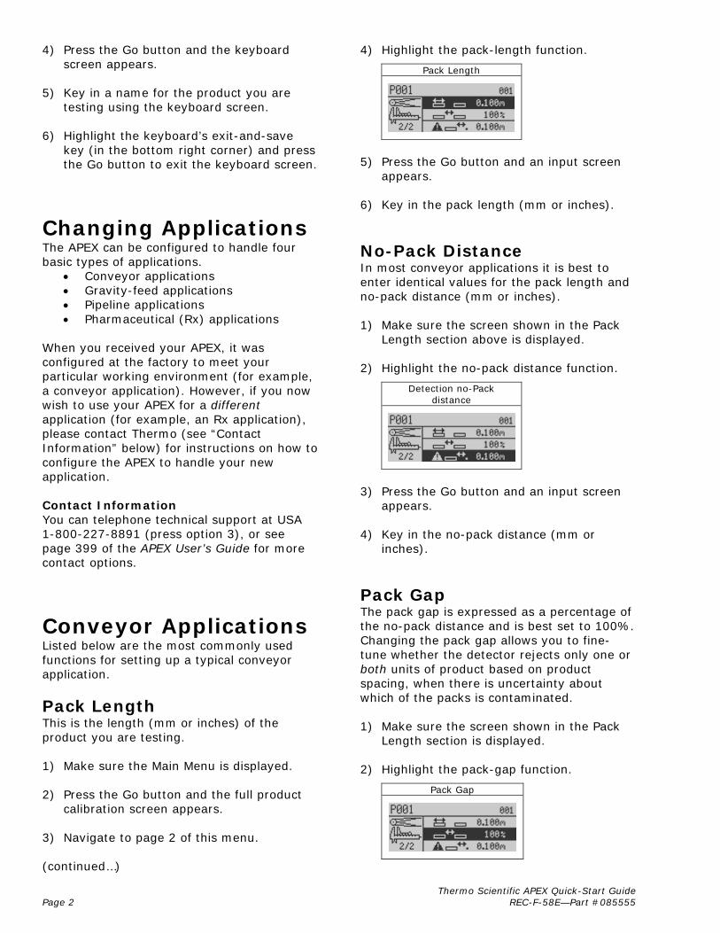
4) Press the Go button and the keyboard screen appears.
5) Key in a name for the product you are
testing using the keyboard screen. 6) Highlight the keyboard’s exit-and-save
key (in the bottom right corner) and press the Go button to exit the keyboard screen.
Thermo Scientific APEX Quick-Start Guide Page 2 REC-F-58E—Part #085555
Changing Applications The APEX can be configured to handle four basic types of applications.
• Conveyor applications • Gravity-feed applications • Pipeline applications • Pharmaceutical (Rx) applications
When you received your APEX, it was configured at the factory to meet your particular working environment (for example, a conveyor application). However, if you now wish to use your APEX for a different application (for example, an Rx application), please contact Thermo (see “Contact Information” below) for instructions on how to configure the APEX to handle your new application. Contact Information You can telephone technical support at USA 1-800-227-8891 (press option 3), or see page 399 of the APEX User’s Guide for more contact options.
Conveyor Applications Listed below are the most commonly used functions for setting up a typical conveyor application.
Pack Length This is the length (mm or inches) of the product you are testing. 1) Make sure the Main Menu is displayed. 2) Press the Go button and the full product
calibration screen appears. 3) Navigate to page 2 of this menu. (continued…)
4) Highlight the pack-length function.
Pack Length
5) Press the Go button and an input screen
appears. 6) Key in the pack length (mm or inches).
No-Pack Distance In most conveyor applications it is best to enter identical values for the pack length and no-pack distance (mm or inches). 1) Make sure the screen shown in the Pack
Length section above is displayed. 2) Highlight the no-pack distance function.
Detection no-Pack distance
3) Press the Go button and an input screen
appears. 4) Key in the no-pack distance (mm or
inches).
Pack Gap The pack gap is expressed as a percentage of the no-pack distance and is best set to 100%. Changing the pack gap allows you to fine-tune whether the detector rejects only one or both units of product based on product spacing, when there is uncertainty about which of the packs is contaminated. 1) Make sure the screen shown in the Pack
Length section is displayed. 2) Highlight the pack-gap function.
Pack Gap
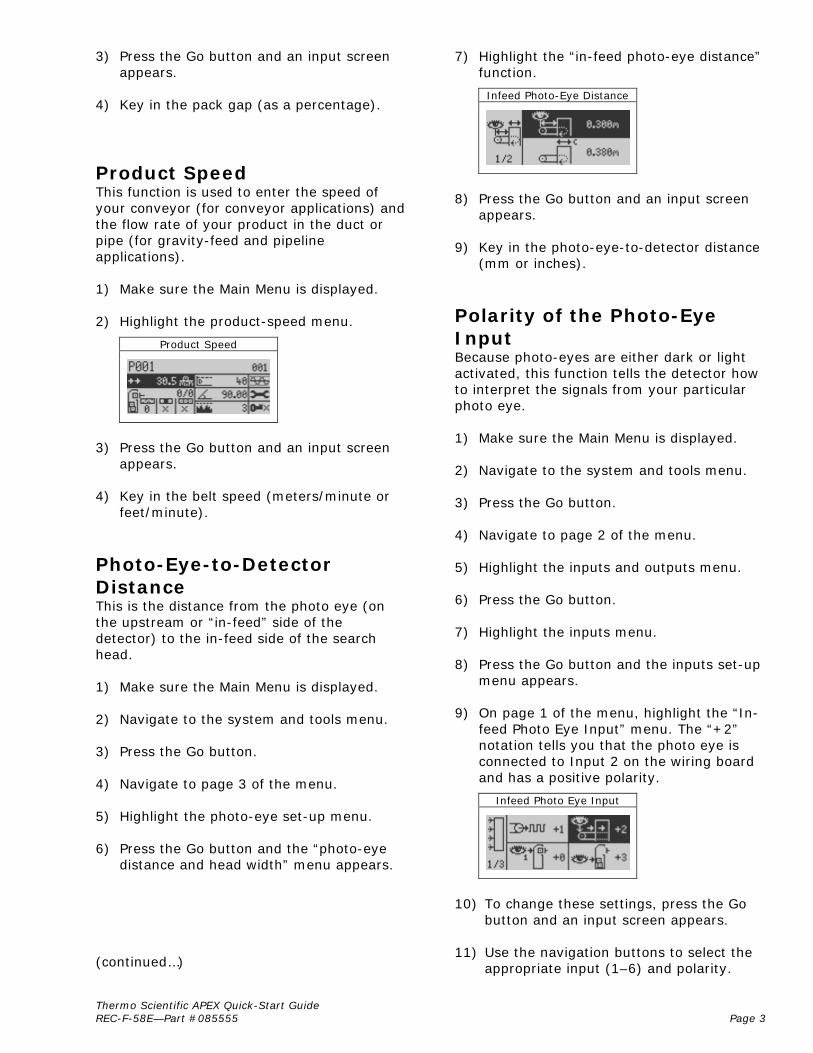
3) Press the Go button and an input screen appears.
4) Key in the pack gap (as a percentage).
Product Speed
Thermo Scientific APEX Quick-Start Guide REC-F-58E—Part #085555 Page 3
This function is used to enter the speed of your conveyor (for conveyor applications) and the flow rate of your product in the duct or pipe (for gravity-feed and pipeline applications). 1) Make sure the Main Menu is displayed. 2) Highlight the product-speed menu.
Product Speed
3) Press the Go button and an input screen
appears. 4) Key in the belt speed (meters/minute or
feet/minute).
Photo-Eye-to-Detector Distance This is the distance from the photo eye (on the upstream or “in-feed” side of the detector) to the in-feed side of the search head. 1) Make sure the Main Menu is displayed. 2) Navigate to the system and tools menu. 3) Press the Go button. 4) Navigate to page 3 of the menu. 5) Highlight the photo-eye set-up menu. 6) Press the Go button and the “photo-eye
distance and head width” menu appears. (continued…)
7) Highlight the “in-feed photo-eye distance” function.
Infeed Photo-Eye Distance
8) Press the Go button and an input screen
appears. 9) Key in the photo-eye-to-detector distance
(mm or inches).
Polarity of the Photo-Eye Input Because photo-eyes are either dark or light activated, this function tells the detector how to interpret the signals from your particular photo eye. 1) Make sure the Main Menu is displayed. 2) Navigate to the system and tools menu. 3) Press the Go button. 4) Navigate to page 2 of the menu. 5) Highlight the inputs and outputs menu. 6) Press the Go button. 7) Highlight the inputs menu. 8) Press the Go button and the inputs set-up
menu appears. 9) On page 1 of the menu, highlight the “In-
feed Photo Eye Input” menu. The “+2” notation tells you that the photo eye is connected to Input 2 on the wiring board and has a positive polarity.
Infeed Photo Eye Input
10) To change these settings, press the Go
button and an input screen appears. 11) Use the navigation buttons to select the
appropriate input (1–6) and polarity.

Photo Registration for Product Rejects This function allows you to select which part of the product triggers your reject device. This function is usually used for products that exceed six inches in length. Rejects are triggered in three different ways, as follows.
Thermo Scientific APEX Quick-Start Guide Page 4 REC-F-58E—Part #085555
• By the leading-edge of the product.
• By the center of the product.
• By the entire length of the product.
1) Make sure the Main Menu is displayed. 2) Highlight the rejects menu. 3) Press the Go button. 4) Navigate to page 2 of the menu. 5) Press the right-navigation button to select
the photo-registration menu.
Leading Photo Registration
6) To change this setting, press the Go
button repeatedly until a check mark appears beside the part of the product that will trigger your reject device.
Distance to the Reject Device This function allows you to input the distance (mm or inches) from the downstream edge of the search head to the center of your main (Reject 1) device. 1) Make sure the Main Menu is displayed. 2) Highlight the rejects menu. 3) Press the Go button. (continued…)
4) On page 1 of the rejects menu, highlight the “Reject 1 Distance/Delay” function.
Reject 1 Distance/Delay
5) Press the Go button an input-screen
appears. 6) Key in the appropriate distance (mm or
inches). If you want to set a delay time, first highlight the “m→s” (or “ft→s”) function, and press the Go button to select “delay” (a time parameter), which you will set in minutes and seconds in step 5 above.
Signal Duration for the Reject Device This function allows you to set the duration of the signal needed (expressed in seconds and hundredths of a second) to activate your Reject-1 device. 1) Make sure the screen shown in the
“Distance to the Reject Device” section above is displayed.
2) Highlight the “Reject 1 Duration” function.
Reject 1 Duration
3) Press the Go button and an input screen
appears. 4) Key in the appropriate duration time
(minutes and seconds). If you want to set the duration parameter as a distance, highlight the “s→m” (or “s→ft”) function, press the Go button to select a distance parameter, then go to step 3 above and key in a distance (mm or inches).
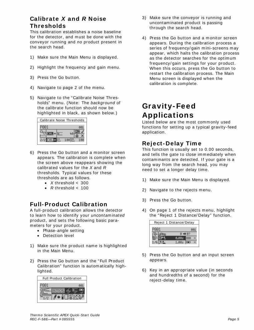
Calibrate X and R Noise Thresholds This calibration establishes a noise baseline for the detector, and must be done with the conveyor running and no product present in the search head. 1) Make sure the Main Menu is displayed. 2) Highlight the frequency and gain menu. 3) Press the Go button. 4) Navigate to page 2 of the menu. 5) Navigate to the “Calibrate Noise Thres-
holds” menu. (Note: The background of the calibrate function should now be highlighted in black, as shown below.)
Calibrate Noise Thresholds
Thermo Scientific APEX Quick-Start Guide REC-F-58E—Part #085555 Page 5
6) Press the Go button and a monitor screen
appears. The calibration is complete when the screen above reappears showing the calibrated values for the X and R thresholds. Typical values for these thresholds are as follows.
• X threshold < 300 • R threshold < 100
Full-Product Calibration A full-product calibration allows the detector to learn how to identify your uncontaminated product, and sets the following basic para-meters for your product.
• Phase-angle setting • Detection level
1) Make sure the product name is highlighted
in the Main Menu. 2) Press the Go button and the “Full Product
Calibration” function is automatically high-lighted.
Full Product Calibration
3) Make sure the conveyor is running and uncontaminated product is passing through the search head.
4) Press the Go button and a monitor screen
appears. During the calibration process a series of frequency/gain mini-screens may appear, which halts the calibration process as the detector searches for the optimum frequency/gain settings for your product. When this occurs, press the Go button to restart the calibration process. The Main Menu screen is displayed when the calibration is complete.
Gravity-Feed Applications Listed below are the most commonly used functions for setting up a typical gravity-feed application.
Reject-Delay Time This function is usually set to 0.00 seconds, and tells the gate to close immediately when contaminants are detected. If your gate is a long way from the search head, you may need to set a longer delay time. 1) Make sure the Main Menu is displayed. 2) Navigate to the rejects menu. 3) Press the Go button. 4) On page 1 of the rejects menu, highlight
the “Reject 1 Distance/Delay” function.
Reject 1 Distance/Delay
5) Press the Go button and an input screen
appears. 6) Key in an appropriate value (in seconds
and hundredths of a second) for the reject-delay time.
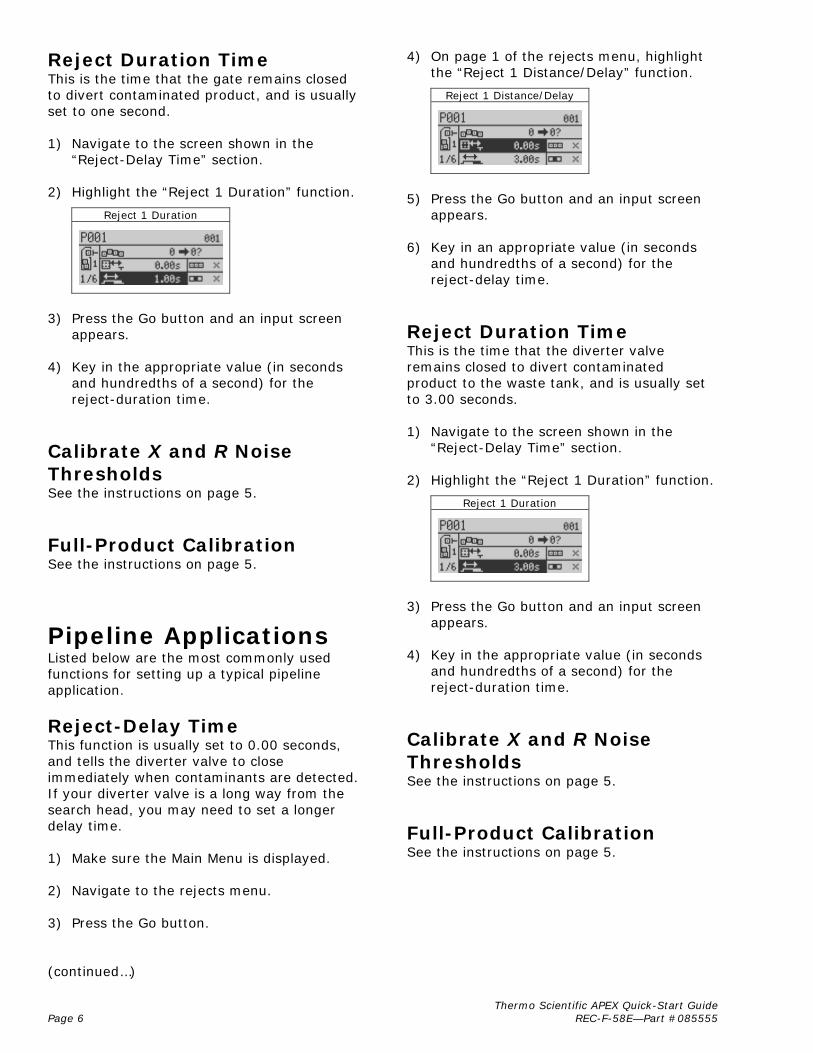
Reject Duration Time This is the time that the gate remains closed to divert contaminated product, and is usually set to one second. 1) Navigate to the screen shown in the
“Reject-Delay Time” section.
Thermo Scientific APEX Quick-Start Guide Page 6 REC-F-58E—Part #085555
2) Highlight the “Reject 1 Duration” function.
Reject 1 Duration
3) Press the Go button and an input screen
appears. 4) Key in the appropriate value (in seconds
and hundredths of a second) for the reject-duration time.
Calibrate X and R Noise Thresholds See the instructions on page 5.
Full-Product Calibration See the instructions on page 5.
Pipeline Applications Listed below are the most commonly used functions for setting up a typical pipeline application.
Reject-Delay Time This function is usually set to 0.00 seconds, and tells the diverter valve to close immediately when contaminants are detected. If your diverter valve is a long way from the search head, you may need to set a longer delay time. 1) Make sure the Main Menu is displayed. 2) Navigate to the rejects menu. 3) Press the Go button. (continued…)
4) On page 1 of the rejects menu, highlight the “Reject 1 Distance/Delay” function.
Reject 1 Distance/Delay
5) Press the Go button and an input screen
appears. 6) Key in an appropriate value (in seconds
and hundredths of a second) for the reject-delay time.
Reject Duration Time This is the time that the diverter valve remains closed to divert contaminated product to the waste tank, and is usually set to 3.00 seconds. 1) Navigate to the screen shown in the
“Reject-Delay Time” section. 2) Highlight the “Reject 1 Duration” function.
Reject 1 Duration
3) Press the Go button and an input screen
appears. 4) Key in the appropriate value (in seconds
and hundredths of a second) for the reject-duration time.
Calibrate X and R Noise Thresholds See the instructions on page 5.
Full-Product Calibration See the instructions on page 5.
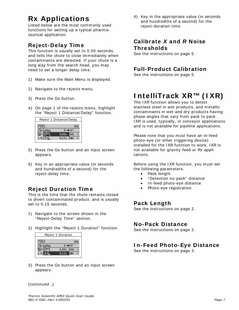
Rx Applications Listed below are the most commonly used functions for setting up a typical pharma-ceutical application.
Reject-Delay Time This function is usually set to 0.00 seconds, and tells the chute to close immediately when contaminants are detected. If your chute is a long way from the search head, you may need to set a longer delay time. 1) Make sure the Main Menu is displayed. 2) Navigate to the rejects menu. 3) Press the Go button. 4) On page 1 of the rejects menu, highlight
the “Reject 1 Distance/Delay” function.
Reject 1 Distance/Delay
Thermo Scientific APEX Quick-Start Guide REC-F-58E—Part #085555 Page 7
5) Press the Go button and an input screen
appears. 6) Key in an appropriate value (in seconds
and hundredths of a second) for the reject-delay time.
Reject Duration Time This is the time that the chute remains closed to divert contaminated product, and is usually set to 0.15 seconds. 1) Navigate to the screen shown in the
“Reject-Delay Time” section. 2) Highlight the “Reject 1 Duration” function.
Reject 1 Duration
3) Press the Go button and an input screen
appears. (continued…)
4) Key in the appropriate value (in seconds and hundredths of a second) for the reject-duration time.
Calibrate X and R Noise Thresholds See the instructions on page 5.
Full-Product Calibration See the instructions on page 5.
IntelliTrack XR™ (IXR) The IXR function allows you to detect stainless steel in wet products, and metallic contaminants in wet and dry products having phase angles that vary from pack to pack. IXR is used, typically, in conveyor applications and is not available for pipeline applications. Please note that you must have an in-feed photo-eye (or other triggering device) installed for the IXR function to work. IXR is not available for gravity-feed or Rx appli-cations. Before using the IXR function, you must set the following parameters.
• Pack length • “Detection no-pack” distance • In-feed photo-eye distance • Photo-eye registration
Pack Length See the instructions on page 2.
No-Pack Distance See the instructions on page 2.
In-Feed Photo-Eye Distance See the instructions on page 3.
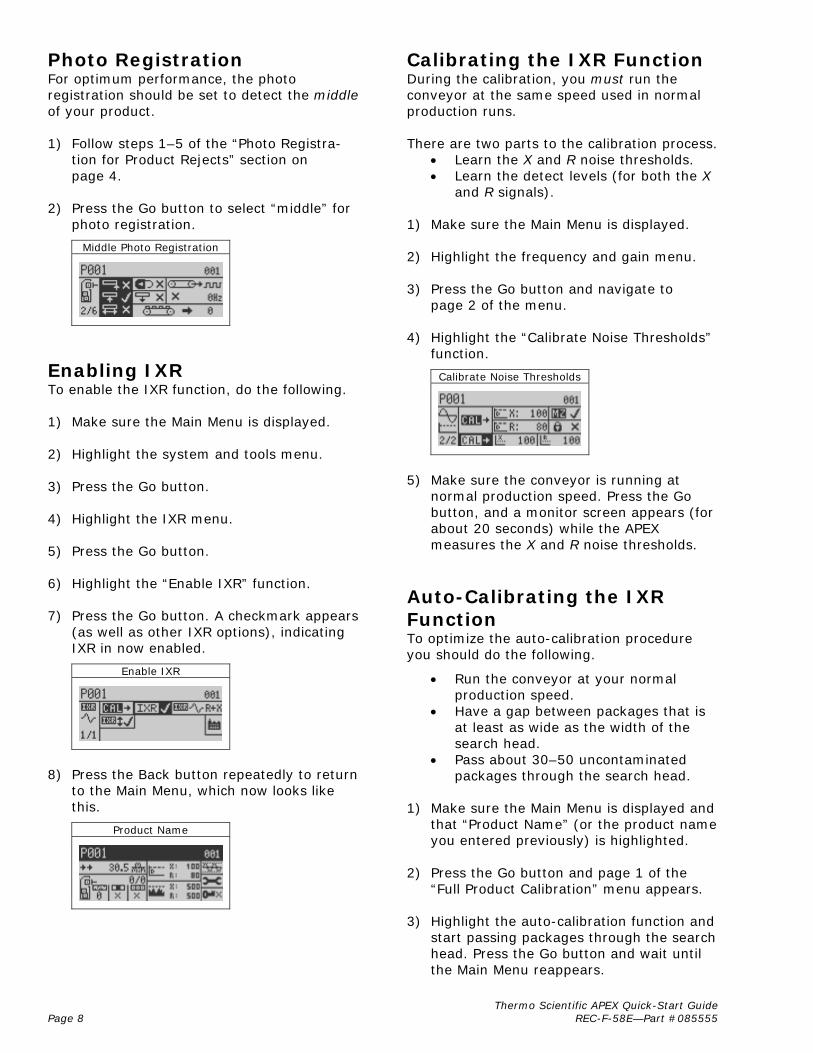
Photo Registration Calibrating the IXR Function For optimum performance, the photo registration should be set to detect the middle of your product.
During the calibration, you must run the conveyor at the same speed used in normal production runs.
1) Follow steps 1–5 of the “Photo Registra-
tion for Product Rejects” section on page 4.
There are two parts to the calibration process. • Learn the X and R noise thresholds. • Learn the detect levels (for both the X
and R signals). 2) Press the Go button to select “middle” for
photo registration.
1) Make sure the Main Menu is displayed. Middle Photo Registration
2) Highlight the frequency and gain menu. 3) Press the Go button and navigate to
page 2 of the menu.
4) Highlight the “Calibrate Noise Thresholds” function.
Enabling IXR Calibrate Noise Thresholds
To enable the IXR function, do the following. 1) Make sure the Main Menu is displayed. 2) Highlight the system and tools menu.
5) Make sure the conveyor is running at
normal production speed. Press the Go button, and a monitor screen appears (for about 20 seconds) while the APEX measures the X and R noise thresholds.
3) Press the Go button. 4) Highlight the IXR menu. 5) Press the Go button.
6) Highlight the “Enable IXR” function. Auto-Calibrating the IXR Function
7) Press the Go button. A checkmark appears
(as well as other IXR options), indicating IXR in now enabled.
To optimize the auto-calibration procedure you should do the following. Enable IXR
• Run the conveyor at your normal production speed.
• Have a gap between packages that is at least as wide as the width of the search head.
• Pass about 30–50 uncontaminated packages through the search head. 8) Press the Back button repeatedly to return
to the Main Menu, which now looks like this.
1) Make sure the Main Menu is displayed and
that “Product Name” (or the product name you entered previously) is highlighted.
Product Name
2) Press the Go button and page 1 of the
“Full Product Calibration” menu appears.
3) Highlight the auto-calibration function and start passing packages through the search head. Press the Go button and wait until the Main Menu reappears.
Thermo Scientific APEX Quick-Start Guide Page 8 REC-F-58E—Part #085555
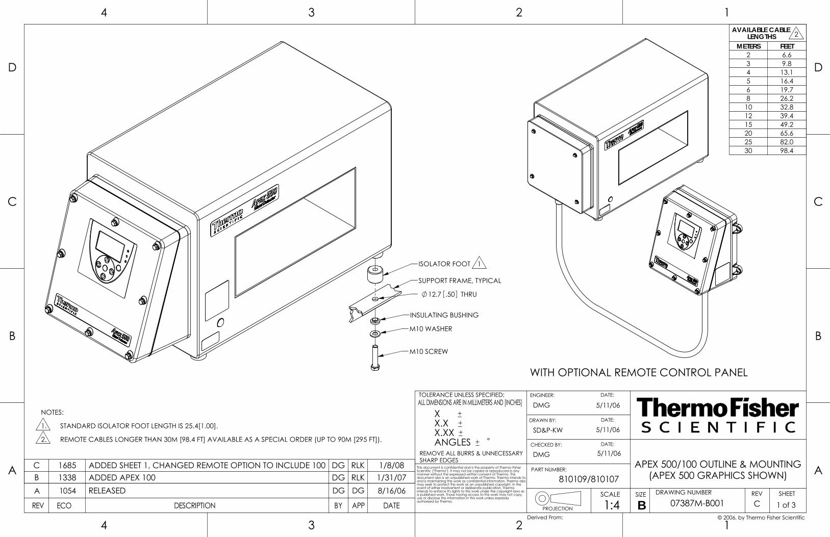
DRAWN BY:
CHECKED BY:
DATE:
3
3
B
A
4
C
D
4
B
PROJECTION
ALL DIMENSIONS ARE IN MILLIMETERS AND [INCHES]
REMOVE ALL BURRS & UNNECESSARYSHARP EDGES
PART NUMBER:
ENGINEER:
1
DRAWING NUMBERSIZESCALE
DATE:
SHEETREV
A
C
12
D
DATEAPPBYECO DESCRIPTION
2
TOLERANCE UNLESS SPECIFIED:
authorized by Thermo.REV
This document is confidential and is the property of Thermo Fisher Scientific ("Thermo"). It may not be copied or reproduced in any manner without the expressed written consent of Thermo. This document also is an unpublished work of Thermo. Thermo intends to and is maintaining the work as confidential information. Thermo also may seek to protect this work as an unpublished copyright. In the event of either inadvertent or deliberate publication, Thermo intends to enforce it's rights to this work under the copyright laws as a published work. Those having access to this work may not copy, use or disclose the information in this work unless expressly
DATE:
© 2006, by Thermo Fisher ScientificDerived From:
APEX 500/100 OUTLINE & MOUNTING
07387M-B001
(APEX 500 GRAPHICS SHOWN)
C 1 of 31:4
DMG 5/11/06
B1054 DG 8/16/06DGRELEASEDA
SD&P-KW
DMG
5/11/06
5/11/06
810109/810107
X X.X X.XX ANGLES
WITH OPTIONAL REMOTE CONTROL PANEL
M10 WASHER
M10 SCREW
ISOLATOR FOOT
SUPPORT FRAME, TYPICAL
INSULATING BUSHING
1
12.7 THRU.50
C 1685 ADDED SHEET 1, CHANGED REMOTE OPTION TO INCLUDE 100 DG RLKRLK1338 ADDED APEX 100 DG
STANDARD ISOLATOR FOOT LENGTH IS 25.4[1.00].1.
REMOTE CABLES LONGER THAN 30M [98.4 FT] AVAILABLE AS A SPECIAL ORDER (UP TO 90M [295 FT]).2.
2
1/31/071/8/08
B
NOTES:
AVAILABLE CABLE LENGTHS
METERS FEET2 6.63 9.84 13.15 16.46 19.78 26.210 32.812 39.415 49.220 65.625 82.030 98.4
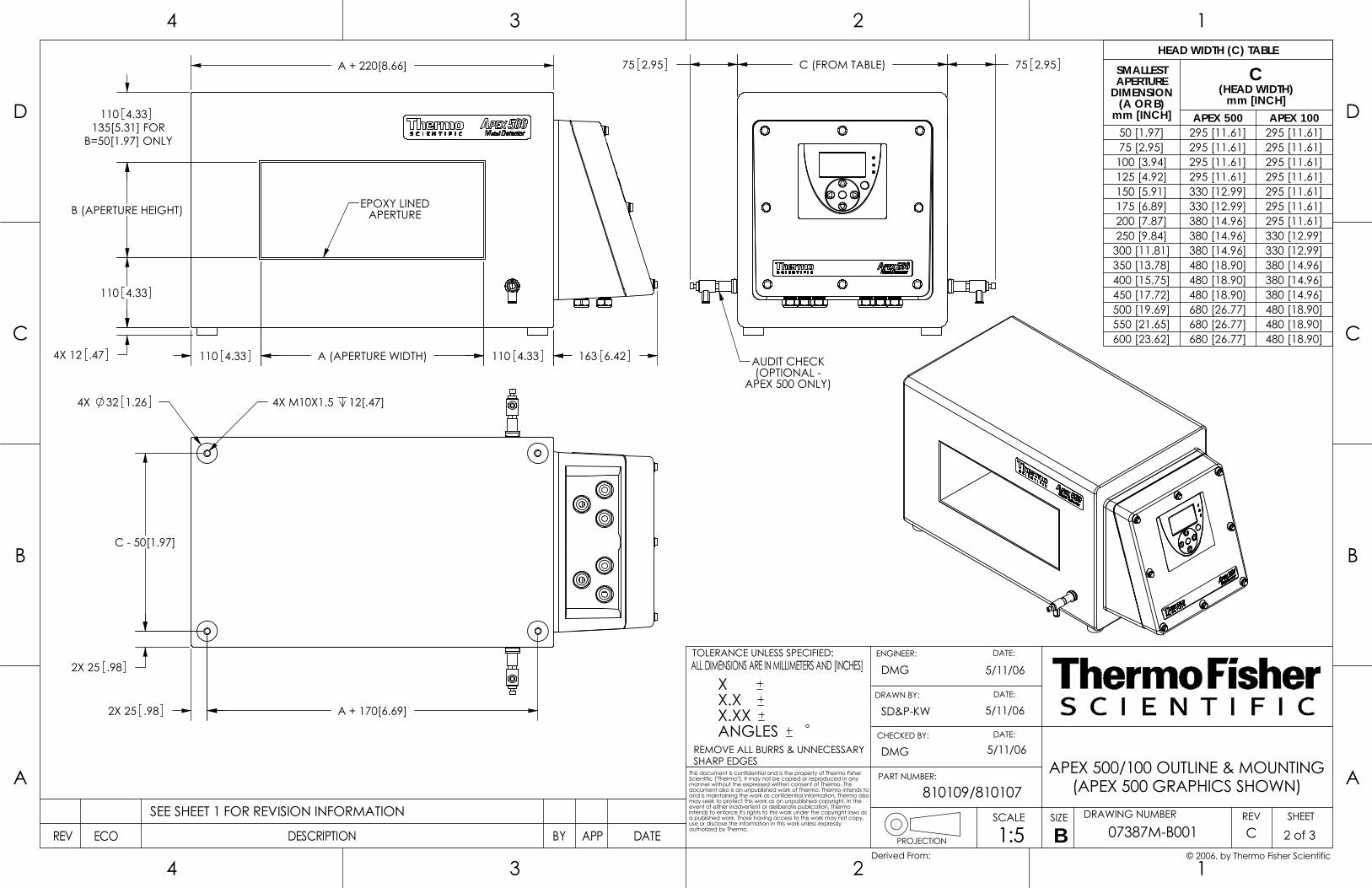
AUDIT CHECK(OPTIONAL -
APEX 500 ONLY)
C (FROM TABLE) 75 2.9575 2.95HEAD WIDTH (C) TABLE
SMALLESTAPERTURE
DIMENSION(A OR B)
mm [INCH]
C(HEAD WIDTH)
mm [INCH]APEX 500 APEX 100
50 [1.97] 295 [11.61] 295 [11.61]75 [2.95] 295 [11.61] 295 [11.61]100 [3.94] 295 [11.61] 295 [11.61]125 [4.92] 295 [11.61] 295 [11.61]150 [5.91] 330 [12.99] 295 [11.61]175 [6.89] 330 [12.99] 295 [11.61]200 [7.87] 380 [14.96] 295 [11.61]250 [9.84] 380 [14.96] 330 [12.99]300 [11.81] 380 [14.96] 330 [12.99]350 [13.78] 480 [18.90] 380 [14.96]400 [15.75] 480 [18.90] 380 [14.96]450 [17.72] 480 [18.90] 380 [14.96]500 [19.69] 680 [26.77] 480 [18.90]550 [21.65] 680 [26.77] 480 [18.90]600 [23.62] 680 [26.77] 480 [18.90]
DRAWN BY:
3
3
B
A
4
C
D
4
B
PROJECTION
2
REMOVE ALL BURRS & UNNECESSARYSHARP EDGES
PART NUMBER:
ENGINEER:
1
DRAWING NUMBERSIZESCALE
DATE:
SHEETREV
A
C
12
D
DATEAPPBYECO DESCRIPTIONREV
This document is confidential and is the property of Thermo Fisher Scientific ("Thermo"). It may not be copied or reproduced in any manner without the expressed written consent of Thermo. This document also is an unpublished work of Thermo. Thermo intends to and is maintaining the work as confidential information. Thermo also may seek to protect this work as an unpublished copyright. In the event of either inadvertent or deliberate publication, Thermo intends to enforce it's rights to this work under the copyright laws as a published work. Those having access to this work may not copy, use or disclose the information in this work unless expressly authorized by Thermo.
TOLERANCE UNLESS SPECIFIED:ALL DIMENSIONS ARE IN MILLIMETERS AND [INCHES]
CHECKED BY:
DATE:
DATE:
07387M-B001
APEX 500/100 OUTLINE & MOUNTING
(APEX 500 GRAPHICS SHOWN)
C 2 of 31:5
DMG 5/11/06
B SEE SHEET 1 FOR REVISION INFORMATION
SD&P-KW
DMG
5/11/06
5/11/06
810109/810107
© 2006, by Thermo Fisher ScientificDerived From:
X X.X X.XX ANGLES
C - 50[1.97]
A + 170[6.69]
2X 25 .98
4X 32 1.26 4X M10X1.5 12[.47]
2X 25 .98
EPOXY LINEDAPERTURE
A (APERTURE WIDTH)
B (APERTURE HEIGHT)
110 4.33
4X 12 .47
110 4.33135[5.31] FOR
B=50[1.97] ONLY
A + 220[8.66]
110 4.33110 4.33 163 6.42
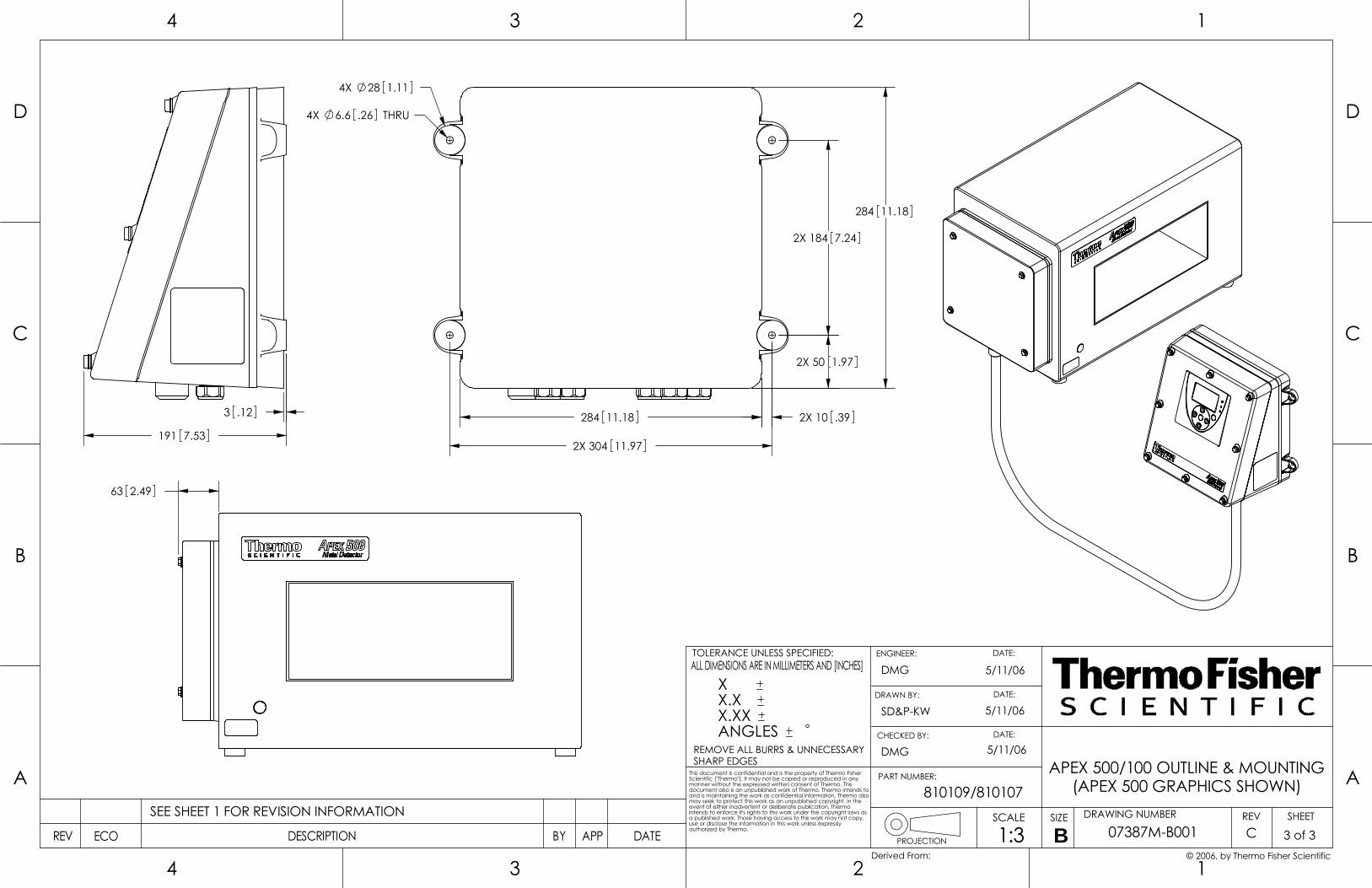
DRAWN BY:
3
3
B
A
4
C
D
4
B
PROJECTION
2
REMOVE ALL BURRS & UNNECESSARYSHARP EDGES
PART NUMBER:
ENGINEER:
1
DRAWING NUMBERSIZESCALE
DATE:
SHEETREV
A
C
12
D
DATEAPPBYECO DESCRIPTIONREV
This document is confidential and is the property of Thermo Fisher Scientific ("Thermo"). It may not be copied or reproduced in any manner without the expressed written consent of Thermo. This document also is an unpublished work of Thermo. Thermo intends to and is maintaining the work as confidential information. Thermo also may seek to protect this work as an unpublished copyright. In the event of either inadvertent or deliberate publication, Thermo intends to enforce it's rights to this work under the copyright laws as a published work. Those having access to this work may not copy, use or disclose the information in this work unless expressly authorized by Thermo.
TOLERANCE UNLESS SPECIFIED:ALL DIMENSIONS ARE IN MILLIMETERS AND [INCHES]
CHECKED BY:
DATE:
DATE:
07387M-B001
APEX 500/100 OUTLINE & MOUNTING
(APEX 500 GRAPHICS SHOWN)
C 3 of 31:3
DMG 5/11/06
B SEE SHEET 1 FOR REVISION INFORMATION
SD&P-KW
DMG
5/11/06
5/11/06
810109/810107
© 2006, by Thermo Fisher ScientificDerived From:
X X.X X.XX ANGLES
191 7.53
3 .12
63 2.49
2X 304 11.97
2X 184 7.24
284 11.18
2X 50 1.97
2X 10 .39284 11.18
4X 6.6 THRU.26
4X 28 1.11
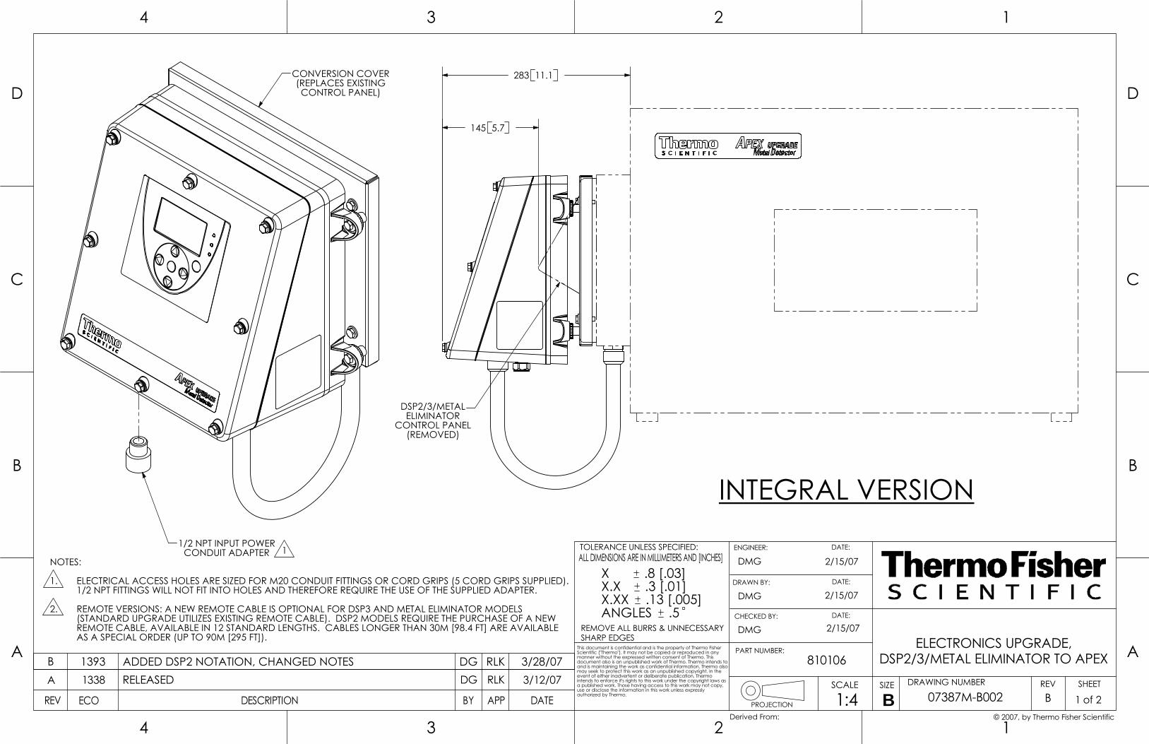
DSP2/3/METALELIMINATOR
CONTROL PANEL(REMOVED)
145 5.7
283 11.1
CHECKED BY:
DATE:
3
3
B
A
4
C
D
4
B
PROJECTION
ALL DIMENSIONS ARE IN MILLIMETERS AND [INCHES]
REMOVE ALL BURRS & UNNECESSARYSHARP EDGES
PART NUMBER:
ENGINEER:
1
DRAWING NUMBERSIZESCALE
DATE:
SHEETREV
A
C
12
D
DATEAPPBYECO DESCRIPTION
2
TOLERANCE UNLESS SPECIFIED:
authorized by Thermo.REV
This document is confidential and is the property of Thermo Fisher Scientific ("Thermo"). It may not be copied or reproduced in any manner without the expressed written consent of Thermo. This document also is an unpublished work of Thermo. Thermo intends to and is maintaining the work as confidential information. Thermo also may seek to protect this work as an unpublished copyright. In the event of either inadvertent or deliberate publication, Thermo intends to enforce it's rights to this work under the copyright laws as a published work. Those having access to this work may not copy, use or disclose the information in this work unless expressly
DATE:
Derived From: © 2007, by Thermo Fisher Scientific
ELECTRONICS UPGRADE,
1 of 2B1:4 07387M-B002
DSP2/3/METAL ELIMINATOR TO APEXRLK
DMG
B1338 DG
2/15/07
3/12/07
DMG
RELEASED
2/15/07DMG
A
2/15/07
810106
X .8 [.03]X.X .3 [.01]X.XX .13 [.005]ANGLES .5
DRAWN BY:
REMOTE VERSIONS: A NEW REMOTE CABLE IS OPTIONAL FOR DSP3 AND METAL ELIMINATOR MODELS
1/2 NPT FITTINGS WILL NOT FIT INTO HOLES AND THEREFORE REQUIRE THE USE OF THE SUPPLIED ADAPTER.
AS A SPECIAL ORDER (UP TO 90M [295 FT]).REMOTE CABLE, AVAILABLE IN 12 STANDARD LENGTHS. CABLES LONGER THAN 30M [98.4 FT] ARE AVAILABLE (STANDARD UPGRADE UTILIZES EXISTING REMOTE CABLE). DSP2 MODELS REQUIRE THE PURCHASE OF A NEW
INTEGRAL VERSION
2.
NOTES:
ELECTRICAL ACCESS HOLES ARE SIZED FOR M20 CONDUIT FITTINGS OR CORD GRIPS (5 CORD GRIPS SUPPLIED). 1.
B 1393 ADDED DSP2 NOTATION, CHANGED NOTES DG RLK 3/28/07
1/2 NPT INPUT POWERCONDUIT ADAPTER 1
CONVERSION COVER(REPLACES EXISTINGCONTROL PANEL)

191 7.53
3 .12
1/2 NPT INPUT POWERCONDUIT ADAPTER 1
MINITEK CABLEADAPTER, M16(SUPPLIED WITH
NEW CABLE)
REMOTE CABLE
3
3
B
A
4
C
D
4
B
PROJECTION
2
REMOVE ALL BURRS & UNNECESSARYSHARP EDGES
PART NUMBER:
ENGINEER:
1
DRAWING NUMBERSIZESCALE
DATE:
SHEETREV
A
C
12
D
DATEAPPBYECO DESCRIPTIONREV
This document is confidential and is the property of Thermo Fisher Scientific ("Thermo"). It may not be copied or reproduced in any manner without the expressed written consent of Thermo. This document also is an unpublished work of Thermo. Thermo intends to and is maintaining the work as confidential information. Thermo also may seek to protect this work as an unpublished copyright. In the event of either inadvertent or deliberate publication, Thermo intends to enforce it's rights to this work under the copyright laws as a published work. Those having access to this work may not copy, use or disclose the information in this work unless expressly authorized by Thermo.
TOLERANCE UNLESS SPECIFIED:ALL DIMENSIONS ARE IN MILLIMETERS AND [INCHES]
CHECKED BY:
DATE:
DATE:
07387M-B002
ELECTRONICS UPGRADE,
DSP2/3/METAL ELIMINATOR TO APEX
B 2 of 21:3
DMG 2/15/07
B SEE SHEET 1 FOR REVISION INFORMATION
DMG
DMG
2/15/07
2/15/07
810106
© 2007, by Thermo Fisher ScientificDerived From:
X .8 [.03]X.X .3 [.01]X.XX .13 [.005]ANGLES .5
DRAWN BY:
REMOTE VERSION
2
2
AVAILABLE CABLE LENGTHS METERS FEET
2 6.63 9.84 13.15 16.46 19.78 26.210 32.812 39.415 49.220 65.625 82.030 98.4
304 11.97
2X 7.24184
.26 THRU6.6
4X 1.1128
11.18284
4X 2X
284 11.18

CABLES LONGER THAN 30M [98.4 FT] AVAILABLE AS A SPECIAL ORDER (UP TO 90M [295 FT]).1.
STANDARD ISOLATOR FOOT LENGTH IS 25.4[1.00].2.
1
NOTES:
AVAILABLE CABLE LENGTHS METERS FEET
.5 1.62 6.63 9.84 13.15 16.46 19.78 26.210 32.812 39.415 49.220 65.625 82.030 98.4
CHECKED BY:
DATE:
3
3
B
A
4
C
D
4
B
PROJECTION
ALL DIMENSIONS ARE IN MILLIMETERS AND [INCHES]
REMOVE ALL BURRS & UNNECESSARYSHARP EDGES
PART NUMBER:
ENGINEER:
1
DRAWING NUMBERSIZESCALE
DATE:
SHEETREV
A
C
12
D
DATEAPPBYECO DESCRIPTION
2
TOLERANCE UNLESS SPECIFIED:
authorized by Thermo.REV
This document is confidential and is the property of Thermo Fisher Scientific ("Thermo"). It may not be copied or reproduced in any manner without the expressed written consent of Thermo. This document also is an unpublished work of Thermo. Thermo intends to and is maintaining the work as confidential information. Thermo also may seek to protect this work as an unpublished copyright. In the event of either inadvertent or deliberate publication, Thermo intends to enforce it's rights to this work under the copyright laws as a published work. Those having access to this work may not copy, use or disclose the information in this work unless expressly
DATE:
Derived From:
APEX 300 OUTLINE AND MOUNTING
07387M-B300
A 1 of 51:3
DMG 5/31/07
B1423 RLK 12/21/07DGRELEASEDA
DMG
DMG
5/31/07
5/31/07
810108
© 2007, by Thermo Fisher Scientific
X X.X X.XX ANGLES
DRAWN BY:
M10 WASHER
M10 SCREW
SHEET 2)
ISOLATOR FOOT 2
INSULATING BUSHING
DIMENSIONS
AUDIT CHECK(OPTIONAL,
SUPPORT FRAME, TYPICAL
12.7[.50] THRU

250[9.84]
C(HEAD WIDTH)
145[5.71]OR
75[2.95]
75[2.95]
4X 32 1.26 4X M10X1.5 12[.47]
A + 100[3.94] 2X 25 .98
2X D
2X E
(E)
PORTCABLE
EPOXY LINEDAPERTURE
A (APERTURE WIDTH)
(APERTURE HEIGHT)B
75 2.95
75 2.95100 [3.94] FOR B=50 ONLY
75 2.95155 6.09
A + 230[9.06]
4X 12 .4750 1.97 50 1.97
AUDIT CHECK(OPTIONAL)
3
3
B
A
4
C
D
4
B
PROJECTION
2
REMOVE ALL BURRS & UNNECESSARYSHARP EDGES
PART NUMBER:
ENGINEER:
1
DRAWING NUMBERSIZESCALE
DATE:
SHEETREV
A
C
12
D
DATEAPPBYECO DESCRIPTIONREV
This document is confidential and is the property of Thermo Fisher Scientific ("Thermo"). It may not be copied or reproduced in any manner without the expressed written consent of Thermo. This document also is an unpublished work of Thermo. Thermo intends to and is maintaining the work as confidential information. Thermo also may seek to protect this work as an unpublished copyright. In the event of either inadvertent or deliberate publication, Thermo intends to enforce it's rights to this work under the copyright laws as a published work. Those having access to this work may not copy, use or disclose the information in this work unless expressly authorized by Thermo.
TOLERANCE UNLESS SPECIFIED:ALL DIMENSIONS ARE IN MILLIMETERS AND [INCHES]
CHECKED BY:
DATE:
DATE:
07387M-B300
APEX 300 OUTLINE AND MOUNTING
A 2 of 51:3
DMG 5/31/07
B SEE SHEET 1 FOR REVISION INFORMATION
DMG
DMG
5/31/07
5/31/07
810108
© 2007, by Thermo Fisher ScientificDerived From:
X X.X X.XX ANGLES
DRAWN BY:
HORIZONTAL APERTUREHORIZONTAL PRODUCT FLOW
FOOT DIMENSION TABLEC
mm[INCH]D
mm[INCH]E
mm[INCH]145[5.71] 100[3.94] 22.5[.89]250[9.84] 200[7.87] 25[.98]
SQUARE APERTURE HEADSA & B (mm) C (mm)
75 145 OR 250100 145 OR 250125 145 OR 250150 145 OR 250175 145 OR 250200 145 OR 250225 145 OR 250250 145 OR 250
RECTANGULAR APERTURE HEADS: C (HEAD WIDTH, mm)B (APERTUREHEIGHT, mm)
A (APERTURE WIDTH, mm)100 150 200 250 300 350 400 450 500 550
50 145 145 145 145 145 145 145 145 145 14575 145 145 145 145 145 145 145 145 145 145
100 145 145 145 145 145 145 145 145 145125 145 145 145 145 145 145 145 145 145150 145 OR 250 145 OR 250 145 OR 250 145 OR 250 145 OR 250 145 OR 250 145 OR 250 145 OR 250175 145 OR 250 145 OR 250 145 OR 250 145 OR 250 145 OR 250 145 OR 250 145 OR 250 145 OR 250200 145 OR 250 145 OR 250 145 OR 250 145 OR 250 145 OR 250 145 OR 250 145 OR 250225 145 OR 250 145 OR 250 145 OR 250 145 OR 250 145 OR 250 145 OR 250 145 OR 250250 145 OR 250 145 OR 250 145 OR 250 145 OR 250 145 OR 250 145 OR 250
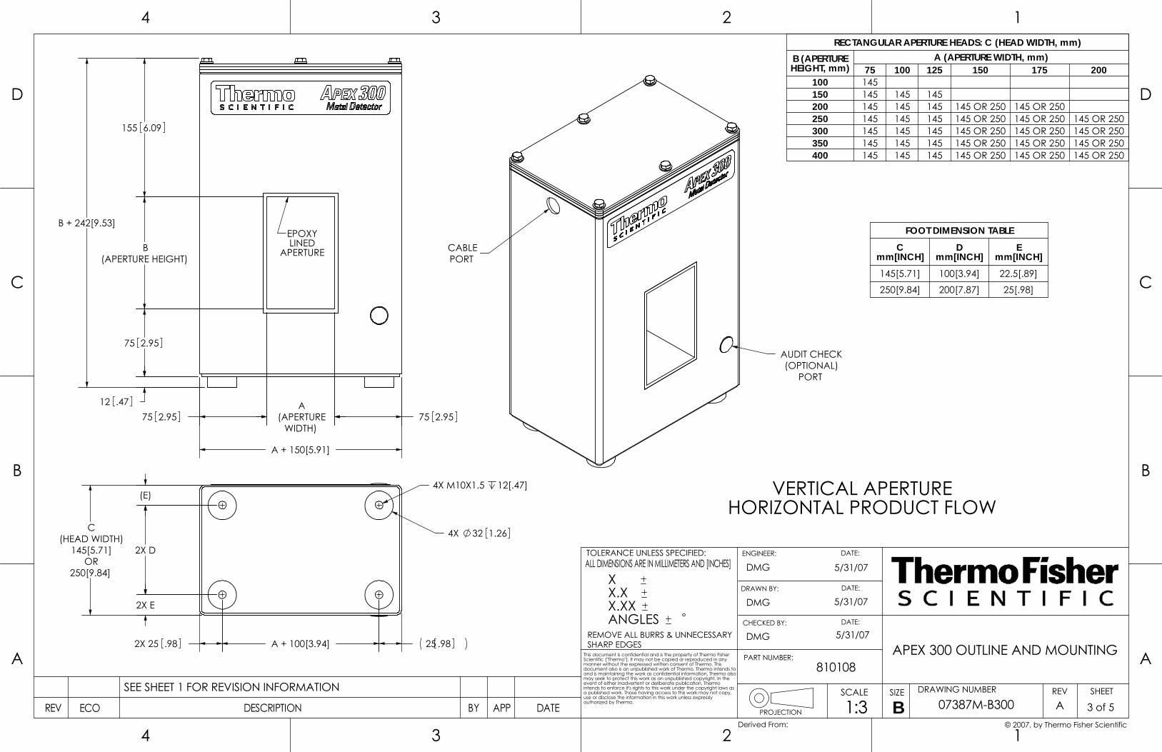
EPOXYLINED
APERTURE
75 2.95
(APERTURE HEIGHT)B
155 6.09
12 .47
WIDTH)
A(APERTURE75 2.95 75 2.95
A + 150[5.91]
B + 242[9.53]
(E)
2X D
2X E
250[9.84]
C(HEAD WIDTH)
145[5.71]OR
2X 25 .98 A + 100[3.94] 25 .98
4X 32 1.26
4X M10X1.5 12[.47] VERTICAL APERTUREHORIZONTAL PRODUCT FLOW
FOOT DIMENSION TABLEC
mm[INCH]D
mm[INCH]E
mm[INCH]145[5.71] 100[3.94] 22.5[.89]
250[9.84] 200[7.87] 25[.98]
RECTANGULAR APERTURE HEADS: C (HEAD WIDTH, mm)B (APERTUREHEIGHT, mm)
A (APERTURE WIDTH, mm)75 100 125 150 175 200
100 145150 145 145 145200 145 145 145 145 OR 250 145 OR 250250 145 145 145 145 OR 250 145 OR 250 145 OR 250300 145 145 145 145 OR 250 145 OR 250 145 OR 250350 145 145 145 145 OR 250 145 OR 250 145 OR 250400 145 145 145 145 OR 250 145 OR 250 145 OR 250
3
3
B
A
4
C
D
4
B
PROJECTION
2
REMOVE ALL BURRS & UNNECESSARYSHARP EDGES
PART NUMBER:
ENGINEER:
1
DRAWING NUMBERSIZESCALE
DATE:
SHEETREV
A
C
12
D
DATEAPPBYECO DESCRIPTIONREV
This document is confidential and is the property of Thermo Fisher Scientific ("Thermo"). It may not be copied or reproduced in any manner without the expressed written consent of Thermo. This document also is an unpublished work of Thermo. Thermo intends to and is maintaining the work as confidential information. Thermo also may seek to protect this work as an unpublished copyright. In the event of either inadvertent or deliberate publication, Thermo intends to enforce it's rights to this work under the copyright laws as a published work. Those having access to this work may not copy, use or disclose the information in this work unless expressly authorized by Thermo.
TOLERANCE UNLESS SPECIFIED:ALL DIMENSIONS ARE IN MILLIMETERS AND [INCHES]
CHECKED BY:
DATE:
DATE:
07387M-B300
APEX 300 OUTLINE AND MOUNTING
A 3 of 51:3
DMG 5/31/07
B SEE SHEET 1 FOR REVISION INFORMATION
DMG
DMG
5/31/07
5/31/07
810108
© 2007, by Thermo Fisher ScientificDerived From:
X X.X X.XX ANGLES
DRAWN BY:
PORTCABLE
PORT
AUDIT CHECK(OPTIONAL)
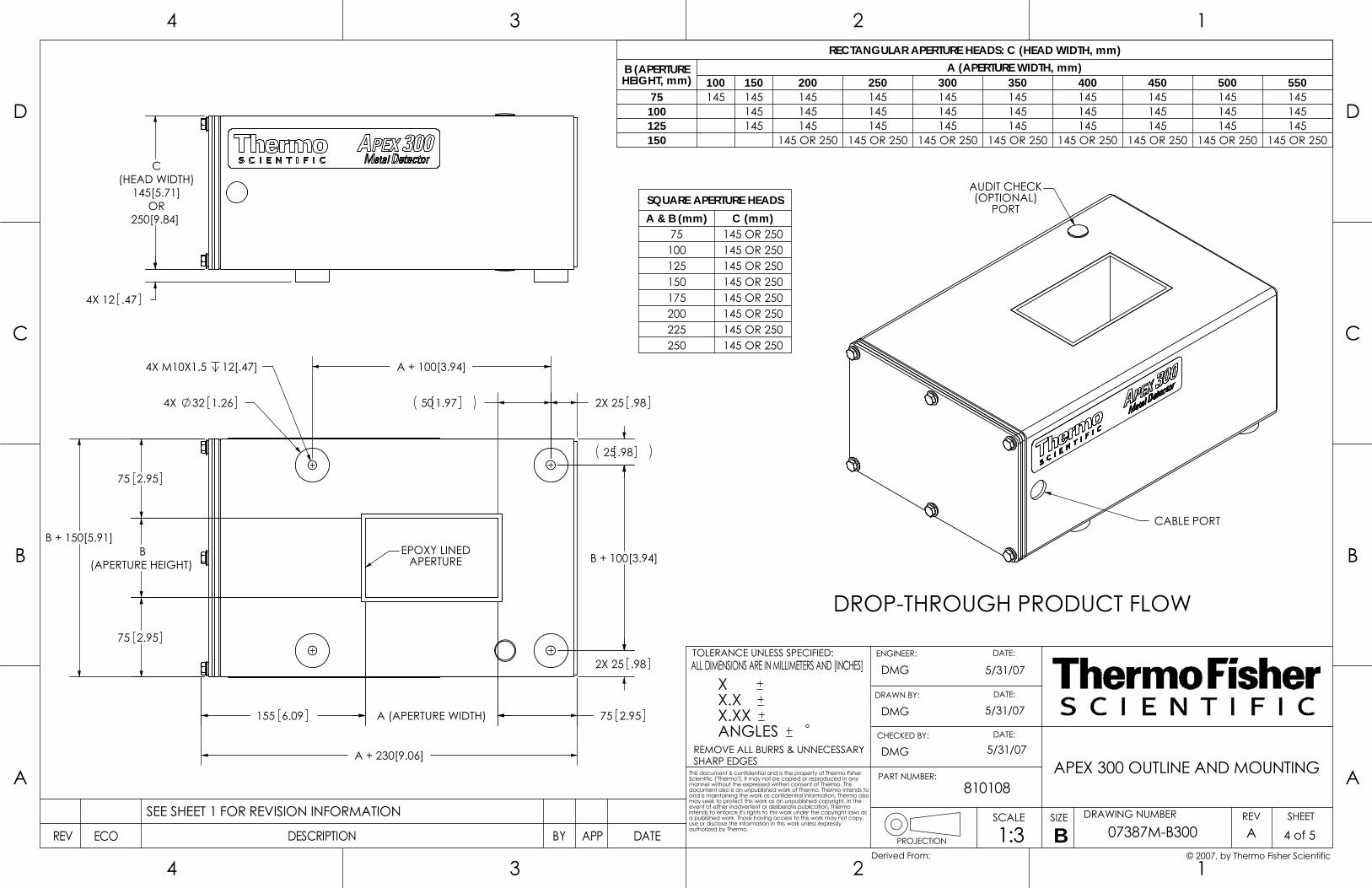
250[9.84]
C(HEAD WIDTH)
145[5.71]OR
4X 12 .47
3
3
B
A
4
C
D
4
B
PROJECTION
2
REMOVE ALL BURRS & UNNECESSARYSHARP EDGES
PART NUMBER:
ENGINEER:
1
DRAWING NUMBERSIZESCALE
DATE:
SHEETREV
A
C
12
D
DATEAPPBYECO DESCRIPTIONREV
This document is confidential and is the property of Thermo Fisher Scientific ("Thermo"). It may not be copied or reproduced in any manner without the expressed written consent of Thermo. This document also is an unpublished work of Thermo. Thermo intends to and is maintaining the work as confidential information. Thermo also may seek to protect this work as an unpublished copyright. In the event of either inadvertent or deliberate publication, Thermo intends to enforce it's rights to this work under the copyright laws as a published work. Those having access to this work may not copy, use or disclose the information in this work unless expressly authorized by Thermo.
TOLERANCE UNLESS SPECIFIED:ALL DIMENSIONS ARE IN MILLIMETERS AND [INCHES]
CHECKED BY:
DATE:
DATE:
07387M-B300
APEX 300 OUTLINE AND MOUNTING
A 4 of 51:3
DMG 5/31/07
B SEE SHEET 1 FOR REVISION INFORMATION
DMG
DMG
5/31/07
5/31/07
810108
© 2007, by Thermo Fisher ScientificDerived From:
X X.X X.XX ANGLES
DRAWN BY:
EPOXY LINEDAPERTURE(APERTURE HEIGHT)
B
75 2.95
75 2.95
B + 150[5.91]
A (APERTURE WIDTH) 75 2.95155 6.09
A + 230[9.06]
2X 25 .98
B + 100[3.94]
25 .98
2X 25 .98
A + 100[3.94]
50 1.974X 32 1.26
4X M10X1.5 12[.47]
AUDIT CHECK(OPTIONAL)
PORT
CABLE PORT
DROP-THROUGH PRODUCT FLOW
RECTANGULAR APERTURE HEADS: C (HEAD WIDTH, mm)B (APERTUREHEIGHT, mm)
A (APERTURE WIDTH, mm)100 150 200 250 300 350 400 450 500 550
75 145 145 145 145 145 145 145 145 145 145100 145 145 145 145 145 145 145 145 145125 145 145 145 145 145 145 145 145 145150 145 OR 250 145 OR 250 145 OR 250 145 OR 250 145 OR 250 145 OR 250 145 OR 250 145 OR 250
SQUARE APERTURE HEADSA & B (mm) C (mm)
75 145 OR 250100 145 OR 250125 145 OR 250150 145 OR 250175 145 OR 250200 145 OR 250225 145 OR 250250 145 OR 250
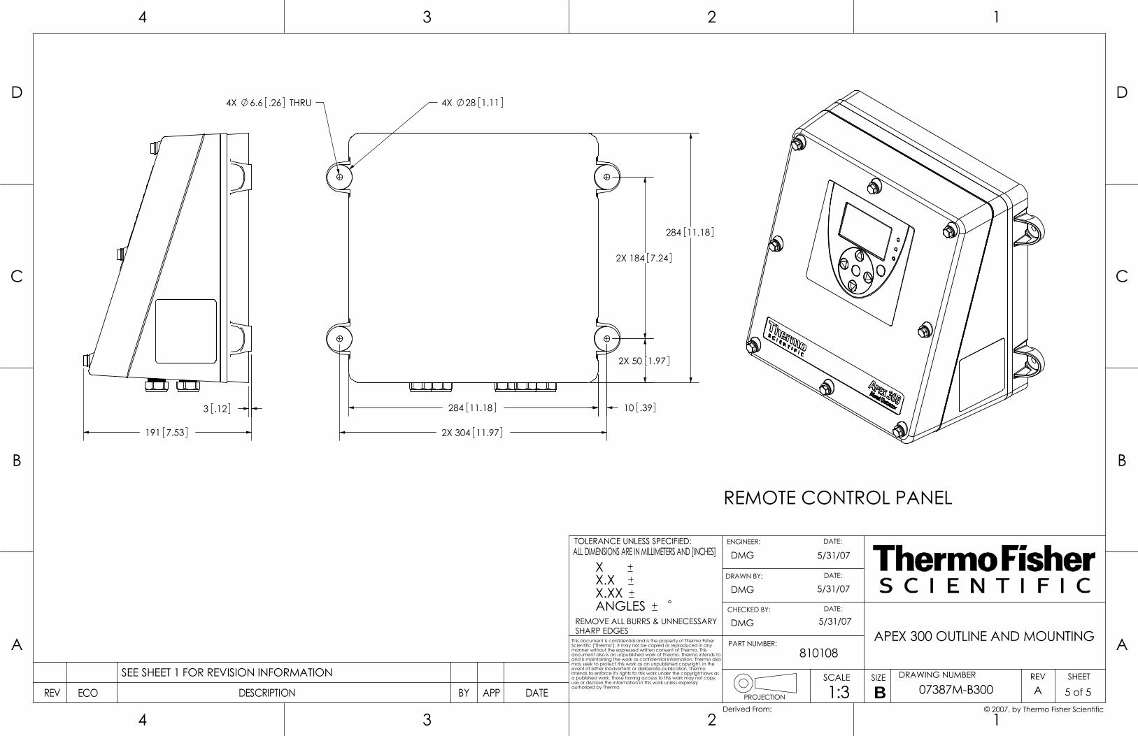
3 .12
191 7.53 2X 304 11.97
2X 184 7.24
284 11.18
284 11.18
2X 50 1.97
10 .39
4X 28 1.114X 6.6 THRU.26
REMOTE CONTROL PANEL
3
3
B
A
4
C
D
4
B
PROJECTION
2
REMOVE ALL BURRS & UNNECESSARYSHARP EDGES
PART NUMBER:
ENGINEER:
1
DRAWING NUMBERSIZESCALE
DATE:
SHEETREV
A
C
12
D
DATEAPPBYECO DESCRIPTIONREV
This document is confidential and is the property of Thermo Fisher Scientific ("Thermo"). It may not be copied or reproduced in any manner without the expressed written consent of Thermo. This document also is an unpublished work of Thermo. Thermo intends to and is maintaining the work as confidential information. Thermo also may seek to protect this work as an unpublished copyright. In the event of either inadvertent or deliberate publication, Thermo intends to enforce it's rights to this work under the copyright laws as a published work. Those having access to this work may not copy, use or disclose the information in this work unless expressly authorized by Thermo.
TOLERANCE UNLESS SPECIFIED:ALL DIMENSIONS ARE IN MILLIMETERS AND [INCHES]
CHECKED BY:
DATE:
DATE:
07387M-B300
APEX 300 OUTLINE AND MOUNTING
A 5 of 51:3
DMG 5/31/07
B SEE SHEET 1 FOR REVISION INFORMATION
DMG
DMG
5/31/07
5/31/07
810108
© 2007, by Thermo Fisher ScientificDerived From:
X X.X X.XX ANGLES
DRAWN BY:
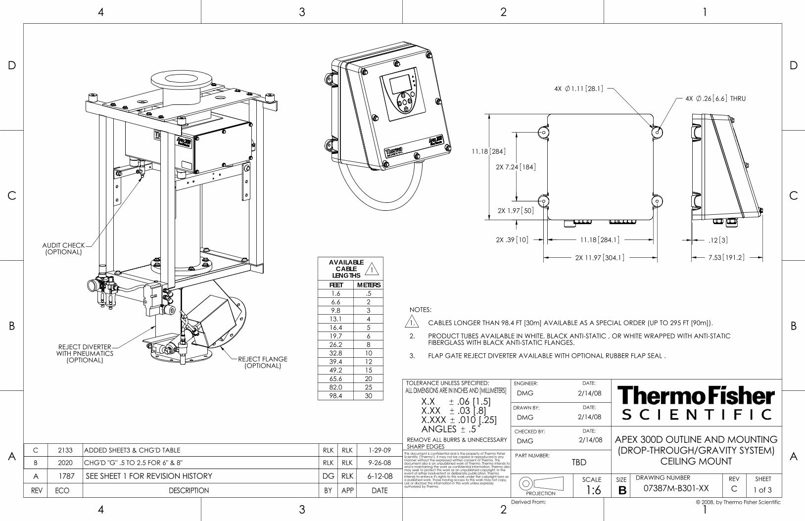
DATE:
3
3
B
A
4
C
D
4
B
PROJECTION
2
CHECKED BY:
SHARP EDGESPART NUMBER:
ENGINEER:
1
DRAWING NUMBERSIZESCALE
DATE:
SHEETREV
A
C
12
D
DATEAPPBYECO DESCRIPTIONREV
REMOVE ALL BURRS & UNNECESSARY
ALL DIMENSIONS ARE IN INCHES AND [MILLIMETERS]TOLERANCE UNLESS SPECIFIED:
authorized by Thermo.
This document is confidential and is the property of Thermo Fisher Scientific ("Thermo"). It may not be copied or reproduced in any manner without the expressed written consent of Thermo. This document also is an unpublished work of Thermo. Thermo intends to and is maintaining the work as confidential information. Thermo also may seek to protect this work as an unpublished copyright. In the event of either inadvertent or deliberate publication, Thermo intends to enforce it's rights to this work under the copyright laws as a published work. Those having access to this work may not copy, use or disclose the information in this work unless expressly
DATE:
07387M-B301-XX
(DROP-THROUGH/GRAVITY SYSTEM)APEX 300D OUTLINE AND MOUNTING
CEILING MOUNT
C 1 of 31:6
DMG 2/14/08
B 1787 RLK 6-12-08DGSEE SHEET 1 FOR REVISION HISTORYA
DMG
DMG
2/14/08
2/14/08
TBD
© 2008, by Thermo Fisher ScientificDerived From:
X.X .06 [1.5]X.XX .03 [.8]X.XXX .010 [.25]ANGLES .5
DRAWN BY:
RLKC 2133 ADDED SHEET3 & CHG'D TABLE
1
RLK 1-29-09
65.6 20
2.
3. FLAP GATE REJECT DIVERTER AVAILABLE WITH OPTIONAL RUBBER FLAP SEAL .
FIBERGLASS WITH BLACK ANTI-STATIC FLANGES.
PRODUCT TUBES AVAILABLE IN WHITE, BLACK ANTI-STATIC , OR WHITE WRAPPED WITH ANTI-STATIC
1. CABLES LONGER THAN 98.4 FT [30m] AVAILABLE AS A SPECIAL ORDER (UP TO 295 FT [90m]).
NOTES:
82.0 2598.4 30
AVAILABLE CABLE
LENGTHS FEET METERS1.6 .56.6 29.8 313.1 416.4 519.7 626.2 832.8 1039.4 1249.2 15
B 2020 CHG'D "G" .5 TO 2.5 FOR 6" & 8" RLK RLK 9-26-08
(OPTIONAL)REJECT FLANGE
(OPTIONAL)AUDIT CHECK
REJECT DIVERTERWITH PNEUMATICS
(OPTIONAL)
1.11
2X
28.14X
10.392X
304.111.97
284.111.18
2X
1847.242X
501.97
11.18 284
4X .26 THRU6.6
7.53 191.2
.12 3

MAX.30 [762]
MAX.Z
I.D.
M
M
F
OUTLET FLANGE DETAIL
S
F
B.C.
S .44 THRU,11.1"N" EQUALLY
SPACED ON B.C.
DETAIL A
PLASTIC INSULATINGSHOULDER WASHER
(SUPPLIED)
PLASTIC INSULATINGMOUNTING SPACER
(SUPPLIED)1.00 25.4
.41 10.3
CHECKED BY:
DATE:
3
3
B
A
4
C
D
4
B
PROJECTION
ALL DIMENSIONS ARE IN INCHES AND [MILLIMETERS]
REMOVE ALL BURRS & UNNECESSARYSHARP EDGES
PART NUMBER:
ENGINEER:
1
DRAWING NUMBERSIZESCALE
DATE:
SHEETREV
A
C
12
D
DATEAPPBYECO DESCRIPTION
2
TOLERANCE UNLESS SPECIFIED:
authorized by Thermo.REV
This document is confidential and is the property of Thermo Fisher Scientific ("Thermo"). It may not be copied or reproduced in any manner without the expressed written consent of Thermo. This document also is an unpublished work of Thermo. Thermo intends to and is maintaining the work as confidential information. Thermo also may seek to protect this work as an unpublished copyright. In the event of either inadvertent or deliberate publication, Thermo intends to enforce it's rights to this work under the copyright laws as a published work. Those having access to this work may not copy, use or disclose the information in this work unless expressly
DATE:
Derived From:
(DROP-THROUGH/GRAVITY SYSTEM)
07387M-B301-XX
APEX 300D OUTLINE AND MOUNTING
CEILING MOUNT
C 2 of 31:9
DMG 2/14/08
B SEE SHEET 1 FOR REVISION INFORMATION
DMG
DMG
2/14/08
2/14/08
TBD
© 2008, by Thermo Fisher Scientific
X.X .06 [1.5]X.XX .03 [.8]X.XXX .010 [.25]ANGLES .5
DRAWN BY:
ZERO VELOCITY
(SOME SYSTEMS, SEE TABLE)FIELD COMPRESSION FLANGES
(OPTIONAL)AUDIT CHECK
REJECT FLANGE(OPTIONAL)
A
C
R
T
HP
V
45°
G

3
3
B
A
4
C
D
4
B
PROJECTION
2
REMOVE ALL BURRS & UNNECESSARYSHARP EDGES
PART NUMBER:
ENGINEER:
1
DRAWING NUMBERSIZESCALE
DATE:
SHEETREV
A
C
12
D
DATEAPPBYECO DESCRIPTIONREV
This document is confidential and is the property of Thermo Fisher Scientific ("Thermo"). It may not be copied or reproduced in any manner without the expressed written consent of Thermo. This document also is an unpublished work of Thermo. Thermo intends to and is maintaining the work as confidential information. Thermo also may seek to protect this work as an unpublished copyright. In the event of either inadvertent or deliberate publication, Thermo intends to enforce it's rights to this work under the copyright laws as a published work. Those having access to this work may not copy, use or disclose the information in this work unless expressly authorized by Thermo.
TOLERANCE UNLESS SPECIFIED:ALL DIMENSIONS ARE IN INCHES AND [MILLIMETERS]
CHECKED BY:
DATE:
DATE:
07387M-B301-XX
APEX 300D OUTLINE AND MOUNTING(DROP-THROUGH/GRAVITY SYSTEM)
CEILING MOUNT
C 3 of 31:9
DMG 2/14/08
B SEE SHEET 1 FOR REVISION INFORMATION
DMG
DMG
2/14/08
2/14/08
TBD
© 2008, by Thermo Fisher ScientificDerived From:
X.X .06 [1.5]X.XX .03 [.8]X.XXX .010 [.25]ANGLES .5
DRAWN BY:
TAB CHARTI.D.
PRODUCT TUBE METAL DETECTORAPERTURE (mm)
FIELD COMPRESSION FLANGES
B.C.(BOLT CIRCLE )
F(FLANGE ) G
H(OVERALL HEIGHT)
M N(# FLANGE
HOLES)
P R(REJECTER HEIGHT) S T
(TUBE HEIGHT) V Z
inch mm C=145mm C=250mm inch mm inch mm inch mm inch mm inch mm inch mm inch mm inch mm inch mm inch mm inch mm
3.00 76.2 100 x 100 NO NO 5.00 127.0 6.0 152 .5 13 36.20 919.5 16.5 419 4 20 508 9.20 233.7 3.26 82.8 27 685.8 7 178 23 584
4.00 101.6 125 x 125 NO NO 6.50 165.1 7.5 191 1.5 38 39.21 995.9 17.5 445 4 20 508 11.21 284.7 4.26 108.2 28 711.2 8 203 22 559
4.75 120.6 150 x 150 YES NO 7.75 196.9 9.0 229 2.5 64 42.24 1072.9 18.5 470 8 20 508 13.24 336.3 5.30 134.6 29 736.6 9 229 21 533
5.75 146.0 175 x 175, C = 145 YES ---9.25 235.0 10.5 267 2.5 13 50.27 1276.9 19.5 495 8
26 66015.27 387.9 6.36 161.5 35 889
9 229 21 533
5.75 146.0 175 x 175, C = 250 --- YES 24 610 11 279 19 483
7.87 200.0 225 x 225, C = 145 YES ---12.00 304.8 13.5 343 2.5 13 54.31 1379.5 21.5 546 8
26 66019.31 490.5 8.36 212.3 35 889
9 229 21 533
7.87 200.0 225 x 225, C = 250 --- YES 24 610 11 279 19 483

ADAPTER(OPTIONAL)
ADAPTER(OPTIONAL)
DATE:
3
3
B
A
4
C
D
4
B
PROJECTION
2
CHECKED BY:
SHARP EDGESPART NUMBER:
ENGINEER:
1
DRAWING NUMBERSIZESCALE
DATE:
SHEETREV
A
C
12
D
DATEAPPBYECO DESCRIPTIONREV
REMOVE ALL BURRS & UNNECESSARY
ALL DIMENSIONS ARE IN INCHES AND [MILLIMETERS]TOLERANCE UNLESS SPECIFIED:
authorized by Thermo.
This document is confidential and is the property of Thermo Fisher Scientific ("Thermo"). It may not be copied or reproduced in any manner without the expressed written consent of Thermo. This document also is an unpublished work of Thermo. Thermo intends to and is maintaining the work as confidential information. Thermo also may seek to protect this work as an unpublished copyright. In the event of either inadvertent or deliberate publication, Thermo intends to enforce it's rights to this work under the copyright laws as a published work. Those having access to this work may not copy, use or disclose the information in this work unless expressly
DATE:
07387M-B302-XX
(PIPELINE SYSTEM)APEX 300P OUTLINE AND MOUNTING
CEILING MOUNT
A 1 of 21:8
DMG 4/23/08
B1787 RLK 5-14-08RLKRELEASEDA
DMG
DMG
4/23/08
4/23/08
TBD
© 2008, by Thermo Fisher ScientificDerived From:
X.X .06 [1.5]X.XX .03 [.8]X.XXX .010 [.25]ANGLES .5
DRAWN BY:
CABLES LONGER THAN 98.4 FT [30m] AVAILABLE AS A SPECIAL ORDER (UP TO 295 FT [90m]).
2. PIPES AVAILABLE IN NYLON OR FIBERGLASS WRAPPED PTFE.
1.
NOTES:
PRODUCT TUBET
(TUBE LENGTH)
METAL DETECTORAPERTURE
SIZE
S(SPOOL PIECEWITH GASKET)
CENTERSUPPORT/
CLAMP
V(VALVE WITH
GASKET)
L(OVERALL SYSTEM
TUBE LENGTH)A B C HNOMINAL
SIZE TYPEinch inch mm mm inch mm inch mm inch mm inch mm inch mm inch mm inch mm
2
PIPE 24 610 75- - NO
6.87 174.5
30.87 784.1 32.00 812.87.00 177.8
15.47 392.98.40 213.412.06 306.3
YES42.93 1090.4 44.00 1117.6 27.53 699.3
24.06 611.1 54.93 1395.2 56.00 1422.4 39.53 1004.1
HOSE 36 914 100- - NO 42.87 1088.9 38.00 965.2
8.00 203.2
21.47 426.2
8.89 225.9
12.06 306.3YES
54.93 1395.2 50.00 1270.0 33.53 732.524.06 611.1 66.93 1700.0 62.00 1574.8 45.53 1037.3
2.5 or 3 PIPE 24 610 100- - NO
9.50 241.3
33.50 850.9 33.00 838.2 16.78 472.212.06 306.3
YES45.56 1157.2 45.00 1143.0 28.84 778.5
24.06 611.1 57.56 1462.0 57.00 1447.8 40.84 1083.3
2.5 HOSE 36 914 100- - NO 45.50 1155.7 39.00 990.6 22.78 545.3
12.06 306.3YES
57.56 1462.0 51.00 1295.4 34.84 851.724.06 611.1 69.56 1766.8 63.00 1600.2 46.84 1156.5
3 HOSE 36 914 125- - NO 45.50 1155.7 39.00 990.6
9.00 228.6
22.78 578.6
9.39 238.4
12.06 306.3YES
57.56 1462.0 51.00 1295.4 34.84 884.924.06 611.1 69.56 1766.8 63.00 1600.2 46.84 1189.7
4
PIPE 24 610 125- - NO
13.12 333.2
37.12 942.8 35.00 889.0 18.59 578.612.06 306.3
YES49.18 1249.2 47.00 1193.8 30.65 884.9
24.06 611.1 61.18 1554.0 59.00 1498.6 42.65 1189.7
HOSE 36 914 150- - NO 49.12 1247.6 41.00 1041.4
10.00 254.024.59 624.6
9.88 250.912.06 306.3YES
61.18 1554.0 53.00 1346.2 36.65 930.924.06 611.1 73.18 1858.8 65.00 1651.0 48.65 1235.7
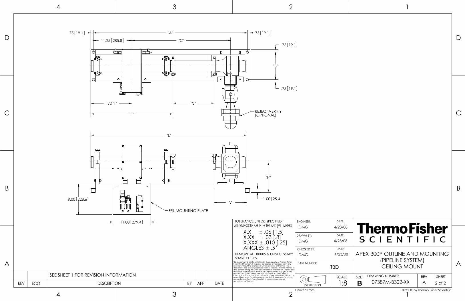
"H"
"V"
"L"
1/2 "T"
"C"11.25 285.8
FRL MOUNTING PLATE
1.00 25.49.00 228.6
11.00 279.4
REJECT VERIFIY(OPTIONAL)
"A"
"B"
"S"
"T"
.75 19.1
.75 19.1 .75 19.1
.75 19.1
3
3
B
A
4
C
D
4
B
PROJECTION
2
REMOVE ALL BURRS & UNNECESSARYSHARP EDGES
PART NUMBER:
ENGINEER:
1
DRAWING NUMBERSIZESCALE
DATE:
SHEETREV
A
C
12
D
DATEAPPBYECO DESCRIPTIONREV
This document is confidential and is the property of Thermo Fisher Scientific ("Thermo"). It may not be copied or reproduced in any manner without the expressed written consent of Thermo. This document also is an unpublished work of Thermo. Thermo intends to and is maintaining the work as confidential information. Thermo also may seek to protect this work as an unpublished copyright. In the event of either inadvertent or deliberate publication, Thermo intends to enforce it's rights to this work under the copyright laws as a published work. Those having access to this work may not copy, use or disclose the information in this work unless expressly authorized by Thermo.
TOLERANCE UNLESS SPECIFIED:ALL DIMENSIONS ARE IN INCHES AND [MILLIMETERS]
CHECKED BY:
DATE:
DATE:
07387M-B302-XX
APEX 300P OUTLINE AND MOUNTING(PIPELINE SYSTEM)CEILING MOUNT
A 2 of 21:8
DMG 4/23/08
B SEE SHEET 1 FOR REVISION INFORMATION
DMG
DMG
4/23/08
4/23/08
TBD
© 2008, by Thermo Fisher ScientificDerived From:
X.X .06 [1.5]X.XX .03 [.8]X.XXX .010 [.25]ANGLES .5
DRAWN BY: