Thermo Probe, Inc. - Hartwig Instruments€¦ · ThermoProbe, Inc. Instructions for use- Models...
5
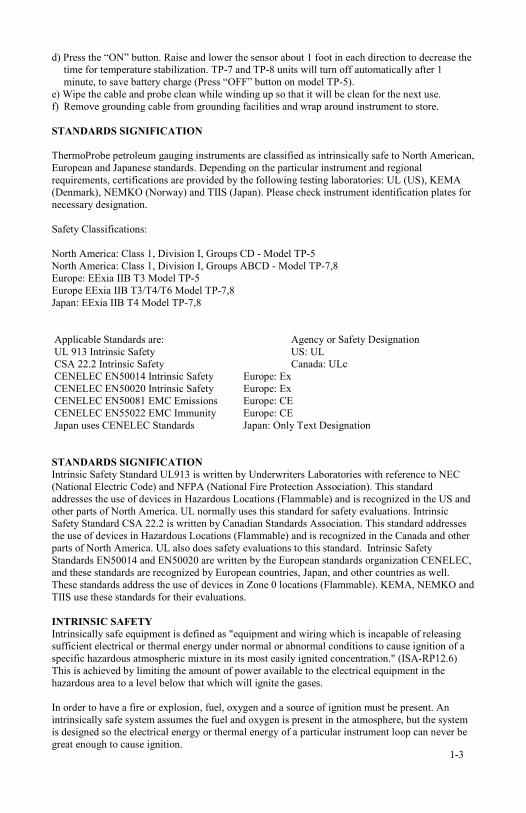
Thermo Probe, Inc. Instruction Manual English Switch Display Carry Strap Ground Clip Probe TP-5 Display Carry Strap Ground Clip Probe Switch TP-7 Switch Display Carry Strap Ground Clip Probe TP-8 1-1
Transcript of Thermo Probe, Inc. - Hartwig Instruments€¦ · ThermoProbe, Inc. Instructions for use- Models...

Thermo Probe, Inc. Instruction Manual
English Switch
Display
Carry Strap
Ground Clip
Probe
TP-5
Display
Carry Strap
Ground Clip
Probe
Switch
TP-7
Switch Display
Carry Strap Ground Clip
Probe
TP-8
1-1

ThermoProbe, Inc. Instructions for use- Models TP-5, TP-7, and TP-8 The manual describes basic function and use of ThermoProbe instruments and basic safety instructions. The ThermoProbe Portable Electronic Thermometer is a portable digital temperature instrument. Intended use of ThermoProbe is both in hazardous (flammable) and non-hazardous areas. Typical areas for use: a) Tankfarms or tanks containing oil or chemical products. b) Refineries, chemical plants, hot-water producing plants, etc. c) Marine transportations such as; tankers, barges or other transport facilities. d) Food processing plants. e) Other industrial plants where temperature measuring is needed. FUNCTION ThermoProbe case enclosures are built upon knowledge from previous models and constructed to withstand the rigors of field use. Measuring cable is made with a Teflon FEP or PFA outer layer with carbon blended to reduce static charge. DuPont Kevlar reinforcement is included in cables for select models in order to resist cuts. Cable and sensor probe storage is integral with the case. Electronic circuits are placed inside the case, well protected. To reach the electronic circuits and battery, the faceplate, side-plates, or battery cover must be removed depending on model. Measured temperature is displayed via Liquid Crystal Display (LCD) visible through a window on the case. Electronic is CMOS technology, and powered by one non-rechargeable 9 volt battery. Cable is connected at one end to electronic circuits and to the probe containing a “solid-state” type chip or Platinum Resistive Temperature Device (RTD) on TP-7 and TP-8. Depress the sealed “ON” button on the case to read measured temperature on the display. For use in hazardous areas a grounding cable is included with the instrument. Also a carrying strap is enclosed for easy carrying. USE OF INSTRUMENT As ThermoProbes are intended to be used in hazardous locations, user must have a working knowledge of appropriate safety instructions. SEE MARKINGS ON INSTRUMENT AND READ FOLLOWING INSTRUCTIONS PROCEDURES BEFORE USE a) The inspector must have a thorough knowledge of the products to be measured and must know of the safety measures to be taken when working with the material to be measured. b) Instrument shall be checked concerning severe defects; check that instrument is complete (including grounding cable), has good batteries, etc. If necessary, check measurement accuracy. If any defects are found, the instrument should not be used until repairs have been made. c) Instrument, especially cable and probe, should be clean both for safety reasons and ease of use. d) Estimation should be carried out to validate if physical place for measuring is considered a primary or secondary, or both, risk source. MEASURING PROCEDURES a) Check wind direction or other air-movements at place for measuring to avoid inhaling vapors. b) Attach grounding cable/bonding cable to bare metal grounding facilities associated with the vessel. c) Lower cable and probe into intended product at desired depth. 1-2
d) Press the “ON” button. Raise and lower the sensor about 1 foot in each direction to decrease the time for temperature stabilization. TP-7 and TP-8 units will turn off automatically after 1 minute, to save battery charge (Press “OFF” button on model TP-5). e) Wipe the cable and probe clean while winding up so that it will be clean for the next use. f) Remove grounding cable from grounding facilities and wrap around instrument to store. STANDARDS SIGNIFICATION ThermoProbe petroleum gauging instruments are classified as intrinsically safe to North American, European and Japanese standards. Depending on the particular instrument and regional requirements, certifications are provided by the following testing laboratories: UL (US), KEMA (Denmark), NEMKO (Norway) and TIIS (Japan). Please check instrument identification plates for necessary designation. Safety Classifications: North America: Class 1, Division I, Groups CD - Model TP-5 North America: Class 1, Division I, Groups ABCD - Model TP-7,8 Europe: EExia IIB T3 Model TP-5 Europe EExia IIB T3/T4/T6 Model TP-7,8 Japan: EExia IIB T4 Model TP-7,8 Applicable Standards are: Agency or Safety Designation UL 913 Intrinsic Safety US: UL CSA 22.2 Intrinsic Safety Canada: ULc CENELEC EN50014 Intrinsic Safety Europe: Ex CENELEC EN50020 Intrinsic Safety Europe: Ex CENELEC EN50081 EMC Emissions Europe: CE CENELEC EN55022 EMC Immunity Europe: CE Japan uses CENELEC Standards Japan: Only Text Designation STANDARDS SIGNIFICATION Intrinsic Safety Standard UL913 is written by Underwriters Laboratories with reference to NEC (National Electric Code) and NFPA (National Fire Protection Association). This standard addresses the use of devices in Hazardous Locations (Flammable) and is recognized in the US and other parts of North America. UL normally uses this standard for safety evaluations. Intrinsic Safety Standard CSA 22.2 is written by Canadian Standards Association. This standard addresses the use of devices in Hazardous Locations (Flammable) and is recognized in the Canada and other parts of North America. UL also does safety evaluations to this standard. Intrinsic Safety Standards EN50014 and EN50020 are written by the European standards organization CENELEC, and these standards are recognized by European countries, Japan, and other countries as well. These standards address the use of devices in Zone 0 locations (Flammable). KEMA, NEMKO and TIIS use these standards for their evaluations. INTRINSIC SAFETY Intrinsically safe equipment is defined as "equipment and wiring which is incapable of releasing sufficient electrical or thermal energy under normal or abnormal conditions to cause ignition of a specific hazardous atmospheric mixture in its most easily ignited concentration." (ISA-RP12.6) This is achieved by limiting the amount of power available to the electrical equipment in the hazardous area to a level below that which will ignite the gases. In order to have a fire or explosion, fuel, oxygen and a source of ignition must be present. An intrinsically safe system assumes the fuel and oxygen is present in the atmosphere, but the system is designed so the electrical energy or thermal energy of a particular instrument loop can never be great enough to cause ignition. 1-3

ADDITIONAL SAFETY INSTRUCTIONS a) Battery must be changed in Non-hazardous area. Battery must be of correct type, see instrument identification plates on instrument. b) Exchange of components other than original components may compromise the safety and is not recommended. BATTERY CHECK ThermoProbe models TP-7 and TP-8 will indicate a flashing readout of “Lo” in the display. Replace battery if this occurs in order to prevent inaccurate readings. TP-5 model – battery is considered good as long as a measured value appears on the display when pressing the “ON” button. However, if backlight will not light when in darkness or if measured value is unstable, battery replacement is recommended. REPLACING BATTERY a) Move into non-hazardous area. b) Remove the four screws holding the battery cover on the TP-5 and TP-8 models, or the three faceplate screws on the TP-7 model. c) Slide the battery cover out on the TP-5 and TP-8. Remove the circuit board/faceplate assembly on the TP-7. d) Lift battery at the outer end and pull the battery away from the plus/minus connections. e) Mount the new battery by pressing appropriate (+)/(-) connections together and push the battery to its correct position. f) (TP-5 and TP-8) Mount the battery cover and fasten the four screws. (TP-7) Reinstall the circuit assembly and fasten the three screws. CALIBRATION PROCEDURE Refer to API 7.3 for Calibration Verification Procedures: Calibration is not to be performed in any environment considered to be hazardous. ThermoProbes should be calibrated at least annually to keep up to the standard of high accuracy. Please check for drift of electronic circuit, against proper temperature stable bath. Calibration requires two precision temperature reference points, for example; 0.0°C (32.0°F) and 90.0 °C (194°F) in stable liquid calibration baths or similar certified temperature calibration equipment. Equipment needed:
• Ice Bath with certified reference thermometer. • Warm to hot fluid bath between at 20°C (approx 68°F) or higher up to 90°C (approx
194°F) with certified reference thermometer. (see Note)* • Small Phillips head or standard blade screwdriver to gain access to circuit board or
calibration adjusters. • Micro-style bladed screwdriver for electronics adjustment or similar tiny flat blade
screwdriver for turning the adjusters.
*Note for field calibration: If entire range capability of instrument is not required, the high adjustment can be made at a temperature relatively close to the common temperature of the liquid measured and accuracy will be maintained within the limited range. For example: If liquid to be measured is commonly less than 38°C (approx. 100°F), then a “span” or “high point” calibration can be made with a stable bath at room temperature of 21°C (70°F) to 27°C (80°F) using a certified thermometer for reference. Measurement accuracy will be maintained as long as liquid temperature to be measured does not exceed approx. 40°C (105°F).
1-4

To calibrate proceed with the following steps: The following instructions specify the TP-5, TP-7 and TP-8, other models are similar. **Refer to Appendix A for special instruction variation for ThermoProbe model TP-2. a) For model TP-5, remove the two screws covering “zero” and “span” adjustment screws on the outside of front side of the case. The “zero” is the lower most adjuster and the “span” is located directly above. In order to access the adjustment screws on the TP-7 remove the circuit board assembly from case as described in “Replacing Battery” section above. TP-8 adjusting screw access requires removal of bottom cover plate by removing four screws. The adjusters on the TP-7 and TP-8 are found side by side on the lower edge of the circuit board. Refer to markings on the circuit board to verify which is “zero” and which is “span”. b) Lower the probe into the 0.0 °C temperature bath and read temperature on the ThermoProbe display. If deviation occurs, adjust the “zero” adjustment screw to get the same temperature as certifiable bath temperature. c) Lower the probe into the 90.0 °C temperature stable bath and read temperature on the display. If deviation occurs, adjust the “span” adjustment screw to the same temperature as the certifiable bath temperature. d) Repeat step b) and step c) until same accordance between the ThermoProbe and both bath temperatures. Span is now set to 90.0 °C. e) Replace the covering screw on “zero” and “span” places on the TP-5 or reassemble the TP-7 or TP-8. APPENDIX A. The following refers to the special calibration procedure for the “high zero” adjustment on the TP-2 model. This model is currently out of production. Many of these instruments remain in the field and these instructions are provided as a courtesy in order to assist in proper calibration procedures. The TP-2 differs from all other ThermoProbe models due to its having three adjusters rather than two. The third adjuster (called the “high Zero”) is used to correct calibration on Fahrenheit models only and only for temperatures over 200°F. Remove bottom cover to access the three adjusters. Follow the calibration procedures listed in the body of this document for temps under 200°F. After the “zero” and “span” have been set, then place the probe sensor in a heated circulating bath at between 195.0°F and 199.0°F. Allow the reading to stabilize. Flip the range switch on the right side front of the TP-2 so that it is in the up position “over 200°F” marking. Adjust the “high zero” adjuster until the display reads according to the following chart and then reassemble the instrument: High Range Table for TP-2 Bath High Zero Temp. °F Reading 195.0 -5.4 195.5 -5.0 196.0 -4.4 196.5 -3.9 197.0 -3.4 197.5 -2.9 198.0 -2.4 198.5 -1.9 199.0 -1.4 1-5