Thermo-Mechanical laser cladding simulations of M4 High ...
24
Thermo-Mechanical laser cladding simulations of M4 High Speed Steel R.T. Jardin, J.T. Tchuindjang, L. Duchêne, R. Carrus, R. Pesci, A. Mertens, A.M. Habraken, H.S. Tran 1
Transcript of Thermo-Mechanical laser cladding simulations of M4 High ...

Thermo-Mechanical laser cladding simulations of M4 High Speed Steel
R.T. Jardin, J.T. Tchuindjang, L. Duchêne,
R. Carrus, R. Pesci, A. Mertens,
A.M. Habraken, H.S. Tran
1

2
Material High Speed Steel M4
• Fe-Cr-C-X alloys with X: carbide-forming element(i.e. V, Nb, Mo or W)• Hard carbides ⇒ High hardness and wear resistance• Applications: high speed machining, cutting tools, cylinders for hot rolling mills, molds...
4th workshop of Metal Additive Manufacturing

For High Speed Steel (M4 grade) wt%
Particle size [50 to 150 μm]
Direct Energy Deposition DEDprocess
C Cr Mo V W Ni Si Fe
1.35 4.30 4.64 4.10 5.60 0.34 0.9 0.33
3
Towards a thermo- mechanical validated model
4th workshop of Metal Additive Manufacturing
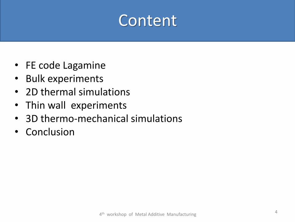
• FE code Lagamine• Bulk experiments• 2D thermal simulations • Thin wall experiments• 3D thermo-mechanical simulations• Conclusion
4
Content
4th workshop of Metal Additive Manufacturing

5
Active
elementNewly active
element
Inactive element
Convection and
radiation element
convection-radiation elem. on vertical planes of the clad not drawn
Element birth technique
For a thin wall 3D Bulk Sample 2D

6
Metallic structureTemperature
Stress and strain
Phase transformation
Latent heat
Thermalstress
Variation ofmechanical
parametersHeat generation
due to deformation
Transformationstrain andplasticity
Charact.mixture law
Mechanical inducedtransformation
Kinetic modification
Coupled thermo mechanical metallurgical analysis during the cooling process of steel pieces(A.M.Habraken, M. Bourdouxhe, Eur.J. Mec A/Solids 11 (1992)
Lagamine FE codeCoupled thermo metallurgic mechanical
Mechanical equations
4
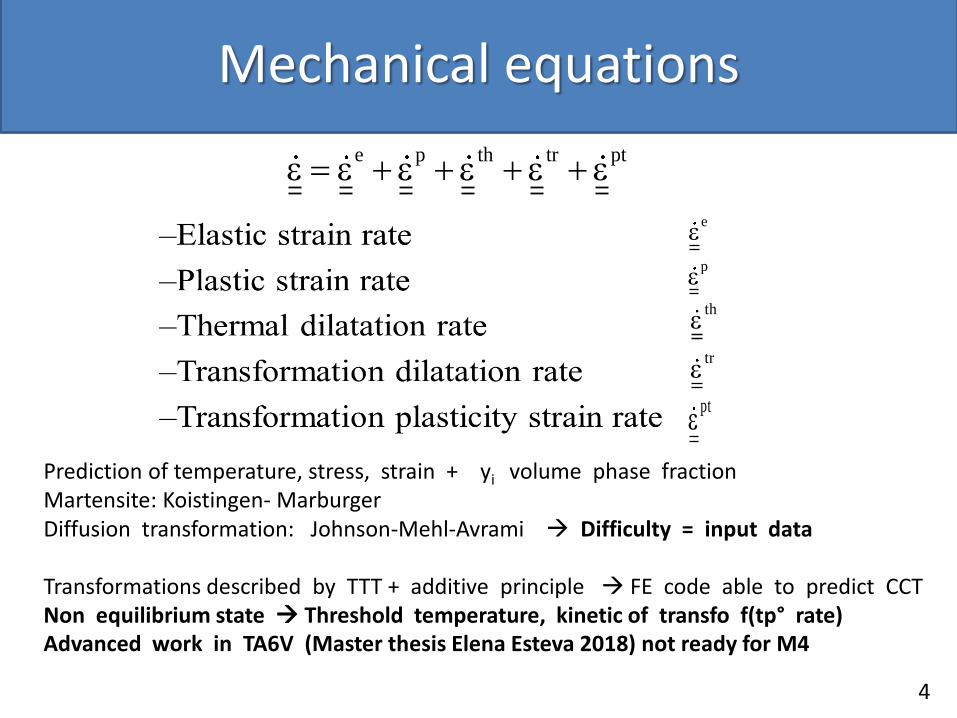
Prediction of temperature, stress, strain + yi volume phase fractionMartensite: Koistingen- MarburgerDiffusion transformation: Johnson-Mehl-Avrami Difficulty = input data
Transformations described by TTT + additive principle FE code able to predict CCT Non equilibrium state Threshold temperature, kinetic of transfo f(tp° rate)Advanced work in TA6V (Master thesis Elena Esteva 2018) not ready for M4
e p th tr pt
e
p
th
tr
pt

Heat transfer per conduction
Heat transfer per convection and radiation
Melting latent Heat
Enthalpic formulation
int p
T T T Tk k k Q c
x x y y z z t
4 4
0 0.( . ) ( ) ( )K T n h T T T T
Heat Capacity DensityVolume energy
Convection Coef. Stefan-Boltzmann Constant Emissivity
Enthalpy
Thermal equations
Conductivity
4
4th workshop of Metal Additive Manufacturing 9
e eE T, y T, y
Tr( )I1 T, y 1 2 T, y
23f : R
2
p f
p pp p p
y eq eq
2R T, y E T, y avec :
3
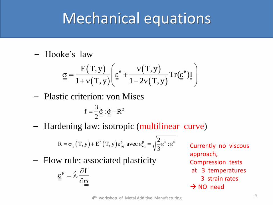
– Plastic criterion: von Mises
– Hardening law: isotropic (multilinear curve)
– Flow rule: associated plasticity
– Hooke’s law
Mechanical equations
Currently no viscousapproach,Compression tests at 3 temperatures
3 strain rates NO need
Lagamine
Stresses(σx , σy ,σz , σxy)
Strains(εth, εp, εph, εptr)
Phase rates(%Fe, %Pe, %Ma)
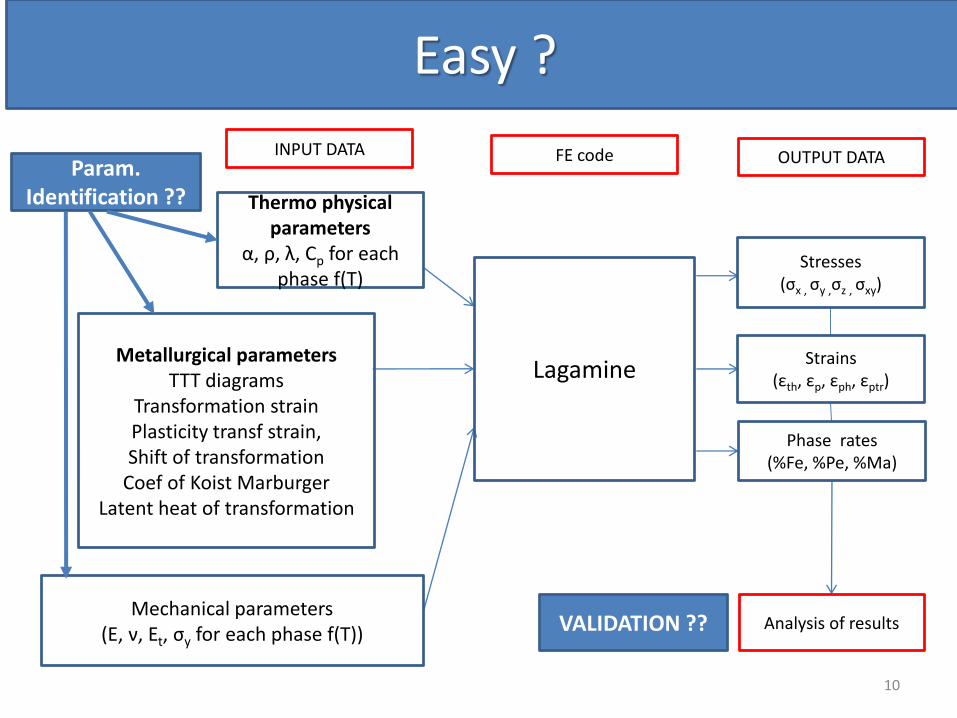
Thermo physical parameters
α, ρ, λ, Cp for eachphase f(T)
Metallurgical parametersTTT diagrams
Transformation strainPlasticity transf strain,Shift of transformation
Coef of Koist MarburgerLatent heat of transformation
Mechanical parameters(E, ν, Et, σy for each phase f(T))
Analysis of results
INPUT DATA FE code OUTPUT DATA
10
Easy ?
VALIDATION ??
Param. Identification ??
11
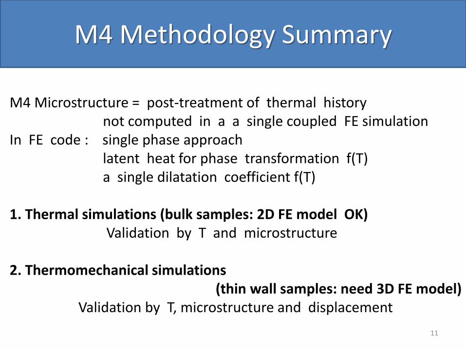
M4 Methodology Summary
M4 Microstructure = post-treatment of thermal history not computed in a a single coupled FE simulation
In FE code : single phase approach latent heat for phase transformation f(T) a single dilatation coefficient f(T)
1. Thermal simulations (bulk samples: 2D FE model OK)Validation by T and microstructure
2. Thermomechanical simulations (thin wall samples: need 3D FE model)
Validation by T, microstructure and displacement

12
Validated 2D thermal simulations
In put
conduction, heat capacity, latent heat measured on samples extracted from the clad & the substrate (DSC, Laser flash, dilatometry)
Convection, Radiation, laser absorption fitted by inverse modelling
Target BOTH Temperature + Melt pool depth measured
4th workshop of Metal Additive Manufacturing

13
“2D” bulk samples
40 x 40 x 27.5 mm (972 tracks)
4 ThermocouplesThermal measurement in the substrate
4th workshop of Metal Additive Manufacturing

14
“2D” bulk samples
Tp° in the substratePredicted Tp° in the clad
Melt pool depthKey data for identifying singel set of data by inverse simulations (convection, radiation absorption coefficient)
4th workshop of Metal Additive Manufacturing
15
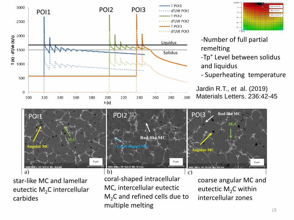
a) b) c)
Fig. 3: SEM-BSE micrographs of a) POI1 with star-like MC and lamellar eutectic M2C intercellular carbides; b) POI2
with coral-shaped intracellular MC, intercellular eutectic M2C and refined cells due to multiple melting; c) POI3 with
coarse angular MC and eutectic M2C within intercellular zones.
Angular MC
Rod-like MC
M2C
Angular MC
Rod-like MC
Coral-shaped MC
M2C
8 µm 8 µm 8 µm
POI1 POI3POI2
star-like MC and lamellar eutectic M2C intercellular carbides
coral-shaped intracellular MC, intercellular eutectic M2C and refined cells due to multiple melting
coarse angular MC and eutectic M2C within intercellular zones
Jardin R.T., et al. (2019)
Materials Letters. 236:42-45
-Number of full partial remelting-Tp° Level between solidus and liquidus- Superheating temperature
Solidus
POI1 POI2 POI3
16
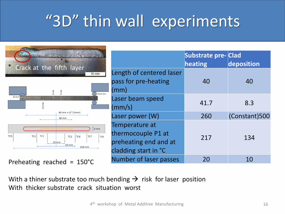
“3D” thin wall experiments
Preheating reached = 150°C
With a thiner substrate too much bending risk for laser positionWith thicker substrate crack situation worst
Substrate pre-heating
Clad deposition
Length of centered laser pass for pre-heating (mm)
40 40
Laser beam speed (mm/s)
41.7 8.3
Laser power (W) 260 (Constant)500Temperature at thermocouple P1 at preheating end and at cladding start in °C
217 134
Number of laser passes 20 10
4th workshop of Metal Additive Manufacturing
Crack at the fifth layer

17
“3D” thermal analysis - thin walls
Previous measured thermophysicalparameters for the clad
Substrate 42crMo4different origin than for bulk sample
Impossible to recover temperaturemeasurements with previous values of conductivity and thermal capacity.
New measurements indeed showeddifferent results for conductivity and heat capacity
(Previous block for bulk sample in martensite state, current bars in Pearlitic state)
Simulations until 5th layerConvection needs to be function of TConstant value not OK

18
“3D” thermo-mechanical data analysis - thin walls
Results for bilinear stress-strain curves
Far Lesssensitive for multi linerarcurves
Sensitivity on the 5 first layers
Numerical annealing temperature: plastic strain if forgotten if tp° decreases belowthis annealing tp°
4th workshop of Metal Additive Manufacturing
19
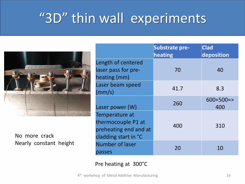
“3D” thin wall experiments
Substrate pre-heating
Clad deposition
Length of centered laser pass for pre-heating (mm)
70 40
Laser beam speed (mm/s)
41.7 8.3
Laser power (W)260
600+500=>400
Temperature at thermocouple P1 at preheating end and at cladding start in °C
400 310
Number of laser passes
20 10
Pre heating at 300°C
4th workshop of Metal Additive Manufacturing
No more crackNearly constant height

20
“3D” thin wall experiments
4th workshop of Metal Additive Manufacturing
3 Experiments with similar conditions
Temperature history Vertical displacement at the middle
Z
.. .x
y
21
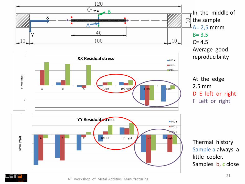
A
BCIn the middle of the sampleA= 2,5 mmmB= 3.5C= 4.5Average good reproducibility
At the edge2.5 mm D E left or right F Left or right
..
Thermal history Sample a always a little cooler.Samples b, c close

22
“3D” thermo-mechanical data analysis - thin walls - validation?
-0,7
-0,6
-0,5
-0,4
-0,3
-0,2
-0,1
0
0,1
0 20 40 60 80 100 120 140 160
zz (
mm
)
t (s)
Numerical annealing temperature 600Kor 800 K(superposed)
No effect of annealing temperatureDetailed dilatation coef of the clad: Bainite // Mart-Aust similar value
closer to experiment than “steel data’” but still far from validation
To be checked dilatation of substrate…
EXP
Steel
BainiteMart–
Austenite
Steel
Bainite
Mart–Austenite K
Dilatation coefficient

Residual stress
23
-1000
-800
-600
-400
-200
0
200
400
600
800
A B C D/E F
Stre
ss (
Mp
a)
XX Residual Stress
P42b
alpha Neda 600K
alpha Neira 600K
alpha Dedry 600K
-200
-150
-100
-50
0
50
100
150
A B C D/E F
Stre
ss (
Mp
a)
YY Residual stress
P42b
alpha Neda 600K
alpha Neira 600K
alpha Dedry 600K
EXPSteelMart-AusteniteBainite
“3D” thermo-mechanical data analysis - thin walls - validation?
4th workshop of Metal Additive Manufacturing
A B C DEF
No consistency with experiment b More consistency with experiment b
Iso value and gradients should be studied
Effect of substrate dilatation coefficientshould be checked
Predictions for numerical annealing of 600K
Sensitivity to dilatation coefficient

24
Conclusions - Perspectives
FE thermo-mechanical model available, without activation of the phenomenological phase transformation model Trials to model solid latent heat and dilatation effect at correct time
Annealing temperature effect depends on the shape of hardening curvesNo effect on prediction of residual stress or displacement for the correct stress-strain curves
Validation by temperature, melt pool size, displacement, residual stress, microstructurenot yet reached…
X Ray measurements provide quite scattered data Complex microstructure justifies scattering + Laser cladding experiment repeatability
Additional way :Different experimental conditions crack and no cracks cases + hot rupture value: another FE validation method