Thermo-mechanical fatigue behaviour and life prediction of ...
14
MultiCraft International Journal of Engineering, Science and Technology Vol. 3, No. 6, 2011, pp. 88-101 INTERNATIONAL JOURNAL OF ENGINEERING, SCIENCE AND TECHNOLOGY www.ijest-ng.com © 2011 MultiCraft Limited. All rights reserved Thermo-mechanical fatigue behaviour and life prediction of C-1023 nickel based superalloy A. García de la Yedra, A. Martín-Meizoso, R. Rodríguez Martín, J.L. Pedrejón CEIT and TECNUN (University of Navarra) Paseo de Manuel Lardizábal, 15, 20018 San Sebastián, SPAIN E-mail: [email protected] Abstract Nickel based superalloys are used for manufacturing turbine blades and vanes components due to their ability to withstand high stress levels at high temperatures. The complex thermo-mechanical fatigue loadings that those components suffer (as a result of start ups and shutdowns) make life assessment a complex task. Working towards this end, the thermo-mechanical fatigue behaviour and life prediction of C-1023 nickel based superalloy was studied in this work. Several tests were conducted at different phase-shifts between mechanical and thermal cycles. It was found out that in-phase tests (where peak temperature coincides with maximum mechanical strain) were prone to intergranular fracture due to creep contribution. On the other hand, out of phase tests showed clear transgranular paths ascribed to fatigue damage. Finally, some simple damage parameters were found to be suitable tools for life prediction. Keywords: C-1023 superalloy, damage mechanisms, life prediction, thermo-mechanical fatigue. DOI: http://dx.doi.org/10.4314/ijest.v3i6.8 1. Introduction The term superalloy is used to describe a group of alloys developed for use in aircraft turbine components such as blades, vanes and discs. The combination of mechanical and thermal cyclic loads during operation, as a result of start ups, shutdowns and transients, leads these components to failure due to a process termed thermo-mechanical fatigue (TMF). Their life assessment is of prime importance so that a reliable product is designed that reduces maintenance costs. Traditional methods to determine life of blades was based on high temperature low cycle fatigue (LCF) testing techniques. This was done by conducting tests at a constant temperature and equal to the maximum operating value during service. The introduction of Thermo-mechanical Fatigue (TMF) tests as a diagnostic device (Hopkins, 1976), allowed determining differences between both load histories. Generally LCF tests carried out at the same conditions, but at peak temperature of the TMF cycle, lead to higher cycles to failure and presumably to a different damage mechanism (Beck et al., 1997). In this work, C-1023 nickel based equiaxed superalloy was subjected to idealized conditions which were representative of the mentioned cyclic thermal and mechanical loads. In a laboratory uniaxial test machine, a test-piece was imposed to a defined temperature and mechanical strain waves which were simultaneously and independently varied and controlled. The phase shifts (φ) between the two waves were 0º (in-phase, IP), 180º (out-of-phase, OP) and 135º (diamond). In addition, dwell times of 120 seconds at peak temperature of IP tests were included in some tests (IP Dwell hereafter).The experiments were addressed to study the effect of different testing parameters such as maximum/minimum temperature, mechanical strain or dwell period on the resulting lives. Simple damage parameters or empirical approaches have been widely used in the design process of turbine blades, due to their ability to capture a wide range of conditions. Physic based methods try to account for each one of the degradation mechanisms inherent in Thermo-mechanical Fatigue phenomenon (fatigue, oxidation and creep) and, in some occasions, for their interactions (Neu et al., 1989; Martínez-Esnaola et al., 1997). Its drawback is their complexity and the requirement of multiple constants;
Transcript of Thermo-mechanical fatigue behaviour and life prediction of ...

MultiCraft
International Journal of Engineering, Science and Technology Vol. 3, No. 6, 2011, pp. 88-101
INTERNATIONAL JOURNAL OF
ENGINEERING, SCIENCE AND TECHNOLOGY
www.ijest-ng.com
© 2011 MultiCraft Limited. All rights reserved
Thermo-mechanical fatigue behaviour and life prediction of C-1023 nickel based superalloy
A. García de la Yedra, A. Martín-Meizoso, R. Rodríguez Martín, J.L. Pedrejón
CEIT and TECNUN (University of Navarra)
Paseo de Manuel Lardizábal, 15, 20018 San Sebastián, SPAIN E-mail: [email protected]
Abstract Nickel based superalloys are used for manufacturing turbine blades and vanes components due to their ability to withstand high stress levels at high temperatures. The complex thermo-mechanical fatigue loadings that those components suffer (as a result of start ups and shutdowns) make life assessment a complex task. Working towards this end, the thermo-mechanical fatigue behaviour and life prediction of C-1023 nickel based superalloy was studied in this work. Several tests were conducted at different phase-shifts between mechanical and thermal cycles. It was found out that in-phase tests (where peak temperature coincides with maximum mechanical strain) were prone to intergranular fracture due to creep contribution. On the other hand, out of phase tests showed clear transgranular paths ascribed to fatigue damage. Finally, some simple damage parameters were found to be suitable tools for life prediction. Keywords: C-1023 superalloy, damage mechanisms, life prediction, thermo-mechanical fatigue. DOI: http://dx.doi.org/10.4314/ijest.v3i6.8
1. Introduction The term superalloy is used to describe a group of alloys developed for use in aircraft turbine components such as blades, vanes and discs. The combination of mechanical and thermal cyclic loads during operation, as a result of start ups, shutdowns and transients, leads these components to failure due to a process termed thermo-mechanical fatigue (TMF). Their life assessment is of prime importance so that a reliable product is designed that reduces maintenance costs. Traditional methods to determine life of blades was based on high temperature low cycle fatigue (LCF) testing techniques. This was done by conducting tests at a constant temperature and equal to the maximum operating value during service. The introduction of Thermo-mechanical Fatigue (TMF) tests as a diagnostic device (Hopkins, 1976), allowed determining differences between both load histories. Generally LCF tests carried out at the same conditions, but at peak temperature of the TMF cycle, lead to higher cycles to failure and presumably to a different damage mechanism (Beck et al., 1997). In this work, C-1023 nickel based equiaxed superalloy was subjected to idealized conditions which were representative of the mentioned cyclic thermal and mechanical loads. In a laboratory uniaxial test machine, a test-piece was imposed to a defined temperature and mechanical strain waves which were simultaneously and independently varied and controlled. The phase shifts (φ) between the two waves were 0º (in-phase, IP), 180º (out-of-phase, OP) and 135º (diamond). In addition, dwell times of 120 seconds at peak temperature of IP tests were included in some tests (IP Dwell hereafter).The experiments were addressed to study the effect of different testing parameters such as maximum/minimum temperature, mechanical strain or dwell period on the resulting lives. Simple damage parameters or empirical approaches have been widely used in the design process of turbine blades, due to their ability to capture a wide range of conditions. Physic based methods try to account for each one of the degradation mechanisms inherent in Thermo-mechanical Fatigue phenomenon (fatigue, oxidation and creep) and, in some occasions, for their interactions (Neu et al., 1989; Martínez-Esnaola et al., 1997). Its drawback is their complexity and the requirement of multiple constants;

Yedra et al. / International Journal of Engineering, Science and Technology, Vol. 3, No. 6, 2011, pp. 88-101
89
difficult to assess in some cases (Miller et al., 1993). Thus, this work was focused on some of the widely used semi-empirical approaches and also in a fractographic study of the fracture surfaces and preferential paths for crack growth. 2. Experimental procedure 2.1- Material and specimen The superalloy employed in this work was C-1023, a nickel based alloy with the following chemical composition (Hernández et al., 2007):
Table 1. Chemical composition of C-1023 alloy (wt. %) Ni Cr Co Mo Al Ti C B
Balance 15.5 10 8.5 4.2 3.6 0.16 0.01 This alloy not only shows high strength at high temperatures but also a strengthening effect as temperature increases, within 600-750 temperature range, as Figure 1 illustrates. This is due to the presence of a fine distribution of γ’ Ni3(Al, Ti) precipitates formed after casting.
Figure 1. Ultimate tensile strength and proof stress as a function of temperature in C-1023
Figure 2 depicts the microstructure of C-1023 alloy containing γ’ ordered precipitates -the main strengthening phase (Pollock et al., 2006) - and Mo/Ti carbides that are formed during solidification along grain boundaries and also grain interior. Apart from that, it is noteworthy the large grain size of the dendritic microstructure which provides the material with higher creep resistance. The average size was 1.5 mm which was assessed by electron backscatter technique (EBSD) and the criterion for grain boundaries definition was 15 º of misorientation.
Figure 2. C-1023 microstructure containing γ’ precipitates as well as Mo and Ti carbides (left picture) and grain size (right picture)
Carbides

Yedra et al. / International Journal of Engineering, Science and Technology, Vol. 3, No. 6, 2011, pp. 88-101
90
Test-pieces were of rectangular cross-section, 8 mm width and 5 mm thick, with corner radius of 1 mm. The gauge length was 12.5 mm which ensures reasonable continuum volume for testing. In Figure 3 the geometry used for TMF test is illustrated.
Figure 3. Test-piece geometry for TMF testing
Test-pieces were manufactured by the investment casting process, the same process used for turbine blades and vanes. This allows manufacturing complex geometries with a high production rate while good surface finish conditions are attained (little machining is required). The heat treatment employed was aimed to form a high volume fraction of γ’ precipitates which provides the material with an improved yield stress. This was done following the specifications for the material used in service, so that a representative microstructure was obtained. Afterwards test-pieces were machined and grinded. In order to optimize the surface conditions and reduce the residual stresses caused during machining they were mechanically polished until mirror finish was obtained. 2.2 Experimental set-up TMF tests were conducted on an Instron 8562 electro-mechanical test-machine. Direct resistance method was used as the heating system instead of the most usual induction system. It has the advantage that it has no need to place a coil which disturbs the visualization of the test-piece and also the addition of some devices such as extensometers or thermocouples. Besides, heat is generated uniformly within the cross-section which lowers radial thermal gradients and consequently thermal stresses. On the other hand, direct current heating has the drawback that when cracks initiate concentration of the Joule effect phenomena may occur, which affects crack growth (Cunningham et al., 1990). Temperature was control via an N type (Nicrosil-Nisil) thermocouple placed outside gauge length and with a previously conducted calibration procedure. Cooling was accomplished via four nozzles, placed pointing out each one of the four flat surfaces, which blew room temperature air in a controlled manner. A triangle waveform was used for both thermal and mechanical cycling. Mechanical strain was visualized by subtracting thermal strain (recorded previously as a function of time) to the total strain signal (sum of both thermal and mechanical strain) as equation (1) indicates:
( ) ( ) ( )mechanical total thermalt t tε ε ε= − (1)
Different TMF test-types are illustrated in Figure 4:
Figure 4. In-Phase (IP) and out of phase (OP) TMF cycles
Yedra et al. / International Journal of Engineering, Science and Technology, Vol. 3, No. 6, 2011, pp. 88-101
91
For failure criterion, the common force drop method was used. The cycle at which the maximum tensile force dropped 25 % with respect to the stabilized one, was considered the number of cycles to failure. Results of different temperature range tests (300-950 ºC, 650-950 ºC, 750-950 ºC and 890-1055 ºC), at different mechanical strain amplitudes (0.2 %, 0.25 %, 0.3 % and 0.4 %) and a fixed strain ratio (R = -1) are introduced next. 3. Results
3.1- High temperature tests (890-1055 ºC) In this section stabilized hysteresis loops-at half of the cycles to failure-are illustrated for 890-1055ºC temperature range. As a general trend, cyclic plasticity behaviour differed considerably from one test type to another. For in-phase tests (IP), since peak temperature and peak strain coincided, low stress levels were reached and material behaved in a soft way. At minimum strain value-coinciding with minimum temperature-high compressive loads were attained leading to an asymmetric hysteresis loop. Conversely, in out-of-phase (OP) tests the opposite effect was observed: high tensile stress levels and low compressive loads. The mentioned effect is clearly observed in Figure 5.
Figure 5. Stabilized hysteresis loops for IP, OP and IP Dwell tests (890-1055 ºC, R = -1 and heating and cooling rates of 3ºC/s).
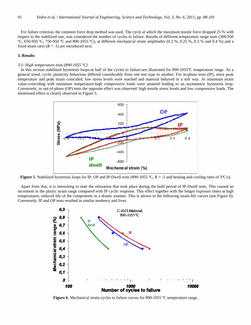
Apart from that, it is interesting to note the relaxation that took place during the hold period of IP Dwell tests. This caused an increment in the plastic strain range compared with IP cyclic response. This effect together with the longer exposure times at high temperatures, reduced life of the components in a drastic manner. This is shown in the following strain-life curves (see Figure 6). Conversely, IP and OP tests resulted in similar tendency and lives.
Figure 6. Mechanical strain-cycles to failure curves for 890-1055 ºC temperature range.

Yedra et al. / International Journal of Engineering, Science and Technology, Vol. 3, No. 6, 2011, pp. 88-101
92
This way of representing fatigue data is similar to the widely used Wöhler method (Wöhler, 1867) , in which the experimental data (number of cycles to failure) is plotted as a function of the stress amplitude (in low cycle fatigue the stress is replaced by the strain). In addition, in the case of thermo-mechanical fatigue, classifying graphs according to temperature range and phase shift is a common practice (Hopkins, 1976; Beck et al., 1997; Huang et al., 2006). This is due to the fact that different behaviours may arise at different conditions (as in this case). Another way of representing fatigue life data was introduced by Coffin and Manson (Manson, 1966), which is defined by the following power laws:
1b
e fC Nε −Δ = ⋅ (2)
and
2c
p fC Nε −Δ = ⋅ (3)
where Δεe and Δεp are the elastic and plastic strain ranges respectively, Nf stands for the number of cycles to failure and finally C1, C2, b and c are material constants. It was proved that, for a wide range of materials, b and c exponents were close to 0.12 and 0.5-0.7 values, respectively. It has to be pointed that at higher temperatures, curves tend to become steeper, as in this case. Those exponent values-c values from equation 3-are collected in Table 2, for C-1023 subjected to the already described conditions. Highest values were identified in IP Dwell tests with respect to the rest of phase angles, due to the more pronounced temperature effect.
Table 2. Exponent values (c) for 890-1055 ºC temperature range in C-1023.
c exponent for
C-1023
IP 0.946
OP 0.82
IP Dwell 1.44
The resultant plastic strain ranges for the given temperature range were large when compared to the mechanical strain range (the ratio is always higher than 0.3) and so was the plastic work compared to elastic work (a ratio of 0.5 was obtained in the case of IP Dwell tests). This energy or work was assessed for the entire batch of tests by calculating the following integral:
p pW dσ εΔ = ∫ (4)
This was done by numeric integration (trapezium rule) and using (σ, ε) pair values. The reference cycle, a stabilized cycle, was typically considered at half of the cycles to failure. The mentioned plastic work was highest in those cases where hold periods were applied (IP Dwell). In addition, slight differences were found between IP and OP configurations, being the energy dissipation slightly higher in the former case. This could be ascribed to creep strain accumulation at high temperatures coinciding with the highest tensile stresses. 3.2- Effects of reducing Tmin Different tests were accomplished by reducing Tmin
while the Tmax remained fixed: 300-950 ºC, 650-950 ºC and 750-950 ºC temperature ranges. The aim was to determine the influence of minimum temperature on the resulting life. From a practical point of view, this is an important aspect since turbines operating conditions vary from temperatures as low as room temperature to temperatures as high as 1055 ºC. The effect of reducing Tmin is shown in Figure 7. It is clearly observed that as the Tmin was reduced life of the test-pieces decreased.

Yedra et al. / International Journal of Engineering, Science and Technology, Vol. 3, No. 6, 2011, pp. 88-101
93
Figure 7. Tmin effect on TMF life in C-1023 material under IP test configuration
This may be explained by the higher modulus of elasticity at low temperatures, which results in higher compressive loads as well as an increase in the width of the hysteresis loop. In Figure 8 those hysteresis loops are depicted. Note that little differences were identified between 650 ºC and 750 ºC tests (in the later case the plastic strain range was slightly higher). This is due to their similar yield strength and modulus of elasticity. On the contrary, at 300 ºC an increase in the plastic strain range (1.4 times higher with respect to the rest of the temperature range) and in minimum stress occurred.
-800
-600
-400
-200
0
200
400
-0.3 -0.2 -0.1 0 0.1 0.2 0.3
Mechanical strain (%)
Stre
ss (M
Pa)
300-950ºC IP750-950 ºC IP650-950 ºC IP
Figure 8. Stabilized hysteresis loops for a fixed Tmax (950 ºC) and variable Tmin (300 ºC,650 ºC and 750 ºC).
Important aspects related to degradation mechanisms may be obtained from the cyclic response. That is the case of creep and stress relaxation, that is visible for the 300-950 ºC temperature range. As an example, maximum stress was not reached at maximum strain value, which is representative of the mentioned damage (see Figure 8). On the other hand, both maximum stress value and maximum strain coincided in the rest of the temperature ranges (750-950 ºC and 650-950 ºC) and also for the whole range of OP tests. Concerning the stress-strain response, it stabilized after few cycles (less than 10 cycles), during which limited softening occurred at Tmax, and hardening at Tmin regardless of the test-configuration (see Figure 9). That is, high temperatures enhanced softening and low temperatures hardening. Load drop, which gives an idea of the crack growth rate, was more abrupt in those tests with higher tensile stresses, that is, OP configurations.

Yedra et al. / International Journal of Engineering, Science and Technology, Vol. 3, No. 6, 2011, pp. 88-101
94
Figure 9. Maximum and minimum stress evolution in IP, OP and Diamond tests cycled between 650-950 ºC and 750-950 ºC It is remarkable from Figure 9 that those tests with the highest tensile stresses did not lead to the shortest cycles to failure. That is the case of IP lives, which were shorter than OP, in some cases, in spite of the low tensile stresses. This may be better explained by defining simple damage parameters and more precisely, by normalizing some cyclic parameters with respect to material resistance at the corresponding temperature. Further study is covered in the following section. 3.3- Life assessment It is common in engineering applications to rely on life prediction models based on semi-empirical approaches. Usually a parameter that best explained the behaviour of the material is correlated with the cycles to failure. In this work different parameters validity, such as dissipated energy per cycle, Ostergren parameter, Zamrik parameter etc. was studied for the data set obtained in the experimental chapter. a) Ostergren model It is an energy based life prediction model which considers that failure occurs due to the repeated tensile energy dissipation in a hysteresis loop (Ostergren, 1976). In order to consider the frequency dependency, f-1(Hz) parameter is also added. The aim was to predict life of the executed TMF tests regardless of the test-type (IP, OP, IP Dwell or Diamond). That is, a general damage parameter was sought with the following relation:
1maxf pC N fβ ε σ −= Δ (5)
where C and β are material constants, Δεp is the plastic strain range, σmax, is the maximum stress and f is the frequency of the cycle. The method fitted the experimental data almost in a band scatter equal to two of the unit correlation line (see Figure 10). As a general trend, predictions were over-estimated for IP configurations whereas in OP, results generally led to conservative estimations. This may suggests that the parameter did not capture all the effects occurring at different phase shifts, such as temperature effects. Some other authors (Beck et. al, 1997) found similar results. They stated that although for both cases, IP and OP, fatigue was the predominant mechanisms the contribution of thermally activated processes lowered IP lives. Unfortunately, Ostergren damage parameter does not capture the mentioned effects, since it simply considers the energy dissipated at tensile stresses. A much better prediction was obtained by simply correlating the plastic work with the experimental life using a power law (see Figure 11). This is also an energy based life prediction criteria and it leads to a scatter band very close to a factor of two. This would mean that energy dissipated at tensile stresses is not the unique responsible for failure, since better fitting is obtained taking into account the entire cycle. That is, two tests with equal tensile energy dissipation do not necessarily lead to same cycles to failure if their behaviour at compressive stresses is different. This could be related to crack closure.

Yedra et al. / International Journal of Engineering, Science and Technology, Vol. 3, No. 6, 2011, pp. 88-101
95
Figure 10. Actual cycles to failure vs. predicted values by the Ostergren parameter.
Figure 11. Actual cycles to failure vs. predicted values by plastic work.
b) Zamrik model This model may also be considered as an energy based life prediction method, similar to the one suggested by Ostergren. Nevertheless Zamrik tried to avoid the inelastic strain term due to the inaccuracies arisen when measuring it experimentally (mainly in small mechanical strain amplitudes tests). In these cases, typically no plastic strain occurs at a macroscopic scale or at least difficulties are arisen when measuring it. Instead of this parameter the maximum tensile stress and some other parameters are included. Equation 6 is the expression used by Zamrik (Zamrik et. al, 2000) for life assessment:
( ) ( ( )) ( ( ))z z z
Z
B C Df zN A W h t r T= Δ (6)
where Az, Bz,Cz and Dz are material constants.

Yedra et al. / International Journal of Engineering, Science and Technology, Vol. 3, No. 6, 2011, pp. 88-101
96
The term zWΔ stands for an energy function expressed as:
maxf tenz
t u f
WW
Wσ εσ ε
⋅Δ = =
⋅
(7)
where: σmax= maximum tensile stress in mid-life hysteresis loop. εten = tensile strain range in mid-life hysteresis loop for which the stress is tensile. σu = ultimate strength measured under monotonic tensile strength. εf = elongation to failure measured under monotonic tensile loading. The term h(t) is the hold-time function expressed by:
( ) 1 h
c
th tt
⎛ ⎞= +⎜ ⎟⎝ ⎠
(8)
where: th = length of the tensile hold-time. tc = length of total cycle time including hold-time. Finally, r(T)-the elevated temperature function-may be written as:
max
( ) exp( )
z
o
Qr TR T T
⎛ ⎞−= ⎜ ⎟−⎝ ⎠
(9)
where: Qz= activation energy for high temperature damage (J/mol) R= Raoult’s gas constant (8.31447 J/K⋅ mol) Tmax= maximum temperature in TMF cycle (ºC). T0 = temperature at which the yield strength of the material begins to decrease (ºC). The model resulted in poor estimations due to the fact that it did not provide higher accuracy than a band scatter equal to a factor of 3. However, it is interesting to note that the parameter that accounts for the tensile elastic energy (εtensile/εf) did not correlate as expected with the number of cycles to failure. On the other hand, if simply the σmax/ σu ratio is considered for the definition of ΔWz parameter (instead of the tensile elastic energy) the fitting improves considerably (see Figure 12). A coefficient of determination equal to 0.74 was achieved.
Yedra et al. / International Journal of Engineering, Science and Technology, Vol. 3, No. 6, 2011, pp. 88-101
97
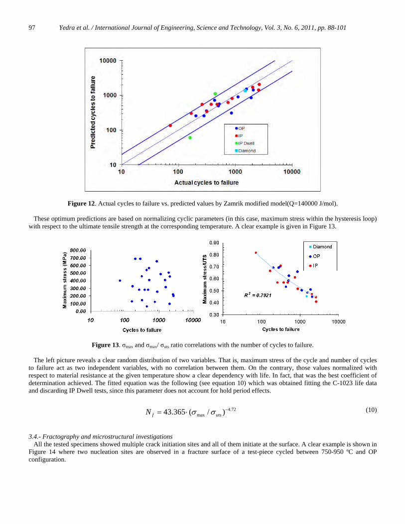
Figure 12. Actual cycles to failure vs. predicted values by Zamrik modified model(Q=140000 J/mol). These optimum predictions are based on normalizing cyclic parameters (in this case, maximum stress within the hysteresis loop) with respect to the ultimate tensile strength at the corresponding temperature. A clear example is given in Figure 13.
Figure 13. σmax and σmax/ σuts ratio correlations with the number of cycles to failure.
The left picture reveals a clear random distribution of two variables. That is, maximum stress of the cycle and number of cycles to failure act as two independent variables, with no correlation between them. On the contrary, those values normalized with respect to material resistance at the given temperature show a clear dependency with life. In fact, that was the best coefficient of determination achieved. The fitted equation was the following (see equation 10) which was obtained fitting the C-1023 life data and discarding IP Dwell tests, since this parameter does not account for hold period effects.
4.72max43.365 ( / )f utsN σ σ −= ⋅ (10)
3.4.- Fractography and microstructural investigations All the tested specimens showed multiple crack initiation sites and all of them initiate at the surface. A clear example is shown in Figure 14 where two nucleation sites are observed in a fracture surface of a test-piece cycled between 750-950 ºC and OP configuration.

Yedra et al. / International Journal of Engineering, Science and Technology, Vol. 3, No. 6, 2011, pp. 88-101
98
Figure. 14. Fracture surface of OP tests cycled between 750-950 ºC temperature range In some cases -mainly in OP tests, where the tensile stress was high- fatigue striations were clearly observed and also the increase in the spacing among them, as crack moved away from the surface (see Figure 15). This was a clear indication of crack growth rate increase with the stress intensity factor increment.
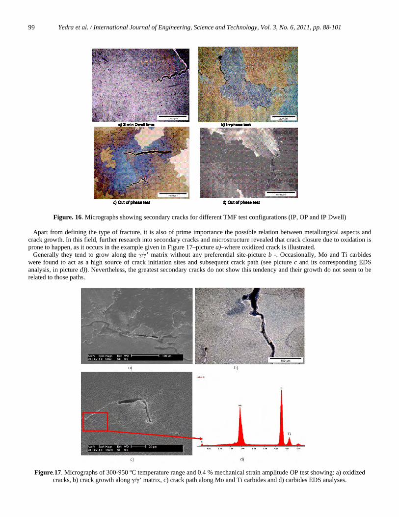
Figure. 15. Fatigue striations in a OP test (Δεm/2 = 0.4% and 300-950 ºC) In Figure 16 micrographs showing secondary cracks for different TMF test configurations (IP, OP and IP Dwell) are illustrated. These micrographs were taken close to the place where test-piece rupture occurred. It is clearly observed that in IP and IP Dwell tests crack growth was due to grain boundaries sliding and intergranular cracking (pictures a and b), that is to say creep damage. Conversely, in out-of-phase tests cracks grow in a transgranular manner -related to fatigue damage-, even though depending on the tested parameters (frequency, temperature range…) a mixed mode or even intergranular cracking may appear (see picture d).
Crack growth
Yedra et al. / International Journal of Engineering, Science and Technology, Vol. 3, No. 6, 2011, pp. 88-101
99
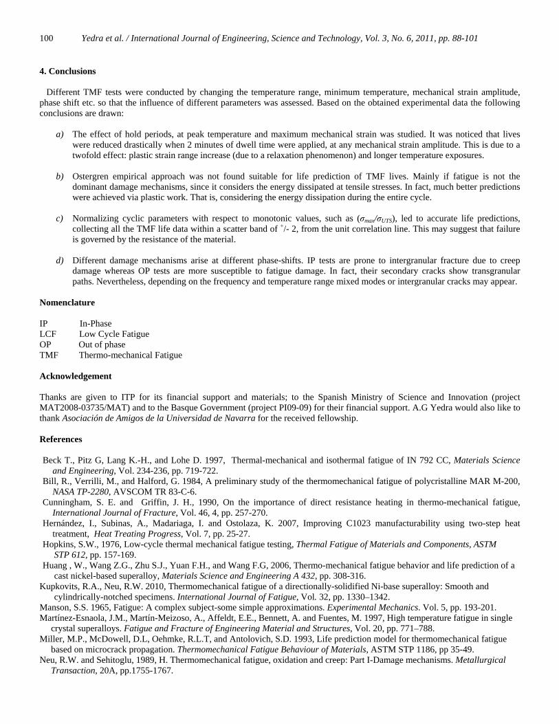
Figure. 16. Micrographs showing secondary cracks for different TMF test configurations (IP, OP and IP Dwell) Apart from defining the type of fracture, it is also of prime importance the possible relation between metallurgical aspects and crack growth. In this field, further research into secondary cracks and microstructure revealed that crack closure due to oxidation is prone to happen, as it occurs in the example given in Figure 17–picture a)–where oxidized crack is illustrated. Generally they tend to grow along the γ/γ’ matrix without any preferential site-picture b -. Occasionally, Mo and Ti carbides were found to act as a high source of crack initiation sites and subsequent crack path (see picture c and its corresponding EDS analysis, in picture d)). Nevertheless, the greatest secondary cracks do not show this tendency and their growth do not seem to be related to those paths.
Figure.17. Micrographs of 300-950 ºC temperature range and 0.4 % mechanical strain amplitude OP test showing: a) oxidized cracks, b) crack growth along γ/γ’ matrix, c) crack path along Mo and Ti carbides and d) carbides EDS analyses.
Yedra et al. / International Journal of Engineering, Science and Technology, Vol. 3, No. 6, 2011, pp. 88-101
100
4. Conclusions Different TMF tests were conducted by changing the temperature range, minimum temperature, mechanical strain amplitude, phase shift etc. so that the influence of different parameters was assessed. Based on the obtained experimental data the following conclusions are drawn:
a) The effect of hold periods, at peak temperature and maximum mechanical strain was studied. It was noticed that lives were reduced drastically when 2 minutes of dwell time were applied, at any mechanical strain amplitude. This is due to a twofold effect: plastic strain range increase (due to a relaxation phenomenon) and longer temperature exposures.
b) Ostergren empirical approach was not found suitable for life prediction of TMF lives. Mainly if fatigue is not the
dominant damage mechanisms, since it considers the energy dissipated at tensile stresses. In fact, much better predictions were achieved via plastic work. That is, considering the energy dissipation during the entire cycle.
c) Normalizing cyclic parameters with respect to monotonic values, such as (σmax/σUTS), led to accurate life predictions,
collecting all the TMF life data within a scatter band of +/- 2, from the unit correlation line. This may suggest that failure is governed by the resistance of the material.
d) Different damage mechanisms arise at different phase-shifts. IP tests are prone to intergranular fracture due to creep
damage whereas OP tests are more susceptible to fatigue damage. In fact, their secondary cracks show transgranular paths. Nevertheless, depending on the frequency and temperature range mixed modes or intergranular cracks may appear.
Nomenclature IP In-Phase LCF Low Cycle Fatigue OP Out of phase TMF Thermo-mechanical Fatigue Acknowledgement
Thanks are given to ITP for its financial support and materials; to the Spanish Ministry of Science and Innovation (project MAT2008-03735/MAT) and to the Basque Government (project PI09-09) for their financial support. A.G Yedra would also like to thank Asociación de Amigos de la Universidad de Navarra for the received fellowship. References
Beck T., Pitz G, Lang K.-H., and Lohe D. 1997, Thermal-mechanical and isothermal fatigue of IN 792 CC, Materials Science
and Engineering, Vol. 234-236, pp. 719-722. Bill, R., Verrilli, M., and Halford, G. 1984, A preliminary study of the thermomechanical fatigue of polycristalline MAR M-200,
NASA TP-2280, AVSCOM TR 83-C-6. Cunningham, S. E. and Griffin, J. H., 1990, On the importance of direct resistance heating in thermo-mechanical fatigue,
International Journal of Fracture, Vol. 46, 4, pp. 257-270. Hernández, I., Subinas, A., Madariaga, I. and Ostolaza, K. 2007, Improving C1023 manufacturability using two-step heat
treatment, Heat Treating Progress, Vol. 7, pp. 25-27. Hopkins, S.W., 1976, Low-cycle thermal mechanical fatigue testing, Thermal Fatigue of Materials and Components, ASTM STP 612, pp. 157-169. Huang , W., Wang Z.G., Zhu S.J., Yuan F.H., and Wang F.G, 2006, Thermo-mechanical fatigue behavior and life prediction of a cast nickel-based superalloy, Materials Science and Engineering A 432, pp. 308-316.
Kupkovits, R.A., Neu, R.W. 2010, Thermomechanical fatigue of a directionally-solidified Ni-base superalloy: Smooth and cylindrically-notched specimens. International Journal of Fatigue, Vol. 32, pp. 1330–1342.
Manson, S.S. 1965, Fatigue: A complex subject-some simple approximations. Experimental Mechanics. Vol. 5, pp. 193-201. Martínez-Esnaola, J.M., Martín-Meizoso, A., Affeldt, E.E., Bennett, A. and Fuentes, M. 1997, High temperature fatigue in single crystal superalloys. Fatigue and Fracture of Engineering Material and Structures, Vol. 20, pp. 771–788. Miller, M.P., McDowell, D.L, Oehmke, R.L.T, and Antolovich, S.D. 1993, Life prediction model for thermomechanical fatigue based on microcrack propagation. Thermomechanical Fatigue Behaviour of Materials, ASTM STP 1186, pp 35-49. Neu, R.W. and Sehitoglu, 1989, H. Thermomechanical fatigue, oxidation and creep: Part I-Damage mechanisms. Metallurgical Transaction, 20A, pp.1755-1767.

Yedra et al. / International Journal of Engineering, Science and Technology, Vol. 3, No. 6, 2011, pp. 88-101
101
Ostergren, W. J., 1976, A damage function and associated failure equations for predicting hold time and frequency effects in elevated temperature, low cycle fatigue, ASTM Journal of Testing and Evaluation, Vol. 4, pp. 327-339.
Pollock, T.M. and Tin, S. 2006, Nickel-based superalloys for advanced turbine engines: chemistry, microstructure, and properties, Journal of Propulsion and Power, Vol. 22, No. 2. Thomas K., Heckel, T. and Hans-Jürgen C. 2010, Isothermal and thermomechanical fatigue of titanium alloys. Procedia Engineering, Vol. 2, pp. 845-854. Wöhler, M.,1867, Wöhler's experiment on the strength of metals, Engineering, Vol. 4 , pp. 160–161. Zamrik, S. Y., and Renauld, 2000, Thermo-mechanical out-of-phase fatigue life of overlay coated IN738-LC gas turbine material,
Thermomechanical Fatigue Behavior of Materials, ASTM, STP 1371, pp. 119–137. Biographical notes Dr. A. García de la Yedra received Mechanical Engineering degree from the Basque University (UPV) and Ph. D. degree from the University of Navarra (Spain) in 2011. He is an assistant professor at the Materials Department. His main areas of research are materials behaviour at high temperature, fatigue & fracture, and fracture mechanics. Prof. A. Martín-Meizoso got his doctorate in Naval Architecture at the Polytechnic University of Madrid. He is a Senior Researcher in the Materials Department at CEIT (Spain) and a Full Professor at Tecnun-University of Navarra, where he lectures in the Mechanical Engineering and Materials Engineering departments. Currently, he is the President for the Spanish Association of Structural Integrity and the Spanish Group on Fracture. He has published over 40 papers in international journals (quoted in the SCI), 12 in national journals, 102 contributions to congresses and conferences and 14 textbooks. Dr. R. Rodríguez Martín received Chemistry degree from the Basque University (UPV) and Ph. D. degree from the University of Navarra (Spain). Her research interests are metallurgy, fatigue, and fracture where she owns a great experience. She is also a Professor in the Materials Department where she has more than 5 years of experience in Materials Science lectures. J.L. Pedrejón received Technical Engineering degree from the Mondragón University (Spain). He has participated in several research projects funded by the Spanish Government, most of them related to high temperature fatigue. Received May 2011 Accepted October 2011 Final acceptance in revised form October 2011