ThermalStorageCapacityandNightVentilationPerformanceofa Solar Chimney...
11
Research Article Thermal Storage Capacity and Night Ventilation Performance of a Solar Chimney Combined with Different PCMs Jun Lu, Xiaolong Gao, Qianru Li, and Yongcai Li Key Laboratory of the Three Gorges Reservoir Region’s Eco-Environment, Ministry of Education, Chongqing University, Chongqing, China Correspondence should be addressed to Yongcai Li; [email protected] Received 8 February 2017; Revised 5 April 2017; Accepted 22 May 2017; Published 5 July 2017 Academic Editor: Alibakhsh Kasaeian Copyright © 2017 Jun Lu et al. This is an open access article distributed under the Creative Commons Attribution License, which permits unrestricted use, distribution, and reproduction in any medium, provided the original work is properly cited. Thermal storage capacity and airflow rate of a solar chimney combined with different PCMs are numerically studied during nighttime. PCMs with phase change temperatures of 38 ° C, 44 ° C, 50 ° C, and 63 ° C are selected in this numerical study. Results show that the maximum average ventilation rate of 610 kg/m 2 and maximum thermal storage of 4750 kJ/m 2 are achieved at the phase change temperature of 38 ° C. However, for phase change temperature of 63 ° C, night ventilation does not occur under the identical conditions. The findings reveal that a lower phase change temperature can increase the chargeability (and therefore the dischargeability) of a solar chimney, since a higher phase change temperature demands higher solar radiation intensity and longer charging time for a solar chimney. For PCM with a phase change temperature of 44 ° C, most of the heat stored in PCM is lost to ambient through glass cover by radiation and only a small portion is used for heating the air within air channel. 1. Introduction A solar chimney is a natural draft system that has already been applied in the building ventilation widely and has attracted the interest of many scholars around the world. Extensive numerical or/and experimental studies in terms of evaluating ventilation performance [1–5] and optimizing design of solar chimney [6–10] have been performed. A solar chimney consisted of roof solar collector, and Trombe wall was experimentally investigated by Khedari et al. [11]. Results show that in June~July of a hot and humid cli- mate, the temperature, air velocity, and flow rate per area of a solar chimney inside the room varies from 35–37 ° C, 0.02–0.08 m/s, and 0.01–0.02 m 3 /s per 1m 2 , respectively. Hirunlabh et al. [12] performed a numerical study on four new configurations of roof solar collector under Thailand weather conditions. By using the new configuration of roof solar collector, the highest volume flow rate of air is 0.072 m 3 /s or 0.0206 m 3 /s per 1m 2 of a solar chimney. Chungloo and Limmeechokchai found that with a solar chimney, the indoor temperature can be reduced by 1.0– 3.5 ° C at high ambient temperature and high solar intensity (32.0–40.01 ° C) in the daytime [13]. Miyazaki et al. [14] numerically investigated the effects of solar chimneys on thermal load mitigation of office buildings in Japan. The results showed that in the natural ventilation mode, a larger chimney area was required to reduce the passive cooling load of the building. Between 10 a.m. and 12 p.m. of an average day in May, when the chimney width is 4 m, the cooling load was less than that of the no solar chimney design. Studies reveal that the height [6], chimney position [7], type of absorber [8], width and depth of cavity [15], inclina- tion angle [16], and the insulation or thermal mass in the solar chimney [17] are the primary factors that should be considered when designing a solar chimney. The above anal- ysis indicated that solar chimney possesses the potential of cooling effect and cooling load reduction, and the potential can be enhanced by optimizing the designing factors. The available studies mainly concentrated on the performance characteristics of solar chimney during the daytime. If the night ventilation or all-day ventilation can be achieved, the solar energy utilization as well as the indoor thermal comfort would be greatly improved. Amori and Mohammed [18] Hindawi International Journal of Photoenergy Volume 2017, Article ID 8363190, 10 pages https://doi.org/10.1155/2017/8363190
Transcript of ThermalStorageCapacityandNightVentilationPerformanceofa Solar Chimney...
Research ArticleThermal Storage Capacity and Night Ventilation Performance of aSolar Chimney Combined with Different PCMs
Jun Lu, Xiaolong Gao, Qianru Li, and Yongcai Li
Key Laboratory of the Three Gorges Reservoir Region’s Eco-Environment, Ministry of Education, Chongqing University,Chongqing, China
Correspondence should be addressed to Yongcai Li; [email protected]
Received 8 February 2017; Revised 5 April 2017; Accepted 22 May 2017; Published 5 July 2017
Academic Editor: Alibakhsh Kasaeian
Copyright © 2017 Jun Lu et al. This is an open access article distributed under the Creative Commons Attribution License, whichpermits unrestricted use, distribution, and reproduction in any medium, provided the original work is properly cited.
Thermal storage capacity and airflow rate of a solar chimney combined with different PCMs are numerically studied duringnighttime. PCMs with phase change temperatures of 38°C, 44°C, 50°C, and 63°C are selected in this numerical study. Resultsshow that the maximum average ventilation rate of 610 kg/m2 and maximum thermal storage of 4750 kJ/m2 are achieved at thephase change temperature of 38°C. However, for phase change temperature of 63°C, night ventilation does not occur under theidentical conditions. The findings reveal that a lower phase change temperature can increase the chargeability (and therefore thedischargeability) of a solar chimney, since a higher phase change temperature demands higher solar radiation intensity andlonger charging time for a solar chimney. For PCM with a phase change temperature of 44°C, most of the heat stored in PCM islost to ambient through glass cover by radiation and only a small portion is used for heating the air within air channel.
1. Introduction
A solar chimney is a natural draft system that has alreadybeen applied in the building ventilation widely and hasattracted the interest of many scholars around the world.Extensive numerical or/and experimental studies in termsof evaluating ventilation performance [1–5] and optimizingdesign of solar chimney [6–10] have been performed. A solarchimney consisted of roof solar collector, and Trombe wallwas experimentally investigated by Khedari et al. [11].Results show that in June~July of a hot and humid cli-mate, the temperature, air velocity, and flow rate per areaof a solar chimney inside the room varies from 35–37°C,0.02–0.08m/s, and 0.01–0.02m3/s per 1m2, respectively.Hirunlabh et al. [12] performed a numerical study on fournew configurations of roof solar collector under Thailandweather conditions. By using the new configuration of roofsolar collector, the highest volume flow rate of air is0.072m3/s or 0.0206m3/s per 1m2 of a solar chimney.Chungloo and Limmeechokchai found that with a solarchimney, the indoor temperature can be reduced by 1.0–3.5°C at high ambient temperature and high solar intensity
(32.0–40.01°C) in the daytime [13]. Miyazaki et al. [14]numerically investigated the effects of solar chimneys onthermal load mitigation of office buildings in Japan. Theresults showed that in the natural ventilation mode, alarger chimney area was required to reduce the passivecooling load of the building. Between 10 a.m. and 12 p.m.of an average day in May, when the chimney width is4m, the cooling load was less than that of the no solarchimney design.
Studies reveal that the height [6], chimney position [7],type of absorber [8], width and depth of cavity [15], inclina-tion angle [16], and the insulation or thermal mass in thesolar chimney [17] are the primary factors that should beconsidered when designing a solar chimney. The above anal-ysis indicated that solar chimney possesses the potential ofcooling effect and cooling load reduction, and the potentialcan be enhanced by optimizing the designing factors. Theavailable studies mainly concentrated on the performancecharacteristics of solar chimney during the daytime. If thenight ventilation or all-day ventilation can be achieved, thesolar energy utilization as well as the indoor thermal comfortwould be greatly improved. Amori and Mohammed [18]
HindawiInternational Journal of PhotoenergyVolume 2017, Article ID 8363190, 10 pageshttps://doi.org/10.1155/2017/8363190
experimentally investigated the effect of integrating phasechange material (PCM) in a solar chimney and found thatintegrating a solar chimney with PCM yield longer ventila-tion period after the sunset. In this paper, a PCM unit is inte-grated into the solar absorber of the chimney to takeadvantage of PCM’s isothermal phase change characteristicas well as high latent heat density. The PCM absorbs the heatradiated from the sun and stores heat during the daytime andthen releases the absorbed heat during the nighttime. By thismeans, night ventilation can be achieved without consumingany additional energy sources. This has been indicated by Liuand Li’s study [19], in which the performance of a conven-tional vertical solar chimney and a PCM-based one withthe same geometry was compared. In their study, the paraffinwax with phase change temperature of 38–42°C was selectedas PCM. It was found that the effective ventilation time of thePCM-based solar chimney can be as long as 13 h 50min,while the conventional one’ ventilation time is only 1 h20min. Similarly, Zhou and Pang [20] experimentallystudied the thermal behavior of a system with a collector-storage wall using PCM with phase change temperature26± 1°C. The experimental results indicated that by inte-grating PCM in the wall, the whole ventilation period ofthe system is as long as 17.5 h.
It is should be noticed that the PCM can significantlyinfluence the ventilation performance of the PCM-basedsolar chimney, especially the phase change temperatureof the PCM, which is a vital factor among the physicalproperties of the PCM. It directly affects the absorber tem-perature and consequently affects the air flow rate andthermal storage capacity.
Based on the findings from above literatures, a mathe-matical model is developed to examine the ventilation perfor-mance and thermal storage capacity of a solar chimney usingdifferent PCMs under hot summer climatic conditions. Theresults of this paper could help to enhance the performanceof such a PCM-based solar chimney by optimizing the phasechange temperature.
2. Description of Mathematical Model
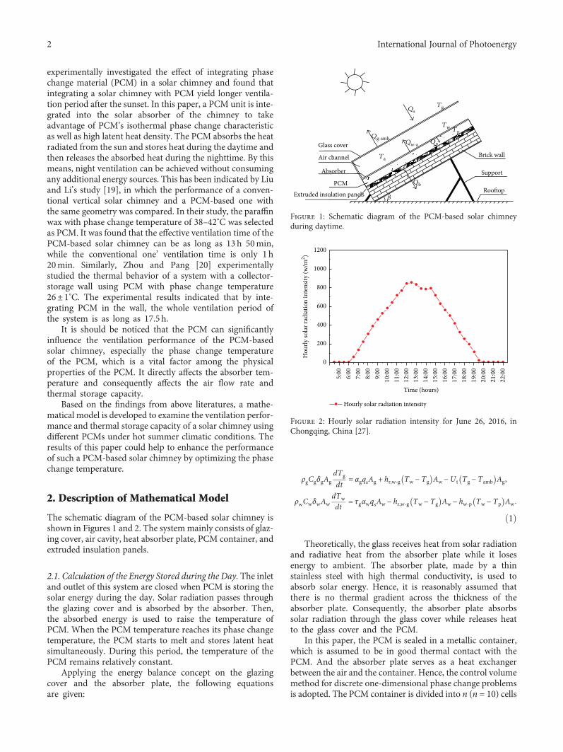
The schematic diagram of the PCM-based solar chimney isshown in Figures 1 and 2. The systemmainly consists of glaz-ing cover, air cavity, heat absorber plate, PCM container, andextruded insulation panels.
2.1. Calculation of the Energy Stored during the Day. The inletand outlet of this system are closed when PCM is storing thesolar energy during the day. Solar radiation passes throughthe glazing cover and is absorbed by the absorber. Then,the absorbed energy is used to raise the temperature ofPCM. When the PCM temperature reaches its phase changetemperature, the PCM starts to melt and stores latent heatsimultaneously. During this period, the temperature of thePCM remains relatively constant.
Applying the energy balance concept on the glazingcover and the absorber plate, the following equationsare given:
ρgCgδgAgdTgdt
= αgqsAg + hr,w‐g Tw − Tg Aw −U t Tg − Tamb Ag,
ρwCwδwAwdTwdt
= τgαwqsAw − hr,w‐g Tw − Tg Aw − hw‐p Tw − Tp Aw
1
Theoretically, the glass receives heat from solar radiationand radiative heat from the absorber plate while it losesenergy to ambient. The absorber plate, made by a thinstainless steel with high thermal conductivity, is used toabsorb solar energy. Hence, it is reasonably assumed thatthere is no thermal gradient across the thickness of theabsorber plate. Consequently, the absorber plate absorbssolar radiation through the glass cover while releases heatto the glass cover and the PCM.
In this paper, the PCM is sealed in a metallic container,which is assumed to be in good thermal contact with thePCM. And the absorber plate serves as a heat exchangerbetween the air and the container. Hence, the control volumemethod for discrete one-dimensional phase change problemsis adopted. The PCM container is divided into n (n = 10) cells
Glass coverQg-amb
Ta
Qb
�훽
Qw-a
Tw Tp
Brick wall
Support
Roo�op
Qp
QsTg
Air channel
Absorber
PCMExtruded insulation panels
Figure 1: Schematic diagram of the PCM-based solar chimneyduring daytime.
1200
1000
Hourly solar radiation intensity
800
600
400
200
Hou
rly so
lar r
adia
tion
inte
nsity
(w/m
2 )
0
5:00
6:00
7:00
8:00
9:00
10:0
011
:00
12:0
013
:00
14:0
0
Time (hours)
15:0
016
:00
17:0
018
:00
19:0
020
:00
21:0
022
:00
Figure 2: Hourly solar radiation intensity for June 26, 2016, inChongqing, China [27].
2 International Journal of Photoenergy
along the thickness direction. The one-dimensional energyequation for each internal node “i” can be written as follows:
ρpCpdxAwdTp,idt
= hw‐p Tw − Tp,i Aw −kpdx
Tp,i − Tp,i+1 Aw
i = 1,
ρpCpdxAwdTp,idt
=kpdx
Tp,i−1 − Tp,i Aw −kpdx
Tp,i − Tp,i+1 Aw
i = 2, 3,…, n− 1,
ρef fCef fdxAwdTp i
dt= κef f
dxTp i−1 − Tp i Aw −U ins Tp i − Tamb Aw
i = n,
ρpCpdxAwdTp,idt
=kpdx
Tp,i−1 − Tp,i Aw −Ub Tp,i − Tamb Aw
i = n
2
The heat transfer between different components ofthis system is shown in Figure 1, where qs is the solarradiation intensity.
(1) The thermal storage capacity of the PCM
qx = qw‐p − qb 3
(2) The radiative heat transfer coefficient between theabsorber and glass cover has been obtained from [21]
hr,w‐g =σ Tw
2 + Tg2 Tw + Tg
ξw−1 + ξg
−1 − 14
(3) The overall heat loss coefficient from the glass coverto ambient U t includes the convection caused bywind and radiative heat transfer from glass cover tosky. It can be written as
U t = hr,g‐sky + hwind 5
The radiative heat transfer coefficient from the glasscover to the sky may be obtained from [21]
hr,g‐sky =σξg Tg + Tsky Tg
2 + Tsky2 Tg − Tsky
Tg − Tamb6
The sky temperature Tsky and the convective heattransfer coefficient between the glazing cover and the sur-rounding air, which is affected by wind speed, can be calcu-lated by [21, 22]
Tsky = 0 0552Tamb,hwind = 2 8 + 3 0Vwind
7
(4) The overall heat transfer coefficient between thePCM and the absorber plate hw‐p is given by
hw‐p =1
δw/kw + dx/2k ,
qw‐p = hw‐p Tw − Tp
8
(5) The heat that the PCM transfers to indoor is given by
qb =Ub Tp − Tamb ,
Ub =1
1/hi + Δw1/kw1 + Δw2/kw29
2.2. Calculation of the Air Flow Rate during the Night. Thedischarging period begins when the chimney starts ventilat-ing during the night. The air exchanges heat with theabsorber plate as it passes through the air channel and thenflows to ambient through the outlet. For various componentsof the system, the energy balance equations for the dischar-ging period are presented below.
Applying the energy balance concept on the glass cover,absorber plate, and air flow in the air channel, the followingequations are yielded:
ρgCgδgAgdTgdt
= hr,w‐g Tw − Tg Aw + hcv,a‐g Ta − Tg Ag
−U t Tg − Tamb Ag,
ρwCwδwAwdTwdt
= hp‐w Tp − Tw Aw − hr,w‐g Tw − Tg Aw
− hcv,w‐a Tw − Ta Aw,
ρaCaVadTadt
= hcv,w‐a Tw − Ta Aw − hcv,a‐g Ta − Tg Ag
−mCa Tout − T in
10
Assuming that the natural convection of the air occursbetween the glazing cover and the absorber plate, the convec-tive heat transfer coefficient hcv,a-g between the glazing coverand the air in the channel can be calculated as follows [23]:
hcv,a‐g = hcv,w‐a =Nuλaδa
,
Nu = 0 06− 0 017 β/90 Gr1/3,11
where β is the inclination angle of the absorber plate (β = 90°in this study) and the Grashof number is
Gr =g Tw − Tg δ
3a
v2Ta12
It is assumed that the mean air temperature inside thechimney is equal to the average value of the absorber temper-ature and the glazing cover temperature at the absorber side.
Ta =Tw + Tg
2 13
3International Journal of Photoenergy

The relationship between inlet air temperature and outletair temperature can be described as follows [24, 25]:
Ta = γT in + 1− γ Tout, 14
where γ, the mean temperature approximation coefficient,was found in the literature to be 0.74 [21, 22] and theinlet air temperature T in can be regarded as the outdoorair temperature.
The airflow rate as a result of the buoyancy effect can becalculated as follows [26]:
m = CdρaAout
1 + A2r
2gsinβL TaT in
− 1 , 15
where Cd is found in the literature to be 0.57 [26].
Ca = 1007 + 0 04 Ta − 300 16
During the daytime, the initial state of all the PCM isin its solid phase and the whole system’s temperature isassumed to be the same as the ambient temperature. Forthe night ventilation period, the temperature of each sys-tem component and the PCM temperature depend onthe final charging conditions. The inlet air temperature isequal to the ambient temperature. The temperatures ofTw, Tg, Tp, and Ta as well as the airflow rate are obtainedwith a program solved in “MATLAB.” The air outlet temper-ature To can be obtained with the mean air temperatureand (14). With the developed code, the performance ofthe PCM-based solar chimney as well as the heat transferbetween various components of the solar chimney hasbeen investigated.
3. Analysis and Discussion of the NumericalResults
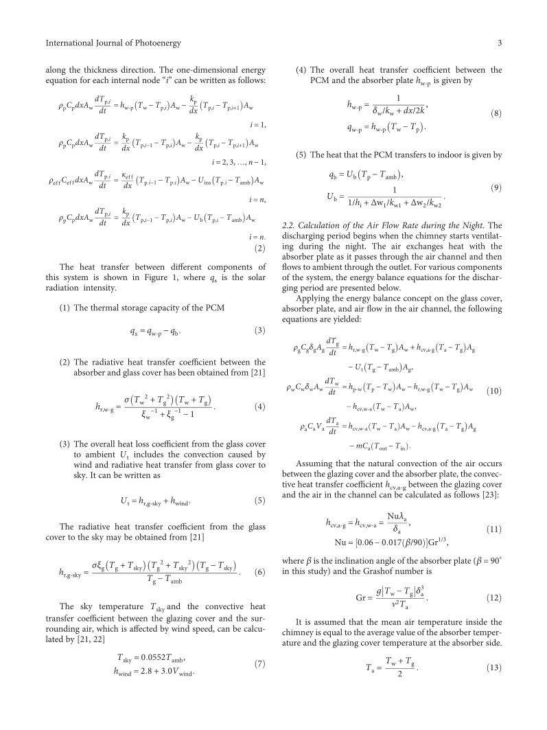
The input parameters of the proposed system are given inTables 1 and 2. The ventilation time is scheduled for19:00–7:00. The monthly average solar radiation at thehorizontal in Chongqing, China is close to the total solarradiation of June, and the solar radiation on June 26approaches to the daily average solar radiation of June.Therefore, the climatic parameters of June 26 in Chongqingobtained from [27] are applied in this study, and the solarradiation intensity is given in Figure 2.
This paper analyzes the effect of phase change tempera-ture on the ventilation rate of a solar chimney under Chong-qing climatic conditions. The PCMs used in this numericalstudy are myristoyl, dodecylic acid, myristelaidic acid, andpalmitic acid, and their corresponding phase change temper-atures are 38°C, 44°C, 50°C, and 63°C, respectively.
Figure 3 shows the stored energy and ventilation ratefor different PCMs. It is seen that the higher the phasechange temperature, the lower the energy storage and theventilation rate per unit area of absorber. That is to say,the PCM with phase change temperature of 38°C has thebest performance among the studied PCMs, while thePCM with phase change temperature of 63°C has thepoorest performance. Specifically, for the PCM with phase
change temperature of 38°C, the solar chimney achievesthe maximum energy storage of 4750 kJ/m2 and themaximum ventilation rate of 610 kg/m2. However, for thePCM with phase change temperature of 63°C, there is littleenergy stored in PCM, and consequently the airflow is notobserved during 19:00–07:00.
Figure 4 shows the absorber temperature and the PCMtemperature for four different PCMs when storing heat dur-ing daytime. As shown, the thermal behavior characteristicsof PCM under the identical conditions are different. Thetemperature variations of PCM display a typical fully charg-ing process for phase change temperatures of 38°C and 44°C,respectively. The melting times for these two PCMs are 5 and7.5 h, respectively. However, for the phase change tempera-tures of 50 and 63°C, the maximum PCM temperatures is49.6°C and 53°C at the end of charging process accordingly,indicating that PCMs are not fully melting. Especially forphase change temperature of 63°C, the PCM temperatureeven decreases after the peak solar radiation intensity. Thisis because the absorber surface temperature descends quicklywith solar radiation intensity weakens due to the high surfacetemperature. Consequently, the sensible heat stored in PCMtransfers to the absorber surface.
This indicates that a lower phase change temperature canincrease the chargeability and dischargeability of the solarchimney. The larger amount of energy stored and dischargedby the solar chimney and consequently a higher ventilationrate is achieved. A higher phase change temperaturedemands higher solar radiation intensity and longer chargingtime and results in poor chargeability of the chimney.
Figures 5–7 show the variations of air temperature andthe transient ventilation rate with time.
It can be seen from Figures 5–7 that the changing trend ofventilation rate is similar to that of the air temperature
Table 1: Specifications of the solar chimney and the thermo-physical properties of PCM.
Cover
Material Glass
Dimension 1500× 1000× 8mm
Surface coating 0.90
Absorber
Plate Aluminum
Thickness 2mm
Surface coating 0.94
PCMs
MyristoylDodecylic acid
Myristelaidic acidPalmitic acid
Melting temperature 38°C, 44°C, 50°C, 63°C
Thickness of PCM 40mm
Gap
Absorber plate to glass 200mm
Insulation material
Extruded insulation panels 30mm
4 International Journal of Photoenergy

difference between inlet and outlet. Higher phase changetemperature leads to poor chargeability of the chimney andhas the shorter ventilation time. The ventilation times corre-sponding to different PCMs are shown in Table 3.
As shown in Table 3, when the phase change temperatureof the PCM is 38°C, the longest ventilation time of 12 hourswas achieved while the PCM with phase change temperatureof 50°C has the shortest ventilation time which is only 4.33hours. This is because more solar energy was stored in thePCM with lower phase change temperature.
Figures 8 and 9 show the energy storage and release ofdifferent components of chimney combined with thedodecylic acid (phase change temperature of 44°C) duringthe day and night, respectively.
It can be seen from Figure 8 that the available solarenergy Qs is as high as 11,000 kJ/m2, while the energy storedin PCM Qx is only 3150 kJ/m
2, which accounts for 28.6% ofthe Qs. The heat transferred by radiation from glass coverto ambient Qg‐amb is 5090 kJ/m2 that accounts for 46.3% ofQs. It means that nearly 50% of the solar energy is lostthrough glass cover to ambient during the daytime period.The solar energy utility efficiency is still low for PCM ofdodecylic acid.
It can be seen from Figure 9 that most of energy stored inPCM is transferred to absorber surface, Qp‐w accounts for
89% of Qx. However, 80% of Qp‐w loses to ambient throughglass cover during night ventilation. The heat absorbed byair Qa is only about 13% of Qx. This means that most of heatstored in PCM is lost to ambient through glass cover by radi-ation during the night ventilation; only a small portion isused for heating the air within air channel.
4. Validation of the Numerical Model
The numerical model is validated by comparing numericalpredictions of PCM temperature and air mass flow ratewith the experimental results obtained from Liu and Li’sstudy [28]. This experiment investigated the thermal per-formance of a solar chimney integrated with PCM for agiven heat flux. The PCM temperature during chargingand discharging processes and air flow rate were investi-gated. As shown in Figure 10, a rectangular PCM con-tainer with dimensions of 1000mm wide× 1600mmhigh× 40mm deep was constructed of stainless steel. Atotal of 50 kg RT42 was used to fill the container, andthe physical properties of RT42 was given in [28]. In theirexperimental testing, the openings of inlet and outlet wereclosed during the charging period. The discharging periodhappened right after the charging period. A number of K-type thermocouples with the measurement range of −50 to
Table 2: Initial conditions for numerical modelling.
Item Value Item Value Item Value
αg 0.06 Kw2, Wm−1 K−1 0.028 υ, m2 s−1 19.5× 10⁻⁶
αw 0.94 ρg, kgm−3 2526 Uw, Wm−2 K−1 26
τg 0.84 ρw, kgm−3 2730 hi, Wm−2 K−1 4.55
σ, Wm−2 K−4 5.67× 10⁻⁸ ρp, kgm−3 1007 Aout, m
2 0.2
λa 0.028 Cg, Jkg−1 K−1 837 Ain, m
2 0.2
δa, m 0.3 Cw, Jkg−1 K−1 880 νm, m
2 s−1 17.5× 10⁻⁶
Δw1, m 0.3 Vg, m3 0.012 Pr 0.7
Δw2, m 0.03 Vw, m3 0.003 C 0.57
Hea
t sto
rage
capa
city
(KJ/m
2 )
5000
4000
3000
2000
1000
038ºC 44ºC 50ºC
PCM63ºC
0
100
200
300
400
500
600
700
Vent
ilatio
n ra
te (K
g/m
2 )
800
Ventilation rateHeat storage capacity
Figure 3: Thermal storage capacity and air flow rate for four different PCMs.
5International Journal of Photoenergy

250°C and accuracy of ±0.3°C were distributed on theglass cover, absorber plate, inside the PCM, and the airchannel. Air velocities inside the air channel are mea-sured by a TSI8455 air flow probe with the measurement
range of 0–50m/s and accuracy of ±3% of reading. Thesetup of the developed model in this study follows theexperimental conditions. Figure 11(a) shows the PCMtemperatures obtained by numerical simulation andexperiment testing. It can be seen that there was a good
07:0
0
Time (hours)
Transient ventilation rateAir temperature di�erence
19:0
0
21:0
020
:00
22:0
023
:00
00:0
001
:00
02:0
003
:00
04:0
005
:00
06:0
0
10 0.12
0.10
0.08
0.06
0.04
0.02
0.00
8
6
4
2
0
Air
tem
pera
ture
di�
eren
ce (º
C)
Tran
sient
ven
tilat
ion
rate
(Kg/
s)
Figure 5: Variation of air temperature and ventilation rate for phasechange temperature of 38°C.
8075706560555045
Tem
pera
ture
(ºC)
403530
7:00
8:00
9:00
10:0
011
:00
12:0
013
:00
Time (hours)
14:0
038ºC PCM temperatureAbsorber temperature
15:0
016
:00
17:0
018
:00
19:0
0
(a)
8075706560555045
Tem
pera
ture
(ºC)
403530
7:00
8:00
9:00
10:0
011
:00
12:0
013
:00
Time (hours)
14:0
0
44ºC PCM temperatureAbsorber temperature
15:0
016
:00
17:0
018
:00
19:0
0
(b)
75706560555045
Tem
pera
ture
(ºC)
403530
7:00
8:00
9:00
10:0
011
:00
12:0
013
:00
Time (hours)
14:0
0
50ºC PCM temperatureAbsorber temperature
15:0
016
:00
17:0
018
:00
19:0
0
(c)
75706560555045
Tem
pera
ture
(ºC)
403530
7:00
8:00
9:00
10:0
011
:00
12:0
013
:00
Time (hours)
14:0
0
63ºC PCM temperatureAbsorber temperature
15:0
016
:00
17:0
018
:00
19:0
0
(d)
Figure 4: Absorber temperature and PCM temperature for four different PCMs when storing heat during the day.
Transient ventilation rate
10
8
6
4
Air
tem
pera
ture
di�
eren
ce (º
C)
2
0
19:0
0
20:0
021
:00
22:0
023
:00
00:0
001
:00
Time (hours)
02:0
003
:00
04:0
005
:00
06:0
007
:00
0.02
0.00
0.04
0.06
0.08
0.10
Air temperature di�erence
Tran
sient
ven
tilat
ion
rate
(Kg/
s)
Figure 6: Variation of air temperature and ventilation rate for phasechange temperature of 44°C.
6 International Journal of Photoenergy

agreement between the numerical data and experimentaldata. The coherence indicates the validity of the devel-oped numerical model. Figure 11(b) shows that the pre-dicted air flow rate varies with the measured one withina small divergence. Therefore, it has the capability to pre-dict the mass flow rate accurately.
5. Conclusions
In this present paper, a numerical model is developed foroptimizing the phase change temperature for a PCM-based
solar chimney by considering the amount of energy storedin PCM and ventilation rate. Based on the numerical results,the following conclusions can be made:
(1) The higher the phase change temperature, the lowerthe energy storage and ventilation rate per unit areaof absorber. In this study, the PCM with phasechange temperature of 38°C has the best performanceamong the studied PCMs while the PCM with phasechange temperature of 63°C has the poorest perfor-mance. Specifically, for the PCM with phase changetemperature of 38°C, the solar chimney achieves themaximum energy storage of 4750 kJ/m2 and the max-imum ventilation rate of 610 kg/m2. However, forPCM with phase change temperature of 63°C, thereis little energy stored in PCM and the ventilation doesnot occur during the scheduled ventilation time.
(2) A lower phase change temperature can increase thechargeability and dischargeability of the solar chim-ney. The larger amount of energy stored and dis-charged by the solar chimney and consequently ahigher ventilation rate is achieved. A higher phasechange temperature demands higher solar radiationintensity and longer charging time, and results inpoor chargeability of the chimney.
(3) During daytime, the energy stored in PCM withphase change temperature of 44°C, Qx only accountsfor 28.6% of the available solar energy, while nearly50% of the solar energy is lost through glass coverto ambient by radiation during daytime period. Thesolar energy utility efficiency is low.
(4) During night ventilation period, the heat absorbed byair Qa is only about 13% of Qx. This means that mostof the heat stored in PCM is lost to ambient throughglass cover by radiation; only a small portion is usedfor heating the air within air channel.
(5) It can be concluded that most of the stored energy islost through glass cover to ambient by radiant heattransfer. Therefore, reducing the radiation heat trans-fer coefficient of glass cover can increase the nightventilation effectively.
Table 3: Ventilation times corresponding to different PCMs.
TypePhase changetemperature
(°C)
Timeperiod
Total time(hour)
The myristoyl 38 19:00–7:00 12
The dodecylic acid 44 19:00–4:00 9
The myristelaidic acid 50 19:00–23:20 4.33
12000
10000
8000
6000
4000
Hea
t tra
nsfe
r cap
acity
(KJ/m
2 )
2000
0Qs Qg-amb Qr,w-g Qw-p Qx Qb
Figure 8: Heat transfer between different components of chimneyduring the day.
Qx Qp-w Qr,w-g Qg-amb Qw-a Qair Qb
4000
3500
3000
2500
2000
1500
1000
500
0
Hea
t tra
nsfe
r cap
acity
(KJ/
m2 )
Figure 9: Heat transfer between the different components ofchimney during the nighttime.
Transient ventilation rate
10
8
6
4
Air
tem
pera
ture
di�
eren
ce (º
C)
2
0
19:0
0
20:0
021
:00
22:0
023
:00
00:0
001
:00
Time (hours)
02:0
003
:00
04:0
005
:00
06:0
007
:00
0.02
0.04
0.06
0.08
0.10
Air temperature di�erence
Tran
sient
ven
tilat
ion
rate
(Kg/
s)
Figure 7: Variation of air temperature and ventilation rate for phasechange temperature of 50°C.
7International Journal of Photoenergy

Nomenclature
A: Surface area (m2)Ain, Aout: Cross sectional area of inlet and outlet (m2)Ar: Aspect ratio of Ain/AoutCd: Coefficient of discharge of air channel inletC: Specific heat (J·kg−1K−1)h: Convective heat transfer coefficientKw1: Thermal conductivity of brick wall (W·m−1K−1)Kw2: Thermal conductivity of extruded insulation
panels (W·m−1K−1)L: Length (m)m: Mass flow rate (kg·s−1)Q: Total heat (kJ)
q: Heat transfer (W)qs: Solar radiation intensity (W·m−2)T: Temperature (K)Ub: Overall heat transfer coefficient from PCM to
indoor (W·m−2K−1)U t: Overall heat transfer coefficient from glass cover
to ambient (W·m−2K−1)V: Volume (m3)v: Velocity (m·s−1).
Greek Symbols
Δw1: Thickness of brick wallΔw2: Thickness of extruded insulation panels
05:0
0
07:0
0
09:0
0
11:0
0
13:0
0
15:0
0
17:0
0
19:0
0
21:0
0
23:0
0
1:00
3:00
5:00 --
0
10
20
30
40
50
60
70
80
90
100
PCM
tem
pera
ture
(ºC)
Numerical dataExperimental data
(a)
19:0
0
20:0
0
21:0
0
22:0
0
23:0
0
00:0
0
01:0
0
02:0
0
03:0
0
04:0
0
05:0
0
06:0
0
07:0
0
0.00
0.02
0.04
0.06
0.08
0.10
0.12
Air�
ow ra
te (k
g/s)
Numerical dataExperimental data
(b)
Figure 11: Comparison of numerical and experimental results: (a) absorber temperature and (b) airflow rate.
PC for data processing
Dataacquisitionunit
Solar simulator
Inlet
Glass cover
Air gap
Absorber
PCM
Insulation layer
Outlet
Figure 10: The schematic diagram of the experimental solar chimney.
8 International Journal of Photoenergy
Δt: Temperature difference (K)α: Absorptivityρ: Density (kg·m−3)g: Gravitational acceleration (m·s−2)σ: Stefan-Boltzmann constantε: Emissivityβ: Inclination angle measured from the horizontal planeδa: Gap between absorber wall and glassγ: Constant for mean temperature approximationλ: Thermal conductivity (W·m−1K−1)τ: Glass transmittanceν: Kinematic viscosity (m2·s−1)ζ: Emissivity.
Subscripts
amb: Ambient conditionsa: Air in the air flow channela-g: From air to glassb: From PCM to indoorc: Chimneycv,w-a: Convective from black wall to aircv,a-g: Convective from air to glassin: Inletout: Outletg: Glassg-sky: From glass to skyi: From PCM to indoorp: PCMp-w: From PCM to black wallr: Roomr,g-sky: Radiative from glass to skyr,w-g: Radiative from black wall to glasss: Skyt: Air flow channel of the solar roofw: Absorber wallw-a: From absorber wall to airw-g: From absorber wall to the glassw-p: From absorber wall to PCMx: Storage capacity of the PCM.
Dimensionless Terms
Nu: Nusselt numberPr: Prandtl numberRa: Rayleigh numberGr: Grashof number.
Conflicts of Interest
The authors declare no conflict of interests regarding thepublication of this paper.
Acknowledgments
The authors gratefully acknowledge the support fromthe National Science Foundation of China (no. 51478058),the 111 Project (no. B13041), and the FundamentalResearch Funds for the Central Universities (no.106112015CDJXY210006).
References
[1] J. DeBlois, M. Bilec, and L. Schaefer, “Simulating home coolingload reductions for a novel opaque roof solar chimney config-uration,” Applied Energy, vol. 112, no. 4, pp. 142–151, 2013.
[2] M. Maerefat and A. P. Haghighi, “Natural cooling of stand-alone houses using solar chimney and evaporative coolingcavity,” Renewable Energy, vol. 35, no. 9, pp. 2040–2052, 2010.
[3] W. P. Puangsombut, J. Hirunlabh, J. Khedari, B. Zeghmati, andM. M.Win, “Enhancement of natural ventilation rate and atticheat gain reduction of roof solar collector using radiantbarrier,” Building and Environment, vol. 42, no. 6, pp. 2218–2226, 2007.
[4] L. Susanti, H. Homma, and H. Matsumoto, “A naturally venti-lated cavity roof as potential benefits for improving thermalenvironment and cooling load of a factory building,” Energyand Buildings, vol. 43, no. 1, pp. 211–218, 2011.
[5] J. DeBlois, M. Bilec, and L. Schaefer, “Simulating homecooling load reductions for a novel opaque roof solar chim-ney configuration,” Applied Energy, vol. 112, no. 12,pp. 142–151, 2013.
[6] H. W. Jing, Z. D. Chen, and A. G. Li, “Experimental studyof the prediction of the ventilation flow rate through solarchimney with large gap-to-height ratios,” Building andEnvironment, vol. 89, pp. 150–159, 2015.
[7] A. Y. K. Tan and N. H. Wong, “Natural ventilation perfor-mance of classroom with solar chimney system,” Energy andBuildings, vol. 53, no. 53, pp. 19–27, 2012.
[8] D. S. Lee, T. C. Hung, J. R. Lin, and J. Zhao, “Experimentalinvestigations on solar chimney for optimal heat collection tobe utilized in organic Rankine cycle,” Applied Energy,vol. 154, no. 53, pp. 651–662, 2015.
[9] R. Bassiouny and N. S. A. Korah, “Effect of solar chimney incli-nation angle on space flow pattern and ventilation rate,”Energy and Buildings, vol. 41, no. 2, pp. 190–196, 2009.
[10] H. H. Al-Kayiem, K. V. Sreejaya, and S. I. U. H. Gilani, “Math-ematical analysis of the influence of the chimney height andcollector area on the performance of a roof top solar chimney,”Energy and Buildings, vol. 68, no. 1, pp. 305–311, 2014.
[11] J. Khedari, B. Boonsri, and J. Hirunlabh, “Ventilation impactof a solar chimney on indoor temperature fluctuation and airchange in a school building,” Energy and Buildings, vol. 32,no. 1, pp. 89–93, 2000.
[12] J. Hirunlabh, S. Wachirapuwadon, N. Pratinthong, and J.Khedari, “New configurations of a roof solar collector max-imizing natural ventilation,” Building and Environment,vol. 36, no. 3, pp. 383–391, 2001.
[13] S. Chungloo and B. Limmeechokchai, “Application of passivecooling systems in the hot and humid climate: the case studyof solar chimney and wetted roof in Thailand,” Building andEnvironment, vol. 42, no. 9, pp. 3341–3351, 2007.
[14] T. Miyazaki, A. Akisawa, and T. Kashiwagi, “The effects ofsolar chimneys on thermal load mitigation of office buildingsunder the Japanese climate,” Renewable Energy, vol. 31,no. 7, pp. 987–1010, 2006.
[15] A. A. Imran, J. M. Jalil, and S. T. Ahmed, “Induced flow forventilation and cooling by a solar chimney,” RenewableEnergy, vol. 78, no. 12, pp. 236–244, 2015.
[16] N. Saifi, N. Settou, B. Dokkar, B. Negrou, and N. Chennouf,“Experimental study and simulation of airflow in solar chim-neys,” Energy Procedia, vol. 18, no. 4, pp. 1289–1298, 2012.
9International Journal of Photoenergy

[17] J. Arce, M. J. Jimenez, J. D. Guaman, M. R. Heras, G. Alvarez,and J. Xaman, “Experimental study for natural ventilationon a solar chimney,” Renewable Energy, vol. 34, no. 12,pp. 2928–2934, 2009.
[18] K. E. Amori and S. W. Mohammed, “Experimental andnumerical studies of solar chimney for natural ventilation inIraq,” Energy and Buildings, vol. 47, no. 4, pp. 450–457, 2012.
[19] S. Liu and Y. Li, “An experimental study on the thermalperformance of a solar chimney without and with PCM,”Renewable Energy, vol. 81, pp. 338–346, 2015.
[20] G. Zhou and M. Pang, “Experimental investigations on theperformance of a collector–storage wall system using phasechange materials,” Energy Conversion and Management,vol. 105, pp. 178–188, 2015.
[21] K. S. Ong, “Amathematical model of a solar chimney,” Renew-able Energy, vol. 28, no. 7, pp. 1047–1060, 2003.
[22] K. S. Ong and C. C. Chow, “Performance of a solar chimney,”Solar Energy, vol. 74, no. 1, pp. 1–17, 2003.
[23] A. P. Haghighi andM. Maerefat, “Solar ventilation and heatingof buildings in sunny winter days using solar chimney,”Sustainable Cities & Society, vol. 10, pp. 72–79, 2014.
[24] R. Bassiouny and N. S. A. Koura, “An analytical and numericalstudy of solar chimney use for room natural ventilation,”Energy and Buildings, vol. 40, no. 5, pp. 865–873, 2008.
[25] N. K. Bansal, J. Mathur, S. Mathur, and M. Jain, “Modeling ofwindow-sized solar chimneys for ventilation,” Building andEnvironment, vol. 40, no. 10, pp. 1302–1308, 2005.
[26] R. Bassiouny and N. S. A. Korah, “Effect of solar chimney incli-nation angle on space flow pattern and ventilation rate,”Energy and Buildings, vol. 41, no. 2, pp. 190–196, 2009.
[27] China Meteorological Administration, Tsinghua University,Weather Data for Built Environment Thermal Analysis ofChina, China Architecture & Building Press, Beijing, 2005.
[28] Y. Li and S. Liu, “Experimental study on thermal performanceof a solar chimney combined with PCM,” Applied Energy,vol. 114, pp. 172–178, 2014.
10 International Journal of Photoenergy

Submit your manuscripts athttps://www.hindawi.com
Hindawi Publishing Corporationhttp://www.hindawi.com Volume 2014
Inorganic ChemistryInternational Journal of
Hindawi Publishing Corporation http://www.hindawi.com Volume 201
International Journal ofInternational Journal ofPhotoenergy
Hindawi Publishing Corporationhttp://www.hindawi.com Volume 2014
Carbohydrate Chemistry
International Journal ofInternational Journal of
Hindawi Publishing Corporationhttp://www.hindawi.com Volume 2014
Journal of
Chemistry
Hindawi Publishing Corporationhttp://www.hindawi.com Volume 2014
Advances in
Physical Chemistry
Hindawi Publishing Corporationhttp://www.hindawi.com
Analytical Methods in Chemistry
Journal of
Volume 2014
Bioinorganic Chemistry and ApplicationsHindawi Publishing Corporationhttp://www.hindawi.com Volume 2014
SpectroscopyInternational Journal of
Hindawi Publishing Corporationhttp://www.hindawi.com Volume 2014
The Scientific World JournalHindawi Publishing Corporation http://www.hindawi.com Volume 2014
Medicinal ChemistryInternational Journal of
Hindawi Publishing Corporationhttp://www.hindawi.com Volume 2014
Chromatography Research International
Hindawi Publishing Corporationhttp://www.hindawi.com Volume 2014
Applied ChemistryJournal of
Hindawi Publishing Corporationhttp://www.hindawi.com Volume 2014
Hindawi Publishing Corporationhttp://www.hindawi.com Volume 2014
Theoretical ChemistryJournal of
Hindawi Publishing Corporationhttp://www.hindawi.com Volume 2014
Journal of
Spectroscopy
Analytical ChemistryInternational Journal of
Hindawi Publishing Corporationhttp://www.hindawi.com Volume 2014
Journal of
Hindawi Publishing Corporationhttp://www.hindawi.com Volume 2014
Quantum Chemistry
Hindawi Publishing Corporationhttp://www.hindawi.com Volume 2014
Organic Chemistry International
ElectrochemistryInternational Journal of
Hindawi Publishing Corporation http://www.hindawi.com Volume 2014
Hindawi Publishing Corporationhttp://www.hindawi.com Volume 2014
CatalystsJournal of