Thermal•Aire Docking Station & Cart · Page 3 Trays are accessible on both sides. According to...
24
Thermal•Aire ™ Docking Station & Cart DINEX INTERNATIONAL, INC. • 628-2 HEBRON AVENUE, GLASTONBURY CT 06033 • WWW.DINEX.COM For Service Information, call 1-888-673-4639 Please provide following information: • Model number • Serial number • Part Description and number as shown in parts list. Printed in the USA Introduction . . . . . . . . . . . . . . . . . . . . . . . . . . . . . . . . . . . . . . . . . . . . . . . . . . . . . . . . . . . . . . . . . . . . . . . . . . . . 2 Product Identification . . . . . . . . . . . . . . . . . . . . . . . . . . . . . . . . . . . . . . . . . . . . . . . . . . . . . . . . . . . . . . . . . . . . 3 Installation . . . . . . . . . . . . . . . . . . . . . . . . . . . . . . . . . . . . . . . . . . . . . . . . . . . . . . . . . . . . . . . . . . . . . . . . . . . . . . 4 Operating Instructions . . . . . . . . . . . . . . . . . . . . . . . . . . . . . . . . . . . . . . . . . . . . . . . . . . . . . . . . . . . . . . . . . . . 4 Maintenance . . . . . . . . . . . . . . . . . . . . . . . . . . . . . . . . . . . . . . . . . . . . . . . . . . . . . . . . . . . . . . . . . . . . . . . . . . . . 7 Toubleshooting . . . . . . . . . . . . . . . . . . . . . . . . . . . . . . . . . . . . . . . . . . . . . . . . . . . . . . . . . . . . . . . . . . . . . . . . 10 Replacement Parts . . . . . . . . . . . . . . . . . . . . . . . . . . . . . . . . . . . . . . . . . . . . . . . . . . . . . . . . . . . . . . . . . . . . . 12 Electrical Diagram . . . . . . . . . . . . . . . . . . . . . . . . . . . . . . . . . . . . . . . . . . . . . . . . . . . . . . . . . . . . . . . . . . . . . . 17 Wiring Diagram . . . . . . . . . . . . . . . . . . . . . . . . . . . . . . . . . . . . . . . . . . . . . . . . . . . . . . . . . . . . . . . . . . . . . . . . 19 Warranty. . . . . . . . . . . . . . . . . . . . . . . . . . . . . . . . . . . . . . . . . . . . . . . . . . . . . . . . . . . . . . . . . . . . . . . . . . . . . . . 24 Manual No. THMALARE Rev-10/05 Thermal•Aire ™ Docking Station Thermal•Aire ™ Cart
Transcript of Thermal•Aire Docking Station & Cart · Page 3 Trays are accessible on both sides. According to...

Thermal•Aire™
Docking Station & Cart
DINEX INTERNATIONAL, INC. • 628-2 HEBRON AVENUE, GLASTONBURY CT 06033 • WWW.DINEX.COM
For Service Information, call 1-888-673-4639Please provide following information:• Model number• Serial number• Part Description and number as shown in parts list.
Printed in the USA
Introduction . . . . . . . . . . . . . . . . . . . . . . . . . . . . . . . . . . . . . . . . . . . . . . . . . . . . . . . . . . . . . . . . . . . . . . . . . . . . 2Product Identification . . . . . . . . . . . . . . . . . . . . . . . . . . . . . . . . . . . . . . . . . . . . . . . . . . . . . . . . . . . . . . . . . . . . 3Installation . . . . . . . . . . . . . . . . . . . . . . . . . . . . . . . . . . . . . . . . . . . . . . . . . . . . . . . . . . . . . . . . . . . . . . . . . . . . . . 4Operating Instructions . . . . . . . . . . . . . . . . . . . . . . . . . . . . . . . . . . . . . . . . . . . . . . . . . . . . . . . . . . . . . . . . . . . 4Maintenance . . . . . . . . . . . . . . . . . . . . . . . . . . . . . . . . . . . . . . . . . . . . . . . . . . . . . . . . . . . . . . . . . . . . . . . . . . . . 7Toubleshooting . . . . . . . . . . . . . . . . . . . . . . . . . . . . . . . . . . . . . . . . . . . . . . . . . . . . . . . . . . . . . . . . . . . . . . . . 10Replacement Parts . . . . . . . . . . . . . . . . . . . . . . . . . . . . . . . . . . . . . . . . . . . . . . . . . . . . . . . . . . . . . . . . . . . . . 12Electrical Diagram . . . . . . . . . . . . . . . . . . . . . . . . . . . . . . . . . . . . . . . . . . . . . . . . . . . . . . . . . . . . . . . . . . . . . . 17Wiring Diagram . . . . . . . . . . . . . . . . . . . . . . . . . . . . . . . . . . . . . . . . . . . . . . . . . . . . . . . . . . . . . . . . . . . . . . . . 19Warranty. . . . . . . . . . . . . . . . . . . . . . . . . . . . . . . . . . . . . . . . . . . . . . . . . . . . . . . . . . . . . . . . . . . . . . . . . . . . . . . 24
Manual No. THMALARE Rev-10/05
Thermal•Aire™
Docking Station Thermal•Aire™ Cart

Page 2
Description
Introduction:Congratulations! You have just purchased one of the finestpieces of equipment on the market today. Beforeinstalling or operating our new Dinex® Products equip-ment you should read through this material. This manualshould be retained for further reference as it containsinstallation and operating instructions, service tips, part listand warranty information. Should you have any questionsconcerning the Equipment, please call the Dinex Hotline at1-888-673-4639 (Monday through Friday from 8 am to 5pm, Eastern Standard Time).
IMPORTANT: For your safety, read and follow all cautions,information and warnings
FREIGHT DAMAGE CLAIMS
Your Dinex® Products equipment was carefully inspectedand packed before leaving our factory. The transportationcompany assumes full responsibility for safe delivery ofthis equipment. Dinex® Products cannot assume responsi-bility for damage or loss incurred in transit. Visible dam-age or loss should be noted on freight bill and signed by person making delivery.
A freight claim should be filed immediately with the trans-portation company. If damage is unnoticed or concealeduntil equipment is unpacked, notify the transportationcompany immediately and tell them you want to file aconcealed damage claim. This must be done within fifteen(15) days after delivery was made. Be sure to retain allpacking material and cartons.
WARNING: Installation of this equipment should be performed only by persons qualified or licensed to install electrical equipment.
• Adjustments and service work should be performed only by a qualified service technician. Service is avail-able through Authorized Dinex® Products Parts &Service Distributors throughout the United States andCanada. For a complete listing of these consult your dis-tributor listing or write Dinex® Products for the name ofthe nearest distributor.
• This equipment in intended for commercial use only.Not for household use.
• Use of other than genuine Dinex® Products replace-ments parts or service work performed by other thanauthorized Dinex® Products service agents will void thewarranty.
!
!
The Thermal•Aire docking station is in fact a dual cold and hotair-generator, which may be used two or three times a day.
1.To keep the complete meals at the correct and legal temper-ature of 37/40°F (+3°C and+4°C) during stand-by periodsprior to rethermalization.
2.To rethermalize starters, soups, hot desserts or main-coursesapproximately 40 to 50 minutes before service.
IMPORTANT: The food products in the cold section, should be at a homogeneous 37°F (3°C) temperature as a maximum when loaded inside the shuttle, so that the Thermal•Aire can keep them between 37/40°F (+3°C and+4°C) at the end of cycle.
3. A minimum refrigeration cycle of 20 minutes is necessaryprior to any rethermalization.
THERMAL•AIRE DOCKING STATION
This new concept separates the Thermal•Aire cart shuttle (traydelivery cart) from the Thermal•Aire docking station (rether-malization and refrigeration). It is a single tray service concept.
The Thermal•Aire docking station is installed and electricallyconnected in the ward pantry. Operation section indicateshow to use both units.
THERMAL•AIRE CART
The Thermal•Aire cart has been purposely designed to beeasy to maneuver:
• Light weight
• Limited overall height
• Stainless steel with ball bearing wheels
The basic single-tray-system avoids all handling at ward level .No more trays to be completed before serving! No risks of mistakes in the diets.
Thermal•Aire cart is a double-sided trolley with two oppositedoors opening at 270° wide angle. Special door-locks keepthem in open-position to make service and cleaning easier.
!
Thermal•Aire Docking Station
TA4610001
TA4610002
Junior (208V)
Senior (208V)
Docking Station ModelNumber
Page 3
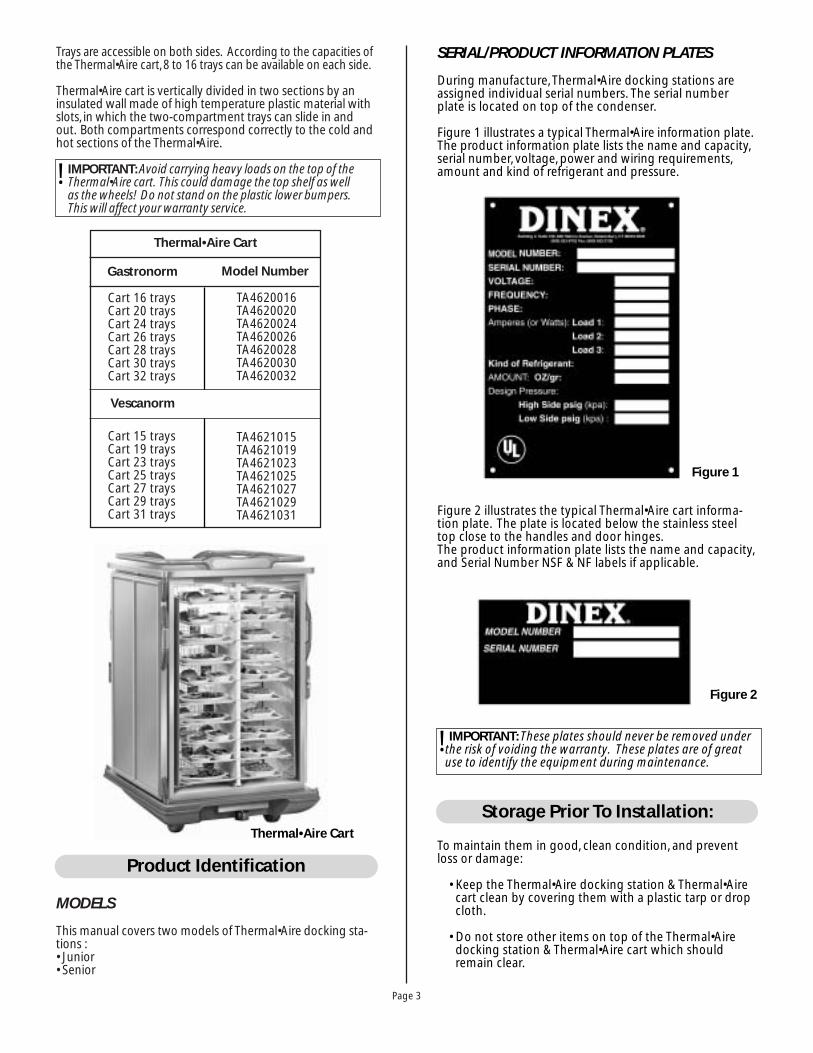
Trays are accessible on both sides. According to the capacities ofthe Thermal•Aire cart, 8 to 16 trays can be available on each side.
Thermal•Aire cart is vertically divided in two sections by aninsulated wall made of high temperature plastic material withslots, in which the two-compartment trays can slide in andout. Both compartments correspond correctly to the cold andhot sections of the Thermal•Aire.
IMPORTANT: Avoid carrying heavy loads on the top of the Thermal•Aire cart. This could damage the top shelf as well as the wheels! Do not stand on the plastic lower bumpers.This will affect your warranty service.
MODELS
This manual covers two models of Thermal•Aire docking sta-tions :• Junior• Senior
TA4620016TA4620020TA4620024TA4620026TA4620028TA4620030TA4620032
TA4621015TA4621019TA4621023TA4621025TA4621027TA4621029TA4621031
Cart 16 trays Cart 20 trays Cart 24 trays Cart 26 traysCart 28 traysCart 30 traysCart 32 trays
Gastronorm
Thermal•Aire Cart
Model Number
Cart 15 trays Cart 19 trays Cart 23 trays Cart 25 traysCart 27 traysCart 29 traysCart 31 trays
Vescanorm
Thermal•Aire Cart
SERIAL/PRODUCT INFORMATION PLATES
During manufacture, Thermal•Aire docking stations areassigned individual serial numbers. The serial numberplate is located on top of the condenser.
Figure 1 illustrates a typical Thermal•Aire information plate.The product information plate lists the name and capacity,serial number, voltage, power and wiring requirements,amount and kind of refrigerant and pressure.
Figure 2 illustrates the typical Thermal•Aire cart informa-tion plate. The plate is located below the stainless steeltop close to the handles and door hinges.The product information plate lists the name and capacity,and Serial Number NSF & NF labels if applicable.
To maintain them in good, clean condition, and preventloss or damage:
• Keep the Thermal•Aire docking station & Thermal•Airecart clean by covering them with a plastic tarp or dropcloth.
• Do not store other items on top of the Thermal•Airedocking station & Thermal•Aire cart which shouldremain clear.
Product Identification
Figure 1
Figure 2
IMPORTANT: These plates should never be removed underthe risk of voiding the warranty. These plates are of greatuse to identify the equipment during maintenance.
Storage Prior To Installation:
!
!

SEE THERMAL•AIRE™ DOCKING STATIONLOCATION SELECTION & INSTALLATIONINSTRUCTIONS MANUAL
ELECTRICAL POWER REQUIREMENTS
1. The characteristics of the electric power supply mustmatch the power requirements specified on theThermal•Aire product identification plate. The plate isplate is located on top of the condenser (Fig. 3).
WARNING: Injury and equipment damage could resultfrom improper lifting. Refer to the appropriate dimensionand check the weight of the unit being installed. Use enoughworkers with experience lifting heavy equipment to placethe Thermal•Aire on the supporting surface.
Page 4
Figure 3
ELECTRICAL & REFRIGERATION REQUIREMENTS
Thermal•Aire with compressor unit
Heat Emission• Junior: 1100 Watt/3756 BTU’s• Senior: 1300 Watt/4439 BTU’s• Average power calculated as follows: 2 hours cold cycle
followed by 45 minutes rethermalization cycle. For othercycles, please contact us.
Sound Level: 57 dba.
IMPORTANT: The Thermal•Aire docking station is equipped with two separate evaporators, each individually controlled by an electrovalve and a pressure reducing valve.
!
!
Installation:
START-UP CHECK LIST
This inspection checks for proper electrical to theThermal•Aire and verifies basic operation of the unit.
CAUTION: Equipment damage and faulty operation willresult if electrical supplies fall below requirements. This may be caused by other equipment wired on the same supplyline. During tests completion, adjustments, and ofthe Thermal•Aire unit, turn on all equipment wired onthe same supply line.
1. Refer to the installation document and verify that thespecified clearances are met.
2. Verify that the voltage supplied complies with the volt-age requirements specified on the Product identifica-tion plate, located on the right side of the top of theunit, on protective compressor cover. Verify that thesupply cables are suitable for the requirements.
3. Operate a complete cycle to check each function of theThermal•Aire unit. Temperatures of the cold and hotsections are pre-set at the factory. Both can be adjustedto meet customer's requirements. (Refer to program-ming manual)
4. Refer to chapter 3, operation.
CONNECTING THERMAL•AIRE CART TO THERMAL•AIR DOCKING STATION
Connect the Thermal•Aire cart to the Thermal•Aire dockingstation in minimum of 20 minutes prior to the beginningof the retherm cycle. To do so, please proceed as follows:
The characteristics of the electrical power supply mustmatch the power requirements specified on theThermal•Aire docking station product identification plate(Fig. 1). The plate is located on the top of the unit, on com-pressor cover. Also refer to the electrical schematics.
Refrigerant Type: R404ACharge: 27.4 OZ/700 grDesign Pressures: HP (High Side) 435 PSIG
DB (Low Side) 174 PSIG
Thermal•Aire with air compressor unit
Model Junior Senior
Supply 3Phase/60Hz 3Phase/60Hz
Power Of Heating Elements 6000 Watts 7800 Watts
Total Power
Amp (A)208V/60Hz/
3Ø
PH1
PH2
PH3
7600 Watts
24, 5A 29, 5A
24, 5A 29, 5A
16, 5A 21, 5A
9500 Watts
!
Figure 4
Operation:
Page 5
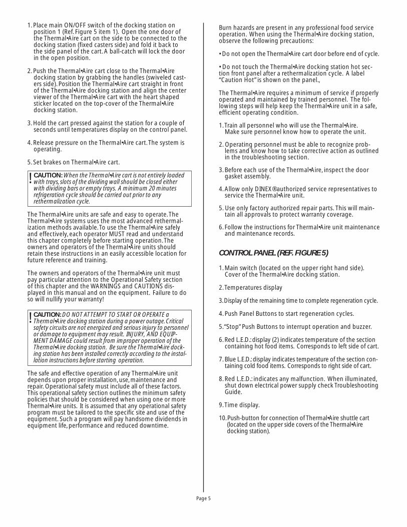
1. Place main ON/OFF switch of the docking station onposition 1 (Ref. Figure 5 item 1). Open the one door ofthe Thermal•Aire cart on the side to be connected to thedocking station (fixed casters side) and fold it back tothe side panel of the cart. A ball-catch will lock the doorin the open position.
2. Push the Thermal•Aire cart close to the Thermal•Airedocking station by grabbing the handles (swiveled cast-ers side). Position the Thermal•Aire cart straight in frontof the Thermal•Aire docking station and align the centerviewer of the Thermal•Aire cart with the heart shapedsticker located on the top-cover of the Thermal•Airedocking station.
3. Hold the cart pressed against the station for a couple ofseconds until temperatures display on the control panel.
4. Release pressure on the Thermal•Aire cart. The system isoperating.
5. Set brakes on Thermal•Aire cart.
CAUTION: When the Thermal•Aire cart is not entirely loadedwith trays, slots of the dividing wall should be closed eitherwith dividing bars or empty trays. A minimum 20 minutesrefrigeration cycle should be carried out prior to any rethermalization cycle.
The Thermal•Aire units are safe and easy to operate. TheThermal•Aire systems uses the most advanced rethermal-ization methods available. To use the Thermal•Aire safelyand effectively, each operator MUST read and understand this chapter completely before starting operation. Theowners and operators of the Thermal•Aire units shouldretain these instructions in an easily accessible location forfuture reference and training.
The owners and operators of the Thermal•Aire unit mustpay particular attention to the Operational Safety sectionof this chapter and the WARNINGS and CAUTIONS dis-played in this manual and on the equipment. Failure to doso will nullify your warranty!
CAUTION: DO NOT ATTEMPT TO START OR OPERATE aThermal•Aire docking station during a power outage. Criticalsafety circuits are not energized and serious injury to personnelor damage to equipment may result. INJURY, AND EQUIP-MENT DAMAGE could result from improper operation of theThermal•Aire docking station. Be sure the Thermal•Aire dock-ing station has been installed correctly according to the instal-lation instructions before starting operation.
The safe and effective operation of any Thermal•Aire unitdepends upon proper installation, use, maintenance andrepair. Operational safety must include all of these factors.This operational safety section outlines the minimum safetypolicies that should be considered when using one or moreThermal•Aire units. It is assumed that any operational safetyprogram must be tailored to the specific site and use of theequipment. Such a program will pay handsome dividends inequipment life, performance and reduced downtime.
!
Burn hazards are present in any professional food serviceoperation. When using the Thermal•Aire docking station,observe the following precautions:
• Do not open the Thermal•Aire cart door before end of cycle.
• Do not touch the Thermal•Aire docking station hot sec-tion front panel after a rethermalization cycle. A label“Caution Hot” is shown on the panel.,
The Thermal•Aire requires a minimum of service if properlyoperated and maintained by trained personnel. The fol-lowing steps will help keep the Thermal•Aire unit in a safe,efficient operating condition.
1. Train all personnel who will use the Thermal•Aire.Make sure personnel know how to operate the unit.
2. Operating personnel must be able to recognize prob-lems and know how to take corrective action as outlinedin the troubleshooting section.
3. Before each use of the Thermal•Aire, inspect the doorgasket assembly.
4. Allow only DINEX® authorized service representatives toservice the Thermal•Aire unit.
5. Use only factory authorized repair parts. This will main-tain all approvals to protect warranty coverage.
6. Follow the instructions for Thermal•Aire unit maintenanceand maintenance records.
CONTROL PANEL (REF. FIGURE 5)
1. Main switch (located on the upper right hand side).Cover of the Thermal•Aire docking station.
2. Temperatures display
3. Display of the remaining time to complete regeneration cycle.
4. Push Panel Buttons to start regeneration cycles.
5.“Stop” Push Buttons to interrupt operation and buzzer.
6. Red L.E.D.: display (2) indicates temperature of the sectioncontaining hot food items. Corresponds to left side of cart.
7. Blue L.E.D.: display indicates temperature of the section con-taining cold food items. Corresponds to right side of cart.
8. Red L.E.D.: indicates any malfunction. When illuminated,shut down electrical power supply check TroubleshootingGuide.
9. Time display.
10. Push-button for connection of Thermal•Aire shuttle cart(located on the upper side covers of the Thermal•Airedocking station).
!

Page 6
CAUTION: Press switches with finger tip only. Do not usekitchen utensils or anything sharp to operate switches.
MAIN SWITCH (REF. FIGURE 5, ITEM 1)
1. This main switch must be turned off “0” position after eachcycle. Should a new cycle be started, place ON/OFF switchon “1”, and connect Thermal•Aire cart.
2. Always turn off the main switch when cleaning the outsideof the station. During sanitation of the inside of the
Thermal•Aire docking station or in case of technical service,turn off main power at disconnect or breaker panel.
CAUTION: Do not attempt to start or operate a Thermal•Airedocking station during a power outage. Critical safety cir-cuits are not energized, and serious damage to equipmentmay result.
!
!
CONTROL PANEL
TO CO N N E C T
THE THERMAL•AIR CART TO THE DOCKING TERMIAL
Open the Thermal•Aire cart door (hooking side)
Switch on the Thermal•Aire docking termial
Connect the Thermal•Aire cart smoothly
Once the temperatures are displayed, lock the wheels.
Figure 6
3. At the buzzer: Press “STOP” to stop the buzzer for imme-diate stopping of buzzer signal; or automatic stop andswitch in the holding mode for the hot preparations(example: factory setting: < 194°F >) and for the coldpreparations (example: factory setting: < 32°F, 36°F >).Holding (example: factory setting: < 15 minute >). Themessage “END” is displays.
4. When ready for service, press “STOP”.
5. Release the cart breaks.
6. Press one of the two cart release buttons on the side ofthe docking station to disconnect the cart.
7. Grab the handles of the cart and roll it away from the station.
8. Place the main switch on position “0” (STOP)
9. Close the door of the Thermal•Aire cart.
10. Proceed to the distribution of the trays.
NOTE: Should the system be programmed for clock-oper-ated automatic starts of retherm cycles, the key-board islocked until the buzzer signaling the end of the cycle rings.It is not necessary to press “P1”,“P2” or “P3” to launch thecycle. Should a program be launched manually or theoperation of the equipment stopped, simultaneously press“P1” and “P3” keys, and then the required key.
IMPORTANT: The settings like duration of cycles, operatingtemperatures in hot line or in a mix of hot line and cook-chill, time setting or automatic starts are only achievedthrough the Infra-Red programming box. When needed,please refer to the manual or consult Dinex®.
AUTOMATIC MODE
NOTE: Please refer to Figure 6 for references on the displayunder control panel.
1. Display: (3) Att=/HLd= If programmed, cold forcing preparations for a preset duration in the section for the cold preparations. When in Manual, it is impossible to launch a retherm cycle.
2. Display: (2) dE= If programmed, defrost cycle isin process. Duration and frequency are pre-set : the refrigeration stops in bothsections. Only available if products are stored for more than 4 hours.
Display:(9) dIFxx=/LAtxx= Indicates how late (in Minutes.) was the cart connected for a clock-controlled automatic cycle (Max.tolerance is 1 hour).
Display:9)ALMxx= Indicates the duration of the power shortage that occurredduring the retherm cycle when between 1 and 5 minutes. If more, the rethermcycle is stopped.
MANUAL MODE
1. Upon connection of Thermal•Aire cart, the ventilationand the refrigeration starts in the both sections (exam-ple: factory setting: <0°F; 4°F>).
2. In manual mode: To begin a cycle, depress “P1”,“P2” or“P3” (example: factory setting: 266°F< 45 minute, 50minute, 55 minute >) 5minute stabilization included.
!
!
2 3
495 4 4
7 86
0 1
10 1
Figure 5
!

Page 7
Display: (2) 1-- Faulty temperature probe in hot section.
Display:(2) 2-- Faulty temperature probe in cold section.
DISTRIBUTION
During tray distribution to the patients, it is recommended toopen only one door at a time. By doing so, the Thermal•Airecart and the trays will remain at the correct temperatures for alonger period of time.
Obviously, both doors can be opened for serving whenpatients' rooms are on both sides of a corridor, or if there issufficient personnel to serve fast.
The single-tray system simplifies distribution. Just take thetray out of the Thermal•Aire cart and serve the patient.
TRAY COLLECTION
After each meal, the Thermal•Aire cart can be used to collectthe dirty trays. A plastic bag can be hung onto the side of thecart to collect all the trash and food wastes.The trays will bere-placed in their previous position, and then transported tothe washing area for sanitation.
TRANSPORT OF THE THERMAL•AIRE CART SHUTTLES IN VANS OR TRUCKS
NOTE: Please, strictly comply with following instructions.
1. The tail gate of the truck should always be level with theloading and unloading dock. If the tail gate is higherthan the dock, the casters will bump against the tailgateand this can damage both the casters and their attach-ments. (Fig. 7)
2. Once the Thermal•Aire cart is loaded inside the truck, theyshould be lined up and carefully secured to the wall of thetruck by means of straps and belt tighteners. (Fig. 8)
Loading the shuttles inside the truckAligning the tail gate or dock with the loading platform or dock.
Transport inside the truckEach shuttle should be secured to the walls by means oftransport straps.
**
43.3"110cm
Figure 7
Figure 8
Maintenance on the Thermal•Aire unit must be performedon a regular basis to keep the unit running properly.Follow the maintenance instructions in this chapter andproblems will be kept to a minimum. If problems do occur,refer to the troubleshooting chart.
CAUTION: DEATH, INJURY, OR EQUIPMENT DAMAGE mayresult from improper service or maintenance practices.Always turn the main power switch or breaker switch to OFF,on each unit before starting service, maintenance or repairs.
PREVENTIVE MAINTENANCE
1. THERMAL•AIRE CART
DailyThe Thermal•Aire cart can be hose-washed. However, we recommend not to use water pressure above 87 psi (6 bars).Higher pressure may damage the silicone rubber gaskets andother parts. Cleaning is very important, but it should not be thecause of deterioration of the equipment. Use ONLY chlorine-free, non-abrasive, fungicide, germicide detergents, and followthe manufacturers recommended instructions as indicated.
Maintenance
!!
! WARNING: Air-drying the inside and outside of theThermal•Aire cart is important after every cleaning.Air-pressure not to exceed 87 psi (6 bars) should be installed inthe vicinity of the Thermal•Aire cart washing area. A hosewith an air-spray-gun should be used to dry the Thermal•Airecart, inside and out. Pay particular attention to the air ductson each side. If no air-pressure is available, the Thermal•Airecart should be wiped out thoroughly. DO NOT tilt theThermal•Aire cart by pushing down on an open door to allowdrainage of water, this can result in damage to door pivotsand hinges and void warranty.

Page 8
Monthly/Facilities Maintenance1. Check door hinges, latches and catches. Adjust if necessary.
2. Inspect door and frame gaskets, replace if necessary.
3. Inspect vertical separation wall, and be sure wall has notbecome loose, if so tighten screws and nuts.
4. Check casters for rotation and swivel.
5. Check casters brakes mechanism for proper function.
Procedure to remove or install an Air Dam
1.This is done when cleaning the wall
2. Align the Air Dam on the 2 screws used to attach it to thecenter wall (Fig. A).
3.While pressing the Air Dam on the wall, slide it horizontallyuntil it passed the pin and you hear the locking sound (Fig. B).
IMPORTANT: The Air Dam should slide freely from bottomto top (Fig. C). The Air Dam holding screws are factoryglued, do not unscrew.
4.To remove the Air Dam, perform steps 1, 2, & 3 in reverseorder.
2. THERMAL•AIRE DOCKING STATION
Daily/Facilities Food Service PersonalWith the exterior of the Thermal•Aire docking station only.As any other piece of equipment, it should be cleaned on a
regular basis with a wet cloth or sponge. Then wipe it drywith a smooth cotton rag. "Avoid the use of abrasive prod-ucts or chlorines".
WARNING: Inside and outside front panel of the hot sectionof Thermal•Aire docking station stays hot for a short periodof time, after rethermalization, BE CAREFUL when cleaning.
Monthly/Facilities Maintenance1. Connect cart and check seal between cart and docking
station. Adjust if necessary using the leveling feet.
2. Check and adjust the two cart micro contact switches.
3. Check and tighten rear mounting bolts both upper andlower.
4. Inspect refrigeration condenser for cleanliness, clean asrequired.
5. Inspect docking station gasket for seal with cart, replaceif necessary. Damage gaskets are not covered under warranty.
Quarterly/Facilities MaintenanceInspect electrical connections (heating elements, connec-tion blocks, electronic board, linking strap, electromag-nets). To access these, disconnect electrical power toequipment and remove right side panel. Carefully removedust from electrical board using a soft brush and computertype compressed air.
!
Figure 9
!
Every 6 Months
CAUTION: Before servicing, DISCONNECT ELECTRICALPOWER TO THE EQUIPMENT.
1. Remove the left and right ABS plastic panel. Check allelectrical connections for tightness including heat ele-ments, contactors, and all other electrical connectionblocks. Also check tightness of linking strap to CPU board. Carefully remove dust by using a brush and computer type compressed air. Reinstall right and left panels.
2. Remove top access cover to refrigeration compressor(see section 4). Thoroughly clean the condenser coils.Recommend using compressed air, followed by athrough vacuuming. Reinstall top refrigeration accesscover. Remove front deflector panels. This will accessthe hot and cold side refrigeration evaporators. Cleanand reinstall deflector panels.
3. Remove front deflector panels. This will access hot andcold refrigeration evaporator coils. Clean and reinstallthe deflector panels.
NOTE: This operation may need to be performed more fre-quently depending upon facility cleanliness.
3. CLEANING OF PLASTIC PARTS & TRAYS
NOTE: It is extremely important to read the followinginstructions for cleaning plastic panels.
1. It is sufficient to wash with warm or hot water (notexceeding 60ºC/140ºF) to which has been added somediluted detergent. The detergent used must have a lowalkaline value and contain a very low percentage ofcaustic soda.
2.The detergent must not exceed the dilution rate recom-mended by the supplier.
3. Make sure that a thorough rinsing cycle follows everycleaning cycle in order to avoid any left over detergentremaining on the plastic parts (rinse water must notexceed 80ºC/180ºF).
4. Rinse water must contain the lowest percentage of non-ionic surfactants. It must not exceed the dilution rate rec-ommended by supplier. Make sure that all plastic panelsis thoroughly dry before use.
CAUTION: To avoid injury due to hot surfaces, wear insulatedgloves for handing and cleaning.
IMPORTANT: Manufacture accepts no responsibility if theabove instructions are not strictly carried out.
Page 9
Figure 11
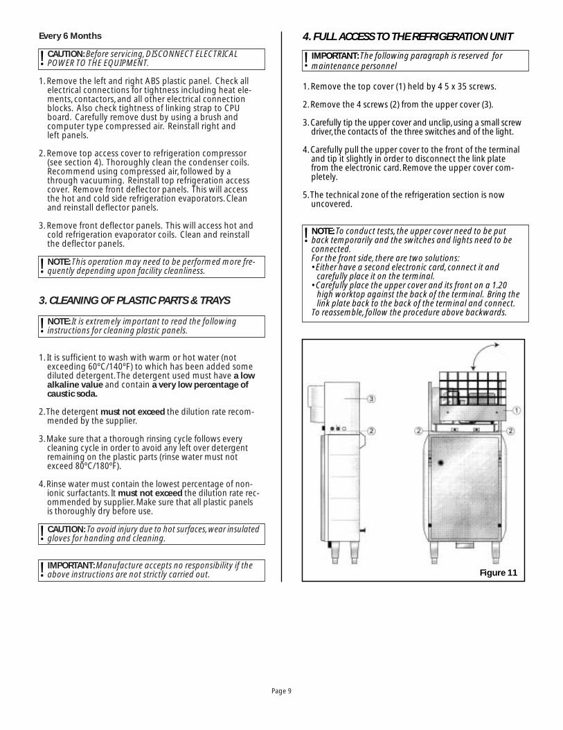
4. FULL ACCESS TO THE REFRIGERATION UNIT
IMPORTANT: The following paragraph is reserved formaintenance personnel
1. Remove the top cover (1) held by 4 5 x 35 screws.
2. Remove the 4 screws (2) from the upper cover (3).
3. Carefully tip the upper cover and unclip, using a small screwdriver, the contacts of the three switches and of the light.
4. Carefully pull the upper cover to the front of the terminaland tip it slightly in order to disconnect the link platefrom the electronic card. Remove the upper cover com-pletely.
5.The technical zone of the refrigeration section is nowuncovered.
NOTE: To conduct tests, the upper cover need to be putback temporarily and the switches and lights need to beconnected.For the front side, there are two solutions:• Either have a second electronic card, connect it and
carefully place it on the terminal.• Carefully place the upper cover and its front on a 1.20
high worktop against the back of the terminal. Bring thelink plate back to the back of the terminal and connect.
To reassemble, follow the procedure above backwards.
!
!
!
!
!
!
!

Page 10
Troubleshooting
The Power On indicatorremains off.
1. No power2. Switch set to 03. Fuses blown
4. Button defect5. Indicator defect
Electric
DisplayIndications
«Cold» systemfailure
212
22
1. Check electrical power.2. Check that the On/Off switch is set to 1.3. Check that the F1 and F2 fuses are not
blown.4. Check the B1 button.5. Check the V1indicator.
The terminal does notstart.
Cart not properlydocked.
1Check cart & docking station connections.
The cart is not locked.1. Contactor defect
2. Detectors defect
3. Thermostat defect4. Circuit breaker defect
5.Transformer defect
6. F3 fuse blown7. Electromagnets
defect
12
2
2
22
22
2
2
Place a protective plate onto the magnets1. Check that the KM2 contactor is operating
property.2. If yes, check the C1 and C2 detectors;
replace them, if necessary.Check that the KM1 contactor is operatingproperty.
3. If KM1 OFF, check the TH1 safety thermostat.4. If yes, check that the DJ1 circuit breaker
is reset.5. If yes, check that the TR1 transformer
has power.6. If yes, check the F3 fuse.7. If OK, check that the EA1 and EA2
electromagnets are correctly suppliedwith 24V.If yes, replace the electromagnets.
The lock works, but notthe display.
Alarm indicator off.
1. Power supplydefect
2. Connection defect
2
2
2 or 3
Check that the CPU board is correctly supplied with 24V between 41 and 42If yes, check that the display board/relayboard connection is correct.Check the display board, the relay boardand the wire braiding.Replace the defecting item.
The lock works, the display operates, but theterminal does not start.
Program not valid 2Check the programming.
The Defect indicator is on. Wiring/bad contactdefect
2Check on the board the safety loops from7 to 18 and 9 to 12.
The unlock does not work. 1. Button wiring defect2. Timer defect
23
1. Check the wiring of the B2, B3 buttons.2. Replace the T1 timer.
Display (2) 1-- Hot preparationsenclosure tempera-ture probe defect
2Check the probe; replace it, if necessary.Check the connections 1-2-3 on the board.Check the probe insulation with respect tothe frame.
Display (2) 2-- Cold preparationsenclosure tempera-ture probe defect
2Check the probe; replace it, if necessary.Check the connections 4-5-6 on the board.Check the probe insulation with respect tothe frame.
Display (2) HLP Bad contact on safetyloops 9 to 15 or 8 to 17
2Check the safety loops.
Micro gas leaks at threadedconnections.
N. B.: Innervation Levels1: Customer2: Customer Maintenance3: Dinex Service Agent
Leak 3Search for the leak, repair.
DESCRIPTIONFAILURETYPE REMEDY
INTERVENTIONLEVELPOSSIBLE CAUSE

Page 11
«Cold» systemfailure
The compressor does notrotate (>40° C in theenclosure).
1. Program not valid2. Power supply defect
3.Wiring defect
4. Bad pressure controller setting
5. Electrovalves defect
22
2
3
2
1. Check the programming.2. Check that the compressor is correctly
supplied with 208V Single Phase.3. Check that it is correctly wired at the
pressure controller and the black box.4. Check the pressure controller setting.
5. Check power supply to electrovalves.
Not cooling. Ventilation defect 2
2
32
If the duct is physically blocked.Remove obstruction.If the fan is electrically blocked, check thepower supply.If it is OK, replace the fan.Otherwise, check the wiring at the electricslide-in unit.
Unacceptable cold tem-peratures.
1. Trays or adapter bars missing
2. Doors not closed 3. Seal problem4. Tight protection
defect5. Program not valid6. HP/LP pressures too
low
1
112
23
1. Check that the trays and adapter bars are present.
2. Check that the doors are closed.3. Check the seals.4. Check the tight protection setting.
5. Check the programming.6. Search for the presence of leaks; repair.
Improper cooling of coldsystem on hot side.
Fans do not rotate 22
Check the power supply.Check whether the CD1 condenser isdefective.
The compressor rotatesbut the condenser fandoes not rotate.
Power supply defectFan blocked
22
3
Identify the defect:• check the fan power supply (208V)• check that it is not blocked• If everything is OK, replace the fan
«Hot» systemfailure
No start cycle. Program not valid 2Check the programming.
No ventilation on hot side. 1. Physically blocking 2. Power supply defect
22 or 3
1. Check that the fan is not physically blocked.2. Check that the KM5 has proper voltage.
If yes, replace the motors.
Ventilation OK but not hot. Power supply defect 22
Check that the KM6 has proper voltage.If yes, replace the heaters.
Improper hot systemperformances.
2Check that the ventilation is OK and that the heating system has started.
Refrigerationfailures whensetting ormaintaining atemperature
The device stops workingcompletely + remainingheating time is blocked(display 3) + red failurelight (8) on front panel ison + cold preparationtank temperature displayis blocked (display 2) atthe time of the failure +green led (7) is blinking +intermittent buzzer.
Cold temperatureexceeds 40° C formore than 5 secondswhile setting the tem-perature, during thestabilization, endbuzzer and whilemaintaining.
2 or 3Press the STOP key to stop the buzzer +delete the remaining heating time. Reset byswitching off the mains.Carry out all checks mentioned in the“REFRIGERATION FAILURES paragraph.
DESCRIPTIONFAILURETYPE REMEDY
INTERVENTIONLEVELPOSSIBLE CAUSE
N. B.: Innervation Levels1: Customer2: Customer Maintenance3: Dinex Service Agent

Page 12
REP
LAC
EMEN
T PA
RTS
Ther
mal
•Air
e D
ock
ing
Sta
tio
n &
Car
t
Page 13
REP
LAC
EMEN
T PA
RTS
Ther
mal
•Air
e D
ock
ing
Sta
tio
n

Page 14
Rep
lace
men
t P
arts
Ther
mal
•Air
e D
ock
ing
Sta
tio
n

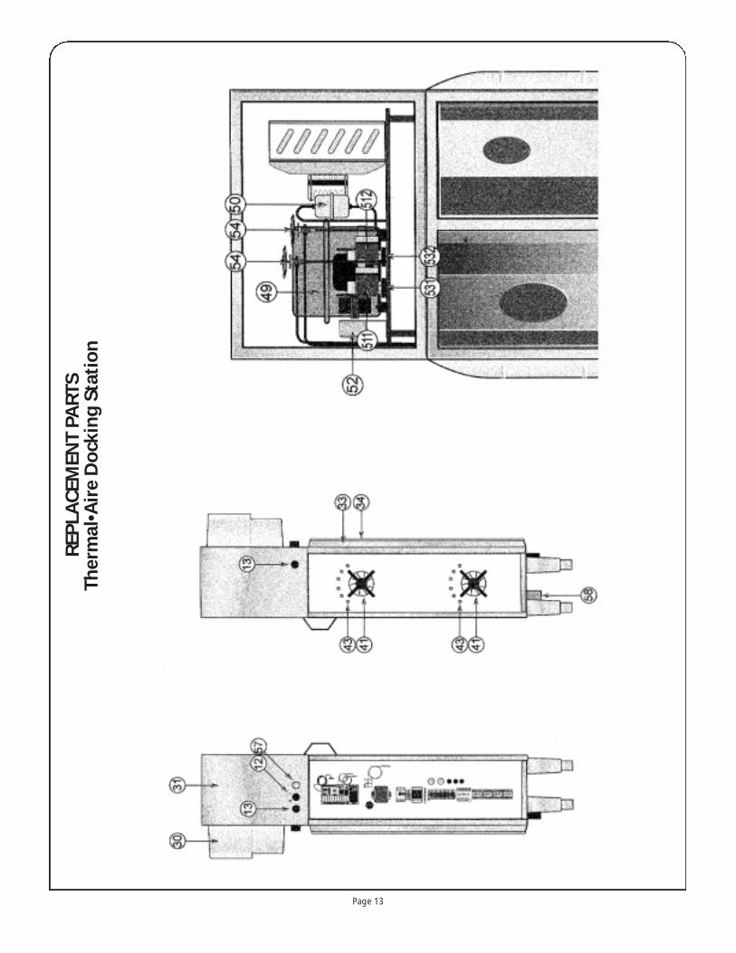
56 3000 19 65 Feet, stainless steel57 1462 56 00 Light, on-line58 1443 00 02 Evaporator, water condensate 160W 120V60 1746 27 00 Rack, side assembly, 20 cap gastro
1746 27 02 Rack, side assembly, 24 cap gastro1746 27 10 Rack, side assembly, 26 cap gastro1746 27 04 Rack, side assembly, 30 cap gastro
60 1746 27 01 Rack, side assembly, 19 cap comfort1746 27 03 Rack, side assembly, 23 cap comfort1746 27 11 Rack, side assembly, 25 cap comfort1746 27 05 Rack, side assembly, 29 cap comfort
61 3746 21 03 Door assembled 20/233746 21 04 Door assembled 30/31
62 5000 22 19 Side panel, cart, S/S - junior5000 22 21 Side panel, cart, S/S - senior
63 3746 21 05 Top assembled 64 1307 01 88 Gasket frame 20/23
1307 01 89 Gasket frame 30/3165 1746 28 22 Rail, separation 67 3000 64 63 Middle wall Air Dam, 20 gastro
3000 64 64 Middle wall Air Dam, 24 gastro3000 64 65 Middle wall Air Dam, 26 gastro3000 64 66 Middle wall Air Dam, 30 gastro3000 64 67 Middle wall Air Dam, 19 comfort3000 64 68 Middle wall Air Dam, 23 comfort3000 64 69 Middle wall Air Dam, 25 comfort3000 64 70 Middle wall Air Dam, 29 comfort
671 6000 63 15 Injected Air Dam gastro 671 6000 63 17 Injected Air Dam comfort 672 6000 27 61 Manufactured Air Dam gastro 672 6000 63 16 Manufactured Air Dam comfort68 6000 72 20 Bumper, lower 69 6000 42 11 Door hinge 2370 6000 68 68 Cap, door hinge & handle71 1745 08 10 Roller, center 72 3746 21 06 Bracket, center roller73 1344 01 17 Nozzle, bronze PA cart, C10X13X16 74 1312 09 08 Latch, cart, no key75 1312 09 10 Catch, door latch, PA cart76 6000 42 10 Bracket, grey, door catch77 1305 00 42 Cap, blue bracket78 6000 42 09 Handle, grey79 1374 16 07 Caster, S/S swivel with brakes80 5000 22 49 Caster, S/S, rigid82 1746 26 33 Top rail, S/S tubing83 6000 63 15 Bar, Air Dam, gastro, injected
6000 63 17 Bar, Air Dam, comfort, injected6000 27 16 Bar, Air Dam, gastro, manufactured6000 63 16 Bar, Air Dam, gastro, manufactured
84 1492 00 05 Plate, electromagnet85 6000 42 08 Cart top, support bracket - grey
0451 40 00 Divider bar
Page 15
Reference Number Description
1 5000 27 85 Alimentation contactor LC1D25004P7/230V (KM1)
2 1472 24 11 Transformer 208V/24V (TR1)3 1424 50 04 Fuse, 4 Amp (F3)4 1422 80 30 Contactor ,9A, 24V 50/60Hz Coil
(KM6)5 1422 40 02 Circuit Breaker 6-10 Amp (DJ1)6 1421 24 11 Contactor ,9A, 24V 50/60Hz Coil
(KM4)7 1421 24 11 Contactor ,9A, 24V 50/60Hz Coil
(KM5)8 1421 24 11 Contactor ,9A, 24V 50/60Hz Coil
(KM3)9 1453 01 03 Thermostat, safety 180 to 220°C (TH1)
10 1464 04 00 Buzzer, 2900 Hz, 85 DB, 24V (BZ1)11 5000 25 07 Millennium Logic Controller 11 3000 65 23 Millennium Logic Controller
(Shabbat Type Optional)12 1462 50 00 Switch, ON/OFF13 1462 52 03 Head, green push switch
1462 51 03 Body, green push switch14 1424 50 04 Fuse, 4 Amp (F1, F2 & F3)15 1424 50 04 Fuse, 4 Amp (F1, F2 & F3)16 1789 10 21 Card, Electronic, Display Board17 1789 10 12 Linking strap, linking CPU to IR18 1789 10 22 Card, relay (IR) (CE1)19 1454 01 03 Probe, Type 1K28053, 2m, 8” long20 1424 50 04 Fuse, 4 Amp (F1, F2 & F3)21 6000 18 34 Capacitor 18 UF (CD1)22 6000 18 33 Capacitor 18 UF (CD7)23 1453 01 00 Thermostat, Safety 50/250 C (TH2)24 5000 62 35 Relay KM7 (Shabbat Type Optional)30 6000 65 76 Panel, front junior & senior31 3000 46 11 Top cover - stainless steel32 6000 65 93 Panel Side - junior
6000 65 94 Panel Side - senior33 1746 16 00 Frame, aluminum assembled - junior
1746 16 01 Frame, aluminum assembled - senior34 1307 01 90 Gasket, frame - junior
1307 01 91 Gasket, frame - senior35 5000 07 93 Panel, front protection, cold side - junior
5000 07 94 Panel, front protection, cold side - senior36 3746 11 06 Panel, front protection, hot side - junior
3746 11 07 Panel, front protection, hot side - senior37 1746 16 03 Bracket, electromagnet-top38 3746 11 16 Guide, center roller guide39 1492 00 04 Electromagnet40 1428 00 82 Detector, cart proximity41 1431 42 13 Motor, hot side, 208/230V42 1431 42 17 Motor, cold side43 1441 05 95 Elements, heating 208V 3000W
1441 05 96 Elements, heating 3900W208V - senior46 6000 51 08 Control panel47 1746 19 01 Evaporator, hot side - junior
1746 19 02 Evaporator, hot side - senior48 1746 19 03 Evaporator, cold side - junior
1746 19 04 Evaporator, cold side - senior49 1744 89 06 Compressor, air cooled, R404A50 1362 01 43 Filter Dryer511 3000 16 10 Coil, refrigeration (EV1 & EV2)512 3000 16 10 Coil, refrigeration (EV1 & EV2)52 1362 02 56 Pressure control, refrigeration531 1362 01 27 Electrovalve, Refrigeration Flow (EV1& EV2)532 1362 01 27 Electrovalve, Refrigeration Flow (EV1& EV2)54 1362 02 40 Valve, pressure reducer, TS2
1362 01 19 Reducer, pressure nozzle, hot side
Reference Number Description
Parts Chart Parts Chart
NOTE: Please contact your nearest distributor to get thename of your Authorized Service Agency in your area, orfor replacement parts and information regarding theproper maintenance and repair of Dinex equipment.In order to maintain the various compliances and safetycertifications, only factory-supplied replacement partsshould be used. The use of other than factory-suppliedreplacement parts will VOID THE WARRANTY.
!

Page 16
SPARE PARTSThermal•Aire Hitching Option
Reference Number Description QT
1 1224 07 50 Hinge Pin 1
2 6000 41 64 Roller 1
3 SPL10063 Circlips 1
4 3000 47 69 Drawbar 1
5 1348 04 01 Lg Spring 100mm 1
6 1348 01 01 Lg Spring 50mm 1
7 16000 47 54 Plot Amortisseur 1
8 3000 41 88 Corps d’ Attelage 1
9 3000 41 96 Unlocking Hook 1
10 SCRE0307 H M6X75 Screw 1
11 NUTS0031 H M8 Nylstop Nut 4

Page 17
ELECTRICAL DIAGRAMS

Page 18
ELECTRICAL DIAGRAMS

Page 19
WIRING DIAGRAM
208V
/3P
H/N
/T/5
0HZ
21
43
13
57
24
68
PE
P1
P2
P3
N
13
5
24
6
12
33
4
DO
UB
LE-F
LOW
JU
NIO
R =
100
0WD
OU
BLE
-FLO
W S
EN
IOR
= 1
300W
1314
A1
A2
A1
A2
12
21
BR
BE
BE
BR
km1
km6
km2
R1
KM
1
B1
TH
1 (1
80 )
F1
(4A
)
F2
R2
R3
R4
R5
R6
C1
C2
KM
2
R7
V1
12
34
56
78
910
1112
1314
1516
1718
1920
A B C D E F G H I J K L M N1
23
45
67
89
1011
1213
1415
1617
1819
20
A B C D E F G H I J K L M N
VERSION "GROUP A AIR"THERMAL•AIRE JUNIOR/SENIOR
(208V/3PH/N/T/50HZ)

43
13
24
89
13
24
13
24
1314
15
711
12
6
3 4
3 4
A1
Y1
A2
15
1618
A B
BE
BL
BR
BE
BL
BR
BE
BE
BE
BL
BL
BL
BR
BR
BR
TH
ER
MA
L•A
IRE
SE
NIO
R
TH
ER
MA
L•A
IRE
JU
NIO
R:
21
5 6
1 2
10
km3
km5
km4
DJ1
8A
M1
M2
M3
B2
B3
M4
M5
GF
1
M6
CD
2 (4
uF)
CD
3 (4
uF)
CD
4 (1
,5uF
)C
D5
(1,5
uF)
CD
6 (1
,5uF
)
CD
1 (1
8uF
)
T1
CD
7 (8
uF)
PS
1
12
34
56
78
910
1112
1314
1516
1718
1920
A B C D E F G H I J K L M N1
23
45
67
89
1011
1213
1415
1617
1819
20
A B C D E F G H I J K L M N
VERSION "GROUP A AIR"THERMAL•AIRE JUNIOR/SENIOR
(208V/3PH/N/T/50HZ)
Page 20
WIRING DIAGRAM

Page 21
BL:
BLA
CK
, WH
:WH
ITE
, BE
:BLU
E, R
E:R
ED
, YE
:YE
LLO
WG
R:G
RE
EN
, BR
:BR
OW
N, O
R:O
RA
NG
E, P
U:P
UR
PLE
3 4
P S
1 2
34
A1
A2
A1
A2
top
cove
r
4 5
A1
A2
A1
A2
56
56
km5
km3
km4
EV
1
- +S
ON
DE
2
- +S
ON
DE
1
BZ
1
400
0
24V23
0
0
TR
1 10
0VA
F3
(4A
)
KM
6
KM
4
42 41 40 39 38 37 361 2 3
IR
35
4 5 6 7 8 9 10 11 12 13 14 15
2324252627282930313233 202122
16 17 18
34
CE
1
RC
1
EA
1E
A2
KM
3
EV
2
KM
5
12
34
56
78
910
1112
1314
1516
1718
1920
A B C D E F G H I J K L M N1
23
45
67
89
1011
1213
1415
1617
1819
20
A B C D E F G H I J K L M N
VERSION "GROUP A AIR"THERMAL•AIRE JUNIOR/SENIOR
(208V/3PH/N/T/50HZ)
WIRING DIAGRAM
Page 22
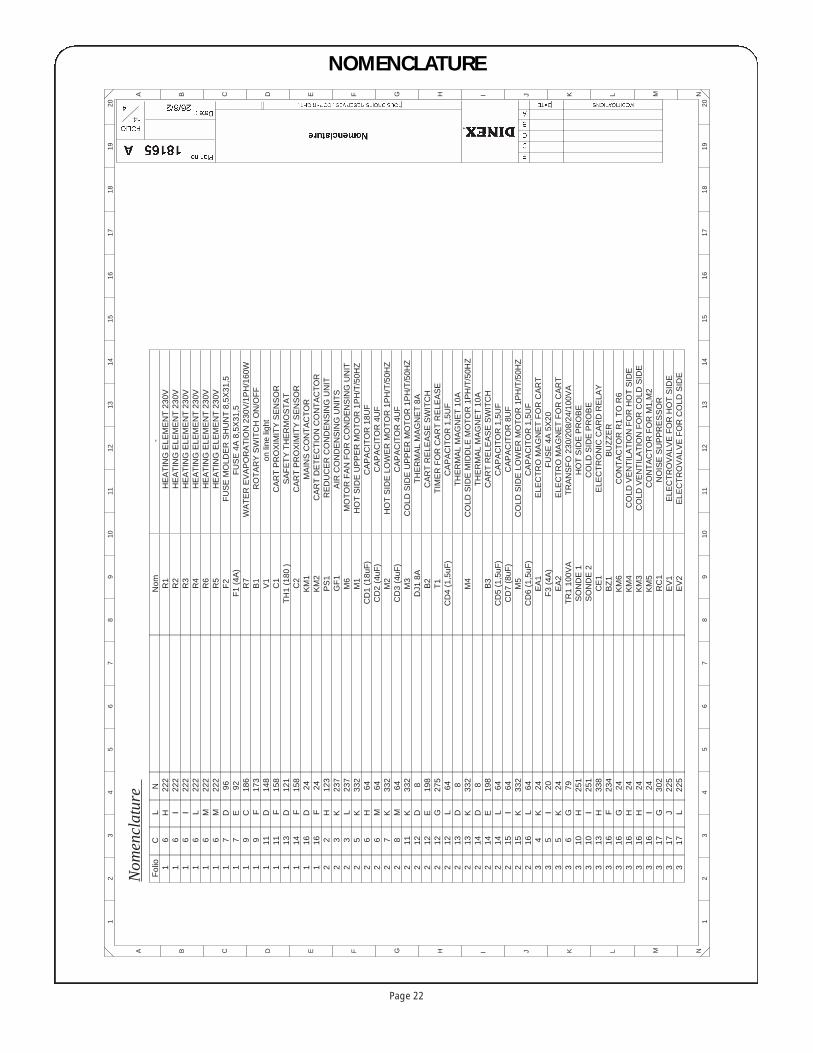
Nom
encl
atur
eF
olio
1 1 1 1 1 1 1 1 1 1 1 1 1 1 1 1 2 2 2 2 2 2 2 2 2 2 2 2 2 2 2 2 2 2 2 2 2 3 3 3 3 3 3 3 3 3 3 3 3 3 3 3
C 6 6 6 6 6 6 7 7 9 9 11 11 13 14 16 16 2 3 3 5 6 6 7 8 11 12 12 12 12 13 13 14 14 14 15 15 16 4 5 5 6 10 10 13 16 16 16 16 16 17 17 17
L H I I L M M D E C F D F D F D F H K L K H M K M K D E G L D K D E L I K L K I K G H I H F G H H I G J L
N
222
222
222
222
222
222
96 92 186
173
148
158
121
158
24 24 123
237
237
332
64 64 332
64 332 8 198
275
64 8 332 8 198
64 64 332
64 24 20 24 79 251
251
338
234
24 24 24 24 302
225
225
Nom R1
R2
R3
R4
R6
R5
F2
F1
(4A
)R
7B
1V
1C
1T
H1
(180
)C
2K
M1
KM
2P
S1
GF
1M
6M
1C
D1
(18u
F)
CD
2 (4
uF)
M2
CD
3 (4
uF)
M3
DJ1
8A
B2
T1
CD
4 (1
,5uF
)
M4
B3
CD
5 (1
,5uF
)C
D7
(8uF
)M
5C
D6
(1,5
uF)
EA
1F
3 (4
A)
EA
2T
R1
100V
AS
ON
DE
1S
ON
DE
2C
E1
BZ
1K
M6
KM
4K
M3
KM
5R
C1
EV
1E
V2
-H
EA
TIN
G E
LEM
EN
T 2
30V
HE
AT
ING
ELE
ME
NT
230
VH
EA
TIN
G E
LEM
EN
T 2
30V
HE
AT
ING
ELE
ME
NT
230
VH
EA
TIN
G E
LEM
EN
T 2
30V
HE
AT
ING
ELE
ME
NT
230
VF
US
E M
OLD
ER
SH
UN
T 8
,5X
31,5
FU
SE
4A
8,5
X31
,5W
AT
ER
EV
AP
OR
AT
ION
230
V/1
PH
/160
WR
OT
AR
Y S
WIT
CH
ON
/OF
Fon
line
ligh
tC
AR
T P
RO
XIM
ITY
SE
NS
OR
SA
FE
TY
TH
ER
MO
ST
AT
CA
RT
PR
OX
IMIT
Y S
EN
SO
RM
AIN
S C
ON
TA
CT
OR
CA
RT
DE
TE
CT
ION
CO
NT
AC
TO
RR
ED
UC
ER
CO
ND
EN
SIN
G U
NIT
AIR
CO
ND
EN
SIN
G U
NIT
SM
OT
OR
FA
N F
OR
CO
ND
EN
SIN
G U
NIT
HO
T S
IDE
UP
PE
R M
OT
OR
1P
H/T
/50H
ZC
AP
AC
ITO
R 1
8UF
CA
PA
CIT
OR
4U
FH
OT
SID
E L
OW
ER
MO
TO
R 1
PH
/T/5
0HZ
CA
PA
CIT
OR
4U
FC
OLD
SID
E U
PP
ER
MO
TO
R 1
PH
/T/5
0HZ
TH
ER
MA
L M
AG
NE
T 8
AC
AR
T R
ELE
AS
E S
WIT
CH
TIM
ER
FO
R C
AR
T R
ELE
AS
EC
AP
AC
ITO
R 1
,5U
FT
HE
RM
AL
MA
GN
ET
10A
CO
LD S
IDE
MID
DLE
MO
TO
R 1
PH
/T/5
0HZ
TH
ER
MA
L M
AG
NE
T 1
0AC
AR
T R
ELE
AS
E S
WIT
CH
CA
PA
CIT
OR
1,5
UF
CA
PA
CIT
OR
8U
FC
OLD
SID
E L
OW
ER
MO
TO
R 1
PH
/T/5
0HZ
CA
PA
CIT
OR
1,5
UF
ELE
CT
RO
MA
GN
ET
FO
R C
AR
TF
US
E 4
A 5
X20
ELE
CT
RO
MA
GN
ET
FO
R C
AR
TT
RA
NS
FO
230
/208
/24/
100V
AH
OT
SID
E P
RO
BE
CO
LD S
IDE
PR
OB
EE
LEC
TR
ON
IC C
AR
D R
ELA
YB
UZ
ZE
RC
ON
TA
CT
OR
R1
TO
R6
CO
LD V
EN
TIL
AT
ION
FO
R H
OT
SID
EC
OLD
VE
NT
ILA
TIO
N F
OR
CO
LD S
IDE
CO
NT
AC
TO
R F
OR
M1,
M2
NO
ISE
SU
PP
RE
SS
OR
ELE
CT
RO
VA
LVE
FO
R H
OT
SID
EE
LEC
TR
OV
ALV
E F
OR
CO
LD S
IDE
12
34
56
78
910
1112
1314
1516
1718
1920
A B C D E F G H I J K L M N1
23
45
67
89
1011
1213
1415
1617
1819
20
A B C D E F G H I J K L M N
NOMENCLATURE

Des
crip
tion
Tray
Cap
acity
AB
B1
H*
aa1
a2b
pH
eigh
t
Ther
mal
•Aire
Car
t Jun
ior ”
Plu
s”20
GN
or 1
9 V
N
0462
31”
36”
48”
50.5
”27
”•
•29
”3.
5”5”
Ther
mal
•Aire
Car
t Jun
ior ”
Plu
s”24
GN
or 2
3 V
N
31”
36”
48”
50.5
”27
”•
•29
”3”
5”Th
erm
al•A
ire C
art J
unio
r ”P
lus”
30 G
N o
r 29
VN
31
”36
”48
”59
.6”
27”
••
29”
3”6”
Ther
mal
•Aire
Doc
king
Sta
tion
Juni
or “P
lus”
•31
”19
”69
”•
••
••
6.6”
Ther
mal
•Aire
Doc
king
Sta
tion
Sen
ior “
Plu
s”04
6119
”78
”•
••
••
7.5
Tray
Gas
trono
rm:
21”
12.7
”•
0.5”
heig
ht•
8”9”
11.4
”•
Tray
Ves
cano
rm:
21”
14.5
”•
0.5”
heig
ht•
8.5”
10”
13.5
”•
H*:
For
shut
tle, h
eigh
t of t
op g
alle
ry=
2.75
”.C
olor
of t
rays
:ple
ase
cont
act u
s.O
ptio
n 2
cast
ers
with
bra
kes:
H+1
.5”.
Page 23
OVERALL DIMENSIONS AND REFERENCE

Page 24
DINEx INTERNATIONAL, INC. 628-2 HEBRON AVENUE, GLASTONBURY CT 06033 • 1.800.523.9752
WWW.DINEx.COM
DINEX Warranty
These Warranties cover the following Dinex International, Inc. (“Dinex”)equipment products (the “Warranted Products”):
• Rethermalization Equipment Products• Induction Heating System Products (excluding Induction Basescovered under separate warranty)
• Milk Cooler Products• Ice Cream Freezer Products• Air Curtain Refrigerator Products• Blast Chiller Products• Hot/Cold Food Counter Products• Plate, Rack and Tray Dispenser Products• Plate Heater Products• Base Heater Products• Drying and Storage Rack Products• Starter Station Products• Conveyer Products• Tray and Other Cart Products
Warranted Products also includes any other Equipment System Productsidentified on Dinex’s website (www.dinex.com) from time to time.
Standard Warranty. Except as indicated otherwise below, Dinex war-rants that the Warranted Products will be free from defects in title,material and workmanship under normal use and service and will per-form substantially in accordance with Dinex’s written technical specifi-cations for the Warranted Products (as such specifications exist on thedate the Warranted Products are shipped) (the “Product Specifications”).This warranty covers both parts and labor and is available only to end-users (the “Customers”) that purchase the Warranted Products fromDinex or its authorized distributors. For the purpose of these warranties,a defect is determined by Dinex after its good faith investigation.
Dinex Software. In addition to the other warranties set forth herein,with respect to Dinex’s licensed software, Dinex warrants that it has theright to license or sublicense the software to Customer for the purposesand subject to the terms and conditions set forth in Dinex’s standardterms and conditions.
Supplies and Accessories. Dinex’s warranty for its supplies and acces-sories that are shipped with Warranted Products is covered by a sepa-rate warranty statement, which is available at www.dinex.com.
Services. Dinex warrants that any service it provides to Customer willbe performed by trained individuals in a workmanlike manner.
DURATIONDinex provides a one year warranty for the Warranted Products.The war-ranty period begins on the date the Warranted Products are shipped toCustomer.The warranty period for any Warranted Product or part fur-nished to correct a warranty failure will be the unexpired term of thewarranty applicable to the repaired or replaced Warranted Product.
REMEDIESIf Customer promptly notifies Dinex of Customer’s warranty claim andmakes the Warranted Product available for service, Dinex will, at itsoption, either repair or replace (with new or exchange replacementparts) the non-conforming Warranted Product or parts of theWarranted Product.With respect to Dinex’s licensed software, Dinexwill, at its option, either correct the non-conformity or replace theapplicable licensed software.Warranty service will be performed with-out charge from 8:00 a.m. to 5:00 p.m. EST, Monday-Friday, excludingDinex holidays, and outside those hours at Dinex’s then prevailing serv-ice rates and subject to the availability of personnel.With respect toDinex’s warranty for the services it provides to Customer, Customer’s
® exclusive remedy shall be the re-performance of the services by Dinex.The foregoing remedies are Customer’s exclusive remedies and Dinex’s sole liability for warranty claims under this warranty statement.Thisexclusive remedy shall not have failed of its essential purpose (as thatterm is used in the Uniform Commercial Code) as long as Dinexremains willing to repair or replace defective Warranted Products with-in a commercially reasonable time after being notified of Customer’swarranty claim.
LIMITATIONSTHESE WARRANTIES ARE EXCLUSIVE AND IN LIEU OF ALL OTHER WAR-RANTIES,WHETHER WRITTEN, ORAL, EXPRESSED, IMPLIED OR STATUTO-RY. EXCEPT AS PROVIDED HEREIN, NO EXPRESS OR IMPLIED WAR-RANTIES, INCLUDING BUT NOT LIMITED TO IMPLIED WARRANTIES OFMERCHANTABILITY, FITNESS FOR A PARTICULAR PURPOSE, QUIETENJOYMENT, SYSTEM INTEGRATION AND DATA ACCURACY,WILLAPPLY.THERE ARE NO WARRANTIES THAT EXTEND BEYOND THOSEDESCRIBED IN THIS DOCUMENT AND NO PRIOR STATEMENTS BY ANYOF DINEX’S REPRESENTATIVES SHALL MODIFY OR EXPAND THESEWARRANTIES. DINEX AND DINEX’S AFFILIATES AND REPRESENTATIVESSHALL HAVE NO LIABILITY TO CUSTOMER FOR (1) ANY SPECIAL, PUNI-TIVE, INCIDENTAL, INDIRECT OR CONSEQUENTIAL DAMAGES ARISINGOUT OF OR IN CONNECTION WITH THE WARRANTED PRODUCTS,REGARDLESS OF WHETHER SUCH LIABILITY SHALL BE CLAIMED INCONTRACT,TORT, EQUITY OR OTHERWISE, (2) ANY ASSISTANCE NOTREQUIRED UNDER DINEX’S QUOTATION OR (3) ANYTHING OCCURRINGAFTER THE WARRANTY PERIOD ENDS.
DINEX’S STANDARD WARRANTIES ONLY APPLY TO END-USER-PUR-CHASERS LOCATED IN THE UNITED STATES AND CANADA. ANY SALE TOEND-USER-PURCHASERS OUTSIDE THE UNITED STATES AND CANADAWILL BE SUBJECT TO COMMERCIAL TERMS SPECIFICALLY AGREED BYDINEX AND THE END-USER PURCHASER. DINEX MAKES NO WARRANTY,EXPRESS OR IMPLIED,TO END-USER-PURCHASERS OUTSIDE THE UNITEDSTATES OR CANADA UNLESS OTHERWISE EXPRESSLY AGREED IN WRITING.
These warranties do not apply to, and Dinex shall not have any obliga-tion to Customer hereunder with respect to, any warranty claim result-ing from or arising out of: (i) normal wear and tear; (ii) damage causedby shipping or accident; (iii) damage caused by improper installation,repair or alteration not performed by Dinex; (iv) the use of theWarranted Product in combination with any software, tools, hardware,equipment, supplies, accessories or any other materials or services, notfurnished by Dinex or recommended in writing by Dinex; (v) the use ofthe Warranted Product in a manner or environment, or for any pur-pose, for which Dinex did not design or license it, or inconsistent withDinex’s recommendations or instructions on use including, but not lim-ited to, power supply requirements identified in Product Specifications;(vi) any alteration, modification or enhancement of the WarrantedProduct by Customer or any third party not authorized or approved inwriting by Dinex; (vii) Warranted Product manufactured to meet cus-tomer specifications or designs; or (viii) any accessories or supplies orother equipment or products that may be delivered with theWarranted Product.
In addition, these warranties do not cover: (i) Any defect or deficiency(including failure to conform to Product Specifications) that results, inwhole or in part, from any improper storage or handling, failure tomaintain the Warranted Products in the manner described in anyapplicable instructions or specifications, inadequate back-up or virusprotection or any cause external to the Warranted Products or beyondDinex’s reasonable control, including, but not limited to, power failureand failure to keep Customer’s site clean and free of dust, sand andother particles or debris; (ii) the payment or reimbursement of anyfacility costs arising from repair or replacement of the WarrantedProducts; (iii) any adjustment, such as alignment, calibration, or othernormal preventative maintenance required of Customer; and (iv)expendable supply items.