Math Section By: JingJing Zhu and Claire Zurn. Math Section By: JingJing Zhu and Claire Zurn.

1-800-872-7277 · www.zurn.comPage 1
Thermal Track® Design and Application Guide
THERMAL TRACK®
Design and Application Guide
CONTENTSThermal Track – How It Works . . . . . . . . . . . . . . . . . . . . . . . . . . . . . . .2Thermal Track Warmcoat™ . . . . . . . . . . . . . . . . . . . . . . . . . . . . . . . . . .2Advantages of Thermal Track . . . . . . . . . . . . . . . . . . . . . . . . . . . . . . . . .3Chart C1 – Steady State Performance of Thermal Track . . . . . . . . . . . .4Average Water Temperatures . . . . . . . . . . . . . . . . . . . . . . . . . . . . . . . . .4Steady State Performance . . . . . . . . . . . . . . . . . . . . . . . . . . . . . . . . . . . .4Heat Loss . . . . . . . . . . . . . . . . . . . . . . . . . . . . . . . . . . . . . . . . . . . . . . . .4R-Value of Floor Assemblies . . . . . . . . . . . . . . . . . . . . . . . . . . . . . . . . . .5Components . . . . . . . . . . . . . . . . . . . . . . . . . . . . . . . . . . . . . . . . . . . . .5Thermal Track Product Handling Information . . . . . . . . . . . . . . . . . . .6Thermal Track Storage . . . . . . . . . . . . . . . . . . . . . . . . . . . . . . . . . . . . . .6Estimating the Required Number of Thermal Track Panels . . . . . . . . . .6Tubing . . . . . . . . . . . . . . . . . . . . . . . . . . . . . . . . . . . . . . . . . . . . . . . . . .6Chart C2 – 3/8" Zurn PEX Flow Data . . . . . . . . . . . . . . . . . . . . . . . . .7Spacing of Panels . . . . . . . . . . . . . . . . . . . . . . . . . . . . . . . . . . . . . . . . . .7Overview of Floor Surface Requirements . . . . . . . . . . . . . . . . . . . . . . . .7Equipment Required for Installation . . . . . . . . . . . . . . . . . . . . . . . . . . .8Layout and Installation . . . . . . . . . . . . . . . . . . . . . . . . . . . . . . . . . . . . .9Detail Showing Spacing Between Panels . . . . . . . . . . . . . . . . . . . . . . .10Additional Application Guidelines . . . . . . . . . . . . . . . . . . . . . . . . . . . .11Gluing and Screwing Patterns . . . . . . . . . . . . . . . . . . . . . . . . . . . . . . .12Alternative to Gluing and Screwing . . . . . . . . . . . . . . . . . . . . . . . . . . .12Connections at Manifold . . . . . . . . . . . . . . . . . . . . . . . . . . . . . . . . . . .13Note on Caulking Grooves . . . . . . . . . . . . . . . . . . . . . . . . . . . . . . . . . .13Application – Carpet Over Subfloor . . . . . . . . . . . . . . . . . . . . . . . . . .13Application – Laminate or Vinyl Over Subfloor . . . . . . . . . . . . . . . . . .14Application Options – Wood Floors Over Thermal Track . . . . . . . . . .16Application – Hardwoods Over Subfloor . . . . . . . . . . . . . . . . . . . . . . .17Considerations with Traditional Wood FlooringOver Thermal Track . . . . . . . . . . . . . . . . . . . . . . . . . . . . . . . . . . . . . . .19Application – Tile or Stone Over Subfloor . . . . . . . . . . . . . . . . . . . . . .20Tile and Stone: More Details . . . . . . . . . . . . . . . . . . . . . . . . . . . . . . . .21Application – Over Slab . . . . . . . . . . . . . . . . . . . . . . . . . . . . . . . . . . . .22Application – Wall or Ceiling . . . . . . . . . . . . . . . . . . . . . . . . . . . . . . .24Cautions and Limitations of Use . . . . . . . . . . . . . . . . . . . . . . . . . . . . .25Typical R-values of flooring goods & materials (Appendix A) . . . . . . .26

1-800-872-7277 · www.zurn.comPage 2
Thermal Track® Design and Application Guide
THERMAL TRACK – HOW IT WORKSThermal Track panels are typically glued and screwed or stapled to a woodsubfloor. Then Zurn PEX pipe, which will carry warm water, is snappedinto the groove. Heat is trans ferred from the pipe to the aluminum andthe panel. Thermal Tracks are man u fac tured from MDF (me di um den si ty fiber board), or dense OSB (oriented strand board) which are rel a tive ly con duc tive wood products weighing 44-50 lbs. per cubic foot.The panel is grooved and then lam i nat ed with a top layer of highly con duc tive alu mi num to ef fi cient ly dis perse and trans fer heat away fromthe groove to the surface area of the whole board.
Acceleration is a measure of how fast a radiant heating sys tems responds.Aluminum is ap prox i mate ly 1000 times more con duc tive than wood.The layer of aluminum on Thermal Track and in the groove, significantlyen hanc es the trans fer of heat and even ness of heat dis tri bu tion of thepanel. See Figure A-2 to see how the heat transfers through ThermalTrack. The thin profile and relatively high den si ty con trib utes to thesuperior acceleration and deceleration of Thermal Track.Traditional radiant heating systems in concrete work well but they mustfirst charge a large ther mal mass before heat will begin coming out of thepanel. They accelerate and decelerate very slowly due to the large thermalmass and they can be hard to control. Thermal Track, being thin but rel a tive ly dense and aided by it’s con duc tive aluminum layer respondsvery rap id ly. This results in greatly improved response time with almostno overheating since there is almost no “ther mal lag” to overcome.Thermal Track can be controlled with stan dard set back thermostats.
THERMAL TRACK WARMCOAT™
The Thermal Track Warmcoat aluminum top layer provides multiplebenefits. It is highly conductive. The Warmcoat aluminum layer is alsomois ture resistant. Thermal Track is man u fac tured to meet the less than0.3 ppm form al de hyde Fed er al Hous ing Au thor i ty (FHA) stan dards. In de pen dent lab o ra to ry tests with 144°F wa ter in di cate, that due to thealu mi num Warmcoat layer, Thermal Track has virtually no de tect ablelevels of outgassing.
Figure A-1 A cross section, showing Zurn PEX pipe in groove and panel with alu mi num top layer.
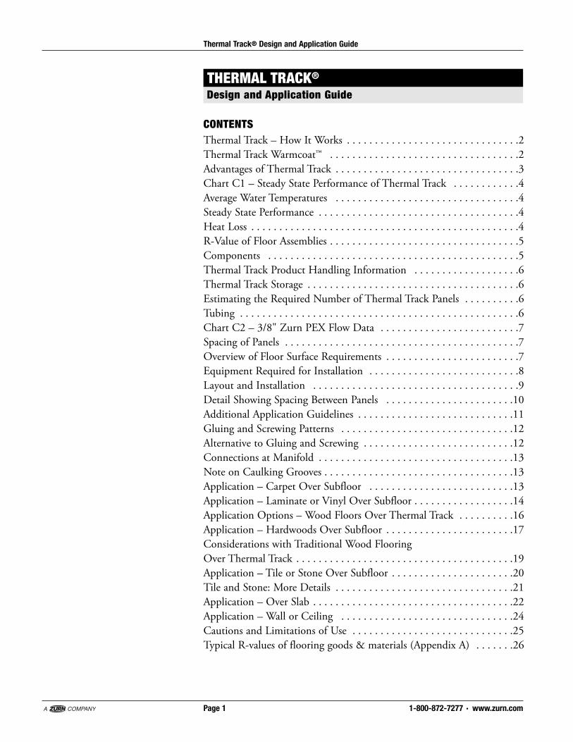
THE ADVANTAGES OF THERMAL TRACKHydronic radiant heating is the most comfortable and efficient way toheat your home or building with numerous construction benefits andunsurpassed flexibility in zoning. For many years, typical ap pli ca tions forradiant systems involved embedding tubing in con crete slabs or pouring“lightweight con crete” over tubing stapled to subfloors. The lack of goodalternatives to these types of systems permitted designers to overlook the lim i ta tions and dis ad van tag es of con crete systems. Thermal Track is de signed for the ap pli ca tion of hy dron ic radiant tubing over a variety ofconstruction types. Ther mal Track may be used in new construction andis advantageous in the grow ing retrofit mar ket. While only adding 5/8" tothe existing floor height, Thermal Track provides a superior per form ingra di ant heat ing system. Application of the system is made easy becauseonly three types of panels are required for installation.The Thermal Track ra di ant floor heating system pro vides an attractiveal ter na tive to con crete with nu mer ous advantages:• Superior performing, high density thermal mass• Excellent response time to heat up/cool down• Easy layout and installation• Lightweight – 5 times lighter than concrete• Even distribution of heat• Superb design and zoning flexibility• Excellent compatibility with floor coverings• Lightweight: reduces need for struc tur al upgrades
1-800-872-7277 · www.zurn.comPage 3
Thermal Track® Design and Application Guide
Figure A-2 Thermal Track Heat Transfer
Rapid acceleration from the aluminumlayer and just enough thermal mass ina thin dense board make the radiantheating system stable and easy tocontrol.
Response Time: In these side-by-side drawings, notice how pipe in 4 inchesof cement must over come much more mass be fore it begins giving off heat.
THERMAL TRACK
PIPE IN 4" OF CON CRETE
Figure A-3
1-800-872-7277 · www.zurn.comPage 4
Thermal Track® Design and Application Guide
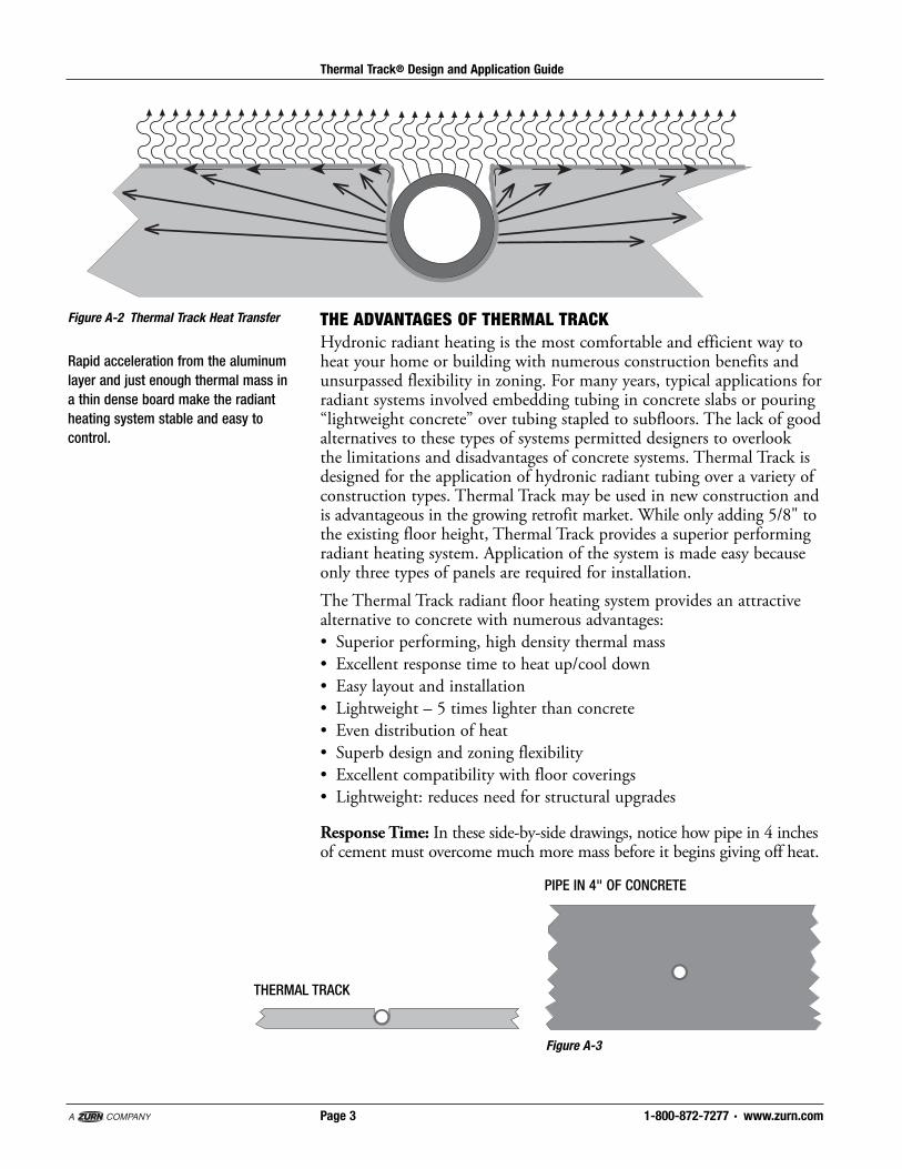
STEADY STATE PER FOR MANCEChart C-1 shows the steady state per for mance of Thermal Track. To theleft are the BTU/sq.ft./hour; the lines rep re sent the re sis tance of the floorcoverings on top of Thermal Track, and on the bot tom is the av er agewater tem per a ture required to achieve the out put. The chart is read byse lect ing the correct BTU re quire ment and then moving hor i zon tal ly untilthe line in di cat ing the cor rect R-Value of the floor as sem bly on top ofThermal Track is en coun tered. At that point, drop down ver ti cal ly to seeav er age water tem per a ture. (See Appendix A on page 26 for typical R-values of flooring goods and materials.)
HEAT LOSSAs with all floor heating jobs, a detailed and ac cu rate heat loss must becal cu lat ed in order to de ter mine prop er de sign con di tions. Re fer to the1999 Ra di ant Pan el As so ci a tion Guide lines For The In stal la tion Of Radi antPanel Sys tems for stan dards on in su la tion and heat loss. The maximumrecommended supply water temperature for Thermal Track is 150°F.
Chart C-1
Installers Note: Re mem ber averagewa ter temperature means the averageof the sup ply and re turn water tem per -atures flow ing to and from the loop.Typically, Thermal Track is designedwith a 20°F tem per a ture drop. Thismeans the supply water temperaturewould typically be 10°F higher thanthe average water temperature.
Installers and Designers Note:Perform the heat loss of the structureat the design stage. This way selectionof floor coverings can be made with therequirements of the sys tem in mind. Ifthe heat loss is too high, add insulationor auxiliary heat. In a very high heat lossroom, Thermal Track might be addedto the walls or ceilings for extra heat.
R-VALUE OF FLOOR AS SEM BLIESWhile Thermal Track will work with a wide variety of floor coverings overthe top of the panels it is important to realize that all floor coverings offera resistance to heat trans fer as measured typically by their R-Value. As withall radiant systems, the higher the R-Value of the floor cov er ing the higherthe average water temperature it takes to overcome this resistance and togenerate the desired amount of heat. If the R-value of any covering on topof Thermal Track be comes excessive, as in any radiant heating system,per for mance will be compromised due to lack of heat transfer, or byexceeding the 150°F maximum supply water tem per a ture. Chart C-1can be used to estimate system output with different floor cov er ings.
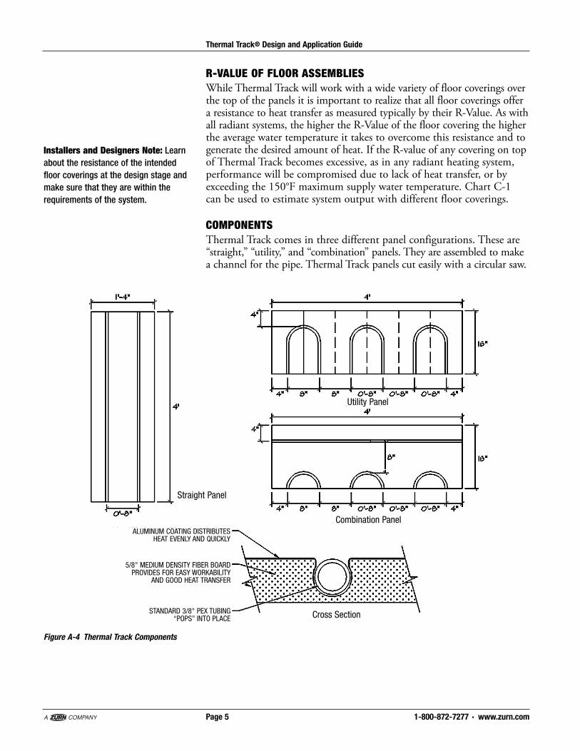
COMPONENTSThermal Track comes in three different panel configurations. These are“straight,” “util i ty,” and “combination” panels. They are assembled to makea channel for the pipe. Thermal Track panels cut easily with a circular saw.
1-800-872-7277 · www.zurn.comPage 5
Thermal Track® Design and Application Guide
Installers and Designers Note: Learnabout the resistance of the intendedfloor coverings at the design stage andmake sure that they are within therequirements of the system.
Straight Panel
Utility Panel
Combination Panel
Cross Section
Figure A-4 Thermal Track Components
ALUMINUM COATING DISTRIBUTESHEAT EVENLY AND QUICKLY
5/8" MEDIUM DENSITY FIBER BOARDPROVIDES FOR EASY WORKABILITY
AND GOOD HEAT TRANSFER
STANDARD 3/8" PEX TUBING “POPS” INTO PLACE
1-800-872-7277 · www.zurn.comPage 6
Thermal Track® Design and Application Guide
THERMAL TRACK PRODUCT HANDLING INFORMATIONNominal Dimensions: Each panel is 16" x 48" x 5/8" thick, or 5.333square feet per panelWeight: Approximately 2.5 lbs. per square foot, 13.3 lbs. per panelPallet Size: 4' x 4' x 24" tall (3 Thermal Track panels to a row, 32 rows high)Approximate Pallet Weight: 1280 lbs.Approximate Truckload Quantities: 16,885.44 square feet or 33 pallets,42,214 lbs.Pallet Appearance: Shrink wrapped, corner protected, col or-codedcorners by part numberRecommended Product Mix: Straight 70%, Combination 15%,Utility 15%; Allow 10% overage.
THERMAL TRACK STORAGEThermal Track should be stored in a temperate, dry place (40°F-90°F).Avoid pro longed exposure to sunlight. Do not store in a damp location.
ESTIMATING THE RE QUIRED NUMBER OF THERMAL TRACK PANELSFor simple and fast in stal la tion, it is highly rec om mend ed that a full ThermalTrack layout be used which in di cates precise panel and tub ing layout. Aplan is recommended for the first few jobs.For experienced installers, cal cu late the net square footage of each roomand multiply by the following fac tors: Straight – 0.133 Utility – 0.028Combination – 0.028Example: For a 600 sq. ft. room, multiplying 600 by 0.133 gives approxi -mately 80 straight panels. Mul ti ply ing 600 by 0.028 gives 17 Utility pieces.Mul ti ply ing 600 by 0.028 gives 17 Combination panels. It is al ways rec om mend ed that a 10% material overage be added to the estimation.
TUBINGThermal Track is designed for use with 3/8" nominal ASTM F-876Zurn PEX (cross-linked polyethylene) with an average outer diametermeasuring .5". Loops shall never be over 250 feet including the leadersto manifolds. For areas with heat loss greater than 25 BTU/sq. ft., loopsshall never be over 200 feet. This is due to high pressure drops and watervelocity as shown in Chart C-2* below (shaded area over 25 BTU/sq. ft.).Fric tion losses in chart are approximate; actual friction losses depend onfluid viscosity and tem per a ture.

TUBING, cont’d.Once the room square footage is determined, multiply the total by 1.5.Example: For a 600 sq. ft. room, multiplying 600 by 1.5 gives 900 linealfeet of 3/8" Zurn PEX tubing. This room would require four loops at225 feet each. Alternatively, three 250-foot loops and one 150-foot loopcould be used, provided that means were provided to balance the flow tothe different loops by bal anc ing valves.
1-800-872-7277 · www.zurn.comPage 7
Thermal Track® Design and Application Guide
*Shaded area in Chart C-2 – 250' Loop(shown below) indicates high pres suredrop. It is rec om mend ed to use theshorter 200' loop length in this case,as shown in the second chart.
Thermal Track 250' Loops 20°F Temp. Drop*
BTU/Sq. Ft. 10 15 20 25 30 35 40
Friction Loss (Ft. Head) 2.22 4.7 8.01 12.1 16.96 22.8 28.87
Water Speed (Ft./Second) 0.6 0.9 1.2 1.5 1.8 2.1 2.4
GPM Per Loop 0.18 0.27 0.36 0.45 0.54 0.63 0.72
*Shaded area indicates high head loss.
Thermal Track 200' Loops 20°F Temp. Drop
BTU/Sq. Ft. 10 15 20 25 30 35 40
Friction Loss (Ft. Head) 0.98 2.07 3.53 5.33 7.47 9.93 12.72
Water Speed (Ft./Second) 0.45 0.68 0.90 1.13 1.35 1.58 1.80
GPM Per Loop 0.14 0.20 0.27 0.34 0.41 0.47 0.54
Chart C-2 3/8" Zurn PEX Flow and Pressure Loss Data
SPACING OF PANELSThe actual width of each panel is 15-7/8" which provides a built-in gapbetween panels for expansion at different temperatures.
OVERVIEW OF FLOOR SURFACE REQUIREMENTSNote: See also the specific application drawings and notes for installingThermal Track that follow in this manual.
Subfloor Requirements – GeneralThe surface of the subfloor must be flat. The requirement for flatness isdefined as the maximum difference between two adjacent high pointsand the intermediate low point. The maximum acceptable difference inlevel is 3/16 of an inch in a 10-foot radius.Fill excessive voids or low areas using a leveling compound. Allow theleveling com pound to dry thoroughly before beginning the installation.Check with the leveling compound manufacturer to be sure it is appropriatefor the application. High areas can be ground down or floated over witha self-leveling compound.The surface of the floor must be clean and dry.
Contractors Note: Be sure to followall instructions elsewhere in this manualre gard ing protecting the panel fromprolonged moisture contact. If theseinstructions are not followed, expansionof greater magnitude could createundesirable effects.

1-800-872-7277 · www.zurn.comPage 8
Thermal Track® Design and Application Guide
OVERVIEW OF FLOOR SURFACE REQUIREMENTS, cont’d.
Subfloor Requirements – Wood SubfloorsWood subfloors must have a stable moisture content between 6-10 percent.Creaking subfloors must be repaired before installation. If the subfloor sags,inspect the joists below for twists or weakness. If the subfloor is cuppedor uneven at the joints, recheck the moisture content of the subfloor to besure it is in the 6-10 percent range. Check for excessive moisture in the crawlspace or basement and look for other signs of a potential water problem.High areas are sanded or planed, low areas patched or filled with anappropriate leveling compound, or covered with a rigid underlayment.When using a leveling compound, be sure to follow the man u fac tur er’srecommenda tions, and allow the compound to dry completely beforestarting to install the floor.
Subfloor Requirements – Concrete SubfloorsSee specific details that follow in the application section of this manual.
Equipment Required For InstallationThe following is necessary for the installation of Thermal Track:• Table or circular saw. A carbide blade is recommended.• Electric or cordless drill gun with No. 2 Phillips bit and 5/8" drill bitfor supply and return bury points.
• Rubber or hard hide mallet• Chalk line, marking pencils and square.• Vacuum cleaner to clean grooves.• 6" pieces of 3/8" Zurn Pex tubing to align grooves.
Recommended Optional Items:• Stand up drill• Tubing uncoiler
Installers Note: Thermal Track cutseasily with a quality circular saw blade.Pieces fre quent ly must be cut to providean accurate fit for each room. It isimportant that they be cut squarely tokeep the alignment of grooves accuratein the installation. If you are installinglarge areas of Thermal Track you maywish to invest in a stand-up drill so thatyou do not have to bend over to setevery screw when gluing and screwingThermal Track to a subfloor. Cut short(6") piec es of Zurn PEX pipe. These canbe used to align the grooves of thepanels during installation by snap pingthem into the grooves with 3" in thegroove on each panel. Once the panelis secured they must be removed priorto the installation of the pipe.

LAYOUT AND INSTALLATIONInstallation Step 1: Uti li ze a plan lay out, determine pan els need ed (seema te ri al takeoff ) and tubing lengths re quired. Be sure to al ways use goodjudge ment in al low ing enough tub ing at ends for lead ers up to man i folds.A plan should in di cate which type of sys tem will be im ple ment ed (seecon struc tion meth ods).
1-800-872-7277 · www.zurn.comPage 9
Thermal Track® Design and Application Guide
MANIFOLD 1
LEADERS TO MANIFOLD
DRILL HOLES TO ROUTE TUBINGBELOW FLOOR
LOOP A: 248 FT.
Panel ScheduleType Quantity
Straight 36
Utility 4
Combo 4
Installation Step 2: Begin the Thermal Track lay out by start ing at thebe gin ning of the sup ply run into the space and run ning panels along thepe rim e ter of the heat ed space to the area of high est heat loss.
PARTIAL UTILITY PANEL
COMBINATION PANEL
STRAIGHT PANEL

1-800-872-7277 · www.zurn.comPage 10
Thermal Track® Design and Application Guide
DETAIL SHOWING SPAC ING BETWEEN PANELSThis gap is “built-in” to stan dard panel dimensions (15-7/8" panel width).
UTILITY OR COMBINATION PANEL
STRAIGHT PANEL
UTILITY OR COMBINATION PANEL
1/8" SPACING BETWEEN ALL PANELS
STRAIGHT PANELS
Installation Step 3: Add utility panels and straight panels working yourway back away from the area of heat loss. Once all panels are in place, drillholes (subfloor with ac cess ap pli ca tion) or route leader back to man i foldvia cus tom grooves or grout (slab or ex ist ing subfloor ap pli ca tion) for supplyand re turn lead ers to man i folds.

Installation Step 4: Feed supply tubing (enough to route to manifold)through drilled sup ply hole be low the floor. Tubing may then be “popped”into grooves after all grooves have been thor ough ly cleaned. Once tubinghas been rout ed back to re turn hole, cut enough to route to return man i fold.
1-800-872-7277 · www.zurn.comPage 11
Thermal Track® Design and Application Guide
LEADERS TO MANIFOLDDRILL HOLES TO ROUTE TUBINGBELOW FLOOR
ADDITIONAL APPLICATION GUIDELINESSpecial Coverage AreasIn ar eas of special coverage such as show er ba sins using tile grout as abase, tubing may be rout ed to and from Thermal Track in order toaccom mo date de sired coverage.
TRANSITION TUBING TO AND FROMSHOWER MORTAR BED
Installers Note: Thermal Track has analuminum Warmcoat™ metal layerthat is slit for the grooves. It isdesigned to be folded down into thegrooves and pressed to the side as thetubing is pushed into the groove.There is, intentionally, a tight tolerancebetween the 3/8" Zurn PEX tubing andthe slightly undercut groove. Thisallows the tubing to be retained in thegrooves once it is pushed in place.Usually, this only requires "walking thetubing into the groove." Occasionallytubing installation may require the useof a rubber or hide mallet to force thetubing in place in the grooves. Afterinstalling a loop of tubing, always walkthe loop and make sure the tubing isfully in the groove for the entire lengthof the groove. This is very important!The top of the tubing should be justbelow the level of the top of theThermal Track, and fully retained inthe groove.
1-800-872-7277 · www.zurn.comPage 12
Thermal Track® Design and Application Guide
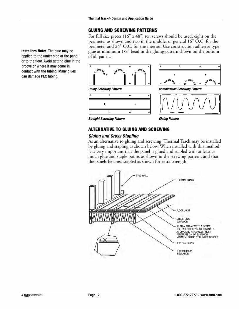
GLUING AND SCREW ING PATTERNSFor full size pieces (16" x 48") ten screws should be used, eight on thepe rim e ter as shown and two in the mid dle, or general 16" O.C. for thepe rim e ter and 24" O.C. for the interior. Use con struc tion adhesive typeglue at min i mum 1/8" bead in the gluing pattern shown on the bot tomof all panels.
Utility Screwing Pattern Combination Screwing Pattern
Straight Screwing Pattern Gluing Pattern
ALTERNATIVE TO GLUING AND SCREWINGGluing and Cross StaplingAs an alternative to gluing and screwing, Thermal Track may be installedby gluing and stapling as shown below. When installed with this method,it is very important that the panel is glued and stapled with at least asmuch glue and staple points as shown in the screwing pattern, and thatthe panels be cross stapled as shown for extra strength.
THERMAL TRACK
STUD WALL
FLOOR JOIST
STRUCTURALSUBFLOOR
AS AN ALTERNATIVE TO A SCREW, USE TWO CLOSELY SPACED STAPLES AT OPPOSING 45° ANGLES. MUST PENETRATE 3/4 OF SUBFLOOR MINIMUM. GLUING STILL MUST BE USED.
3/8" PEX TUBING
R-19 MINIMUMINSULATION
Installers Note: The glue may beapplied to the under side of the panelor to the floor. Avoid getting glue in thegroove or where it may come incontact with the tubing. Many gluescan damage PEX tubing.
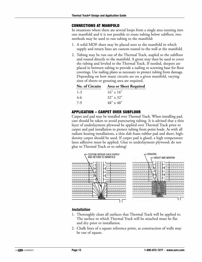
CONNECTIONS AT MANIFOLDIn situations where there are several loops from a single area running intoone manifold and it is not possible to route tubing below subfloor, twomethods may be used to run tubing to the manifold:1. A solid MDF sheet may be placed next to the manifold in whichsupply and return lines are custom routed to the wall at the manifold.
2. Tubing may be run out of the Thermal Track, stapled to the subfloorand routed directly to the manifold. A grout may then be used to coverthe tubing and leveled to the Thermal Track. If needed, sleepers areplaced in between tubing to provide a nailing or screwing base for floorcoverings. Use nailing plates as necessary to protect tubing from damage.Depending on how many circuits are on a given manifold, varyingsizes of sheets or grouting area are required.No. of Circuits Area or Sheet Required1-3 16" x 16"4-6 32" x 32"7-9 48" x 48"
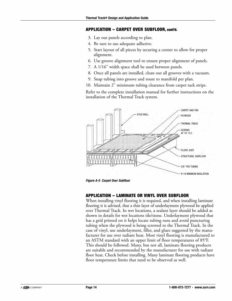
APPLICATION – CARPET OVER SUBFLOORCarpet and pad may be installed over Thermal Track. When installing pad,care should be taken to avoid puncturing tubing. It is advised that a thinlayer of underlayment plywood be applied over Thermal Track prior tocarpet and pad installation to protect tubing from point loads. As with allradiant heating installations, a thin slab foam rubber pad and short, high-density carpet should be used. If carpet pad is glued, a high temperaturelatex adhesive must be applied. Glue to underlayment plywood; do notglue to Thermal Track or to tubing!
1-800-872-7277 · www.zurn.comPage 13
Thermal Track® Design and Application Guide
CUSTOM GROOVE EACH SUPPLYAND RETURN TO MANIFOLD
SPACERSGROUT AND MORTAR
Installation1. Thoroughly clean all surfaces that Thermal Track will be applied to.The surface to which Thermal Track will be attached must be flatand dry prior to installation.
2. Chalk lines of a square reference point, as construction of walls maybe out of square.
1-800-872-7277 · www.zurn.comPage 14
Thermal Track® Design and Application Guide
APPLICATION – LAMINATE OR VINYL OVER SUBFLOORWhen installing vinyl flooring it is required, and when installing laminateflooring it is advised, that a thin layer of underlayment plywood be appliedover Thermal Track. In wet locations, a sealant layer should be added asshown in details for wet locations tile/stone. Underlayment plywood thathas a grid printed on it helps locate tubing runs and avoid puncturingtubing when the plywood is being screwed to the Thermal Track. In thecase of vinyl, use underlayment, filler, and glues suggested by the manu -fac turer for use over radiant heat. Most vinyl flooring is manufactured toan ASTM standard with an upper limit of floor temperatures of 85°F.This should be followed. Many, but not all, laminate flooring productsare suitable and recommended by the manufacturer for use with radiantfloor heat. Check before installing. Many laminate flooring products havefloor temperature limits that need to be observed as well.
Figure A-5 Carpet Over Subfloor
STUD WALL
STRUCTURAL SUBFLOOR
3/8" PEX TUBING
FLOOR JOIST
THERMAL TRACK
CARPET AND PAD
PLYWOOD
SCREWSAT 16" O.C.
R-19 MINIMUM INSULATION
APPLICATION – CARPET OVER SUBFLOOR, cont’d.
3. Lay out panels according to plan.4. Be sure to use adequate adhesive.5. Start layout of all pieces by securing a corner to allow for properalignment.
6. Use groove alignment tool to ensure proper alignment of panels.7. A 1/16" width space shall be used between panels.8. Once all panels are installed, clean out all grooves with a vacuum.9. Snap tubing into groove and route to manifold per plan.10. Maintain 2" minimum tubing clearance from carpet tack strips.Refer to the complete installation manual for further instructions on theinstallation of the Thermal Track system.

1-800-872-7277 · www.zurn.comPage 15
Thermal Track® Design and Application Guide
Laminate Installation
Vinyl Installation
STUD WALL
THIN PLYWOOD
3/8" PEX TUBING
FLOOR JOIST
THERMAL TRACK
BLOCK AS NECESSARYFOR INTERIOR SHEATHING
LAMINATE FLOORING
SCREWSAT 16" O.C.
R-19 MINIMUM INSULATION
STRUCTURAL SUBFLOOR
STUD WALL
PLYWOOD OR BACKER BOARDPER VINYL MANUFACTURER’SRECOMMENDATIONS
3/8" PEX TUBING
FLOOR JOIST
THERMAL TRACK
BLOCK AS NECESSARYFOR INTERIOR SHEATHING
VINYL
SCREWSAT 16" O.C.
R-19 MINIMUM INSULATION
STRUCTURAL SUBFLOOR
Installation1. Thoroughly clean all surfaces that Thermal Track will be applied to.The surface to which Thermal Track will be attached must be flat anddry prior to installation.
2. Chalk lines of a square reference point, as construction of walls maybe out of square.
3. Lay out panels according to plan.4. Be sure to use adequate adhesive.5. Start layout of all pieces by securing a corner to allow for properalignment.
6. Use groove alignment tool to ensure proper alignment of panels.7. A 1/16" width space shall be used between panels.8. Once all panels are installed, clean out all grooves with a vacuum.9. Snap tubing into groove and route to manifold per plan.10. Attach underlayment, if required, with care not to puncture tubing.11. Install laminate flooring crosswise to Thermal Track whenever possible.
APPLICATION – LAMINATE OR VINYL OVER SUBFLOOR, cont’d.

1-800-872-7277 · www.zurn.comPage 16
Thermal Track® Design and Application Guide
APPLICATION OPTIONS – WOOD FLOORS OVER THERMAL TRACKThermal Track may be used under wood flooring in several ways:1. Conventional nailed and hardwood type system may be used directlyover Thermal Track with nailing long enough to penetrate subfloor asdescribed in the following section. When wood flooring systems areinstalled directly over Thermal Track, the hydronic heating systemshould employ controls that gradually adjust water temperature goingto the Thermal Track with a reset curve. See details of this method onfollowing pages.
2. Optionally, two layers of 1/2 inch plywood may be floated on top ofthe Thermal Track and strip flooring nailed to it (as shown on thefollowing page) in a method recommended by the National WoodFlooring Association. This method has the advantage that it allows thewood flooring system to float independently from the Thermal Track,but has significant disadvantages in that the extra one inch thicknessof wood limits the output of the system. For example, two layers of1/2" plywood with 3/4" of strip oak flooring has an R-Value of aboutR-2.3. This limits the output of the floor at 150°F water temperatureto about 26 BTU/square foot. A careful heat loss analysis must bedone to see if this method will produce enough heat. If not, anothermethod should be chosen or provisions made for backup heat. Ahydronic control strategy that gradually adjusts water temperaturegoing to the Thermal Track with a reset curve is recommended butnot required.
3. Clip style floating strip flooring systems must be installed directly overThermal Track such that clips will never come in contact with tubing.
4. The preferred wood flooring over any radiant heating system is to usea floating wood floor with a specific warranty for use over radiant floors.Many manufacturers of these products have such a warranty as well ashaving extensive experience both in Europe and North America withradiant heating applications. Edge glued floating engineered woodflooring systems are preferred since they are dimensionally stable, andexpand independently from any thermal mass. Thermal Track shouldbe installed such that the hardwood runs perpendicular to the majorityof the tubing runs.
5. Glued down wood flooring systems are not recommended unless alayer of plywood is first screwed down to the Thermal Track and thewood is attached to the plywood according to the flooring manu fac -turers recommendations for installation over radiant heat.

1-800-872-7277 · www.zurn.comPage 17
Thermal Track® Design and Application Guide
Wood flooring nailed to two layersof plywood.
Plywood laid diagonal to first layerattached with 7/8" screws on 6"grid pattern.
First layer of plywood is “floated”on Thermal Track.
Finished flooring assembly ofstrip wood flooring and plywood“floats” independently on top ofThermal Track.
APPLICATION – HARDWOODS OVER SUBFLOORConventional nailed and hardwood type system may be used directly overThermal Track with nailing long enough to penetrate subfloor.
Installation1. Thoroughly clean all surfaces that Thermal Track will be applied to.2. Chalk lines of a square reference point as construction of walls maybe inconsistent.
3. Lay out panels according to plan.4. Be sure to use adequate adhesive.5. Start layout of all pieces by securing a corner to allow for properalignment.
6. Use groove alignment tool to ensure proper alignment of panels.7. A 1/16" width space shall be used between panels.8. Once all panels are installed, clean out all grooves with a vacuum.9. Snap tubing into groove and route to manifold per plan.10. Care should be taken to avoid nailing tubing.11. Do not end hardwood floor joint at Thermal Track joint.12. Hardwood floor nails should be long enough to penetrate both
hardwood and subfloor.13. Employ controls that gradually adjust water temperature going to
the Thermal Track with a reset curve.
NWFA Double Plywood Floating Method
APPLICATION OPTIONS – WOOD FLOORS OVER THERMAL TRACK, cont’d.

1-800-872-7277 · www.zurn.comPage 18
Thermal Track® Design and Application Guide
STUD WALL HARDWOOD FLOORING
THERMAL TRACK
SCREWS AT 16" O.C.
FLOOR JOIST
STRUCTURAL SUBFLOOR
3/8" PEX TUBING
R-19 MINIMUM INSULATION
2" MALLET-DRIVEN FLOORINGNAILS TO TIGHTEN BOARDS
2-1/2" NAILS USING TAG ATTACHMENTAND NAIL GUN TO MORE FULLYPENETRATE SUBFLOOR
Hardwoods Over Subfloor
14. It is extremely important that the designer knows which way it isdesired that the strip flooring be aligned prior to the design of theThermal Track system since the direction of the Thermal Trackshould run perpendicular to the direction of the strip flooring.
15. Install strip flooring with mallet driven nails and nails penetratingthe Thermal Track 1/2" into the subfloor.
16. Use 15-gauge nails (2.5" with 3/4" floors) to penetrate subfloor.17. A nailer such as the Senco No. SFM40 with tongue and groove
attachment No. SFM40 TG should be used.18. Keep structure humidity within the range specified by the manufacturer.19. Install the wood at the relative humidity recommended by the
manufacturer for the climate involved.20. Use narrower 2"-3 1/2" strips over radiant floors.21. The lessons of local practice and climate should be referenced.22. Make sure the heating system has been running and the space has
been maintained at least 65°F long enough that temperature andhumidity have stabilized to predicted future levels.
23. Let the product acclimatize before installation.
APPLICATION – HARDWOODS OVER SUBFLOOR, cont’d.
1-800-872-7277 · www.zurn.comPage 19
Thermal Track® Design and Application Guide
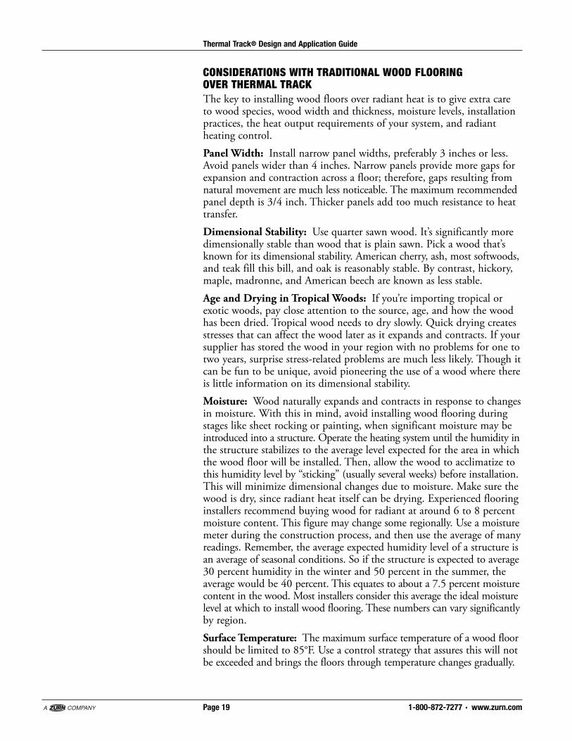
CONSIDERATIONS WITH TRADITIONAL WOOD FLOORING OVER THERMAL TRACKThe key to installing wood floors over radiant heat is to give extra careto wood species, wood width and thickness, moisture levels, installationpractices, the heat output requirements of your system, and radiantheating control.Panel Width: Install narrow panel widths, preferably 3 inches or less.Avoid panels wider than 4 inches. Narrow panels provide more gaps forexpansion and contraction across a floor; therefore, gaps resulting fromnatural movement are much less noticeable. The maximum recommendedpanel depth is 3/4 inch. Thicker panels add too much resistance to heattransfer. Dimensional Stability: Use quarter sawn wood. It’s significantly moredimensionally stable than wood that is plain sawn. Pick a wood that’sknown for its dimensional stability. American cherry, ash, most softwoods,and teak fill this bill, and oak is reasonably stable. By contrast, hickory,maple, madronne, and American beech are known as less stable.Age and Drying in Tropical Woods: If you’re importing tropical orexotic woods, pay close attention to the source, age, and how the woodhas been dried. Tropical wood needs to dry slowly. Quick drying createsstresses that can affect the wood later as it expands and contracts. If yoursupplier has stored the wood in your region with no problems for one totwo years, surprise stress-related problems are much less likely. Though itcan be fun to be unique, avoid pioneering the use of a wood where thereis little information on its dimensional stability.Moisture: Wood naturally expands and contracts in response to changesin moisture. With this in mind, avoid installing wood flooring duringstages like sheet rocking or painting, when significant moisture may beintroduced into a structure. Operate the heating system until the humidity inthe structure stabilizes to the average level expected for the area in whichthe wood floor will be installed. Then, allow the wood to acclimatize tothis humidity level by “sticking” (usually several weeks) before installation.This will minimize dimensional changes due to moisture. Make sure thewood is dry, since radiant heat itself can be drying. Experienced flooringinstallers recommend buying wood for radiant at around 6 to 8 percentmoisture content. This figure may change some regionally. Use a moisturemeter during the construction process, and then use the average of manyreadings. Remember, the average expected humidity level of a structure isan average of seasonal conditions. So if the structure is expected to average30 percent humidity in the winter and 50 percent in the summer, theaverage would be 40 percent. This equates to about a 7.5 percent moisturecontent in the wood. Most installers consider this average the ideal moisturelevel at which to install wood flooring. These numbers can vary signifi cantlyby region.Surface Temperature: The maximum surface temperature of a wood floorshould be limited to 85°F. Use a control strategy that assures this will notbe exceeded and brings the floors through temperature changes gradually.

1-800-872-7277 · www.zurn.comPage 20
Thermal Track® Design and Application Guide
STUD WALL
THIN SET TILE/STONE
THERMAL TRACK
SCREWSAT 16" O.C.
FLOOR JOIST
STRUCTURAL SUBFLOOR
3/8" PEX TUBING
R-19 MINIMUM INSULATION
BACKER BOARD WITHANTI-FRACTURE MEMBRANE
THIN SET APPLICATION:AREAS UNLIKELY TO BE SUBJECTED TO MOISTURE
APPLICATION – TILE OR STONE OVER SUBFLOORFor masonry tile and stone it is recommended that backer board be usedover Thermal Track. Conventional mortar bed or thin set installation maythen be used. In kitchen, baths, laundry, or any other area where watermay be present, water sealant (Nobleseal) shall be used. Where tile isgoing to be thin-set, anti-fracture membrane (Nobleseal) shall be used.
Installation1. Thoroughly clean and level all surfaces that Thermal Track will beapplied to.
2. Chalk lines of a square reference point as construction of walls maybe inconsistent.
3. Lay out panels according to plan.4. Be sure to use adequate adhesive.5. Start layout of all pieces by securing a corner to allow for properalignment.
6. Use groove alignment tool to ensure proper alignment of panels.7. A 1/16" width space shall be used between panels.8. Once all panels are installed, clean out all grooves with a vacuum.9. Snap tubing into groove and route to manifold per plan.10. Maintain 2" minimum tubing clearance when screwing backer
board down.Refer to the complete installation manual for further instructions on theinstallation of the Thermal Track system.
CONSIDERATIONS WITH TRADITIONAL WOOD FLOORING OVER THERMAL TRACK, cont’d.
Humidity Control: In climates with large humidity variations, installhumidity control. In vacation cottages with intermittent use, considerback sealing panels before installation to make them more stable tochanges in moisture in the structure.
Installers Note: Do not omit thebackerboard layer. Do not thinsetdirectly to Thermal Track, the aluminumwill not provide a good bond. Do notinstall crack isolation membranesdirectly to Thermal Track, they will notget a good bond and many of them usematerials that are incompatible forcontact with PEX pipe.

1-800-872-7277 · www.zurn.comPage 21
Thermal Track® Design and Application Guide
Note on Sealing Thermal Track:The aluminum layer on the top of eachThermal Track is highly water resistant.This means that a significant degree ofmoisture protection can be given to thepanel simply by using silicon sealant asa caulk between the panels. Properlyapplied, this will profoundly reduce thelikelihood of water transmission intothe panels. This is not a substitute forrecommended installation methods inwet areas.
TILE AND STONE: MORE DETAILS
STUD WALL
THIN SET TILE/STONE
SCREWSAT 16" O.C.
FLOOR JOIST
STRUCTURAL SUBFLOOR
3/8" PEX TUBING
R-19 MINIMUM INSULATION
BACKER BOARD
NOBLESEAL TS
THERMAL TRACK
THIN SET APPLICATION:AREAS LIKELY TO BE SUBJECTED TO MOISTURE
STUD WALL
TILE/STONE
SCREWSAT 16" O.C.
FLOOR JOIST
STRUCTURAL SUBFLOOR
3/8" PEX TUBING
R-19 MINIMUM INSULATION
BACKER BOARD
MORTAR WITHREINFORCEMENT
THERMAL TRACK
MORTAR APPLICATION:AREAS UNLIKELY TO BE SUBJECTED TO MOISTURE
STUD WALL
TILE/STONE
SCREWSAT 16" O.C.
FLOOR JOIST
STRUCTURAL SUBFLOOR
3/8" PEX TUBING
R-19 MINIMUM INSULATION
NOBLESEAL TS
MORTAR WITHREINFORCEMENT
THERMAL TRACK
MORTAR APPLICATION:AREAS LIKELY TO BE SUBJECTED TO MOISTURE
BACKER BOARD

1-800-872-7277 · www.zurn.comPage 22
Thermal Track® Design and Application Guide
APPLICATION – OVER SLABConcrete RequirementsWhile successful installations of Thermal Track over concrete have been done itis not a preferred application due to the difficulties of sealing concrete andattaching Thermal Track to concrete. Thermal Track may be installed overconcrete using the following method only when the installing parties are willingto assume full responsibility for the installation and all issues regarding moistureand attachment of Thermal Track to concrete. All concrete slabs give offsupplementary moisture whether above, on, or below grade. This can causeproblems for any board product installed over it, including Thermal Track. It isstrongly recommended that all slabs below grade and slabs on gradebe sealed against moisture penetration before installing ThermalTrack. A product such as Hydroment Ultraseal may be used. Remember thatwhile a slab may appear to be or be dry during one time of year, this may changeas environmental conditions change. Below is a procedure for testing moisture ofabove grade slabs such as between floors in commercial construction. When indoubt seal the slab before proceeding with the installation.Initially, check the moisture by taping a 2 ft. x 2-ft. piece of polyethylene film inat least 2 or 3 locations (more in large areas). A rubber-backed mat can be usedinstead of the polyethylene film. Indications of a high moisture content includedarker or discolored concrete, cloudy polyethylene film or condensation on theunderside of the film. A moisture meter may be used, but it can only be used asan indicator because different additives in concrete can cause misleading results.If there are any indications of a high moisture content, use a test method thatwill determine the exact moisture content of the slab based on its dry weight, oruse a calcium chloride test. When using the 6 mil polyethylene vapor barrier, themoisture content must not exceed 2.5% on a dry weight basis. With a calciumchloride test, the maximum acceptable reading is 5 lbs./4 hours/1,000 sq. ft.New concrete slabs and basements must be cured for a minimum of 60 daysprior to installation. Remember, it is recommended that all slabs be sealedagainst moisture penetration before installing Thermal Track.After first determining that the existing or new slab is sufficiently dry, and thensealing the slab, you may proceed with the Thermal Track installation.For masonry tile, stone and vinyl flooring, it is recommended that backer boardbe used over Thermal Track. Conventional mortar bed or thin set installationmay then be used. Use of vinyl floors and associated adhesives and materialsshould be checked for temperature limitations. Conventional and floating typewood floor systems may be use directly over Thermal Track. Floating laminatedwood floors are preferred. Traditional strip wood floors require that 3/4" T&Gplywood is first glued to the slab. Tubing is visible so hardwood may be directlynailed to Thermal Track. See additional notes on installing wood floorselsewhere in this manual. Thermal Track should be installed such that thehardwood runs perpendicular to the majority of the tubing runs.Carpet and pad may be installed as normal over Thermal Track. Carpet padshould avoid being stapled due to tubing being obscured. In cases where extremeweight loads are an tic i pat ed, it is advised that backer board be applied overThermal Track prior to carpet and pad in stal la tion. As with all radiant heatinginstallations, a thin conductive foam rubber pad and short, high density carpetshould be used.
1-800-872-7277 · www.zurn.comPage 23
Thermal Track® Design and Application Guide
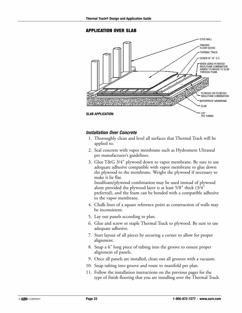
APPLICATION OVER SLAB
Installation Over Concrete1. Thoroughly clean and level all surfaces that Thermal Track will beapplied to.
2. Seal concrete with vapor membrane such as Hydroment Ultrasealper man u fac tur er’s guidelines.
3. Glue T&G 3/4" plywood down to vapor membrane. Be sure to useadequate adhesive com pat i ble with vapor membrane to glue downthe plywood to the membrane. Weight the plywood if necessary tomake it lie flat. Insulfoam/plywood combination may be used instead of plywoodalone provided the plywood layer is at least 5/8" thick (3/4"preferred), and the foam can be bonded with a compatible adhesiveto the vapor membrane.
4. Chalk lines of a square reference point as construction of walls maybe inconsistent.
5. Lay out panels according to plan.6. Glue and screw or staple Thermal Track to plywood. Be sure to useadequate ad he sive.
7. Start layout of all pieces by securing a corner to allow for properalignment.
8. Snap a 6" long piece of tubing into the groove to ensure properalignment of panels.
9. Once all panels are installed, clean out all grooves with a vacuum.10. Snap tubing into groove and route to manifold per plan.11. Follow the installation instructions on the previous pages for the
type of finish flooring that you are installing over the Thermal Track.
STUD WALL
FINISHED FLOOR GOODS
SLAB
3/8" PEX TUBING
SCREW AT 16" O.C.
THERMAL TRACK
WHEN USING PLYWOOD/INSULFOAM COMBINATIONRAMSET PLYWOOD TO SLABTHROUGH FOAM.
PLYWOOD OR PLYWOOD/INSULFOAM COMBINATION
WATERPROOF MEMBRANE
SLAB APPLICATION:
1-800-872-7277 · www.zurn.comPage 24
Thermal Track® Design and Application Guide
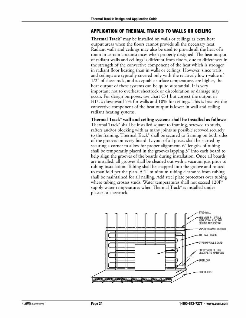
STUD WALL
MINIMUM R-13 WALL INSULATION R-30 FOR CEILING APPLICATION
FLOOR JOIST
VAPOR/RADIANT BARRIER
THERMAL TRACK
GYPSUM WALL BOARD
SUBFLOOR
SUPPLY AND RETURN LEADERS TO MANIFOLD
APPLICATION OF THERMAL TRACK® TO WALLS OR CEILING
Thermal Track® may be installed on walls or ceilings as extra heatoutput areas when the floors cannot provide all the necessary heat.Radiant walls and ceilings may also be used to provide all the heat of aroom in certain circumstances when properly designed. The heat outputof radiant walls and ceilings is different from floors, due to differences inthe strength of the convective component of the heat which is strongerin radiant floor heating than in walls or ceilings. However, since wallsand ceilings are typically covered only with the relatively low r-value of1/2” of sheet rock, and acceptable surface temperatures are higher, theheat output of these systems can be quite substantial. It is veryimportant not to overheat sheetrock or discoloration or damage mayoccur. For design purposes, use chart C-1 but correct the output inBTU’s downward 5% for walls and 10% for ceilings. This is because theconvective component of the heat output is lower in wall and ceilingradiant heating systems.Thermal Track® wall and ceiling systems shall be installed as follows:Thermal Track® shall be installed square to framing, screwed to studs,rafters and/or blocking with as many joints as possible screwed securelyto the framing. Thermal Track® shall be secured to framing on both sidesof the grooves on every board. Layout of all pieces shall be started bysecuring a corner to allow for proper alignment. 6” lengths of tubingshall be temporarily placed in the grooves lapping 3” into each board tohelp align the grooves of the boards during installation. Once all boardsare installed, all grooves shall be cleaned out with a vacuum just prior totubing installation. Tubing shall be snapped into the groove and routedto manifold per the plan. A 1” minimum tubing clearance from tubingshall be maintained for all nailing. Add steel plate protectors over tubingwhere tubing crosses studs. Water temperatures shall not exceed 120F°supply water temperatures when Thermal Track® is installed underplaster or sheetrock.

1-800-872-7277 · www.zurn.comPage 25
Thermal Track® Design and Application Guide
CAUTIONS AND LIMITATIONS OF USE:
General Caution:As with any radiant heating system, do not install Thermal Track® without anaccurate room-by-room heat loss analysis for the structure to be heated, as wellas a design/layout for Thermal Track® that takes into account the resistance andheat transfer of the actual floor coverings. If Thermal Track® cannot provide allthe necessary heat, make provisions for additional backup heat
Installer Caution:This manual is deemed to be current at the time of publication. It is theinstaller’s responsibility to install according to the most current ApplicationGuide. This guide does not purport to address all relevant issues; it assumes aknowledge of good practice in both hydronics and construction methods.Installers should always consult all relevant local, regional and national codes,and adhere to good construction practice. Thermal Track® should only beinstalled by knowledgeable, qualified installers. Thermal Track® installationsfrequently require the coordination of trades. These are, most typically,mechanical and flooring trades. Any issues regarding this coordination should beworked out in advance. Failure to follow the instructions of this guide, failure toadhere to relevant local, regional and national codes, failure to coordinate trades,and failure to follow good construction practice may cause an unsatisfactoryresult. See also “limitations of use” elsewhere in this publication. The limitationsand instructions of use for PEX pipe and all other hydronic componentsprovided by the manufacturers must also be referenced and followed duringinstallation; this manual does not address many aspects of a hydronicinstallation.Limitations of Use:Thermal Track® is designed for interior use only, and is to be installed only ondry substrata once a structure is closed in, protected from the environment, andwill remain dry. Thermal Track® is not intended as, or rated as, a replacement orsubstitution for a structural subfloor. The BTU output of Thermal Track® islimited by the R-values of the finish goods applied over it and by therecommended and available water temperatures. Thermal Track® is not intendedfor use with finish goods that are incompatible with the temperatures andconditions present in a radiant heating system. Thermal Track® is not intended asa finish floor, and should be left uncovered and unprotected only duringinstallation.
1-800-872-7277 · www.zurn.comPage 26
Thermal Track® Design and Application Guide
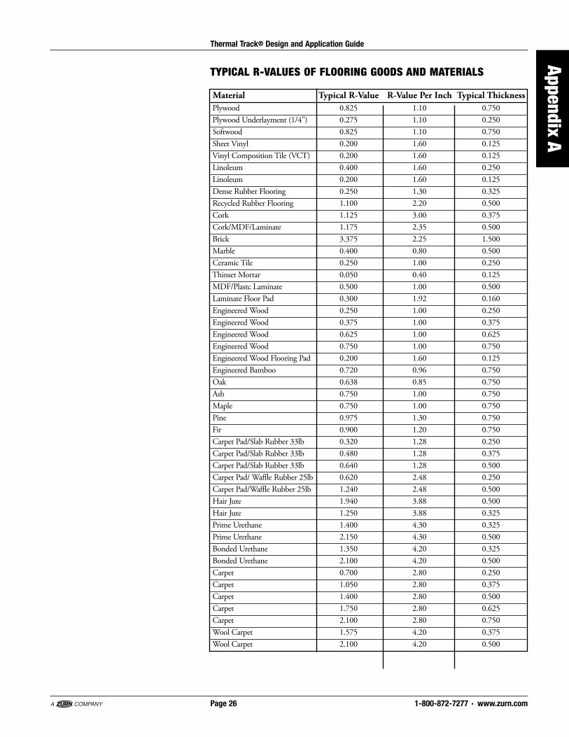
Material Typical R-Value R-Value Per Inch Typical ThicknessPlywood 0.825 1.10 0.750Plywood Underlayment (1/4") 0.275 1.10 0.250Softwood 0.825 1.10 0.750Sheet Vinyl 0.200 1.60 0.125Vinyl Composition Tile (VCT) 0.200 1.60 0.125Linoleum 0.400 1.60 0.250Linoleum 0.200 1.60 0.125Dense Rubber Flooring 0.250 1.30 0.325Recycled Rubber Flooring 1.100 2.20 0.500Cork 1.125 3.00 0.375Cork/MDF/Laminate 1.175 2.35 0.500Brick 3.375 2.25 1.500Marble 0.400 0.80 0.500Ceramic Tile 0.250 1.00 0.250Thinset Mortar 0.050 0.40 0.125MDF/Plastc Laminate 0.500 1.00 0.500Laminate Floor Pad 0.300 1.92 0.160Engineered Wood 0.250 1.00 0.250Engineered Wood 0.375 1.00 0.375Engineered Wood 0.625 1.00 0.625Engineered Wood 0.750 1.00 0.750Engineered Wood Flooring Pad 0.200 1.60 0.125Engineered Bamboo 0.720 0.96 0.750Oak 0.638 0.85 0.750Ash 0.750 1.00 0.750Maple 0.750 1.00 0.750Pine 0.975 1.30 0.750Fir 0.900 1.20 0.750Carpet Pad/Slab Rubber 33lb 0.320 1.28 0.250Carpet Pad/Slab Rubber 33lb 0.480 1.28 0.375Carpet Pad/Slab Rubber 33lb 0.640 1.28 0.500Carpet Pad/ Waffle Rubber 25lb 0.620 2.48 0.250Carpet Pad/Waffle Rubber 25lb 1.240 2.48 0.500Hair Jute 1.940 3.88 0.500Hair Jute 1.250 3.88 0.325Prime Urethane 1.400 4.30 0.325Prime Urethane 2.150 4.30 0.500Bonded Urethane 1.350 4.20 0.325Bonded Urethane 2.100 4.20 0.500Carpet 0.700 2.80 0.250Carpet 1.050 2.80 0.375Carpet 1.400 2.80 0.500Carpet 1.750 2.80 0.625Carpet 2.100 2.80 0.750Wool Carpet 1.575 4.20 0.375Wool Carpet 2.100 4.20 0.500
TYPICAL R-VALUES OF FLOORING GOODS AND MATERIALS
Appendix A

ZURN INDUSTRIES, LLCRADIANT HEATING SYSTEMS1801 PITTSBURGH AVENUEERIE, PA 16502PHONE: 1-800-872-7277FAX: 1-800-209-2148www.zurn.com
In Canada:ZURN INDUSTRIES LIMITED3544 NASHUA DRIVEMISSISSAUGA, ONTARIO CANADA L4V 1L2PHONE: 905/405-8272FAX: 905/405-1292
Form No. ZMKTG370-07, 5/12