Thermal Stress Update - PPGbuyat.ppg.com/glasstechlib/85_Thermal Stress Update-13June2008.pdf ·...
39
Thermal Stress Update Vitro Architectural Glass PAGE 1 OF 39 Glass Technical Document | TD-109 INTRODUCTION Vitro Architectural Glass (formerly PPG Industries) has for many years recommended that early design considerations regarding the use of glass on commercial projects include evaluation of potential thermal stress breakage. Thermally induced glass breakage is recognized and well understood in the glass industry. Procedures to help design influentials evaluate these risks have long been offered by Vitro. The basis and methodology included in previous versions of this document, such as TSR’s 130 and 230 for monolithic and insulating glass respectively, remain valid and applicable and are continued in this document. Completely satisfactory performance can be and has been achieved when attention is given to the thermal stress performance of the glass in the design stage of the project. Performing a thermal stress analysis, using the appropriate design factors, will lead architects and design professionals to the proper glass recommendation to ensure that the glass performs under the expected thermal loads. When installations experience thermal stress breakage problems, glass damage, improper glazing practice, inappropriate thermal stress analysis, or the complete absence of a thermal stress analysis are invariably involved. The purpose of this document is to provide: An overview and perspective on thermal stress. Thermal Stress Factors for Vitro’s 6mm (1/4”) thick glass products, including new coated and tinted products. Clarification of the use of the thermal stress procedures and interpretation of the results. Updated product specific guidelines. What’s New in This Document? The following additions and changes have been made to this version of the Thermal Stress Update: Vitro Optiblue® tinted glass and Solarban® z50 coated glass have been added Procedures to perform a thermal stress analysis for insulating glass units incorporating selected coatings on both the outdoor and indoor glass lites have been added. Selected 3mm (1/8”) thick products have been removed. The number of Vitro glass product combinations available when combining different glass substrates and coatings makes it impractical to address them all in this document. Users are encouraged to use Vitro’s Thermal Stress Analysis computer program, which is available on Vitro’s website and can be used to perform a thermal stress analysis for virtually any of Vitro glass products. Additional information about this valuable tool, including a link to the program, can be found on page 35 of this document.
Transcript of Thermal Stress Update - PPGbuyat.ppg.com/glasstechlib/85_Thermal Stress Update-13June2008.pdf ·...
Thermal Stress Update
Vitro Architectural Glass PAGE 1 OF 39
Glass Technical Document | TD-109
INTRODUCTION
Vitro Architectural Glass (formerly PPG Industries) has for many years recommended that early design
considerations regarding the use of glass on commercial projects include evaluation of potential thermal stress
breakage. Thermally induced glass breakage is recognized and well understood in the glass industry. Procedures to
help design influentials evaluate these risks have long been offered by Vitro. The basis and methodology included in
previous versions of this document, such as TSR’s 130 and 230 for monolithic and insulating glass respectively,
remain valid and applicable and are continued in this document.
Completely satisfactory performance can be and has been achieved when attention is given to the thermal stress
performance of the glass in the design stage of the project. Performing a thermal stress analysis, using the
appropriate design factors, will lead architects and design professionals to the proper glass recommendation to
ensure that the glass performs under the expected thermal loads. When installations experience thermal stress
breakage problems, glass damage, improper glazing practice, inappropriate thermal stress analysis, or the complete
absence of a thermal stress analysis are invariably involved.
The purpose of this document is to provide:
An overview and perspective on thermal stress.
Thermal Stress Factors for Vitro’s 6mm (1/4”) thick glass products, including new coated and tinted
products.
Clarification of the use of the thermal stress procedures and interpretation of the results.
Updated product specific guidelines.
What’s New in This Document?
The following additions and changes have been made to this version of the Thermal Stress Update:
Vitro Optiblue® tinted glass and Solarban® z50 coated glass have been added
Procedures to perform a thermal stress analysis for insulating glass units incorporating selected
coatings on both the outdoor and indoor glass lites have been added.
Selected 3mm (1/8”) thick products have been removed.
The number of Vitro glass product combinations available when combining different glass
substrates and coatings makes it impractical to address them all in this document. Users are
encouraged to use Vitro’s Thermal Stress Analysis computer program, which is available on
Vitro’s website and can be used to perform a thermal stress analysis for virtually any of Vitro
glass products. Additional information about this valuable tool, including a link to the program,
can be found on page 35 of this document.
Thermal Stress Update
Vitro Architectural Glass PAGE 2 OF 39
Glass Technical Document | TD-109
OTHER IMPORTANT DESIGN ISSUES
Thermal stress is only one glass design consideration. Other important issues, not addressed in this
document, include:
Aesthetics
Wind and Snow Loads
ASTM E 1300 – Standard Practice for Determining Load Resistance of Glass in
Buildings can be used to evaluate specified glass products subjected to uniform wind and
snow loads.
Thermal and Optical Performance
Vitro publishes thermal and optical properties for its glass products based on simulations
using the LBNL Window program. This program can be downloaded freely from the
LBNL Window and Daylighting web site, which can be accessed using the following link:
LBNL Window Program
Vitro invites you to use its web based Glass Performance Calculator to simulate the
thermal and optical properties of many of its glass products, including monolithic,
insulating glass, fritted glass and laminated glass applications. The program can be
accessed using the following link:
Glazing Systems
Energy and Safety Glazing Codes
It is the design professional’s responsibility to ensure compliance with all of these requirements. Vitro has
long provided technical guidelines and offered specific assistance on these and other glass related issues.
Consult your Vitro representative for assistance.
On going efforts by ASTM have resulted in a new Standard Practice for Determining the Resistance
of Single Glazed Annealed Architectural Flat Glass to Thermal Loadings (E2431-06). Vitro fully
supports and participates in the ASTM effort to develop a comprehensive practice for the
evaluation of thermal stresses in glass, in which this first version of E2431 is the initial step.
Thermal Stress Update
Vitro Architectural Glass PAGE 3 OF 39
Glass Technical Document | TD-109
THERMAL STRESS
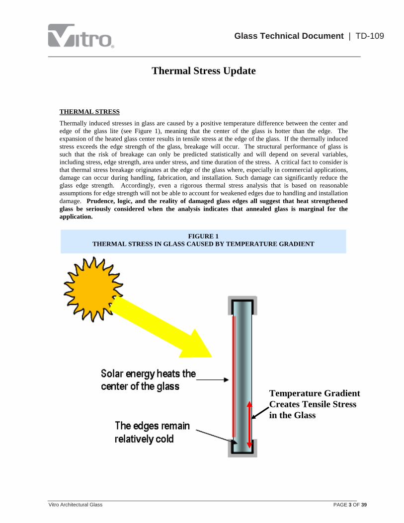
Thermally induced stresses in glass are caused by a positive temperature difference between the center and
edge of the glass lite (see Figure 1), meaning that the center of the glass is hotter than the edge. The
expansion of the heated glass center results in tensile stress at the edge of the glass. If the thermally induced
stress exceeds the edge strength of the glass, breakage will occur. The structural performance of glass is
such that the risk of breakage can only be predicted statistically and will depend on several variables,
including stress, edge strength, area under stress, and time duration of the stress. A critical fact to consider is
that thermal stress breakage originates at the edge of the glass where, especially in commercial applications,
damage can occur during handling, fabrication, and installation. Such damage can significantly reduce the
glass edge strength. Accordingly, even a rigorous thermal stress analysis that is based on reasonable
assumptions for edge strength will not be able to account for weakened edges due to handling and installation
damage. Prudence, logic, and the reality of damaged glass edges all suggest that heat strengthened
glass be seriously considered when the analysis indicates that annealed glass is marginal for the
application.
Temperature Gradient
Creates Tensile Stress
in the Glass
FIGURE 1
THERMAL STRESS IN GLASS CAUSED BY TEMPERATURE GRADIENT
Thermal Stress Update
Vitro Architectural Glass PAGE 4 OF 39
Glass Technical Document | TD-109
Glass thermal stresses are influenced by a number of product and environmental factors. The most significant
contributors to thermal stresses are:
Glass Type
Coating Type and Coating Location
Exterior Shading Patterns
Interior Solar Control Applications (drapes, venetian blinds)
Heating Register Location and Orientation
Glass Type
For purposes of this discussion, three types of glass are considered: clear glass, tinted glass, and spectrally
selective glass. The temperature gradient that causes thermal stress typically arises when the sun heats the
exposed area of cool or cold glass. The speed and amount of the temperature increase is directly related to
the absorption of the glass. Because tinted glass, and especially spectrally selective glass, derive their
improved solar performance by absorbing solar radiation, they are much more susceptible to thermal stress
problems than clear glass.
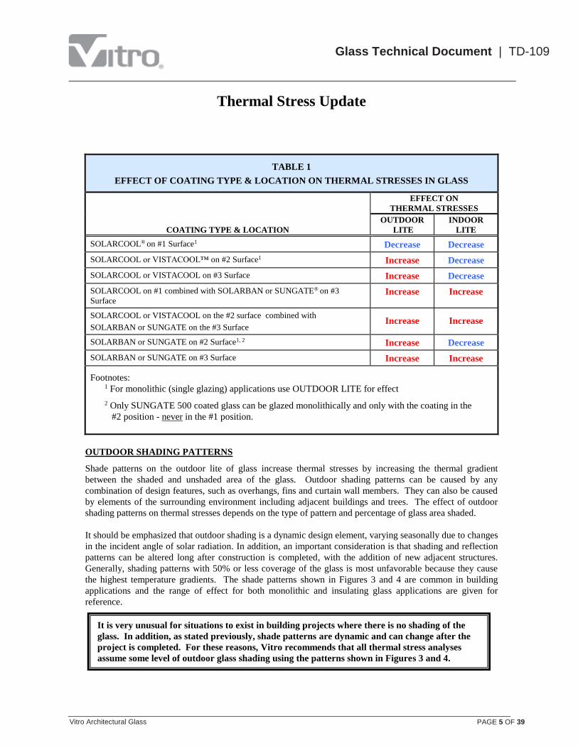
Coating Type and Coating Location
Reflective and low emissivity coatings improve solar performance by both reflecting and absorbing solar
radiation. As discussed, increased absorption will lead to increased glass temperatures. The effect of
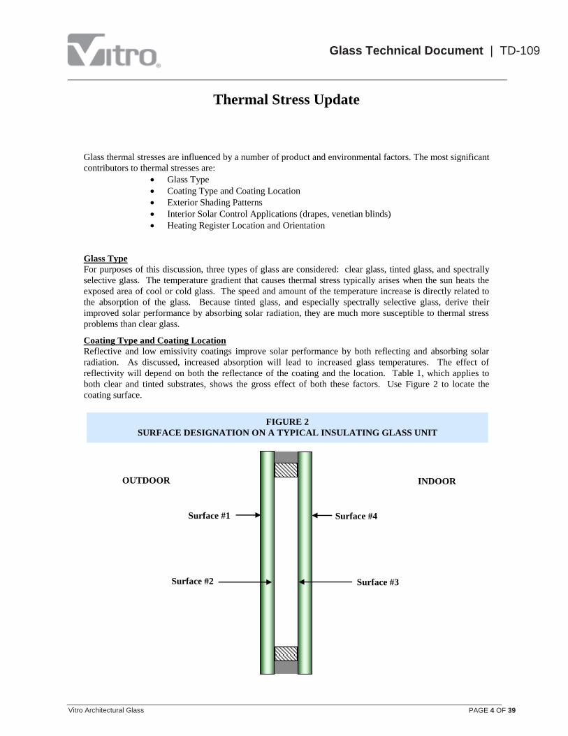
reflectivity will depend on both the reflectance of the coating and the location. Table 1, which applies to
both clear and tinted substrates, shows the gross effect of both these factors. Use Figure 2 to locate the
coating surface.
OUTDOOR
S INDOOR
Surface #1
Surface #2
Surface #4
Surface #3
FIGURE 2
SURFACE DESIGNATION ON A TYPICAL INSULATING GLASS UNIT
Thermal Stress Update
Vitro Architectural Glass PAGE 5 OF 39
Glass Technical Document | TD-109
TABLE 1
EFFECT OF COATING TYPE & LOCATION ON THERMAL STRESSES IN GLASS
COATING TYPE & LOCATION
EFFECT ON
THERMAL STRESSES
OUTDOOR
LITE
INDOOR
LITE
SOLARCOOL® on #1 Surface1 Decrease Decrease
SOLARCOOL or VISTACOOL™ on #2 Surface1 Increase Decrease
SOLARCOOL or VISTACOOL on #3 Surface Increase Decrease
SOLARCOOL on #1 combined with SOLARBAN or SUNGATE® on #3
Surface Increase Increase
SOLARCOOL or VISTACOOL on the #2 surface combined with
SOLARBAN or SUNGATE on the #3 Surface Increase Increase
SOLARBAN or SUNGATE on #2 Surface1, 2 Increase Decrease
SOLARBAN or SUNGATE on #3 Surface Increase Increase
Footnotes:
1 For monolithic (single glazing) applications use OUTDOOR LITE for effect
2 Only SUNGATE 500 coated glass can be glazed monolithically and only with the coating in the
#2 position - never in the #1 position.
OUTDOOR SHADING PATTERNS
Shade patterns on the outdoor lite of glass increase thermal stresses by increasing the thermal gradient
between the shaded and unshaded area of the glass. Outdoor shading patterns can be caused by any
combination of design features, such as overhangs, fins and curtain wall members. They can also be caused
by elements of the surrounding environment including adjacent buildings and trees. The effect of outdoor
shading patterns on thermal stresses depends on the type of pattern and percentage of glass area shaded.
It should be emphasized that outdoor shading is a dynamic design element, varying seasonally due to changes
in the incident angle of solar radiation. In addition, an important consideration is that shading and reflection
patterns can be altered long after construction is completed, with the addition of new adjacent structures.
Generally, shading patterns with 50% or less coverage of the glass is most unfavorable because they cause
the highest temperature gradients. The shade patterns shown in Figures 3 and 4 are common in building
applications and the range of effect for both monolithic and insulating glass applications are given for
reference.
It is very unusual for situations to exist in building projects where there is no shading of the
glass. In addition, as stated previously, shade patterns are dynamic and can change after the
project is completed. For these reasons, Vitro recommends that all thermal stress analyses
assume some level of outdoor glass shading using the patterns shown in Figures 3 and 4.

Thermal Stress Update
Vitro Architectural Glass PAGE 6 OF 39
Glass Technical Document | TD-109
VERTICAL
75%
SHADED 0.6 0.7
HORIZONTAL DIAGONAL
25%
SHADED
FACTOR
VARIES
FROM
0.6
TO
3.5
0.6
3.5 1.7
2.8
VERTICAL DIAGONAL
HORIZONTAL DIAGONAL
VERTICAL HORIZONTAL
0.8 0.8 1.5
4.5 3.5 2.5
75%
SHADED
25%
SHADED
75%
SHADED
25%
SHADED
1.5 1.0 0.6
3.0 4.8 6.5
FACTOR
VARIES
FROM
0.8
TO
4.5
FACTOR
VARIES
FROM
0.6
TO
6.5
FIGURE 3
Outdoor Shading Patterns and Associated Approximate Thermal Stress Factors for Insulating Glass Units
Select the shading pattern which most closely approximates project conditions. Thermal stress increases
as percent shaded area decreases. Thermal stress increases going down the table.
DOUBLE DIAGONAL

Thermal Stress Update
Vitro Architectural Glass PAGE 7 OF 39
Glass Technical Document | TD-109
VERTICAL
75%
SHADED 0.0 0.1
HORIZONTAL DIAGONAL
25%
SHADED
FACTOR
VARIES
FROM
0.0
TO
1.0
0.0
1.0 0.4
0.8
VERTICAL DIAGONAL
HORIZONTAL DIAGONAL
VERTICAL HORIZONTAL
0.0 0.2 0.3
1.5 1.2 1.0
75%
SHADED
25%
SHADED
75%
SHADED
25%
SHADED
0.4 0.2 0.0
1.2 2.0 2.3
FACTOR
VARIES
FROM
0.0
TO
1.5
FACTOR
VARIES
FROM
0.0
TO
2.3
FIGURE 4
Outdoor Shading Patterns and Associated Approximate Thermal Stress Factors for Monolithic (Single) Glazing
Select the shading pattern which most closely approximates project conditions. Thermal stress increases
as percent shaded area decreases. Thermal stress increases going down the table.
DOUBLE DIAGONAL

Thermal Stress Update
Vitro Architectural Glass PAGE 8 OF 39
Glass Technical Document | TD-109
INDOOR SHADING DEVICES
The widespread use of insulating glass makes it important to consider the elements of interior design and
their potential effect on the INDOOR lite of the insulating glass unit. The known or likely use of a variety of
common interior window treatments is a critical design element.
Indoor shading devices increase the temperature of the central area of the glass in two ways:
By reflecting solar radiation back through the glass
By reducing the convection and conduction of heat through the glass
The effect of the indoor shading device is dependent on the type and color of device used and the amount of
ventilation that exists within the air space between the shading device and the glass. Ventilating the air space
will help to reduce edge stresses. The glass to shade space should be at least two inches and vented; a vented
glass to shade space of six inches is preferable. Natural ventilation can be provided by leaving at least an
inch between shading devices and surrounding construction at the sill and two inches at the head. As glass to
shade spacing is decreased, edge stress increases. The following indoor shading devices are listed in order of
increasing glass stress.
TABLE 2
RELATIVE EFFECT OF INTERIOR SHADING DEVICE ON GLASS STRESS
INTERIOR SHADING DEVICE EFFECT ON GLASS STRESS
None Least Stress
Dark open weave draperies
Light open-weave draperies
Dark closed-weave draperies
Light closed-weave draperies
Dark venetian blinds
Light venetian blinds Maximum Stress
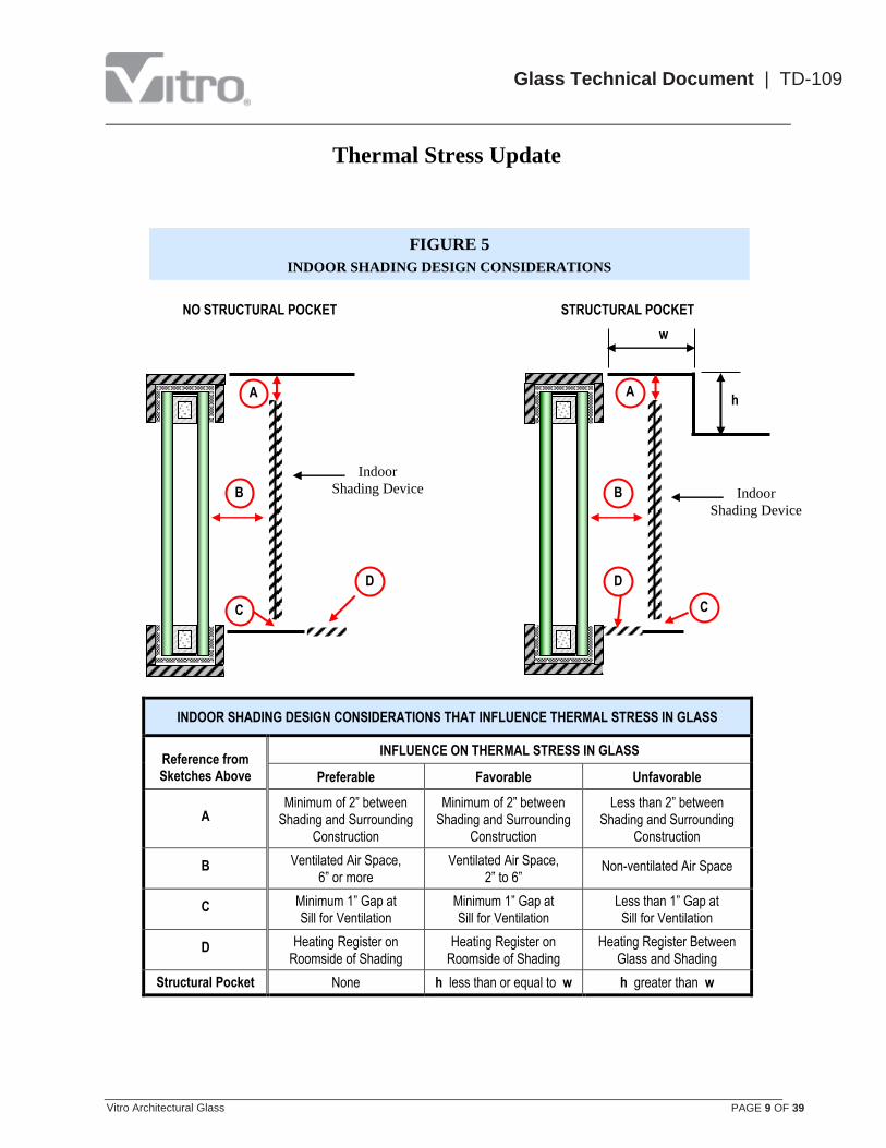
HEATING REGISTER LOCATION AND ORIENTATION
Heating registers that direct warm air against cold glass can induce thermal breakage. Also, if the heating
register is located between the interior shading device and the glass, the trapped heat can cause the center of
the glass to become excessively warm and lead to glass breakage. Accordingly, heating registers should be
located on the room side of the interior shading, never between the interior shading and the glass. Register
vanes should direct warm air away from the glass.
Figure 5 on page 9 may offer some guidance in determining indoor shading and heating register design
elements that minimize thermal stresses in the glass.
Thermal Stress Update
Vitro Architectural Glass PAGE 9 OF 39
Glass Technical Document | TD-109
INDOOR SHADING DESIGN CONSIDERATIONS THAT INFLUENCE THERMAL STRESS IN GLASS
Reference from Sketches Above
INFLUENCE ON THERMAL STRESS IN GLASS
Preferable Favorable Unfavorable
A
Minimum of 2” between
Shading and Surrounding
Construction
Minimum of 2” between
Shading and Surrounding
Construction
Less than 2” between
Shading and Surrounding
Construction
B Ventilated Air Space,
6” or more
Ventilated Air Space,
2” to 6” Non-ventilated Air Space
C Minimum 1” Gap at
Sill for Ventilation
Minimum 1” Gap at
Sill for Ventilation
Less than 1” Gap at
Sill for Ventilation
D Heating Register on
Roomside of Shading
Heating Register on
Roomside of Shading
Heating Register Between
Glass and Shading
Structural Pocket None h less than or equal to w h greater than w
FIGURE 5
INDOOR SHADING DESIGN CONSIDERATIONS
A
B
C
D
A
NO STRUCTURAL POCKET
h
w
STRUCTURAL POCKET
B
C
D
Indoor
Shading Device Indoor
Shading Device
Thermal Stress Update
Vitro Architectural Glass PAGE 10 OF 39
Glass Technical Document | TD-109
FRAMING SYSTEM
Framing with low heat capacity tends to minimize thermal stresses. For example, lock-strip gaskets tend to
reduce thermal stresses because they are black and somewhat insulating. Metal glazing rabbets and frames,
together with rubber gaskets, is the most typically used framing system. Thermal stresses will tend to
increase as the thickness of the metal increases. Metal framing systems that include integral thermal barriers
may reduce thermal stresses in the indoor glass of the insulating glass unit; conversely, this type of framing
may increase thermal stress in the outdoor glass of the insulating glass unit.
Massive concrete or metal frames in thermal contact with glazing rabbets have great heat capacity and will
result in increased thermal stress in the glass when the concrete or metal becomes cold and does not warm up
as fast as the central area of the glass unit when exposed to solar energy.
Framing systems that are designed to make glazing easy will reduce the possibility of edge or impact damage
to the glass unit during installation. Increasing the rabbet width and depth reduces tolerance problems and
facilitates the glazing of the units, thus reducing the likelihood of glass edge damage.
Framing systems that require glass units to be joggle set increase the possibility of edge damage, unless each
unit is cushioned adequately against impact, pressure and abrasion.
Figure 6 on page 11 is offered for guidance in evaluating the relative effects of the framing system on the
expected thermal stresses in the glass.
Very Important:
Glass edge damage will significantly reduce the glass edge
strength, possibly by 50% or more depending on the severity of
the damage.
Damaged glass edges will lead to an increased probability of
glass breakage due to thermal stresses, as well as due to other
possible sources of glass stress.
Vitro’s recommendations to resist thermal stress breakage are
based on clean-cut, undamaged glass edges.

Thermal Stress Update
Vitro Architectural Glass PAGE 11 OF 39
Glass Technical Document | TD-109
FIGURE 6
FRAMING SYSTEM CONSIDERATIONS
UNFAVORABLE
Massive
Metal or Masonry
TYPICAL
Metal Framing
FAVORABLE
Structural Gasket

Thermal Stress Update
Vitro Architectural Glass PAGE 12 OF 39
Glass Technical Document | TD-109
THERMAL STRESS ANALYSIS
Vitro’s methodology (examples given later in this document) for estimating thermal stresses, which has been
widely used in the glass industry for years, is based on determining the effect of the various design and
environmental factors. This cumulative stress factor is then multiplied by the glass thermal stress factor to
arrive at the estimated in-service thermal stress. Finally, the estimated thermal stress is used to calculate the
predicted probability of glass breakage that is used to make the glass treatment recommendation, based on
the design professional’s acceptable level of glass breakage for the project.
Typically, Charts 1 & 2 for insulating and monolithic glass respectively, are used to determine whether glass
strengthening is required. Charts 1 & 2 are a “go, no-go” tool based on a probability of breakage of 8 per
1000 and are appropriate if this level of predicted breakage is acceptable to the responsible design
professional. Vitro can calculate the numeric probability of glass breakage based on the expected thermal
stress, if required.
Obviously, the recommendation resulting from the analysis is valid only if the conditions assumed to make
the analysis are representative or more severe than the actual in-service conditions. The reality is that in-
service conditions are often different than the assumptions. Some of these differences are beyond the
designer’s control or even his or her ability to anticipate them; other changes can and should reasonably be
anticipated and considered in reaching a final decision. For example, if the intended design does not include
interior shading and a thermal stress analysis is performed based on this assumption, the results may indicate
that annealed glass is adequate. If the decision is later made to install indoor shading devices, the consequent
increased thermal stress may lead to unexpected glass breakage. A more conservative approach in the design
stage is to assume some type of indoor shading, which could prevent this type of situation. In situations
where reliable design conditions are unavailable, good engineering judgment is to assume the most
conservative (i.e., severe) design conditions that could be reasonably expected.
GUIDELINES
Over the years Vitro has provided guidelines for various Vitro glass products to assist our customers make
quick, first level judgments concerning the need to provide additional fabrication to meet thermal stress
requirements. Such guidelines can only be prepared based on assumed glazing and installation conditions
and must be used with care and good judgment. Updated guidelines are offered in Table 18, together with
the assumptions given in Table 17 that were used to prepare them.
Very Important:
The guidelines in Table 18 are offered with the expectation that they
will be used with good judgment and caution.
They are offered as a point of departure to make an initial
assessment of potential thermal stress problems.
They are NOT a substitute for an in depth thermal stress analysis.

Thermal Stress Update
Vitro Architectural Glass PAGE 13 OF 39
Glass Technical Document | TD-109
Tables 3 – 16, and Tables Tf, Tg, and Th are used to determine the various values required in the thermal
stress analysis procedure. Tables 3 – 16 contain the stress factors for the various Vitro glass products, both
coated and uncoated. Tables 3 and 4 apply to monolithic glass applications, and Tables 5 -16 apply to
insulating glass unit applications. In addition to the glass stress factors, Tables 5 – 16 include the
appropriate Installation Condition Table reference (Tf, Tg, or Th) to use based on the specified glass.
Tables Tf, Tg, and Th contain the Installation Conditions and associated factors.
TABLE 3
STRESS FACTORS FOR MONOLITHIC APPLICATIONS
WITH CLEAR AND TINTED GLASS
GLASS DESCRIPTION
GLASS THICKNESS ALL OTHER NORTH
INCHES MM STRESS (PSI) STRESS (PSI)
CLEAR ¼ 6.0 220 110
ATLANTICA® ¼ 6.0 800 370
AZURIA® ¼ 6.0 790 370
CARIBIA® ¼ 6.0 820 380
GRAYLITE® ¼ 6.0 900 420
OPTIBLUE® ¼ 6.0 410 200
SOLARBRONZE® ¼ 6.0 590 280
SOLARGRAY® ⅛ 3.0 480 230
¼ 6.0 690 320
OPTIGRAY® ¼ 6.0 990 460
SOLEXIA® ¼ 6.0 620 290
STARPHIRE® ¼ 6.0 60 40
Thermal Stress Update
Vitro Architectural Glass PAGE 14 OF 39
Glass Technical Document | TD-109
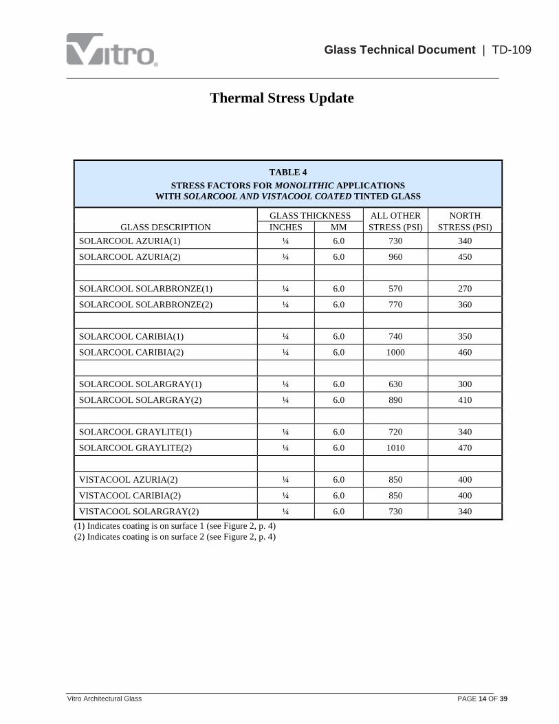
TABLE 4
STRESS FACTORS FOR MONOLITHIC APPLICATIONS
WITH SOLARCOOL AND VISTACOOL COATED TINTED GLASS
GLASS DESCRIPTION
GLASS THICKNESS ALL OTHER NORTH
INCHES MM STRESS (PSI) STRESS (PSI)
SOLARCOOL AZURIA(1) ¼ 6.0 730 340
SOLARCOOL AZURIA(2) ¼ 6.0 960 450
SOLARCOOL SOLARBRONZE(1) ¼ 6.0 570 270
SOLARCOOL SOLARBRONZE(2) ¼ 6.0 770 360
SOLARCOOL CARIBIA(1) ¼ 6.0 740 350
SOLARCOOL CARIBIA(2) ¼ 6.0 1000 460
SOLARCOOL SOLARGRAY(1) ¼ 6.0 630 300
SOLARCOOL SOLARGRAY(2) ¼ 6.0 890 410
SOLARCOOL GRAYLITE(1) ¼ 6.0 720 340
SOLARCOOL GRAYLITE(2) ¼ 6.0 1010 470
VISTACOOL AZURIA(2) ¼ 6.0 850 400
VISTACOOL CARIBIA(2) ¼ 6.0 850 400
VISTACOOL SOLARGRAY(2) ¼ 6.0 730 340
(1) Indicates coating is on surface 1 (see Figure 2, p. 4)
(2) Indicates coating is on surface 2 (see Figure 2, p. 4)

Thermal Stress Update
Vitro Architectural Glass PAGE 15 OF 39
Glass Technical Document | TD-109
TABLE 5
STRESS FACTORS FOR INSULATING GLASS UNITS
WITH CLEAR AND TINTED GLASS
GLASS DESCRIPTION
GLASS THICKNESS ALL OTHER NORTH FOR IG -
INCHES MM STRESS (PSI) STRESS (PSI) USE TABLE
CLEAR INDOOR LITE ¼ 6.0 220 110 Tf
OUTDOOR LITE
CLEAR ¼ 6.0 240 120 Tf
ATLANTICA ¼ 6.0 810 380 Tf
AZURIA ¼ 6.0 810 380 Tf
CARIBIA ¼ 6.0 840 390 Tf
GRAYLITE ¼ 6.0 920 430 Tf
OPTIBLUE ¼ 6.0 430 210 Tf
SOLARBRONZE ¼ 6.0 610 290 Tf
SOLARGRAY ¼ 6.0 710 330 Tf
OPTIGRAY ¼ 6.0 1000 460 Tf
SOLEXIA ¼ 6.0 640 300 Tf
STARPHIRE ¼ 6.0 60 40 Tf
Thermal Stress Update
Vitro Architectural Glass PAGE 16 OF 39
Glass Technical Document | TD-109
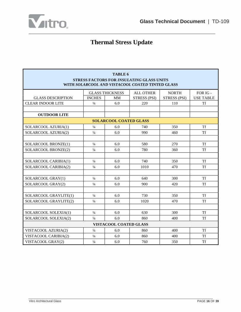
TABLE 6
STRESS FACTORS FOR INSULATING GLASS UNITS
WITH SOLARCOOL AND VISTACOOL COATED TINTED GLASS
GLASS DESCRIPTION
GLASS THICKNESS ALL OTHER NORTH FOR IG -
INCHES MM STRESS (PSI) STRESS (PSI) USE TABLE
CLEAR INDOOR LITE ¼ 6.0 220 110 Tf
OUTDOOR LITE
SOLARCOOL COATED GLASS
SOLARCOOL AZURIA(1) ¼ 6.0 740 350 Tf
SOLARCOOL AZURIA(2) ¼ 6.0 990 460 Tf
SOLARCOOL BRONZE(1) ¼ 6.0 580 270 Tf
SOLARCOOL BRONZE(2) ¼ 6.0 780 360 Tf
SOLARCOOL CARIBIA(1) ¼ 6.0 740 350 Tf
SOLARCOOL CARIBIA(2) ¼ 6.0 1010 470 Tf
SOLARCOOL GRAY(1) ¼ 6.0 640 300 Tf
SOLARCOOL GRAY(2) ¼ 6.0 900 420 Tf
SOLARCOOL GRAYLITE(1) ¼ 6.0 730 350 Tf
SOLARCOOL GRAYLITE(2) ¼ 6.0 1020 470 Tf
SOLARCOOL SOLEXIA(1) ¼ 6.0 630 300 Tf
SOLARCOOL SOLEXIA(2) ¼ 6.0 860 400 Tf
VISTACOOL COATED GLASS
VISTACOOL AZURIA(2) ¼ 6.0 860 400 Tf
VISTACOOL CARIBIA(2) ¼ 6.0 860 400 Tf
VISTACOOL GRAY(2) ¼ 6.0 760 350 Tf

Thermal Stress Update
Vitro Architectural Glass PAGE 17 OF 39
Glass Technical Document | TD-109
TABLE 7
STRESS FACTORS FOR INSULATING GLASS UNITS
WITH SUNGATE 500 COATING ON SURFACE #2 OR #3
GLASS DESCRIPTION
GLASS THICKNESS ALL OTHER NORTH FOR IG -
INCHES MM STRESS (PSI) STRESS (PSI) USE TABLE
OUTDOOR LITE: CLEAR GLASS WITH SUNGATE 500 ON THE # 2 SURFACE
INDOOR LITE: CLEAR
SUNGATE 500(2)CLEAR ¼ 6.0 350 170 Tg
CLEAR ¼ 6.0 220 110 Tg
SUNGATE 500 ON THE # 3 SURFACE
INDOOR LITE
CLEAR GLASS WITH
SUNGATE 500 COATING
ON #3 SURFACE
3/32 2.5 200 100 Tf
⅛ 3.0 240 120 Tf
¼ 6.0 290 140 Tf
OUTDOOR LITE
CLEAR 3/32 2.5 100 60 Tf
⅛ 3.0 160 80 Tf
¼ 6.0 240 120 Tf
ATLANTICA ¼ 6.0 830 390 Tf
AZURIA ⅛ 3.0 720 340 Tf
¼ 6.0 820 380 Tf
CARIBIA ¼ 6.0 850 400 Tf
GRAYLITE ¼ 6.0 930 430 Tf
OPTIBLUE ¼ 6.0 440 210 Tf
SOLARBRONZE ¼ 6.0 630 300 Tf
SOLARGRAY ¼ 6.0 730 340 Tf
OPTIGRAY ¼ 6.0 1010 470 Tf
SOLEXIA ¼ 6.0 660 310 Tf
STARPHIRE ¼ 6.0 70 50 Tf

Thermal Stress Update
Vitro Architectural Glass PAGE 18 OF 39
Glass Technical Document | TD-109
TABLE 8
STRESS FACTORS FOR INSULATING GLASS UNITS
WITH SUNGATE 100 COATING ON SURFACE #2 0R #3
GLASS DESCRIPTION
GLASS THICKNESS ALL OTHER NORTH FOR IG -
INCHES MM STRESS (PSI) STRESS (PSI) USE TABLE
OUTDOOR LITE: CLEAR GLASS WITH SUNGATE 100 ON THE # 2 SURFACE
INDOOR LITE: CLEAR
SUNGATE 100(2)CLEAR ¼ 6.0 400 190 Tg
CLEAR ¼ 6.0 220 110 Tg
SUNGATE 100 ON THE #3 SURFACE
INDOOR LITE
SUNGATE 100(3)CLEAR ¼ 6.0 270 130 As shown for
OUTDOOR lite
OUTDOOR LITE
CLEAR ¼ 6.0 270 130 Tg
ATLANTICA ¼ 6.0 870 400 Th
AZURIA ¼ 6.0 860 400 Th
CARIBIA ¼ 6.0 890 410 Th
GRAYLITE ¼ 6.0 970 450 Th
OPTIBLUE ¼ 6.0 480 230 Th
SOLARBRONZE ¼ 6.0 670 310 Th
SOLARGRAY ¼ 6.0 770 360 Th
OPTIGRAY ¼ 6.0 1040 480 Th
SOLEXIA ¼ 6.0 700 330 Th
STARPHIRE ¼ 6.0 80 50 Tg

Thermal Stress Update
Vitro Architectural Glass PAGE 19 OF 39
Glass Technical Document | TD-109
TABLE 9
STRESS FACTORS FOR CLEAR INSULATING GLASS
WITH SOLARBAN 60 COATING ON SURFACE #2
GLASS DESCRIPTION
GLASS THICKNESS ALL OTHER NORTH FOR IG -
INCHES MM STRESS (PSI) STRESS (PSI) USE TABLE
OUTDOOR LITE
SOLARBAN 60(2) CLEAR ⅛ 3.0 210 100 Tg
¼ 6.0 490 230 Tg
SOLARBAN 60(2) STARPHIRE ⅛ 3.0 120 60 Tg
¼ 6.0 300 140 Tg
SOLARBAN 60 ON TINTED GLASS SUBSTRATES*
SOLARBAN 60(2)ATLANTICA ¼ 6.0 940 440 Th
SOLARBAN 60(2)AZURIA ¼ 6.0 940 440 Th
SOLARBAN 60(2)CARIBIA ¼ 6.0 940 440 Th
SOLARBAN 60(2)BRONZE ¼ 6.0 810 380 Th
SOLARBAN 60(2)GRAY ⅛ 3.0 710 330 Th
¼ 6.0 830 390 Th
INDOOR LITE
CLEAR ⅛ 3.0 170 90 As shown for
OUTDOOR Lite ¼ 6.0 220 110
* Solarban 60 coated tinted glass availability is on a project basis only. It is recommended
that availability be confirmed prior to specifying or bidding the product for projects.
Thermal Stress Update
Vitro Architectural Glass PAGE 20 OF 39
Glass Technical Document | TD-109
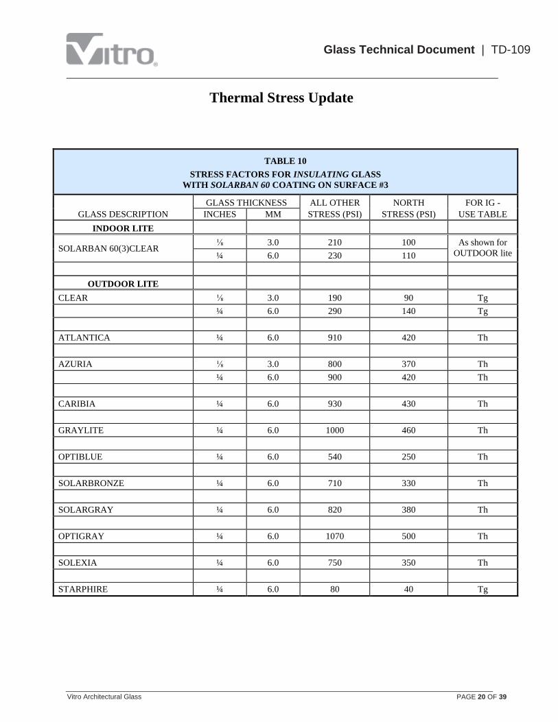
TABLE 10
STRESS FACTORS FOR INSULATING GLASS
WITH SOLARBAN 60 COATING ON SURFACE #3
GLASS DESCRIPTION
GLASS THICKNESS ALL OTHER NORTH FOR IG -
INCHES MM STRESS (PSI) STRESS (PSI) USE TABLE
INDOOR LITE
SOLARBAN 60(3)CLEAR ⅛ 3.0 210 100 As shown for
OUTDOOR lite ¼ 6.0 230 110
OUTDOOR LITE
CLEAR ⅛ 3.0 190 90 Tg
¼ 6.0 290 140 Tg
ATLANTICA ¼ 6.0 910 420 Th
AZURIA ⅛ 3.0 800 370 Th
¼ 6.0 900 420 Th
CARIBIA ¼ 6.0 930 430 Th
GRAYLITE ¼ 6.0 1000 460 Th
OPTIBLUE ¼ 6.0 540 250 Th
SOLARBRONZE ¼ 6.0 710 330 Th
SOLARGRAY ¼ 6.0 820 380 Th
OPTIGRAY ¼ 6.0 1070 500 Th
SOLEXIA ¼ 6.0 750 350 Th
STARPHIRE ¼ 6.0 80 40 Tg

Thermal Stress Update
Vitro Architectural Glass PAGE 21 OF 39
Glass Technical Document | TD-109
TABLE 11
STRESS FACTORS FOR INSULATING GLASS UNITS
WITH SOLARBAN 70XL COATING ON SURFACE #2 OR #3
GLASS DESCRIPTION
GLASS THICKNESS ALL OTHER NORTH FOR IG -
INCHES MM STRESS (PSI) STRESS (PSI) USE TABLE
OUTDOOR LITE: STARPHIRE GLASS WITH SOLARBAN 70XL ON THE # 2 SURFACE
INDOOR LITE: CLEAR
SOLARBAN 70XL(2)
STARPHIRE OUTDOOR LITE ¼ 6.0 340 160 Tg
CLEAR INDOOR LITE ¼ 6.0 220 110 Tg
SOLARBAN 70XL ON THE #3 SURFACE
INDOOR LITE
SOLARBAN 70XL(3)
STARPHIRE ¼ 6.0 230 110
As shown for
OUTDOOR lite
OUTDOOR LITE
CLEAR ¼ 6.0 310 150 Tg
ATLANTICA ¼ 6.0 940 440 Th
AZURIA ¼ 6.0 960 450 Th
CARIBIA ¼ 6.0 960 450 Th
GRAYLITE ¼ 6.0 1040 480 Th
OPTIBLUE ¼ 6.0 560 270 Th
SOLARBRONZE ¼ 6.0 750 350 Th
SOLARGRAY ¼ 6.0 850 400 Th
OPTIGRAY ¼ 6.0 1090 510 Th
SOLEXIA ¼ 6.0 780 370 Th
STARPHIRE ¼ 6.0 80 50 Tg
Thermal Stress Update
Vitro Architectural Glass PAGE 22 OF 39
Glass Technical Document | TD-109
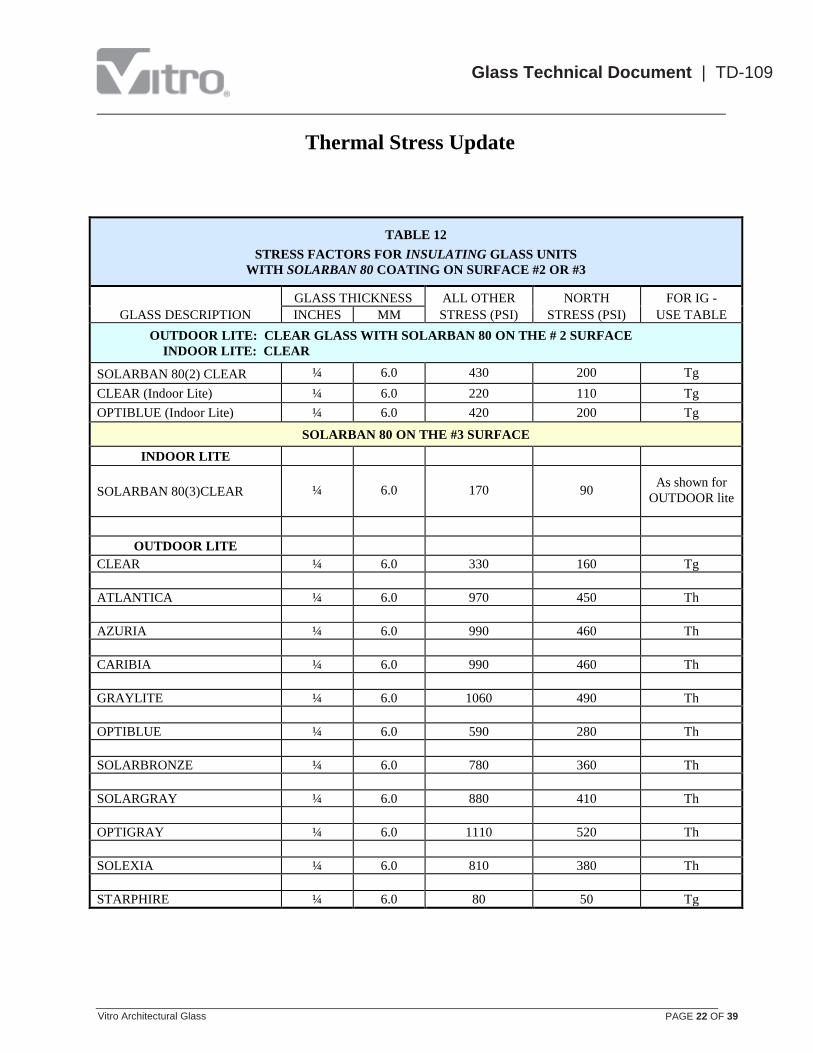
TABLE 12
STRESS FACTORS FOR INSULATING GLASS UNITS
WITH SOLARBAN 80 COATING ON SURFACE #2 OR #3
GLASS DESCRIPTION
GLASS THICKNESS ALL OTHER NORTH FOR IG -
INCHES MM STRESS (PSI) STRESS (PSI) USE TABLE
OUTDOOR LITE: CLEAR GLASS WITH SOLARBAN 80 ON THE # 2 SURFACE
INDOOR LITE: CLEAR
SOLARBAN 80(2) CLEAR ¼ 6.0 430 200 Tg
CLEAR (Indoor Lite) ¼ 6.0 220 110 Tg
OPTIBLUE (Indoor Lite) ¼ 6.0 420 200 Tg
SOLARBAN 80 ON THE #3 SURFACE
INDOOR LITE
SOLARBAN 80(3)CLEAR ¼ 6.0 170 90 As shown for
OUTDOOR lite
OUTDOOR LITE
CLEAR ¼ 6.0 330 160 Tg
ATLANTICA ¼ 6.0 970 450 Th
AZURIA ¼ 6.0 990 460 Th
CARIBIA ¼ 6.0 990 460 Th
GRAYLITE ¼ 6.0 1060 490 Th
OPTIBLUE ¼ 6.0 590 280 Th
SOLARBRONZE ¼ 6.0 780 360 Th
SOLARGRAY ¼ 6.0 880 410 Th
OPTIGRAY ¼ 6.0 1110 520 Th
SOLEXIA ¼ 6.0 810 380 Th
STARPHIRE ¼ 6.0 80 50 Tg
Thermal Stress Update
Vitro Architectural Glass PAGE 23 OF 39
Glass Technical Document | TD-109
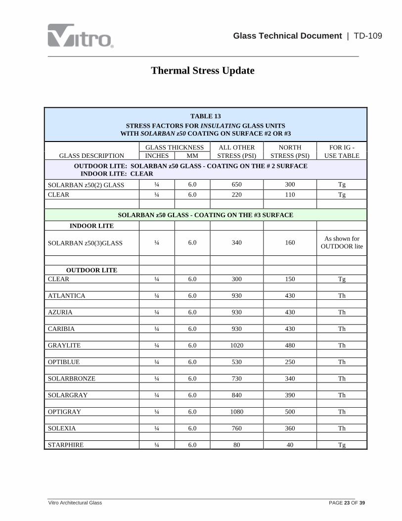
TABLE 13
STRESS FACTORS FOR INSULATING GLASS UNITS
WITH SOLARBAN z50 COATING ON SURFACE #2 OR #3
GLASS DESCRIPTION
GLASS THICKNESS ALL OTHER NORTH FOR IG -
INCHES MM STRESS (PSI) STRESS (PSI) USE TABLE
OUTDOOR LITE: SOLARBAN z50 GLASS - COATING ON THE # 2 SURFACE
INDOOR LITE: CLEAR
SOLARBAN z50(2) GLASS ¼ 6.0 650 300 Tg
CLEAR ¼ 6.0 220 110 Tg
SOLARBAN z50 GLASS - COATING ON THE #3 SURFACE
INDOOR LITE
SOLARBAN z50(3)GLASS ¼ 6.0 340 160 As shown for
OUTDOOR lite
OUTDOOR LITE
CLEAR ¼ 6.0 300 150 Tg
ATLANTICA ¼ 6.0 930 430 Th
AZURIA ¼ 6.0 930 430 Th
CARIBIA ¼ 6.0 930 430 Th
GRAYLITE ¼ 6.0 1020 480 Th
OPTIBLUE ¼ 6.0 530 250 Th
SOLARBRONZE ¼ 6.0 730 340 Th
SOLARGRAY ¼ 6.0 840 390 Th
OPTIGRAY ¼ 6.0 1080 500 Th
SOLEXIA ¼ 6.0 760 360 Th
STARPHIRE ¼ 6.0 80 40 Tg

Thermal Stress Update
Vitro Architectural Glass PAGE 24 OF 39
Glass Technical Document | TD-109
TABLE 14
STRESS FACTORS FOR INSULATING GLASS UNITS WITH SOLARCOOL OR VISTACOOL COATED OUTDOOR GLASS AND SUNGATE 500 COATING ON #3 SURFACE
GLASS DESCRIPTION
GLASS THICKNESS ALL OTHER NORTH FOR IG -
INCHES MM STRESS (PSI) STRESS (PSI) USE TABLE
OUTDOOR LITE: SOLARCOOL OR VISTACOOL COATED GLASS
INDOOR LITE: SUNGATE 500 CLEAR – COATING ON #3 SURFACE
INDOOR LITE
SUNGATE 500(3)CLEAR ¼ 6.0 350 170 As shown for
OUTDOOR lite
OUTDOOR LITE
SOLARCOOL AZURIA(1) ¼ 6.0 760 360 Th
SOLARCOOL AZURIA(2) ¼ 6.0 1010 470 Th
SOLARCOOL BRONZE(1) ¼ 6.0 590 280 Th
SOLARCOOL BRONZE(2) ¼ 6.0 820 390 Th
SOLARCOOL CARIBIA(1) ¼ 6.0 760 360 Th
SOLARCOOL CARIBIA(2) ¼ 6.0 1010 470 Th
SOLARCOOL GRAY(1) ¼ 6.0 650 310 Th
SOLARCOOL GRAY(2) ¼ 6.0 900 420 Th
SOLARCOOL GRAYLITE(1) ¼ 6.0 740 350 Th
SOLARCOOL GRAYLITE(2) ¼ 6.0 1030 480 Th
SOLARCOOL SOLEXIA(1) ¼ 6.0 640 300 Th
SOLARCOOL SOLEXIA(2) ¼ 6.0 870 410 Th
VISTACOOL AZURIA(2) ¼ 6.0 870 410 Th
VISTACOOL CARIBIA(2) ¼ 6.0 870 410 Th
VISTACOOL GRAY(2) ¼ 6.0 770 360 Th
Thermal Stress Update
Vitro Architectural Glass PAGE 25 OF 39
Glass Technical Document | TD-109
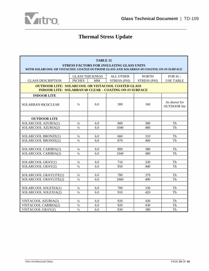
TABLE 15
STRESS FACTORS FOR INSULATING GLASS UNITS WITH SOLARCOOL OR VISTACOOL COATED OUTDOOR GLASS AND SOLARBAN 60 COATING ON #3 SURFACE
GLASS DESCRIPTION
GLASS THICKNESS ALL OTHER NORTH FOR IG -
INCHES MM STRESS (PSI) STRESS (PSI) USE TABLE
OUTDOOR LITE: SOLARCOOL OR VISTACOOL COATED GLASS
INDOOR LITE: SOLARBAN 60 CLEAR – COATING ON #3 SURFACE
INDOOR LITE
SOLARBAN 60(3)CLEAR ¼ 6.0 300 160 As shown for
OUTDOOR lite
OUTDOOR LITE
SOLARCOOL AZURIA(1) ¼ 6.0 800 380 Th
SOLARCOOL AZURIA(2) ¼ 6.0 1040 480 Th
SOLARCOOL BRONZE(1) ¼ 6.0 660 310 Th
SOLARCOOL BRONZE(2) ¼ 6.0 870 400 Th
SOLARCOOL CARIBIA(1) ¼ 6.0 800 380 Th
SOLARCOOL CARIBIA(2) ¼ 6.0 1040 480 Th
SOLARCOOL GRAY(1) ¼ 6.0 710 330 Th
SOLARCOOL GRAY(2) ¼ 6.0 950 440 Th
SOLARCOOL GRAYLITE(1) ¼ 6.0 780 370 Th
SOLARCOOL GRAYLITE(2) ¼ 6.0 1060 490 Th
SOLARCOOL SOLEXIA(1) ¼ 6.0 700 330 Th
SOLARCOOL SOLEXIA(2) ¼ 6.0 910 420 Th
VISTACOOL AZURIA(2) ¼ 6.0 920 430 Th
VISTACOOL CARIBIA(2) ¼ 6.0 920 430 Th
VISTACOOL GRAY(2) ¼ 6.0 830 380 Th
Thermal Stress Update
Vitro Architectural Glass PAGE 26 OF 39
Glass Technical Document | TD-109
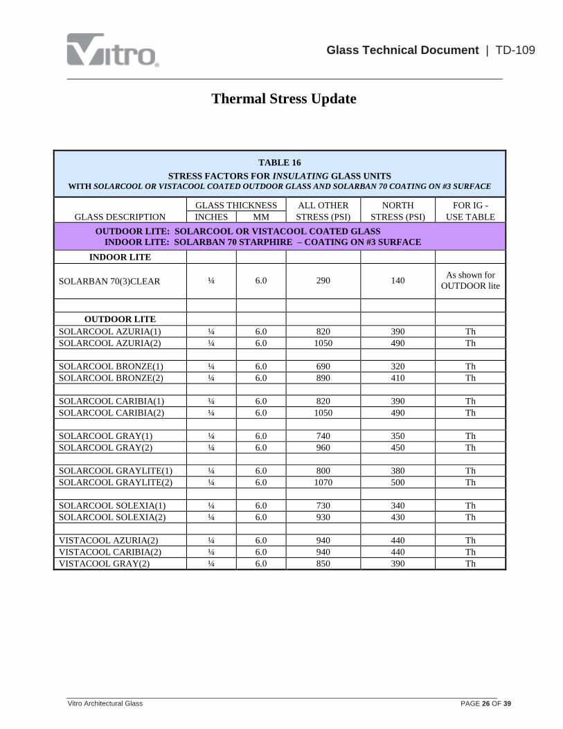
TABLE 16
STRESS FACTORS FOR INSULATING GLASS UNITS WITH SOLARCOOL OR VISTACOOL COATED OUTDOOR GLASS AND SOLARBAN 70 COATING ON #3 SURFACE
GLASS DESCRIPTION
GLASS THICKNESS ALL OTHER NORTH FOR IG -
INCHES MM STRESS (PSI) STRESS (PSI) USE TABLE
OUTDOOR LITE: SOLARCOOL OR VISTACOOL COATED GLASS
INDOOR LITE: SOLARBAN 70 STARPHIRE – COATING ON #3 SURFACE
INDOOR LITE
SOLARBAN 70(3)CLEAR ¼ 6.0 290 140 As shown for
OUTDOOR lite
OUTDOOR LITE
SOLARCOOL AZURIA(1) ¼ 6.0 820 390 Th
SOLARCOOL AZURIA(2) ¼ 6.0 1050 490 Th
SOLARCOOL BRONZE(1) ¼ 6.0 690 320 Th
SOLARCOOL BRONZE(2) ¼ 6.0 890 410 Th
SOLARCOOL CARIBIA(1) ¼ 6.0 820 390 Th
SOLARCOOL CARIBIA(2) ¼ 6.0 1050 490 Th
SOLARCOOL GRAY(1) ¼ 6.0 740 350 Th
SOLARCOOL GRAY(2) ¼ 6.0 960 450 Th
SOLARCOOL GRAYLITE(1) ¼ 6.0 800 380 Th
SOLARCOOL GRAYLITE(2) ¼ 6.0 1070 500 Th
SOLARCOOL SOLEXIA(1) ¼ 6.0 730 340 Th
SOLARCOOL SOLEXIA(2) ¼ 6.0 930 430 Th
VISTACOOL AZURIA(2) ¼ 6.0 940 440 Th
VISTACOOL CARIBIA(2) ¼ 6.0 940 440 Th
VISTACOOL GRAY(2) ¼ 6.0 850 390 Th

Thermal Stress Update
Vitro Architectural Glass PAGE 27 OF 39
Glass Technical Document | TD-109
TABLE - Tf
FOR USE WHEN REFERENCED BY APPROPRIATE STRESS FACTOR TABLE
Factor
Installation Condition Outdoors Indoors 1. Outdoor (Not Spandrels) 0.8 1.0
2. Type of Window (Insulating Glass Unit) 0.2 1.4
3. Framing System Structural Rubber Gaskets -0.2
2
-0.5
Wood Sash -0.1 -0.3
Aluminum or Steel (Tubular) - Thin 0.0 0.0
- Thick (>⅛”) 0.5 1.0
Masonry or Metal (Solid) - Massive 1.0 3.0
4. Outdoor Glazing Stop Color Black -0.2 -0.2
Dark -0.1 -0.1
Light 0.0 0.0
5. Heating Register Location Roomside of Indoor Shading Heat Directed Away from Glass 0.0 0.0
Heat Directed Toward Glass 0.0 0.1
No Indoor Shading Heat Directed Away from Glass 0.1 0.5
Heat Directed Toward Glass 0.2 2.0
Between Glass and Indoor Shading Heat Directed Away from Glass 0.3 2.0
Heat Directed Toward Glass 0.5 3.0
6. Design Winter Temperature (from ASHRAE Handbook) Below -10 F. 1 0.5 3.5
-10 to +10 F. 1 0.5 3.0
+10 to +30 F. 0.5 3.0
Above 30 F. 0.5 2.5
7. Altitude Below 5,000 ft. 0.0 0.0
Above 5,000 ft. 0.3 0.5
8. Adjacent Reflecting Surface None 0.0 0.0
Dark (Smooth) 0.2 0.2
Medium 0.3 0.4
White (Snow) 0.5 0.6
9. Outdoor Shading 2 Vertical, Horizontal, or Diagonal Shadows
0.4 to 2.3 1.0 to 1.5 Vertical & Horizontal
Vertical & Diagonal
Horizontal & Diagonal Shadows 0.4 to 2.5 1.0 to 1.8
Double Diagonal Shadows 1.0 to 3.0 1.0 to 2.5
10. Indoor Shading Outdoor Glass Indoor Glass
Space Between Indoor Glass & Shading
Ventilated Non-Ventilated Ventilated Non-Ventilated
Drapes 6 in. plus 6 in. less 6 in. plus 6 in. less 6 in. plus 6 in. less 6 in. plus 6 in. less
None 0 0 0 0 0 0 0 0
Dark Open Weave 0 0.2 0.3 0.4 0.2 0.2 1.0 2.0
Light Open Weave 0.2 0.4 0.5 0.6 0.8 1.0 1.5 2.5
Dark Closed Weave 0.2 0.5 0.7 0.8 1.0 1.2 2.0 3.0
Light Closed Weave 0.3 0.6 0.8 1.0 1.2 1.4 2.5 3.5
Venetian Blinds Dark 0.3 0.6 0.8 1.0 1.2 1.4 2.5 4.0
Light 0.4 0.8 0.9 1.4 1.6 1.8 3.0 4.0
11. Adjacent Indoor
Structural Pocket 0 0 1.0 1.4 0.8 1.0 1.5 2.5
1. When temperature is zero & below, Vitro recommends that the indoor glass lite be heat strengthened.
2. See Figure 3, Page 6 to select closest expected shade pattern.
Thermal Stress Update
Vitro Architectural Glass PAGE 28 OF 39
Glass Technical Document | TD-109
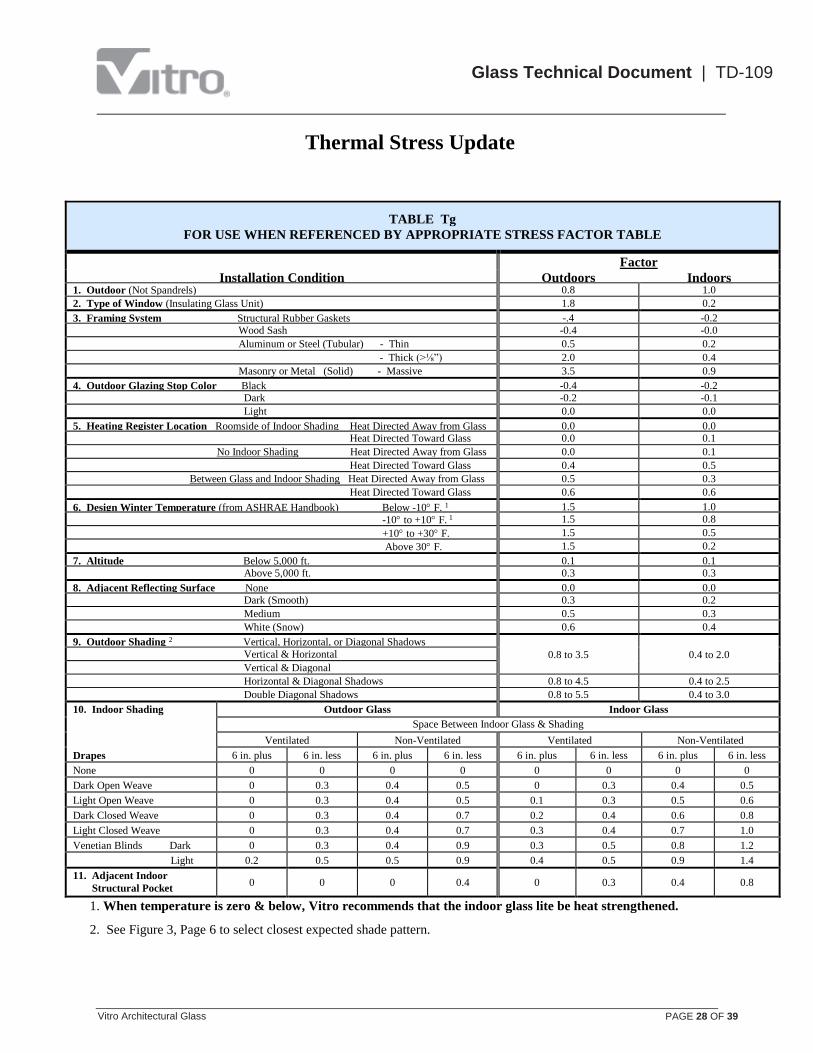
TABLE Tg
FOR USE WHEN REFERENCED BY APPROPRIATE STRESS FACTOR TABLE
Factor
Installation Condition Outdoors Indoors 1. Outdoor (Not Spandrels) 0.8 1.0
2. Type of Window (Insulating Glass Unit) 1.8 0.2
3. Framing System Structural Rubber Gaskets -.4 -0.2
Wood Sash -0.4 -0.0
Aluminum or Steel (Tubular) - Thin 0.5 0.2
- Thick (>⅛”) 2.0 0.4
Masonry or Metal (Solid) - Massive 3.5 0.9
4. Outdoor Glazing Stop Color Black -0.4 -0.2
Dark -0.2 -0.1
Light 0.0 0.0
5. Heating Register Location Roomside of Indoor Shading Heat Directed Away from Glass 0.0 0.0
Heat Directed Toward Glass 0.0 0.1
No Indoor Shading Heat Directed Away from Glass 0.0 0.1
Heat Directed Toward Glass 0.4 0.5
Between Glass and Indoor Shading Heat Directed Away from Glass 0.5 0.3
Heat Directed Toward Glass 0.6 0.6
6. Design Winter Temperature (from ASHRAE Handbook) Below -10 F. 1 1.5 1.0
-10 to +10 F. 1 1.5 0.8
+10 to +30 F. 1.5 0.5
Above 30 F. 1.5 0.2
7. Altitude Below 5,000 ft. 0.1 0.1
Above 5,000 ft. 0.3 0.3
8. Adjacent Reflecting Surface None 0.0 0.0
Dark (Smooth) 0.3 0.2
Medium 0.5 0.3
White (Snow) 0.6 0.4
9. Outdoor Shading 2 Vertical, Horizontal, or Diagonal Shadows
0.8 to 3.5 0.4 to 2.0 Vertical & Horizontal
Vertical & Diagonal
Horizontal & Diagonal Shadows 0.8 to 4.5 0.4 to 2.5
Double Diagonal Shadows 0.8 to 5.5 0.4 to 3.0
10. Indoor Shading Outdoor Glass Indoor Glass
Space Between Indoor Glass & Shading
Ventilated Non-Ventilated Ventilated Non-Ventilated
Drapes 6 in. plus 6 in. less 6 in. plus 6 in. less 6 in. plus 6 in. less 6 in. plus 6 in. less
None 0 0 0 0 0 0 0 0
Dark Open Weave 0 0.3 0.4 0.5 0 0.3 0.4 0.5
Light Open Weave 0 0.3 0.4 0.5 0.1 0.3 0.5 0.6
Dark Closed Weave 0 0.3 0.4 0.7 0.2 0.4 0.6 0.8
Light Closed Weave 0 0.3 0.4 0.7 0.3 0.4 0.7 1.0
Venetian Blinds Dark 0 0.3 0.4 0.9 0.3 0.5 0.8 1.2
Light 0.2 0.5 0.5 0.9 0.4 0.5 0.9 1.4
11. Adjacent Indoor
Structural Pocket 0 0 0 0.4 0 0.3 0.4 0.8
1. When temperature is zero & below, Vitro recommends that the indoor glass lite be heat strengthened.
2. See Figure 3, Page 6 to select closest expected shade pattern.

Thermal Stress Update
Vitro Architectural Glass PAGE 29 OF 39
Glass Technical Document | TD-109
TABLE - Th
FOR USE WHEN REFERENCED BY APPROPRIATE STRESS FACTOR TABLE
Factor
Installation Condition Outdoors Indoors 1. Outdoor (Not Spandrels) 0.8 0.8
2. Type of Window (Insulating Glass Unit) 0. 4 0.2
3. Framing System Structural Rubber Gaskets -0.2 -0.2
Wood Sash -0.1 0.0
Aluminum or Steel (Tubular) - Thin 0.0 0.3
- Thick (>⅛”) 0.8 0.6
Masonry or Metal (Solid) - Massive 1.4 1.1
4. Outdoor Glazing Stop Color Black -0.2 -0.1
Dark -0.1 0.0
Light 0.0 0.1
5. Heating Register Location Roomside of Indoor Shading Heat Directed Away from Glass 0.0 0.0
Heat Directed Toward Glass 0.1 0.1
No Indoor Shading Heat Directed Away from Glass 0.2 0.2
Heat Directed Toward Glass 0.3 0.6
Between Glass and Indoor Shading Heat Directed Away from Glass 0.4 0.4
Heat Directed Toward Glass 0.6 0.8
6. Design Winter Temperature (from ASHRAE Handbook) Below -10 F. 1 0.6 1.0
-10 to +10 F. 1 0.6 0.8
+10 to +30 F. 0.6 0.7
Above 30 F. 0.6 0.6
7. Altitude Below 5,000 ft. 0.1 0.0
Above 5,000 ft. 0.4 0.2
8. Adjacent Reflecting Surface None 0.0 0.0
Dark (Smooth) 0.3 0.2
Medium 0.5 0.3
White (Snow) 0.7 0.4
9. Outdoor Shading 2 Vertical, Horizontal, or Diagonal Shadows
0.6 to 3.0 0.4 to 2.5 Vertical & Horizontal
Vertical & Diagonal
Horizontal & Diagonal Shadows 0.6 to 3.3 0.4 to 3.0
Double Diagonal Shadows 0.6 to 3.8 0.4 to 3.5
10. Indoor Shading Outdoor Glass Indoor Glass
Space Between Indoor Glass & Shading
Ventilated Non-Ventilated Ventilated Non-Ventilated
Drapes 6 in. plus 6 in. less 6 in. plus 6 in. less 6 in. plus 6 in. less 6 in. plus 6 in. less
None 0 0 0 0 0 0 0 0
Dark Open Weave 0 0.3 0.4 0.9 0.1 0.3 0.6 0.9
Light Open Weave 0.3 0.5 0.7 1.2 0.2 0.4 0.7 1.0
Dark Closed Weave 0.3 0.6 0.9 1.7 0.3 0.4 1.0 1.4
Light Closed Weave 0.4 0.7 1.0 2.0 0.4 0.6 1.2 1.6
Venetian Blinds Dark 0.4 0.7 1.0 2.0 0.4 0.6 1.3 1.7
Light 0.5 0.9 1.1 2.0 0.6 0.8 1.5 2.0
11. Adjacent Indoor
Structural Pocket 0 0 1.0 to 1.6 1.0 to 1.6 0.6 to 0.8 0.6 to 0.8 1.0 to 2.0 1.0 to 2.0
1. When temperature is zero & below, Vitro recommends that the indoor glass lite be heat strengthened.
2. See Figure 3, Page 6 to select closest expected shade pattern.

Thermal Stress Update
Vitro Architectural Glass PAGE 30 OF 39
Glass Technical Document | TD-109
THERMAL STRESS GUIDELINES
The guidelines in Table 18 are general and have been prepared based on the assumed glazing and installation
conditions in Table 17. The assumptions used may or may not be representative of your specific project.
The guidelines presented are not a substitute for a rigorous thermal stress analysis and are offered only as a
quick, first-step evaluation tool. The actual design conditions for your project must be compared to those
assumed for the guidelines. If the assumptions used are representative or more severe than those for your
project, then the guidelines may be appropriate; if the assumptions are less severe, then a thermal stress
analysis must be done.
All of the analyses that were performed to develop the guidelines in Table 18 assumed good quality clean cut
edges. Even slightly damaged edges can significantly weaken the glass edge strength and lead to increased
thermal stress breakage.
TABLE 17
ASSUMED DESIGN AND INSTALLATION CONDITIONS
USED TO DEVELOP GLASS AREA GUIDELINES IN TABLE 18
1. FRAMING: Thin aluminum or structural rubber gaskets
2. OUTDOOR GLAZING STOP COLOR: Dark
3. HEATING REGISTERS: Indoors of the shading devices and directed away from the glass
4. DESIGN WINTER TEMPERATURE: +10 F. to + 30° F.
5. ALTITUDE: Below 5,000 feet
6. ADJACENT REFLECTING SURFACES: None
7. OUTDOOR SHADING: outdoor lite shaded 50%
8. INDOOR SHADING: 6” or more from the glass and ventilated
9. ADJACENT INDOOR STRUCTURAL POCKET: None
10. ACCEPTABLE PROBABILITY OF GLASS BREAKAGE: 8 lites/1000 lites.
11. GOOD QUALITY CLEAN CUT EDGES
12. APPLICABLE ONLY TO VISION GLASS UNITS.
Thermal Stress Update
Vitro Architectural Glass PAGE 31 OF 39
Glass Technical Document | TD-109
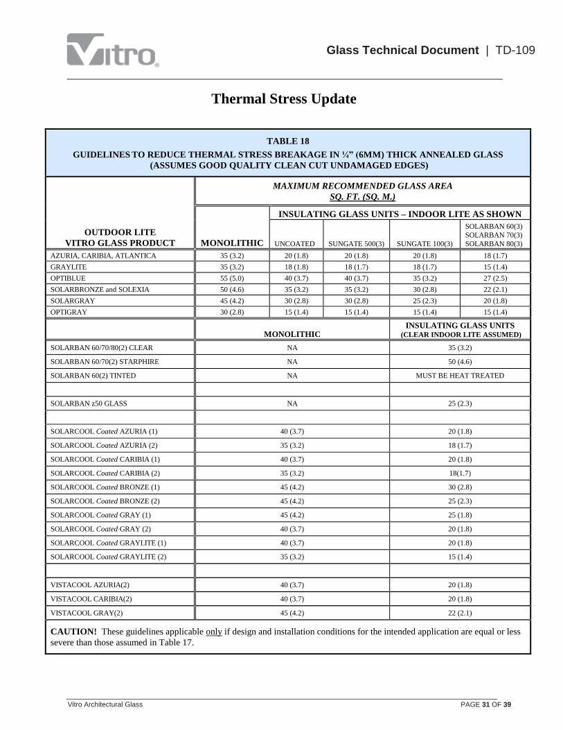
TABLE 18
GUIDELINES TO REDUCE THERMAL STRESS BREAKAGE IN ¼” (6MM) THICK ANNEALED GLASS
(ASSUMES GOOD QUALITY CLEAN CUT UNDAMAGED EDGES)
OUTDOOR LITE
VITRO GLASS PRODUCT
MAXIMUM RECOMMENDED GLASS AREA
SQ. FT. (SQ. M.)
MONOLITHIC
INSULATING GLASS UNITS – INDOOR LITE AS SHOWN
UNCOATED
SUNGATE 500(3)
SUNGATE 100(3)
SOLARBAN 60(3)
SOLARBAN 70(3)
SOLARBAN 80(3)
AZURIA, CARIBIA, ATLANTICA 35 (3.2) 20 (1.8) 20 (1.8) 20 (1.8) 18 (1.7)
GRAYLITE 35 (3.2) 18 (1.8) 18 (1.7) 18 (1.7) 15 (1.4)
OPTIBLUE 55 (5.0) 40 (3.7) 40 (3.7) 35 (3.2) 27 (2.5)
SOLARBRONZE and SOLEXIA 50 (4.6) 35 (3.2) 35 (3.2) 30 (2.8) 22 (2.1)
SOLARGRAY 45 (4.2) 30 (2.8) 30 (2.8) 25 (2.3) 20 (1.8)
OPTIGRAY 30 (2.8) 15 (1.4) 15 (1.4) 15 (1.4) 15 (1.4)
MONOLITHIC INSULATING GLASS UNITS
(CLEAR INDOOR LITE ASSUMED)
SOLARBAN 60/70/80(2) CLEAR NA 35 (3.2)
SOLARBAN 60/70(2) STARPHIRE NA 50 (4.6)
SOLARBAN 60(2) TINTED NA MUST BE HEAT TREATED
SOLARBAN z50 GLASS NA 25 (2.3)
SOLARCOOL Coated AZURIA (1) 40 (3.7) 20 (1.8)
SOLARCOOL Coated AZURIA (2) 35 (3.2) 18 (1.7)
SOLARCOOL Coated CARIBIA (1) 40 (3.7) 20 (1.8)
SOLARCOOL Coated CARIBIA (2) 35 (3.2) 18(1.7)
SOLARCOOL Coated BRONZE (1) 45 (4.2) 30 (2.8)
SOLARCOOL Coated BRONZE (2) 45 (4.2) 25 (2.3)
SOLARCOOL Coated GRAY (1) 45 (4.2) 25 (1.8)
SOLARCOOL Coated GRAY (2) 40 (3.7) 20 (1.8)
SOLARCOOL Coated GRAYLITE (1) 40 (3.7) 20 (1.8)
SOLARCOOL Coated GRAYLITE (2) 35 (3.2) 15 (1.4)
VISTACOOL AZURIA(2) 40 (3.7) 20 (1.8)
VISTACOOL CARIBIA(2) 40 (3.7) 20 (1.8)
VISTACOOL GRAY(2) 45 (4.2) 22 (2.1)
CAUTION! These guidelines applicable only if design and installation conditions for the intended application are equal or less
severe than those assumed in Table 17.
Thermal Stress Update
Vitro Architectural Glass PAGE 32 OF 39
Glass Technical Document | TD-109
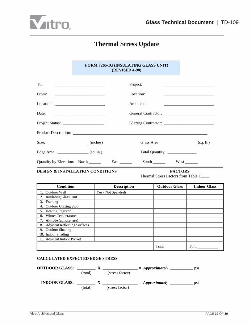
FORM 7265-IG (INSULATING GLASS UNIT)
(REVISED 4-98)
To: ________________________ Project: ________________________
From: ________________________ Location: ________________________
Location: ________________________ Architect: ________________________
Date: ________________________ General Contractor: ________________________
Project Status: ____________________ Glazing Contractor: ________________________
Product Description: _________________________________________________________________
Size: ____________________ (inches) Glass Area: _________________ (sq. ft.)
Edge Area: _______________ (sq. in.) Total Quantity: ______________
Quantity by Elevation: North ______ East ______ South ______ West ______
DESIGN & INSTALLATION CONDITIONS FACTORS
Thermal Stress Factors from Table T____
Condition Description Outdoor Glass Indoor Glass
1. Outdoor Wall Yes - Not Spandrels
2. Insulating Glass Unit
3. Framing
4. Outdoor Glazing Stop
5. Heating Register
6. Winter Temperature
7. Altitude (atmosphere)
8. Adjacent Reflecting Surfaces
9. Outdoor Shading
10. Indoor Shading
11. Adjacent Indoor Pocket
Total
_________
Total__________
CALCULATED EXPECTED EDGE STRESS
OUTDOOR GLASS: _________ X _________________ = Approximately ___________ psi
(total) (stress factor)
INDOOR GLASS: _________ X _________________ = Approximately ___________ psi
(total) (stress factor)

Thermal Stress Update
Vitro Architectural Glass PAGE 33 OF 39
Glass Technical Document | TD-109
TABLE 19
(FOR USE WITH FORM 7265-M)
Condition Factor 1. Outdoor (Not Spandrels) 1.0
2. Type of Application
Single glazed 0.0
Double (including storm sash, not sealed insulating glass unit) 0.8
3. Framing System
Structural lockstrip gaskets -0.1
Wood 0.1
Aluminum or Steel 0.2
Concrete 1.0
4. Outdoor Glazing Stop Color
Black -0.2
Dark -0.1
Light 0.0
5. Heating Register Location
Room side of indoor shading; no indoor shading
Heat directed away from glass 0.0
Heat directed toward glass 0.2
Between glass and indoor shading
Heat directed away from glass 0.2
Heat directed toward glass 0.3
6. Design Winter Temperature (from ASHRAE Handbook)
Below 0 F. 0.0
From 0 F. to 40 F. -0.1
Above 40 F. -0.2
7. Altitude
Below 5,000 feet 0.0
Above 5,000 feet 0.1
8. Adjacent Reflecting Surface
None 0.0
Dark 0.2
Medium 0.3
White (Snow) 0.4
9. Outdoor Shading1
Vertical, Horizontal, or Diagonal Shadows 0.0 to 1.0
Vertical & Horizontal 0.3 to 1.0
Vertical & Diagonal 0.0 to 1.5
Horizontal & Diagonal 0.2 to 1.2
Double Diagonal 0.0 to 2.3
10. Indoor Shading
Space Between Glass & Shading
Ventilated Non-Ventilated
6 in. plus 6 in. less 6 in. plus 6 in. less
None 0.0 0.0 0.0 0.0
Dark open-weave drapes 0.1 0.2 0.4 0.5
Light open-weave drapes 0.2 0.3 0.5 0.6
Dark closed-weave drapes 0.2 0.3 0.5 0.6
Light closed-weave drapes 0.3 0.4 0.6 0.7
Dark venetian blinds 0.3 0.4 0.6 0.7
Light venetian blinds 0.4 0.5 0.7 0.8
11. Adjacent Indoor Structural Pocket
1. See Figure 4, Page 6 to select closest expected shade pattern.

Thermal Stress Update
Vitro Architectural Glass PAGE 34 OF 39
Glass Technical Document | TD-109
FORM 7265-M (MONOLITHIC GLASS)
(REVISED 4-98)
To: ________________________ Project: ________________________
From: ________________________ Location: ________________________
Location: ________________________ Architect: ________________________
Date: ________________________ General Contractor: ________________________
Project Status: ____________________ Glazing Contractor: ________________________
Glass Thickness & Type: _____________________________________________________________
Size: ____________________ (inches) Glass Area: _________________ (sq. ft.)
Edge Area: _______________ (sq. in.) Total Quantity: ______________
Quantity by Elevation: North ______ East ______ South ______ West ______
DESIGN & INSTALLATION CONDITIONS
Condition Description
Thermal Stress Factors
From Table 19
1. Outdoor Wall Yes - Not Spandrels 1.0
2. Framing
3. Outdoor Glazing Stop
4. Heating Register
5. Winter Temperature
6. Altitude (atmosphere)
7. Adjacent Reflecting Surfaces
8. Outdoor Shading
9. Indoor Shading
10. Adjacent Indoor Structural Pocket
Total _________
CALCULATED EXPECTED EDGE STRESS
OUTDOOR GLASS: _________ X ____________ = Approximately ___________ psi
(total) (stress factor)
Thermal Stress Update
Vitro Architectural Glass PAGE 35 OF 39
Glass Technical Document | TD-109
How to Use Vitro’s Thermal Stress Analysis Procedure
1. Early in the project design stage, review project architectural and shop drawings focusing on plan,
elevations and sections through elevations. Note compass orientation of the project elevations:
Windows facing between N 60° and N 45° E (non-sunny elevations in the Northern hemisphere) will
most likely require normal glazing practice. All other orientations require detailed thermal stress
analysis to determine the recommended glass types to reduce thermal stress breakage to acceptable
levels.
2. With the appropriate information in hand, including this document, consult with the responsible project
architect or decision maker for assistance in choosing the installation and design condition factors
required to complete the thermal stress analysis.
3. Complete Form 7265-IG or 7265-M in detail, including project description, glass thickness and type,
quantities and sizes and by referencing the appropriate Charts and Tables in this document to complete
each of the required “Installation/Design Conditions” and to select the corresponding Factors.
Note: For Solarcool coated glass, whether monolithic or in insulating units, it is important to
correctly identify the coating surface location and then use the appropriate factors from the
tables. This is also true for Solarban and Sungate coated glass that, except for Sungate 500 coated
glass, are always used in insulating glass units, never as monolithic glass.
4. Calculate the expected thermal stress (for both the INDOOR and OUTDOOR glass in an insulating glass
unit) and use Chart 1 or Chart 2 to determine the glass fabrication requirement.
Note: If you wish, Vitro will be pleased to calculate the expected in-service thermal stress and
provide the recommended glass type based on your completed Form 7265. Send the completed
7265-IG or 7265-M form to:
Vitro Architectural Glass
Technical Services
Performance Glazings
400 Guys Run Road
Cheswick, PA 15024
On-Line Thermal Stress Analysis Tool
A Thermal Stress Analysis computer program, based on the procedures included in this document, is
available on Vitro’s website. The program allows users to either select default design conditions, or to
specify appropriate design conditions for their specific project. The program will then perform the analysis
and display the recommended glass treatment. In addition, the program will display the calculated
probability of glass breakage for both the outdoor and indoor glass lites for both annealed and heat
strengthened glass. The program may be accessed via the following link:
Thermal Stress Analysis

Thermal Stress Update
Vitro Architectural Glass PAGE 36 OF 39
Glass Technical Document | TD-109
Thermal Stress Completed Example
For this example, let’s consider the following product properties:
A 1” Insulating Glass Unit (1/4” GRAYLITE + 1/2” Airspace + 1/4” Clear)
Size - 48” x 72”
The completed Form 7265-IG on the following page was prepared as follows:
1. Refer to Table 5 “Stress Factors for Clear and Tinted Insulating Glass Units” to determine the
appropriate STRESS FACTORS and Table to use to determine the DESIGN FACTORS.
As shown in Table 5, the Stress Factors for GRAYLITE are 920 (South, East, and West
elevations and 430 for the North elevation. Table Tf is indicated for determining the
Design Factors.
The Stress Factors for the Clear INDOOR lite are 220 (South, East, and West and 110 for
the North elevation.
2. Calculate the Glass Edge Area by multiplying the 2 x (width + height) x thickness (in inches).
For the completed example this would be 2 x (48 + 72) x 0.25 = 60 square inches.
3. Using Table Tf, choose the appropriate Design Factors for each Installation Condition.
In the completed example, the assumed Framing system was Tubular Aluminum or Steel -
Thin and from Table Tf the associated Design Factors for both the Outdoor and Indoor
Glass Lite are 0.0.
Note that for Installation Condition 9 “Outdoor Shading”, you must refer to Figure 3 on
Page 6 to help determine the appropriate shading pattern nomenclature and apply that to the
appropriate table (Tf, Tg, Th) to determine the Design Factor. In the completed example,
Horizontal Outdoor Shading was assumed with 50% shade coverage. Interpolating between
the 75% shade coverage factor of 0.4 and the 25% shade factor of 2.3 for the outdoor lite
yields a factor of 1.4. The same procedure applies for the indoor lite.
4. Arithmetically sum all of the factors for the outdoor and indoor glass lites.
5. Calculate the estimated thermal stress for each lite by multiplying the appropriate design factor
total by the stress factor.
6. Determine the recommended glass treatment for each glass lite by using Chart 1.
Project lines from the calculated edge area (horizontal axis) and from the estimated thermal
stress (vertical axis) until they intersect.
If the intersection point is on or above the curve, then the glass must be heat strengthened; if
the intersection point is below the curve, annealed glass is adequate to meet the estimated
thermal stress based on the assumed design conditions.
NOTES:
a) Heat strengthened or Tempered glass may still be required to meet safety, wind load, or other
design considerations.
b) Careful consideration should be given to heat strengthening the glass if the analysis reveals
that the estimated thermal stress is approaching the limits of adequate performance for
annealed glass.
c) This example considers the non-North facing elevations, which are more severe for thermal
stress than the North elevation. A similar analysis can obviously be done for the North
elevation

Thermal Stress Update
Vitro Architectural Glass PAGE 37 OF 39
Glass Technical Document | TD-109
EXAMPLE
COMPLETED FORM 7265-IG
To: Mr. Good Customer Project: Test Case
From: Reliable Supplier Location: Anywhere, USA
Location: Somewhere, USA Architect: Creative Designs
Date: 3 June 1998 General Contractor:Big Builders
Glazing Contractor: ABC Glass
Project Status: Design
Product Description: 1” Graylite IG Unit
Size: 48” x 72” (inches) Glass Area: 24.0 sq. ft.
Edge Area: 60 (sq. in.) Total Quantity: 350
Quantity by Elevation: North 50 East 75 South 150 West 75
DESIGN & INSTALLATION CONDITIONS FACTORS
Thermal Stress Factors From Table Tf
Condition Description Outdoor Glass Indoor Glass
1. Outdoor Wall Yes - Not Spandrels 0.8 1.0
2. Insulating Glass Unit With 1/2” Airspace 0.2 1.4
3. Framing Tubular Aluminum or Steel - Thin 0.0 0.0
4. Outdoor Glazing Stop Black -0.2 -0.2
5. Heating Register Roomside - Directed Away from Glass 0.0 0.0
6. Winter Temperature +10 to +30 degrees F. 0.5 3.0
7. Altitude (atmosphere) Above 5,000 ft. 0.3 0.5
8. Adjacent Reflecting Surfaces Medium 0.3 0.4
9. Outdoor Shading Horizontal - 50% Shade Coverage 1.4 1.3
10. Indoor Shading Dark Open Weave, Ventilated, 6 in. Plus 0.0 0.2
11. Adjacent Indoor Pocket No 0.0 0.0
Total 3.3 Total 7.6
CALCULATED EXPECTED EDGE STRESS
OUTDOOR GLASS: 3.3 X 920 = Approximately 3,036 psi
(total) (stress factor)
INDOOR GLASS: 7.6 X 220 = Approximately 1,672 psi
(total) (stress factor)
Based on the analysis, the calculated edge stress of the outdoor glass, when plotted on Chart 1, requires that the
outdoor glass be heat strengthened. Similarly, the indoor glass can be annealed for thermal stress purposes.

Thermal Stress Update
Vitro Architectural Glass PAGE 38 OF 39
Glass Technical Document | TD-109
CHART 1 – INSULATING GLASS UNITS
CHART 2 – MONOLITHIC GLASS
Thermal Stress Update
Vitro Architectural Glass PAGE 39 OF 39
Glass Technical Document | TD-109
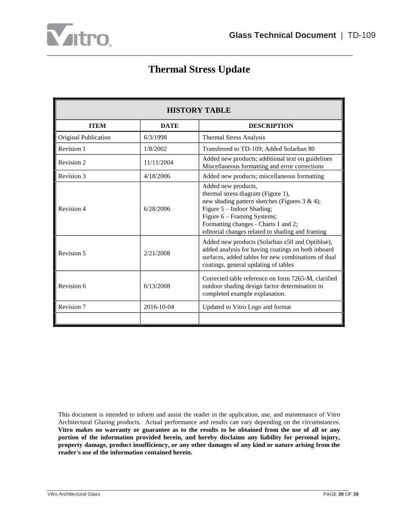
HISTORY TABLE
ITEM DATE DESCRIPTION
Original Publication 6/3/1998 Thermal Stress Analysis
Revision 1 1/8/2002 Transferred to TD-109; Added Solarban 80
Revision 2 11/11/2004 Added new products; additional text on guidelines
Miscellaneous formatting and error corrections
Revision 3 4/18/2006 Added new products; miscellaneous formatting
Revision 4 6/28/2006
Added new products,
thermal stress diagram (Figure 1),
new shading pattern sketches (Figures 3 & 4);
Figure 5 – Indoor Shading;
Figure 6 – Framing Systems;
Formatting changes - Charts 1 and 2;
editorial changes related to shading and framing
Revision 5 2/21/2008
Added new products (Solarban z50 and Optiblue),
added analysis for having coatings on both inboard
surfaces, added tables for new combinations of dual
coatings, general updating of tables
Revision 6 6/13/2008
Corrected table reference on form 7265-M, clarified
outdoor shading design factor determination in
completed example explanation.
Revision 7 2016-10-04 Updated to Vitro Logo and format
This document is intended to inform and assist the reader in the application, use, and maintenance of Vitro
Architectural Glazing products. Actual performance and results can vary depending on the circumstances.
Vitro makes no warranty or guarantee as to the results to be obtained from the use of all or any
portion of the information provided herein, and hereby disclaims any liability for personal injury,
property damage, product insufficiency, or any other damages of any kind or nature arising from the
reader's use of the information contained herein.