
Thermal Solutions Communications Gateway Instruction...
38
Thermal Solutions Communications Gateway Instruction Manual Part Number 104568-01 Revised: January 1, 2014 Contents 1. Introduction 2 2. ProtoNode Setup 3 3. Wiring 7 4. Commissioning 13 5. Field Validating 18 Appendix A. Trouble Shooting 20 B. ABC Boiler Points List 24 C. TSBC Boiler Points List 28 D. Specifications 32 E. Address DIP Switch Settings 33 Application The Thermal Solutions Communications Gateway (Gateway) interfaces Energy Management Systems (EMS) to the Apex Boiler Control (ABC) or Thermal Solutions Boiler Control (TSBC) found on Thermal Solutions Boilers. The gateways options provide monitoring, remote setpoint and burner on/off control using BACnet MS/TP, BACnet/IP, N2, Modbus TCP or LonWorks protocols. Intent This document provides the necessary information to facilitate Gateway installation. This Instruction Manual includes practical, installation and setup-detailed information. The intended users are contractors and factory support personnel. ProtoNode RER ProtoNode LER
Transcript of Thermal Solutions Communications Gateway Instruction...

Thermal Solutions Communications
Gateway Instruction Manual
Part Number 104568-01 Revised: January 1, 2014
Contents 1. Introduction 2 2. ProtoNode Setup 3 3. Wiring 7 4. Commissioning 13 5. Field Validating 18 Appendix A. Trouble Shooting 20 B. ABC Boiler Points List 24 C. TSBC Boiler Points List 28 D. Specifications 32 E. Address DIP Switch Settings 33
Application The Thermal Solutions Communications Gateway (Gateway) interfaces Energy Management Systems (EMS) to the Apex Boiler Control (ABC) or Thermal Solutions Boiler Control (TSBC) found on Thermal Solutions Boilers. The gateways options provide monitoring, remote setpoint and burner on/off control using BACnet MS/TP, BACnet/IP, N2, Modbus TCP or LonWorks protocols. Intent This document provides the necessary information to facilitate Gateway installation. This Instruction Manual includes practical, installation and setup-detailed information. The intended users are contractors and factory support personnel.
ProtoNode RER ProtoNode LER
Thermal Solutions Communication Gateway Instruction Manual
Page 2 of 38 Part Number 104568-01
1 INTRODUCTION
Thermal Solutions Communications Gateway (Gateway) is an external, high performance Energy Management System (EMS) multi-protocol gateway that uses the Field Server ProtoNode Technology. The Gateway can support multiple Boilers. It has been pre-programmed to Auto-Discover any Apex Boiler Control (ABC) or Thermal Solutions Boiler Control (TSBC) equipped boilers connected to the Gateway and automatically configures them for BACnet®1MS/TP, BACnet/IP, Metasys®2 N2 by JCI, Modbus TCP or LonWorks®3. It is not necessary to download any configuration files to support the required applications.
1.1 BTL Mark – BACnet Testing Laboratory
1.2 LonMark Certification
1 BACnet is a registered trademark of ASHRAE 2 Metasys is a registered trademark of Johnson Controls Inc. 3LonWorks is a registered trademark of Echelon Corporation
The BTL Mark on the Gateway is a symbol that indicates to a consumer that a product has passed a series of rigorous tests conducted by an independent laboratory which verifies that the product correctly implements the BACnet features claimed in the listing. The mark is a symbol of a high-quality BACnet product. Go to http://www.bacnetinternational.net/btl/ for more information about the BACnet Testing Laboratory.
LonMark International is the recognized authority for certification, education, and promotion of interoperability standards for the benefit of manufacturers, integrators and end users. LonMark International has developed extensive product certification standards and tests to provide the integrator and user with confidence that products from multiple manufacturers utilizing LonMark devices work together.
Thermal Solutions Communication Gateway Instruction Manual
Page 3 of 38 Part Number 104568-01
2 PROTONODE SETUP
The following steps need to be performed during installation:
2.1 Set Boiler “Boiler Address”
On ABC equipped boiler from the boiler mounted display, set a unique “Sequencer Slave” or Boiler Address for each boiler that will be connected to the network. On TSBC equipped boiler from the communication menu set the following: Protocol = “Modbus” Modbus Address = between (1 and 20) Baud Rate = 38.4kbps Parity = none Refer to the Boiler’s instruction manual for password and menu navigation instructions.
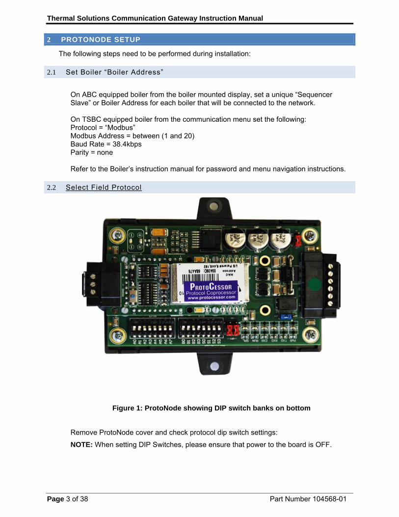
2.2 Select Field Protocol
Figure 1: ProtoNode showing DIP switch banks on bottom
Remove ProtoNode cover and check protocol dip switch settings:
NOTE: When setting DIP Switches, please ensure that power to the board is OFF.

Thermal Solutions Communication Gateway Instruction Manual
Page 4 of 38 Part Number 104568-01
- The “S0 – S2” bank of DIP switches on the ProtoNode RER are used to select the various field protocols (BACnet MS/TP). See the chart below for the DIP switch settings.
- The “S0 – S2” bank of DIP switches on the ProtoNode LER are disabled.
Figure 2: S0 – S3 DIP Switches “shown off position”
ProtoNode RER – FPC-N34-103-126-0731
Field Protocol Settings
S0 – S2 DIP Switches S0 S1 S2 BACnet MSTP/BACnet IP Off Off Off Metasys N2 Open On Off Off Modbus TCP Off On Off
2.3 Auto-Discover and Automatically Load Configuration File
The following chart describes “S3” DIP Switch setting for Enabling Auto-Discovering of known devices attached to the ProtoNode RER or LER.
- Set “S3” DIP switch to “On” position to Auto-Discover Boilers attached to the ProtoNode. It will take 3 minutes to discover all Modbus RTU devices attached to the ProtoNode.
- Once the ProtoNode has discovered all of the Modbus RTU devices, set the S3 DIP switch to the OFF position to save the recently built configuration.
ProtoNode RER and LER S3 DIP Switch Auto-Discovery Mode S3 Auto-Discovery ON – Build New Configuration On Auto-Discover OFF – Load Current Configuration Off
NOTE
Initial Auto Discovery Cycle
All boilers MUST be powered and connected to the ProtoNode before cycling power to the ProtoNode. The ProtoNode will auto discover only connected boilers. If a boiler is connected after the ProtoNode has completed auto discovery it will not “find” the new boiler.
Thermal Solutions Communication Gateway Instruction Manual
Page 5 of 38 Part Number 104568-01
2.4 BACnet MS/TP Setup (skip if this protocol is not used by the EMS)
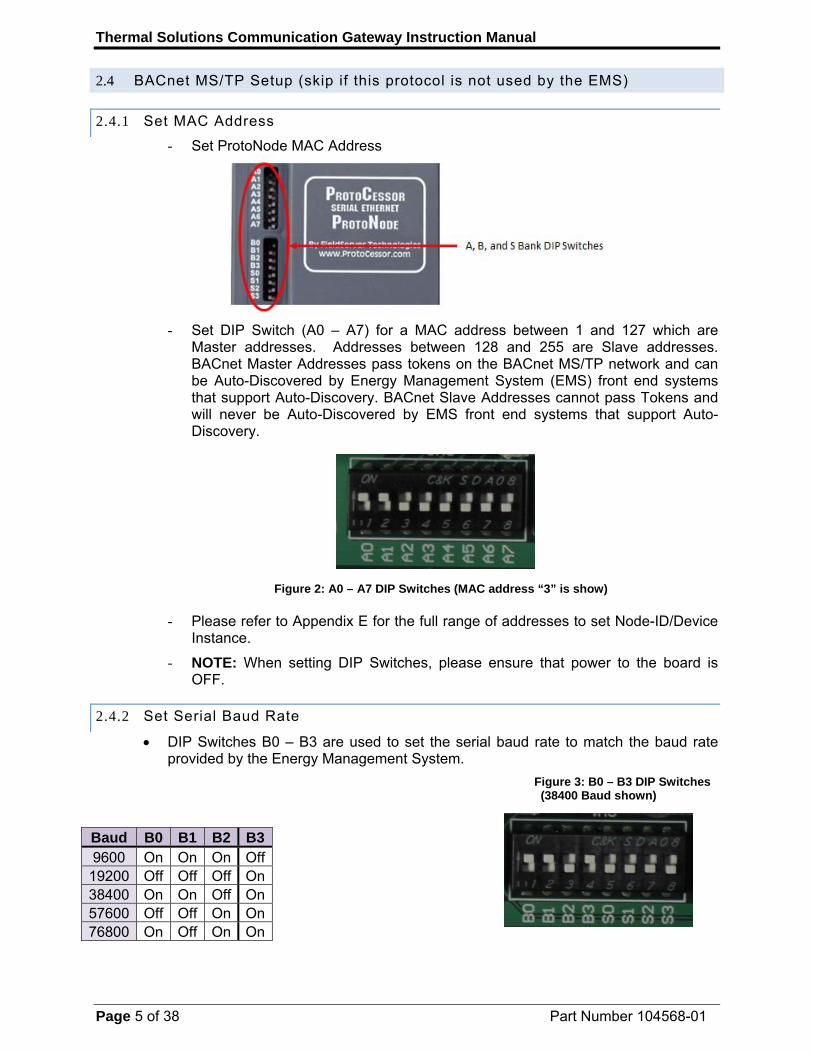
2.4.1 Set MAC Address
- Set ProtoNode MAC Address
- Set DIP Switch (A0 – A7) for a MAC address between 1 and 127 which are
Master addresses. Addresses between 128 and 255 are Slave addresses. BACnet Master Addresses pass tokens on the BACnet MS/TP network and can be Auto-Discovered by Energy Management System (EMS) front end systems that support Auto-Discovery. BACnet Slave Addresses cannot pass Tokens and will never be Auto-Discovered by EMS front end systems that support Auto-Discovery.
Figure 2: A0 – A7 DIP Switches (MAC address “3” is show)
- Please refer to Appendix E for the full range of addresses to set Node-ID/Device Instance.
- NOTE: When setting DIP Switches, please ensure that power to the board is OFF.
2.4.2 Set Serial Baud Rate
DIP Switches B0 – B3 are used to set the serial baud rate to match the baud rate provided by the Energy Management System.
Figure 3: B0 – B3 DIP Switches (38400 Baud shown)
Baud B0 B1 B2 B3 9600 On On On Off
19200 Off Off Off On 38400 On On Off On 57600 Off Off On On 76800 On Off On On

Thermal Solutions Communication Gateway Instruction Manual
Page 6 of 38 Part Number 104568-01
2.5 BACnet IP Setup (skip if this protocol is not used by the EMS)
Set Node-ID Instance Setting - The BACnet device instances will be set by the node offset + the Boiler’s Boiler
Address (Modbus RTU device) address. o The Node Offset is currently set to 50,000 in the configuration file so
Modbus address 1 would be assigned a device instance of 50001. o If the 2nd Device Modbus address is set to 2 then the device instance will
be set to 50002. o To change the node_offset (Section 4.3). The node offset can be
changed from 50000 to 1 to 4,194,302 via the Web Configurator. o The BACnet Device Instance can range from 1 to 4,194,303.
2.6 Metasys N2 & Modbus TCP/IP Setup (skip if this protocol is not used by the EMS)
Metasys N2 & Modbus TCP/IP Device Address Setting
- The device addresses will be the same as the discovered Boilers’ Boiler Address (Modbus RTU devices) (1 through 8).
2.7 Commission the ProtoNode on the LonWorks Network.
This needs to be done by the LonWorks administrator using a LonWorks Commissioning tool. (See Section 4)
2.8 If the Field protocol is BACnet/IP or Modbus TCP set IP Address.
Run the ProtoNode web GUI utility program to change the IP address. No changes to the configuration file are necessary. (See Section 4)
Thermal Solutions Communication Gateway Instruction Manual
Page 7 of 38 Part Number 104568-01
3 WIRING
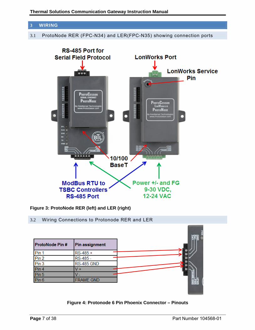
3.1 ProtoNode RER (FPC-N34) and LER(FPC-N35) showing connection ports
Figure 3: ProtoNode RER (left) and LER (right)
3.2 Wiring Connections to Protonode RER and LER
Figure 4: Protonode 6 Pin Phoenix Connector – Pinouts

Thermal Solutions Communication Gateway Instruction Manual
Page 8 of 38 Part Number 104568-01
0000 Figure 5: Connecting the TSBC Control to the ProtoNode’s RS-485
Phone cable signals (4 wire)
1 A (+) Black 2 B (-) Red 3 B (-) Green 4 A (+) Yellow Phone cable signals (6 wire).
1 no connection 2 A (+) Black 3 B (-) Red 4 B (-) Green 5 A (+) Yellow 6 no connection
Connect TSBC’s RJ11 A (+) Black (RS485+) to Protonode’s Pin 1 (RS485+) on the Phoenix 6 pin connector.
Connect TSBC’s RJ11 B (-) Red (RS485-) to Protonode’s Pin 2 (RS485-) on the Phoenix 6 pin connector.
Ground between TSBC and the Protonode does not need to be connected
Thermal Solutions Communication Gateway Instruction Manual
Page 9 of 38 Part Number 104568-01
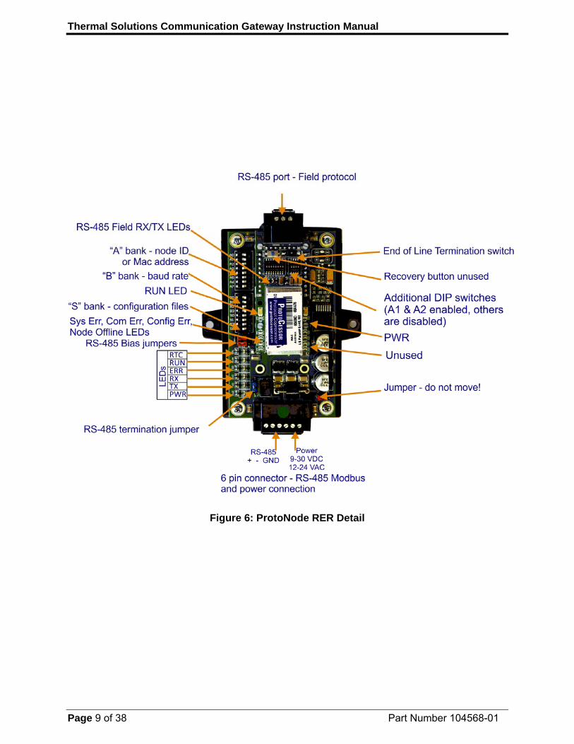
Figure 6: ProtoNode RER Detail

Thermal Solutions Communication Gateway Instruction Manual
Page 10 of 38 Part Number 104568-01
Figure 7: ProtoNode LER Detail
Thermal Solutions Communication Gateway Instruction Manual
Page 11 of 38 Part Number 104568-01
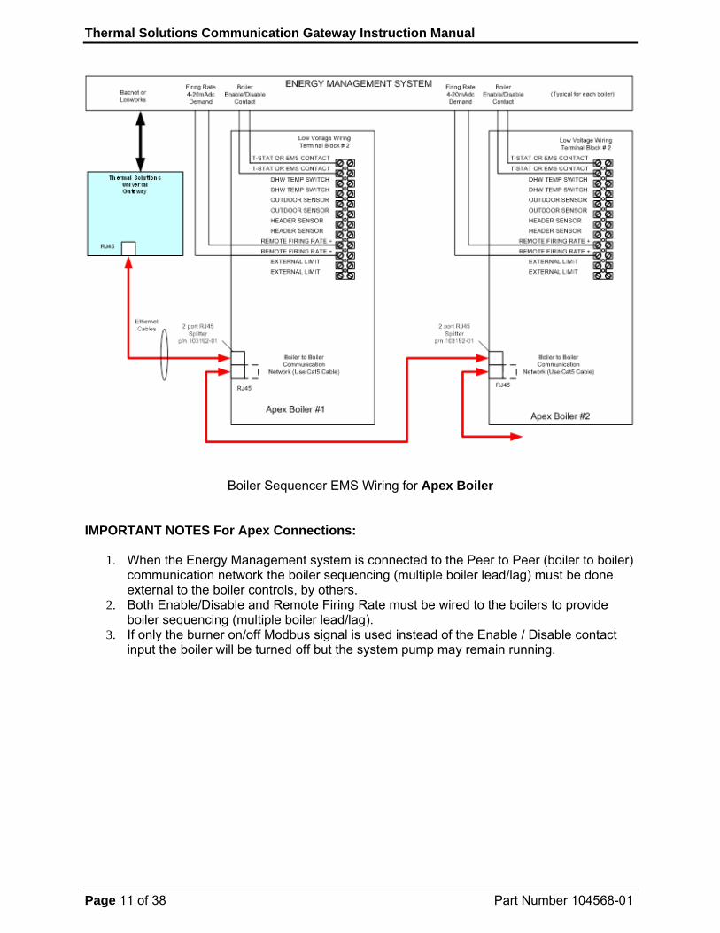
Boiler Sequencer EMS Wiring for Apex Boiler IMPORTANT NOTES For Apex Connections:
1. When the Energy Management system is connected to the Peer to Peer (boiler to boiler) communication network the boiler sequencing (multiple boiler lead/lag) must be done external to the boiler controls, by others.
2. Both Enable/Disable and Remote Firing Rate must be wired to the boilers to provide boiler sequencing (multiple boiler lead/lag).
3. If only the burner on/off Modbus signal is used instead of the Enable / Disable contact input the boiler will be turned off but the system pump may remain running.
Thermal Solutions Communication Gateway Instruction Manual
Page 12 of 38 Part Number 104568-01
ENERGY MANAGEMENT SYSTEM
TSBCControl System
Thermal SolutionsUniversalGateway
Bacnet or Lonworks
RJ11
Local /RemoteContact
(OPTIONAL)
(Typical for each boiler)
Ethernet Cables
Local /RemoteContact
(OPTIONAL)
RJ11
Connects to Up to 8 Boilers
Boiler 1
RJ11
2 port RJ11 Splitter
(Not Included)
TSBCControl System
Boiler 2
LR
C
LR
C
2 port RJ11 Splitter
(Not Included)
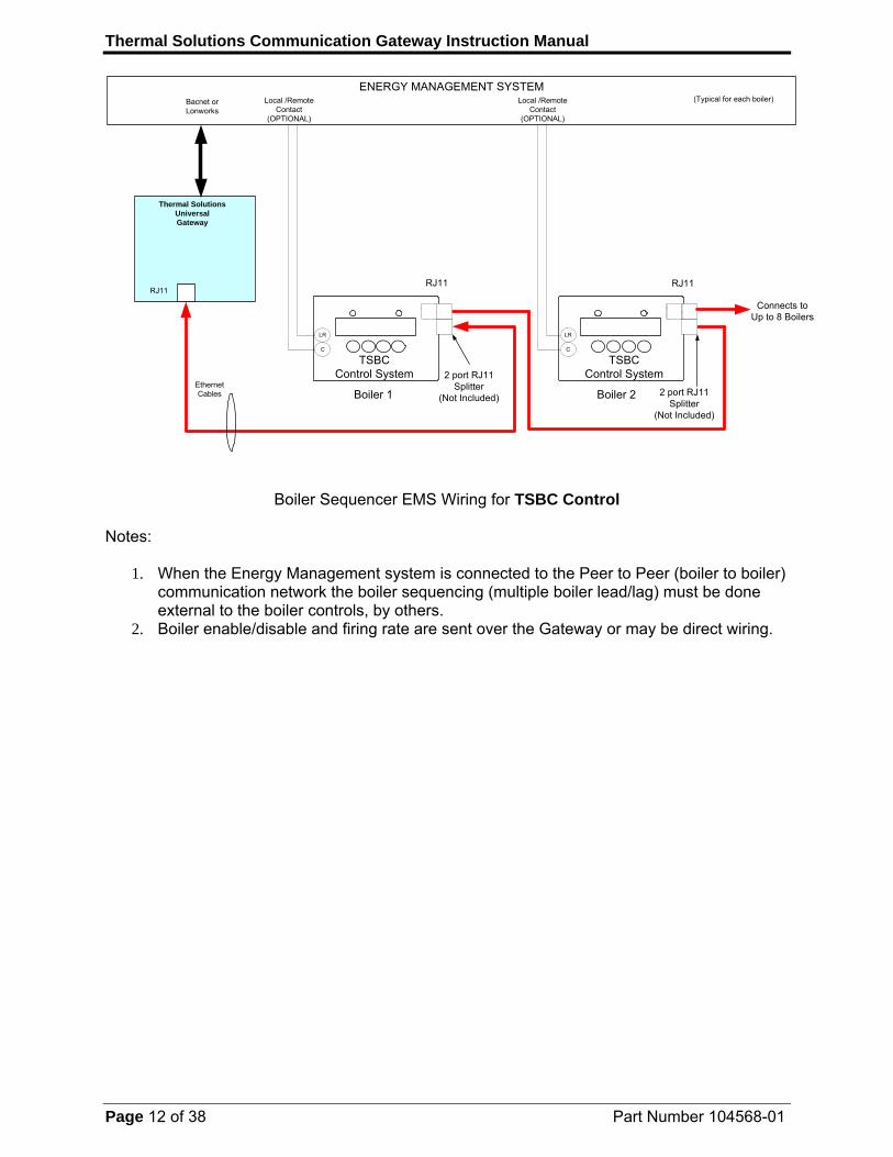
Boiler Sequencer EMS Wiring for TSBC Control Notes:
1. When the Energy Management system is connected to the Peer to Peer (boiler to boiler) communication network the boiler sequencing (multiple boiler lead/lag) must be done external to the boiler controls, by others.
2. Boiler enable/disable and firing rate are sent over the Gateway or may be direct wiring.
Thermal Solutions Communication Gateway Instruction Manual
Page 13 of 38 Part Number 104568-01
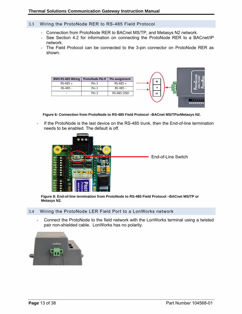
3.3 Wiring the ProtoNode RER to RS-485 Field Protocol
- Connection from ProtoNode RER to BACnet MS/TP, and Metasys N2 network. - See Section 4.2 for information on connecting the ProtoNode RER to a BACnet/IP
network. - The Field Protocol can be connected to the 3-pin connector on ProtoNode RER as
shown.
Figure 6: Connection from ProtoNode to RS-485 Field Protocol –BACnet MS/TPorMetasys N2.
- If the ProtoNode is the last device on the RS-485 trunk, then the End-of-line termination needs to be enabled. The default is off.
Figure 8: End-of-line termination from ProtoNode to RS-485 Field Protocol –BACnet MS/TP or Metasys N2.
3.4 Wiring the ProtoNode LER Field Port to a LonWorks network
- Connect the ProtoNode to the field network with the LonWorks terminal using a twisted pair non-shielded cable. LonWorks has no polarity.
End-of-Line Switch

Thermal Solutions Communication Gateway Instruction Manual
Page 14 of 38 Part Number 104568-01
4 COMMISSIONING
4.1 Commissioning the ProtoNode LER on a LonWorks network
Commissioning may only be performed by the LonWorks administrator. To commission the ProtoNode LER LonWorks port, insert a small screwdriver in the commissioning hole on the face of the LER’s enclosure to access the Service Pin. See the illustration on the ProtoNode LER as to which way to toggle the screw driver during commissioning.
If an XIF file is required, see steps Section 4.1.1 to generate XIF
4.1.1 Instructions to Upload XIF File From the ProtoNode LER Using FS GUI Web Server
Connect a standard cat5 Ethernet cable between the PC and ProtoNode
The Default IP Address of the ProtoNode is 192.168.1.24, Subnet Mask is 255.255.255.0. If the PC and the ProtoNode are on different IP Networks, assign a static IP Address to the PC on the 192.168.1.xxx network
For Windows XP:
Go to > >
Right-click on Local Area Connection > Properties
Highlight >
For Windows 7:
Go to > >
> >
Right-click on Local Area Connection > Properties
Highlight >
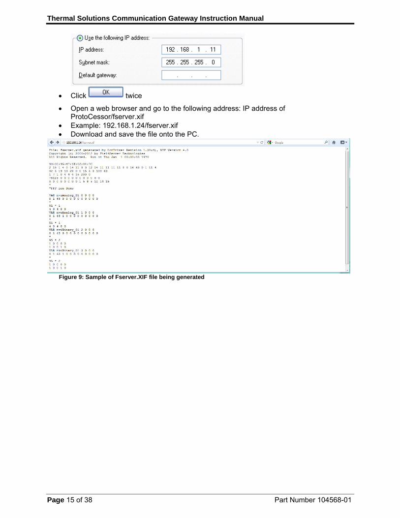
For Windows XP and Windows 7, select: Use the following IP address
Thermal Solutions Communication Gateway Instruction Manual
Page 15 of 38 Part Number 104568-01
Click twice
Open a web browser and go to the following address: IP address of ProtoCessor/fserver.xif
Example: 192.168.1.24/fserver.xif Download and save the file onto the PC.
Figure 9: Sample of Fserver.XIF file being generated
Thermal Solutions Communication Gateway Instruction Manual
Page 16 of 38 Part Number 104568-01
4.2 Commissioning BACnet/IP and Modbus TCP/IP address
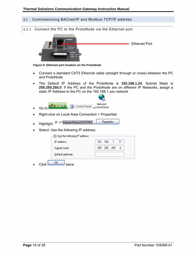
4.2.1 Connect the PC to the ProtoNode via the Ethernet port
Figure 9: Ethernet port location on the ProtoNode
Connect a standard CAT5 Ethernet cable (straight through or cross) between the PC
and ProtoNode
The Default IP Address of the ProtoNode is 192.168.1.24, Subnet Mask is 255.255.255.0. If the PC and the ProtoNode are on different IP Networks, assign a static IP Address to the PC on the 192.168.1.xxx network
Go to > >
Right-click on Local Area Connection > Properties
Highlight >
Select: Use the following IP address
Click twice
Ethernet Port
Thermal Solutions Communication Gateway Instruction Manual
Page 17 of 38 Part Number 104568-01
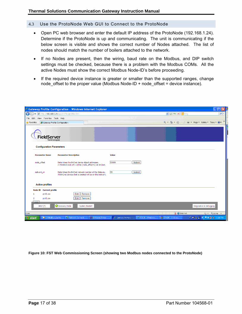
4.3 Use the ProtoNode Web GUI to Connect to the ProtoNode
Open PC web browser and enter the default IP address of the ProtoNode (192.168.1.24). Determine if the ProtoNode is up and communicating. The unit is communicating if the below screen is visible and shows the correct number of Nodes attached. The list of nodes should match the number of boilers attached to the network.
If no Nodes are present, then the wiring, baud rate on the Modbus, and DIP switch settings must be checked, because there is a problem with the Modbus COMs. All the active Nodes must show the correct Modbus Node-ID’s before proceeding.
If the required device instance is greater or smaller than the supported ranges, change node_offset to the proper value (Modbus Node-ID + node_offset = device instance).
Figure 10: FST Web Commissioning Screen (showing two Modbus nodes connected to the ProtoNode)

Thermal Solutions Communication Gateway Instruction Manual
Page 18 of 38 Part Number 104568-01
4.4 Set IP Address for BACnet/IP and Modbus TCP
When it is necessary to set the BACnet/IP or Modbus TCP ID the following procedure could be followed. Note this is the responsibility of the Energy Management System Administrator.
- Open a PC web browser, enter the default IP address of the ProtoNode (192.168.1.24) and connect to the ProtoNode.
- From the Field Server main home page, click the “Diagnostic & Debugging” button. After the screen changes, from the left hand side of the screen click on “Setup” and then select “Network Settings” to enter the Edit IP Address Settings menu. See Figure 11 below.
- Modify the IP address (N1 IP address field) of the ProtoNode Ethernet port.
- If necessary, change the Netmask (N1 Netmask field).
- Type in a new Subnet Mask.
- If necessary, change the IP Gateway (Default Gateway field).
- Type in a new IP Gateway.
- Note: If the ProtoNode is connected to a router, the IP Gateway of the ProtoNode should be set to the IP address of the router that it is connected to.
- Reset ProtoNode by cycling power.
- Unplug Ethernet cable from PC and connect it to the network hub or router.
Figure 11: Changing IP address via FST Web GUI
Thermal Solutions Communication Gateway Instruction Manual
Page 19 of 38 Part Number 104568-01
5 FIELD VALIDATING
Chipkin Automation has extended to Thermal Solutions Boilers and their customers a free complementary 2 week fully functional copy of CAS BACnet Explorer that can be used to validate BACnet MS/TP and/or BACnet/IP communications of the ProtoNode in the field without having to have the EMS Integrator on site. A Serial or USB to RS-485 converter is needed to test BACnet MS/TP.
5.1 Downloading Chipkin Automation’s CAS Explorer and Requesting an Activation Key
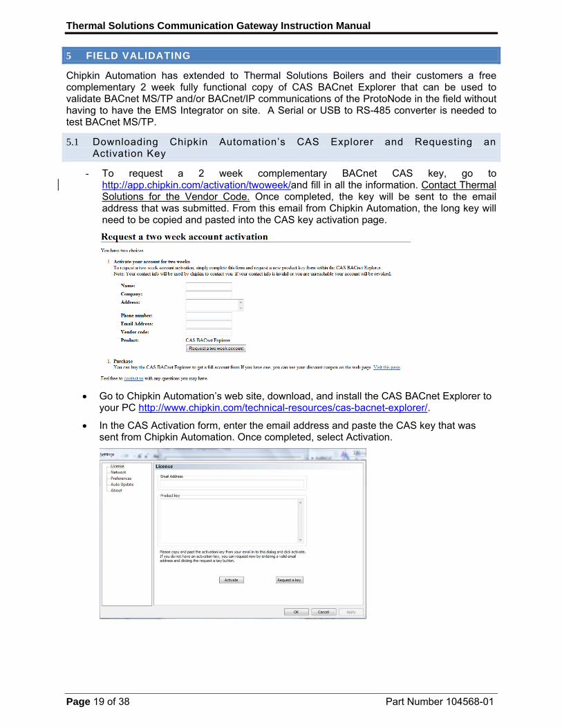
- To request a 2 week complementary BACnet CAS key, go to http://app.chipkin.com/activation/twoweek/and fill in all the information. Contact Thermal Solutions for the Vendor Code. Once completed, the key will be sent to the email address that was submitted. From this email from Chipkin Automation, the long key will need to be copied and pasted into the CAS key activation page.
Go to Chipkin Automation’s web site, download, and install the CAS BACnet Explorer to your PC http://www.chipkin.com/technical-resources/cas-bacnet-explorer/.
In the CAS Activation form, enter the email address and paste the CAS key that was sent from Chipkin Automation. Once completed, select Activation.

Thermal Solutions Communication Gateway Instruction Manual
Page 20 of 38 Part Number 104568-01
5.2 CAS BACnet Setup
These are the instructions to set CAS Explorer up for the first time on BACnet MS/TP and BACnet/IP.
5.2.1 CAS BACnet MS/TP Setup
Using the Serial or USB to RS-485 converter, connect it to your PC and the 3 Pin BACnet MS/TP connector on the ProtoNode RER.
In CAS Explorer, do the following: o Click on “Settings”. o Check the BACnet MSTP box and uncheck the BACnet IP and BACnet Ethernet
boxes. o Set the BACnet MSTP MAC address to 0. o Set the BACnet MSTP Baud Rate to 38400. o Click “Ok”. o On the bottom right-hand corner, make sure that the BACnet MSTP box is green. o Click on “Discover”. o Check all 4 boxes. o Click “Send”.
5.2.2 CAS BACnet BACnet/IP Setup
See Section 5.1 to set the IP address and subnet of the PC that will be running the CAS Explorer.
Connect a straight through or cross Ethernet cable from the PC to the ProtoNode. In CAS Explorer, do the following:
o Click on “Settings”. o Check the BACnet IP box and uncheck the BACnet MSTP and BACnet Ethernet
boxes. o In the “Select a Network Device” box, select the network card of the PC by
clicking on it. o Click “Ok”. o On the bottom right-hand corner, make sure that the BACnet IP box is green. o Click on “Discover”. o Check all 4 boxes. o Click “Send”.
Data is now available to view and edit. Simply select the “+” signs to open the branches. Data from all connected boilers is available.
Thermal Solutions Communication Gateway Instruction Manual
Page 21 of 38 Part Number 104568-01
Appendix A. Troubleshooting Tips
Appendix A.1. Check the Wiring Settings
No COMS on Modbus RTU side. If TX/RX is not flashing rapidly then there is a COM issue on the Modbus side and you need to check the following things: o Visual observations of LEDs on ProtoNode. See Appendix A.3 o Check baud rate, parity, data bits, stop bits o Check Modbus device address o Verify wiring o Verify all the Modbus RTU devices that were discovered in the FST Web
Commissioning screen . See Section 4.2
Field COM problems. o Visual observations of LEDs on ProtoNode. See Appendix A.3 o Visual dipswitch settings (using correct baud rate and device instance) o Verify IP address setting o Verify wiring
If the problem still exists, a log needs to be taken and sent to FieldServer.
Appendix A.2. Take Log With Our FieldServer Utilities
Once the log is complete, email it to [email protected]. The log will allow us to rapidly diagnose the problem.
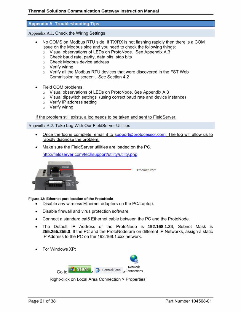
Make sure the FieldServer utilities are loaded on the PC.
http://fieldserver.com/techsupport/utility/utility.php
Figure 12: Ethernet port location of the ProtoNode
Disable any wireless Ethernet adapters on the PC/Laptop.
Disable firewall and virus protection software.
Connect a standard cat5 Ethernet cable between the PC and the ProtoNode.
The Default IP Address of the ProtoNode is 192.168.1.24, Subnet Mask is 255.255.255.0. If the PC and the ProtoNode are on different IP Networks, assign a static IP Address to the PC on the 192.168.1.xxx network.
For Windows XP:
Go to > >
Right-click on Local Area Connection > Properties

Thermal Solutions Communication Gateway Instruction Manual
Page 22 of 38 Part Number 104568-01
Highlight >
For Windows 7:
Go to > >
> >
Right-click on Local Area Connection > Properties
Highlight >
For Windows XP and Windows 7, select: Use the following IP address
Click twice
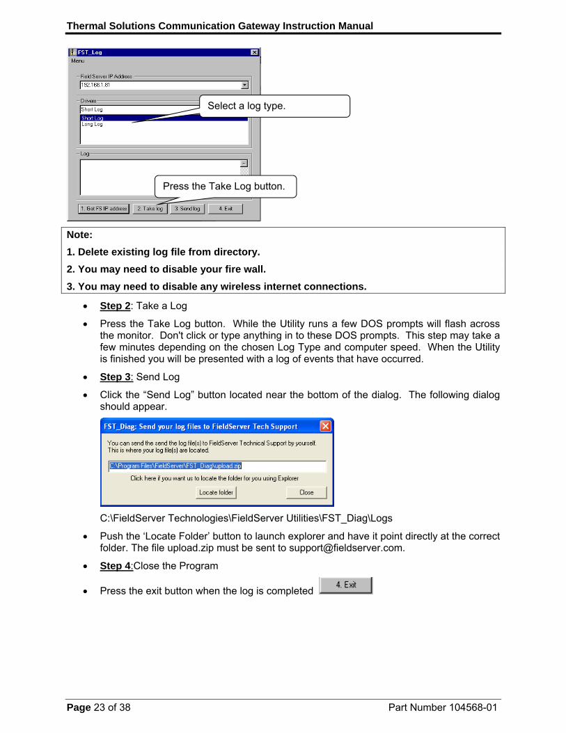
Double click on the FST Diag Utility.
Step 1: Select a Field Server IP Address.
The IP address can be entered manually or selected by clicking on button 1 using the Utility.
Type in the ProtoNode IP address Default IP Address is 192.168.1.24
Press here to retrieve the IP
Locate where the log is saved on
Thermal Solutions Communication Gateway Instruction Manual
Page 23 of 38 Part Number 104568-01
Note:
1. Delete existing log file from directory.
2. You may need to disable your fire wall.
3. You may need to disable any wireless internet connections.
Step 2: Take a Log
Press the Take Log button. While the Utility runs a few DOS prompts will flash across the monitor. Don't click or type anything in to these DOS prompts. This step may take a few minutes depending on the chosen Log Type and computer speed. When the Utility is finished you will be presented with a log of events that have occurred.
Step 3: Send Log
Click the “Send Log” button located near the bottom of the dialog. The following dialog should appear.
C:\FieldServer Technologies\FieldServer Utilities\FST_Diag\Logs
Push the ‘Locate Folder’ button to launch explorer and have it point directly at the correct folder. The file upload.zip must be sent to [email protected].
Step 4:Close the Program
Press the exit button when the log is completed
Select a log type.
Press the Take Log button.
Thermal Solutions Communication Gateway Instruction Manual
Page 24 of 38 Part Number 104568-01
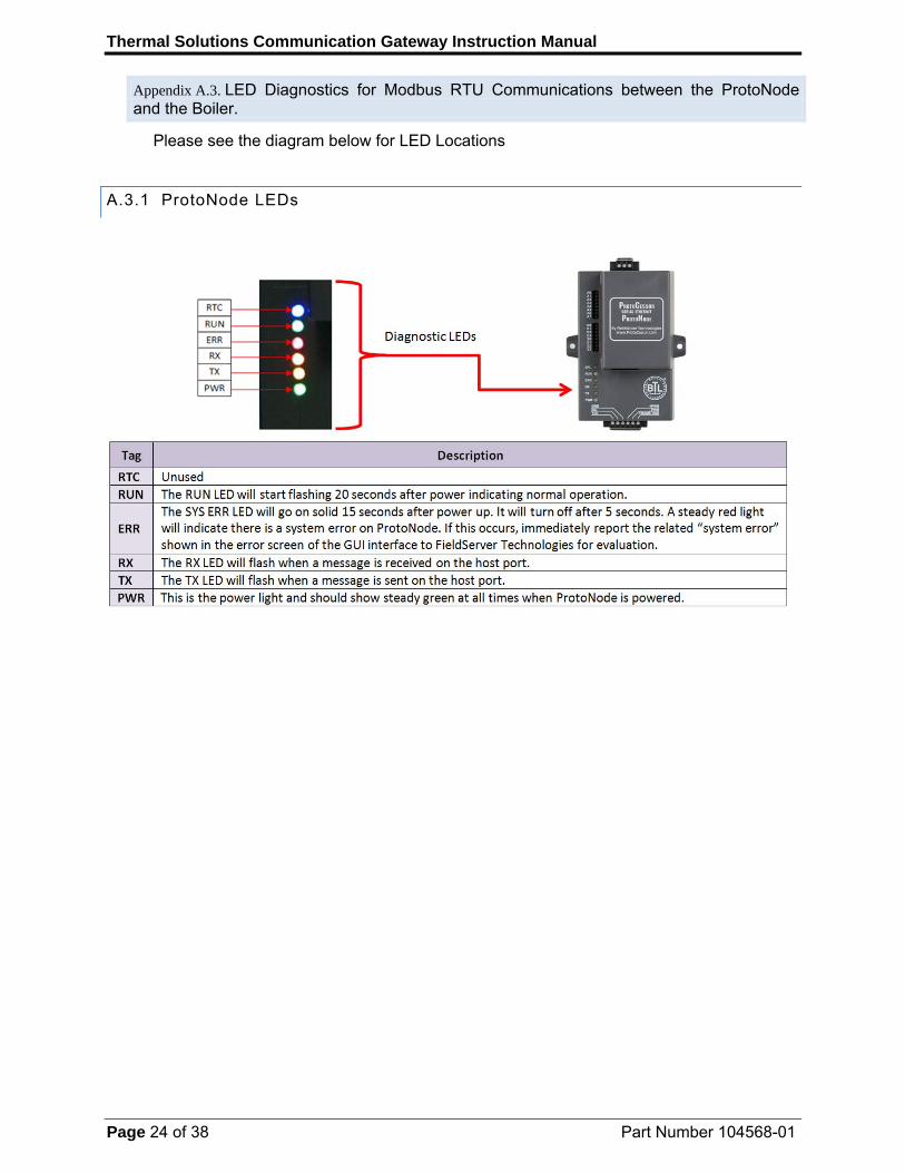
Appendix A.3. LED Diagnostics for Modbus RTU Communications between the ProtoNode and the Boiler.
Please see the diagram below for LED Locations
A.3.1 ProtoNode LEDs
Thermal Solutions Communication Gateway Instruction Manual
Page 25 of 38 Part Number 104568-01
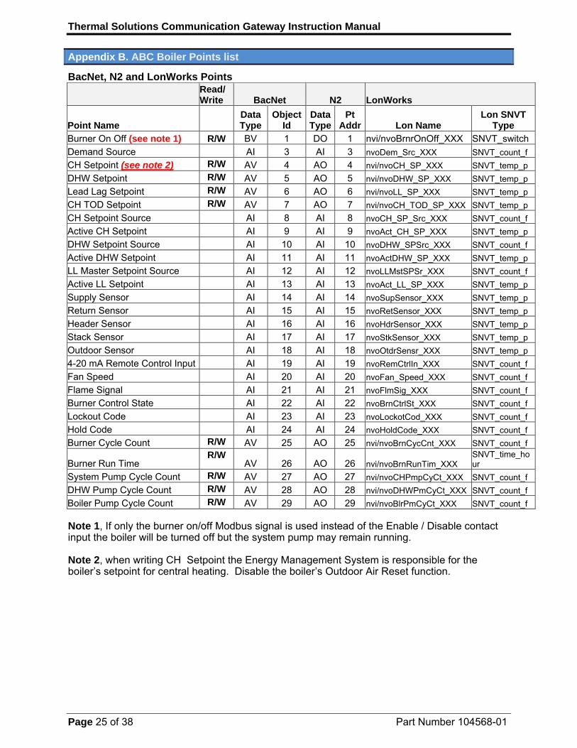
Appendix B. ABC Boiler Points list
BacNet, N2 and LonWorks Points
Read/ Write BacNet N2 LonWorks
Point Name
DataType
ObjectId
DataType
Pt Addr Lon Name
Lon SNVT Type
Burner On Off (see note 1) R/W BV 1 DO 1 nvi/nvoBrnrOnOff_XXX SNVT_switch
Demand Source AI 3 AI 3 nvoDem_Src_XXX SNVT_count_f
CH Setpoint (see note 2) R/W AV 4 AO 4 nvi/nvoCH_SP_XXX SNVT_temp_p
DHW Setpoint R/W AV 5 AO 5 nvi/nvoDHW_SP_XXX SNVT_temp_p
Lead Lag Setpoint R/W AV 6 AO 6 nvi/nvoLL_SP_XXX SNVT_temp_p
CH TOD Setpoint R/W AV 7 AO 7 nvi/nvoCH_TOD_SP_XXX SNVT_temp_p
CH Setpoint Source AI 8 AI 8 nvoCH_SP_Src_XXX SNVT_count_f
Active CH Setpoint AI 9 AI 9 nvoAct_CH_SP_XXX SNVT_temp_p
DHW Setpoint Source AI 10 AI 10 nvoDHW_SPSrc_XXX SNVT_count_f
Active DHW Setpoint AI 11 AI 11 nvoActDHW_SP_XXX SNVT_temp_p
LL Master Setpoint Source AI 12 AI 12 nvoLLMstSPSr_XXX SNVT_count_f
Active LL Setpoint AI 13 AI 13 nvoAct_LL_SP_XXX SNVT_temp_p
Supply Sensor AI 14 AI 14 nvoSupSensor_XXX SNVT_temp_p
Return Sensor AI 15 AI 15 nvoRetSensor_XXX SNVT_temp_p
Header Sensor AI 16 AI 16 nvoHdrSensor_XXX SNVT_temp_p
Stack Sensor AI 17 AI 17 nvoStkSensor_XXX SNVT_temp_p
Outdoor Sensor AI 18 AI 18 nvoOtdrSensr_XXX SNVT_temp_p
4-20 mA Remote Control Input AI 19 AI 19 nvoRemCtrlIn_XXX SNVT_count_f
Fan Speed AI 20 AI 20 nvoFan_Speed_XXX SNVT_count_f
Flame Signal AI 21 AI 21 nvoFlmSig_XXX SNVT_count_f
Burner Control State AI 22 AI 22 nvoBrnCtrlSt_XXX SNVT_count_f
Lockout Code AI 23 AI 23 nvoLockotCod_XXX SNVT_count_f
Hold Code AI 24 AI 24 nvoHoldCode_XXX SNVT_count_f
Burner Cycle Count R/W AV 25 AO 25 nvi/nvoBrnCycCnt_XXX SNVT_count_f
Burner Run Time R/W
AV 26 AO 26 nvi/nvoBrnRunTim_XXX SNVT_time_hour
System Pump Cycle Count R/W AV 27 AO 27 nvi/nvoCHPmpCyCt_XXX SNVT_count_f
DHW Pump Cycle Count R/W AV 28 AO 28 nvi/nvoDHWPmCyCt_XXX SNVT_count_f
Boiler Pump Cycle Count R/W AV 29 AO 29 nvi/nvoBlrPmCyCt_XXX SNVT_count_f Note 1, If only the burner on/off Modbus signal is used instead of the Enable / Disable contact input the boiler will be turned off but the system pump may remain running. Note 2, when writing CH Setpoint the Energy Management System is responsible for the boiler’s setpoint for central heating. Disable the boiler’s Outdoor Air Reset function.
Thermal Solutions Communication Gateway Instruction Manual
Page 26 of 38 Part Number 104568-01
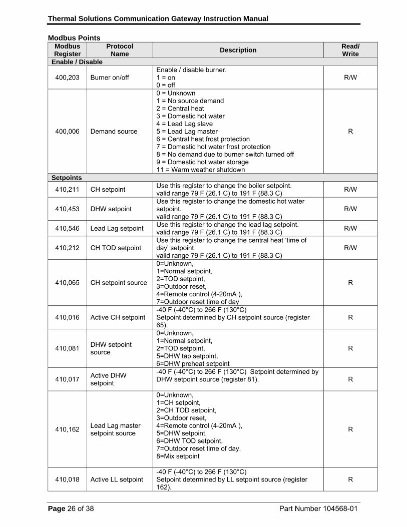
Modbus Points Modbus Register
Protocol Name
Description Read/ Write
Enable / Disable
400,203 Burner on/off Enable / disable burner. 1 = on 0 = off
R/W
400,006 Demand source
0 = Unknown 1 = No source demand 2 = Central heat 3 = Domestic hot water 4 = Lead Lag slave 5 = Lead Lag master 6 = Central heat frost protection 7 = Domestic hot water frost protection 8 = No demand due to burner switch turned off 9 = Domestic hot water storage 11 = Warm weather shutdown
R
Setpoints
410,211 CH setpoint Use this register to change the boiler setpoint. valid range 79 F (26.1 C) to 191 F (88.3 C)
R/W
410,453 DHW setpoint Use this register to change the domestic hot water setpoint. valid range 79 F (26.1 C) to 191 F (88.3 C)
R/W
410,546 Lead Lag setpoint Use this register to change the lead lag setpoint. valid range 79 F (26.1 C) to 191 F (88.3 C)
R/W
410,212 CH TOD setpoint Use this register to change the central heat ‘time of day’ setpoint valid range 79 F (26.1 C) to 191 F (88.3 C)
R/W
410,065 CH setpoint source
0=Unknown, 1=Normal setpoint, 2=TOD setpoint, 3=Outdoor reset, 4=Remote control (4-20mA ), 7=Outdoor reset time of day
R
410,016 Active CH setpoint -40 F (-40°C) to 266 F (130°C) Setpoint determined by CH setpoint source (register 65).
R
410,081 DHW setpoint source
0=Unknown, 1=Normal setpoint, 2=TOD setpoint, 5=DHW tap setpoint, 6=DHW preheat setpoint
R
410,017 Active DHW setpoint
-40 F (-40°C) to 266 F (130°C) Setpoint determined by DHW setpoint source (register 81).
R
410,162 Lead Lag master setpoint source
0=Unknown, 1=CH setpoint, 2=CH TOD setpoint, 3=Outdoor reset, 4=Remote control (4-20mA ), 5=DHW setpoint, 6=DHW TOD setpoint, 7=Outdoor reset time of day, 8=Mix setpoint
R
410,018 Active LL setpoint -40 F (-40°C) to 266 F (130°C) Setpoint determined by LL setpoint source (register 162).
R
Thermal Solutions Communication Gateway Instruction Manual
Page 27 of 38 Part Number 104568-01
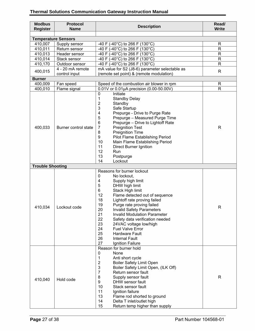
Modbus Register
Protocol Name
Description Read/ Write
Temperature Sensors
410,007 Supply sensor -40 F (-40°C) to 266 F (130°C) R 410,011 Return sensor -40 F (-40°C) to 266 F (130°C) R 410,013 Header sensor -40 F (-40°C) to 266 F (130°C) R 410,014 Stack sensor -40 F (-40°C) to 266 F (130°C) R 410,170 Outdoor sensor -40 F (-40°C) to 266 F (130°C) R
400,015 4 - 20 mA remote control input
mA value for S2 (J8-6) parameter selectable as (remote set point) & (remote modulation)
R
Burner 400,009 Fan speed Speed of the combustion air blower in rpm R 400,010 Flame signal 0.01V or 0.01μA precision (0.00-50.00V) R
400,033 Burner control state
0 Initiate 1 Standby Delay 2 Standby 3 Safe Startup 4 Prepurge - Drive to Purge Rate 5 Prepurge – Measured Purge Time 6 Prepurge – Drive to Lightoff Rate 7 Preignition Test 8 Preignition Time 9 Pilot Flame Establishing Period 10 Main Flame Establishing Period 11 Direct Burner Ignition 12 Run 13 Postpurge 14 Lockout
R
Trouble Shooting
410,034 Lockout code
Reasons for burner lockout 0 No lockout, 4 Supply high limit 5 DHW high limit 6 Stack High limit 12 Flame detected out of sequence 18 Lightoff rate proving failed 19 Purge rate proving failed 20 Invalid Safety Parameters 21 Invalid Modulation Parameter 22 Safety data verification needed 23 24VAC voltage low/high 24 Fuel Valve Error 25 Hardware Fault 26 Internal Fault 27 Ignition Failure
R
410,040
Hold code
Reason for burner hold 0 None 1 Anti short cycle 2 Boiler Safety Limit Open 3 Boiler Safety Limit Open, (ILK Off) 7 Return sensor fault 8 Supply sensor fault 9 DHW sensor fault 10 Stack sensor fault 11 Ignition failure 13 Flame rod shorted to ground 14 Delta T inlet/outlet high 15 Return temp higher than supply
R

Thermal Solutions Communication Gateway Instruction Manual
Page 28 of 38 Part Number 104568-01
Modbus Register
Protocol Name
Description Read/ Write
16 Supply temp has risen too quickly 17 Fan speed not proved 23 24VAC voltage low/high 25 Hardware Fault 27 Ignition Failure
Statistics 400,128- 400,129
Burner cycle count 0-999,999 (U32) R/W
400,130- 400,131
Burner run time Hours (U32) R/W
400,132- 400,133
System pump cycle count
0-999,999 (U32) R/W
400,134- 400,135
DHW pump cycle count
0-999,999 (U32) R/W
400,138- 400,139
Boiler pump cycle count
0-999,999 (U32) R/W
Thermal Solutions Communication Gateway Instruction Manual
Page 29 of 38 Part Number 104568-01
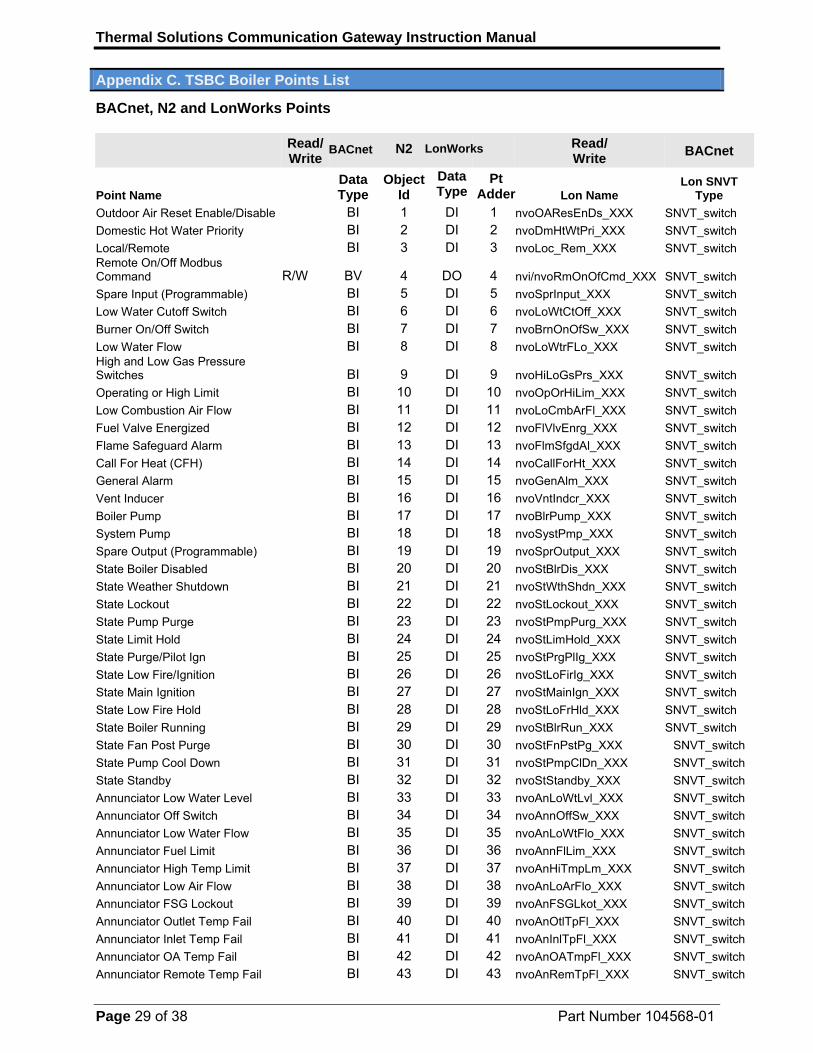
Appendix C. TSBC Boiler Points List
BACnet, N2 and LonWorks Points
Read/ Write
N2
Read/ Write
BACnet
Point Name Data Type
Object Id
Data Type Lon Name
Lon SNVT Type
Outdoor Air Reset Enable/Disable BI 1 DI 1 nvoOAResEnDs_XXX SNVT_switch
Domestic Hot Water Priority BI 2 DI 2 nvoDmHtWtPri_XXX SNVT_switch
Local/Remote BI 3 DI 3 nvoLoc_Rem_XXX SNVT_switch Remote On/Off Modbus Command R/W BV 4 DO 4 nvi/nvoRmOnOfCmd_XXX SNVT_switch
Spare Input (Programmable) BI 5 DI 5 nvoSprInput_XXX SNVT_switch
Low Water Cutoff Switch BI 6 DI 6 nvoLoWtCtOff_XXX SNVT_switch
Burner On/Off Switch BI 7 DI 7 nvoBrnOnOfSw_XXX SNVT_switch
Low Water Flow BI 8 DI 8 nvoLoWtrFLo_XXX SNVT_switch High and Low Gas Pressure Switches BI 9 DI 9 nvoHiLoGsPrs_XXX SNVT_switch
Operating or High Limit BI 10 DI 10 nvoOpOrHiLim_XXX SNVT_switch
Low Combustion Air Flow BI 11 DI 11 nvoLoCmbArFl_XXX SNVT_switch
Fuel Valve Energized BI 12 DI 12 nvoFlVlvEnrg_XXX SNVT_switch
Flame Safeguard Alarm BI 13 DI 13 nvoFlmSfgdAl_XXX SNVT_switch
Call For Heat (CFH) BI 14 DI 14 nvoCallForHt_XXX SNVT_switch
General Alarm BI 15 DI 15 nvoGenAlm_XXX SNVT_switch
Vent Inducer BI 16 DI 16 nvoVntIndcr_XXX SNVT_switch
Boiler Pump BI 17 DI 17 nvoBlrPump_XXX SNVT_switch
System Pump BI 18 DI 18 nvoSystPmp_XXX SNVT_switch
Spare Output (Programmable) BI 19 DI 19 nvoSprOutput_XXX SNVT_switch
State Boiler Disabled BI 20 DI 20 nvoStBlrDis_XXX SNVT_switch
State Weather Shutdown BI 21 DI 21 nvoStWthShdn_XXX SNVT_switch
State Lockout BI 22 DI 22 nvoStLockout_XXX SNVT_switch
State Pump Purge BI 23 DI 23 nvoStPmpPurg_XXX SNVT_switch
State Limit Hold BI 24 DI 24 nvoStLimHold_XXX SNVT_switch
State Purge/Pilot Ign BI 25 DI 25 nvoStPrgPlIg_XXX SNVT_switch
State Low Fire/Ignition BI 26 DI 26 nvoStLoFirIg_XXX SNVT_switch
State Main Ignition BI 27 DI 27 nvoStMainIgn_XXX SNVT_switch
State Low Fire Hold BI 28 DI 28 nvoStLoFrHld_XXX SNVT_switch
State Boiler Running BI 29 DI 29 nvoStBlrRun_XXX SNVT_switch
State Fan Post Purge BI 30 DI 30 nvoStFnPstPg_XXX SNVT_switch
State Pump Cool Down BI 31 DI 31 nvoStPmpClDn_XXX SNVT_switch
State Standby BI 32 DI 32 nvoStStandby_XXX SNVT_switch
Annunciator Low Water Level BI 33 DI 33 nvoAnLoWtLvl_XXX SNVT_switch
Annunciator Off Switch BI 34 DI 34 nvoAnnOffSw_XXX SNVT_switch
Annunciator Low Water Flow BI 35 DI 35 nvoAnLoWtFlo_XXX SNVT_switch
Annunciator Fuel Limit BI 36 DI 36 nvoAnnFlLim_XXX SNVT_switch
Annunciator High Temp Limit BI 37 DI 37 nvoAnHiTmpLm_XXX SNVT_switch
Annunciator Low Air Flow BI 38 DI 38 nvoAnLoArFlo_XXX SNVT_switch
Annunciator FSG Lockout BI 39 DI 39 nvoAnFSGLkot_XXX SNVT_switch
Annunciator Outlet Temp Fail BI 40 DI 40 nvoAnOtlTpFl_XXX SNVT_switch
Annunciator Inlet Temp Fail BI 41 DI 41 nvoAnInlTpFl_XXX SNVT_switch
Annunciator OA Temp Fail BI 42 DI 42 nvoAnOATmpFl_XXX SNVT_switch
Annunciator Remote Temp Fail BI 43 DI 43 nvoAnRemTpFl_XXX SNVT_switch
BACnet LonWorks
Pt Adder
Thermal Solutions Communication Gateway Instruction Manual
Page 30 of 38 Part Number 104568-01
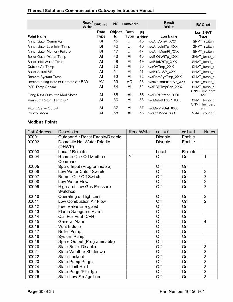
Read/ Write
N2
Read/ Write
BACnet
Point Name Data Type
Object Id
Data Type Lon Name
Lon SNVT Type
Annunciator Comm Fail BI 45 DI 45 nvoAnComFl_XXX SNVT_switch
Annunciator Low Inlet Temp BI 46 DI 46 nvoAnLoInlTp_XXX SNVT_switch
Annunciator Memory Failure BI 47 DI 47 nvoAnnMemFl_XXX SNVT_switch
Boiler Outlet Water Temp AI 48 AI 48 nvoBlOtlWtTp_XXX SNVT_temp_p
Boiler Inlet Water Temp AI 49 AI 49 nvoBlInlWtTp_XXX SNVT_temp_p
Outside Air Temp AI 50 AI 50 nvoOATmp_XXX SNVT_temp_p
Boiler Actual SP AI 51 AI 51 nvoBlrActSP_XXX SNVT_temp_p
Remote System Temp AI 52 AI 52 nvoRemSysTmp_XXX SNVT_temp_p
Remote Firing Rate or Remote SP R/W AV 53 AO 53 nvi/nvoRmFrRatSP_XXX SNVT_count_f
PCB Temp Sensor AI 54 AI 54 nvoPCBTmpSen_XXX SNVT_temp_p
Firing Rate Output to Mod Motor AI 55 AI 55 nvoFrRtOtMod_XXX SNVT_lev_perc
ent
Minimum Return Temp SP AI 56 AI 56 nvoMnRetTpSP_XXX SNVT_temp_p
Mixing Valve Output AI 57 AI 57 nvoMixVlvOut_XXX SNVT_lev_perc
ent
Control Mode AI 58 AI 58 nvoCtrlMode_XXX SNVT_count_f Modbus Points Coil Address Description Read/Write coil = 0 coil = 1 Notes00001 Outdoor Air Reset Enable/Disable Disable Enable 00002 Domestic Hot Water Priority
(DHWP) Disable Enable
00003 Local / Remote Local Remote 00004 Remote On / Off Modbus
Command Y Off On 1
00005 Spare Input (Programmable) Off On 00006 Low Water Cutoff Switch Off On 2 00007 Burner On / Off Switch Off On 2 00008 Low Water Flow Off On 2 00009 High and Low Gas Pressure
Switches Off On 2
00010 Operating or High Limit Off On 2 00011 Low Combustion Air Flow Off On 2 00012 Fuel Valve Energized Off On 00013 Flame Safeguard Alarm Off On 00014 Call For Heat (CFH) Off On 00015 General Alarm Off On 4 00016 Vent Inducer Off On 00017 Boiler Pump Off On 00018 System Pump Off On 00019 Spare Output (Programmable) Off On 00020 State Boiler Disabled Off On 3 00021 State Weather Shutdown Off On 3 00022 State Lockout Off On 3 00023 State Pump Purge Off On 3 00024 State Limit Hold Off On 3 00025 State Purge/Pilot Ign Off On 3 00026 State Low Fire/Ignition Off On 3
BACnet LonWorks
Pt Adder
Thermal Solutions Communication Gateway Instruction Manual
Page 31 of 38 Part Number 104568-01
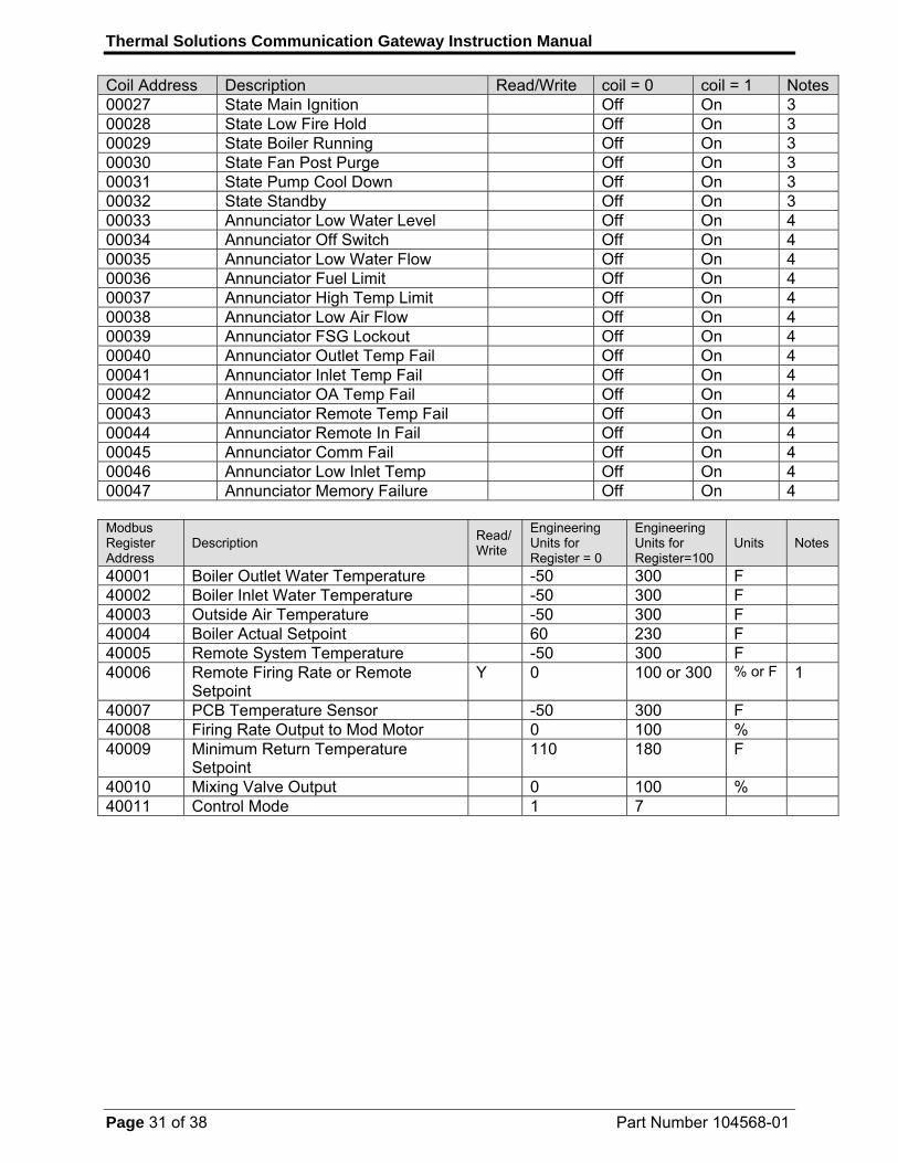
Coil Address Description Read/Write coil = 0 coil = 1 Notes00027 State Main Ignition Off On 3 00028 State Low Fire Hold Off On 3 00029 State Boiler Running Off On 3 00030 State Fan Post Purge Off On 3 00031 State Pump Cool Down Off On 3 00032 State Standby Off On 3 00033 Annunciator Low Water Level Off On 4 00034 Annunciator Off Switch Off On 4 00035 Annunciator Low Water Flow Off On 4 00036 Annunciator Fuel Limit Off On 4 00037 Annunciator High Temp Limit Off On 4 00038 Annunciator Low Air Flow Off On 4 00039 Annunciator FSG Lockout Off On 4 00040 Annunciator Outlet Temp Fail Off On 4 00041 Annunciator Inlet Temp Fail Off On 4 00042 Annunciator OA Temp Fail Off On 4 00043 Annunciator Remote Temp Fail Off On 4 00044 Annunciator Remote In Fail Off On 4 00045 Annunciator Comm Fail Off On 4 00046 Annunciator Low Inlet Temp Off On 4 00047 Annunciator Memory Failure Off On 4 Modbus Register Address
Description Read/ Write
Engineering Units for Register = 0
Engineering Units for Register=100
Units Notes
40001 Boiler Outlet Water Temperature -50 300 F 40002 Boiler Inlet Water Temperature -50 300 F 40003 Outside Air Temperature -50 300 F 40004 Boiler Actual Setpoint 60 230 F 40005 Remote System Temperature -50 300 F 40006 Remote Firing Rate or Remote
Setpoint Y 0 100 or 300 % or F 1
40007 PCB Temperature Sensor -50 300 F 40008 Firing Rate Output to Mod Motor 0 100 % 40009 Minimum Return Temperature
Setpoint 110 180 F
40010 Mixing Valve Output 0 100 % 40011 Control Mode 1 7
Thermal Solutions Communication Gateway Instruction Manual
Page 32 of 38 Part Number 104568-01
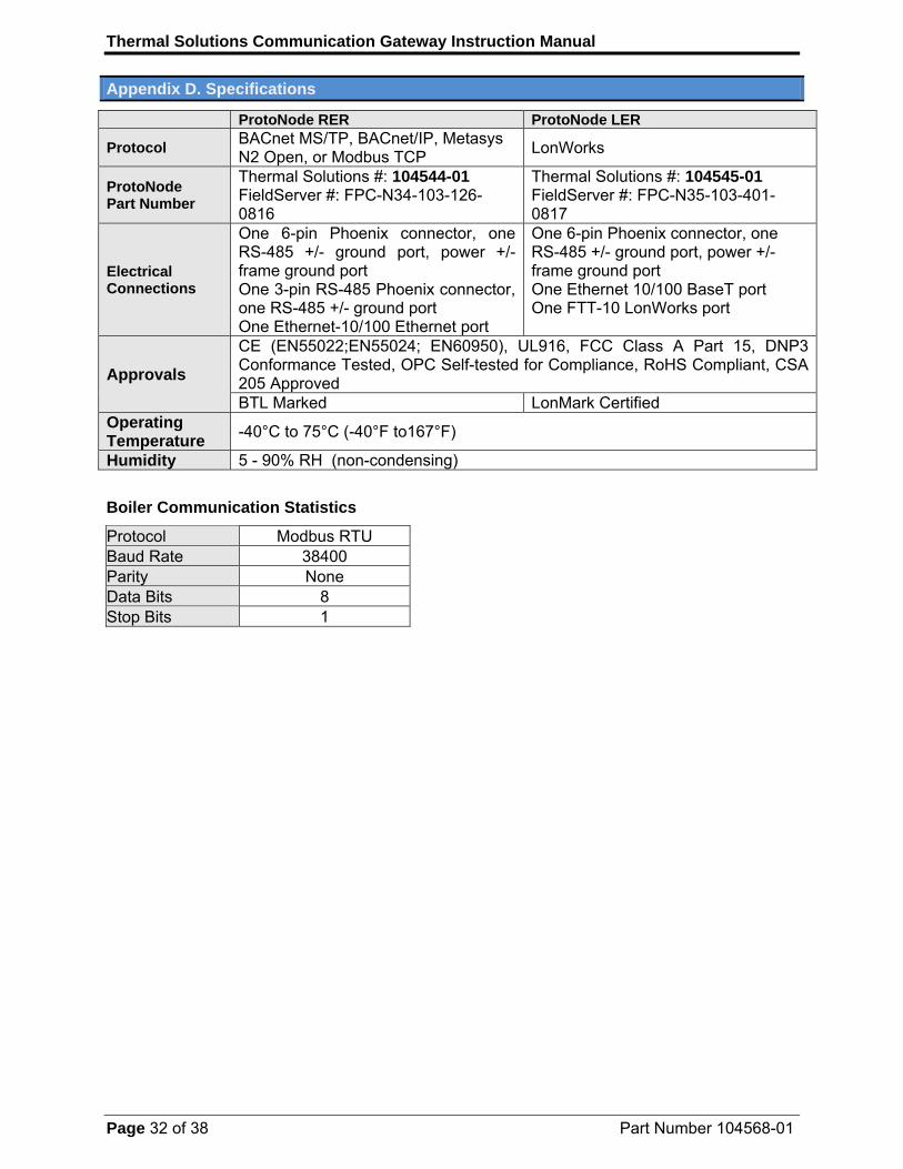
Appendix D. Specifications
ProtoNode RER ProtoNode LER
Protocol BACnet MS/TP, BACnet/IP, Metasys N2 Open, or Modbus TCP
LonWorks
ProtoNode Part Number
Thermal Solutions #: 104544-01 FieldServer #: FPC-N34-103-126-0816
Thermal Solutions #: 104545-01 FieldServer #: FPC-N35-103-401-0817
Electrical Connections
One 6-pin Phoenix connector, one RS-485 +/- ground port, power +/- frame ground port One 3-pin RS-485 Phoenix connector, one RS-485 +/- ground port One Ethernet-10/100 Ethernet port
One 6-pin Phoenix connector, one RS-485 +/- ground port, power +/- frame ground port One Ethernet 10/100 BaseT port One FTT-10 LonWorks port
Approvals
CE (EN55022;EN55024; EN60950), UL916, FCC Class A Part 15, DNP3 Conformance Tested, OPC Self-tested for Compliance, RoHS Compliant, CSA 205 Approved BTL Marked LonMark Certified
Operating Temperature
-40°C to 75°C (-40°F to167°F)
Humidity 5 - 90% RH (non-condensing)
Boiler Communication Statistics
Protocol Modbus RTU Baud Rate 38400 Parity None Data Bits 8 Stop Bits 1

Thermal Solutions Communication Gateway Instruction Manual
Page 33 of 38 Part Number 104568-01
Appendix E. Address DIP Switch Settings
A7 A6 A5 A4 A3 A2 A1 A0 Address Off Off Off Off Off Off Off Off 0 Off Off Off Off Off Off Off On 1 Off Off Off Off Off Off On Off 2 Off Off Off Off Off Off On On 3 Off Off Off Off Off On Off Off 4 Off Off Off Off Off On Off On 5 Off Off Off Off Off On On Off 6 Off Off Off Off Off On On On 7 Off Off Off Off On Off Off Off 8 Off Off Off Off On Off Off On 9 Off Off Off Off On Off On Off 10 Off Off Off Off On Off On On 11 Off Off Off Off On On Off Off 12 Off Off Off Off On On Off On 13 Off Off Off Off On On On Off 14 Off Off Off Off On On On On 15 Off Off Off On Off Off Off Off 16 Off Off Off On Off Off Off On 17 Off Off Off On Off Off On Off 18 Off Off Off On Off Off On On 19 Off Off Off On Off On Off Off 20 Off Off Off On Off On Off On 21 Off Off Off On Off On On Off 22 Off Off Off On Off On On On 23 Off Off Off On On Off Off Off 24 Off Off Off On On Off Off On 25 Off Off Off On On Off On Off 26 Off Off Off On On Off On On 27 Off Off Off On On On Off Off 28 Off Off Off On On On Off On 29 Off Off Off On On On On Off 30 Off Off Off On On On On On 31 Off Off On Off Off Off Off Off 32 Off Off On Off Off Off Off On 33 Off Off On Off Off Off On Off 34 Off Off On Off Off Off On On 35 Off Off On Off Off On Off Off 36 Off Off On Off Off On Off On 37 Off Off On Off Off On On Off 38 Off Off On Off Off On On On 39 Off Off On Off On Off Off Off 40 Off Off On Off On Off Off On 41 Off Off On Off On Off On Off 42 Off Off On Off On Off On On 43 Off Off On Off On On Off Off 44 Off Off On Off On On Off On 45 Off Off On Off On On On Off 46

Thermal Solutions Communication Gateway Instruction Manual
Page 34 of 38 Part Number 104568-01
A7 A6 A5 A4 A3 A2 A1 A0 Address Off Off On Off On On On On 47 Off Off On On Off Off Off Off 48 Off Off On On Off Off Off On 49 Off Off On On Off Off On Off 50 Off Off On On Off Off On On 51 Off Off On On Off On Off Off 52 Off Off On On Off On Off On 53 Off Off On On Off On On Off 54 Off Off On On Off On On On 55 Off Off On On On Off Off Off 56 Off Off On On On Off Off On 57 Off Off On On On Off On Off 58 Off Off On On On Off On On 59 Off Off On On On On Off Off 60 Off Off On On On On Off On 61 Off Off On On On On On Off 62 Off Off On On On On On On 63 Off On Off Off Off Off Off Off 64 Off On Off Off Off Off Off On 65 Off On Off Off Off Off On Off 66 Off On Off Off Off Off On On 67 Off On Off Off Off On Off Off 68 Off On Off Off Off On Off On 69 Off On Off Off Off On On Off 70 Off On Off Off Off On On On 71 Off On Off Off On Off Off Off 72 Off On Off Off On Off Off On 73 Off On Off Off On Off On Off 74 Off On Off Off On Off On On 75 Off On Off Off On On Off Off 76 Off On Off Off On On Off On 77 Off On Off Off On On On Off 78 Off On Off Off On On On On 79 Off On Off On Off Off Off Off 80 Off On Off On Off Off Off On 81 Off On Off On Off Off On Off 82 Off On Off On Off Off On On 83 Off On Off On Off On Off Off 84 Off On Off On Off On Off On 85 Off On Off On Off On On Off 86 Off On Off On Off On On On 87 Off On Off On On Off Off Off 88 Off On Off On On Off Off On 89 Off On Off On On Off On Off 90 Off On Off On On Off On On 91 Off On Off On On On Off Off 92 Off On Off On On On Off On 93 Off On Off On On On On Off 94 Off On Off On On On On On 95 Off On On Off Off Off Off Off 96

Thermal Solutions Communication Gateway Instruction Manual
Page 35 of 38 Part Number 104568-01
A7 A6 A5 A4 A3 A2 A1 A0 Address Off On On Off Off Off Off On 97 Off On On Off Off Off On Off 98 Off On On Off Off Off On On 99 Off On On Off Off On Off Off 100 Off On On Off Off On Off On 101 Off On On Off Off On On Off 102 Off On On Off Off On On On 103 Off On On Off On Off Off Off 104 Off On On Off On Off Off On 105 Off On On Off On Off On Off 106 Off On On Off On Off On On 107 Off On On Off On On Off Off 108 Off On On Off On On Off On 109 Off On On Off On On On Off 110 Off On On Off On On On On 111 Off On On On Off Off Off Off 112 Off On On On Off Off Off On 113 Off On On On Off Off On Off 114 Off On On On Off Off On On 115 Off On On On Off On Off Off 116 Off On On On Off On Off On 117 Off On On On Off On On Off 118 Off On On On Off On On On 119 Off On On On On Off Off Off 120 Off On On On On Off Off On 121 Off On On On On Off On Off 122 Off On On On On Off On On 123 Off On On On On On Off Off 124 Off On On On On On Off On 125 Off On On On On On On Off 126 Off On On On On On On On 127 On Off Off Off Off Off Off Off 128 On Off Off Off Off Off Off On 129 On Off Off Off Off Off On Off 130 On Off Off Off Off Off On On 131 On Off Off Off Off On Off Off 132 On Off Off Off Off On Off On 133 On Off Off Off Off On On Off 134 On Off Off Off Off On On On 135 On Off Off Off On Off Off Off 136 On Off Off Off On Off Off On 137 On Off Off Off On Off On Off 138 On Off Off Off On Off On On 139 On Off Off Off On On Off Off 140 On Off Off Off On On Off On 141 On Off Off Off On On On Off 142 On Off Off Off On On On On 143 On Off Off On Off Off Off Off 144 On Off Off On Off Off Off On 145 On Off Off On Off Off On Off 146

Thermal Solutions Communication Gateway Instruction Manual
Page 36 of 38 Part Number 104568-01
A7 A6 A5 A4 A3 A2 A1 A0 Address On Off Off On Off Off On On 147 On Off Off On Off On Off Off 148 On Off Off On Off On Off On 149 On Off Off On Off On On Off 150 On Off Off On Off On On On 151 On Off Off On On Off Off Off 152 On Off Off On On Off Off On 153 On Off Off On On Off On Off 154 On Off Off On On Off On On 155 On Off Off On On On Off Off 156 On Off Off On On On Off On 157 On Off Off On On On On Off 158 On Off Off On On On On On 159 On Off On Off Off Off Off Off 160 On Off On Off Off Off Off On 161 On Off On Off Off Off On Off 162 On Off On Off Off Off On On 163 On Off On Off Off On Off Off 164 On Off On Off Off On Off On 165 On Off On Off Off On On Off 166 On Off On Off Off On On On 167 On Off On Off On Off Off Off 168 On Off On Off On Off Off On 169 On Off On Off On Off On Off 170 On Off On Off On Off On On 171 On Off On Off On On Off Off 172 On Off On Off On On Off On 173 On Off On Off On On On Off 174 On Off On Off On On On On 175 On Off On On Off Off Off Off 176 On Off On On Off Off Off On 177 On Off On On Off Off On Off 178 On Off On On Off Off On On 179 On Off On On Off On Off Off 180 On Off On On Off On Off On 181 On Off On On Off On On Off 182 On Off On On Off On On On 183 On Off On On On Off Off Off 184 On Off On On On Off Off On 185 On Off On On On Off On Off 186 On Off On On On Off On On 187 On Off On On On On Off Off 188 On Off On On On On Off On 189 On Off On On On On On Off 190 On Off On On On On On On 191 On On Off Off Off Off Off Off 192 On On Off Off Off Off Off On 193 On On Off Off Off Off On Off 194 On On Off Off Off Off On On 195 On On Off Off Off On Off Off 196

Thermal Solutions Communication Gateway Instruction Manual
Page 37 of 38 Part Number 104568-01
A7 A6 A5 A4 A3 A2 A1 A0 Address On On Off Off Off On Off On 197 On On Off Off Off On On Off 198 On On Off Off Off On On On 199 On On Off Off On Off Off Off 200 On On Off Off On Off Off On 201 On On Off Off On Off On Off 202 On On Off Off On Off On On 203 On On Off Off On On Off Off 204 On On Off Off On On Off On 205 On On Off Off On On On Off 206 On On Off Off On On On On 207 On On Off On Off Off Off Off 208 On On Off On Off Off Off On 209 On On Off On Off Off On Off 210 On On Off On Off Off On On 211 On On Off On Off On Off Off 212 On On Off On Off On Off On 213 On On Off On Off On On Off 214 On On Off On Off On On On 215 On On Off On On Off Off Off 216 On On Off On On Off Off On 217 On On Off On On Off On Off 218 On On Off On On Off On On 219 On On Off On On On Off Off 220 On On Off On On On Off On 221 On On Off On On On On Off 222 On On Off On On On On On 223 On On On Off Off Off Off Off 224 On On On Off Off Off Off On 225 On On On Off Off Off On Off 226 On On On Off Off Off On On 227 On On On Off Off On Off Off 228 On On On Off Off On Off On 229 On On On Off Off On On Off 230 On On On Off Off On On On 231 On On On Off On Off Off Off 232 On On On Off On Off Off On 233 On On On Off On Off On Off 234 On On On Off On Off On On 235 On On On Off On On Off Off 236 On On On Off On On Off On 237 On On On Off On On On Off 238 On On On Off On On On On 239 On On On On Off Off Off Off 240 On On On On Off Off Off On 241 On On On On Off Off On Off 242 On On On On Off Off On On 243 On On On On Off On Off Off 244 On On On On Off On Off On 245 On On On On Off On On Off 246

Thermal Solutions Communication Gateway Instruction Manual
Page 38 of 38 Part Number 104568-01
A7 A6 A5 A4 A3 A2 A1 A0 Address On On On On Off On On On 247 On On On On On Off Off Off 248 On On On On On Off Off On 249 On On On On On Off On Off 250 On On On On On Off On On 251 On On On On On On Off Off 252 On On On On On On Off On 253 On On On On On On On Off 254 On On On On On On On On 255