A convenient probe for the 2D thermal detection of fouling ...
THERMAL PROTECTION OF THE HUYGENS PROBE DURING TITAN ENTRY:
LAST QUESTIONS
Jean-Marc BOUILLY (1)
(1) EADS SPACE Transportation - BP 11, 33 165 SAINT-MÉDARD-EN-JALLES Cedex, France
ABSTRACT CASSINI-HUYGENS mission is a cooperation between NASA and ESA, dedicated to the exploration of the Saturnian system. In the framework of this mission, the entry of the HUYGENS probe in the atmosphere of TITAN will be of major scientific interest. One of the essential points of the HUYGENS mission is therefore the good behavior of the thermal shield designed to maintain the aerodynamic shape and to protect the probe from excessive heating during the atmospheric entry on TITAN. The design and the qualification of this thermal shield were carried out between 1992 and 1995 (development phase). Currently, the final definition of mission parameters is being completed. As the performance of the thermal shield is one of all the parameters considered at system level, it is therefore necessary to reassess the thermal response of the TPS, taking into account some updated information that was not yet available during the development phase. After some recall of the results of 1992 to 1995, the paper will present a status of the current work on TPS. 1. GENERALITIES ABOUT HUYGENS TPS
1.1 CASSINI - HUYGENS mission
Cassini-Huygens is a joint NASA/ESA planetary exploration mission to the Saturnian system. The mission has two components, an orbiter, which will explore the entire system, and a descent probe, which will investigate Saturn's largest moon, Titan. Cassini, the Saturn orbiter, was built by NASA's Jet Propulsion Laboratory. Huygens, the descent probe, and the associated communications equipment on the orbiter were supplied by ESA. The Cassini-Huygens spacecraft was launched on October 15th 1997. After a 7 years interplanetary journey, it has been inserted into orbit around Saturn on July 1st 2004. The Huygens probe will be separated from Cassini on December 25th 2004, and will finally enter the atmosphere of Titan on January 14th 2005. Several experiments will be activated during the descent phase, which will be between 2 and 3 hours long.
1.2 Industrial organization (HUYGENS TPS)
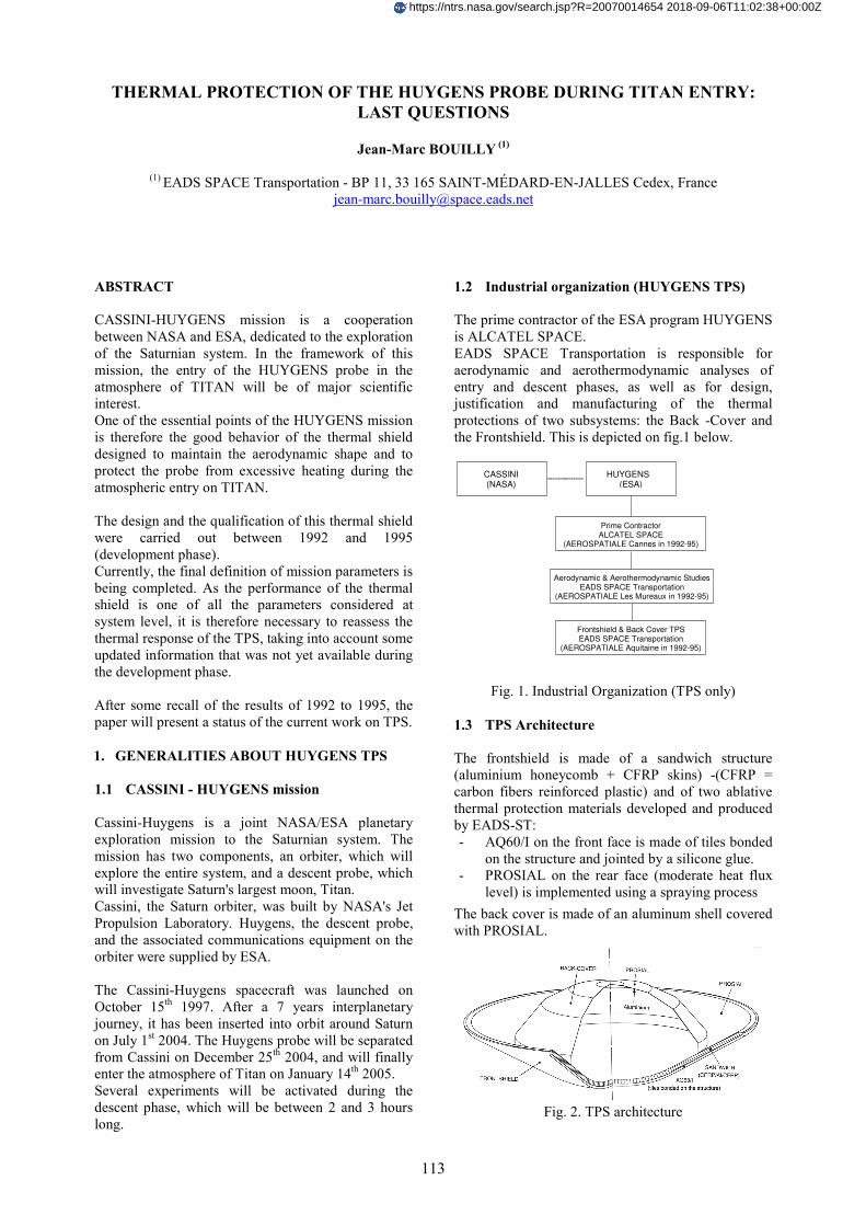
The prime contractor of the ESA program HUYGENS is ALCATEL SPACE. EADS SPACE Transportation is responsible for aerodynamic and aerothermodynamic analyses of entry and descent phases, as well as for design, justification and manufacturing of the thermal protections of two subsystems: the Back -Cover and the Frontshield. This is depicted on fig.1 below.
HUYGENS (ESA)
Prime Contractor ALCATEL SPACE
(AEROSPATIALE Cannes in 1992-95)
CASSINI (NASA)
Aerodynamic & Aerothermodynamic Studies EADS SPACE Transportation
(AEROSPATIALE Les Mureaux in 1992-95)
Frontshield & Back Cover TPS EADS SPACE Transportation
(AEROSPATIALE Aquitaine in 1992-95)
Fig. 1. Industrial Organization (TPS only)
1.3 TPS Architecture
The frontshield is made of a sandwich structure (aluminium honeycomb + CFRP skins) -(CFRP = carbon fibers reinforced plastic) and of two ablative thermal protection materials developed and produced by EADS-ST: - AQ60/I on the front face is made of tiles bonded
on the structure and jointed by a silicone glue.
- PROSIAL on the rear face (moderate heat flux
level) is implemented using a spraying process
The back cover is made of an aluminum shell covered
with PROSIAL.
Fig. 2. TPS architecture
113
https://ntrs.nasa.gov/search.jsp?R=20070014654 2018-09-06T11:02:38+00:00Z

1.4 Entry conditions: (atmosphere, heat flux,
shear stress, pressure)
The main constituent of TITAN atmosphere is nitrogen (N2). Two other constituents are identified: argon (Ar) and methane (CH4). During entry, the methane dissociates in the shock layer, leading to the formation of CN. This molecule generates a high radiation in the narrow UV band. Though the convective heat flux is not very sensitive to atmosphere composition, the radiative heat flux can on the contrary reach very high values, especially for trajectories with highest FPA (Flight path angle). The table 1 below summarizes the main characteristics of the probe, TPS, and environment during entry. Table 1 - Main characteristics of HUYGENS TPS
HUYGENS Mission
Entry on Titan (Saturn's moon) after a 7 years travel with CASSINI
duration 300 sec.
max. heat flux (front face)
1400 kW/m2 (20 sec.)
max. heat flux (rear face)
30 to 120 kW/m²
max. shear stress 135 Pa (area close to edge of decelerator)
max. pressure 0.1 atm. (stagn. point)
Entry characteristics (development phase values)
worst atmosphere
77% N2, 20% Ar, 3% CH4
T.P. material AQ60/I
Density d = 0.28
Thickness 17.4 to 18.2 mm
T.P. mass 30 kg + 9 kg glue & joints
Structure CFRP honeycomb
Structure mass 32 kg
Frontshield
total mass 76 kg (including 5kg PROSIAL on back face)
T.P. material PROSIAL
Density d = 0.54 to 0.60
Thickness 0.3 to 3.1 mm
T.P. mass 5.2 kg
Structure stiffened aluminium (0.8 mm)
Rear part and back-cover
total mass 17 kg
Total height 0.97 m
Max. diameter 2.70 m Whole Entry Module
Total mass of the vehicle
320 kg (actual mass) 335 kg (1992 hypothesis)
1.5 Thermal protection materials
AQ60, an EADS-ST trademark, is a felt made of short fibers. It is obtained (fig.3) by vacuum processing of an aqueous suspension of silica fibers. The material is then reinforced by an impregnation of Phenolic resin (representing 30% of the total mass).
AQ 60/I is the reinforced felt. The final density is 0.28, with a total porosity around 84 %. The volumic ratio of Silica is 10% and the one of resin is 6 %. Remark: it must be noticed that the material used for HUYGENS is AQ60/I even though it is more often called AQ60, using an abusive contraction.
Due to its non-mineral bonding agent, this material undergoes pyrolysis for temperatures between 200° C and 1000° C. However, following pyrolysis the material is still self-supporting and becomes a very efficient thermal insulator with a quite high ablation temperature. It is also worth noting the quite good mechanical properties. This is of interest for withstanding thermomechanical entry loads. For its industrial applications, this material has been applied following two main ways: - thermal protection covers directly molded with
the shape of equipment (military programs). - tiles or panels, after a precise machining
(HUYGENS)
Fig. 3. Short description of AQ60/I manufacturing
PROSIAL 1000 is also an EADS-ST trademark: It is made up of a silicone elastomer with excellent thermal properties and of silica hollow spheres, making it possible to decrease density down to values of 0.6 to 0.54. Prosial 1000 is directly sprayed onto the surface to be protected. 2. THERMAL QUALIFICATION TESTS of
HUYGENS TPS
2.1 General logic of the tests
Before being used for HUYGENS, these two materials had been developed for a quite different application. During the development phase, from 1992 to 1995, it was thus necessary to update and
Silica fibers in a solution of water + acetone + starch
Aspiration through a porous mold
Drying
Impregnation with phenolic resin
Polymerisation of phenolic resin
Machining (if a very precise shape is needed)
114

complete their characterizations, particularly for AQ60, for which solicitations are indeed much higher than on PROSIAL. The following objectives were reached successfully during the study, in order to demonstrate the satisfactory behavior of AQ60 in conditions representative of the HUYGENS entry: - validation of the choice of this material - update of the material data set thanks to thermal
and thermomechanical characterization tests - qualification of the tile arrangement (joints,
steps, possible defects, micrometeoroid impact) - thermomechanical qualification of the whole
heatshield The most specific physical aspects to consider were the following: - high heat fluxes in a non oxidizing atmosphere
as representative as possible of the Titan’s one (gas mixture N2, Ar, CH4, or pure N2)
- combination of high heat flux and aerodynamic shear
- thermomechanical effects The corresponding tests are recalled in next sections.
- Thermomechanical behavior stack AQ60/CFRP/sandwich
Plasma tests (IRS)
Plasma tests (SIMOUN)
- High heat flux - Limits
Validation and confirmation of AQ60 choice
- Combination of heat flux and shear load
Infrared tests (BATTELLE)
- Determination of thermal properties
Entry characterization tests (EADS-ST)
Complement and update of AQ60 characteristics for Huygens mission
Qualification of the tile arrangement
Thermomechanical qualification of the
heatshield
Cold elementary tests (EADS-ST)
Entry qualification tests (EADS-ST)
- Scale 1 structure
Figure 4. General logic of the tests
2.2 IRS stagnation point plasma tests
Plasma tests in stagnation point configuration [1,2,3] were performed in the plasma wind tunnel PWK2 of IRS (Institüt für Raumfahrtysteme) of the University of Stuttgart. A series of 17 tests was performed under various aerothermodynamic conditions - Titan atmosphere (77% N2, 20% Ar, 3% CH4) - Stagnation pressure: from 0.015 to 0.020 atm.
- Heat flux: from 600 to 2500 kW/m² Several other parameters were also analyzed: - Influence of atmosphere (Titan or pure N2) - Influence of joints - Influence of coating - Heat flux: constant value, or flight evolution The sample is positioned on a support fixed on a platform that can be moved with a high precision and speed, which allows realizing heat flux evolutions versus time, with various possible maximum values.
plasma source RD4
AQ60 sample
vacuum vessel
linearpyrometer LP2
Moving platform
Axisymetric flow
Fig. 5. Experimental setup for plasma tests at IRS-
PWK2
Fig. 6. AQ60 sample during IRS plasma test
These tests permitted to demonstrate the good behaviour of AQ60/I submitted to heat fluxes up to 2500 kW/m² in an atmosphere representative of Titan’s one (77% N2, 20% Ar, 3% CH4). They also demonstrated a good margin (without reaching an upper limit) with regard to heat flux level, which was necessary because of uncertainties on heat flux computations. Furthermore, they evidenced a good ablative behavior, with surface temperature and surface recession increasing regularly versus heat flux value. The exploitation of these tests permitted to determine the ablation law associated to this behavior. Finally, they proved the major influence of the atmosphere, with a better behavior than in air, by
115
comparison with previous results not detailed in this paper, obtained on SIMOUN with similar samples, configuration, and heat flux values. 2.3 SIMOUN PLASMA TESTS
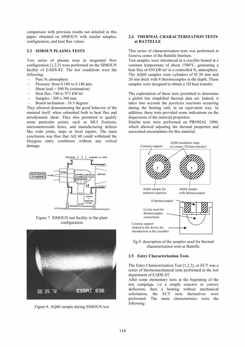
Two series of plasma tests in tangential flow configuration [1,2,3] were performed on the SIMOUN facility of EADS-ST. The test conditions were the following: - Pure N2 atmosphere - Pressure: from 0.100 to 0.140 atm. - Shear load = 500 Pa (estimation) - Heat flux: 740 to 973 kW/m² - Samples : 300 x 300 mm - Board inclination : 16.5 degrees They allowed demonstrating the good behavior of the material itself, when submitted both to heat flux and aerodynamic shear. They also permitted to qualify some particular points, such as MLI fixations, micrometeoroids holes, and manufacturing defects like wide joints, steps or local repairs. The main conclusion was thus that AQ 60 could withstand the Huygens entry conditions without any critical damage.
Figure 7. SIMOUN test facility in flat plate configuration
Figure 8. AQ60 sample during SIMOUN test
2.4 THERMAL CHARACTERIZATION TESTS
at BATTELLE
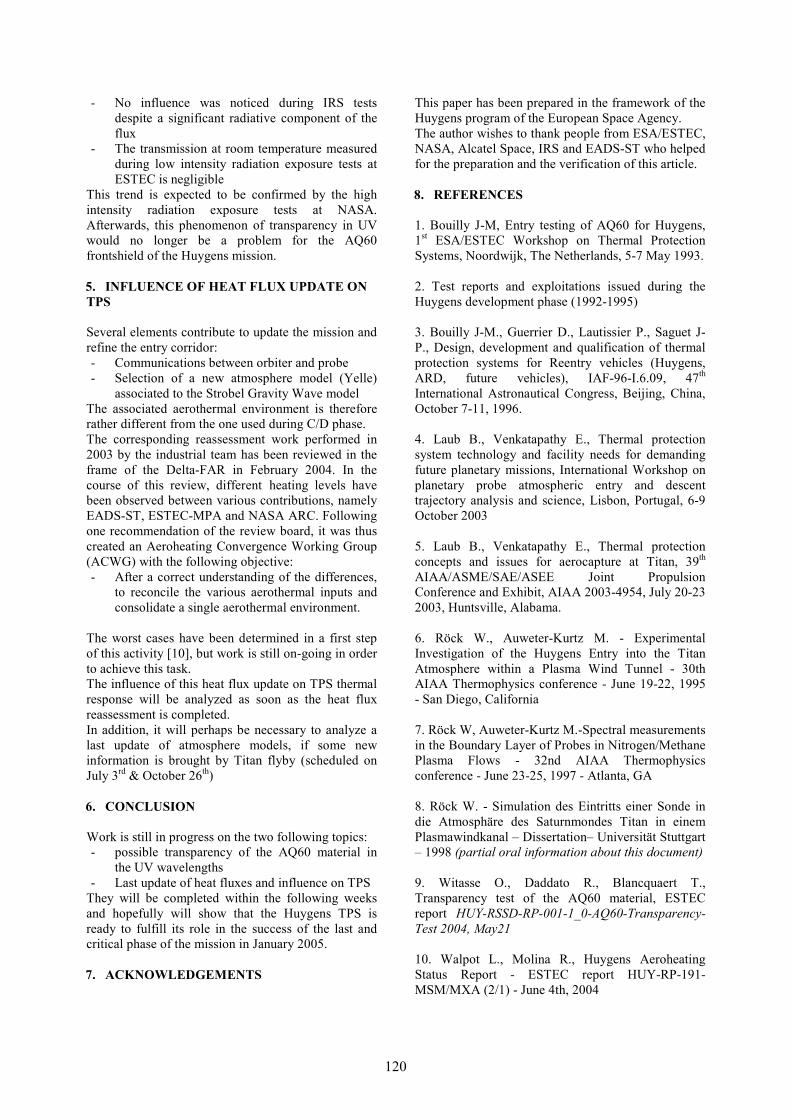
This series of characterization tests was performed at Geneva center of the Battelle Institute. Test samples were introduced in a crucible heated at a constant temperature of about 1580°C, generating a heat flux of 650 kW/m² in a controlled N2 atmosphere. The AQ60 samples were cylinders of Ø 20 mm and 20 mm thick with 8 thermocouples in the depth. These samples were designed to obtain a 1D heat transfer. The exploitation of these tests permitted to determine a global but simplified thermal data set. Indeed, it takes into account the pyrolysis reactions occurring during the heating only in an equivalent way. In addition, these tests provided some indications on the dispersions of the material properties. Similar tests were performed on PROSIAL 1000, which allowed adjusting the thermal properties and associated uncertainties for this material.
fig.9. description of the samples used for thermal
characterization tests at Battelle. 2.5 Entry Characterization Tests
The Entry Characterization Test [1,2,3], or ECT was a series of thermomechanical tests performed in the test department of EADS-ST. After some elementary tests at the beginning of the test campaign, i-e a simple concave or convex deflection, then a heating without mechanical solicitation, the ECT tests themselves were performed. The main characteristics were the following:
Ceramic support
AQ60 sample for material expertise
AQ60 sample with thermocouples
AQ60 insulation rings (to ensure 1D heat transfer)
8 thermocouples
Cavity used for thermocouples connections
Ceramic support (linked to the device for introduction in the crucible)
116

- Application by infrared lamps of a heat flux representative of the real mission
- Simultaneous application of a mechanical bending leading to tensile or compressive stressing according to the applied deflection.
- non oxidizing controlled atmosphere of pure N2 - 12 samples representative of the complete stack,
with actual design thickness: CFRP Honeycomb (long piece 800 x 40 mm) - glue - AQ60/I
These tests permitted to overcome the impossibility to determine mechanical properties at high temperature because of chemical transformations in the material. They also validated the thermo-mechanical behavior of AQ60/I tiles during entry, and permitted to deduce equivalent material data for theoretical analyses.
F compressive test
Heating = infrared lamps Mechanical loading = 4 points flexion test (convex or concave deflection) Atmosphere = pure N2
IR fluxes Reflector
N2 atm.
Fixed support Sandwich
AQ60
F tensile test
fig.10: schematic description of Entry Characterization Tests
2.6 Cold Elementary Test
The Cold Elementary Test [2,3], or CET showed that there was no failure mode under cold environment (-120°C), and permitted to determine the actual influence of glue and PROSIAL thermal expansions on the stack deflections. These tests were performed on samples representative of the stack of the frontshield. 2.7 Entry Qualification Test
The Entry Qualification Test [2,3], or EQT, permitted to demonstrate the good global behavior of the Frontshield during the entry phase. This was done by a simulation of the following parameters: initial cold temperatures (-60°C), neutral N2 atmosphere, entry heat fluxes simulated by infrared lamps, mechanical loads (i.e. external pressure and deceleration) simulated by a pressure difference between the back and front faces. The test specimen was made up of a flight representative structure partly covered on its front
face by AQ60/I tiles. This permitted to carry out two tests with the same thermal solicitation: the first one at the qualification level for mechanical loading, the second one at a higher value of mechanical loading to evidence some margins. This specific test facility (fig.11) was developed and operated by the test department of EADS-ST. It was composed of a large chamber that included the cooling, depressurization and heating devices.
fig.11: picture of EQT device
2.8 Conclusions at the end of development phase
After analyses and tests performed during the development phase (1992-1995), the qualification of the Huygens TPS was considered as successfully completed and both frontshield and back-cover were accepted for flight. 3. MISSION PREPARATION PHASE
In order to prepare the impending Huygens entry, the final definition of mission parameters is being completed. The performance of the thermal shield is one of all the parameters considered at system level and it is thus necessary to reassess the thermal response of the TPS. These last analyses must obviously take into account some updated information that was not yet available during the development phase 10 years ago. More particularly, two points have to be considered: - A possible transparency of the AQ60 material in
the UV wavelengths - Updated heat fluxes, with expected values
significantly higher than during the development phase.
Several actions are still on-going on these two topics, and a status of this current work is presented in the following sections.
117

4. AQ60 POSSIBLE TRANSPARENCY
4.1 Overview of the problem
As mentioned previously, due to the atmosphere composition, the entry velocity, and the shape of the probe, the heat shield undergoes both convective and radiative heat fluxes. More precisely, the radiative emission of the shock layer occurs in the narrow UV band. In the framework of studies about aerocapture mission at Titan [4,5], NASA experts identified possible uncertainties on performance of lightweight materials. Indeed, a general trend was suggested from Laser tests performed in the 80’s on several dozens of TP materials. The shorter the wavelength was, the larger became the absorption length. There is no available test result in UV wavelength for lightweight materials. The potential for in-depth absorption could thus be of concern for AQ60, since it could lead to char spallation that would significantly reduce its efficiency and lead to eventual additional heating of the underlying substructure. In order to evaluate the performance of candidate Titan TP materials exposed to UV radiation, NASA has decided to develop a specific facility based on a high-power Mercury-Xenon lamp that has a strong emission in the UV range. 4.2 Action plan
Based on above mentioned information, this topic was analyzed during the Delta-FAR (Flight acceptance review) held at the beginning of 2004. It was decided to initiate several actions in order to evaluate the influence of this phenomenon on the performance of the Huygens Frontshield. - Status on representativeness of development
phase tests wrt radiative emission in UV band - Status on representativeness of IRS test wrt
radiative emission of the flow in UV wavelength - Low intensity radiation exposure tests at ESTEC - High intensity radiation exposure tests at NASA The corresponding results are presented hereafter. 4.3 Representativeness of development phase
tests
Two families can be identified among the tests of the development phase: radiative and plasma tests. The radiative tests (BATTELLE, ECT, and EQT) were performed with an Infrared radiant source. No information about UV radiation can therefore be deduced from these tests. The SIMOUN plasma tests were carried out in a pure N2 tangential flow. There was therefore no radiation effect during these tests. On the other hand, most of the IRS tests were performed in an atmosphere comprised of N2, Ar and CH4. In addition, it must be highlighted that the introduction of methane was very spectacular,
inducing a high brightness of the flow [6]. Thus only IRS tests can be relevant with regard to UV radiation. 4.4 Representativeness of IRS tests
During the development phase, this problem of UV radiation had not been considered, and only the total heat flux had been measured for this test campaign. In order to evaluate if the test performed in 1992 could provide information about AQ60 possible transparency, some actions have been proposed but have not been selected for several reasons (delay, cost and uncertainties on the results). - reexploitation of the 1992 tests in order to
identify if such a phenomenon occurred. This would require a very precise thermal model while current data only lead to a satisfactory global resetting, remaining on purpose slightly conservative. Furthermore, very accurate measurements would be necessary whereas only one thermocouple was installed on each IRS sample.
- theoretical analysis and evaluation of the radiative emission of the flow
- complementary tests with same conditions as in 1992 and specific measurements (knowing that it is considered as difficult to perform radiative flux measurement in UV)
However, a synthetic analysis can be established, relying on experimental works conducted by IRS after the end of the Huygens development [6,7,8]. Indeed, an extensive characterization of Nitrogen/Methane plasma flows was undertaken from 1992 to 1998. A specific radiometer was developed and used to measure the radiation emitted by the flow [6]. In addition, a set of emission spectroscopy measurements was done for various combinations of N2/CH4 mixtures [7]. This allowed to evidence that some radiative heat flux occurred during these experiments, and that some emission could be observed around 380 nm, which corresponds to CN violet. A direct quantitative interpretation of these tests is not easy, because these are mainly local measurements in reduced solid angles. An estimation of the integrated value is provided in [8]: the radiative heat flux is 377 kW/m², which represents ≈20% of the corresponding total heat flux equal to 1800 kW/m². Even though some uncertainty must obviously be associated to this result, it shows that the radiative component of the flux can be considered as significant for the tests that were performed in 1992. However, no evident influence on material behavior was identified. This point is thus quite positive, even though the worst expected value of the radiative heat flux could be much higher than the experienced one of 377 kW/m².
118

4.5 Low intensity radiation exposure tests at
ESTEC
As recommended by the board of the Delta-FAR, elementary characterization tests on AQ60 were performed by ESTEC in March and April 2004 [9]. AQ60 samples of 40 x 40 mm x 1 to 5 mm thick (fig.12) were illuminated by a spectral Xenon lamp radiating at a wavelength of 377 nm, and the intensity of the light transmitted through the samples was recorded. The transmission was then calculated by comparison with transmission obtained with calibrated neutral density filters.
Fig. 12: AQ60 samples
The test device (fig.13) is operated at room temperature.
Fig. 13: Picture of test device (IS = Integrating Sphere; PMT=Photomultiplier)
Tests were carried out on 10 samples provided by EADS-ST. 8 of these samples were made of virgin material without coating, with different thickness between 2 and 5 mm (two 1 mm thick samples were machined by ESTEC from already tested specimen in order to complete a first set of results). The 2 other samples were made of char material issued from tested samples remaining from the 1993 ECT tests.
The results presented in the table 2 show a very low transmission in the UV through AQ60. This transmission is even lower for the pyrolised samples.
Table 2: samples thickness and transmission calculated from the measured signal
SampleThickness(mm)
Transmission
V1(bis) 1.00 1.79E-04
V7(bis) 1.10 1.35E-04
V2 2.12 7.77E-06
V3 3.10 1.20E-06
V4 3.10 1.27E-06
V5 4.08 1.82E-07
V6 4.10 1.57E-07
V8 5.05 5.20E-08
P1 4.06 8.00E-09
P2 4.08 6.00E-09 (V= virgin material. P= pyrolised material).
These results are very positive and they constitute the first step of the demonstration that the transparency of AQ60 in UV can be considered as a negligible phenomenon for the Huygens mission. 4.6 High intensity radiation exposure tests at
NASA
It is considered as very relevant to complete the previous results by tests at high temperature. With this aim, NASA proposed to include AQ60 samples in a test campaign prepared at NASA Ames for analyzing the performance of lightweight TP materials when exposed to high intensity UV radiation (cf. §4.1). EADS-ST provided 8 AQ60 samples (75 x 75 x 20 mm) for these tests. These samples include a central plug insert (diameter 30mm) in which several thermocouples must be installed by NASA.
Fig. 14: AQ60 samples for UV tests at NASA
Tests will be performed at different heat flux levels: 500, 1000 (tbc) and 1500 kW/m², generated by a high-power Mercury-Xenon lamp. The detailed missions and their durations are still to be precised. The performance of these tests is planned within a few weeks, as soon as the test device is available. 4.7 Conclusion
Available experimental results do not show any significant transparency of AQ60 in the UV:
119
- No influence was noticed during IRS tests despite a significant radiative component of the flux
- The transmission at room temperature measured during low intensity radiation exposure tests at ESTEC is negligible
This trend is expected to be confirmed by the high intensity radiation exposure tests at NASA. Afterwards, this phenomenon of transparency in UV would no longer be a problem for the AQ60 frontshield of the Huygens mission. 5. INFLUENCE OF HEAT FLUX UPDATE ON
TPS
Several elements contribute to update the mission and refine the entry corridor: - Communications between orbiter and probe - Selection of a new atmosphere model (Yelle)
associated to the Strobel Gravity Wave model The associated aerothermal environment is therefore rather different from the one used during C/D phase. The corresponding reassessment work performed in 2003 by the industrial team has been reviewed in the frame of the Delta-FAR in February 2004. In the course of this review, different heating levels have been observed between various contributions, namely EADS-ST, ESTEC-MPA and NASA ARC. Following one recommendation of the review board, it was thus created an Aeroheating Convergence Working Group (ACWG) with the following objective: - After a correct understanding of the differences,
to reconcile the various aerothermal inputs and consolidate a single aerothermal environment.
The worst cases have been determined in a first step of this activity [10], but work is still on-going in order to achieve this task. The influence of this heat flux update on TPS thermal response will be analyzed as soon as the heat flux reassessment is completed. In addition, it will perhaps be necessary to analyze a last update of atmosphere models, if some new information is brought by Titan flyby (scheduled on July 3rd & October 26th) 6. CONCLUSION
Work is still in progress on the two following topics: - possible transparency of the AQ60 material in
the UV wavelengths - Last update of heat fluxes and influence on TPS They will be completed within the following weeks and hopefully will show that the Huygens TPS is ready to fulfill its role in the success of the last and critical phase of the mission in January 2005. 7. ACKNOWLEDGEMENTS
This paper has been prepared in the framework of the Huygens program of the European Space Agency. The author wishes to thank people from ESA/ESTEC, NASA, Alcatel Space, IRS and EADS-ST who helped for the preparation and the verification of this article. 8. REFERENCES
1. Bouilly J-M, Entry testing of AQ60 for Huygens, 1st ESA/ESTEC Workshop on Thermal Protection Systems, Noordwijk, The Netherlands, 5-7 May 1993. 2. Test reports and exploitations issued during the Huygens development phase (1992-1995) 3. Bouilly J-M., Guerrier D., Lautissier P., Saguet J-P., Design, development and qualification of thermal protection systems for Reentry vehicles (Huygens, ARD, future vehicles), IAF-96-I.6.09, 47th International Astronautical Congress, Beijing, China, October 7-11, 1996. 4. Laub B., Venkatapathy E., Thermal protection system technology and facility needs for demanding future planetary missions, International Workshop on planetary probe atmospheric entry and descent trajectory analysis and science, Lisbon, Portugal, 6-9 October 2003 5. Laub B., Venkatapathy E., Thermal protection concepts and issues for aerocapture at Titan, 39th AIAA/ASME/SAE/ASEE Joint Propulsion Conference and Exhibit, AIAA 2003-4954, July 20-23 2003, Huntsville, Alabama. 6. Röck W., Auweter-Kurtz M. - Experimental Investigation of the Huygens Entry into the Titan Atmosphere within a Plasma Wind Tunnel - 30th AIAA Thermophysics conference - June 19-22, 1995 - San Diego, California 7. Röck W, Auweter-Kurtz M.-Spectral measurements in the Boundary Layer of Probes in Nitrogen/Methane Plasma Flows - 32nd AIAA Thermophysics conference - June 23-25, 1997 - Atlanta, GA 8. Röck W. - Simulation des Eintritts einer Sonde in die Atmosphäre des Saturnmondes Titan in einem Plasmawindkanal – Dissertation– Universität Stuttgart – 1998 (partial oral information about this document) 9. Witasse O., Daddato R., Blancquaert T., Transparency test of the AQ60 material, ESTEC report HUY-RSSD-RP-001-1_0-AQ60-Transparency-Test 2004, May21
10. Walpot L., Molina R., Huygens Aeroheating Status Report - ESTEC report HUY-RP-191-MSM/MXA (2/1) - June 4th, 2004
120