THERMAL INSULATION … 017-001.pdf · DEP 30.46.00.31-Gen. January 2005 Page 2 PREFACE DEPs (Design...
80
Transcript of THERMAL INSULATION … 017-001.pdf · DEP 30.46.00.31-Gen. January 2005 Page 2 PREFACE DEPs (Design...


THERMAL INSULATION (AMENDMENTS/SUPPLEMENTS TO THE CINI HANDBOOK)
DEP 30.46.00.31-Gen.
January 2005 (DEP Circular 106/08 has been incorporated)
DESIGN AND ENGINEERING PRACTICE
This document is confidential. Neither the whole nor any part of this document may be disclosed to any third party without the prior written consent of Shell International Oil Products B.V. and Shell International Exploration and Production B.V., The Hague, The Netherlands. The copyright of this document is vested in these companies.
All rights reserved. Neither the whole nor any part of this document may be reproduced, stored in any retrieval system or transmitted in any form or by any means (electronic, mechanical, reprographic, recording or otherwise) without the prior written consent of the copyright owners.

DEP 30.46.00.31-Gen. January 2005
Page 2
PREFACE
DEPs (Design and Engineering Practice) publications reflect the views, at the time of publication, of:
Shell Global Solutions International B.V. (Shell GSI)
and
Shell International Exploration and Production B.V. (SIEP)
and
Shell International Chemicals B.V. (SIC)
and
other Service Companies.
They are based on the experience acquired during their involvement with the design, construction, operation and maintenance of processing units and facilities, and they are supplemented with the experience of Group Operating companies. Where appropriate they are based on, or reference is made to, international, regional, national and industry standards.
The objective is to set the recommended standard for good design and engineering practice applied by Group companies operating an oil refinery, gas handling installation, chemical plant, oil and gas production facility, or any other such facility, and thereby to achieve maximum technical and economic benefit from standardization.
The information set forth in these publications is provided to users for their consideration and decision to implement. This is of particular importance where DEPs may not cover every requirement or diversity of condition at each locality. The system of DEPs is expected to be sufficiently flexible to allow individual operating companies to adapt the information set forth in DEPs to their own environment and requirements.
When Contractors or Manufacturers/Suppliers use DEPs they shall be solely responsible for the quality of work and the attainment of the required design and engineering standards. In particular, for those requirements not specifically covered, the Principal will expect them to follow those design and engineering practices which will achieve the same level of integrity as reflected in the DEPs. If in doubt, the Contractor or Manufacturer/Supplier shall, without detracting from his own responsibility, consult the Principal or its technical advisor.
The right to use DEPs is granted by Shell GSI, SIEP or SIC, in most cases under Service Agreements primarily with companies of the Royal Dutch/Shell Group and other companies receiving technical advice and services from Shell GSI, SIEP, SIC or another Group Service Company. Consequently, three categories of users of DEPs can be distinguished:
1) Operating companies having a Service Agreement with Shell GSI, SIEP, SIC or other Service Company. The use of DEPs by these operating companies is subject in all respects to the terms and conditions of the relevant Service Agreement.
2) Other parties who are authorized to use DEPs subject to appropriate contractual arrangements (whether as part of a Service Agreement or otherwise).
3) Contractors/subcontractors and Manufacturers/Suppliers under a contract with users referred to under 1) or 2) which requires that tenders for projects, materials supplied or - generally - work performed on behalf of the said users comply with the relevant standards.
Subject to any particular terms and conditions as may be set forth in specific agreements with users, Shell GSI, SIEP and SIC disclaim any liability of whatsoever nature for any damage (including injury or death) suffered by any company or person whomsoever as a result of or in connection with the use, application or implementation of any DEP, combination of DEPs or any part thereof, even if it is wholly or partly caused by negligence on the part of Shell GSI, SIEP or other Service Company. The benefit of this disclaimer shall inure in all respects to Shell GSI, SIEP, SIC and/or any company affiliated to these companies that may issue DEPs or require the use of DEPs.
Without prejudice to any specific terms in respect of confidentiality under relevant contractual arrangements, DEPs shall not, without the prior written consent of Shell GSI and SIEP, be disclosed by users to any company or person whomsoever and the DEPs shall be used exclusively for the purpose for which they have been provided to the user. They shall be returned after use, including any copies which shall only be made by users with the express prior written consent of Shell GSI, SIEP or SIC. The copyright of DEPs vests in Shell GSI and SIEP. Users shall arrange for DEPs to be held in safe custody and Shell GSI, SIEP or SIC may at any time require information satisfactory to them in order to ascertain how users implement this requirement.
All administrative queries should be directed to the DEP Administrator in Shell GSI.

DEP 30.46.00.31-Gen. January 2005
Page 3
TABLE OF CONTENTS
PART I INTRODUCTION ........................................................................................................ 5 1.1 SCOPE ........................................................................................................................ 5 1.2 DISTRIBUTION, INTENDED USE AND REGULATORY CONSIDERATIONS ......... 5 1.3 SUMMARY OF CHANGES FROM PREVIOUS EDITION .......................................... 6 1.4 DEFINITIONS ............................................................................................................. 6 1.5 THERMAL INSULATION SYSTEMS .......................................................................... 8 1.6 COMMENTS ON THIS DEP ....................................................................................... 9
PART II INSULATION SCOPE, ENGINEERING, APPLICATION AND QUALITY CONTROL ................................................................................................................ 10
1. DESIGN OF THERMAL INSULATION SYSTEMS ................................................... 10 1.1 EXTENT OF THERMAL INSULATION ..................................................................... 10 1.2 INSULATION THICKNESS ....................................................................................... 11 1.3 PERSONNEL PROTECTION ................................................................................... 11 1.4 LAYERS OF INSULATION ....................................................................................... 12 2. MAIN CONTRACTOR AND INSULATION CONTRACTOR INVOLVEMENT .......... 12 2.1 MAIN CONTRACTOR INVOLVEMENT .................................................................... 12 2.2 INSULATION CONTRACTOR INVOLVEMENT ....................................................... 12
3. ENGINEERING OF INSULATION SYSTEMS ......................................................... 14 3.1 CUI ENGINEERING REQUIREMENTS ................................................................... 14 3.2 DESIGN GUIDANCE FOR INSULATION SYSTEMS .............................................. 15 4. MATERIALS .............................................................................................................. 17 5. APPLICATION .......................................................................................................... 17 5.1 METHOD OF APPLICATION .................................................................................... 17 5.2 INSULATION CONTRACTOR INVOLVEMENT ....................................................... 17 5.3 SURFACE PREPARATION ...................................................................................... 18 5.4 JACKETING .............................................................................................................. 18 5.5 VALVES, FLANGES, MANHOLES AND FITTINGS ................................................. 18 5.6 SEALING PLATES AND INSULATION COLLARS .................................................. 19 5.7 ROTATING EQUIPMENT ......................................................................................... 19 5.8 PIPE SUPPORTS IN COLD INSULATION SYSTEMS ............................................ 20 5.9 IN-SITU MOULDED/DISPENSED PUR/PIR ............................................................ 21 5.10 SHOP APPLICATION OF SPRAYED PUR/PIR PRE-INSULATED PIPE ................ 22 5.11 SPECIAL APPLICATIONS ........................................................................................ 26 5.12 EXPANSION / CONTRACTION BELLOWS ............................................................. 27 5.13 TANK INSULATION .................................................................................................. 27 5.14 ACOUSTIC INSULATION ......................................................................................... 28 5.15 REMOVAL AND DISPOSAL OF INSULATION MATERIALS .................................. 28 5.16 CO-ORDINATION ACTIVITIES DURING PRE-COMMISSIONING, START UP
AND SHUTDOWNS .................................................................................................. 29
6. QUALITY CONTROL ............................................................................................... 30 6.1 GENERAL ................................................................................................................. 30 6.2 INSPECTION ............................................................................................................ 30 6.3 TESTING ................................................................................................................... 32
PART III AMENDMENTS / SUPPLEMENTS TO THE CINI HANDBOOK ............................. 33
PART IV INSPECTION AND MAINTENANCE OF EXISTING INSULATION SYSTEMS ...... 42 1. INSPECTION ............................................................................................................ 42 1.1 PURPOSE OF INSPECTION ................................................................................... 42 1.2 INSPECTION TECHNIQUES ................................................................................... 42 1.3 INSPECTION FREQUENCY .................................................................................... 43 1.4 INSPECTION PROGRAMME ................................................................................... 43 1.5 INSPECTION SURVEY ............................................................................................ 43 1.6 ITEMS TO BE INSPECTED ...................................................................................... 43 2. MAINTENANCE ........................................................................................................ 45 2.1 PREVENTIVE MAINTENANCE ................................................................................ 45 2.2 PROGRAMMED / CONDITION-BASED MAINTENANCE ....................................... 46

DEP 30.46.00.31-Gen. January 2005
Page 4
2.3 EXECUTION ............................................................................................................. 46
PART V REFERENCES ......................................................................................................... 47
APPENDIX 1 INPUT DATA FOR GENERAL APPLICATIONS ............................................. 49
APPENDIX 2 LAYERING OF COLD INSULATION ............................................................... 51
APPENDIX 3 EXAMPLES OF NON-CONTACT INSULATION ............................................. 52
APPENDIX 4 JACKETING SELECTION ............................................................................... 54
APPENDIX 5 INSPECTION OF THERMAL INSULATION SYSTEMS ................................. 55
APPENDIX 6 PERSONNEL PROTECTION - GUARD DISTANCES AND INSULATION THICKNESS .................................................................................................... 57
APPENDIX 7 PERSONNEL PROTECTION - PHYSICAL BARRIERS ................................. 58
APPENDIX 8 TYPICAL DETAILS OF SEALING PLATES AROUND NOZZLES (HOT INSULATION) .................................................................................................. 59
APPENDIX 9 INSULATION COLLAR SOLUTIONS (alternatives to Standard Drawing S10.056) .................................................................................................... 60
APPENDIX 10 REMOVABLE COVER FOR SPECTACLE BLIND FLANGE IN VERTICAL PIPE (HOT INSULATION) ............................................................ 62
APPENDIX 11 REMOVABLE COVER FOR SPECTACLE BLIND FLANGE IN HORIZONTAL PIPE (HOT INSULATION) ....................................................... 63
APPENDIX 12 REMOVABLE INSULATION COVER FOR PUMPS (HOT INSULATION) ..... 64
APPENDIX 13 SUPPORT PINS FOR BLANKET INSULATION ON HORIZONTAL VESSELS (HOT INSULATION) ....................................................................... 65
APPENDIX 14 DISPENSED PIR/PUR FOAM (COLD INSULATION ...................................... 66
APPENDIX 15 PIPE SUPPORT - MULTI-LAYER (COLD INSULATION) ............................... 67
APPENDIX 16 CONTRACTION BELLOWS (COLD INSULATION) ........................................ 68
APPENDIX 17 TYPICAL SECTION OF RUNDOWN LINE BETWEEN INTERMEDIATE ANCHORS (SLIDE THROUGH INSULATION SYSTEM) ............................... 69
APPENDIX 18 PRE-INSULATION OF PIPE LENGTH - SHEAR KEY SYSTEM – ................. 70
APPENDIX 19 SHEAR KEY DETAILS .................................................................................... 71
APPENDIX 20 PRE-INSULATION OF PIPE LENGTH - SLIDE THROUGH SYSTEM ........... 72
APPENDIX 21 LONGITUDINAL SECTION THROUGH RUNDOWN LINE AND PRIMARY GUIDE ............................................................................................ 73
APPENDIX 22 PRIMARY GUIDE SYSTEM - TYPICAL EXAMPLE ........................................ 74
APPENDIX 23 PRE INSULATION OF PIPE LENGTH - SLIDE THROUGH SYSTEM ........... 75
APPENDIX 24 ALTERNATIVE TO CINI 5.2.06 INSULATION DETAIL VACUUM/SUPPORT RING – CONTRACTION JOINT (only to be used if vacuum/support rings are not installed) ........................................................... 76
APPENDIX 25 ALTERNATIVE TO CINI 5.9.01 MECHANICAL ENGINEERING DETAIL LUGS/SUPPORT STRIP ON COLUMNS/SKIRTS (only to be used if lugs/support strips are not installed) ................................................................ 77
APPENDIX 26 INSULATION COLLAR FOR PROTECTION AGAINST FLAMMABLE PRODUCTS .................................................................................................... 78

DEP 30.46.00.31-Gen. January 2005
Page 5
PART I INTRODUCTION
1.1 SCOPE
This DEP specifies requirements and gives recommendations for the external thermal insulation of above ground surfaces of equipment and piping.
This DEP is based on the CINI Handbook "Insulation for Industries", English Version, dated 1
st October 2004 (also known as the "2005 edition").
This DEP is a revision of the DEP of the same number dated September 1999; a summary of the main changes is given in (I-1.3).
This DEP is divided into six parts:
Part I gives an introduction, outlines the relationship between this DEP and the CINI Handbook and explains the other parts. The CINI Handbook covers both hot and cold insulation for indoor and outdoor facilities, but not all parts of the CINI Handbook are applicable to thermal insulation practices within the Royal Dutch/Shell Group. However, the applicable material specifications and the numerous construction details, obtained from different disciplines and years of experience, form a good basis for a proper insulation specification. A quick reference table of thermal insulation systems normally used in the Royal Dutch/Shell Group is given in (I-1.6).
Part II contains standard practices and procedures not covered by the CINI Handbook.
Part III gives amendments and supplements to the CINI Handbook. For ease of reference, the clause numbering of the CINI Handbook has been used. Clauses of the CINI Handbook that are not mentioned shall apply as written. Wherever reference is made to the CINI Handbook it shall be understood to mean the CINI Handbook as amended/supplemented by this DEP.
Part IV specifies requirements and gives recommendations for inspection and maintenance of existing insulation systems that are not covered in the CINI Handbook.
Part V lists the publications referenced in this DEP.
Part VI containsappendices with diagrams, tables and drawings.
1.2 DISTRIBUTION, INTENDED USE AND REGULATORY CONSIDERATIONS
Unless otherwise authorized by Shell GSI and SIEP, the distribution of this DEP is confined to companies forming part of the Royal Dutch/Shell Group or managed by a Group company and, where necessary, to Contractors and Manufacturers nominated by them.
This DEP is intended for use in oil refineries, chemical plants, gas plants, onshore and offshore oil and gas production facilities, loading and unloading terminals, LNG Export and Import Terminals, and supply/ marketing installations.
When DEPs are applied, a Management of Change (MOC) process should be implemented; this is of particular importance when existing facilities are to be modified.
If national and/or local regulations exist in which some of the requirements may be more stringent than in this DEP the Contractor shall determine by careful scrutiny which of the requirements are the more stringent and which combination of requirements will be acceptable as regards safety, environmental, economic and legal aspects. In all cases the Contractor shall inform the Principal of any deviation from the requirements of this DEP which is considered to be necessary in order to comply with national and/or local regulations. The Principal may then negotiate with the Authorities concerned with the object of obtaining agreement to follow this DEP as closely as possible.

DEP 30.46.00.31-Gen. January 2005
Page 6
1.3 SUMMARY OF CHANGES FROM PREVIOUS EDITION
This DEP is a revision of the DEP of the same number dated September 1999. The following are the main changes:
Section Change
- General update
I-1.5 Technical definitions added
II-3 To protect against Corrosion Under Insulation the engineering requirements have been changed and insulation codes and systems have been included. The possibility of non-contact insulation has also been included.
II-5.11 Proprietary PUR/PIR injected foam shop fabricated piping and non-contact insulation have been included.
III Updated. The changes mentioned in the other parts have been implemented.
IV-6 Added list of items to be inspected.
VI (Appendices)
Typical drawings of non-contact insulation have been added. The jacketing selection has been changed. Typical insulation collar solutions have been added. Alternative insulation details of the vacuum/support ring, contraction joint and lugs/support strip on columns/skirts have been added.
1.4 DEFINITIONS
1.4.1 General definitions
The Principal is the party that initiates the project and ultimately pays for its design and construction. The Principal will generally specify the technical requirements. The Principal may also include an agent or consultant, authorised to act for the Principal.
The Main Contractor is the party that carries out all or part of the design, engineering, procurement, installation and commissioning or management of a project. The Principal may sometimes undertake all or part of the duties of the Main Contractor.
The Insulation Contractor is the party that carries out the insulation works, including engineering, material supply, installation and quality control.
The Manufacturer/Supplier/Vendor is the party that manufactures or supplies materials, equipment and services to perform the duties specified by the Main Contractor and/or Insulation Contractor.
The word shall indicates a requirement.
The word should indicates a recommendation.

DEP 30.46.00.31-Gen. January 2005
Page 7
1.4.2 Specific definitions and abbreviations
Amended per Circular 106/08
Description Definition
Acoustic Insulation
insulation installed to reduce the amount of noise radiated from a surface. Acoustic insulation is often used in conjunction with hot and cold insulation
CINI Committee Insulation Netherlands Industry
Cold Insulation insulation used to avoid condensation at the outer surface and to reduce heat gain for economic reasons
Condensation moisture forming at the surface of uninsulated or insufficiently insulated piping/equipment when the process temperature is below ambient. The rate of condensation depends on ambient temperature, relative humidity, and emissivity of bare surface or insulation jacketing, wind velocity and process temperature
CUI Corrosion Under Insulation. Six categories of CUI are recognised, indicating the severity of problem; further described in (II-3.1)
Heat Gain heat ingress from the outside in cold insulation systems or heat loss from the inside in hot insulation systems.
Hot Insulation insulation used to save energy for economic reasons; typically applied for process temperatures between 70 ºC and 600 ºC
Dual Process Temperature
process temperature cycling between ambient and 320 ºC (or lower). Insulation material for this duty is normally cellular glass.
Insulation System
combination of insulation materials and jacketing designed to achieve the most economic solution and service life.
Metallic Jacketing
jacketing which consists of aluminium, aluminised steel cladding or stainless steel SS 316. The emissivity of these materials is typically 0.4.
Non-Contact Insulation
Insulation system in which spacers are used to avoid contact between bare surfaces of piping/equipment and the insulation material. The annular space between insulation material and bare surface is a non-ventilated space in which openings or drains are always located at the lowest point of the piping or equipment.
Non-Metallic Jacketing
jacketing consisting of GRE, GRP, polymeric compound or modified EPDM; often used in conjunction with a multiplex primary vapour barrier.
Personnel Protection
barrier system consisting of insulation material or metal screens, to prevent people from touching hot surfaces (or exceptionally very cold surfaces) of piping or equipment
Process Insulation
insulation required to avoid freezing, internal condensation or solidification, or to control product viscosity. This type of insulation is often used in conjuction with heat tracing.
Thermal Insulation
generic term covering hot, cold, process and personnel protection insulation.

DEP 30.46.00.31-Gen. January 2005
Page 8
1.5 THERMAL INSULATION SYSTEMS
This Quick Reference Table indicates the main thermal and acoustic insulation systems and their material properties, based on the applicable process temperatures. The table may be used for quick reference only and is not a replacement for the detailed information given in this DEP and the CINI Handbook.
Amended per Circular 106/08
Category Process temperature
Thermal Insulation Material selection
Thermal
conductivity ()1 and
density (D)
Insulation Material Reference to CINI
Handbook
1 Cycling or dual process temperatures between -20 ºC and 320 ºC (or lower)
Cellular Glass + vapour barrier + UV curable
GRP jacketing 2
< 0.038 W/m.K
D = 115 kg/m3
CINI 2.9.01
2 Process temperatures between 50 ºC and 120 ºC
Cellular Glass + vapour barrier + UV curable
GRP jacketing 2, 3
< 0.038 W/m.K
D = 115 kg/m3
CINI 2.9.01
3 Process temperatures between – 5 ºC and 50 ºC
FEF or PUR/PIR or Cellular Glass (CG) + UV curable GRP jacketing
3
FEF:
< 0.037 W/m.K
D = 50 kg/m3
PUR/PIR:
< 0.021 W/m.K
D > 40 kg/m3
Cellular Glass
< 0.038 W/m.K
D = 115 kg/m3
FEF: CINI 2.3.01
PIR: CINI 2.7.01
CG: CINI 2.9.01
4 Process temperatures between 120 ºC and 175 ºC
Rock wool (RW) or cellular glass (CG) + UV curable GRP or SS 316 or Aluminised Steel jacketing
Rock wool:
< 0.036 W/m.K
D = 100 - 125 kg/m3
Cellular Glass:
< 0.036 W/m.K
D = 100 - 125kg/m3
RW: CINI 2.2.03
CG: CINI 2.9.01
5 All process temperatures > 175 ºC
Rock wool (RW) + SS 316 or Aluminised steel jacketing
< 0.036 W/m.K
D = 100 - 125 kg/m3
CINI 2.2.03
6 All process temperatures
< - 5 ºC
PUR/PIR + Primary vapour barrier + UV curable GRP jacketing
< 0.021 W/m.K
D > 40 kg/m3
CINI 2.7.01
1
Indication of Thermal Conductivity measured at 20 ºC. Exact values to be obtained from the CINI Handbook
and /or related test reports. 2
Non-contact insulation may be considered as an alternative. 3 For small bore piping and if electrical heat tracing is applied, FEF should be used

DEP 30.46.00.31-Gen. January 2005
Page 9
1.6 COMMENTS ON THIS DEP
Comments on this DEP may be sent to the DEP Administrator at [email protected]. Shell staff may also post comments on this DEP on the Surface Global Network (SGN) under the Standards/DEP 30.46.00.31-Gen. folder. The DEP Administrator and DEP Author monitor these folders on a regular basis.

DEP 30.46.00.31-Gen. January 2005
Page 10
PART II INSULATION SCOPE, ENGINEERING, APPLICATION AND QUALITY CONTROL
1. DESIGN OF THERMAL INSULATION SYSTEMS
1.1 EXTENT OF THERMAL INSULATION
Thermal insulation is required for:
- Thermal conservation of equipment and piping if economically justified.
- Temperature control of processes or products, e.g. to avoid condensation, freezing, solidification, or too high a viscosity.
- Personnel protection, i.e. on surfaces with a temperature of 70 °C or higher if these present a danger.
- Preventing or reducing damage to equipment and piping from exposure to freezing conditions.
In the engineering stage attention shall be paid to the insulation design, bearing in mind optimal life cycle costs, process requirements, maintenance aspects of insulated lines during operation and possible corrosion under insulation.
Insulation shall not be applied to piping or equipment that has been designed to emit heat or where cooling is required or acceptable by the process (e.g. piping to air coolers, blow down systems and condensate return lines) if there is no heat recovery at the end of the line.
If not justified, piping/equipment shall not be insulated.
Each line should be insulated separately; a common insulation cover should not enclose adjacent lines.
If approved by the Principal, deviations shall be shown on the piping drawings.
Valves, flanges and nozzles shall be insulated, unless other requirements are overruling, e.g.:
- Flanges in hydrogen service shall not be insulated.
- Flanges in systems containing hydrocarbons above their auto-ignition temperature shall not be insulated.
- The 80% rule for bolting has been applied to flanges in accordance with ASME B31.3 (ref. DEP 31.38.01.11-Gen.).
Valves and flanges in piping shall be provided with removable insulation covers.
Amended per Circular 106/08
Nameplates, identification plates and stampings shall be left clear of insulation or shall be fitted on the outside of the jacketing. For hot insulation, the details of CINI 4.2.16 shall be applied; for cold insulation, the details of CINI 5.2.10 shall be applied. Otherwise the Main Contractor shall design an alternative which shall take into account the avoidance of condensation and heat losses. All metal surfaces under insulation shall be suitably protected with a complete paint system in accordance with DEP 30.48.00.31-Gen.

DEP 30.46.00.31-Gen. January 2005
Page 11
1.2 INSULATION THICKNESS
The insulation thickness shall be determined by means of the following formula:
(Q x CC) + P = minimum
in which
Q = Insulation cost per unit for flat surface or unit of pipe length, including material, fastening, weather-proofing, labour, packing, transportation and tax cost (variable costs) at the time of installation.
Fixed costs, such as scaffolding and metal surface preparation cost, shall not be included.
Since a large insulation thickness may result in considerable extra capital costs for pipe bridges, civil work, etc., the extra costs per unit of insulation thickness shall also be included in Q.
CC = Capital Charge % based on required return on invested capital, service life, depreciation scheme and tax rates which should be determined for each insulation project. Payout time calculations are not recommended.
P = Annual operating costs, i.e. the cost of heat loss per unit of flat surface or unit of pipe length.
Computer software TICP ("Thermal Insulation Calculation Program") is available via CINI and includes insulation calculation programs for economic insulation thickness, heat losses, etc. Background and detailed information regarding insulation thickness calculations is given in CINI 6.1.00.
For new construction projects and major rejuvenation/maintenance works, computer software (e.g. TICP) programs shall be used to determine the economic insulation thickness. VDI 2055, or other standards if specified by the Principal, shall be used to calculate the contribution of convection. The software shall comply with the information given in CINI 6.1.00 and related standards.
The thickness of hot insulation shall be calculated on the basis of local data on insulation, energy costs and capital charge factor. Furthermore, if for process reasons the allowable temperature drop is limited, e.g. to avoid condensation, solidification, etc., the required insulation thickness shall be calculated separately, but should not be less than the economic insulation thickness.
The thickness of cold insulation systems shall be calculated on the following basis:
The heat gain (heat ingress) for piping in off-plot areas shall be determined by the Principal. If information is not available the heat gain (heat ingress) shall be assumed not to exceed 25 W/m
2. Solar radiation shall be taken into account.
For avoiding surface condensation, parameters such as ambient temperature, wind velocity and relative humidity shall be determined from historical local weather data. A report shall be made available which indicates the design parameters necessary to arrive at an economically and technically acceptable design. The report shall be subject to the approval of the Principal.
For quick reference and as a first indication, the Manufacturers'/Supplier's thermal insulation tables may be used. Appendix 1 gives the input data which should be used to check the validity of the Manufacturers'/Supplier's calculated thermal insulation thickness tables. The input data shall be used in conjunction with software (e.g. TICP) and shall be subject to the approval of the Principal.
1.3 PERSONNEL PROTECTION
Surfaces at temperatures above 70 °C and accessible from normal working areas and access ways shall be provided with personnel protection to a height of 2000 mm above the

DEP 30.46.00.31-Gen. January 2005
Page 12
walking level. The protection shall be restricted to a distance of not more than 800 mm horizontally from access walkways and normal working areas.
If personnel protection is required, physical barriers such as open mesh guards, protective metal sheeting/screens (see Appendix 7) or hand railings and hazard markings shall be
used instead of insulation if the surface process temperature is 250 °C.
For surface temperatures > 250 °C, insulation shall be used for personnel protection; the table in Appendix 6 may be used to determine the thickness if the ambient temperature is < 25 °C. For higher ambient temperatures a calculation shall be carried out to determine the minimum thickness required to achieve a surface temperature of 70 °C maximum.
Recommendations for the distances of open mesh guards and protective metal sheeting/screens from bare surfaces and the insulation thickness are given in Appendices 6 and 7.
Personnel protection for cold insulation is normally not required, only if indicated by the Principal. If required, metal screens or fencing alone shall be designed and provided.
1.4 LAYERS OF INSULATION
Hot insulation shall be applied in a minimum number of layers of commercially available thickness. Its total thickness shall be as close as possible to the economic insulation thickness and shall be rounded off to the upper commercially available thickness.
To reduce heat losses, insulation applied in two or more layers shall have staggered joints. Circumferential joints between segments in adjacent lengths of pre-formed rigid insulation shall also be staggered.
If economically attractive, a combination of not more than two different insulating materials may be used.
The layering of cold/cryogenic insulation should comply with the layering as indicated in Appendix 2.
2. MAIN CONTRACTOR AND INSULATION CONTRACTOR INVOLVEMENT
2.1 MAIN CONTRACTOR INVOLVEMENT
The Main Contractor shall prepare a detailed specification, isometric drawings and line designation tables for the Insulation Contractor according to the materials selected, including tables showing operating temperatures, type of insulation and economic insulation thickness, all of which shall be approved by the Principal. For items that are not covered in the DEP or CINI Handbook, the Main Contractor shall carry out a detailed design of the insulation system.
The extent of thermal insulation shall be in accordance with Section (1.1) of Part II.
The method for calculating the economic thickness of insulation shall be in accordance with Section (1.2) of Part II.
2.2 INSULATION CONTRACTOR INVOLVEMENT
The Insulation Contractor providing the insulation for new construction or maintenance projects shall also supply the insulation materials, jacketing and fastening materials, unless otherwise stated by the Principal. The insulation system and the materials selected shall comply with this DEP. Alternatives shall be submitted to the Principal for approval and shall be supported by references (e.g. track records) and test certificates from a qualified laboratory and/or test reports. Tests shall be carried out in accordance with the applicable test methods.
For the execution of the work the Insulation Contractor shall submit a method statement including the execution plan, materials, skills and QA/QC procedures. The method

DEP 30.46.00.31-Gen. January 2005
Page 13
statement shall cover hot and/or cold insulation, depending on the nature of work. For inspection an ITP (Inspection Test Plan) shall be submitted, which indicates all phases for test and inspections of the insulation systems.

DEP 30.46.00.31-Gen. January 2005
Page 14
3. ENGINEERING OF INSULATION SYSTEMS
3.1 CUI ENGINEERING REQUIREMENTS
The engineering of thermal and acoustic insulation systems is mainly based on HSE, process condition requirements and economics. Most of these items are covered in this DEP.
The phenomenon of CUI is often underestimated, as it will occur years after completion of a project. The potential cost and safety implications are enormous, and therefore insulation systems shall be designed according to categories that indicate vulnerability to CUI and are related to the process temperatures. The following table indicates vulnerabilities to CUI:
Category Vulnerability to CUI* Process temperatures
1 Extreme Cycling or dual process temperatures between - 20 ºC and 320 ºC (or lower)
2 High Process temperatures between 50 ºC and 120 ºC
3 Medium Process temperatures between – 5 ºC and 50 ºC
4 Medium Process temperatures between 120 ºC and 175 ºC
5 Low All process temperatures > 175 ºC
6 Low All process temperatures < - 5 ºC
*Note: Often there are cold or hot bridges that locally change the process temperatures, e.g. category 4 will become category 2. Inspectors shall record any such changes.

DEP 30.46.00.31-Gen. January 2005
Page 15
3.2 DESIGN GUIDANCE FOR INSULATION SYSTEMS
Table for guidance on thermal insulation systems for piping/equipment/tanks:
Category System and Material Guidance1)
1 Preference shall be given to the use of cellular glass, finished with a vapour barrier and UV curable GRP jacketing. A minimum of two layers of cellular glass shall be applied. The inner side of the inner layer shall be provided with a high temperature anti-abrasive compound, based on a mixture of calcium sulphate hemihydrates and Portland cement for temperatures up to + 320
oC. For
temperatures up to 250 oC other suitable compounds may be used. The
application and system shall be in accordance with the recommendations of the Supplier/Manufacturer of the cellular glass.
Other insulation systems and materials may be used, as long as an RBI analysis and/or CUI risk assessment has been carried out. The systems and materials shall perform as well as or better than the preferred system and material.
2 Cellular glass should be used, finished with a vapour barrier and UV curable GRP jacketing or an equivalent non-metallic jacketing. For lower temperature ranges and especially small bore piping, FEF may be considered. As an alternative non-contact insulation may be considered as indicated in Appendix 3 and (5.11.3).
Other insulation systems and materials may be used, as long as an RBI analysis and/or CU risk assessment has been carried out. The systems and materials shall perform as well as or better than the preferred system and material.
3 The following materials are permitted and shall be selected according to temperature range, economics (related pipe diameter) and life time:
- Flexible Elastomeric Foam (FEF).
- PUR/PIR
- Cellular Glass
For finishing UV curable GRP is recommended, although aluminised steel or stainless steel jacketing are allowed, as long as they are provided with sufficient drain holes. For smaller pipe diameters metal jacketing is not recommended. For temperatures lower than the maximum ambient temperature a primary vapour barrier shall be applied.
4 The following materials are permitted and shall be selected according to economics and life time:
- Rock wool
- Cellular Glass
For finishing UV curable GRP is recommended (especially for the smaller diameters), although aluminised steel or stainless steel jacketing are allowed, as long as they are provided with sufficient drain holes.
5 Rock wool should be used finished with aluminised steel or stainless steel jacketing.
6 PUR/PIR should be used, covered with a primary vapour of heavy-duty
multiplex foil (25/50/25 ) and finished with UV curable GRP. Other primary vapour barriers and jacketing systems shall have the approval of the Principal.
Note: Details of the systems and materials can be found in the CINI Handbook and/or this DEP.

DEP 30.46.00.31-Gen. January 2005
Page 16
Table for guidance on acoustic insulation systems
Category Generic acoustic insulation system description1
1 Not applicable.
2 Non-contact insulation systems as indicated in Appendix 3. The jacketing system shall be as indicated in DEP 31.46.00.31-Gen. In general this means that aluminised steel or stainless steel jacketing shall be applied.
3 Non-contact insulation systems as indicated in Appendix 3. The jacketing system shall be as indicated in DEP 31.46.00.31-Gen. In general this means that aluminised steel or stainless steel jacketing shall be applied.
4 As indicated in DEP 31.46.00.31-Gen. In general this means that aluminised steel or stainless steel jacketing shall be applied.
5 As indicated in DEP 31.46.00.31-Gen. In general this means that aluminised steel or stainless steel jacketing shall be applied.
6 First the PUR/PIR system (including primary vapour barrier) shall be applied then the remainder as indicated in DEP 31.46.00.31-Gen. In general this means that aluminised steel or stainless steel jacketing shall be applied. Between the acoustic insulation and the jacketing a vapour barrier shall be provided that includes a heavy duty multiplex foil, covered with a UV curable GRP.
Note: Classification (e.g. thickness of acoustic insulation material and weight of jacketing) shall be in compliance with DEP 31.46.00.31-Gen. Information regarding insulation systems and material specifications can be found in the CINI Handbook and/or this DEP.
3.1 DETAILED DESIGN REQUIREMENTS
Detailed design for thermal and acoustic insulation systems should be such that ingress of water and capillary action are prevented, and that leaked product and water vapour or condensation can escape or drain off. Insulation collars, if not provided by the equipment Vendor, shall be fitted to avoid any water ingress (see Appendix 9). Cold insulation systems shall be vapour tight.
The thermal insulation and acoustic insulation systems for piping, tanks and equipment shall be able to cope with thermal expansion or contraction; therefore the insulation and jacketing shall be designed to allow expansion or contraction.
Insulation adjacent to flanges in piping and equipment shall be terminated to allow removal of bolts without damage to that insulation. Bolt clearance from the flange to the insulation jacketing shall be at least the bolt length +30 mm.; for certain flange bolts, hydraulic bolt tension or torque equipment shall be used which requires greater bolt clearance. Mechanical/piping specifications should be consulted for these clearances.
The termination of the jacketing shall be water/vapour tight. Removable hot insulation around flanges, valves, etc. shall be designed to withstand frequent removal/re-installation without losing its properties. The mass of removable parts shall be less than 25 kg.

DEP 30.46.00.31-Gen. January 2005
Page 17
For all thermal and acoustic insulation systems, detailed designs shall be produced, which shall cover:
- Avoiding of corrosion under insulation (CUI).
- Economic insulation thickness (minimum heat ingress or loss).
- Compliance with safety requirements (PP).
- Compliance with process conditions.
- Service life of 20 years (or shorter if indicated by the Principal). Life cycle costs calculations shall be carried out to arrive to the lowest cost, based on the service life of 20 years.
- Acoustic insulation systems shall comply with DEP 31.46.00.31-Gen.
4. MATERIALS
Materials for insulation, fastenings and jacketing shall comply with and shall be selected from the materials described in the CINI Handbook as amended/supplemented by Part III of this DEP. All materials and application methods shall be selected to suit local weather and environmental conditions.
Insulation materials shall be free of asbestos. No CFCs or HFC C141-b shall be used in the production of PUR/PIR foam materials.
In hot insulation applications blankets shall only be used for shapes for which pre-formed pipe sections are not available.
If PUR/PIR foam materials are transported by ship, protection against salt spray and weathering shall be provided by wrapping them in ultraviolet-resistant polyethylene sheets or tarpaulins or by storing them in closed containers.
Basic premixed chemicals for in-situ moulded foam shall be produced freshly and used within the Manufacturer's advised shelf life of the product, taking into account all transportation and storage time spans. The basic premixed chemicals for in-situ moulded foam shall be transported and stored in accordance with the Manufacturer's instructions.
5. APPLICATION
5.1 METHOD OF APPLICATION
Consideration should be given to various alternative methods for the manufacture, transport and application of insulation systems, e.g. prefabrication and installation of a complete insulation system on piping or equipment prior to transport, erection or installation. The use of mobile manufacturing facilities (e.g. for PUR/PIR materials) may be considered.
The insulation materials and their weather protection shall be installed so that water does not enter into the insulation material or between the insulation and the pipe/equipment surface during their service life.
5.2 INSULATION CONTRACTOR INVOLVEMENT
The Insulation Contractor shall be responsible for proper co-ordination of his work, the co-ordination with the Principal and other disciplines and the proper storage of the materials and equipment.
The application of insulation may be started once the systems are released for insulation. This means that testing, painting and electrical/steam tracing (if applicable) have been completed.
Before insulation work commences the Insulation Contractor shall observe the weather conditions and shall take temporary precautions if necessary to ensure proper application.

DEP 30.46.00.31-Gen. January 2005
Page 18
Boxing up schedules and/or sequences for spading points should be made available to the Insulation Contractor to ensure a safe and smooth start up.
5.3 SURFACE PREPARATION
Amended per Circular 106/08
Ingress of rainwater and corrosive products or condensation of water vapour in the insulation can cause severe CUI of carbon steel and low alloy steel equipment/piping or stress-corrosion cracking of austenitic stainless steel. To prevent CUI on all steel surfaces shall be suitably painted with a paint system in accordance with DEP 30.48.00.31-Gen.
As an alternative, austenitic stainless steel may be cleaned with fresh water and, after
being dried, wrapped in 100% pure aluminium foil, approximately 60 m thick. Joints and ends shall be taped with self-adhesive aluminium tape. This aluminium foil will act as both a barrier coat and inhibitor.
Before the insulation is applied, the surface to be insulated shall be clean and dry.
5.4 JACKETING
All insulated equipment and piping shall be protected with jacketing systems, e.g. metal, reinforced mastic, tapes, modified EPDM, polymeric compound or GRE/GRP finishing.
The jacketing shall provide protection against water and weather, fire (if required), oil spillage, mechanical wear or other damage. Due consideration shall be given to the choice of jacketing system in terms of safety, life cycle cost (service life), environmental/climate conditions (weatherproofing), vulnerability to corrosion, effectiveness and maintainability.
If metal jacketing is used, sufficient space and drainage shall be provided to avoid internal accumulation of water caused by condensation, water vapour diffusion, capillary action and water ingress.
Aluminium sheets shall not be used as metallic jacketing for passive fire protection of piping/equipment and for cold insulation.
The jacketing selection for cold and hot insulation systems in Appendix 4 recommends the jacketing system to be applied.
Amended per Circular 106/08
See (Part III, section 3.4) for additional requirements of aluminised steel jacketing material.
5.5 VALVES, FLANGES, MANHOLES AND FITTINGS
Hot insulation of valves, flanges, manholes and fittings in piping and removable equipment dome heads shall be provided with removable insulation covers, with insulation wool on the inside fastened with clips. If frequent removal is needed, covers shall be provided with quick-release toggles that shall be locked when installed. Quick-release toggles shall not be fitted in overhead lines above walkways.
Typical removable covers for spectacle blind flanges in vertical and horizontal pipes are shown in Appendices 10 and 11.
Alternatively, mattresses may fit in complicated configurations, but water ingress shall be avoided. The use of proprietary designed mattress jackets, provided with quick release toggles, may be considered.
Attention shall be paid to the insulation details to prevent leaking product from entering into the line insulation during operation and/or when flanges are opened up during maintenance work. Drainage outlets should be provided to give visible indication of possible valve or flange leakage.

DEP 30.46.00.31-Gen. January 2005
Page 19
For cold/cryogenic insulation pre-formed sections shall be used. In-situ moulded/dispensed PUR/PIR (see (5.9.3)) may be used for flange/valve boxes.
As an alternative the following solution may be applied:
- Wrapping of rock wool blankets around valves/flanges/fittings.
- Sealing of rock wool with multiplex foils, so that water and vapour will not penetrate.
- Covering insulation material made of FEF or modified EPDM foam.
If pre-formed PIR/PUR insulation sections are used, the insulation shall be pre-formed or fabricated in single matched halves to the maximum extent possible. The last layer of pre-formed section may include the primary vapour barrier and jacketing. In that case the joints shall be finished in the field. Where multi-layering is necessary, longitudinal and circumferential joints shall all be staggered. All individual segments shall be cemented together with suitable fabrication adhesive.
5.6 SEALING PLATES AND INSULATION COLLARS
Insulation collars, to prevent water ingress, shall be fitted around all protruding parts of tanks, vessels and columns with operating temperatures between ambient and 150 ºC or with intermittent operation. These collars shall be executed in accordance with standard drawing S-10.056
If the insulation collars are not applied in accordance with standard drawing S-10.056 and the temperature is > 150 ºC they shall still be fitted by the Insulation Contractor around all protruding parts of tanks, vessels and columns with operating temperatures between ambient and 350°C or with intermittent operation, to prevent water ingress. These collars shall be executed in accordance with Appendix 9. A sealing plate shall be fitted around all protruding parts with sealed seams in accordance with Appendix 8.
For flammable products, insulation collars of Cellular Glass shall be applied near flanges in order to prevent product from entering the insulation system. Alternative solutions for special cases may be submitted to the Principal for approval, e.g. welded collars or insulation cement applications. A typical solution is given in Appendix 26.
5.7 ROTATING EQUIPMENT
Pumps and compressors are normally not insulated, unless acoustic insulation is required. Protective fencing or perforated jacketing may be considered for personnel protection.
If insulation is necessary, e.g. for steam and gas turbines and boiler feed water pumps or electric traced cooling systems, it shall be applied by one of the following methods:
- Insulating blankets applied over the housing, stitched together with binding wire and covered with aluminium or aluminised steel cladding.
- Removable insulation mats or mattresses with glass fibre fabric finish, tailor made over the housing and fixed by lacing.
- A removable metal box reinforced with angle iron and filled with loose insulation materials. A typical removable insulation cover for pumps is shown in Appendix 12.
- Insulation with e.g. sealed rope or flexible cell rubber (e.g. FEF or EPDM foam) around small-bore tubing.
Insulation shall not be applied on pumps handling liquid hydrocarbon products.

DEP 30.46.00.31-Gen. January 2005
Page 20
5.8 PIPE SUPPORTS IN COLD INSULATION SYSTEMS
5.8.1 General requirements
High Density PUR/PIR foam supports shall be designed and furnished as a complete assembly.
Supports shall be designed to withstand all service loads. Service loads shall include thermal stresses resulting from differential contraction of the foam and the pipe, thermal stresses resulting from the temperature gradient through the thickness of the insulation, clamping forces, mechanical loads applied by the piping system and any other loading that may be present at the support. The mechanical (vertical and horizontal) loads should be obtained from the pipe support drawings (e.g. isometric drawings).
The maximum stresses in the foam shall be limited to 0.2 times the ultimate compressive strength, ultimate tensile strength and shear strength respectively.
The PUR/PIR cradles shall be designed for all specified operating conditions, including differential expansion and contraction between PUR/PIR cradles and pipe.
The design shall also cope with tolerances of the outside diameter of the pipes and the inside diameters of the HD PUR/PIR supports.
The Main Contractor shall submit a proposal, supported by data sheets, test certificates, calculations, method statements of installation, etc., which shall cover all related requirements (e.g. thermal conductivity, mechanical properties, stresses, tolerances, etc.) to the Principal for approval.
5.8.2 Materials
The material for pipe supports shall be high density PUR/PIR. Depending on the loads, the
high density shall be between 100 and 320 kg/m3. The mechanical properties, such as compressive strengths, tensile strengths, shear strength and stress-strain behaviour etc., shall be sufficient to withstand all service loads and thermal stresses.
The thermal conductivity of the high density PUR/PIR, measured at 20 oC, shall not exceed
0.036 W/mK.
The material shall be either moulds of applicable sizes or cut from bun stock.
Test results of the mechanical properties shall be submitted to verify the suitability of the service loads and the thermal stresses.
5.8.3 PUR/PIR support structure
PUR/PIR supports may be of either single or multi-layer construction and each layer shall consist of two seamless half-pipe sections. The layer thickness shall be identical to the line insulation and shall be staggered (see Appendix 15).
The factory-assembled support shall have a bonded extended multiplex vapour barrier (with a sufficient overlap of 50 mm) covered with a bonded 1.5 mm thick EPDM foil and 0.6-0.8 mm thick metal support sheet. The top metal sheet shall overlap the bottom metal sheet and the top part of the EPDM foil shall overlap the bottom part and shall be bonded together.
The EPDM foil protects the multiplex foil against mechanical damage.
All layers of PUR/PIR, vapour barrier and metal sheets shall be extended beyond the structural steel cradle.
For multi-layer systems, the half-pipe sections shall be factory-bonded into one integral unit. The adhesives shall withstand any stresses and strains, accommodate contraction within the foam and remain effective within the required temperature range.

DEP 30.46.00.31-Gen. January 2005
Page 21
Unless otherwise specified, 360° assembled PUR/PIR supports for all pipe sizes shall have their top and bottom structural cradles fitted with bent lugs or welded angles to accept stainless steel bolts and nuts.
All carbon steel parts shall be hot dip galvanised.
Galvanic corrosion by contacts of different metals shall be avoided by the use of synthetic membranes.
All exposed cut surfaces of the PUR/PIR foam shall be coated with a layer of fire-retardant vapour barrier mastic, in order to protect the foam during the period between installation and line insulation application.
A typical pipe support is described in the CINI Handbook (see CINI 5.1.09) and shown in Appendix 15.
5.9 IN-SITU MOULDED/DISPENSED PUR/PIR
5.9.1 General
In-situ moulded or dispensed PUR/PIR foam should only be applied in exceptional situations by the following methods:
a) Via injection in a temporary mould around piping or equipment;
b) Via injection (or pouring*) in an installed metallic jacketing (box) that acts as primary vapour barrier;
c) Sprayed foam (e.g. on tanks walls, shop fabricated piping systems).
* Note: Pouring shall only be allowed for emergency maintenance, if injection equipment is not directly available.
Method (a) is the normally preferred method for dispensed PUR/PIR foam since the quality can be checked after removing the mould. Method (b) shall only be used for items that need to be removed for shutdowns (e.g. valve boxes and flange boxes). Method (c) is normally used for tank walls (ref. Section (5.13.3)) and in the shop application of cold piping systems (e.g. LNG loading lines).
5.9.2 Injection Application (methods a and b)
The foam injection process shall be in accordance with the recommendations of the Manufacturer. Atmospheric site conditions (e.g. relative humidity, maximum and minimum temperatures) shall be provided to the Manufacturer so that the performance of the injection foam (PUR/PIR) can be guaranteed. The product should be delivered on site in two components ready for use. The PUR/PIR foam shall have the properties as specified in CINI 2.7.01.
Pre-formed spacers shall be of PUR/PIR monolithic half-pipe sections, with a minimum
density of 50 kg/m3, designed to form compartments for the in-situ moulding operation. Spacers shall be fastened securely by means of stainless steel bands, filament tape or glue. The placing of the pre-formed spacers will depend on the location of supports, welds, auxiliaries, etc. and the dimensions of the formwork.
Spacers shall be accurately distanced in order to limit and define the necessary injection volumes.
The metal jacket mould shall be installed with overlaps of at least 50 mm over the pre-formed spacers with temporary bands; vapour barrier jacketing shall be installed with bands and with all joints and overlaps sealed. Sufficient injection and de-aeration holes shall be provided to ensure proper injection and sufficient drain holes shall be provided at the bottom to discharge condense/rain water
Clamps or special tools shall be fitted over the metallic jacketing in order to withstand the pressure loads resulting from foam expansion.

DEP 30.46.00.31-Gen. January 2005
Page 22
The cavity shall be injected in accordance with the recommendations of the Manufacturer, which shall determine the required time and calculated volume. The injection equipment shall comply with the recommendations of the Manufacturer and shall be suitable for that time and volume.
After the PUR/PIR has cured the clamps and formwork shall be removed. If the foam is found in good order the primary (e.g. GRP) vapour barrier shall be applied. For a metallic primary vapour (see (5.9.1b)) barrier the jacketing, shall be inspected by knocking, in order to detect voids. All voids shall be filled and all injection points and de-aeration/drain holes shall be closed with plastic grommets. All joints of the jacketing and the points/holes, closed with grommets, shall be sealed with aluminium jointing tape.
5.9.3 Valves, flanges, and manholes
If dispensed PUR/PIR is used, insulation valves, flanges, and manholes shall be insulated as follows (see Appendix 14):
PVC foil and a rock wool blanket, backed with aluminium foil and sealed off with tape, shall be wrapped around the valve, flange or manhole to avoid adhesion of the foam.
Shop-fabricated metal boxes, designed to withstand the pressure generated by the foam, shall be positioned and secured to encase the valve/flange/manhole. Prior to placing the box, all joints on the inside shall be covered with bitumen tape (CINI 3.3.02) and all the inside of the box shall be completely coated with an appropriate form release agent to allow re-use of the metal box after removal for maintenance.
The space inside the metal box shall be injected with PUR/PIR foam to a minimum density
of 45 kg/m3. After installation all seams and penetrations of the metal box shall be sealed
with bitumen tape (CINI 3.3.02) or equivalent.
The thickness of the rock wool blanket, backed with aluminium foil, which acts as a secondary vapour barrier will depend on the dimensions of the valve/flange/manhole. The minimum thickness of the injected PUR/PIR foam shall be the same as the insulated thickness of the adjacent piping or equipment PUR/PIR insulation.
5.10 SHOP APPLICATION OF SPRAYED PUR/PIR PRE-INSULATED PIPE
5.10.1 General
Shop application of sprayed PUR/PIR is employed for the following cold temperature conditions:
System a) If the process temperature is higher than -50 C and a secondary vapour barrier is not required;
System b) If the process temperature is lower than -50 C.
In system (a), the PUR/PIR foam is sprayed onto straight pipe in a single monolithic application. The thickness does not require a secondary vapour barrier or multi layering.
The process temperature for system (a) is generally between ambient and about - 50 C. The primary vapour barrier shall be a GRE/GRP or a flexible flame retardant wrap jacketing.
Longitudinal contraction joints and fixed point shall be designed to avoid gaps due to contraction differential between pipe/equipment and PUR/PIR.
In system (b), two types of shop sprayed PUR/PIR foam insulation systems may be applied. This system is often applied to rundown and LNG loading lines. The two systems are the “slide through” and “shear key system”. With the “slide through system”, the pipe is free from the encapsulating insulation and slides through it. With the “shear key system”, the insulation is fixed to the pipe by a bonded high density PUR/PIR shear key, which anchors the insulation to the pipe at one point, only while the remaining pipe length slides through it. The process temperature for system (b) is generally between -50 °C and -165 °C. The primary vapour barrier shall be a GRE/GRP jacketing.

DEP 30.46.00.31-Gen. January 2005
Page 23
System (b) is indicated in Appendices 17 to 23.
5.10.2 Single sprayed monolithic PUR/PIR (System a)
The PUR/PIR insulation shall have the properties specified in CINI 2.7.01. The minimum
density shall be 40 kg/m3.
PUR/PIR shall be shop sprayed onto straight pipe in a single monolithic application.
The primary vapour barrier shall be a GRE/GRP flexible flame retardant jacketing system. The flame spread shall be 5 mm, in accordance with ASTM D 635. All systems shall be UV resistant. The primary vapour barrier shall be applied over the PUR/PIR sprayed foam insulation.
Temporary insulation termination at field joints, contraction joints and high density supports shall be protected from weather conditions with e.g. heat shrinkable sleeves or other suitable materials (e.g. coatings, sealants, adhesives and membranes, see CINI Handbook). The temporary insulation termination shall be finished with pre-formed PUR/PIR sections in accordance with the requirements of the CINI Handbook.
A detailed design including detail drawings and method statement shall be provided, with internal and external stresses due to loads and contraction taken into account. The method statement shall also include QA/QC procedures.
5.10.3 Slide through and shear key sprayed PUR/PIR (System b)
The PUR/PIR insulation shall have the properties specified in CINI 2.7.01. The minimum
density shall be 40 kg/m3.
The Main Contractor shall prepare a detailed design with drawings and a method statement, which shall contain application and QA/QC procedures. The design shall cover all aspects, e.g. temporary termination, contraction joints, internal and external stresses etc.
The system can be described as follows:
(1) Shear Key: A high density PUR/PIR shear key is bonded to the pipe for the inner layer of insulation only. This serves to anchor the insulation system at this point. The remaining line portion is basically the slide through system, with the pipe sliding inside the insulation towards the shear key (see Appendices 18 and 19).
(2) Slide Through: The line must be allowed to slide easily through the foam during all stages of pipeline cool-down and warm-up when in operation. The insulation shall not be bonded to the pipe or forced to move with the pipe by attachments, branch connections or other restraints (see Appendix 17).
The shear key system shall be applied and built up as follows:
1. The existing coating shall be abraded at the shear key location.
2. Shear keys shall then be adhered to the pipe surface, employing cryogenic adhesive to a 4 mm wet film thickness and temporarily secured by three machine tensioned 20 mm x 0.5 mm thick stainless steel bands. Any excess cryogenic adhesive shall be cleaned off the pipe and the shear key.
3. Temporary bands shall be removed after the adhesive has fully cured.
4. Step 4 of the slide through system shall be followed as the shear key is applied.
The slide through system shall be applied and built up as follows:
1. Compressible and resilient layer of needle glass mat of 12 mm thickness, which will be compressed to 8 mm.
2. A first layer of sprayed PUR/PIR, with a thickness of approximately 55 mm.
3. After trimming of the first layer, an open weave glass cloth shall be spiral wound, with 50 mm overlaps, on top of the first layer.

DEP 30.46.00.31-Gen. January 2005
Page 24
4. On top of the open weave glass cloth, a second layer of sprayed PUR/PIR foam shall be applied, with a thickness of approximately 55 mm.
5. After trimming of the second layer of foam, an open weave glass cloth shall be spirally wound, with 50 mm overlaps, on top of the second PUR/PIR layer.
6. On top of the open weave glass cloth, a third layer of sprayed PUR/PIR foam shall be applied to the required thickness.
7. After trimming of the third layer and bevelling of the ends (termination), an initial spray coat of epoxy resin shall be applied to the insulation outer surface.
8. Before the epoxy resin gels, a layer of chopped strand glass mat shall be spirally wound onto the surface, with a 5 mm overlap. The mat shall be manually rolled with metal rollers to ensure it is thoroughly wetted out and any entrained air is released. This process shall be repeated a minimum of five times to build up to a 5.5 mm minimum thickness.
9. A final UV resistant resin rich layer shall be sprayed, into which surface tissue is spiral wound with a 50 mm overlap.
10. The bevelled ends of the PUR/PIR shall be covered with a hand lay-up of GRE, applied wet on wet with a 100 mm overlap feathered into the GRE coating on the pipe insulation. Caution shall be exercised to ensure GRE is not extended over the glass mat layer and onto the pipe.
11. The GRE coating shall be fully cured by heating at a time/temperature relationship recommended by the epoxy resin Manufacturer. The heating source should best be obtained by means of infrared radiation.
5.10.3.1 Primary Guides
High-density primary guides shall comply with the requirements of (5.8), but shall be part of the “slide through system” (see Appendices 21, 22 and 23).
The primary guides shall be applied as follows:
1. Install the resilient layer of needle glass mat.
2. Wrap the area that is to receive the primary guide with polyethylene film. This film will prevent adhesion between the mat and the guide.
3. The “primary guide inner layer section” shall be checked for fit around the pipe and mat. Any mismatch shall be corrected by sanding. The tolerances shall be as indicated in (5.8).
4. The outer surface and edges of the inner layer shall be abraded by light blast cleaning with garnet or other suitable means to remove moulding wax and the foam skin to promote bonding between the sprayed polyurethane and GRE.
5. Mating longitudinal faces of the inner layer half sections shall be bonded using cryogenic adhesive, applied 2 mm thick to the faces, and banded in place.
6. The fixing of the inner layer shall be strong enough to maintain its concentric position and lateral location to the pipe in the rotation mode during the application stages of glass cloth, polyurethane foam and GRE.
7. As noted above, prior to spray application of foam, the edges of the guide inner layer that will be in contact with sprayed foam shall be abraded to expose the cell structure, to ensure adhesion with the sprayed foam.
8. The pipe section shall then be insulated with spray-applied reinforced polyurethane foam as stated in Section (5.10.3) above, while maintaining the correct position of the primary guide, and then finished with GRE.
9. After application of the GRE, the outer layer of the guide shall be checked for fit around the installed guide inner layer. Any mismatch shall be corrected by sanding. All surfaces of the guide outer layer shall be abraded by light blast cleaning with garnet or

DEP 30.46.00.31-Gen. January 2005
Page 25
other suitable means to remove moulding wax and the foam skin to promote adhesive bonding and GRE bonding.
10. Mating faces of the guide outer layer half sections and the outer guide layer shall be bonded at the GRE on the guide inner layer using cryogenic adhesive, applied 2 mm thick to the surfaces.
11. The outer surface of the HD PUF outer guide layer shall then be sanded, checked for Outside Diameter tolerance, and vacuumed prior to application of the outer layer of GRE. The GRE shall be hand applied to achieve a minimum thickness of 5.5 mm (5.0 mm reinforced and 0.5 mm un-reinforced surface layer). The Outside Diameter shall be maintained for guide clamp installation.
12. After the GRE outer layer has cured, the primary guide clamp shall be bonded to the GRE using cryogenic adhesive, at a thickness necessary to correctly position the lower clamp. The top half of the clamp shall be bonded with trowellable epoxy adhesive to seal the gap for the poured cryogenic adhesive.
13. The exposed face of the primary guide inner and outer layers shall receive temporary protection against ingress of moisture by applying three coats of primary vapour barrier mastic, with glass cloth reinforcement between the first and second coats. Petrolatum tape (see CINI 3.3.04), 75 mm wide, shall be applied to the pipe adjacent to the exposed guide edge, and the reinforced vapour barrier mastic extended 50 mm onto the tape on the pipe. A second wrap of petrolatum tape shall be applied over the mastic extension on the pipe and back on the exposed guide edge. The temporary protection shall be completely removed just prior to field insulation. This primary guide face shall be covered with polyethylene and maintained by the Insulation Contractor until final insulation is applied at this joint.
5.10.3.2 Field application
In areas where the spray method is not practicable and for field welds, pre-formed PUR/PIR shall be used and shall be finished in accordance with the requirements of the CINI Handbook. The GRE cover shall be installed by the hand lay-up method. A method statement shall be provided.
5.10.3.3 GRE vapour barrier
The vapour barrier shall consist of a chopped strand glass fibre reinforced mat with epoxy resin applied by the winding method to form a vapour-tight, weather-resistant cover for the insulation material, strong enough to give mechanical protection and to take up contraction forces during cool-down.
The epoxy resin shall be Epikote 815, Epikote 215 or equivalent suitable for the chopped strand glass mat filament winding method and shall contain sufficient pigmentation to resist ultra-violet light exposure. Other composite laminates may be used provided they comply with the physical properties listed below.
Glass fibre reinforcement mat shall comprise continuous glass chopped strand roving made of E-glass, i.e. low-alkali glass of first quality and shall have a finish such as silane which is compatible with the epoxy resin. The continuous chopped strand shall have a mass of
approximately 220 g/m2 and shall be composed of filaments of 5-20 m diameter.

DEP 30.46.00.31-Gen. January 2005
Page 26
The GRE shall have the following physical properties:
Properties/Dimensions Standard Requirements/Remarks
Tensile Strengths (longitudinal and circumferential)
ASTM D 3039 Minimum 45 MPa
Water vapour permeability ASTM E 96 In accordance with procedure, E < 0.02 metric perms
Hardness ASTM D 2583 Minimum 40 on M-935 scale
Wind angle N/A. Between 55° and 70° from longitudinal
Thickness N/A. Minimum 5.0 mm reinforced
Flame Spread ASTM D 635 < 5 mm
The Main Contractor and/or Insulation Contractor shall submit all design, engineering and application details and method statements of these systems for the approval of the Principal.
5.11 SPECIAL APPLICATIONS
5.11.1 Combined PUR/PIR - Cellular glass systems
In special situations where a combination of insulation and fireproofing is required, a combined insulation system shall be applied. This combination may also be used for normal insulation systems if economic (based on service life and life cycle costs) justified.
After the inner layer(s) of pre-formed PUR/PIR has (have) been installed a secondary vapour barrier shall be applied. The outside layer of cellular glass shall be installed and shall be coated with primary vapour barrier mastic and jacketed with a curable GRP or polymeric compound. For jacketing systems reference is made to Appendix 4 “Jacketing Selection”.
5.11.2 Small bore pipes / Instrument tubing of equipment
Pipes with a diameter < 25mm or instrument tubing of equipment (e.g. pumps, compressors) are often complex configurations (e.g. bends, pressure gauges, temperature meters, small valves etc.) which should be insulated with suitable insulation materials, e.g. glass or rock wool rope or flexible elastomeric foam.
A proposal, supported by data sheets, test certificates, etc., which shall cover the general requirements of this specification (e.g. thermal conductivity, fire rating etc.), shall be submitted for approval.
5.11.3 Non-contact insulation
Non-contact insulation is an insulation system in which there is limited contact between bare surface of pipe/equipment and the insulation material. An annular space between 25 mm and 30 mm is created between the bare surface and insulation material. Spacers are used to ensure the annular gap. The annular gap shall not be ventilated and shall be designed as a non-ventilated annular space. The annular space will allow condensed water and incoming rainwater to be drained off via the lowest point in the insulation system. Non-contact insulation is used for:
- Avoiding corrosion under insulation if process temperatures are between + 50 C and
120 C.
- Insulation for dual or recycling process temperature conditions.
- Acoustic insulation system, if hot insulation is not required.

DEP 30.46.00.31-Gen. January 2005
Page 27
In Appendix 3 guidelines and details are given to arrive to a detailed design of non-contact insulation.
5.11.4 Proprietary pre-insulated bonded pipe systems
Proprietary mold (UK)-injected PUR/PIR pipe systems are available and may be considered for loading/rundown lines of import or export LNG or LPG terminals. The system shall have the approval of the Principal.
The design of these systems is based on EN 13941 and EN 253; these standards may be used in addition to the requirements mentioned in this DEP to arrive at an acceptable design and installation specification. Test, calculations, test certificates, detailed specification of supports, contraction bellows or loops, fixed or sliding points shall be provided. For piping requirements, reference shall be made to the applicable pipe design and inspection codes which do not form part of this DEP.
5.12 EXPANSION / CONTRACTION BELLOWS
Expansion or contraction bellows located in insulated pipes shall also be insulated. For cold insulation the following shall be provided.
A 1.0 mm thick stainless steel sheet shall be cylindrically formed over the outer diameter of the bellows in order to ensure free movements of the bellows. The cylindrically formed sheets shall be fixed to the bellows flanges. The length of the cylinder shall be the maximum expanded length of the bellows plus twice the insulation thickness (see Appendix 16: Details A, B and C).
The covered bellows shall be insulated in the same way as a standard pipe with a two-layer system of prefabricated insulation material.
The Main Contractor shall submit the bellows insulation design for the approval of the Principal.
5.13 TANK INSULATION
Applicable to hot storage tanks with an operating window between ambient and + 180 C.
5.13.1 Insulation with pre-formed mineral fibre boards
The tank wall insulation system shall be as specified in CINI 1.3.04
5.13.2 Tank roof insulation
Tank roofs at temperatures up to 120 °C are usually not insulated for heat conservation, as they are vulnerable to ingress of water and subsequently CUI, but it may be necessary for process reasons.
If the tank roofs are to be insulated the mechanical design shall anticipate all insulation requirements as mentioned under Part II, Sections (1) and (3).
The tank roof insulation system shall be as specified in CINI 1.3.04.
5.13.3 Sprayed rigid polyurethane foam (PUR/PIR) for tanks
Sprayed PUR/PIR is intended for use on tank shells with operating temperatures above ambient but not above 90 °C.
PUR/PIR shall not be applied if the weather conditions are outside the limits specified by the PUR/PIR supplier/applicator. If necessary, temporary weather protection and a heater shall be used.
Due attention shall be paid to prevent over-spray.
The temperature of the liquid foam components shall be between 15 °C and 25 °C at the time of application.

DEP 30.46.00.31-Gen. January 2005
Page 28
The temperature of the surface to be insulated shall be between 20 °C and 40 °C during spraying.
The insulation shall not be sprayed during rain or when the wind speed is above 5 m/s.
The insulation shall be sprayed on a painted surface that is compatible with the sprayed PUR/PIR.
The insulation shall end at a sufficient height above the tank base to prevent contact between ground water and insulation, e.g. after rainfall.
The PUR/PIR shall be sprayed in layers of maximum 15 mm thick until the specified thickness is obtained.
The average thickness after spraying the PUR/PIR onto the total tank surface shall be between 5 and 10 mm above the specified final thickness. After cutback the thickness shall be measured using a non-destructive instrument.
The minimum final insulation thickness of PUR/PIR shall be 25 mm.
Provisions shall be made to enable the removal of the insulation from parts which have to
remain accessible or remain free of contamination, e.g. staircases, railings, manholes, gauge glasses or other accessories which shall temporarily be covered with plastic foil.
Junctions between permanent and removable insulation shall be properly sealed against ingress of moisture.
The insulation shall be made smooth and properly sealed, including the seams where supports, nozzles, stair steps, etc. protrude through the insulation.
PUR/PIR used on tank roofs and shells shall be protected against ultraviolet radiation and weather conditions by applying an elastomeric coating of acrylate polymers.
Sprayed PUR/PIR without metal sheet covering shall not be used on roofs of tanks since damage to the PUR/PIR will cause severe corrosion of the roof plates. However, special “proprietary tank roof insulation systems” containing PUR/PIR that are free from these effects may be acceptable.
5.14 ACOUSTIC INSULATION
If hot insulation is required as well for acoustic insulation the same material may be used. The thickness of the insulation layer shall be determined by the more stringent of the two requirements. If corrosion under insulation may occur (Process temperature conditions falling in categories 2 and 3), non-contact insulation shall be designed and applied.
Amended per Circular 106/08
For cold services the cold insulation system shall be applied first (without cladding) and the acoustic insulation shall be applied on top of a secondary vapour barrier. To prevent condensation inside the acoustic insulation a primary vapour barrier shall be applied at the outside of the acoustic insulation layer and shall be finished by the applicable acoustic jacketing requirement (e.g. aluminised steel or SS 316L cladding).
Specific requirements and recommendations for acoustic insulation are given in DEP 31.46.00.31-Gen. An example of the application of non-contact insulation is given in Appendix 3.
5.15 REMOVAL AND DISPOSAL OF INSULATION MATERIALS
Insulation materials, (including ancillary materials), their application and the disposal of waste or surplus materials and containers shall comply with applicable national and local regulations for health, safety and environment.
Materials that can be re-used shall be removed carefully and stored in a proper place.
Insulation materials applied in the past might contain asbestos.

DEP 30.46.00.31-Gen. January 2005
Page 29
Prior to stripping insulation, material tests shall be performed to determine if asbestos is present. For that purpose and in case asbestos is present and should be removed, the Shell HSE Guide "Asbestos" and any national or local regulations shall be consulted.
For the disposal of waste materials, including asbestos, reference shall also be made to the Shell HSE Guide ” Waste Management" and any national or local regulations.
5.16 CO-ORDINATION ACTIVITIES DURING PRE-COMMISSIONING, START UP AND SHUTDOWNS
To ensure that the co-ordination activities of pre-commissioning, start up and shutdowns are not in conflict with the requirements stated in the specifications, a number of measures should be taken as follows:
- At an early stage of the project, it should be decided which flanges need to be insulated and when.
- The Principal should be consulted in order to establish what has to be inspected in relation to insulated surfaces, and to specify where removable insulation panels should be fitted.
- Detailed planning should take place with other disciplines to avoid damage of newly installed insulation.

DEP 30.46.00.31-Gen. January 2005
Page 30
6. QUALITY CONTROL
6.1 GENERAL
The Main Contractor shall submit to the Principal a quality system manual based on ISO 9001. The quality system shall include specific QA/QC procedures for the work and
test procedures for all materials.
The QC procedure shall include an inspection and test plan (ITP) with references to all test procedures, number of samples, hold-points and witness points, acceptance and rejection criteria and frequency of tests.
The Main Contractor shall provide facilities for the inspection of all materials and application procedures before and during the insulation work, up to the contractual completion date.
Inspection shall be carried out during and after completion of any stage and before commencement of the following stage, beginning with material checks and ending with final performance checks.
6.2 INSPECTION
6.2.1 Inspection of materials
Inspection of materials shall be performed either at the Manufacturer’s works or in the field.
Laboratory test results for various insulation and ancillary materials obtained by independent test laboratories shall be submitted prior to the commencement of the work together with the data sheets, Manufacturer’s instructions and method statements of the Main Contractor.
Should the material be delivered in multiple production batches, one laboratory test shall be performed at the Manufacturer’s works and the test results submitted. For all other batches a “Compliance Certificate” shall be submitted certifying that the materials are in accordance with the technical specifications of the first production batch. Each batch used on site shall be clearly marked to allow rapid tracing of the origin of the supply should discrepancies be noted.
6.2.2 Pre-insulation survey and inspection
After a piping/equipment system has been “released for measurement”, a pre-insulation survey and measurement of the system shall be performed by the Insulation Contractor to verify the designed system and as-built situation. Deviations shall be notified to the Principal.
After “Released for Insulation” (normally after completion of hydrostatic testing, painting and if applicable testing of electrical/steam tracing), the Insulation Contractor shall inspect the following:
(1) Surfaces - Are the surfaces coated and clean/dry? In coastal areas, the surfaces should be washed with fresh water to remove salt deposits and shall be dried.
(2) Hangers/Supports - Are all hangers and supports of the correct size, and properly located according to the specifications? Are all supports, anchors, guides or hangers on low temperature piping free from obstructions to allow sufficient space for support insulation application and condensation control treatment, and normal expansion and contraction of the system? Are supports properly installed, e.g. for cold insulation in the so-called “hot-mode” or for hot insulation in the so-called “cold-mode’?
(3) Expansion/Contraction joints - Are all positions for installation of the expansion/contraction joints in the insulation clearly defined and marked?
(4) Clearances - Has sufficient accessibility and clearance been provided for both the insulation thickness to be applied and the space necessary for workmen to apply it?

DEP 30.46.00.31-Gen. January 2005
Page 31
(5) Electrical tracing stations/hangers - Is sufficient protection against incoming rain and other water provided (e.g. water deflectors, etc.)?
6.2.3 Inspection during installation of hot / cold insulation systems
Inspections shall be carried out on material and applications to ensure compliance with the specifications.
6.2.4 Inspection procedure for in situ moulded / dispensed PUR
Foam injection shall be done only after the control scheme has been examined for each unit to be insulated.
The Main Contractor shall draw up the inspection procedure and control sheets will be established for each pipe/spool in order to assess the step-by-step inspection status on a continuous basis.
The inspection procedure shall include but not be limited to the following tests, documented in appropriate data sheets and performed daily:
- For each machine each day and before the start of dispensing work, a sample shall be made in a closed mould to simulate conditions in practice. Each sample shall be examined for density, closed cell content, thermal conductivity and visual appearance . Samples shall be tested in accordance with (6.3).
- Machine foaming test in free expansion to determine the same values as specified.
- Measuring and recording of all data such as: o Ambient temperature; o Relative humidity; o Operating and re-circulation pressures for the pouring machines.
- Inspection of the cavities to be injected for the following: o Temperature; o Humidity / water pockets; o Accessibility; o Properly placed pouring and vent holes.
- Inspection of the foamed cavities by examination of the quantity and quality of the foam escaping from the de-aeration, drain and injection holes.
- Daily checks by cutting samples. On these samples the compressive strength shall also be tested.
Injection control data sheets shall be maintained for all insulated pipes/spools to record all operating and material data for easy cross-reference in case of failure.
All samples shall be numbered to ensure full traceability and shall be stored by the Insulation Contractor under such conditions that they remain suitable for further testing if necessary, until all dispensing work has been completed.
Test results shall be submitted weekly.
6.2.5 Final inspection and release
All parties involved when the system is considered complete or as soon as possible thereafter shall conduct a final inspection. After final completion of a system, a “release for system insulation completion” shall be issued. The Insulation Contractor shall be kept responsible for the performance of insulation system(s) till the contract completion date and warranty period has expired, unless the systems are not operated within the design envelope or are damaged by others.
The application shall be inspected to determine that the insulation is of the proper thickness and that its materials, workmanship and finishes meet the specifications.
Infrared inspection technique may be used after start-up to verify proper thermal performance of the insulation system(s).

DEP 30.46.00.31-Gen. January 2005
Page 32
Cold insulation systems shall be subjected to thermo-graphic survey between 9 - 12 months after initial start up to identify deficiencies. These deficiencies shall be marked and shall be made good at the earliest opportunity (e.g. the next shutdown).
6.3 TESTING
The Insulation Contractor shall submit test reports and adhere to the quality control requirements on all insulation materials.
For the In Situ Moulded/Dispensed PUR or sprayed PUR/PIR the Insulation Contractor shall establish a site laboratory to carry out the daily testing in accordance with the QA/QC programme and testing of the foam characteristics.
For each day production of pre-formed foam or whenever a fresh blend of chemicals is used the following tests shall be carried out according to the standards mentioned in CINI 2.7.01. - Density; - Thermal conductivity at ambient temperature; - Closed cells content; - Cell structure: uniform and free of voids and bubbles in excess of 1.5 mm. in diameter
across the rise of the foam, or 5 mm in depth in direction of rise. No more than 5 smaller voids or bubbles per 250 x 250 mm area on any cut standard length of half pipe section or slab shall be allowed. The surface shall be free of striations, sheared cells, and planes of weakness and uncured areas;
- Compressive strength; - Tensile strength; - Flammability; - Dimensional tolerances;
Results of the above Quality Control tests shall be recorded for two samples of foam from each batch of chemicals and reported to the Principal. Serial number and expiry shall identify batch date or manufacturing date.
In case of non-conformance all defective materials shall be replaced.

DEP 30.46.00.31-Gen. January 2005
Page 33
PART III AMENDMENTS / SUPPLEMENTS TO THE CINI HANDBOOK
Tab 1 General Requirements + Installation Instructions
CINI 1.2.01 Heat Insulation Diagram
Sheet 1 Not applicable (Remark: May be used for information only)
Sheet 2 Not applicable (Remark: May be used for information only)
CINI 1.2.02 Cold Insulation Diagram
Sheet 1 Not applicable (Remark: May be used for information only)
Amended per Circular 106/08
CINI 1.3.01 General requirements for the thermal insulation of “hot” pipelines and equipment
1.3. Replace this clause by:
For the conservation of insulated metal surfaces, see DEP 30.48.00.31-Gen.
2.1.3 Clarification: The cited Chapter 4 is Tab 4 and gives many detail drawings related to hot insulation.
2.4.1 Replace this clause by:
The information of Chapter 6 (or Tab 6) may be used along with the requirements mentioned in Part II, Section (1.2) of this DEP.
3.1 Insulating materials according to specifications CINI 2.1.02….2.10.03
Add to this clause:
The following materials shall be applied for hot insulation (1)
:
Hot insulation materials
Tab2 Ref. CINI Specification
Temperature and Category
a) Rock Wool Products (2)
Tab 2
CINI 2.2.01
to 2.2.07
Application for product temperatures between 80
C and 600 C and prefabricated section or slabs should be used. If not available blankets may be used. Approval shall in this case be obtained from the Principal. Rock wool shall also be used in conjunction with non-contact insulation systems and acoustic insulation systems. Suitable insulation material for categories 2, 4 and 5
b) Cellular Glass Tab 2
CINI 2.9.01
Application for product temperatures < 427 C, as fire protection in conjunction with other insulation materials and as collars to avoid water/product ingress and capillary working. Suitable for categories 1, 3 (also in conjunction with electrical tracing), 4 and 6 (for passive fire protection)

DEP 30.46.00.31-Gen. January 2005
Page 34
Hot insulation materials
Tab2 Ref. CINI Specification
Temperature and Category
c)
Flexible Elastomeric Foam
Tab 2
CINI 2.3.01
In general for insulation of small bore piping and appendages of pump/compressor skids and the like, but also for larger pipe diameters. Subject to economic considerations. Limited temperature range. Application shall be considered for category 3 and partly category 2.
Note: (1) Other insulation materials of the CINI Handbook may be used, as long they do not cause or influence corrosion increase of piping/equipment. The other materials shall have the approval of the Principal.
(2) Depending on the type of resin used as the binder in rock wool materials, an initial temperature
increase rate during the start-up of the unit shall be not more than 50C/h, in order to avoid auto-ignition reactions of the resin. During the design the start-up conditions shall be verified to avoid a higher initial temperature increase rate.
Amended per Circular 106/08
3.4 Metallic jacketing according to specifications CINI 3.1.01 to 3.1.05
Add to this clause:
Galvanised or aluzinc sheeting shall not be used; reference shall be made to the metallic jacketing as indicated in Appendix 4. Aluminium sheeting may only be used in process temperatures (category 5) > 175 ºC and preferably in utility areas (e.g. piping/equipment of steam systems).
In areas with potential fire hazards, only aluminised steel or stainless steel sheeting shall be used (see Appendix 4).
No combustible materials shall be applied on the metal jacketing.
Removable covers for flanges; valves etc. shall be made of 1.0 mm sheets, irrespective of the type of material. For covers smaller than diameter 600 mm, 0.8 mm sheet shall be used.
The choice of the cladding material shall be based on a lifetime of 20 years, taking into account environmental and climate conditions. For SS 316 the following minimum thickness may be adopted: Outside diameter insulation in mm < 140 mm: 0.4 mm Outside diameter insulation in mm 140 - 300 mm: 0.5 mm Outside diameter insulation in mm > 300mm: 0.6 mm Aluminised steel jacketing shall be either Coating Type T1-100 or Coating Type T2-100 in accordance with ASTM A 463, with the additional requirement that the copper, nickel and manganese content of the coating bath shall each be less than 0.040 % wt.
Aluminised steel jacketing shall not be used for cold insulation in climates where salt-containing condensation can evaporate due to high day-time temperatures (e.g. in desert climates and tropical marine climates).
3.5 Add to this clause: Only the specifications of CINI 3.2.01 and 3.2.11 shall apply. Clarification: Other cited specifications are seldom used and may be omitted.
3.6 Add to this clause: In so far as applicable.
4.1.6 Replace this clause by:
There shall be a minimum space of 50 mm between the thermal and/or acoustic insulation finishing (e.g. cladding) and the adjacent surfaces (see also CINI 2.3.1.2).
4.1.8 Add to this clause:
The covers/boxes shall be made in halves from metal sheets, provided with rigid insulation slabs or proper fixed blankets and secured by hinges and quick-release toggles, self-tapping screws or removable strapping bands.

DEP 30.46.00.31-Gen. January 2005
Page 35
The rigid insulating material shall be fixed by clips or metal strips riveted to the inside of the metal cover. Blankets shall be properly fixed with straps or wires.
Overlapping edges of the box shall be furrowed and be installed so as to shed rainwater. The thickness of insulation over the flanges should be of the same thickness as the insulation over the pipe, with a minimum of 25 mm.
New clause 4.1.11
Add new clause:
All covers subject to frequent removal e.g. those on heat exchangers and manholes shall be provided with a box made of metal sheets, lined with insulation slabs having a thickness of at least half of that of the vessel insulation.
Each box shall be made of one or more pieces, each piece being of such size and shape that two persons can easily handle it. Securing in position shall be done by quick-release toggles, see Tab 4, CINI 4.4.02.
4.3.1 Change this clause by: Delete “For thermally galvanized, thermally galvanized self-tapping screw or blind rivets shall be allowed.”
4.3.5 Change this clause by: “Delete the wording “If necessary”.
4.3.9 Change this clause by: Delete: “a cord of flexible elastomer or silicone paste.”, and add: “sufficient UV curable GRP wrapping material (see Tab 3 - CINI 3.2.11)”. (Example: Especially horizontal elbows are
vulnerable. Often they will be damaged and water can easily penetrate. The topside should therefore always be covered by UV curable GRP or similar non-metallic material.
New clause 4.4.8
Add new clause: Prefabricated sections/segments of insulation material, provided with UV curable GRP are allowed. Special UV curable GRP tape shall be used to seal the joints. The application shall be as described for the finishing of UV curable GRP sheets (see 4.4)
Amended per Circular 106/08
CINI 1.3.02 General requirements for the thermal insulation of “cold” pipelines and equipment
1.4 Replace this clause by:
For the conservation of insulated metal surfaces, DEP 30.48.00.31-Gen. shall apply.
1.5 Add to this clause: “and the latest edition of this DEP.
2.2.1 Add to this section:
For cold services the following insulation materials shall be applied:
Polyurethane (PUR) / Polyisocyanurate (PIR) Foam (see Tab 2 - CINI 2.7.01)
Cellular Glass (see Tab 2 - CINI 2.9.01) and only in conjunction with PIR/PUR
For small bore pipe FEF or EPDM foam (depending on process temperature and related properties of FEF and EPDM foam)
Other insulation materials shall have the approval of the Principal.
2.2.1.4 Add to this clause: Metal cladding shall only be applied if approved by the Principal. Preference shall be given for the application of UV curable GRP. If metal cladding is allowed, a space of 25 mm between primary vapour barrier and cladding shall be provided with sufficient drain holes (diameter 20 mm). For spacers FEF or EPDM foam or “polyethylene burls foil” material shall be used.
2.2.1.5 Add to this clause: For further information, reference shall be made to (5.9) of this DEP. The requirements as mentioned in (5.9) of the DEP shall be adopted.
2.2.2.2 Add to this clause: As alternative, the supporting solution as indicated in Appendices 24 and 25 of this DEP.
2.3.2.2 Add to this clause:

DEP 30.46.00.31-Gen. January 2005
Page 36
Reference is made to (5.8) of this DEP.
2.3.6 Add to this clause: Personnel protection for cold insulation is normally not required, only if indicated by the Principal. If required, the requirements as stated shall be complied with.
2.4.1 Add to this clause: Chapter 6 (Tab 6) shall be use in conjunction with the requirements as mentioned in part I of this DEP.
2.4.2 Replace this clause by:
The parameters to be used in the CINI insulation calculation program shall be based on Part II, Section (1.2) of this DEP. The Principal shall give the local environmental/climate conditions.
2.4.6 Delete this clause.
3.2.1 Delete: “Extrude polystyrene foam (XPS)
3.3.3 Add new clause: CINI clause 3.3.1 and 3.3.2 shall be used for repair and/or maintenance of existing cold insulation systems only. For new cold insulation systems the primary vapour barrier shall consist of multiplex foil, factory applied, and comply with the material specification of CINI 3.3.10 (Tab 3). The field seams shall be tapped together with a minimum overlap of 50 mm in accordance with the material specification of CINI 3.3.11 (Tab 3). The non-metallic jacketing finishing shall complete and protect the primary vapour barrier.
3.5 METAL FINISHING MATERIALS in conformity with specification CINI 3.1.01 through CINI 3.1.05.
Add to this clause: Metal jacketing shall only be used if indicated by the Principal and in if passive fire protection is required. In general metal jacketing shall not be used for cold insulation applications.
For jacketing the jacketing selection of Appendix 4 shall apply. The lifetime of the jacketing shall be 20 years.
The composition of Stainless Steel 316 cladding shall be in accordance with ASTM A 167; type SS 316.
The cladding specified in CINI 3.1.03 and 3.1.04 shall not be applied.
If metal finishing shall be applied, the following shall be applicable: - Removable covers for flanges, valves etc. shall be made of 0.8 mm sheets. - Corrugated (wave type) SS 316 shall be used with a pitch between 75 and 85 mm,
and a height between 18 and 30 mm for equipment/large vertical piping (> 24”).
3.5.1 Replace this clause by: If applicable, the thickness of the stainless steel 316 cladding shall be:
Outside Diameter insulation in mm Minimum Thickness of the SS 316 sheeting in mm
< 140 0.4
140 - 300 0.5
> 300 0.7
3.5.2 Replace this clause by: If passive fire protection (fireproofing) is required, stainless steel 316 metal finishing shall be used in conjunction with PIR/PUR and Cellular Glass, as indicated in (5.11.1).
3.5.3 Replace this clause by: Galvanised cladding shall not be used.
4.3 Add to this clause: The Insulation Contractor shall make detail drawings for the application of non-metallic jacketing systems combined with contraction joints.
4.4.3 Add new clause: CINI clause 4.4.1 and 4.4.2 shall be used for repair and/or maintenance of existing cold insulation systems only. For new cold insulation systems the primary vapour barrier shall consist of multiplex foil, factory applied, and comply with the material specification of CINI

DEP 30.46.00.31-Gen. January 2005
Page 37
3.3.10 (Tab 3). The field seams shall be tapped together with a minimum overlap of 50 mm in accordance with the material specification of CINI 3.3.11. The non-metallic jacketing finishing shall complete and protect the primary vapour barrier.
4.5 Add to this clause: In so far as applicable.
CINI 1.3.03 General requirements for the thermal insulation of “hot” pipelines, fittings and , equipment with mattresses.
1.1 Add to this clause:
The use of mattresses shall have the approval of the Principal.
3.1 Add to this clause:
The use of glass wool shall have the approval of the Principal.
CINI 1.3.04 General requirements for the thermal insulation of “hot” storage tanks
2.1.3 Add to this clause:
If special structures are required the Main Contractor shall design the required structures.
2.1.4 Add to this clause:
Approval of the commercially available tank insulation systems shall be obtained from the Principal.
CINI 1.3.10 Installation instructions for the thermal insulation of “hot” pipelines: MINERAL WOOL
1.1 Add to this clause: Glass wool may only be used if approved by the Principal.
2.1.2 Add to this clause:
The blankets shall be applied with the wire mesh on the outside.
2.1.4 Add to this clause:
If there are two or more layers of different thickness, the thicker layer shall be applied at the inside.
2.2.3 Add to this clause:
Insulation on the lower half of horizontal vessels shall be supported by 4 to 6 pins per square metre, tack-welded to the bottom side of the shell (or to carbon steel strips, bolted around the vessel circumference), at intervals of 500 mm.
The insulation shall be pressed over the pins and the protruding ends of pins bent over at
90 (Appendix 13).
After application the blankets shall not be compressed by more than 3 mm.
2.3.2 Add to this clause:
For vertical piping, with more than one insulation layer, the wire mesh of each blanket shall be fastened to the upper support ring.
After application, the blankets shall have the required insulation thickness.
On vertical pipes of nominal size DN 100 and larger, clamped support rings shall be applied at the upper end and under each flange.

DEP 30.46.00.31-Gen. January 2005
Page 38
Mineral wool rope lagging should be applied to instrument lines and pipes of nominal size DN 15 to DN 40 inclusive, and weatherproofed as described in CINI 1.3.02 - 4.4.2.
2.3.3 Add to this clause: Galvanizing wire and hooks shall not be used. Only stainless steel or aluminised steel wire and hooks shall be used.
2.3.4 Add to this clause:
The bands shall be equipped with expansion elements (springs) to compensate for equipment expansion.
CINI 1.3.11 Installation instructions for the thermal insulation of hot piping, fittings and equipment: FLEXIBLE ELASTOMERIC FOAM (FEF).
1.1 Add to this clause: And shall be used for small-bore piping. For normal piping/equipment approval shall be obtained from the Principal.
2.1.3 Change this clause by: Deleting: “metal cladding” and add: “UV curable GRP or modified UV resistant polymeric compound.”
CINI 1.3.12 Installation instructions for the thermal insulation of “hot” pipelines and equipment: CALCIUM SILICATE (CS)
1 Add to this clause: This material shall normally not be used. If it is the intention to use this material, approval shall be obtained from the Principal.
CINI 1.3.13 Installation instructions for the thermal insulation of “hot” pipelines and equipment: POLYETHYLENE FOAM TUBING (PEF)
1 Add to this clause: This material shall normally not be used. If it is the intention to use this material, approval shall be obtained from the Principal.
CINI 1.3.14 Installation instructions for the thermal insulation of “hot” pipelines and equipment: VERMICULITE (VC)
1 Add to this clause: This material shall normally not be used. If it is the intention to use this material, approval shall be obtained from the Principal.
CINI 1.3.15 Installation instructions for the thermal insulation of “hot” pipelines and equipment: HIGH TEMPERATURE GLASS FIBER (HT-GF)
1 Add to this clause: This material shall normally not be used. If it is the intention to use this material, approval shall be obtained from the Principal.
CINI 1.3.18 Installation instructions for the thermal insulation of “hot” pipelines and equipment: PERLITE (PL)
1 Add to this clause: This material shall normally not be used. If it is the intention to use this material, approval shall be obtained from the Principal. Perlite may be used for filling of LNG tank walls. A separate specification shall be produced by the Contractor and shall not be part of the CINI specification and this DEP.

DEP 30.46.00.31-Gen. January 2005
Page 39
CINI 1.3.19 Installation instructions for the thermal insulation of “hot” pipelines and equipment: PERSONNEL PROTECTION
1.1 Add to this clause: This material shall normally not be used. If it is the intention to use this material, approval shall be obtained from the Principal.
CINI 1.3.20 Installation instructions for the thermal insulation of “hot” pipelines and equipment: MICROPOROUS (MPS)
1 Add to this clause: This material shall normally not be used. If it is the intention to use this material, approval shall be obtained from the Principal.
CINI 1.3.21 Installation instructions for the thermal insulation of “hot” pipelines and equipment: SILICA (S)
1 Add to this clause: This material shall normally not be used. If it is the intention to use this material, approval shall be obtained from the Principal.
CINI 1.3.51 Installation instructions for the thermal insulation of “piping, fittings and equipment with cold medium in the temperature range from ambient to – 40 ºC: FLEXIBLE ELASTOMERIC FOAM (FEF)
2.1.3 Change this clause by: Deleting: “metal cladding” and replace by: “UV curable GRP or UV resistant polymeric compound or EPDM sheeting.”
CINI 1.3.52 Installation instructions for the thermal insulation of “piping, fittings and equipment with cold medium in the temperature range from ambient to – 40 ºC: EXTRUDED POLYSTYRENE FOAM (XPS)
General Delete this section
CINI 1.3.53 Installation instructions for the thermal insulation of “piping, fittings and equipment with cold medium in the temperature range from ambient to – 200 ºC: POLYISOCYANURATE FOAM/POLYURETHANE RIGID FOAM (PIR/PUR)
1 Change this clause by: Deleting “CINI Spec. No. 3.3.05, 3.3.06, 3.2.02, 3.2.03 and 0” and replace with “CINI Spec.No. 3.3.10, 3.3.11 and 3.2.11”. Note: The above change concerns the primary vapour barrier and finishing jacketing. This vapour barrier
shall be made of multiplex foil of which the seams are tapped with multiplex foil. The finishing shall be UV curable GRP. Other non-metallic finishing systems shall have the approval of the Principal.
2.2.1 Delete this clause and replace by: The insulation thickness shall be in accordance with the requirements as mentioned (1.2) of this DEP.
2.2.1 Delete this clause and replace by: The layering of the cold insulation shall be in accordance with appendix 2 of this DEP.
2.2.3 Add to this clause: Preference shall be given to system 1. For system 2 approval shall be obtained from the Principal.

DEP 30.46.00.31-Gen. January 2005
Page 40
CINI 1.3.54 Installation instructions for the thermal insulation of “piping, fittings and equipment with cold medium in the temperature range from ambient to –200 ºC: Cellular Glass (CG)
1 Change this clause by: Deleting “CINI Spec. No. 0 – Weather resistant mastic” and replace with “CINI Spec.No. 3.2.11”. Note: The above change concerns the finishing jacketing of CG passive fire protection. The finishing shall be
UV curable GRP or a polymeric compound, covered by corrugated or flat stainless steel 316 cladding.
2.2.1 Delete clause and replace by: The thickness of cellular glass shall depend on the passive fire protection requirements. Note: For example, a thickness of 50 mm will be sufficient for 30 min period of protection.
Tab 2 Insulating materials + auxiliary materials
CINI 2.25.01 Auxiliary materials for the application of hot insulating materials
2.7 Self-tapping screws
Delete the words:” aluminium or galvanised steel”
2.8 Blind rivets
Delete the words: ”or galvanised steel”
Tab 3 Finishing materials + auxiliary materials
CINI 3.1.05 Stainless steel cladding for the finishing of insulation
2 Replace “type 304” by “type 316”
CINI 3.2.11 Weather resistant UV-curing glass fibre reinforced polyester
7 Add: The material may also be used as tape. The adhesive properties shall be similar to or better than the properties given in CINI 3.3.11.

DEP 30.46.00.31-Gen. January 2005
Page 41
Tab 6 Economic insulation thickness
CINI 6 Economic insulation thickness
Add to this Section:
This section is for information only. Part II, Section (1.2) of this DEP shall apply.
Tab 7
Conservation of insulated piping, equipment, and tanks
Amended per Circular 106/08
CINI 7 Conservation of insulated piping, equipment, and tanks
Replace this Section by:
DEP 30.48.00.31-Gen. shall apply.

DEP 30.46.00.31-Gen. January 2005
Page 42
PART IV INSPECTION AND MAINTENANCE OF EXISTING INSULATION SYSTEMS Properly designed and installed insulation systems should normally require little maintenance. However, failing insulation systems are very often detected only in an advanced state and entail high repair and maintenance costs.
Routine maintenance practice should be extended with a system of scheduled inspections, preventive maintenance and long-term maintenance programme, based on RBI modules. In Appendix 5 inspection guidance and an example of an inspection record is given. Shortcomings can then be detected at the earliest stage, preventing uncontrolled deterioration of the insulation system with consequential risk of CUI. In particular, inspection surveys should be carried out after shutdowns, as during shutdowns insulation systems are sometimes removed and not properly re-installed or the systems are damaged, e.g. due to falling scaffolding poles.
1. INSPECTION
1.1 PURPOSE OF INSPECTION
To detect shortcomings at the earliest possible time in order to prevent uncontrolled deterioration of the insulation system and CUI.
1.2 INSPECTION TECHNIQUES
Visual inspection is still the most widely used method of inspection for insulation systems and on surfaces of pipelines or equipment for corrosion checks.
The frequent removal of insulation for visual inspection of CUI is usually impractical but still effective. Inspection methods using thermography, pulsed eddy current (PEC), conventional gamma radiography, flash radiography (X-ray), real time radiography and neutron backscatter can be used for these inspections.
Thermography using an infrared camera can reveal hot or cold spots on the insulation. Thermography is not suitable for sizes less than DN 200.
PEC is a method that may be used for detection of corrosion under insulation (CUI). The PEC method has the following restrictions:
The method is not suitable close to and at protrusions/nozzles of piping and equipment.
The PEC method is suitable for insulated systems installed with metal cladding provided the metal is not ferro-magnetic (such as aluminum).
PEC is not suitable for insulation material installed with wire mesh. For straight insulated piping, the guided wave ultrasonic technique may be applied for the detection of wall loss.
Flash radiography has proven to be a quick and effective method of assessing the external condition of piping under insulation.
Although there is little or no experience hitherto within the Royal Dutch/Shell group, the Neutron Backscatter method can be used for moisture detection. This system is designed to detect wet insulation on pipes and vessels. A radioactive source emits high-energy neutrons into the insulation. If there is moisture in the insulation the hydrogen nuclei attenuate the energy of the neutrons. The instrument's gauge detector is only sensitive to low-energy neutrons. The count displayed to the inspector is proportional to the amount of water in the insulation. Low counts per time period indicate low moisture presence.
Moisture in insulation may also be checked by means of drilling a hole in the jacketing and the use of a moisture-measuring probe.

DEP 30.46.00.31-Gen. January 2005
Page 43
1.3 INSPECTION FREQUENCY
The optimal frequency of inspections depends on a number of factors such as critically class (based on Risk & Reliability Management, determined via RBI modules), plant size, previous maintenance programmes, climate and the type of insulation. Inspections shall be executed at least prior to shutdowns in order to establish the scope of possible repair work. In particular, inspection surveys should be carried out after shutdowns, as during shutdowns insulation systems are sometimes removed and not properly re-installed or the systems are damaged, e.g. due to falling scaffolding poles.
Since timely patch-up repair of damaged jacketing or vapour barriers will prevent major damage to insulation systems and mechanical installations, visual surveys shall be executed more frequently. Visual surveys should be carried out once a year and after shutdowns.
1.4 INSPECTION PROGRAMME
The plant should be divided into a number of areas or categories of vulnerability. In each area an inspection route should be chosen so that all major equipment and pipelines can be inspected. All the items to be inspected should be listed on an inspection sheet, with unique tag numbers of piping systems and equipment. The inspection sheet should be linked to piping systems and equipment records, via a maintenance management system. An example of the inspection sheet is given in Appendix 5.
Via a maintenance management system and risk based inspection, a plan of action and a budget should be generated based on RRM principles (Risk & Reliability Management).
1.5 INSPECTION SURVEY
The insulation inspector in close co-ordination with the mechanical/static equipment inspector should carry out the inspection survey. A typical insulation inspection survey overview and an example for a inspection record is given in Appendix 5. In the absence of an insulation inspector, the static piping/equipment inspector shall be trained to undertake the insulation inspections.
1.6 ITEMS TO BE INSPECTED
The integrity of the weather protection and vapour barrier and the thickness of the insulating material are of prime importance and inspection is therefore required.
Hot insulation
Damaged or loose jacketing shall be immediately rectified (closed/sealed) to prevent further deterioration and water ingress.
At locations with sagged insulation (e.g. pipelines or horizontal vessels) or at transitions from vertical to horizontal pipes corrosion may be expected. The condition of hot water and steam tracing lines is crucial, as minor leaks in these lines will promote CUI in the main product lines.
Piping or equipment at an operating temperature between -5 °C and 175 °C, or with intermittent or recycling temperature operation, is very susceptible to corrosion.
Leaks or spills. The leak shall be repaired, the insulation shall be removed and replaced as required and consideration shall be given to installation of protective flashings or the use of non-absorbent materials at these locations.
Areas exposed to mist over spray from cooling water towers.
Areas exposed to steam vents.

DEP 30.46.00.31-Gen. January 2005
Page 44
Areas exposed to deluge systems.
Areas subject to process spills, ingress of moisture, or acid vapours.
Carbon steel piping systems, including those insulated for personnel protection, operating between -5° C and 175° C.
Carbon steel piping systems that normally operate in-service above 175° C but are intermittent service.
Dead legs and attachments that protrude from insulated piping and operate at a temperature different than the active line.
Austenitic stainless steel piping systems that operate between 50° C and 200° C. These systems are susceptible to chloride stress corrosion cracking.
Vibrating piping systems that have a tendency to inflict damage to insulation jacketing providing a path for water ingress.
Steam traced piping systems that may experience tracing leaks, especially at the tubing fittings beneath the insulation.
Piping systems with deteriorated coatings and/or wrappings.
Locations where insulation of valves/flanges has been removed to permit spading and maintenance and is sometimes wrongly reinstalled should receive particular attention.
Insulated piping/equipment system exposed to seawater splash or salt spray.
Insulated piping damaged by human traffic during maintenance work.
Insulated spool pieces lifted out for maintenance.
Cold insulation
Because of the difficulty in repairing cold insulation in service, frequent inspection for breaks, tears or punctures of the vapour barrier shall be conducted during service.
- Damaged vapour barrier or metallic jacketing
Minor damage to the vapour barrier or the metallic jacketing shall be brought to the attention of the civil maintenance department or designated department for direct repair to avoid further penetration of moisture. Major damage to the vapour barrier shall be scheduled as a shutdown activity.
- Condensation or frost on cold surfaces
Moisture on the surface of cold insulation finishes (e.g. cladding) indicates either insufficient insulation thickness or a wet insulation system (usually indicating total deterioration of the insulation material beneath it, due to ice build-up).
- Breaks or shrinkage cracks in weather/vapour barriers.
Proper patching shall include the use of the reinforcing fabrics with weather/vapour barrier mastics in accordance with the Manufacturer’s requirements.
- Gaps or unsealed joints
The presence of gaps may indicate the need for expansion/contraction joints. If so, gaps shall then be constructed as contraction/expansion joints and shall as such be incorporated into the insulation system.
- Not re-installed insulation

DEP 30.46.00.31-Gen. January 2005
Page 45
Insulation is often not re-installed, nor is proper protection given to the adjacent insulation. Insulation shall always be dismantled at places limited by the nearest vapour stops.
- Locations of protrusions/nozzles
Specific attention shall be given to those areas where there are protrusions/nozzles. The seals and the vapour stops shall be inspected at regular intervals to see if they are free from cracks/holes, disintegration of sealant, etc.
- Areas exposed to mist over-spray from cooling water towers.
- Areas exposed to deluge systems, particularly those containing salt or brackish water.
- Areas subject to process spills, ingress of moisture, or acid vapours.
- Carbon steel piping systems, including those insulated for personnel protection, operating between -5° C and 120° C.
- Carbon steel piping systems that normally operate in-service above ambient temperature but are intermittent (cycling or dual) service.
- Dead-legs and attachments that protrude from insulated piping and operate at a temperature different than the active line.
- Vibrating piping systems that have a tendency to inflict damage to insulation jacketing providing a path for water ingress.
- Piping systems with deteriorated coatings and/or wrappings.
- Locations where insulation of valves/flanges has been removed to permit spading and maintenance and is sometimes wrongly reinstalled should receive particular attention.
2. MAINTENANCE
2.1 PREVENTIVE MAINTENANCE
After an inspection survey has been completed the reported damage and remarks should be translated into a plan of action for remedial and preventive maintenance.
The recommendations for preventive maintenance refer to situations or structures that need to be modified to prevent future or repeated damage to insulation or the underlying surfaces.
Technical shortcomings in design should be rectified, for example:
- Repositioning of supports and brackets to eliminate water ingress;
- The installation of rainwater shields;
- See also Part II, Section (3).
Damages caused by personnel or equipment can be prevented by:
- Installation of a walkway and/or platforms over insulated pipes in a pipe track or at piping manifolds;
- Re-routing of pedestrians by putting up hand railings;
- Avoidance of firewater spraying during fire drills on insulated tanks or equipment;
- Instruction and monitoring of third parties, such as painters, cleaners and scaffolders.
Damaged or saturated insulation should be discarded and the insulated metal surfaces cleaned, de-rusted and painted before installing the new insulating material.

DEP 30.46.00.31-Gen. January 2005
Page 46
2.2 PROGRAMMED / CONDITION-BASED MAINTENANCE
Based on the results of inspection surveys, the scope of long-term insulation maintenance can be determined and priorities can be set in accordance with the RRM principles.
In order to systematically control the upgrading of existing insulation in a plant, the various units should be divided into manageable areas indicated on a plot plan, and the work carried out area by area. Simultaneously, maintenance painting in the same area should be scheduled.
Progress of work can then be properly recorded and costs for scaffolding will decrease substantially as compared to when pipelines are followed or when work is carried out randomly throughout the plant.
2.3 EXECUTION
When executing maintenance work care should be taken in removing existing insulation materials in order to allow their re-use. Slabs, pipe sections or pre-formed covers for valves, fittings, etc. shall be removed carefully and properly stored.
Temporary protection shall be provided to adjacent insulation to prevent damage or water ingress during mechanical maintenance work.
After repair of damaged hot insulation the jacketing of the replaced area and its direct vicinity shall be checked to establish proper repair of the weather protection of the complete system. For cold insulation the vapour barrier of the replaced area shall be applied with sufficient overlap on the existing undamaged vapour barrier.

DEP 30.46.00.31-Gen. January 2005
Page 47
PART V REFERENCES
In this DEP, reference is made to the following publications:
NOTES: 1. Unless specifically designated by date, the latest edition of each publication shall be used, together with any amendments/supplements/revisions thereto.
2. The DEPs and most referenced external standards are available to Shell users on the SWW (Shell Wide Web) at http://sww.shell.com/standards.
SHELL STANDARDS
Painting and coating of new equipment DEP 30.48.00.31-Gen.
Piping – General requirements DEP 31.38.01.11-Gen.
Acoustic insulation for piping DEP 31.46.00.31-Gen.
Amended per Circular 106/08
SHELL HSE COMMITTEE Asbestos
SHELL HSE COMMITTEE Waste Management Guide
STANDARD DRAWINGS
Support ring for insulation S 20.003
AMERICAN STANDARDS
Process piping ASME B31.3
Issued by: American Society of Mechanical Engineers Three Park Avenue, M/S 10E New Yor NY 10016 USA
Amended per Circular 106/08
Standard specification for steel sheet, aluminum-coated, by the hot-dip process
ASTM A 463
Standard Practice for Inner and Outer Diameters of Rigid Thermal Insulation for Nominal Sizes of Pipe and Tubing (NPS System)
ASTM C 585
Standard test method for rate of burning and/or extent and time of burning of plastics in a horizontal position.
ASTM D 635
Standard test method for indentation hardness of rigid plastics by means of a barcol impressor
ASTM D 2583
Standard test method for tensile properties of polymer matrix composite materials
ASTM D 3039
Standard test methods for water vapor transmission of materials
ASTM E 96
Issued by: American Society for Testing and Materials 100 Barr Harbor Drive West Conshohocken PA 19428-2959 USA
DUTCH STANDARDS
CINI Handbook “Insulation for Industries”

DEP 30.46.00.31-Gen. January 2005
Page 48
Issued by: Commissie Isolatie Nederlandse Industrie, Puntweg ,7 3208 LD Spijkenisse, The Netherlands
CINI Handbook "2005 edition" (1
st October 2004)
EUROPEAN STANDARDS
District heating pipes – Preinsulated bonded pipe systems for directly buried hot water networks – Pipe assembly of steel service pipe, polyurethane thermal insulation and outer casing of polyethylene
EN 253
Design and installation of pre-insulated bonded pipe systems for direct heating
EN 13941
Issued by: CEN Rue de Stassart 36 B-1050 Brussels Belgium
Copies can also be obtained from national standards organizations
INTERNATIONAL STANDARDS
Quality management systems - Requirements ISO 9001
Issued by: International Organisation for Standardisation Case Postale 56 Geneva 20 Switzerland CH-1211
Copies can also be obtained from national standards organizations.

DEP 30.46.00.31-Gen. January 2005
Page 49
APPENDIX 1 INPUT DATA FOR GENERAL APPLICATIONS
Table 1-1 specifies the required input data for the following calculation cases:
Hot insulation 1. Economic insulation thickness
2. Personnel protection
Cold insulation 3. Prevent surface condensation
4. Maximum heat gain
Description Calculation case
1 2 3 4
Process data
Maximum medium temperature (C) x x x x
Max. allowable surface temperature (C) x
Max. allowable heat gain (W/m2) x
Air side data
Average yearly ambient temperature (C) x
Design ambient temperature (C) x x x
Average yearly wind velocity (m/s) x
Design wind velocity (m/s) x x
Relative humidity (%) x
Air side film coefficient (W/m2.K) x x x x
Calculation method applied x x x x
Constructional data
Line pipe diameter (m) x x x x
Selected insulation material (-) x x x x
Thermal conductivity (W/m.K) x x x x
Allowances on Material / Application (%) x x x x
Selected sheeting x x x x
Complexity code x
Cost data
Local Currency (LC) x
Basic Currency (BC) x
Currency Rate x
Additional cost (BC/m) x
Investment escalation factor x
Capital Charge x
Cost of heat (BC/GJ) x
Operating days per year (days/year) x

DEP 30.46.00.31-Gen. January 2005
Page 50
Table 1-2 specifies the required input data for the following specific calculations:
1. The temperature change of a flowing fluid in an un-insulated pipeline
2. The temperature change of a flowing fluid in an insulated pipeline
3. The time in which a stagnant fluid in an un-insulated pipeline changes to a certain temperature
4. The time in which a stagnant fluid in an insulated pipeline changes to a certain temperature
5. The temperature change of a stagnant fluid in an un-insulated pipeline in a certain time
6. The temperature change of a stagnant fluid in an insulated pipeline in a certain time
7. The insulation thickness for a pipeline to limit the temperature change of a flowing fluid to a certain value.
Table 1-2 Input data for specific calculations
Description 1 2 3 4 5 6 7
Process data
Inlet temperature of fluid (C) x x x x x x x
Outlet temperature of fluid (C) x x x
Fluid flow rate (kg/s) x x x
Fluid density (kg/m3) x x x x
Fluid specific heat (J/kg.K) x x x x x x x
Inside film coefficient (W/m2.K) x x x x x x x
Time required for temp. change (s) x x
Air side data
Ambient air temperature (C) x x x x x x x
Wind velocity (m/s) x x x x x x x
Air side film coefficient (W/m2.K) x x x x x x x
Calculation method applied x x x x x x x
Constructional data
Line pipe diameter (m) x x x x x x x
Thickness of pipe wall (m) x x x x x x x
Thermal conductivity pipe wall (W/m.K) x x x x x x x
Length of pipeline (m) x x x
Selected insulation material (-) x x x x
Thermal conductivity (W/m.K) x x x x
Allowances on material/application (safety factor in %) x x x x
Insulation thickness (m) x x x
Selected sheeting x x x x
Number of intermediate steps x x x x x x

DEP 30.46.00.31-Gen. January 2005
Page 51
APPENDIX 2 LAYERING OF COLD INSULATION
Total insulation (mm)
Pre-formed PUR/PIR (mm)
Cellular Glass (mm)
30 30 30
40 40 40
50 50 50
60 30/30 60
70 30/40 70
80 40/40 40/40
90 40/50 40/50
100 50/50 50/50
110 50/60 50/60
120 30/40/50 60/60
130 30/50/50 60/70
140 40/50/50 70/70
150 50/50/50 70/80
160 50/60/50 80/80
170 50/70/50 80/90
180 50/80/50 90/90
190 50/90/50 90/100
200 50/100/50 100/100
210 50/50/60/50 70/70/70
220 50/50/70/50 70/70/80
230 50/50/80/50 70/80/80
240 50/50/90/50 80/80/80
250 50/50/100/50 80/80/90
Note: Individual layers in multiple layers constructions are shown as innermost layers at the left and outermost layers at the right of the combination

DEP 30.46.00.31-Gen. January 2005
Page 52
APPENDIX 3 EXAMPLES OF NON-CONTACT INSULATION
Figure 3 A Non-contact insulation of equipment

DEP 30.46.00.31-Gen. January 2005
Page 53
Figure 3 B Example of acoustic non-contact insulation
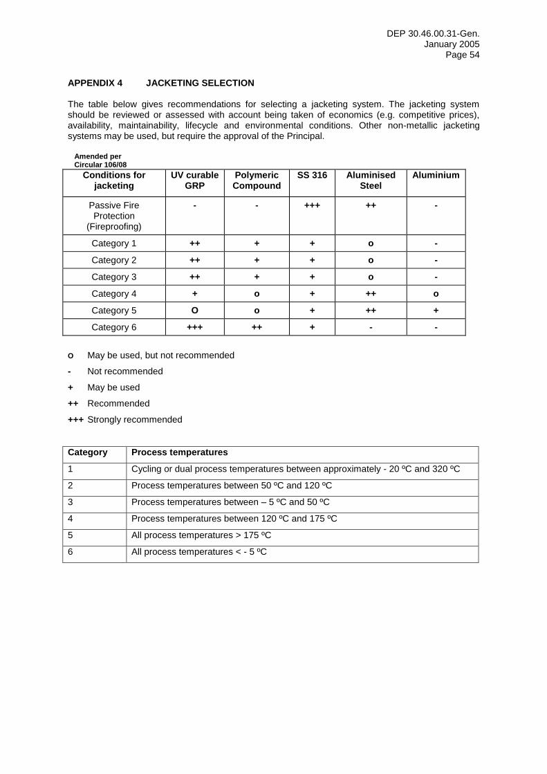
DEP 30.46.00.31-Gen. January 2005
Page 54
APPENDIX 4 JACKETING SELECTION
The table below gives recommendations for selecting a jacketing system. The jacketing system should be reviewed or assessed with account being taken of economics (e.g. competitive prices), availability, maintainability, lifecycle and environmental conditions. Other non-metallic jacketing systems may be used, but require the approval of the Principal.
Amended per Circular 106/08
Conditions for jacketing
UV curable GRP
Polymeric Compound
SS 316 Aluminised Steel
Aluminium
Passive Fire Protection
(Fireproofing)
- - +++ ++ -
Category 1 ++ + + o -
Category 2 ++ + + o -
Category 3 ++ + + o -
Category 4 + o + ++ o
Category 5 O o + ++ +
Category 6 +++ ++ + - -
O May be used, but not recommended
- Not recommended
+ May be used
++ Recommended
+++ Strongly recommended
Category Process temperatures
1 Cycling or dual process temperatures between approximately - 20 ºC and 320 ºC
2 Process temperatures between 50 ºC and 120 ºC
3 Process temperatures between – 5 ºC and 50 ºC
4 Process temperatures between 120 ºC and 175 ºC
5 All process temperatures > 175 ºC
6 All process temperatures < - 5 ºC

DEP 30.46.00.31-Gen. January 2005
Page 55
APPENDIX 5 INSPECTION OF THERMAL INSULATION SYSTEMS
Example of Thermal Insulation Inspection Survey
Check the following deficiencies/defects Tick box if applicable
Consequences
Caulking/Sealant that has hardened and separated
Circumferential cracks in GRE/GRP jacketing
Corrosion cladding
Damaged or loose cladding
Damaged vapour barrier/stop
Corrosion under insulation
Failure at bends (open joints)
Deterioration of insulation system
Foot traffic damage
Soaked insulation material
Gaps due to uncontrolled expansion/contraction Substandard
thermal performance
Hot/Cold Spots
Water ingress
Icing and/or condensation
Fungal growth
Longitudinal cracks in GRE/GRP jacketing
Ice formation and slippery areas
Missing insulation (not re-installed after shutdowns
Missing self-tapping screws, rivets or SS bands
Rust staining and bulges in metal cladding
Sagged insulation and cladding
No termination at flanges/valves
No termination in a vertical pipe or piece of equipment
Water ingress at penetrations (e.g. nozzles)
If any of the above deficiencies/defects have occurred, the extent or amount shall be reported to the static/mechanical inspection department and/or to the reliability/integrity department, so that they can take action and implement the information into their RBI module.
The next page gives guidance on the set up of an inspection record that is part of the reporting system.

DEP 30.46.00.31-Gen. January 2005
Page 56
Example of Thermal Insulation Inspection record
Insulation Inspection Record Description, Explanation and Input
Insulation Inspection ID Create Unique Number
Inspection Date Input date
Insulation Tag Number Line number or equipment number
Insulation Unit Number Process unit
Kind of Thermal Insulation Hot, Hot/Acoustic, Cold, Cold/Acoustic, PP and Others
Installed in Year Give year of installation
Drawing list Connected to Database file
Isometric number Connected to Auto Cad File or Database file
Operating Temperature Can be checked via supervisory systems or otherwise obtained.
Operation Mode Constant, Cycling temperatures, Ambient to 100 C, Ambient to 200 C, Ambient to
300 C and Minus to Ambient
Remarks on Operation E.g. long down time periods
Climate conditions Indicate climate conditions, e.g. marine and tropical (rainfall > 2000 mm) or marine and desert. This information is required assessing the corrosion rate if insulation and painting systems don’t give sufficient protection.
Local environmental conditions Indicate the local environmental conditions, such as:
- Areas exposed to mist over spray from cooling towers. - Areas exposed to steam vents. - Areas exposed to deluge systems. - Areas subject to process spills, ingress of moisture, or acid vapours.
Piping/Equipment material Carbon, low carbon steel or stainless steel, etc.
Insulation Material Rock Wool, PUR/PIR, Flexible Elastomeric Foam etc.
Description of Insulation System E.g. cold insulation of PUR and finished with mastic vapour barrier and stainless steel cladding.
Number of Damaged Penetrations Could be given per isometric drawing or could be indicated in the drawing.
Description of Damaged Penetrations
The nature of damage, e.g. failure of the sealant.
Cause of Damaged Penetrations Substandard Workmanship, Substandard Design, Ageing or Damaged by third party
Amount of Missing Cladding Metres lengths of pipe or m2
equipment per isometric.
Description of Missing Cladding Type of cladding, swages
Cause of Missing Cladding Substandard Workmanship, Substandard use, Substandard Design, Not re-installed during shutdown.
Number of Missing Terminations Indicate the amount per isometric
Description of Missing Terminations
Indicate what is missing, e.g. material not reinstalled after modifications etc.
Cause of Missing Terminations Substandard Workmanship, Substandard use, Substandard Design, Damaged by third part, Not re-installed during shutdown
Amount of Missing Valves/Flanges insulation
Indicate the amount per isometric
Description of Missing Valves/Flanges insulation
Indicate what is missing, e.g. material not reinstalled after modifications etc.
Cause of Missing Valves/Flanges insulation
Substandard Workmanship, Substandard use, Substandard Design, Damaged by Third Party
Description of Deficiencies/defects
Give a description as indicated in the lat page.
General Condition Insulation Good, Moderate and Substandard
Inspection Findings and Consequential Damage
Give your judgement regarding CUI, Thermal losses etc.,
Action required? Yes or No
If action is required, indicate when!
First opportunity, during shutdown, within 1 year or within 2 years, etc..
Inspection Sequence Every 6 months and/or after every shutdown
Next Inspection Date? Date or combined with mechanical inspection. Results will depend on the outcome of the RBI module.
Quantities and Cost of Replacement/Repairs
Indicate roughly the quantities and cost. The cost-estimating department should work out information.
Amount of total costs Indicate roughly

DEP 30.46.00.31-Gen. January 2005
Page 57
APPENDIX 6 PERSONNEL PROTECTION - GUARD DISTANCES AND INSULATION THICKNESS
For process temperatures from 70 C to 250 C barrier protections should be applied, without insulation (e.g. 60 % rigid perforated sheets or wire mesh, as indicated in Appendix 7).
For process temperatures > 250 C, rock wool with metal cladding is recommended.
Criteria for the table below are:
Ambient temperature: 25 C.
Wind velocity: 1 m/s.
Surface temperature protection: max. 70 C
NOTE: Criteria could be different for other locations and shall be determined/reviewed per location.
Table: Recommended distances between perforated metal sheet/guards and bare surface, and insulation thickness for personnel protection
Normal operating temperature (C)
70 to 250 > 250 350 400 450 500 600
Nominal pipe
diameter (DN)
Distance from sheet/guard to bare surface (mm)
Insulation thickness (mm)
< 25 50 25 30 40 40 50 60
25 50 25 30 40 40 50 60
40 50 25 30 40 50 60 70
50 50 25 40 40 50 60 70
80 50 30 40 40 50 60 80
100 50 30 40 50 50 70 80
150 50 30 40 50 60 70 80
200 50 30 40 50 60 80 80
250 50 30 40 50 60 80 100
300 100 30 40 50 60 80 100
350 100 30 40 50 70 80 100
400 100 30 40 50 70 80 100
450 100 30 40 50 70 80 100
500 100 40 40 50 70 80 100
Equipment Channels/Flat Surfaces
40 40 50 70 80 100

DEP 30.46.00.31-Gen. January 2005
Page 58
APPENDIX 7 PERSONNEL PROTECTION - PHYSICAL BARRIERS

DEP 30.46.00.31-Gen. January 2005
Page 59
APPENDIX 8 TYPICAL DETAILS OF SEALING PLATES AROUND NOZZLES (HOT INSULATION)

DEP 30.46.00.31-Gen. January 2005
Page 60
APPENDIX 9 INSULATION COLLAR SOLUTIONS (alternatives to Standard Drawing S10.056)
Figure 9 A Cellular glass around nozzle (hot insulation)

DEP 30.46.00.31-Gen. January 2005
Page 61
Figure 9 B Cellular glass around protrusion (hot insulation)

DEP 30.46.00.31-Gen. January 2005
Page 62
APPENDIX 10 REMOVABLE COVER FOR SPECTACLE BLIND FLANGE IN VERTICAL PIPE (HOT INSULATION)

DEP 30.46.00.31-Gen. January 2005
Page 63
APPENDIX 11 REMOVABLE COVER FOR SPECTACLE BLIND FLANGE IN HORIZONTAL PIPE (HOT INSULATION)

DEP 30.46.00.31-Gen. January 2005
Page 64
APPENDIX 12 REMOVABLE INSULATION COVER FOR PUMPS (HOT INSULATION)

DEP 30.46.00.31-Gen. January 2005
Page 65
APPENDIX 13 SUPPORT PINS FOR BLANKET INSULATION ON HORIZONTAL VESSELS (HOT INSULATION)

DEP 30.46.00.31-Gen. January 2005
Page 66
APPENDIX 14 DISPENSED PIR/PUR FOAM (COLD INSULATION

DEP 30.46.00.31-Gen. January 2005
Page 67
APPENDIX 15 PIPE SUPPORT - MULTI-LAYER (COLD INSULATION)

DEP 30.46.00.31-Gen. January 2005
Page 68
APPENDIX 16 CONTRACTION BELLOWS (COLD INSULATION)

DEP 30.46.00.31-Gen. January 2005
Page 69
APPENDIX 17 TYPICAL SECTION OF RUNDOWN LINE BETWEEN INTERMEDIATE ANCHORS (SLIDE THROUGH INSULATION SYSTEM)

DEP 30.46.00.31-Gen. January 2005
Page 70
APPENDIX 18 PRE-INSULATION OF PIPE LENGTH - SHEAR KEY SYSTEM –

DEP 30.46.00.31-Gen. January 2005
Page 71
APPENDIX 19 SHEAR KEY DETAILS

DEP 30.46.00.31-Gen. January 2005
Page 72
APPENDIX 20 PRE-INSULATION OF PIPE LENGTH - SLIDE THROUGH SYSTEM

DEP 30.46.00.31-Gen. January 2005
Page 73
APPENDIX 21 LONGITUDINAL SECTION THROUGH RUNDOWN LINE AND PRIMARY GUIDE

DEP 30.46.00.31-Gen. January 2005
Page 74
APPENDIX 22 PRIMARY GUIDE SYSTEM - TYPICAL EXAMPLE

DEP 30.46.00.31-Gen. January 2005
Page 75
APPENDIX 23 PRE INSULATION OF PIPE LENGTH - SLIDE THROUGH SYSTEM

DEP 30.46.00.31-Gen. January 2005
Page 76
APPENDIX 24 ALTERNATIVE TO CINI 5.2.06 INSULATION DETAIL VACUUM/SUPPORT RING – CONTRACTION JOINT (only to be used if vacuum/support rings are not installed)

DEP 30.46.00.31-Gen. January 2005
Page 77
APPENDIX 25 ALTERNATIVE TO CINI 5.9.01 MECHANICAL ENGINEERING DETAIL LUGS/SUPPORT STRIP ON COLUMNS/SKIRTS (only to be used if lugs/support strips are not installed)

DEP 30.46.00.31-Gen. January 2005
Page 78
Last page of this DEP
APPENDIX 26 INSULATION COLLAR FOR PROTECTION AGAINST FLAMMABLE PRODUCTS


![Logic Programming in ClojureDependency Graph Nodes (def doe (ref {:name “doe”:last-update (Date.):deps [rae fa sew]})) (def rae (ref {:name “rae”:last-update (Date.):deps [fa]}))](https://static.fdocuments.us/doc/165x107/5f775adacd82e475b70c7c10/logic-programming-in-clojure-dependency-graph-nodes-def-doe-ref-name-aoedoealast-update.jpg)