Thermal Imaging Test Target THERMAKIN …OFFICIAL 9 OFFICIAL 2. Principles The Thermakin test target...
21
OFFICIAL 1 OFFICIAL Thermal Imaging Test Target – THERMAKIN Manufacture and Test Standard June 2014 This document has been produced by CPNI as the standard for the physical design, manufacture and method of use of the Thermal Imaging Test Target – THERMAKIN. Disclaimer: Reference to any specific commercial product, process or service by trade name, trademark, manufacturer, or otherwise, does not constitute or imply its endorsement, recommendation, or favouring by CPNI. The views and opinions of authors expressed within this document shall not be used for advertising or product endorsement purposes. To the fullest extent permitted by law, CPNI accepts no liability for any loss or damage (whether direct, indirect or consequential and including, but not limited to, loss of profits or anticipated profits, loss of data, business or goodwill) incurred by any person and howsoever caused arising from or connected with any error or omission in this document or from any person acting, omitting to act or refraining from acting upon, or otherwise using, the information contained in this document or its references. You should make your own judgement as regards use of this document and seek independent professional advice on your particular circumstances. The text of this publication may not be reproduced, nor may talks or lectures based on material contained within the document be given, without written consent from the Centre for the Protection of National Infrastructure (CPNI). © Crown Copyright 2014
Transcript of Thermal Imaging Test Target THERMAKIN …OFFICIAL 9 OFFICIAL 2. Principles The Thermakin test target...

OFFICIAL
1 OFFICIAL
Thermal Imaging Test Target – THERMAKIN
Manufacture and Test Standard
June 2014
This document has been produced by CPNI as the standard for the physical design, manufacture and method of use of the Thermal Imaging Test Target – THERMAKIN.
Disclaimer: Reference to any specific commercial product, process or service by trade name, trademark, manufacturer, or otherwise, does not constitute or imply its endorsement, recommendation, or favouring by CPNI. The views and opinions of authors expressed within this document shall not be used for advertising or product endorsement purposes. To the fullest extent permitted by law, CPNI accepts no liability for any loss or damage (whether direct, indirect or consequential and including, but not limited to, loss of profits or anticipated profits, loss of data, business or goodwill) incurred by any person and howsoever caused arising from or connected with any error or omission in this document or from any person acting, omitting to act or refraining from acting upon, or otherwise using, the information contained in this document or its references. You should make your own judgement as regards use of this document and seek independent professional advice on your particular circumstances. The text of this publication may not be reproduced, nor may talks or lectures based on material contained within the document be given, without written consent from the Centre for the Protection of National Infrastructure (CPNI).
© Crown Copyright 2014

<OFFICIAL
2 OFFICIAL
Document history
Version Purpose Originated Reviewed Reviewed Date
1.0 First Publication AP CPNI June 14
Any comments or suggestions regarding this document should be directed to: K1B-13 – Inner Envelope Central Support – Outer Envelope PO Box 60628 London SW1P 9HA
Correspondence to this address must be under double cover. The outer envelope should be addressed to: Central Support, PO Box 60628, London SW1P 9HA and not to any individual.

<OFFICIAL
3 OFFICIAL
Executive Summary
This standard gives details of how to manufacture Thermakin to the correct specification for testing a thermal imaging system used for intrusion detection. It gives a brief outline and the background into the history of thermal imaging cameras and explains:
a) The reason for testing at the temperatures stated
b) The reason for production of the test target.
It contains visual representations of expected results at the respective screen heights and detailed drawings for manufacturing.

<OFFICIAL
4 OFFICIAL
1. Introduction
Thermal imaging systems were developed from the end of the Second World War. The technology developed incrementally for a time but during the mid to late 1980s onwards, with the development of un-cooled staring focal plane arrays, growth and uptake have increased rapidly. Thermal imagers are now predicted to halve in cost and treble in the number of units sold per annum in the next five years. For all sectors the current status and predicted future trends in thermal imaging technology are having a significant impact on use and uptake. For the security sector, there has been an increased use of thermal imagers (TI) as part of integrated perimeter security, for both detection and verification. However, as with many other sectors, the rapid development of thermal imaging technology has meant that currently there is no standardised method for testing the end-to-end performance of a TI system. Thermakin is a thermal imagery test target simulating a pedestrian sized threat. It is a simple, robust and fit for use panel providing a thermal contrast tool for the assessment of thermal imaging systems. It covers the operational conditions experienced in the UK, and is equivalent to the Rotakin system for CCTV. The target operates entirely passively (i.e. no heating) and uses surface reflectivity and geometry to provide the required thermal contrast of apparent cold and apparent heat, whilst remaining entirely at ambient temperature. This CPNI standard is published to enable users to manufacture a passive test target to test thermal imaging cameras used for their security systems for intrusion detection This standard references requirements from the appropriate British standards and uses technical specifications for the Rotakin (visible band) standard test target.
Thermal imaging Thermal imaging is the capture (through optics) and detection of Infrared radiation. Infrared thermal imaging systems typically use detector arrays (staring focal plane arrays) to provide a thermal image. Thermal imaging systems have been in existence for over 50 years but have only become widely adopted over the last decade – this growth in adoption is due to improved performance, reduced costs and improved practicality.
Key Point – Thermal imagers use infrared radiation to operate.
<OFFICIAL
5 OFFICIAL
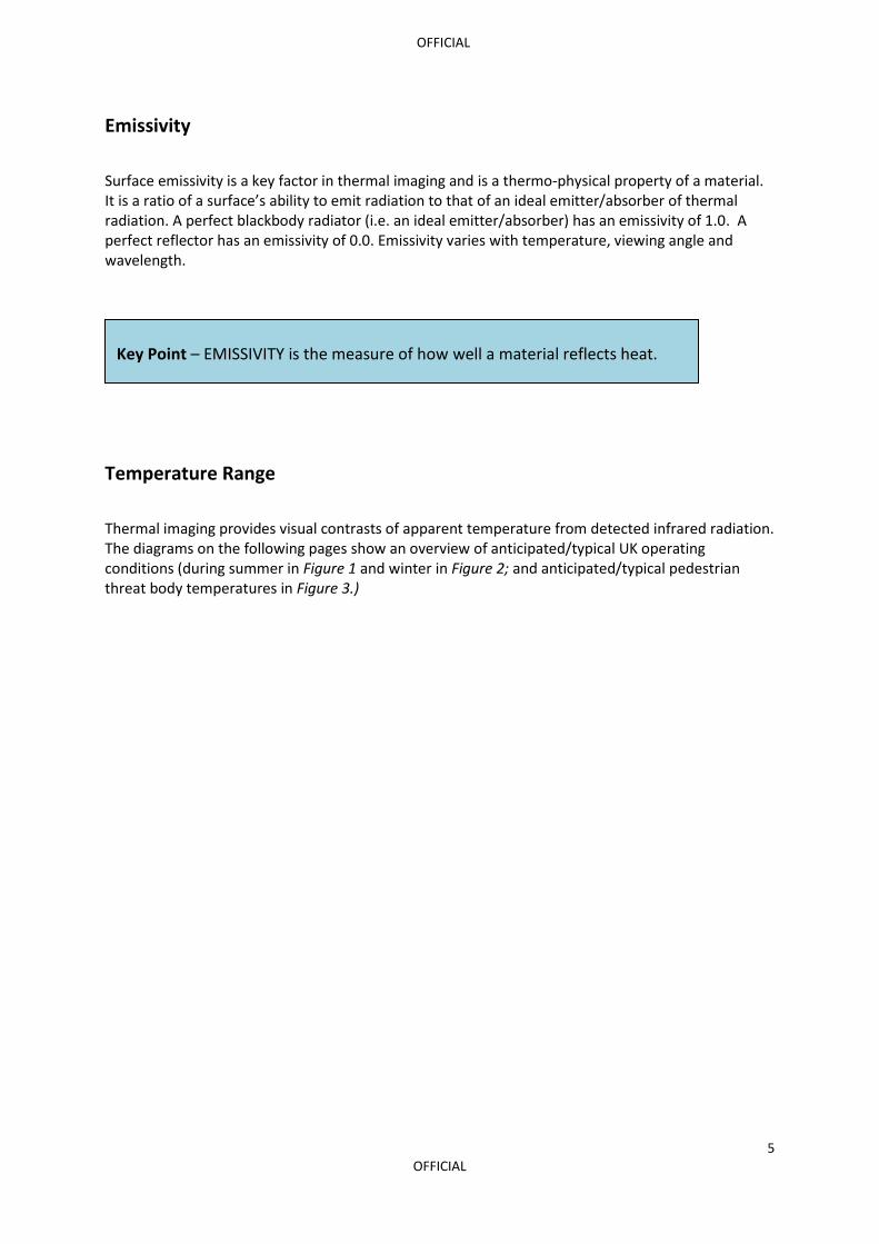
Emissivity
Surface emissivity is a key factor in thermal imaging and is a thermo-physical property of a material. It is a ratio of a surface’s ability to emit radiation to that of an ideal emitter/absorber of thermal radiation. A perfect blackbody radiator (i.e. an ideal emitter/absorber) has an emissivity of 1.0. A perfect reflector has an emissivity of 0.0. Emissivity varies with temperature, viewing angle and wavelength.
Temperature Range
Thermal imaging provides visual contrasts of apparent temperature from detected infrared radiation. The diagrams on the following pages show an overview of anticipated/typical UK operating conditions (during summer in Figure 1 and winter in Figure 2; and anticipated/typical pedestrian threat body temperatures in Figure 3.)
Key Point – EMISSIVITY is the measure of how well a material reflects heat.

<OFFICIAL
6 OFFICIAL
Figure 1: A map of the mean maximum temperature, summer average for the United Kingdom (UK).

<OFFICIAL
7 OFFICIAL
Figure 2: A map of the mean minimum temperature, winter average for the United Kingdom (UK).

<OFFICIAL
8 OFFICIAL
Figure 3: Medical thermography, image of hands
The medical thermography image (Figure 3) uses standardised temperature bar scaling for medical use (i.e. 17°C to 36°C). This is a typical maximum and minimum range and fundamentally relates to bare skin measurement. These operating temperatures are those expected within the UK in summertime. In winter time there would be less of a problem matching the outside temperature to the temperature of the human body. Thermakin is not a heated target but instead uses reflected sky vs. ambient temperature to produce thermal contrast. Marketing literature may show vehicle temperatures of several hundred degrees in an environment which has an ambient temperature in the negative range, this is not realistic within the UK and it is not representative of what can be expected. As can be seen from the weather charts above and Fig 3 of the human body, a 30 degree variation is more realistic, therefor Thermakin has been designed to represent this thermal differential.

<OFFICIAL
9 OFFICIAL
2. Principles
The Thermakin test target is a panel simulating a silhouette of a person and is illustrated in Figure 6. The main body of the target is flat and has a high emissivity surface normal to the line of sight of the thermal imager under test. This emits ambient temperature infrared radiation (nominally), in this case ‘apparent warmth’. Horizontally across the main body are several strips of right angled aluminium, 50mm wide, with different lengths to provide the required resolution targets. These bare aluminium surfaces, which provide a low emissivity surface, are angled to upward in order to reflect the sky temperature infrared radiation (nominally), in this case ‘apparent cool’. In combination these two surfaces provide the pedestrian sized threat and a thermal contrast for thermal imagery system assessment. The target is designed to be inexpensive to produce, portable, easy to install, very low maintenance and unpowered. The test target must represent an appropriate target size for pedestrian threats and should set the minimum detectable screen height for an operator. The target needs to be indicative of humans, in all weathers, seasons and clothing and physical condition. The sensors are to be used for human detection and verification, not for identification. The target was tested with low and high resolution uncooled thermal imaging systems.
3. Build Specification
Thermakin body
The Thermakin is constructed from 12mm plywood, made in two equal halves (same dimensions) and coated in matt black paint. An aluminium square tube section runs the length of the back of both sections to join and link into a standard Rotakin mounting tripod (one should verify the compatibility and joining of linkages during construction). The drawings for the two halves are shown in figures 4 and 5.
Key Principle – The target is passive. It works by using two different surface emissivities (and geometry) and provides a pedestrian sized threat with thermal contrast representative of the environment it is working in.

<OFFICIAL
10 OFFICIAL
Figure 4: Top section drawing

<OFFICIAL
11 OFFICIAL
Figure 5: Bottom section drawing

<OFFICIAL
12 OFFICIAL
Resolution bars There are eight resolution bars. These are constructed from 50mm right angled aluminium sections and sized so as to be comparable to those used with Rotakin. Each section is fitted to the ply such that one face is angled toward the sky and one is angled toward the ground. The sky angled face has five resolution strips on its face being bare/painted/bare/painted/bare. The ground angled face is painted. C: 400 TVL/PH 40 mm in total length 8.0 mm strips D: 350 TVL/PH 45.5 mm in total length 9.1 mm strips E: 300 TVL/PH 50.5 mm in total length 10.1 mm strips F: 250 TVL/PH 64.0 mm in total length 12.8 mm strips G: 200 TVL/PH 80.0 mm in total length 16.0 mm strips H: 150 TVL/PH 106.5 mm in total length 21.3 mm strips J: 100 TVL/PH 160.0 mm in total length 32.0 mm strips K: 80 TVL/PH 200 mm in total length 40.0 mm strips
Figure 6: Thermakin resolutions
H
F
G
C
K
D
E
J

<OFFICIAL
13 OFFICIAL
4. Screen percentage
The target shall be used for the specification, commissioning and maintenance of the thermal imaging systems and their assessment versus an operational requirement. The Thermakin was tested at the following percentages 100%, 50%, 25% and 10% and at resolutions 160 x 120 & 320 x 240. Images of what you should expect to see on a TI camera and a visible camera are shown in figures 7 - 14. The percentage screen heights were chosen for comparison to ‘normal’ CCTV. 100%, 50% and 10% are stated as the required screen heights for identification, recognition and detection respectively. The ability of the system to provide a suitable size of image anywhere in the area to be covered can be tested using Thermakin. The figures for image height assume that the size of the picture monitor screen, observer viewing distance and observation conditions do not themselves limit the system performance. For comparison, ‘normal’ images are shown in figures 14 – 18 at the same screen heights.
Key Point – Although tested throughout the whole range of screen heights, CPNI recommend thermal imaging cameras should not be used for anything other than detection – (10% Screen height). This is because detail cannot be seen on a TI image. It is not possible to gain any other information other than identifying a human, animal, etc.

<OFFICIAL
14 OFFICIAL
Figure 7: Thermakin @ 100% (Thermal) 160 x 120
Figure 8: Thermakin @ 100% (Thermal) 320 x 240

<OFFICIAL
15 OFFICIAL
Figure 9: Thermakin @ 50% (Thermal) 160 x 120
Figure 10: Thermakin @ 50% (Thermal) 320 x

<OFFICIAL
16 OFFICIAL
Figure 11: Thermakin @ 25% (Thermal) 160 x 120
Figure 12: Thermakin @ 25% (Thermal) 320 x 240

<OFFICIAL
17 OFFICIAL
Figure 13: Thermakin @ 10% (Thermal) 160 x 120
Figure 14: Thermakin @ 10% (Thermal) 320 x 240

<OFFICIAL
18 OFFICIAL
Figure 15: 100% Visible Picture
Figure 16: 50% Visible Picture

<OFFICIAL
19 OFFICIAL
Figure 17: 25% Visible Picture
Figure 18: 10% Visible Picture

<OFFICIAL
20 OFFICIAL
5. Test Procedure
Aim
To confirm that camera coverage and returned image meet the operational requirement.
Method
Place Thermakin at strategic points within the area of coverage as defined by the operational requirement and system specification. Establish the detectability at specific percentage screen heights at each strategic point. The tests should be carried out over the total light and temperature ranges that the system will be expected to operate under. Other environmental conditions should also be considered when testing a TI camera, for example, fog, snow and rain.
Image Height
The image heights should be recorded as a percentage of screen vertical height. It should be confirmed that these figures comply with the operational requirement. Examples of expected images can be seen in figures 7 – 18, both as TI images and as standard CCTV images.
Contrast
An image of the view containing the Thermakin is presented to the operator and the image contrast is evaluated using the vertical and horizontal bars. This test should be repeated for various positions and the results recorded. Note should be made of the appearance of the target on the monitor. It should be described in terms of: VERY CLEAR CLEAR INDISTINCT NOT DISCERNABLE.
Alignment
Once constructed the target should be nominally vertical. The target should then be positioned such that the front face of the target is normal (at right angles) to the line of sight of the thermal imaging camera under test i.e. so that the target front face can be imaged by the thermal imaging camera.
Figure 1

<OFFICIAL
21 OFFICIAL
Related Documentation
CPNI Guide to preparing Operational Requirements CPNI Thermal Imager Guidance CPNI Surveillance Thermal Imager Document CPNI CCTV for CNI Perimeter Security