Thermal-Hydraulic Analysis of Seismically-Induced Loss of ...
25
www.inl.gov Thermal-Hydraulic Analysis of Seismically-Induced Loss of Coolant Accidents Involving Double Ended Guillotine Breaks in the Inpile Tubes at the Advanced Test Reactor IRUG User Presentations Gable Roth Nuclear Safety Analyst Idaho National Laboratory October 6, 2016
Transcript of Thermal-Hydraulic Analysis of Seismically-Induced Loss of ...

ww
w.in
l.gov
Thermal-Hydraulic Analysis of Seismically-Induced Loss of Coolant Accidents Involving Double Ended Guillotine Breaks in the Inpile Tubes at the Advanced Test Reactor
IRUG User Presentations
Gable Roth Nuclear Safety Analyst
Idaho National Laboratory
October 6, 2016

Objectives • ATR Overview • ATR Primary Coolant System Design • ATR Experiment Loop Design • Details of RELAP use • Previous analysis • Updated analysis • Conclusions
2

Reactor Description Reactor Type • Pressurized, light-water
moderated and cooled; beryllium reflector
• 250 MWt (Full Power)
Reactor Vessel • 12 ft (3.65 m) diameter cylinder • 36 ft (10.67 m) high stainless
steel Reactor Core • 4 ft (1.22 m) diameter and height • 40 fuel elements, curved-plate,
aluminum-clad metallic U-235 • Highly enriched uranium matrix
(UAlx) in an aluminum sandwich plate cladding
3

Operating Conditions Power (MWth)
Power density (kW/ft3) PCS pressure (psig)
Inlet/Outlet temp. (°F) PCS flow rate (gpm) Coolant mass (lbm)
Coolant mass/power ratio (lbm/MW) Decay heat (MW @ 10s, 1 day)
Fuel enrichment (% 235U) Fuel mass (lbm) Fuel temp. (°F)
Fission-product inventory
ATR Operating Condition Comparison to PWR
4
ATR 250
28,000 355
125/170 48,000 600,000 2,400 13, 1.3
93 90 460 --
PWR (typ.) 2,000 – 4,000
1,550 2,250
550/600 300,000 450,000
170 135, 19 2 – 4
180,000 2,000 – 3,000
10 × ATR

ATR Core Cross Section, Test Positions
• Test size - up to 5.0” Dia. • 77 irradiation positions:
- 3 open flux traps - 6 inpile tubes - 68 positions in reflector
• Approximate Peak Flux: - 1 x 10¹⁵ n/cm2-sec
thermal - 5 x 10¹⁴ n/cm2-sec fast
• Hafnium Control Drums - Flux/power adjustable
across core - Maintains axial flux
shape
5
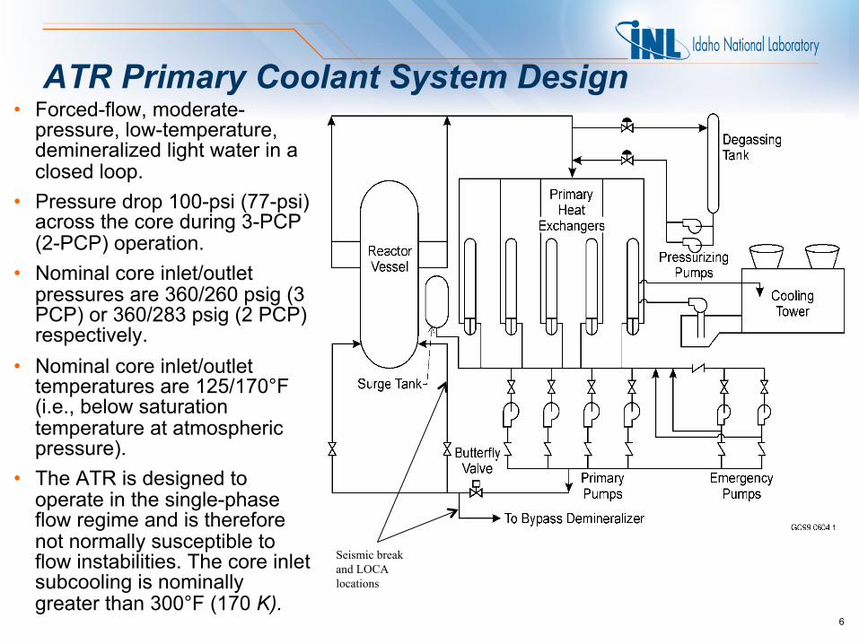
ATR Primary Coolant System Design • Forced-flow, moderate-
pressure, low-temperature, demineralized light water in a closed loop.
• Pressure drop 100-psi (77-psi) across the core during 3-PCP (2-PCP) operation.
• Nominal core inlet/outlet pressures are 360/260 psig (3 PCP) or 360/283 psig (2 PCP) respectively.
• Nominal core inlet/outlet temperatures are 125/170°F (i.e., below saturation temperature at atmospheric pressure).
• The ATR is designed to operate in the single-phase flow regime and is therefore not normally susceptible to flow instabilities. The core inlet subcooling is nominally greater than 300°F (170 K).
Seismic break and LOCA locations
6

ATR Experiment Loop Design
flow elements
flow-control valve
temperature- control valve
heat exchanger mixing
tee
pressurizer
heater leg (x5)
loop coolant pumps
line heaters
strainer
80 gpm; 650°F; 2500 psig
Seismic break and LOCA location
Inpile tube
7

ATR Standard Inpile Tube (SIPT) Design
8

PCS LOCA Thermal-Hydraulic Analysis Summary • Condition 4 fault, an earthquake
was assumed to cause a 1-in. reactor inlet break, a 2.5-in. rupture of the bypass demineralizer inlet line.
• Overall response of the reactor was calculated with the RELAP5 code, and core safety margins were calculated with the ATR-SINDA and SINDA-SAMPLE fuel plate models.
• Core power, top-of-core pressure, core pressure drop, and hot channel inlet and outlet enthalpy as functions of time were obtained from RELAP5 for input into SINDA and SINDA-SAMPLE.
• RELAP5 determines the “hot fuel element” of the 40 fuel elements.
9

PCS LOCA Thermal-Hydraulic Analysis Summary
10
• The ATR-SINDA fuel plate model computes the temperature distributions in any of the 19 fuel plates of the “hot” ATR fuel element as determined from RELAP5.
• ATR-SINDA determines the limiting fuel plate (of the 19 fuel plates) in the hot fuel element.
• ATR-SINDA simulates one-half of the fuel plate (azimuthally) and a portion of the adjoining side plate.
• The SINDA-SAMPLE model computes the various safety margins using a statistical approach.

RELAP • RELAP5 Mod 2.5 and Mod 3 • Support ATR Safety Analysis • Used in conjunction with ATR-SINDA and SINDA-SAMPLE
– ATR-SINDA is used to calculate the thermal-hydraulic response of the limiting subchannel, called the hot stripe, adjacent to the limiting fuel plate and to perform multi-dimensional heat transfer calculations
– SINDA-SAMPLE is used to compute the thermal safety margins for the limiting subchannel of the limiting fuel plate using a statistical approach
• Different accidents analyzed include – Loss of Coolant Accident (LOCA) – Loss of Commercial Power – Reactivity Insertion Accidents
11

Previous Seismic LOCA Analysis • Determine the effects of seismic breaks and leakage in the Advanced
Test Reactor (ATR) experiment loop piping
• Limiting break was a double ended offset shear of a ½ inch pipe in the drain manifold at the heater legs
• Two loss of commercial power accidents were analyzed:
– 4.0$ void worth and 9.6$ safety rod worth
– 5.0$ void worth and 12.0$ safety rod worth
12

Previous Method of Analysis • Focused analysis on “early” and “late” phase of the transient
– Early: 1 to 150 seconds (Worst Case) – Late: 1800 to 2100 seconds
13

Previous Analysis Results
14
Case Minimum Safety Margin
CHF (σ) FI (σ)
4.0$ void worth/9.6$ safety rod worth LOCA w/bounding sensitivity case
3.34 2.72
5.0$ void worth/12.0$ safety rod worth LOCA w/bounding sensitivity case
3.52 3.75
Safety Margin Summary

Updated Analysis • Previous Analysis neglected to take into account how the heat from the
loops affected the reactivity insertion
• Analyzed a different break location to support worst case for pressurizer collapse
• Sensitivity study indicated that the 4.0$ case is more limiting
• Early phase was selected as the most limiting
• Minimal additional changes
15

IPT Breaks
flow elements
flow-control valve
temperature- control valve
heat exchanger mixing
tee
pressurizer
heater leg (x5)
loop coolant pumps
line heaters
strainer
80 gpm; 650°F; 2500 psig
Inpile tube
16
Seismic break and LOCA location
Previous break and LOCA location

ATR Primary Coolant System Design
Seismic break and LOCA locations
17

Method of Analysis • 0.0 to 2.0 seconds was a null transient
• RELAP5 Mod 3 was used to get reactivity insertion information from the loops which was then used in Mod 2.5
• Used a restart deck
• 3% Power Addition
• Compared loop blowdowns with reactivity step insertions
• All loops are assumed to fail; total void worth of all loops is either 4.0$ or 5.0$
• Results from Mod 2.5 were run through ATR-SINDA and SINDA‑SAMPLE
• Also analyzed Condition 2 and Condition 3 events 18

3% Addition Condition 4 • Analysis supports a 3% Effective Plate Power increase for ATR
analysis
• This is done in the ATR-SINDA deck by multiplying the power by 1.03
19
Case Minimum Safety Margin
CHF (σ) FI (σ)
4.0$ void worth/9.6$ safety rod worth LOCA w/bounding sensitivity case
3.34 2.72
4.0$ with 3% Addition 3.32 2.37
4.0$ Updated Analysis also with 3% addition 3.27 1.62

4.0$ Condition 4 Step Insertion
20
Case Minimum Safety Margin
CHF (σ) FI (σ)
4.0$ No Step 3.27 1.62
4.0$ Step 3.27 1.61

Updated Analysis Results
21
Case Minimum Safety Margin
CHF (σ) FI (σ)
Condition 2 6.98 12.80
Condition 3 6.25 9.25
5.0$ Condition 4 3.34 2.84
Condition 4 Step 3.27 1.61
Safety Margin Summary
Previously accepted FI margin 1.64 Fuel melt is still unlikely

CHF Plots
22

FI Plots
23

Conclusions • Original analysis neglected to include reactivity insertion contribution
from loops • Analyzed step insertion with 3% power increase and a new break
location • Safety margins lower than before but still acceptable
24

Questions?
25