THERMAL EXPANSION - University Courses in...
30
THERMAL EXPANSION Buckled rails due to thermal expansion and insufficient allowance between the rail tracks. S. O. Kasap University of Saskatchewan CANADA An e-Booklet Optimized for laser printing v.1.2 1990-2002 S.O. Kasap
Transcript of THERMAL EXPANSION - University Courses in...

THERMAL EXPANSION
Buckled rails due to thermal expansion
and insufficient allowance between the rail tracks.
S. O. KasapUniversity of Saskatchewan
CANADA
An e-BookletOptimized for laser printing
v.1.2 1990-2002 S.O. Kasap

Thermal Expansion ( S.O. Kasap, 1990 - 2001: v.1.2) 2An e-Booklet
CONTENTS
1. The Origin of Thermal Expansion
1.1. Example: Volume expansion coefficient
1.2. Example: Grüneisen's law
2. Temperature Dependence of Thermal Expansion Coefficient
2.1. Example: Grüneisen's law for diamond
3. Thermal Stresses
3.1. Example: A composite body with two constrained components in series
4. Differential Thermal Expansion
4.1. Example: A composite body subject to a temperature change
4.2. Example: A thin semiconductor film on a substrate
4.3. Example: Thermal failure of soldered joints
ADDITIONAL TOPICS
5. Grüneisen’s Law
APPENDIX I
6. Bulk Modulus and the Potential Energy Curve
NOTATION
USEFUL DEFINITIONS
The space shuttle Columbia successfully returns to land after completing itssecond mission in outer space. Materials used on the body of the spacecraft,especially in the nose region, have to withstand extremes of temperaturechanges without fracturing (courtesy of NASA).
Thermal Expansion ( S.O. Kasap, 1990 - 2001: v.1.2) 3An e-Booklet
THERMAL EXPANSION
“The idea that heat is some kind of internal motion of a material body,and not a special substance as Black1 and others thought, occurredfirst to a professional soldier [Benjamin Thompson2] and wassubstantiated by experiments carried out in a gun factory.”
George GamowBiography of Physics (Harper Brothers, New York, 1961)
1. The Origin of Thermal Expansion
For simplicity we will consider the bonding between only two atoms and examine the effect of temperatureon the average separation between the atoms.
Interatomic separation, r0
Uo
ro
BC
KE
U(r) = PE
BC
rav
T2
T1
Umin
A
A
Umin = –Uo
Energy
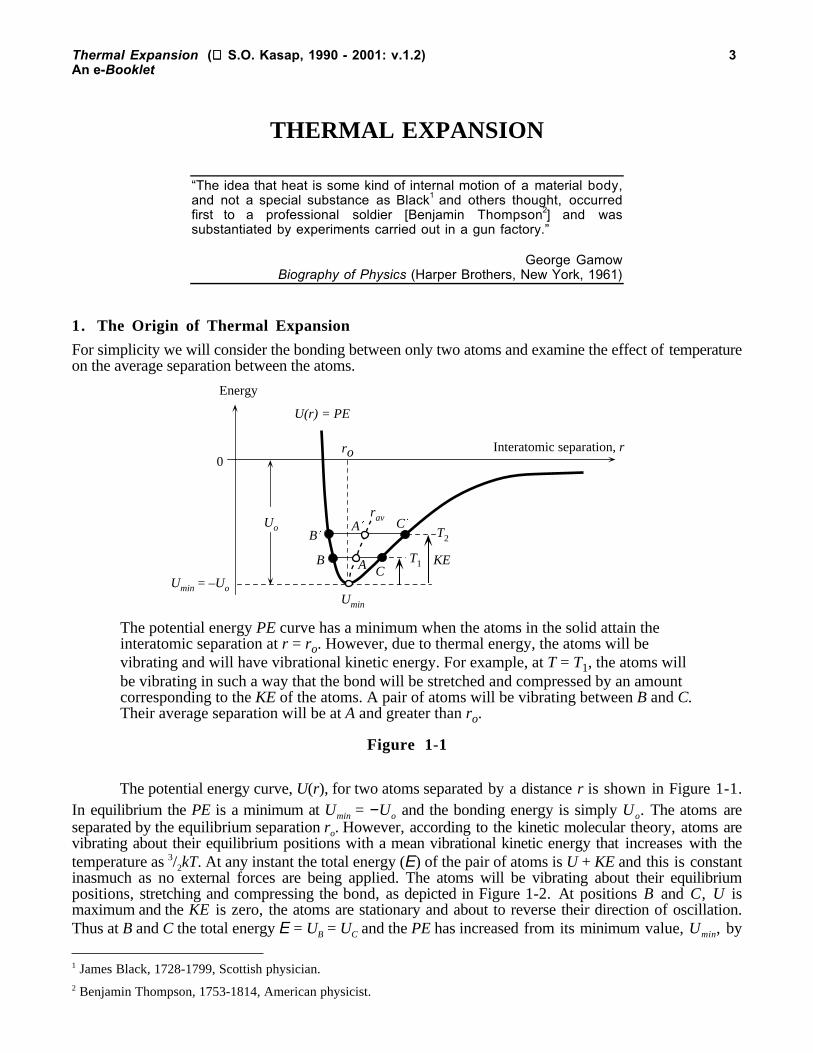
The potential energy PE curve has a minimum when the atoms in the solid attain theinteratomic separation at r = ro. However, due to thermal energy, the atoms will bevibrating and will have vibrational kinetic energy. For example, at T = T1, the atoms willbe vibrating in such a way that the bond will be stretched and compressed by an amountcorresponding to the KE of the atoms. A pair of atoms will be vibrating between B and C.Their average separation will be at A and greater than ro.
Figure 1-1
The potential energy curve, U(r), for two atoms separated by a distance r is shown in Figure 1-1.In equilibrium the PE is a minimum at Umin = −Uo and the bonding energy is simply Uo. The atoms areseparated by the equilibrium separation ro. However, according to the kinetic molecular theory, atoms arevibrating about their equilibrium positions with a mean vibrational kinetic energy that increases with thetemperature as 3/2kT. At any instant the total energy (E) of the pair of atoms is U + KE and this is constantinasmuch as no external forces are being applied. The atoms will be vibrating about their equilibriumpositions, stretching and compressing the bond, as depicted in Figure 1-2. At positions B and C, U ismaximum and the KE is zero, the atoms are stationary and about to reverse their direction of oscillation.Thus at B and C the total energy E = UB = UC and the PE has increased from its minimum value, Umin, by
1 James Black, 1728-1799, Scottish physician.2 Benjamin Thompson, 1753-1814, American physicist.
Thermal Expansion ( S.O. Kasap, 1990 - 2001: v.1.2) 4An e-Booklet
an amount equal to KE. The line BC corresponds to the total energy E. The atoms are confined to vibratebetween B and C, executing simple harmonic motion and hence maintaining E = U + KE = constant.
But the PE curve, U(r), is asymmetric. U(r) is broader in the r > ro region. Thus the atoms spendmore time in the r > ro region, that is, more time stretching the bond than compressing the bond (withrespect to the equilibrium length ro). The average separation corresponds to point A, i.e.
rav = 1/2(rB + rC)
which is clearly greater than ro. As the temperature increases, KE increases, the total energy E increasesand the atoms vibrate between wider extremes of the U(r) curve, between B′ and C′. The new average
separation at A′ is now greater than that at A: rA′ > rA. Thus as the temperature increases, the averageseparation between the atoms also increases which leads to the phenomenon of thermal expansion. If thePE curve were symmetric, than there would be no thermal expansion as the atoms would spend equaltimes in r < ro and r > ro regions.
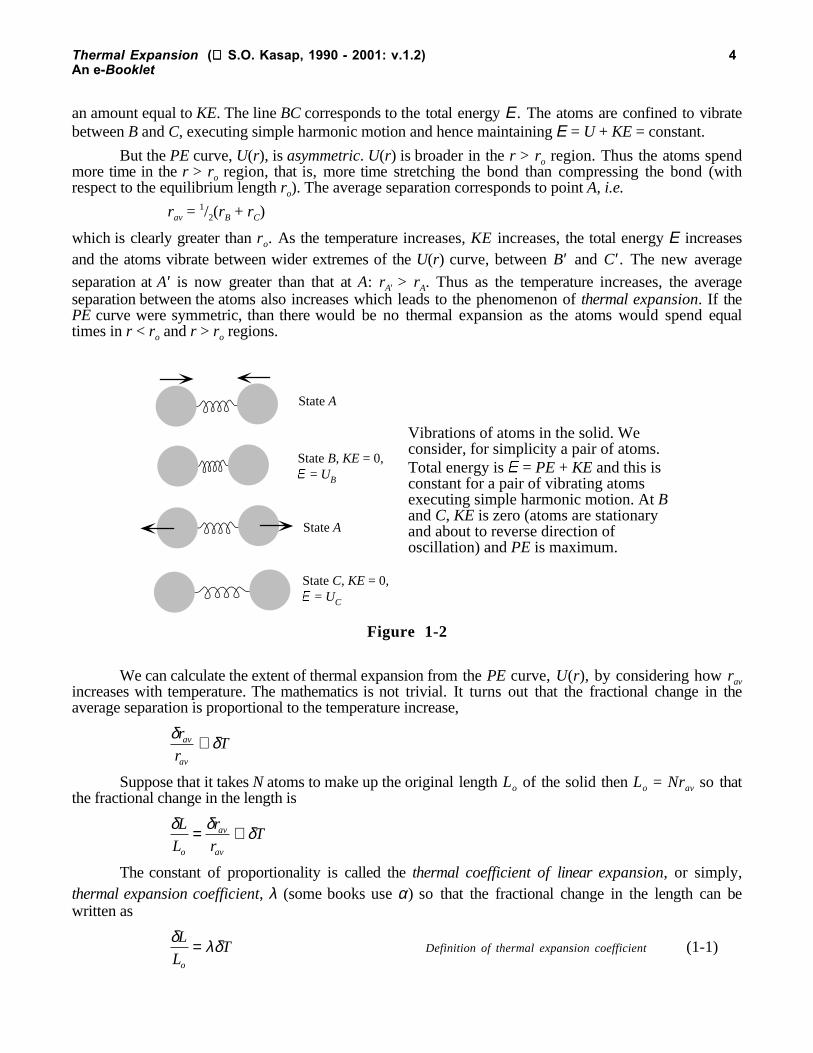
State A
State B, KE = 0, = UB
State A
State C, KE = 0, = UC
Vibrations of atoms in the solid. Weconsider, for simplicity a pair of atoms.Total energy is = PE + KE and this isconstant for a pair of vibrating atomsexecuting simple harmonic motion. At Band C, KE is zero (atoms are stationaryand about to reverse direction ofoscillation) and PE is maximum.
Figure 1-2
We can calculate the extent of thermal expansion from the PE curve, U(r), by considering how ravincreases with temperature. The mathematics is not trivial. It turns out that the fractional change in theaverage separation is proportional to the temperature increase,
δ δr
rTav
av
∝
Suppose that it takes N atoms to make up the original length Lo of the solid then Lo = Nrav so thatthe fractional change in the length is
δ δ δL
L
r
rT
o
av
av
= ∝
The constant of proportionality is called the thermal coefficient of linear expansion, or simply,thermal expansion coefficient, λ (some books use α) so that the fractional change in the length can bewritten as
δ λδL
LT
o
= Definition of thermal expansion coefficient (1-1)

Thermal Expansion ( S.O. Kasap, 1990 - 2001: v.1.2) 5An e-Booklet
Integrating this equation from Lo to L and assuming that λ is constant (independent of temperature)we find
L = Lo[1 + λ(T − To)] Thermal expansion (1-2)
We note that λ, coefficient of thermal expansion, is a material property that depends on the natureof the bond. The variation of rav with T in Figure 1-1 depends on the shape of the PE curve U(r).Generally, λ is larger for metallic bonding than for covalent bonding; there are, of course, alwaysexceptions.
Since the linear expansion coefficient λ is related to shape of the PE curve, U(r), it is also related to
the elastic modulus, E. Further λ also depends on the amount of increase from BC to B′C′ per degree of
increase in the temperature. λ must therefore also depend on the heat capacity. When the temperature
increases by a small amount, δT, the energy per atom increases by (CvδT)/N where Cv is the heat capacity
per unit volume and N is the number of atoms per unit volume. If CvδT is large then the line B′C′ in Figure
1-1 will be higher up on the energy curve and the average separation A′ will therefore be larger. Thus, the
larger is the heat capacity, the greater is the interatomic separation which means λ ∝ Cv. Further, theaverage separation, point A, depends on how much the bonds are stretched and compressed. For largeamounts of displacement from equilibrium, the average A will be greater as more asymmetry of the PEcurve is used. Thus smaller is the elastic modulus E the greater is λ.
If we were to expand U(r) about its minimum value Umin at r = ro we would obtain the Taylorexpansion,
U(r) = Umin + a2 (r − ro)2 + a3 (r − ro)
3 + ... (1-3)
where a2 and a3 are coefficients related to second and third derivatives of U at ro. The term (r−ro) is
missing because we are expanding a series about Umin where dU / dr = 0. The Umin and a2(r−ro)2 terms give
a parabola about Umin which is a symmetric curve around ro and therefore does not lead to thermalexpansion. Average location at any energy on a symmetric curve at ro is always at ro. It is the a3 term thatgives the expansion because it leads to asymmetry. Thus the amount of expansion λ also depends on theamount of asymmetry with respect to symmetry, that is a3/a2. Thus,
λ ∝ a
a
C
Ev3
2
Linear expansion coefficient (1-4)
The ratio of a3 and a2 depends on the nature of the bond. A simplified analytical treatment, stillbeyond the scope of this book, gives λ as,
λ γ= 3C
Kv Grüneisen's law (1-5)
where γ is a "constant" called the Grüneisen parameter and K is the bulk modulus. The Grüneisen constant
γ is approximately −(roa3)/(2a2), where ro is the equilibrium atomic separation, and thus γ represents theasymmetry of the energy curve. The approximate equality simply emphasizes the number of assumptionsthat are typically made in deriving Equation (1-5). The Grüneisen parameter γ is typically of the order of
unity for many materials3 (experimentally, γ = 0.1 − 1). We can also write the Grüneisen law in terms ofthe molar heat capacity Cm (heat capacity per mole) as
3 Theoretically γ > 1 as shown in Question 4, though experimental values based on Equation (1-5) are less.

Thermal Expansion ( S.O. Kasap, 1990 - 2001: v.1.2) 6An e-Booklet
λ γ ρ= 3C
M Km
at
Grüneisen's law (1-6)
It should be mentioned that the asymmetric PE curve in Figure 1-1, which has a finite cubic a3 termas in Equation (1-3) does not lead to a perfect simple harmonic (sinusoidal) vibration about ro because therestoring force is not proportional to the displacement alone. Such oscillations are unharmonic and the PEcurve is said to posses an unharmonicity (terms such as a3). Thermal expansion is an unharmonic effect.
1.1. Example: Volume expansion coefficient
Suppose that the volume of a solid body at temperature To is Vo. The volume expansion coefficient αV of asolid body characterizes the change in its volume from Vo to V due to a temperature change from To to Tby
V = Vo[1 + αV (T − To)] Volume expansion (1-7)
Show that αV is given by
αV = 3λ. Volume expansion coefficient (1-8)
Solution
Consider the solid body in the form of a rectangular parallelepiped with sides xo, yo and zo. Then at To,
Vo = xoyozo
and at T, V = [xo(1 + λ∆T)][yo(1 + λ∆T)][zo(1 + λ∆T)] = xo yo zo(1 + λ∆T)3
that is V = xo yo zo[1 + 3λ∆T + 3λ2(∆T )2 + λ3(∆T )3]. (1-9)
We can neglect the λ2(∆T )2 and λ3(∆T )3 terms compared with the λ∆T term because λ is small (λ<< 1). Putting equation (1-9) in (1-7) we obtain,
V = Vo[1 + 3λ(T − To)] = Vo[1 + αV (T − To)]
which leads to Equation (1-8).
1.2. Example: Grüneisen's law
We can calculate the Grüneisen parameter γ for materials that posses different types of interatomic bonding
and thereby obtain typical values for γ. This would also expose the extent of unharmonicity in the
bonding. Given the experimental values for λ , K , the density ρ and the specific heat capacity cs (heatcapacity per unit mass), the experimental Grüneisen parameter has been calculated from
γ λρ
= K
cs3
and listed in Table 1-1.

Thermal Expansion ( S.O. Kasap, 1990 - 2001: v.1.2) 7An e-Booklet
Table 1-1The Grüneisen parameter for some selected materials with different types of interatomic bonding.
Material ρρρρ
g cm-3
λλλλ
××××10-6 K-1
K
GPa
cs
J kg-1 K-1
γγγγ
Iron (metallic, BCC) 7.9 12.1 170 444 0.20
Copper (metallic, FCC) 8.96 17 140 380 0.23
Germanium (covalent) 5.32 6 77 322 0.09
Glass (covalent-ionic) 2.45 8 70 800 0.10
NaCl (ionic) 2.16 39.5 28 880 0.19
Tellurium (mixed) 6.24 18.2 40 202 0.19
Polystyrene (van derWaals)
1.05 100 3 1200 0.08
An interesting feature of the results is that the experimental γ values, within a factor of 2-3, areabout the same, at least to an order of magnitude.
2. Temperature Dependence of Thermal Expansion Coefficient
It may be thought that, for a given material, the thermal expansion coefficient λ is a constant, that isindependent of the temperature. Although this is approximately true for many metals, it is not entirely truefor many nonmetallic solids. When we integrate Equation (1-1), that is,
δ λ δL
LT T
oL
L
T
T
o o
∫ ∫= ( ) Thermal expansion in general (2-1)
we must consider the temperature dependence of λ . Only if λ is constant, for example over a limitedtemperature range, can we obtain Equation (1-2).
The heat capacity per mole Cm of most metals closely follows the Dulong-Petit rule, that is Cm = 3RJ K-1 mol-1 where R is the gas constant. If ρ is the density and Mat is the atomic mass, then the heatcapacity per unit volume Cv is
Cv = (Cm/Mat)ρso that from Grüneisen’s law,
λ γ ρ≈
3
3 1R
M Kat
(2-2)
For a given metal, the density ρ and the bulk modulus K would have very little temperature
dependence, especially “far” from the melting temperature, and consequently for all practical purposes λ istemperature independent. This is not however true at low temperatures and we have to identify whatconstitutes a “low” temperature.
The Debye temperature TD is a characteristics temperature for each material at which all the atomsare able to possess vibrational kinetic energies in accordance with the Maxwell equipartition of energyprinciple, that is the average vibrational kinetic energy will be (3/2)kT per atom and average potentialenergy will also be (3/2)kT. This means that the average energy per atom is 3kT and hence the heatcapacity is 3kNA or 3R per mole which is the Dulong-Petit rule. For example, the Debye temperature of

Thermal Expansion ( S.O. Kasap, 1990 - 2001: v.1.2) 8An e-Booklet
gold is 170 K (−103 °C). Its heat capacity per mole Cm at 0.5TD (= 51.5 K or −221.5 °C) is 0.825(3R)whereas at TD it is 0.952(3R). For most practical purposes, Cm is to within 6% of 3R when temperature isat 0.9TD. Thus, we can only expect the linear expansion coefficient to be relatively constant at temperaturesabove about 0.9TD. For copper TD = 315 K and above about 0.9TD, that is above 283 K (or 10 °C), λwould be relatively constant to within 6-7% as borne out by experiments.
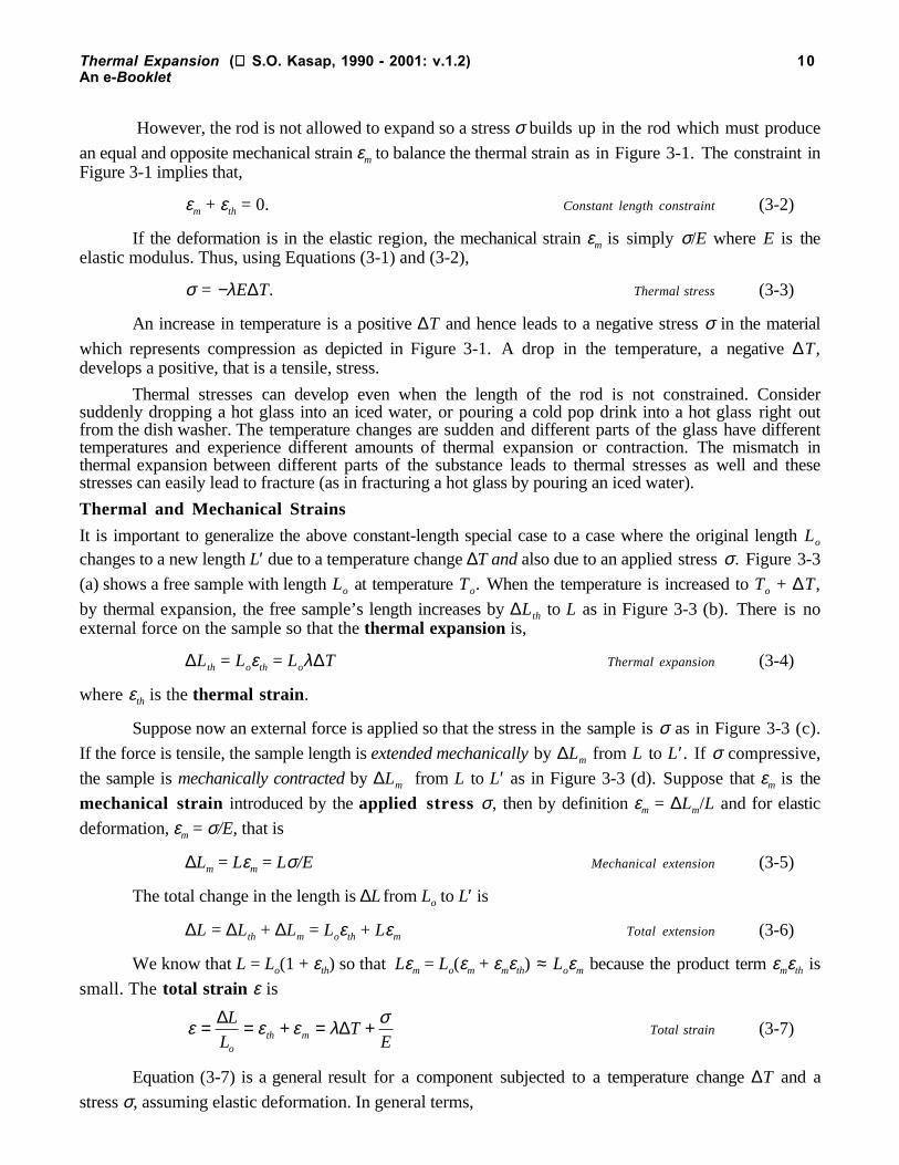
Molar heat capacity Cm of a solid can be determined from Debye’s heat capacity expression which,in graphical form, is shown in Figure 2-1. This graph represent the molar heat capacity of all solids as afunction of temperature, normalized with respect to the Debye temperature. For example, for silicon, TD =625 K, and at room temperature, T = 300 K, T/TD = 0.48 and Cm is about 0.81(3R). This point is on thetemperature sensitive portion of the Debye curve as shown in Figure 2-1 which means that Cm and hence λdepend on the temperature. Strictly, therefore, we cannot simply use a temperature independent linearexpansion coefficient for silicon at room temperature and calculate size changes by Equation (1-2). Thesituation is even worse for diamond where at room temperature Cm is on the steepest slope of the Cm vs. Tbehavior in Figure 2-1.
0
0.1
0.2
0.3
0.4
0.5
0.6
0.7
0.8
0.9
1
0
5
10
15
20
25
0 0.1 0.2 0.3 0.4 0.5 0.6 0.7 0.8 0.9 1
Cm = 3R
Cu
Diamond(TD = 1860 K)
Si (TD = 625 K)
Cm
J mol-1Cm/(3R)
T / TD
Debye molar heat capacity curve. The dependence of the molar heatcapacity Cm on temperature with respect to the Debye temperature: Cm vs.T/TD. For Si, TD = 625 K so that at room temperature (300 K), T/TD = 0.48and Cm is only 0.81(3R).
Figure 2-1
2.1. Example: Grüneisen's law for diamondGiven that diamond has a bulk modulus of 443 GPa, Debye temperature of 1860 K, its density is 3.51 gcm-3 and its atomic mass is 12 g mole-1, estimate its linear expansion coefficient at room temperature takingthe Grüneisen parameter as ~0.1.
Solution
From Figure 2-1, at room temperature, T = 300 K, T/TD = (300 K)/(1860 K) = 0.16 and Cm is only0.24(3R) = 6 J K-1 mol-1. Applying the Grüneisen formula,

Thermal Expansion ( S.O. Kasap, 1990 - 2001: v.1.2) 9An e-Booklet
λ γ ρ= ≈ × ×× ×
− − −
− −3 3 0 13 51 10 024 25
12 10 443 10
3 3 1 1
3 1 9
C
M Km
at
( . )( . )( . )
( )( )kg m J K mol
kg mol Pa
or λ ≈1.2 × 10⁻⁶ K-1
which is about the right order of magnitude as the experimental value (~1 × 10⁻⁶ K-1).
3. Thermal Stresses
Thermal Stress
Consider a metal rod that has its ends rigidly held (perhaps welded) between two fixed walls as depictedFigure 3-1 so that the length of the rod is always Lo. Suppose that the rod has a length Lo at To. Thismeans that at To, the rod experiences no stresses. If the temperature increases from To to T, the rod tries toexpand but it is constrained by the two walls, and therefore experiences a compressive stress exerted bythe two walls. If the temperature decreases, the rod tries to contract but it is prevented to do so by thewalls, and thus experiences tensile stresses. These stresses are induced by temperature changes and arecalled thermal stresses. If the thermal stresses are sufficiently large, they may exceed the yield strength ofthe rod material and lead to plastic deformation and even fracture. Suppose that the rod is made of a brittlematerial and the temperature drops so much that the tensile stress in the rod exceed the critical stress forcrack propagation (the Griffith critical stress), then the rod will fracture as depicted in Figure 3-2.
A constrained specimen experiences thermal stresswhen the temperature changes. The rise in temperatureleads to a compressive stress in the sample.
Lo
To T T
Figure 3-1
Lo
To T T
Crack
Tensile thermal stress, due to a temperature drop, exceeds the criticalstress for crack propogation and thereby causes the fracture of a brittlematerial.
Figure 3-2
If the rod in Figure 3-1 were free to expand when the temperature changes by an amount ∆T, thenthe strain due to this temperature change, thermal strain, would be
εth = ∆L/Lo = λ∆T. Thermal strain (3-1)
Thermal Expansion ( S.O. Kasap, 1990 - 2001: v.1.2) 10An e-Booklet
However, the rod is not allowed to expand so a stress σ builds up in the rod which must produce
an equal and opposite mechanical strain εm to balance the thermal strain as in Figure 3-1. The constraint inFigure 3-1 implies that,
εm + εth = 0. Constant length constraint (3-2)
If the deformation is in the elastic region, the mechanical strain εm is simply σ/E where E is theelastic modulus. Thus, using Equations (3-1) and (3-2),
σ = −λE∆T. Thermal stress (3-3)
An increase in temperature is a positive ∆T and hence leads to a negative stress σ in the material
which represents compression as depicted in Figure 3-1. A drop in the temperature, a negative ∆T,develops a positive, that is a tensile, stress.
Thermal stresses can develop even when the length of the rod is not constrained. Considersuddenly dropping a hot glass into an iced water, or pouring a cold pop drink into a hot glass right outfrom the dish washer. The temperature changes are sudden and different parts of the glass have differenttemperatures and experience different amounts of thermal expansion or contraction. The mismatch inthermal expansion between different parts of the substance leads to thermal stresses as well and thesestresses can easily lead to fracture (as in fracturing a hot glass by pouring an iced water).
Thermal and Mechanical Strains
It is important to generalize the above constant-length special case to a case where the original length Lo
changes to a new length L′ due to a temperature change ∆T and also due to an applied stress σ. Figure 3-3
(a) shows a free sample with length Lo at temperature To. When the temperature is increased to To + ∆T,
by thermal expansion, the free sample’s length increases by ∆Lth to L as in Figure 3-3 (b). There is noexternal force on the sample so that the thermal expansion is,
∆Lth = Loεth = Loλ∆T Thermal expansion (3-4)
where εth is the thermal strain .
Suppose now an external force is applied so that the stress in the sample is σ as in Figure 3-3 (c).
If the force is tensile, the sample length is extended mechanically by ∆Lm from L to L′. If σ compressive,
the sample is mechanically contracted by ∆Lm from L to L′ as in Figure 3-3 (d). Suppose that εm is the
mechanical strain introduced by the applied stress σ, then by definition εm = ∆Lm/L and for elastic
deformation, εm = σ/E, that is
∆Lm = Lεm = Lσ/E Mechanical extension (3-5)
The total change in the length is ∆L from Lo to L′ is
∆L = ∆Lth + ∆Lm = Loεth + Lεm Total extension (3-6)
We know that L = Lo(1 + εth) so that Lεm = Lo(εm + εmεth) ≈ Loεm because the product term εmεth is
small. The total strain ε is
ε ε ε λ σ= = + = +∆ ∆L
LT
Eoth m Total strain (3-7)
Equation (3-7) is a general result for a component subjected to a temperature change ∆T and a
stress σ, assuming elastic deformation. In general terms,

Thermal Expansion ( S.O. Kasap, 1990 - 2001: v.1.2) 11An e-Booklet
Total strain = Thermal strain + Mechanical strain
If the final length L′ is constrained, for example to Lo, as in Figure 3-1, then ∆L =0, ε = 0 and we
obtain the results above, σ = − Eλ∆T, a thermal stress in the component.
To To + T
Lo
To + T
Tension
Free
Applied stress
Free
(a) (b) (c)
(a) A sample of length Lo at To. (b). Thermal expansion without any external constriction
changes the length to L. (c) An applied external force changes the length further to L . In thisexample, the stress is tensile and the new length is longer; the sample is extended. (d) If theapplied force is compressive, the new length L will be shorter than L and the sample will becompressed.
Lo
LL
Lth
To + T
Compression
Applied stress
(d)
L
Lm
Lm
Figure 3-3
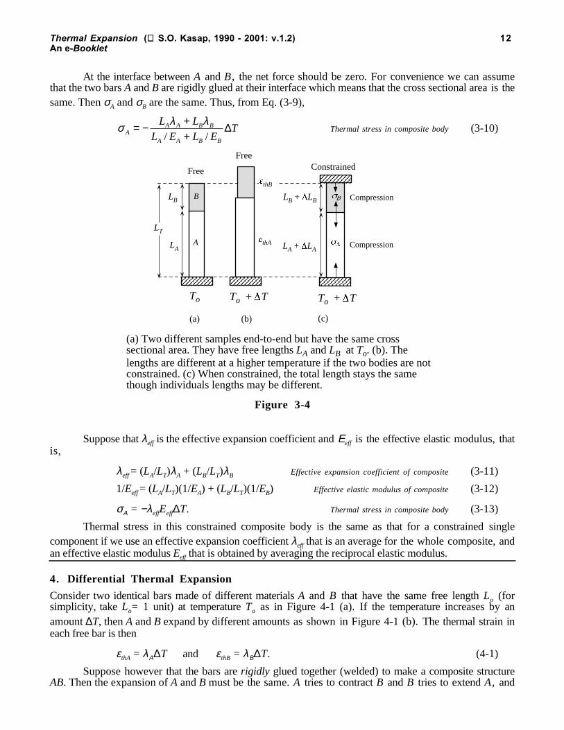
3.1. Example: A composite body with two constrained components in seriesConsider two bodies A and B made of different materials A and B that have different thermal expansioncoefficient λA and λB respectively standing end-to-end as in Figure 3-4 (a). Suppose that the lengths are LA
and LB at a temperature of To as shown in Figure 3-4 (a). If the temperature is raised by ∆T and the bodiesare not constrained as in Figure 3-4 (b), then the thermal strain in each will be
εthA = λA∆T and εthB = λB∆T
However, if the two bars are constrained along their length as in Figure 3-4 (c) so that the totallength is still LT then each bar will have a stress preventing expansion and this stress in each bar iscompressive. Thermal strains and mechanical strains in each bar should be such that the changes in thelength LA and LB must cancel to keep ∆LT = 0.
LT = LA + LB
then ∆LT = ∆LA + ∆LB = 0 Length constraint (3-8)
The change ∆LA is due to thermal strain and mechanical strain, and the mechanical strain is σA/EA where σA
is the stress in A and EA is the elastic modulus of A. If σB is the stress in B and EB is the elastic modulus ofB, then
LAλA∆T + LAσA/EA + LBλB∆T + LBσB/EB = 0. (3-9)
Thermal Expansion ( S.O. Kasap, 1990 - 2001: v.1.2) 12An e-Booklet
At the interface between A and B, the net force should be zero. For convenience we can assumethat the two bars A and B are rigidly glued at their interface which means that the cross sectional area is thesame. Then σA and σB are the same. Thus, from Eq. (3-9),
σ λ λA
A A B B
A A B B
L L
L E L ET= − +
+/ /∆ Thermal stress in composite body (3-10)
A
B
To To + T
LA
LB
To + T
thB
thA
Compression
Compression
LT
FreeConstrainedFree
(a) (b) (c)
LB + LB
LA + LA
(a) Two different samples end-to-end but have the same crosssectional area. They have free lengths LA and LB at To. (b). Thelengths are different at a higher temperature if the two bodies are notconstrained. (c) When constrained, the total length stays the samethough individuals lengths may be different.
Figure 3-4
Suppose that λeff is the effective expansion coefficient and Εeff is the effective elastic modulus, thatis,
λeff = (LA/LT)λA + (LB/LT)λB Effective expansion coefficient of composite (3-11)
1/Eeff = (LA/LT)(1/EA) + (LB/LT)(1/EB) Effective elastic modulus of composite (3-12)
σΑ = −λeffEeff∆T. Thermal stress in composite body (3-13)
Thermal stress in this constrained composite body is the same as that for a constrained singlecomponent if we use an effective expansion coefficient λeff that is an average for the whole composite, andan effective elastic modulus Eeff that is obtained by averaging the reciprocal elastic modulus.
4. Differential Thermal Expansion
Consider two identical bars made of different materials A and B that have the same free length Lo (forsimplicity, take Lo= 1 unit) at temperature To as in Figure 4-1 (a). If the temperature increases by anamount ∆T, then A and B expand by different amounts as shown in Figure 4-1 (b). The thermal strain ineach free bar is then
εthA = λΑ∆T and εthB = λΒ∆T. (4-1)
Suppose however that the bars are rigidly glued together (welded) to make a composite structureAB. Then the expansion of A and B must be the same. A tries to contract B and B tries to extend A, and

Thermal Expansion ( S.O. Kasap, 1990 - 2001: v.1.2) 13An e-Booklet
the result is a composite expansion εAB that is greater than that of A but less than that of B as indicated in
Figure 4-1 (c). Consequently there are induced thermal stresses in both bars. The stress σΑ in A tries to
extend A and causes a mechanical strain εmA. The stress σΒ in B tries to contract B and causes a mechanical
strain εmB which is in the opposite direction to εmA. The net force on the composite bar AB must be zero;otherwise the bar will fly away under the net force. Since A and B have the same cross sectional area, thetwo stresses therefore have the same magnitude but are in opposite directions. That is, the stress σΑ in A is
tensile (positive) so that σA = +σ, and the stress σΒ in B is compressive (negative) so that σB = −σ. If εmAB
is the final strain in the composite AB then, assuming elastic deformation,
εAB = λΑ∆T + εmA = λΒ∆T + εmB (4-2)
or εAB = λΑ∆T + σ/EA = λΒ∆T − σ/EB (4-3)
where EA and EB are the elastic moduli of A and B respectively. We can therefore calculate the stressesgiven the temperature change, linear expansion coefficients and elastic moduli. Solving the two we find
σ = [1/EA + 1/EB]-1(λB − λA)∆T. (4-4)
Lo=1 A B
AB
L A
L B
To To + T
A BLA LB
To + T
(a) (b) (c)
thBthA AB
CompressionTension
A B
(d)
To + T
(a) Two different samples of idential length at To. (b) The lengths are different at ahigher temperature if the two are separate. (c) The expansions (strains) are thesame if the two have been glued together. (d) A bimetallic strip has two thin platesfrom different metals rigidly connected. The stresses are reduced by the bending ofthe strip (exaggerated)
Figure 4-1
The induced thermal stresses in A and B clearly depend on the differential thermal expansioncoefficient (λB − λA). Even if the deformation is not elastic, the amount of thermal stress will still dependon the differential thermal expansion coefficient. Equation (4-4) applies to the special case where the barshave the same geometry (same length Lo at To and same cross sectional area). The case where the two barshave different cross sectional areas leads to different stresses in the individual bars as discussed inExample 4.1.
If the metal bars are thin plates then the induced thermal stresses lead to the bending of thebimetallic strip as depicted in Figure 4-1 (d). The reason is that the induced thermal stresses can be reducedif the composite bends in such a way that the strain along the length of B is more than that along the lengthof A. Consider for example two welded thin metal strips A and B of equal length Lo at To as in Figure 4-2(a). When the temperature increases by ∆T, B extends more than A so that the extension in lengths can

Thermal Expansion ( S.O. Kasap, 1990 - 2001: v.1.2) 14An e-Booklet
only be accommodated if the two metal system bends to form an arc of a circle centered at O as in Figure4-2 (b). Center-to-center separation of the strips is δR. Suppose that LA and LB are the new lengths, LA <LB. Then
LA = Lo(1 + λA∆T) and LB = Lo(1 + λB∆T)
Since both lengths have the same angle θ at O in Figure 4-2 (b),
Rθ = LA = Lo(1 + λA∆T)
and (R + δR)θ = LB = Lo(1 + λB∆T)
so that subtracting one from the other, we get,
θδR = Lo(λB − λA)∆T
Thus the angle θ is proportional to the temperature change ∆T and to the differential thermal
expansion coefficient (λB − λA). The deflection h can be calculated from the geometry and it is given by h =
R(1 − cosθ).
(a) Two different thin metals of idential length at To. (b) The lengths are differentat a higher temperature. B expands more than A. The two metals bend to form anarc of a circle of centered at O with a radius R. The acr subtends an angle at O.
O
R
R
hh
R h
Lo A
B
A
B
To To + T
Figure 4-2
4.1. Example: A composite body subject to a temperature changeConsider a rectangular body A glued to a rectangular body B as shown in Figure 4-3, identical length andwidth but the thicknesses are different. Perhaps a practical example would be the application of glaze to aceramic object, where A is the glaze and B is the ceramic object. Another example would be a thinsemiconductor film (A) deposited on a substrate (B), such as an a-Si:H (hydrogenated) thin film on a glasssubstrate. Steels are often are hardened by the surface diffusion of carbon so that A would be the carbon-rich surface region and B would be the interior of the steel.
Assuming elastic deformation, determine the stresses in each slab when the temperature change is∆T with respect to the stress free state. Obtain the stress in the layer A when this layer is much thinner thanB.
Solution

Thermal Expansion ( S.O. Kasap, 1990 - 2001: v.1.2) 15An e-Booklet
Suppose that the stresses in A and B are σA and σB which would be in opposite directions, one negativeand the other positive, as shown in Figure 4-3. Obviously the directions of these stresses would dependon the differential expansion coefficient and should come out naturally in the analysis. Suppose that thelinear expansion coefficient λA of A is greater than λB that of B. When the temperature increases, A tries toexpand more than B but it is prevented by B. The stress in A is therefore compressive (negative) as shownin Figure 4-3. On the other hand, the stress in B is tensile (positive) inasmuch as A tries to stretch B. In afirst order analysis, we can assume that the stresses are reasonably uniform across each slab.
There should be no net force at the interface between A and B otherwise the composite body willnot be in equilibrium (it will fly away obeying force = mass × acceleration). Thus,
Force in A + Force in B = 0
that is, σA(tAw) + σB(tBw) = 0
so that σB = −σA(tA/tB) Thermal stresses are in opposite directions (4-5)
tB B
Lo AB
To + T
tA
w
Lo
Two different samples of idential length, identical width but differentthickness, glued together face to face over length width.
A
Figure 4-3
The stress free state corresponds to both slabs having the length Lo at To. If they were free, thethermal strain after a temperature rise of ∆T in each would be,
εthA = λΑ∆T and εthB = λΒ∆T. (4-6)
At To + ∆T, the total strain in each is the same due to the constraint. Each expand by the same
amount LoεAB. Thus,
εAB = λΑ∆T + εmA = λΒ∆T + εmB
or εAB = λΑ∆T+ σΑ/EA = λΒ∆T + σΒ/EB (4-7)
Equation (4-7) contains both σA and σB but the two are related by Equation (4-5). Thus we canobtain the individual stresses,
σ λ λAB A B
A A B BA B
t E E
t E t ET= −
+−( )∆ (4-8)
and σ λ λBA A B
A A B BA B
t E E
t E t ET=
+−( )∆ (4-9)
Thermal Expansion ( S.O. Kasap, 1990 - 2001: v.1.2) 16An e-Booklet
The negative sign in Equation (4-8) does not necessarily indicate a compressive stress but rather σA
is in the opposite direction to σB. We can further simplify these equations by noting that if A is muchthinner than B (for example, A is a thin coating on a thick slab B) so that tB >> tA then we would expecttBEB >> tAEA so that Equation(4-8) becomes,
σΑ = −EA(λΑ − λΒ)∆T, Thermal stress in a thin film coating (4-10)
and, of course, σΒ = −(tA/tB)σA.
Clearly, the stress in the thin A layer is as if the layer was totally constrained. The stress in slab Bis very small as if the this slab were free. Furthermore, from Equation (4-7), we note that the strain in B isalmost all thermal strain. B expands as if it were free. The strain in A is that in B. However, the thin layerA is forced the extend or contract by as much as B.
4.2. Example: A thin semiconductor film on a substrate
Consider a thin film of a-Si:H (hydrogenated amorphous silicon) of 1 µm thickness that is deposited on a
glass substrate of thickness 5 mm at a temperature of about 240 °C. Following the deposition, the device
is allowed to cool to room temperature, 20 °C. Given that the thermal expansion coefficient of silicon and
glass are about 4 × 10⁻⁶ and 7 × 10⁻⁶ K-1 respectively, and the elastic modulus of silicon and glass are about100 GPa and 70 GPa respectively, calculate the strain and the stress in the thin semiconductor film. Whatis the strain and stress in the glass substrate?
Solution
We can directly apply Equation (4-10) as tB >> tA. Thus, the stress in the thin film is,
σΑ ≈ −EA(λΑ − λΒ)∆T = −(100 Gpa)(4 × 10⁻⁶ °C-1 − 7 × 10⁻⁶ °C-1)(20 °C − 240 °C)
σΑ = −66 MPa (negative means compressive).
The stress σB in the glass substrate is tensile but its magnitude is negligible a inasmuch as it is afactor of tB/tA = 5000 smaller. The strain in the thin film (and also in the composite) is thermal strain plusmechanical strain, as in Equation (4-7),
εAB = λΑ∆T − σΑ/EA = −λΒ∆T = −0.0013 (compression)
We should note that the magnitude of strain in A is the thermal strain εB = λΒ∆T in B. The thin filmcoating A is forced to contract as much as the natural thermal contraction of substrate B.
5. Thermal Fatigue and Thermal Failure of Soldered joints
In certain applications, a device may be subjected to thermal cycling, that is, its temperature is changedperiodically with time. Consequently, there will be induced strains and stresses in certain parts of thedevice that are also cycled with time in a similar fashion to the mechanical fatigue experiments where acomponent is subjected to a cyclic stress. We consider an example in electronics to illustrate thisphenomenon and how it may lead to mechanical failure as a result of thermal cycling, that is, thermalfatigue.
Flip chip mounting and bonding is used in some semiconductor industries for bonding silicon ICchips to ceramic substrates that support the chip and various other components. Figure 5-1 (a) shows atypical flip chip bonding in which a Si chip has been soldered, up side down, to a copper contact pad on asubstrate. Initially the chip has solder blobs (or balls) at its metal contact pads (called interconnects) whichhave been placed there during the fabrication process. The chip is then flipped and placed on to the ceramicsubstrate with the solder blobs resting on the copper contact pads on the substrate. The chip has to be linedup so that the solder blobs line up with the pads on the ceramic but this is not as difficult as it may seem.

Thermal Expansion ( S.O. Kasap, 1990 - 2001: v.1.2) 17An e-Booklet
When heated the solder blobs melt, wet the metal pads (and thereby become aligned) and form solderedjoints. An example of a soldered joint is shown in Figure 5-1 (b).
Si Chip
Substrate
Flipped chip
Solder Cu contact padMetal contact
on chip
Lo
Solder balls Circuits
Ceramic substrate
Si Chip
Chip
Metallicconnections
(a)
Si IC Chip
Substrate
Solder
Metal contactonchip
Cu contact padon thesubstrate
hsol
Lo
(b) (c)
Substrate
Si IC Chip
(a) A schematic illustration of flip chip bonding and a flip chip soldered IC chip on asubstrate. (b) A schematic illustration of the soldered joint. (c) The same joint under shearstresses due to an increase in the temperature.
Figure 5-1
When the device is operating it will dissipate heat which is conducted primarily through thesoldered joint. Eventually the device and the pad will reach a steady temperature which is ∆T above theroom temperature. Since the thermal expansion coefficients of the silicon chip and the substrate (typicallyalumina) are different, the two components expand by different amounts. The top and the bottom surfacesof the solder therefore experience forces that oppose each other which leads to a shear stress in the solderas depicted in Figure 5-1 (c).
Suppose that the thermal expansion coefficient for the chip is λ ch, and that for the substrate is λ sb.Suppose that Lo is the length of the solder from the center of the chip as shown in Figure 5-1 (b). We cantake this point to be the neutral point where the chip and the substrate do not expand relative to each other.Then the relative expansion ∆L between the chip and the substrate will be
∆L = Lo (λsb − λch) ∆T
We will assume that all the strain is taken up by the solder rather than the metal pads which arethinner. The solder then experiences the maximum possible shear strain, as depicted in Figure 5-1 (c). Themaximum shear strain γ is the relative tangential displacement of the solder faces, ∆L, per unit height, or

Thermal Expansion ( S.O. Kasap, 1990 - 2001: v.1.2) 18An e-Booklet
γ = ∆L/hsol = [Lo(λsb − λch)∆T] / hsol
The induced thermal strain is directly proportional to the differential thermal expansion coefficientλsb − λch. If this strain were totally in the elastic deformation range, then we can determine the shear stress
τ by
τ = G[Lo (λsb − λch) ∆T] / hsol
Suppose that we consider a “large” chip which has a half-length Lo ≈ 1 mm, and that the solder
height hsol ≈ 50 µm. We can now calculate the “typical” strains and stresses experienced when the chip is
turned on and the temperature rises by say 40 °C (from 25 to 65 °C). From materials data tables, for Si,
λch ≈ 2.5 ×�10−6 K-1, for an alumina substrate, λsb ≈ 6 × 10⁻⁶ K-1.
Thus the maximum shear strain is
γ = ∆L/hsol = [Lo(λsb − λch)∆T] / hsol
or, γ = (1 × 10⁻³ m)(6 × 10⁻⁶ K-1 − 2.5 × 10⁻⁶ K-1)(40 K) / (50 × 10-6 m)
that is, γ = 0.0028 or 0.28 %
This amount of shear strain is in the plastic deformation region and we cannot use τ = γ G tocalculate the shear stress which applies only in the elastic region.
If the Si chip is turned on and off so that the temperature rises and falls by an amount ∆T, then thesolder will experience a cyclic shear strain and hence a cyclic shear stress. There is a likelihood of failureafter many cycles, say N. This type of failure is called fatigue. N can be anything from a few tens toperhaps 108 cycles depending on the magnitude of the shear strain or shear stress (and hence thetemperature swings experienced by the chip).
Figure 5-2 shows the fatigue behavior of a typical Sn-Pb solder. Instead of the usual stress vs.number of cycles , S-N, curve, we have a plot of shear strain vs. number of cycles to failure, that is a γ-N
curve. A γ-N curve (line) at a given temperature and cycling frequency represents how the number of
cycles to failure N depends on the shear strain γ in the solder under those conditions. While theexperiments in Figure 5-2 have been done at a constant temperature, we can nonetheless use the results toestimate the failure times under thermal fatiguing. The shear strain of 0.3% in the above examplecorresponds to N ≈ 4 × 10⁴ on the E-curve, or a time of some 100 years or so to fail when cycled once a
day at 65 °C. However, if cycled 4 times per hour at 100 °C, the intersection on the D-line shows that itwill fail after about 1.9 years. It should be emphasized that such curves only provide order of magnitudeestimates as failure by fatigue has a degree of statistics associated with it and further these curves havebeen obtained at one temperature under a given cycling condition. Nonetheless, they are useful inidentifying safe operating margins. In addition, the values of Lo and hsol were taken to represent a largestrain to highlight thermal fatigue.
It is should be remembered that the solder will also have a degree of residual shear strain thatbuilds up as the solder joint cools from the fusion temperature down to room temperature. This residualstrain was neglected in the above analysis.

Thermal Expansion ( S.O. Kasap, 1990 - 2001: v.1.2) 19An e-Booklet
100 102 104 106
Number of cycles to failure
Shear strain (%)100
10
0.1
A
BC
DE
1
101 103 105
A: 25 C and 300 cycles hr-1
B: 100 C and 300 cycles hr-1
C: 25 C and 4 cycles hr-1
D: 100 C and 4 cycles hr-1
E: 65 C and 1 cycles day-1
Fatigue behavior of Sn63Pb37 solder as shear strain vs. numberof cycles for different cycling frequencies and temperatures.
= 0.4%
Figure 5-2
ADDITIONAL TOPICS
6. Grüneisen’s Law
Relative displacement, x0
B C
U(x) = PE
x
U
O
An atom in the crystal would be vibrating between B and C on the PE curve. At Band C, its total energy is PE (or U) because the vibrational velocity is zero. At O,its total energy is kinetic energy because the PE is zero.
Figure 6-1

Thermal Expansion ( S.O. Kasap, 1990 - 2001: v.1.2) 20An e-Booklet
We can derive Grüneisen’s law as follows. Consider the potential energy curve in Figure 6-1. Supposethat we measure the potential energy U with respect to the minimum; we have arbitrarily taken the zeroenergy reference at Umin. If x is the relative displacement, that is x = r − ro, then we can express the PEcurve in Figure 6-1 as
U = a2x2 + a3x
3 (5-1)
The net force is then proportional to the derivative of this expression,
FdU
dxa x a x= − = − −2 32 3
2 (5-2)
The average force (average over time) must be zero in equilibrium,
F a x a x= = − −0 2 32 32 (5-3)
which gives a relationship between the average displacement and average square displacement. It shouldbe emphasized that the potential energy U is minimum when x = 0, but the average value of x does notcoincide with x = 0 because of the asymmetry of the curve. Thus,
xa
ax= −3
23
2
2 (5-4)
Although the atoms will not be executing an ideal simple harmonic motion (which requires theforce in Equation 5-2 to be simply proportional to −x), in an approximate analysis we can assume perfectsimple harmonic oscillations. In such oscillations, the average potential energy PE is the same as theaverage kinetic energy KE. When the vibrating atoms in Figure 6-1 is at B or C, its total energy is allpotential energy U. At B or C, the atom is about to reverse its direction of vibration and its velocity is zerowhich means the kinetic energy KE is also zero. On the other hand, when the atom is at point O, its PE iszero, but its KE is maximum. Thus the average potential energy U of the vibrating atom is 1/2U. Thesecond term a2x
2 in Equation (5-1) represents most of the potential energy. Thus, per atom,
U a x U≈ =22 1
2(5-5)
The total energy E of the atom is PE + KE which is U. Thus, with E = U in Equation (5-5),
xa
2
22= E
(5-6)
We can use Equation (5-6) in Equation (5-4) to obtain the fractional average displacement,
xa
a a= −
32 2
3
2 2
E(5-7)
By the definition of the linear expansion coefficient λ, we get,
λ γ= = ⋅ − ⋅ ⋅ =1 1 3
2 23
23
2 22
2r
d
dTx
r
a
a a
d
r aC
o o o
( )1 1
atom
EdT
(5-8)
where by definition γ = −(roa3)/(2a2) is the Grüneisen parameter and Catom is the heat capacity per atomsince dE/dT = Catom.
The next step involves faithfully accepting the relationship between the bulk modulus and thepotential energy curve U which is derived in Appendix I. The bulk modulus K is related to the U(x) curveby

Thermal Expansion ( S.O. Kasap, 1990 - 2001: v.1.2) 21An e-Booklet
Kr
d U
dr r
d U
dxo r r o xo
=
=
= =
19
19
2
2
2
20
(5-9)
Clearly, the second derivative in Equation (5-9) can be obtained by differentiating Equation (5-1)twice,
d U
dxa
x
2
20
22
==
(5-10)
which gives the bulk modulus as
K = (2a2)/(9ro) (5-11)
We can now substitute for a2 in terms of K in Equation (5-8), to get,
λ γ γ= = ⋅39
132 3r r K
CK
C
ro o o
1 1atom
atom
( )(5-12)
But, ro3 is roughly the volume associated with one atom which means that Catom/ro
3 is the heatcapacity per unit volume, Cv. Thus,
λ γ= 13
C
Kv Grüneisen’s law (5-13)
The reason for not substituting K for a2 again in γ = −(roa3)/(2a2) is that a3/a2 gauges the extent ofasymmetry with respect to symmetry and therefore is more useful than the absolute value of a3 alone.

Thermal Expansion ( S.O. Kasap, 1990 - 2001: v.1.2) 22An e-Booklet
APPENDIX I
7. Bulk Modulus and the Potential Energy Curve
Consider a crystal of volume Vo (this can even be a unit cell). When subjected to an external pressure P,the volume contracts from Vo to V and the change in the volume ∆V = V−Vo.
W PdV KV V
VdV K
V V
VK
V V
VV
Vo
oV
Vo
o V
Vo
oo o o
= =−
=−
=
−∫ ∫–( ) ( ) ( )1
2
1
2
2 2
Since ∆V = V−Vo,
W KV
Vo= 1
2
2∆(6-1)
Interatomic separation changes from ro to r = ro−∆r. We note the potential energy per atom in theunit cell is the U(r) vs. r in Equation (1-3). At r = ro, U is minimum (crystal in equilibrium) and dU/dr = 0.Expansion of U about ro is
U r U rdU
drr
d U
drro
r r r ro o
( ) ( ) ...= +
+
+= =
∆ ∆12
2
22
Since dU/dr = 0 and we can neglect ∆r3 and higher terms, the change in the potential energy is
∆ ∆Ud U
drr
r ro
=
=
12
2
22 (6-2)
We now need to relate ∆V to ∆r and Vo to ro. In the simplest case, we would consider a cubic unitcell with a side ao and an atom at the center. Then the interatomic separation ro is the same as the cube sideao. Then Vo = ao
3 = ro3 and V = (ro+∆r)3 so that
∆ ∆ ∆ ∆ ∆V r r r r r r r ro o o o= + − = + +( )3 3 2 2 33 3
i.e. ∆ ∆V r ro≈ 3 2 (6-3)
where we have neglected the small ∆r2 and ∆r3 terms with respect the other terms.
Using Equation (6-3) in (6-1), work done on the unit cell is
W KV
VK
r r
rK r r
o
o
oounit-cell = = =1
2
1
2
3 1
29
2 2 2
32∆ ∆
∆( )
( ) (6-4)
Equating the work done Wunit-cell in Equation (6-4) to the energy ∆U stored in compressing thebond in Equation (6-2) give
12
912
22
22Kr r
d U
drro
r ro
∆ ∆=
=
that is Kr
d U
dro r ro
=
=
19
2
2 Bulk modulus and PE curve (6-5)
Thermal Expansion ( S.O. Kasap, 1990 - 2001: v.1.2) 23An e-Booklet
NOTATION
a2 coefficient of the parabolic term in the seriesexpansion of the interatomic potential energyU(r)
a3 coefficient of the cubic term in the seriesexpansion of the interatomic potential U(r)
α V thermal coefficient of volume expansion (°C-1 orK-1)
Catom heat capacity per atom in the material (J K-1
atom-1)
Cm heat capacity per mole; molar heat capacity (J K-1
mol-1)
cs specific heat capacity (J K-1 kg-1)
Cv heat capacity per unit volume (J K-1 m-3)
δ a small change, an incremental change∆ change∆ volume strain (no units)∆U change in the potential energy, for example, ∆U
= U − Uminimum
∆T temperature change (°C or K)E elastic modulus (Pa or N m-2)E total energy (PE + KE) (J)ε strain (no units)εm mechanical strain; strain due to a stress (no
units)εth thermal strain; strain due to a temperature change
(no units)F force (N)
γ Grüneisen parameter that gauges the extent ofasymmetry in the potential energy of interatomicinteraction (no units)
G shear modulus (Pa or N m-2)γ shear strain (no units)h height (m)
k Boltzmann’s constant (k = R/NA = 1.3807 × 10⁻²³
J K-1)
K bulk modulus (Pa or N m-2)KE kinetic energy (J)
L length (m)
λ thermal coefficient of linear expansion (°C-1 or K-
1)
Lo original length at temperature To
Mat atomic mass (g mol-1)
N number of cycles to failureNA Avogadro’s number, number of atoms in 1 mole
of substance or in Mat grams of substance (NA =6.022 ×10²³ mol-1)
PE potential energy (J)
ρ density (g cm-3)
r interatomic separation (m)
rav average interatomic separation (m)
ro interatomic separation when the potential energyis minimum; equilibrium separation (m) (not tobe confused with the average separation which isdifferent)
σ stress (Pa or N m-2); positive for tensile andnegative for compressive.
τ shear stress (Pa or N m-2)
T temperature (K)
t thickness (m)
To original temperature; room temperature
U potential energy PE (J)
V volume (m3)
w width (m)W work; work done (J)
x displacement from equilibrium, x = r − ro
USEFUL DEFINITIONSBulk modulus K is volume stress (pressure) needed per unit elastic volume strain, and is defined by p = −K∆ where p is
the applied volume stress (pressure) and ∆ is the volume strain. It gauges the extent to which a body can bereversibly (and hence elastically) deformed in volume by an applied pressure in terms of the material properties.
Elastic modulus E is axial stress needed per unit elastic axial strain, and is defined by σ = Eε where σ is the applied stressand ε is the strain all along the same direction (axis). It gauges the extent to which a body can be reversibly (andhence elastically) deformed by an applied load in terms of the material properties.
Heat Capacity at constant volume is the increase in the energy of the system per degree increase in the temperature of thesystem, i.e. CV = (∂E / ∂T)V.
Heat is the amount of energy that is transferred from one system to another (or between the system and its surroundings) as aresult of a temperature difference. It is not a new form of energy but rather the transfer of energy from one body toanother by virtue of the random motions of their molecules. When a hot body is in contact with a cold body, heat istransferred from the hot to the cold body. What is actually transferred is the excess mean kinetic energy of themolecules in the hot body. Molecules in the hot body have higher kinetic energy and vibrate more violently and, as a

Thermal Expansion ( S.O. Kasap, 1990 - 2001: v.1.2) 24An e-Booklet
result of the collisions between the molecules, there is a net transfer of energy from the hot to the cold body untilthe molecules in both bodies have the same mean kinetic energy; when their temperatures are the same.
Kinetic molecular theory assumes that the atoms and molecules of all substances (gases, liquids and solids) aboveabsolute zero of temperature are in constant motion. Monatomic molecules (e.g. He, Ne) in a gas exhibit constantand random translational motion whereas the atoms in a solid exhibit constant vibrational motion.
Mechanical work is qualitatively defined as the energy expended in displacing a constant force through a distance. When aforce F is moved a distance dx, work done dW = F.dx. When we lift a body such as an apple of mass m (100 g) by adistance h (1 m), we do work by and amount F∆x = mgh (1 J) which is then stored as the gravitational potentialenergy of the body. We have transferred energy from ourselves to the potential energy of the body by exchangingenergy with it in the form of work. Further, in lifting the apple, the molecules have been displaced in orderlyfashion, all upwards. Work therefore involves an orderly displacement of atoms and molecules of a substance incomplete contrast to heat.
Mole of a substance is that amount of the substance which contains NA number of atoms (or molecules) where NA isAvogadro's number (6.022 × 10²³). One mole of a substance has a mass as much as its atomic (molecular) mass ingrams. For example 1 mole of copper contains 6.022 × 10²³ number of copper atoms and has a mass of 63.55grams.
Property is a characteristic or an attribute of a system which we can measure. Pressure, volume, temperature, mass, energy,magnetization, polarization, color are all properties of matter. Properties such as pressure, volume and temperaturecan only be attributed to a system of many particles (which we treat as a continuum). We note that heat and work arenot properties of a substance but represent energy transfers involved in producing changes in the properties.
PV Work is work done when a system (any substance) expands or contracts by in volume as a result of an external pressure,Pext acting on the system. For example, when the gas in a cylinder expands by dV against a piston it pushes thepiston against an external pressure of Pext and in doing so it does work by an amount PextdV. If the change in thevolume is done reversibly, i.e. the pressure of the system is only infinitesimally larger than the external pressure(expansion is therefore infinitely slowly), then P = Pext and dW = PdV. Maximum work is done by a system onlyduring a reversible change. Further, W = ∫PdV is a path function in that its value for a change from state A to state Bdepends on the path (processes).
Shear modulus G is shear stress needed per unit elastic shear strain, and is defined by τ = Gγ where τ is the applied shearstress and γ is the shear strain. It gauges the extent to which a body can be reversibly (and hence elastically)deformed by shearing forces in terms of the material properties.
Strain is a measure of the deformation a material exhibits under an applied stress. It is expressed in normalized units. Underan applied tensile stress, strain (ε) is the change in the length per unit original length, ∆L / Lo. When a shear stressis applied, the resulting deformation involves a shear angle. Shear strain is defined as the tangent of the shear anglethat is developed by the application of the shearing force. Volume strain ∆ is the change in the volume per unitoriginal volume; ∆ = ∆V/V.
Stress is force per unit area, F / A. When the applied force is perpendicular to the area it leads either to a tensile orcompressive stress, σ = F / A. If the applied force is tangential to the area then it leads to a shear stress, τ = F / A.
Thermal strain is the fractional change in the length of a body due to a change in the temperature when the body is notconstrained (not prevented from thermal expansion or contraction). If λ is the thermal expansion coefficient, Lo is theoriginal length of the body and ∆L is the change in the length, then the thermal strain εth = ∆L/Lo = λ∆T where ∆Tis the temperature change.
Thermal stress is the stress induced in a body as a result of the body being unable to thermally expand or contract due to atemperature change by virtue of being constrained. The change in the temperature does not lead to the normal freeexpansion or contraction and there is a mechanical strain induced in the body.
Unit cell is the most convenient small cell in the crystal structure that carries the properties of the crystal. The repetition ofthe unit cell in three dimensions, generates the whole crystal structure.
QUESTIONS AND PROBLEMS
1 . Iron (body centered cubic crystal structure) has a bulk modulus of 170 GPa, density of 7.9 g cm-3,heat capacity of 444 J K-1 kg-1 all at room temperature. Taking the Grüneisen parameter to be

Thermal Expansion ( S.O. Kasap, 1990 - 2001: v.1.2) 25An e-Booklet
roughly ~0.2, estimate the thermal coefficient of expansion for iron and compare it with theexperimental value of 12 × 10-6 K-1.
[Ans: 12.4 × 10⁻⁶ K-1]
2 . Zinc (hexagonal close-pack, HCP, crystal structure) has a bulk modulus of 69 GPa, density of7.14 g cm-3, heat capacity of 390 J K-1 kg-1 and a linear thermal expansion coefficient of 31 × 10-6
K-1, all at room temperature. Calculate the experimental Grüneisen parameter for Zn.
[Ans: 0.26]
3 . Silicon has the same crystal structure as germanium whose properties are listed in Table 1-1. Si hasa bulk modulus of 100 GPa, density of 2.3 g cm-3, atomic mass of 28.1 g mol-1, heat capacity permole that can be found from Figure 2-1 at any temperature given that its Debye temperature is 625K. Taking the Grüneisen parameter to be roughly the same as that for Ge, calculate the thermalexpansion coefficient of Si at room temperature and compare it with the experimental value of 2.6× 10⁻⁶ K-1.
[Ans: 4.5 × 10⁻⁶ K-1; clearly γ should be less]
4 . Suppose that the potential energy curve per atom with respect to the minimum Umin at r = ro can bewritten as
∆U = U − Umin = −A/rn + B/rm
where r is the interatomic separation, the A-term represents the long range attractive force and theB-term the short range repulsive force. Expand this equation about the equilibrium position ro as
∆U = a2(r−ro)2 + a3(r−ro)
2
and hence evaluate a2 and a3. Recall that at r = ro, dU/dr = 0. Show that
γ = 1/2 + (1/6)(m + n)
Typically n = 1 and m = 6 to 8 which makes γ close to unity. Thus, experimental γ valuesless than unity do not follow Grüneisen’s simple expression; a more elaborate theory that alsotakes into account the crystal structure is needed.
5. Engineers are laying steel rail tracks that are 20 m long during a winter day when the temperature is-10 °C. If the tracks are suppose to just touch each other when the temperature is 40 °C, a potentialmaximum temperature during the summer season, what should be the separation between thetracks? What is the thermal stress in the tracks if the engineers lay the tracks end-to-end in contact?Steel has a thermal expansion coefficient of 11 × 10-6 K-1 and an elastic modulus of 200 GPa.
[Ans: 1.1 cm; 110 MPa]
6. Show that the thermal expansion coefficient for an area is 2λ . Consider an aluminum square sheet
of area 1 cm2. If the thermal expansion coefficient of Al at room temperature (25 °C) is about 24 ×10-6 K-1, at what temperature is the percentage change in the area is +1%
[Ans: 233.3 °C]
7 . A device engineer fabricates a metal-semiconductor diode. The metal is a thin film of Al (notnecessarily pure Al) on a Si crystal wafer. Suppose that the Al film is 0.1 µm thick and the Si
crystal wafer is 100 µm thick. Estimate the temperature induced total strain in the Al film if the
device is taken from 25 °C down to the liquid nitrogen temperature 77 K (−196 °C). What is thestress if the deformation were elastic? The yield strength of this Al-alloy is 50 MPa. What is themechanical strain that results in yield (plastic deformation)? What is the mechanical strain in the Al

Thermal Expansion ( S.O. Kasap, 1990 - 2001: v.1.2) 26An e-Booklet
film? What is the stress in the Al film? Do you think the deformation of the Al thin film is elastic?Estimate the temperature at which the Al film begins to deform plastically (reaches the yield point)?
Over the temperature range of interest (from −196 to 25 °C), aluminum has a thermal
expansion coefficient of about 10 × 10-6 K-1 and silicon has a thermal expansion coefficient of
about 1 × 10⁻⁶ K-1. The elastic modulus of Al is 70 GPa.
[Ans: εmA = (Yield Strength)/EAl = 0.00071; σAl = 139 MPa; εtotal = εAB = 0.00022 or 0.022%; εmA =
0.002 = 0.2%; plastic deformation; about −54 °C]
8 . a Consider a composite body made up of two rods of length LA and LB glued together end-to-end at a temperature To, as Figure Q.8, and that the total length is constrained to be fixed. If thetemperature is changed by ∆T (+ or −) and the deformation is elastic, show that the lengths LB′ and
LA′ are,
LA′ = LA[1 + λA∆T + σA/EA ]
and LB′ = LB[1 + λB∆T + σB/EB ]
b Suppose that B is elastic throughout the deformation and A becomes plastic when σA = σyA
as illustrated in Figure Q.8 under a tensile stress. A fractures when the mechanical tensile strainreaches fracture strain, εfA. Show that when the temperature changes by ∆T, then mechanical strainin A is determined by,
εmALA + LAλA∆T + LBλB∆T + LB(σyA/EB) = 0
and that fracture occurs when ∆T = ∆Tf,
∆TL E L
L LfB yA B A fA
A A B B
= −+
+σ ε
λ λ/
Suppose that the composite body in Figure Q.8 represents a thin long brass rod (B) joinedthrough a solder (A) to a metal pad on an electronic board. Assume that the total length is fixed byvirtue of a spacer that has a negligible thermal expansion coefficient. Take LA = 0.1 mm, LB = 5cm, λA ≈ λB ≈ 15 × 10-6 K-1, EA ≈ 40 GPa, EB ≈ 100 GPa, εfA ≈ 0.2, σyA = 40 MPa. Estimate thetemperature change that will lead to the fracture of the solder joint. What is the required temperaturechange for fracture if the solder thickness is 1 mm? What are the assumptions and limitations of thetheory?
[Ans: ∆T = −53.2 °C; −288 °C. Fixed length constraint is somewhat artificial. See Q. 10]
[There are also stresses that are tangential to the A-B interface because the two components are “glued” and thesestresses may lead to cracking around the circumference and eventual failure if the temperature change is sufficientlylarge]

Thermal Expansion ( S.O. Kasap, 1990 - 2001: v.1.2) 27An e-Booklet
LB
Mechanical strain in A
yA
yA fAmA
Tensile stress in A
Plastic
Elastic
Fracture
LA
The composite body has two rods A and B glued together and it is constrained; totallength is always the same. Due to a temperature drop, both bodies experience tensilethermal stresses. Body A has a yield strength of yA and fracture strain of fA.
Figure Q.8
9 . A flip chip silicon IC (integrated circuit) is soldered onto metal interconnection tracks on analumina substrate. The chip half length is 500 µm, solder height is 50 µm. For the chip, λ ch ≈ 2.5
×�10−6 K-1, for the alumina substrate, λ sb = 6 �×10-6 K-1; for solder G = 14 GPa. Calculate the
residual shear stress and strain in the solder joint as the flip chip soldered circuit cools from 183 °Cdown to room temperature 20 °C.
10. Two rigid platforms are separated by brass spacers as in Figure Q.10. A glass rod connects apiezoelectric transducer (ultrasonic transducer) on the top platform to another piezoelectrictransducer on the lower platform to transmit ultrasonic waves between the two. Assume that theglass rod is glued at its ends to two platforms. Calculate the stress in the glass rod if thetemperature drops from 25 °C down to −50 °C. The separation Lo between the platforms is 10 cm
at 25 °C. Each brass spacer has a diameter of 4 mm. The glass rod has a diameter of 2 mm.
Thermal expansion coefficient of brass is 20 × 10-6 K-1, for glass it is 1 × 10⁻⁶ K-1. The elasticmoduli E of brass and glass are 100 GPa and 70 GPa respectively. What is the force acting(including its sign, tensile or compressive) on the adhesive between the glass rod and thetransducer (this force may break the adhesive). What is the force, if the temperature change is from25 °C to 90 °C

Thermal Expansion ( S.O. Kasap, 1990 - 2001: v.1.2) 28An e-Booklet
Glass rod Brass spacerBrass spacer
Rigid platform
Rigid platform
Two rigid platforms are separated by brass spacers. A glass rod connects apiezoelectric transducer (ultrasonic transducer) on the top platform to anotherpiezoelectric transducer on the lower platform to transmit ultrasonic wavesbetween the two.
Figure Q.10
1 1 . The resistance of a metal wire of diameter D, length L and resistivity ρ is given by,
RL
D= ρ
π4
2
Consider a change δR in R due to a change δT in the temperature. We can differentiate R with
respect to T by considering that ρ, L, D depend on T. Show that the fractional change in theresistance per unit temperature change is given by,
1R
dR
dT
= −α λ
where the temperature coefficient of resistivity, TCR (α), and the linear expansion coefficient λ aredefined by
αρ
ρ=
1 d
dTand λ =
=
1 1L
dL
dT D
dD
dT
What is your conclusion?
1 2 . a Consider three rectangular bodies A, B and C, of identical length Lo at To, and identicalwidth glued together face to face over their length × width faces as in Figure Q12. Suppose that A,B and C have elastic moduli that are about the same order of magnitude (not different by more thana factor 10) and the thicknesses follow the following relationship
tA << tB << tC,
that is C is very thick, B is thin and A is very thin. If the temperature changes from To to To + ∆T,show that, the total strain is
εABC ≈ λA∆T
and the induced stresses in each layer are
σB ≈ 0; σB ≈ EB(λA − λB)∆T; σC ≈ EC(λA − λC)∆T

Thermal Expansion ( S.O. Kasap, 1990 - 2001: v.1.2) 29An e-Booklet
Three different samples of idential length, identical width but differentthickness, glued together face to face over length width. Each has adifferent thickness.
A
B
CC
tA
tB
To + T
tC
Lo Lo
Figure Q.12
b A device engineer fabricates a sensor by depositing an a-Si:H film on a glass substrate andthen depositing an Al electrode onto the a-Si:H film. The device has the structure glass/a-Si:H/metal. The glass substrate is 10 mm thick. The a-Si: is 5 µm thick and the Al electrode is 0.2
µm thick. The expansion coefficients of glass, a-Si:H and Al are about 7 × 10⁻⁶ K-1, 4 × 10⁻⁶ K-1,
23 × 10-6 K-1 respectively. Elastic moduli are Eglass = 70 GPa, Ea-Si:H = 100 GPa, EAl = 70 GPa.Calculate the stress in each layer if the temperature drops from 25 °C to −50 °C.
[Ans: σglass = negligible; σa-Si:H = −22 MPa, compressive; σAl = 84 MPa, tensile; εtotal = −0.00052]

Thermal Expansion ( S.O. Kasap, 1990 - 2001: v.1.2) 30An e-Booklet
ACKNOWLEDGMENTSIt is a pleasure to thank Professor W. Szyszkowski for fruitful and exciting discussions on the subjectmatter. A quick search of Professor W. Szyszkowski in the literature citation index will generate numerousjournal references on the subject of thermal stresses in composite bodies.
Space shuttle Columbia gets fresh protective skin on its belly atKennedy Space Center following its 13th mission. Dark colored tilesmade of glass ceramic replace other damaged by debris; especiallyice sloughed off the main fuel tank during launch. Composed of 7%solid and 93% air, the tiles are superb insulators [Source: NationalGeographic, Vol. 184, No. 6, p. 46, December 1993].
“I often say that when you can measure what you are speakingabout, and express it in numbers, you know something about it; butwhen you cannot measure it, when you cannot express it in numbers,your knowledge is of a meagre and unsatisfactory kind.”
Lord Kelvin (William Thomson)From Lecture to the Institution of Civil Engineers, 3 May 1883
All material in this publication is copyrighted.
All rights reserved. No part of this publication may be reproduced, stored in a retrieval system, ortransmitted, in any form or by any means, electronic, mechanical, photocopying, recording, or otherwise,
without the prior written permission of the author.Permission is granted to individuals for downloading this document from the author’s website or his
CD-ROM for self-study only. Permission is hereby granted to instructors to use this publication as a class-handout if the author’s McGraw-Hill textbook Principles of Electronic Materials and Devices, SecondEdition, has been adopted as a requisite course textbook. The permission is valid only while the book
remains in adoption.
SPECIAL CUSTOM PUBLISHED e-BOOKLET S.O. Kasap, 1990-2001The author reserves all rights
Last Updated: 27 November 2002 (v.1.2)
First published in Web-Materials(Established 1996)
http://Materials.Usask.Ca