
THERMAL EFFICIENCY APPARATUS - Instituto …fisica.uc.cl/images/TD-8564_Eficiencia_Temica.pdf ·...
34
Instruction Manual and Experiment Guide for the PASCO scientific Model TD-8564 012-05443A 3/94 © 1991 PASCO scientific $10.00 THERMAL EFFICIENCY APPARATUS PASCO scientific Model TD-8564 THERMAL EFFICIENCY APPARATUS Model TD-8564 THERMAL EFFICIENCY APPARATUS THERMISTOR SELECT THERMISTOR SELECT PELTIER DEVICE PELTIER DEVICE WATER PUMP 7.5 - 12 VDC @500mA WATER PUMP 7.5 - 12 VDC @500mA COOLING WATER COOLING WATER HEATER 5Ω±1% 12 VDC MAX 5Ω±1% 12 VDC MAX 2.0Ω 2.0Ω 1.0Ω 1.0Ω 0.5Ω 0.5Ω THERMISTOR TABLE THERMISTOR TABLE KΩ 461 436 413 391 370 351 332 315 KΩ 461 436 413 391 370 351 332 315 °C -5 -4 -3 -2 -1 0 1 2 °C -5 -4 -3 -2 -1 0 1 2 KΩ 269 255 242 230 218 207 197 187 KΩ 269 255 242 230 218 207 197 187 °C 5 6 7 8 9 10 11 12 °C 5 6 7 8 9 10 11 12 KΩ 161 153 146 139 133 126 120 115 KΩ 161 153 146 139 133 126 120 115 °C 15 16 17 18 19 20 21 22 °C 15 16 17 18 19 20 21 22 KΩ 100 95.4 91.1 87.0 83.1 79.4 75.9 72 5 KΩ 100 95.4 91.1 87.0 83.1 79.4 75.9 72 5 °C 25 26 27 28 29 30 31 32 °C 25 26 27 28 29 30 31 32 KΩ 63.4 60.7 58.1 55.6 53.2 51.0 48.9 46 8 KΩ 63.4 60.7 58.1 55.6 53.2 51.0 48.9 46 8 °C 35 36 37 38 39 40 41 42 °C 35 36 37 38 39 40 41 42 KΩ 41.2 39.6 37.9 36.4 34.9 33.5 32.2 30 9 KΩ 41.2 39.6 37.9 36.4 34.9 33.5 32.2 30 9 °C 45 46 47 48 49 50 51 52 °C 45 46 47 48 49 50 51 52 KΩ 27.4 26.4 25.3 24.4 23.4 22.5 21.7 20 9 KΩ 27.4 26.4 25.3 24.4 23.4 22.5 21.7 20 9 °C 55 56 57 58 59 60 61 62 °C 55 56 57 58 59 60 61 62 KΩ 18.6 17.9 17.3 16.6 16.0 15.5 14.9 14 4 KΩ 18.6 17.9 17.3 16.6 16.0 15.5 14.9 14 4 °C 65 66 67 68 69 70 71 72 °C 65 66 67 68 69 70 71 72 KΩ 12.9 12.4 12.0 11.6 11.2 10.8 10.4 10 1 KΩ 12.9 12.4 12.0 11.6 11.2 10.8 10.4 10 1 °C 75 76 77 78 79 80 81 82 °C 75 76 77 78 79 80 81 82 KΩ 9.12 8.81 8.52 8.24 7.96 7.70 7.45 7 21 KΩ 9.12 8.81 8.52 8.24 7.96 7.70 7.45 7 21 °C 85 86 87 88 89 90 91 92 °C 85 86 87 88 89 90 91 92 KΩ 6.53 6.33 6.12 5.93 5.74 5.56 5.39 5 22 KΩ 6.53 6.33 6.12 5.93 5.74 5.56 5.39 5 22 °C 95 96 97 98 99 100 101 102 °C 95 96 97 98 99 100 101 102 Q c Q h T h T c Cold Reservoir Hot Reservoir Heat Engine W Includes Teacher's Notes and Typical Experiment Results
Transcript of THERMAL EFFICIENCY APPARATUS - Instituto …fisica.uc.cl/images/TD-8564_Eficiencia_Temica.pdf ·...

Instruction Manual andExperiment Guide forthe PASCO scientificModel TD-8564
012-05443A3/94
© 1991 PASCO scientific $10.00
THERMAL EFFICIENCYAPPARATUS
PASCO scientific
Model TD-8564THERMAL EFFICIENCYAPPARATUS
Model TD-8564THERMAL EFFICIENCYAPPARATUS
THERMISTORSELECT
THERMISTORSELECT
PELTIERDEVICEPELTIERDEVICE
WATERPUMP
7.5 - 12 VDC@500mA
WATERPUMP
7.5 - 12 VDC@500mA
COOLINGWATER
COOLINGWATER HEATER 5Ω±1%
12 VDC MAX5Ω±1%
12 VDC MAX
2.0Ω2.0Ω1.0Ω1.0Ω0.5Ω0.5Ω
THERMISTOR TABLETHERMISTOR TABLEKΩ
461436413391370351332315
KΩ
461436413391370351332315
°C
-5-4-3-2-1012
°C
-5-4-3-2-1012
KΩ
269255242230218207197187
KΩ
269255242230218207197187
°C
56789
101112
°C
56789
101112
KΩ
161153146139133126120115
KΩ
161153146139133126120115
°C
1516171819202122
°C
1516171819202122
KΩ
10095.491.187.083.179.475.972 5
KΩ
10095.491.187.083.179.475.972 5
°C
2526272829303132
°C
2526272829303132
KΩ
63.460.758.155.653.251.048.946 8
KΩ
63.460.758.155.653.251.048.946 8
°C
3536373839404142
°C
3536373839404142
KΩ
41.239.637.936.434.933.532.230 9
KΩ
41.239.637.936.434.933.532.230 9
°C
4546474849505152
°C
4546474849505152
KΩ
27.426.425.324.423.422.521.720 9
KΩ
27.426.425.324.423.422.521.720 9
°C
5556575859606162
°C
5556575859606162
KΩ
18.617.917.316.616.015.514.914 4
KΩ
18.617.917.316.616.015.514.914 4
°C
6566676869707172
°C
6566676869707172
KΩ
12.912.412.011.611.210.810.410 1
KΩ
12.912.412.011.611.210.810.410 1
°C
7576777879808182
°C
7576777879808182
KΩ
9.128.818.528.247.967.707.457 21
KΩ
9.128.818.528.247.967.707.457 21
°C
8586878889909192
°C
8586878889909192
KΩ
6.536.336.125.935.745.565.395 22
KΩ
6.536.336.125.935.745.565.395 22
°C
9596979899
100101102
°C
9596979899
100101102
Qc Qh
ThTc
ColdReservoir
HotReservoir
HeatEngineW
IncludesTeacher's Notes
andTypical
Experiment Results


012-05443A Thermal Efficiency Apparatus
i
Table of Contents
Copyright, Warranty and Equipment Return................................................... ii
Introduction ..................................................................................................... 1
Quick Start ....................................................................................................... 2
Theory ............................................................................................................. 3
HEAT ENGINE:
Introduction ............................................................................................... 3
Actual Efficiency ....................................................................................... 3
Carnot Efficiency....................................................................................... 3
Adjusted Efficiency ................................................................................... 3
HEAT PUMP (REFRIGERATOR):
Introduction ............................................................................................... 4
Actual Coefficient of Performance ............................................................ 4
Maximum Coefficient of Performance ...................................................... 4
Adjusted Coefficient of Performance ........................................................ 4
MEASUREMENTS USING THE THERMAL EFFICIENCY APPARATUS:
Direct Measurements ................................................................................. 5
Temperatures ....................................................................................... 5
Power Delivered to the Hot Reservoir (PH) ......................................... 6
Power Dissipated by the Load Resistor (PW) ....................................... 6
Indirect Measurements .............................................................................. 6
Internal Resistance............................................................................... 6
Heat Conduction and Radiation........................................................... 6
Heat Pumped from the Cold Reservoir................................................ 7
EXPERIMENTS:
1 — Heat Engine and Temperature Difference ......................................... 9
2 — Heat Engine Efficiency (Detailed Study) ......................................... 13
3 — Heat Pump Coefficient of Performance............................................ 17
4 — Thermal Conductivity ....................................................................... 20
5 — Load for Optimum Performance....................................................... 21
Teacher’s Guide.............................................................................................. 25
Technical Support ................................................................. Inside Back Cover

Thermal Efficiency Apparatus 012-05443A
ii
Credits
This manual authored by: Ann Hanks
This manual edited by: Ann Hanks and Eric Ayars
Teacher’s Guide written by: Eric Ayars
Copyright Notice
The PASCO scientific Model TD-8564 Thermal Effi-ciency Apparatus manual is copyrighted and all rightsreserved. However, permission is granted to non-profiteducational institutions for reproduction of any part ofthis manual providing the reproductions are used only fortheir laboratories and are not sold for profit. Reproduc-tion under any other circumstances, without the writtenconsent of PASCO scientific, is prohibited.
Limited Warranty
PASCO scientific warrants this product to be free fromdefects in materials and workmanship for a period of oneyear from the date of shipment to the customer. PASCOwill repair or replace, at its option, any part of the productwhich is deemed to be defective in material or workman-ship. This warranty does not cover damage to the productcaused by abuse or improper use. Determination ofwhether a product failure is the result of a manufacturingdefect or improper use by the customer shall be madesolely by PASCO scientific. Responsibility for the returnof equipment for warranty repair belongs to the customer.Equipment must be properly packed to prevent damageand shipped postage or freight prepaid. (Damage causedby improper packing of the equipment for return ship-ment will not be covered by the warranty.) Shippingcosts for returning the equipment, after repair, will bepaid by PASCO scientific.
Copyright, Warranty and Equipment Return
Please—Feel free to duplicate this manualsubject to the copyright restrictions below.
Equipment Return
Should the product have to be returned to PASCOscientific for any reason, notify PASCO scientific byletter, phone, or fax BEFORE returning the product.Upon notification, the return authorization andshipping instructions will be promptly issued.
When returning equipment for repair, the unitsmust be packed properly. Carriers will not acceptresponsibility for damage caused by improperpacking. To be certain the unit will not bedamaged in shipment, observe the following rules:
➀ The packing carton must be strong enough for theitem shipped.
➁ Make certain there are at least two inches ofpacking material between any point on theapparatus and the inside walls of the carton.
➂ Make certain that the packing material cannot shiftin the box or become compressed, allowing theinstrument come in contact with the packingcarton.
Address: PASCO scientific10101 Foothills Blvd.Roseville, CA 95747-7100
Phone: (916) 786-3800FAX: (916) 786-3292email: [email protected]: www.pasco.com
ä NOTE: NO EQUIPMENT WILL BEACCEPTED FOR RETURN WITHOUT ANAUTHORIZATION FROM PASCO.

012-05443A Thermal Efficiency Apparatus
1
Introduction
The Thermal Efficiency Apparatus can be used as aheat engine or a heat pump. When used as a heatengine, heat from the hot reservoir is used to do workby running a current through a load resistor. Theactual efficiency of this real heat engine can be ob-tained and compared to the theoretical maximumefficiency . When used as a heat pump to transfer heatfrom the cold reservoir to the hot reservoir, the actualcoefficient of performance and the theoretical maxi-mum coefficient of performance can be obtained.
The apparatus is built around a thermoelectric con-verter called a Peltier device. To simulate the theoreti-cal heat engines found in textbooks which have infinitehot and cold reservoirs, one side of the Peltier deviceis maintained at a constant cold temperature by pump-ing ice water through the block and the other side ofthe Peltier device is maintained at a constant hottemperature using a heater resistor imbedded in theblock. The temperatures are measured with ther-mistors which are imbedded in the hot and cold blocks.
Additional Equipment Needed
To perform the experiments in this manual, you willneed the following equipment in addition to theThermal Efficiency Apparatus.
• 1 DC power supply capable of 2.5A at 12V(SF-9584)
• 3 kg (7 lbs) ice and a bucket for the ice-water bath
• Ohmmeter (SB-9624)
• 1 Ammeter (up to 3A) (SB-9624A)
• 2 Voltmeters (SB-9624A)
• Patch Cords (SE-9750-51)
History
The principle upon which the Thermal EfficiencyApparatus operates has been known since the 1800’sbut has only become practical since the recent devel-opment of semiconductors.
In 1821 the Russian-German physicist Thomas JohannSeebeck discovered that when a junction of dissimilarmetals is heated, a current is produced.1 This phenom-enon is now known as the Seebeck Effect and is thebasis of the thermocouple.
Then, in 1834, Jean-Charles-Athanase Peltier discov-ered the opposite of the Seebeck Effect, that a currentflowing through a junction of dissimilar metals causesheat to be absorbed or freed, depending on the direc-tion in which the current is flowing.2 Since the Ther-mal Efficiency Apparatus is operated in this mannerthe thermoelectric converter is called a Peltier device.However, the Thermal Efficiency Apparatus alsoexhibits the Seebeck Effect because the two sides ofthe device are maintained at different temperatures.
Today the Seebeck Effect is achieved using pn junc-tions. The arrangement of the dissimilar semiconduc-tors is as seen in Figure 1. If the left side of the deviceis maintained at a higher temperature than the rightside, then holes generated near the junction drift acrossthe junction into the p region and electrons drift intothe n region. At the cold junction on the right side, thesame process occurs but at a slower rate so the neteffect is a flow of electrons in the n region from thehot side to the cold side. Thus there is a current fromthe cold side to hot side in the n region. 3
Hot(Th)
Cold(Tc)
p
n
p
n
Copper
I
I
I
I
Load
res
isto
r
I
Figure 1: Arrangement of Thermocouples
1 Timetables of Science, by Alexander Hellemans andBryan Bunch, Simon & Schuster, NY, 1988, p.281.
2 IBID, p.301.3 Circuits, Devices, and Systems, 3rd ed., by Ralph J.
Smith, Wiley, 1976, p.543.

Thermal Efficiency Apparatus 012-05443A
2
The following sections of this manual are essential tooperate the Thermal Efficiency Apparatus and willgive the user the minimum amount of informationnecessary to get started quickly:
Theory
Heat Engine
• Introduction
• Actual Efficiency
• Carnot Efficiency
Measurements Using the ThermalEfficiency Apparatus
Direct Measurements
• Temperatures
• Power to the Hot Reservoir
• Power Used by the Load Resistor
Experiment — 1: Heat Engine Efficiencyand Temperature Difference
The other portions of the manual provide a moredetailed explanation of the operation of the ThermalEfficiency Apparatus in other modes as well as theheat engine mode.
Quick Start

012-05443A Thermal Efficiency Apparatus
3
Theory
Qc Qh
ThTc
ColdReservoir
HotReservoir
HeatEngineW
Figure 2: Heat Engine
Heat EngineIntroduction
A heat engine uses the temperature difference betweena hot reservoir and a cold reservoir to do work. Usu-ally the reservoirs are assumed to be very large in sizeso the temperature of the reservoir remains constantregardless of the amount of heat extracted or deliveredto the reservoir. This is accomplished in the ThermalEfficiency Apparatus by supplying heat to the hot sideusing a heating resistor and by extracting heat from thecold side using ice water.
In the case of the Thermal Efficiency Apparatus, theheat engine does work by running a current through aload resistor. The work is ultimately converted intoheat which is dissipated by the load resistor (Jouleheating).
A heat engine can be represented by a diagram (Figure2). The law of Conservation of Energy (First Law ofThermodynamics) leads to the conclusion thatQH = W + QC, the heat input to the engine equals thework done by the heat engine on its surroundings plusthe heat exhausted to the cold reservoir.
NOTE: Since you will be measuring the ratesat which energy is transferred or used by theThermal Efficiency Apparatus all measurementswill be power rather than energy. SoPH = dQH/dt and then the equationQH = W + QC becomes PH = PW + PC and theefficiency becomes
e =PW
PH
Carnot Efficiency
Carnot showed that the maximum efficiency of a heatengine depends only on the temperatures betweenwhich the engine operates, not on the type of engine.
eCarnot =TH – TC
TH
where the temperatures must be in Kelvin. The onlyengines which can be 100% efficient are ones whichoperate between T
H and absolute zero. The Carnot
efficiency is the best a heat engine can do for a givenpair of temperatures, assuming there are no energylosses due to friction, heat conduction, heat radiation,and Joule heating of the internal resistance of thedevice.
Adjusted Efficiency
Using the Thermal Efficiency Apparatus, you canaccount for the energy losses and add them back intothe powers PW and PH. This shows that, as all lossesare accounted for, the resulting adjusted efficiencyapproaches the Carnot efficiency, showing that themaximum efficiency possible is not 100%.
Actual Efficiency
The efficiency of the heat engine is defined to be thework done divided by the heat input
e =WQH
So if all the heat input was converted to useful work,the engine would have an efficiency of one (100%efficient). Thus, the efficiency is always less than one.

Thermal Efficiency Apparatus 012-05443A
4
PASCO scientific
Model TD-8564THERMAL EFFICIENCYAPPARATUS
THERMISTORSELECT
PELTIERDEVICE
WATERPUMP
7.5 - 12 VDC@500mA
COOLINGWATER HEATER 5Ω±1%
12 VDC MAX
2.0Ω1.0Ω0.5Ω
THERMISTOR TABLEKΩ
461436413391370351332315298283
°C
-5-4-3-2-101234
KΩ
269255242230218207197187178169
°C
56789
1011121314
KΩ
161153146139133126120115109104
°C
15161718192021222324
KΩ
10095.491.187.083.179.475.972.569.366.3
°C
25262728293031323334
KΩ
63.460.758.155.653.251.048.946.844.943.0
°C
35363738394041424344
KΩ
41.239.637.936.434.933.532.230.929.728.5
°C
45464748495051525354
KΩ
27.426.425.324.423.422.521.720.920.119.3
°C
55565758596061626364
KΩ
18.617.917.316.616.015.514.914.413.813.4
°C
65666768697071727374
KΩ
12.912.412.011.611.210.810.410.19.769.43
°C
75767778798081828384
KΩ
9.128.818.528.247.967.707.457.216.986.75
°C
85868788899091929394
KΩ
6.536.336.125.935.745.565.395.225.064.91
°C
9596979899
100101102103104
Ω
Out
In
Ohmmeter
RubberHoses
9V PowerSupply In
Qc Qh
Tc
ColdReservoir
HotReservoir
HeatPumpW
Figure 3: Heat Pump
Th
Figure 4: Thermal Efficiency Apparatus
This is similar to efficiency because it is the ratio ofwhat is accomplished to how much energy was ex-pended to do it. Notice that although the efficiency isalways less than one, the COP is always greater thanone.
Maximum Coefficient of Performance
As with the maximum efficiency of a heat engine, themaximum COP of a heat pump is only dependent onthe temperatures.
κmax =TC
TH – TC
where the temperatures are in Kelvin.
Adjusted Coefficient of Performance
If all losses due to friction, heat conduction, radiation,and Joule heating are accounted for, the actual COPcan be adjusted so it approaches the maximum COP.
Heat Pump (Refrigerator)Introduction
A heat pump is a heat engine run in reverse. Normally,when left alone, heat will flow from hot to cold. But aheat pump does work to pump heat from the cold reser-voir to the hot reservoir, just as a refrigerator pumps heatout of its cold interior into the warmer room or a heatpump in a house in winter pumps heat from the coldoutdoors into the warmer house.
In the case of the Thermal Efficiency Apparatus, heat ispumped from the cold reservoir to the hot reservoir byrunning a current into the Peltier device in the directionopposite to the direction in which the Peltier device willproduce a current.
A heat pump is represented in a diagram such as Figure 3.
NOTE: The arrows are reversed compared to theheat in Figure 2. By conservation of energy,
QC + W = QH,or in terms of power
PC + PW= PH.
Actual Coefficient of Performance
Instead of defining an efficiency as is done for a heatengine, a coefficient of performance (COP) is definedfor a heat pump. The COP is the heat pumped from thecold reservoir divided by the work required to pump it
κ = COP =PC
PW.

012-05443A Thermal Efficiency Apparatus
5
by using the chart located on the front of the ThermalEfficiency Apparatus and in Table 1. Notice that as thetemperature increases, the thermistor resistance decreases(100 kΩ is a higher temperature than 200 kΩ).
NOTE: To get the exact temperature readingthe user must interpolate between numbers on thechart. For example, suppose the ohmmeter reads118.7 kΩ. This reading lies between120 kΩ = 21°C and 115 kΩ = 22°C. The reading is120-118.7 = 1.3 kΩ above 21°C which is
1.3kΩ × 1°C120 – 115kΩ
= 0.26°C
Therefore 118.7 kΩ is 21.26°C.
Measurements Using the Thermal Efficiency Apparatus
Direct MeasurementsThree quantities may be directly measured with theThermal Efficiency Apparatus: temperatures, the powerdelivered to the hot reservoir, and the power dissipated bythe load resistors. The details of how these measurementsare made follow.
Temperatures
The temperatures of the hot and cold reservoirs aredetermined by measuring the resistance of the thermistorimbedded in the hot or cold block. To do this, connect anohmmeter to the terminals located as shown in Figure 4.The switch toggles between the hot side and the cold side.The thermistor reading can be converted to a temperature
461 -5
436 -4
413 -3
391 -2
370 -1
351 0
332 1
315 2
298 3
283 4
269 5
255 6
242 7
230 8
218 9
207 10
197 11
187 12
178 13
169 14
161 15
153 16
146 17
139 18
133 19
126 20
120 21
115 22
109 23
104 24
100 25
95.4 26
91.1 27
87.0 28
83.1 29
79.4 30
75.9 31
72.5 32
69.3 33
66.3 34
63.4 35
60.7 36
58.1 37
55.6 38
53.2 39
51.0 40
48.9 41
46.8 42
44.9 43
43.0 44
41.2 45
39.6 46
37.9 47
36.4 48
34.9 49
33.5 50
32.2 51
30.9 52
29.7 53
28.5 54
27.4 55
26.4 56
25.3 57
24.4 58
23.4 59
22.5 60
21.7 61
20.9 62
20.1 63
19.3 64
18.6 65
17.9 66
17.3 67
16.6 68
16.0 69
15.5 70
14.9 71
14.4 72
13.8 73
13.4 74
12.9 75
12.4 76
12.0 77
11.6 78
11.2 79
10.8 80
10.4 81
10.1 82
9.76 83
9.43 84
9.12 85
8.81 86
8.52 87
8.24 88
7.96 89
7.70 90
7.45 91
7.21 92
6.98 93
6.75 94
6.53 95
6.33 96
6.12 97
5.93 98
5.74 99
5.56 100
5.39 101
5.22 102
5.06 103
4.91 104
kΩ °C kΩ °C kΩ °C kΩ °C kΩ °C
Table 1: Resistance to Temperature Conversion Chart

Thermal Efficiency Apparatus 012-05443A
6
Power Delivered to the Hot Reservoir (P H)
The hot reservoir is maintained at a constant temperatureby running a current through a resistor. Since the resis-tance changes with temperature, it is necessary to mea-sure the current and the voltage to obtain the power input.Then PH = IHVH.
Power Dissipated by the Load Resistor (P W)
The power dissipated by the load resistor is determinedby measuring the voltage drop across the known loadresistance and using the formula
PW =V2
R.
The load resistors have a tolerance of 1%.
NOTE: We may use the equation PW =V2
R for
measuring the power in the load resistor becausethe temperature (and therefore resistance) of thisresistor does not change significantly. We may notuse this equation to measure power in the heatingresistor, since its temperature (and resistance)changes.
When the Thermal Efficiency Apparatus is operated as aheat pump rather than as a heat engine, the load resistorsare not used so it is necessary to measure both the currentand the voltage. So the current into the Peltier device ismeasured with an ammeter, and the voltage across thePeltier device is measured with a voltmeter and the powerinput is calculated with the formula P
W = I
WV
W.
Indirect MeasurementsIt will be necessary to know three additional quantities inthe experiments: ➀ The internal resistance of the Peltierdevice; ➁ The amount of heat conducted through thedevice and the amount radiated away; ➂ The amount of
heat pumped from the cold reservoir. These quantitiesmay be determined indirectly with the Thermal Effi-ciency Apparatus in the following ways.
Internal Resistance
Before the adjusted efficiency can be calculated, it isnecessary to calculate the internal resistance. This isaccomplished by measuring the voltage drop across thePeltier device when an external load is applied.
First run the Thermal Efficiency Apparatus with a loadresistor (R) as in figure 6. The electrical equivalent of thissetup is shown in figure 5. Kirchoff’s Loop Rule gives
VS – Ir – IR = 0
Next, run the Thermal Efficiency Apparatus with no load,as in Figure 7. Since there is no current flowing throughthe internal resistance of the Peltier Device, the voltagedrop across the internal resistance is zero and the voltagemeasured will just be V
S.
Since we have measured Vw
rather than I in the heatengine mode, the equation above becomes
Vs –Vw
Rr – Vw = 0
Solving this for the internal resistance gives us
r =Vs – Vw
VwR.
You may also find the resistance by measuring thecurrents for two different load resistors and then solvingthe resulting loop rule equations simultaneously.
Heat Conduction and Radiation
The heat that leaves the hot reservoir goes two places:part of it is actually available to be used by the heatengine to do work while the other part bypasses theengine either by being radiated away from the hotreservoir or by being conducted through the Peltier deviceto the cold side. The portion of the heat which bypassesthe engine by radiation and conduction would be trans-ferred in this same manner whether or not the device isconnected to a load and the heat engine is doing work.
The Thermal Efficiency Apparatus is run with a loadconnected to measure P
H (Figure 6) and then the load is
disconnected and the power input into the hot reservoir isadjusted to maintain the temperatures (less power is neededwhen there is no load since less heat is being drawn fromthe hot reservoir). See Figure 7. P
H(open) is the power input
Figure 5: Procedure for Finding Internal Resistance
Vs r
Rl
Vl
Peltier Device

012-05443A Thermal Efficiency Apparatus
7
to the hot reservoir when no load is present. Since, whilethere is no load, the hot reservoir is maintained at anequilibrium temperature, the heat put into the hot reser-voir by the heating resistor must equal the heat radiatedand conducted away from the hot reservoir. So measuringthe heat input when there is no load determines the heatloss due to radiation and conduction. It is assumed thisloss is the same when there is a load and the heat engineis operating.
Heat Pumped from the Cold Reservoir
When the Thermal Efficiency Apparatus is operated as aheat pump, conservation of energy yields that the rate atwhich heat is pumped from the cold reservoir, P
C, is equal
to the rate at which heat is delivered to the hot reservoir,P
H, minus the rate at which work is being done, P
W(Figure 3).
Figure 7: No Load
The work can be measured directly but the heat deliveredto the hot reservoir has to be measured indirectly. Noticethat when the heat pump is operating, the temperature ofthe hot reservoir remains constant. Therefore, the hotreservoir must be in equilibrium and the heat delivered toit must equal the heat being conducted and radiated away.So a measurement of the heat conducted and radiatedaway at a given temperature difference will also be ameasurement of the heat delivered to the hot reservoir.The heat conducted and radiated is measured by runningthe device with no load and measuring the heat inputneeded to maintain the temperature of the hot side(Figure 7).
Ω
PowerSupply
TC
TH
ConductedPower
PH (open)
V
V
A
ConductedPower
TH
TC
PW
Engine
PowerSupply
V
A
V
Ω
Figure 6: Heat Engine With A Load

Thermal Efficiency Apparatus 012-05443A
8
Copy-Ready Experiments
The following experiments are written in worksheet form.Feel free to photocopy them for use in your lab.
NOTE: The first paragraph in each experiment lists all the equipment neededto perform the experiment. Be sure to read this equipment list first, as the require-ments vary with each experiment.

012-05443A Thermal Efficiency Apparatus
9
Experiment 1: Heat Engine and Temperature Difference
EQUIPMENT NEEDED:
— Thermal Efficiency Apparatus — DC power supply capable of 2.5 A at 12 V— ohmmeter — ammeter (up to 3 A)— patch cords — 2 voltmeters— 3 kg (7 lbs) ice and a bucket for the ice-
water bath
Introduction
In this experiment the user will determine the actual efficiency and the Carnot efficiency of theheat engine as a function of the operating temperatures.
Setup
➀ Prepare the ice-water bath and immerse both rubber tubes from the Thermal Efficiency Appara-tus into the bath (Figure 4).
➁ Plug the 9V transformer into the wall socket and into the pump on the Thermal EfficiencyApparatus. You should now hear the pump running and water should be coming out of therubber hose marked “out”.
➂ Plug the ohmmeter into the thermistor terminals.
➃ Connect a DC power supply and a voltmeter and ammeter to the heater block terminals. Adjustthe voltage to about 11 V.
NOTE: This is just a suggested value chosen to make the hot temperature nearly at themaximum allowed. Any voltage less than 12 V is suitable. The Thermal EfficiencyApparatus should not be run for more than 5 minutes with the hot side above 80°C. Athermal switch will automatically shut off the current to the heater block if it exceeds93°C to prevent damage to the device.
Ω
V
V
A PowerSupply
0.5Ω 1Ω 2Ω
Figure 1.1

Thermal Efficiency Apparatus 012-05443A
10
➄ Connect the 2Ω load resistor with a short patch cord as shown in Figure 1.1. Connect a voltmeteracross the load resistor. The choice of the 2Ω load resistor is arbitrary. Any of the load resis-tances may be used.
Procedure
➀ Allow the system to come to equilibrium so that the hot and cold temperatures are constant.This may take 5 to 10 minutes, depending on the starting temperatures. To speed up theprocess, increase the voltage across the heating resistor momentarily and then return it tothe original setting. If it is desired to cool the hot side, the voltage can be momentarilydecreased. Remember that the thermistor resistance goes down as the temperature increases.
➁ Measure the temperature resistances of the hot side and the cold side by using the toggleswitch to switch the ohmmeter to each side. Record the readings in Table 1.1. Convert theresistances to temperatures using the chart on the front of the device or Table 1 as explainedin the Measurements section and record these temperatures in Table 1.2.
➂ Record the voltage (VH) across the heating resistor, the current (IH), and the voltage acrossthe load resistor (VW) in Table 1.1.
➃ Lower the voltage across the heating resistor by about 2 V.
➄ Repeat Steps 1 through 4 until data for five different hot temperatures have been taken.
Calculations
➀ For each of the data runs, calculate the power supplied to the hot reservoir, PH, and thepower used by the load resistor, PW, and record these in Table 1.2.
➁ Calculate the temperature difference for each trial and record it in Table 1.2.
➂ Calculate the actual efficiencies from the powers and record in Table 1.2.
➃ Calculate the Carnot (maximum) efficiencies from the temperatures and record in Table 1.2.
Table 1.1 Data for Heat Engine
Trial TH (kΩ) Tc (kΩ) TH (°C) TH (°C) VH IH Vw
1
2
3
4
5

012-05443A Thermal Efficiency Apparatus
11
Analysis and Questions
To compare the actual efficiency to the Carnot efficiency, construct a graph.
Plot the Carnot efficiency vs. ∆T and also plot the actual efficiency vs. ∆T. This may bedone on the same graph.
NOTE: We are assuming by doing this that Tc was nearly constant.
➀ The Carnot efficiency is the maximum efficiency possible for a given temperature differ-ence. According to the graph, is the actual efficiency always less than the Carnot effi-ciency?
➁ Does the Carnot efficiency increase or decrease as the temperature difference increases?
➂ Does the actual efficiency increase or decrease as the temperature difference increases?
➃ The Carnot efficiency represents the best that a perfect heat engine can do. Since this heatengine is not perfect, the actual efficiency is a percentage of the Carnot efficiency. Theoverall (actual) efficiency of a real heat engine represents the combination of the engine’sability to use the available energy and the maximum energy available for use. From the datataken, what is the percentage of available energy used by this heat engine?
➄ The actual efficiency of this heat engine is very low and yet heat engines of this type areused extensively in remote areas to run things. How can such an inefficient device be ofpractical use?
Table 1.2 Calculated Values
Trial PH Pw TH (k) Tc (k) ∆T (k) eactual eCarnot
1
2
3
4
5

Thermal Efficiency Apparatus 012-05443A
12
Notes:

012-05443A Thermal Efficiency Apparatus
13
Experiment 2: Heat Engine Efficiency (Detailed Study)
EQUIPMENT NEEDED:
— Thermal Efficiency Apparatus — 1 DC power supply capable of 2.5 A at 12 V— ohmmeter — patch cords— ammeter (up to 3 A) — 2 voltmeters— 3 kg — (7 lbs) ice and a bucket for the ice-
water bath
Introduction
In this experiment the user will determine the actual efficiency and the Carnot efficiency ofthe heat engine and then compensate for the energy losses to show that the compensatedactual efficiency approaches the Carnot efficiency.
Initial Setup
➀ Prepare the ice-water bath and immerse both rubber tubes from the Thermal EfficiencyApparatus into the bath (Figure 4).
➁ Plug the 9V transformer into the wall socket and into the pump on the Thermal EfficiencyApparatus. You should now hear the pump running and water should be coming out of therubber hose marked “out”.
➂ Plug the ohmmeter into the thermistor terminals.
Modes of Operation:
To obtain all the necessary data for the heat engine it is necessary to run the ThermalEfficiency Apparatus in two different modes. The Heat Engine Mode determines the actualefficiency of the Peltier device. The Open Mode determines the losses due to conductionand radiation. Data from both modes is used to calculate internal resistance and the CarnotEfficiency.
➀ Heat Engine
A. Connect a DC power supply and a voltmeter and ammeter to the heater block terminals.Turn on the voltage to about 11 V.
NOTE: This is just a suggested valuechosen to make the hot temperature nearlyat the maximum allowed. Any voltage lessthan 12 V is suitable. The ThermalEfficiency Apparatus should not be runfor more than 5 minutes with the hot sideabove 80°C. A thermal switch willautomatically shut off the current to theheater block if it exceeds 93°C to preventdamage to the device.
Figure 2.1
Ω
V
V
A PowerSupply
0.5Ω 1Ω 2Ω
Thermal Efficiency Apparatus 012-05443A
14
Mode TH (kΩ) Tc (kΩ) TH (°C) Tc (°C) VH IH Vw VS
Engine
Open
Table 2.1 Data
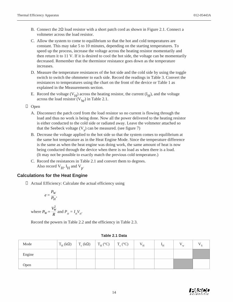
B. Connect the 2Ω load resistor with a short patch cord as shown in Figure 2.1. Connect avoltmeter across the load resistor.
C. Allow the system to come to equilibrium so that the hot and cold temperatures areconstant. This may take 5 to 10 minutes, depending on the starting temperatures. Tospeed up the process, increase the voltage across the heating resistor momentarily andthen return it to 11 V. If it is desired to cool the hot side, the voltage can be momentarilydecreased. Remember that the thermistor resistance goes down as the temperatureincreases.
D. Measure the temperature resistances of the hot side and the cold side by using the toggleswitch to switch the ohmmeter to each side. Record the readings in Table 3. Convert theresistances to temperatures using the chart on the front of the device or Table 1 asexplained in the Measurements section.
E. Record the voltage (VH) across the heating resistor, the current (IH), and the voltageacross the load resistor (VW) in Table 2.1.
➁ Open
A. Disconnect the patch cord from the load resistor so no current is flowing through theload and thus no work is being done. Now all the power delivered to the heating resistoris either conducted to the cold side or radiated away. Leave the voltmeter attached sothat the Seebeck voltage (Vs) can be measured. (see figure 7)
B. Decrease the voltage applied to the hot side so that the system comes to equilibrium atthe same hot temperature as in the Heat Engine Mode. Since the temperature differenceis the same as when the heat engine was doing work, the same amount of heat is nowbeing conducted through the device when there is no load as when there is a load.(It may not be possible to exactly match the previous cold temperature.)
C. Record the resistances in Table 2.1 and convert them to degrees.Also record VH, IH and Vp.
Calculations for the Heat Engine
➀ Actual Efficiency: Calculate the actual efficiency using
e =PW
PH,
where PW =VW
2
R and P
H = I
HV
H.
Record the powers in Table 2.2 and the efficiency in Table 2.3.
012-05443A Thermal Efficiency Apparatus
15
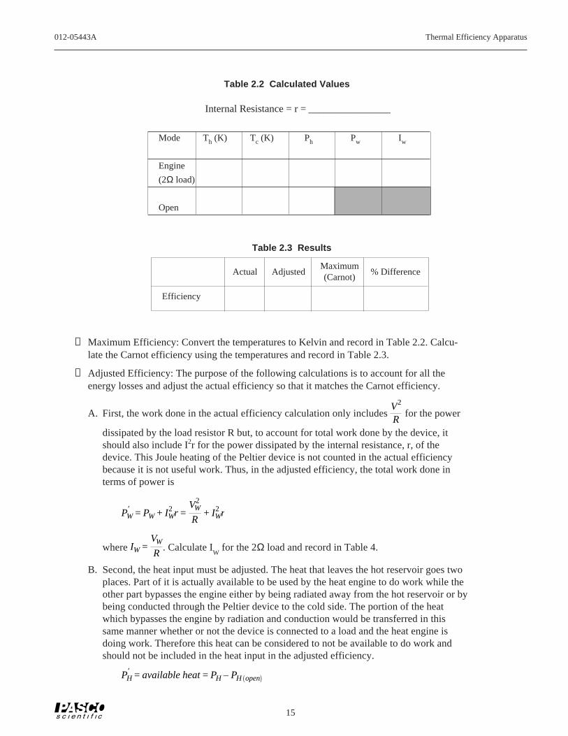
Table 2.3 Results
Maximum(Carnot)
➁ Maximum Efficiency: Convert the temperatures to Kelvin and record in Table 2.2. Calcu-late the Carnot efficiency using the temperatures and record in Table 2.3.
➂ Adjusted Efficiency: The purpose of the following calculations is to account for all theenergy losses and adjust the actual efficiency so that it matches the Carnot efficiency.
A. First, the work done in the actual efficiency calculation only includes V2
R for the power
dissipated by the load resistor R but, to account for total work done by the device, itshould also include I2r for the power dissipated by the internal resistance, r, of thedevice. This Joule heating of the Peltier device is not counted in the actual efficiencybecause it is not useful work. Thus, in the adjusted efficiency, the total work done interms of power is
PW′ = PW + IW
2 r =VW
2
R+ IW
2 r
where IW =VW
R. Calculate I
W for the 2Ω load and record in Table 4.
B. Second, the heat input must be adjusted. The heat that leaves the hot reservoir goes twoplaces. Part of it is actually available to be used by the heat engine to do work while theother part bypasses the engine either by being radiated away from the hot reservoir or bybeing conducted through the Peltier device to the cold side. The portion of the heatwhich bypasses the engine by radiation and conduction would be transferred in thissame manner whether or not the device is connected to a load and the heat engine isdoing work. Therefore this heat can be considered to not be available to do work andshould not be included in the heat input in the adjusted efficiency.
PH′ = available heat = PH – PH open
Table 2.2 Calculated Values
Internal Resistance = r = ________________
Mode Th (K) Tc (K) Ph Pw Iw
Engine
(2Ω load)
Open
Actual Adjusted % Difference
Efficiency

Thermal Efficiency Apparatus 012-05443A
16
The Thermal Efficiency Apparatus is run with a load connected to measure PH (Figure
6) and then the load is disconnected and the power input into the hot reservoir is ad-justed to maintain the temperatures (less power is needed when there is no load sinceless heat is being drawn from the hot reservoir). See Figure 7. P
H(OPEN) is the power
input to the hot reservoir when no load is present. Since, while there is no load, the hotreservoir is maintained at an equilibrium temperature, the heat put into the hot reservoirby the heating resistor must equal the heat radiated and conducted away from the hotreservoir. So measuring the heat input when there is no load determines the heat lossdue to radiation and conduction. It is assumed this loss is the same when there is a loadand the heat engine is operating.
Having accounted for the obvious energy losses, the adjusted efficiency should matchthe Carnot efficiency which assumes no energy loss. The adjusted efficiency is
eadjusted′ =
PW′
PH′ =
PW + IW2 r
PH – PH open
Calculate the internal resistance, r, using the equation
r =VP – VW
VWR
which is derived in the Indirect Measurement section. Record this resistance in Table2.2. Then calculate the adjusted efficiency and record the result in Table 2.3.
Calculate the percent difference between the adjusted efficiency and the Carnot (maxi-mum) efficiency
% Difference =emax – eadjusted
emax× 100%
and record in Table 2.3.
Questions
➀ If the difference between the temperature of the hot side and the cold side was decreased,would the maximum efficiency increase or decrease?
➁ The actual efficiency of this heat engine is very low and yet heat engines of this type areused extensively in remote areas to run things. How can such an inefficient device be ofpractical use?
➂ Calculate the rate of change in entropy for the system which includes the hot and coldreservoirs. Since the reservoirs are at constant temperature, the rate of change in entropy is
∆S∆t
=∆Q / ∆t
T=
PT
for each reservoir. Is the total change in entropy positive or negative? Why?

012-05443A Thermal Efficiency Apparatus
17
Experiment 3: Heat Pump Coefficient of Performance
EQUIPMENT NEEDED:
— Thermal Efficiency Apparatus — 1 DC power supplies capable of 2.5 A at 12 V — patch cords — ohmmeter— ammeter (up to 3 A) — voltmeter— 3 kg — (7 lbs) ice and a bucket for the
ice-water bath
NOTE: Before doing this experiment, it is necessary to perform the HEAT ENGINEEFFICIENCY experiment to get the data necessary to determine the internal resistance ofthe Peltier device.
To complete the measurements for this experiment, use the following instructions to run theapparatus as a heat pump (pumping heat from the cold side to the hot side):
Setup
➀ Prepare the ice-water bath and immerse both rubber tubes from the Thermal EfficiencyApparatus into the bath (Figure 4).
to AC supply
for driving the Peltier device
for measuring temperatures
–+
PowerSupply
Figure 3.1 Heat Pump Mode
for measuring Vw
for measuring Iw
Pw = VwIw
to ice watertub
Ω
A
V

Thermal Efficiency Apparatus 012-05443A
18
➁ Plug the 9V transformer into the wall socket and into the pump on the Thermal EfficiencyApparatus. You should now hear the pump running and water should be coming out of therubber hose marked “out”.
➂ Disconnect the power supply to the hot side. Connect the power supply directly across thePeltier device with no load resistance. See Figure 3.1
➃ Connect an ammeter and a voltmeter to the power supply.
Procedure
➀ Increase the voltage until equilibrium is reached at the same hot temperature as in theprevious experiment. The hot side is now being heated by heat pumped from the cold siderather than the heater resistor.
➁ Record the resistances and convert them to degrees. Also record the voltage (VW) and thecurrent (IW) in Table 3.1.
Analysis
➀ Actual Coefficient of Performance: Calculate the actual COP using the data taken in theHeat Engine experiment.
κ =PC
PW=
PH (OPEN) – PW
PW
Record this result in Table 3.1.
➁ Maximum Coefficient of Performance: Calculate the maximum COP using
κMAX =TC
TH – TC
and record this result in Table 3.1.
➂ Adjusted Coefficient of Performance: Part of the power being applied to the Peltier deviceis being dissipated in the Joule heating of the internal resistance of the device rather thanbeing used to pump the heat from the cold reservoir. Therefore, to adjust for this, I2r mustbe subtracted from the power input to the Peltier device. Then the COP becomes the heatpumped from the cold reservoir divided by work done to pump the heat, rather than divid-ing by the work done to pump the heat and heat the internal resistance. In terms of thepower,
κADJUSTED =PH (OPEN) – PW
PW – IWr2
Record this result in Table 3.1. Calculate the percent difference between the adjusted COPand maximum COP:
% Difference =κMAX – κADJUSTED
κMAX× 100%
and record in Table 3.1.

012-05443A Thermal Efficiency Apparatus
19
Questions
➀ If the difference between the temperature of the hot side and the cold side was decreased,would the maximum COP increase or decrease?
➁ Calculate the rate of change in entropy for the system which includes the hot and coldreservoirs. Since the reservoirs are at constant temperature, the rate of change in entropy is
∆S
∆t=
∆Q / ∆t
T=
PT
for each reservoir. Is the total change in entropy positive or negative? Why?
TH
(kΩ) TC
(kΩ) TH
(K) TC
(K) VW
IW
PW
actual max adj % diffCOP COP COP
Table 3.1 Heat Pump Data and Results

Thermal Efficiency Apparatus 012-05443A
20
Experiment 4: Thermal Conductivity
Introduction
The rate at which heat is conducted through a material of thickness x and cross-sectionalarea A depends on the difference in temperature between the sides (∆T) and the thermalconductivity (k) of the material.
Power =HeatTime
=kA (∆T)
x
For the Thermal Efficiency Apparatus, the Peltier device has 71 couples and each coupleconsists of 2 elements, so there is a total of 142 elements which conduct heat (Figure 9).
Each element has a length to area ratio of 8.460 cm-1. So xA
=8.460cm–1
142. Use the data taken
in Experiment 2 for the Open Mode to calculate the thermal conductivity of the Peltierdevice:
k =PH (OPEN) (x / A)
∆T
Question
➀ How does the thermal conductivity of the Peltier device compare with the thermal conduc-tivity of copper?
Figure 4.1 One Couple Equals Two Elements
Copper
P
N

012-05443A Thermal Efficiency Apparatus
21
Experiment 5: Load for Optimum Performance
EQUIPMENT NEEDED:
— Thermal Efficiency Apparatus— DCpower supply capable of 2.5 A at 12 V— 3 kg (7 lbs) ice and a bucket for the ice-water bath— ohmmeter— ammeter (up to 3 A)— 2 voltmeters— patch cords
Theory
This experiment finds the load resistor which maximizes the power output of the heatengine. The power delivered to the load resistor, R, is P = I2R. The amount of current thatflows through the load resistor varies as the load is varied. From Figure10, VS = I(r+R) where VS is the Seebeck voltage and r is the internal resistance of thePeltier device.
So the power can be expressed in terms of the Seebeck voltage, the internal resistance, andthe load resistance:
P =Vs
r + R
2
R
Assuming the Seebeck voltage remains constant if the temperatures of the hot and coldreservoirs are constant, the power can be maximized with respect to the load resistance bytaking the derivative and setting it equal to zero:
dPdR
=VS
2(r – R)
(r + R)3= 0
This shows that when the load resistance is equal to the internal resistance of the Peltierdevice, the power delivered to the load will be a maximum.
Place endsof tubing inice watertub
Connect to appropriate AC supply(powers pump to circulate ice water)
Ω
A
V
Powersupply
V
Figure 5.2 Connecting the 0.5 Ω load resistor
0.5Ω 2 Ω1 Ω
Vs r
R
Vl
Figure 5.1 Peltier device connectedto a load resistor

Thermal Efficiency Apparatus 012-05443A
22
Procedure
➀ Connect a DC power supply and a voltmeter and ammeter to the heater block terminals.Turn on the voltage to about 11 V.
NOTE: This is just a suggested value chosen to make the hot temperature nearly at themaximum allowed. Any voltage less than 12 V is suitable. The Thermal EfficiencyApparatus should not be run for more than 5 minutes with the hot side above 80°C. Athermal switch will automatically shut off the current to the heater block if it exceeds93°C to prevent damage to the device.
➁ Connect the 0.5W load resistor with a short patch cord as shown in Figure 11. Connect avoltmeter across the load resistor.
NOTE: Alternatively, a variable power resistor (rheostat) may be used in place of the loadresistors supplied with the Thermal Efficiency Apparatus. This has the advantage of beingable to continuously vary the load resistance. However, it will be necessary to measurethe resistance of the load.
➂ Allow the system to come to equilibrium so that the hot and cold temperatures are constant.This may take 5 to 10 minutes, depending on the starting temperatures. To speed up theprocess, increase the voltage across the heating resistor momentarily and then return it to 11V. If it is desired to cool the hot side, the voltage can be momentarily decreased. Rememberthat the thermistor resistance goes down as the temperature increases.
➃ Measure the temperature resistances of the hot side and the cold side by using the toggleswitch to switch the ohmmeter to each side. Record the readings in Table 5.1. Convert theresistances to temperatures using the chart on the front of the device or Table 1 as explainedin the Measurements section.
➄ Record the voltage (VH) across the heating resistor, the current (IH), and the voltage acrossthe load resistor (VW) in Table 5.1.
Table 5.1: Heat Engine Data and Results
R(Ω) TH
(kΩ) TC
(kΩ) TH
(°K) T° (°K) VH
IH
VW
PH
PL
e
0.5
1.0
1.5
2.0
2.5
3.0
3.5

012-05443A Thermal Efficiency Apparatus
23
➅ Calculate the power input to the hot side, PH = IHVH, and the power dissipated by the load
resistor, PL =VW
2
R. Calculate the efficiency, e =
PL
PH. Record all these values in Table 5.1.
➆ Adjust the power input to the hot side to keep the temperature of the hot reservoir at thesame temperature as it was for the 0.5 Ω resistor while Steps 1 through 6 are repeated for theother possible load resistances: 1, 1.5, 2, 2.5, 3, and 3.5 ohms.
Questions
➀ For which load resistor is the efficiency a maximum?
➁ If you have done experiment 2: How does the load resistance for optimum efficiencycompare with the internal resistance measured in that experiment?

Thermal Efficiency Apparatus 012-05443A
24
Notes:

012-05443A Thermal Efficiency Apparatus
25
Teacher’s Guide
Experiment 1: Heat Engine and Temperature Difference
Notes on Setup
➁ It may be necessary to prime the pump by suckingon the output line briefly.
Notes on Calculations
➀ Use the equations PH = VHIH and PW =VW
2
R
➂ efficiency =PW
PH
➃ eCarnot =TH – TC
TH
Notes on Analysis and Questions
B
B
B
B
B
B
B
JJJJJJJ0
0.02
0.04
0.06
0.08
0.1
0.12
0.14
0.16
0.18
0.2
0 10 20 30 40 50 60 70
Effi
cien
cy (
%)
Temperature Difference (°C)
B Carnot Efficiency
J Actual Efficiency
➀ Yes.
➁,➂ Both Carnot and actual efficiency increase withincreasing temperature difference. (for a constantcold temperature)
➃ In these trials, 11-12% of the available energy wasused.
➄ Although the efficiency is low, the reliability is ex-tremely high. (There are no moving parts in thePeltier device.) One practical application of thesedevices is in satellite power supplies. A small pieceof radioactive material is used as a source of heat,and a radiation fin is used as a heat sink. Anothersimilar application is to use the temperature differ-ence between a nuclear isotope and arctic weatherto run a remote unmanned weather station. Any ap-plication where the thermal mass of the availablesources is large, the power requirements are small,and the required reliability is high is good for thePeltier device.

Thermal Efficiency Apparatus 012-05443A
26
Experiment 2: Heat Engine Efficiency (Detailed Study)
Notes on Setup
➁ It may be necessary to prime the pump by suckingon the output line briefly.
Sample Data
Mode Th (°C) Tc (°C) Vh Ih Vw Vs
Engine 57.9 3.5 10.00 2.02 0.890
Open 57.9 3.3 8.99 1.815 1.495
Calculated Values
Mode Th (K) Tc (K) Ph Pw Iw
Engine 330.9 276.5 20.2 0.40 0.45
Open 330.9 276.3 16.3
Internal Resistance: r = 1.36Ω
Results
Actual Adjusted Maximum(Carnot)
% Difference
Efficiency 1.96% 17.13% 16.44% -4.23%
Note that these results were obtained using slightlylower initial voltage than recommended in the lab.In general, mid-range temperatures give betterresults than extremely large or small temperaturedifferences.
Answers to Questions
➀ If the temperature difference was decreased, the ef-ficiency would also decrease.
➁ See experiment 1, question 5.
➂ For the hot reservoir, ∆S/∆t was -0.061. For thecold reservoir, it was 0.073. The total change in en-tropy is positive. In any non-reversible process, theentropy will increase.

012-05443A Thermal Efficiency Apparatus
27
Experiment 3: Heat Pump Coefficient of Performance
Typical Results
Note that values of Ph and r were taken fromexperiment 2.
Th (K) Tc (K) Vw Iw Pw COP COPmax COPadj % diff
330.9 275.5 3.64 1.63 5.93 1.75 4.97 4.48 9.9%
Answers to Questions
➀ The COP increases when the difference in tempera-ture decreases.
➁ For the hot reservoir, ∆S/∆t = +0.018. For the coldreservoir, it is – 0.0215. The net change in entropyis negative. Work is done by the heat pump to de-crease the entropy.
Experiment 4: Thermal Conductivity
Answer to Questions
➀ The thermal conductivity, based on the data takenin experiment 2 of this guide, is 1.79 Watt/mK. Bycomparison, the thermal conductivity of copper (at273 K) is 401 Watt/mK.
The Peltier device is made of Bismuth Telluride,which has an accepted thermal conductivity ofapproximately 1.6 Watt/mK
Thermal Efficiency Apparatus 012-05443A
28
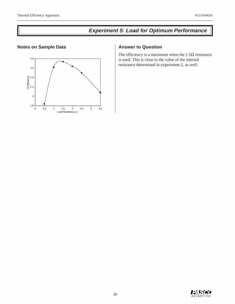
Experiment 5: Load for Optimum Performance
Notes on Sample Data
1
1
1
1
1
1
1.9
2
2.1
2.2
2.3
2.4
0 0.5 1 1.5 2 2.5 3 3.5
% E
ffici
ency
Load Resistance ( )
Answer to Question
The efficiency is a maximum when the 1.5Ω resistanceis used. This is close to the value of the internalresistance determined in experiment 2, as well.

012-05443A Thermal Efficiency Apparatus
29
Contacting Technical Support
Before you call the PASCO Technical Support staff itwould be helpful to prepare the following information:
• If your problem is with the PASCO apparatus, note:
Title and Model number (usually listed on the label).
Approximate age of apparatus.
A detailed description of the problem/sequence ofevents. (In case you can't call PASCO right away,you won't lose valuable data.)
If possible, have the apparatus within reach whencalling. This makes descriptions of individual partsmuch easier.
• If your problem relates to the instruction manual,note:
Part number and Revision (listed by month and yearon the front cover).
Have the manual at hand to discuss your questions.
Feed-Back
If you have any comments about this product or thismanual please let us know. If you have any sugges-tions on alternate experiments or find a problem in themanual please tell us. PASCO appreciates any cus-tomer feed-back. Your input helps us evaluate andimprove our product.
To Reach PASCO
For Technical Support call us at 1-800-772-8700 (toll-free within the U.S.) or (916) 786-3800.
Technical Support