THERMAL ANALYSIS OF SILENCER PIPE - iaeme. · PDF fileStudy of design of existing silencer ......
10
http://www.iaeme.com/IJMET/index.asp 269 [email protected] International Journal of Mechanical Engineering and Technology (IJMET) Volume 8, Issue 3, March 2017, pp. 269–278 Article ID: IJMET_08_03_030 Available online at http://www.iaeme.com/IJMET/issues.asp?JType=IJMET&VType=8&IType=3 ISSN Print: 0976-6340 and ISSN Online: 0976-6359 © IAEME Publication Scopus Indexed THERMAL ANALYSIS OF SILENCER PIPE A. S. Mate Mechanical Engineering Department, Pillai HOC College of Engineering & Technology, Rasayani, Raigad - 410207, Maharashtra, India V. Kumbhar Mechanical Engineering Department, Pillai College of Engineering & Technology, New Panvel, Raigad - 410206, Maharashtra, India ABSTRACT Automotive and heavy machineries engines in industries have exhaust system which is pivotal in rejecting the exhaust air, heat which increases air pollution, exhausting speed increases noise pollution, human harmful atmospheric environment which may be required to prevent and preserve harmful atmospheric gases. The silencer is required to control air pollution, noise pollution, to filter (Catalytic converter) the chemical toxic elements. The function of exhaust system to discharge the exhaust gases of the engines which will not affect atmospheric environment. This study deals with an investigation of hotspots or areas where the temperature concentrations take place for example such as mating areas between two pipes. Temperatures at different points on the silencer are determined by experimental setup on a car further considering the results of temperatures geometric modelling is done on the current model of silencer in ABAQUS and stress analysis is done on the same. The main objective is to reduce the hotspots in the silencer thus improving the efficiency of heat transfer and also improving the life span of the silencer. From this report we can establish a relation between the exhaust gas temperatures and stresses developed, modified design is proposed. Key words: Silencer, Temperature Concentrations, Reduce Hotspots Cite this Article: A. S. Mate and V. Kumbhar, Thermal Analysis of Silencer Pipe, International Journal of Mechanical Engineering and Technology, 8(3), 2017, pp.269– 278. http://www.iaeme.com/IJMET/issues.asp?JType=IJMET&VType=8&IType=3
-
Upload
nguyenthuan -
Category
Documents
-
view
221 -
download
5
Transcript of THERMAL ANALYSIS OF SILENCER PIPE - iaeme. · PDF fileStudy of design of existing silencer ......

http://www.iaeme.com/IJMET/index.asp 269 [email protected]
International Journal of Mechanical Engineering and Technology (IJMET) Volume 8, Issue 3, March 2017, pp. 269–278 Article ID: IJMET_08_03_030
Available online at http://www.iaeme.com/IJMET/issues.asp?JType=IJMET&VType=8&IType=3
ISSN Print: 0976-6340 and ISSN Online: 0976-6359
© IAEME Publication Scopus Indexed
THERMAL ANALYSIS OF SILENCER PIPE
A. S. Mate
Mechanical Engineering Department,
Pillai HOC College of Engineering & Technology,
Rasayani, Raigad - 410207, Maharashtra, India
V. Kumbhar
Mechanical Engineering Department,
Pillai College of Engineering & Technology,
New Panvel, Raigad - 410206, Maharashtra, India
ABSTRACT
Automotive and heavy machineries engines in industries have exhaust system which
is pivotal in rejecting the exhaust air, heat which increases air pollution, exhausting
speed increases noise pollution, human harmful atmospheric environment which may
be required to prevent and preserve harmful atmospheric gases. The silencer is required
to control air pollution, noise pollution, to filter (Catalytic converter) the chemical toxic
elements. The function of exhaust system to discharge the exhaust gases of the engines
which will not affect atmospheric environment.
This study deals with an investigation of hotspots or areas where the temperature
concentrations take place for example such as mating areas between two pipes.
Temperatures at different points on the silencer are determined by experimental setup
on a car further considering the results of temperatures geometric modelling is done on
the current model of silencer in ABAQUS and stress analysis is done on the same.
The main objective is to reduce the hotspots in the silencer thus improving the
efficiency of heat transfer and also improving the life span of the silencer. From this
report we can establish a relation between the exhaust gas temperatures and stresses
developed, modified design is proposed.
Key words: Silencer, Temperature Concentrations, Reduce Hotspots
Cite this Article: A. S. Mate and V. Kumbhar, Thermal Analysis of Silencer Pipe,
International Journal of Mechanical Engineering and Technology, 8(3), 2017, pp.269–
278.
http://www.iaeme.com/IJMET/issues.asp?JType=IJMET&VType=8&IType=3

Thermal Analysis of Silencer Pipe
http://www.iaeme.com/IJMET/index.asp 270 [email protected]
1. INTRODUCTION
The hot gases from the combustion chamber pass through the automotive exhaust system and
come in contact with high temperatures. In order to increase the life of the exhaust system
components, the heat distribution should be uniform. To design the exhaust system it is very
important to understand the physical phenomenon which takes place in the exhaust system. By
controlling the exhaust gas temperature, normal operating conditions can be achieved and it
also enhances the performance of the engine. The heat transfer analysis of automotive exhaust
system is reviewed in this article. Dattatray Dilip Giripunje (2013) established that to reduce
the temperature and backpressure, silencer remodeling is suggested in such a way that the
transmission loss is reduced to 30 dB and there is also reduction of backpressure to 10. Mesut
Durat (2014) presents that by performing CFD analysis the optimal positioning of the catalyst
is determined. Mayuri Chourey (2014) suggested that from analysis that Carbon fibre material
can be used which demonstrates enormous non corrosive properties. Agron E. Gjinolli (2015)
developed a method to select and determine the optimal duct design that can be used along with
its shell thicknesses, mounting points, expansion joint locations /requirements, and loads on the
supporting structures can also be reviewed as well as the results of the final design. Mahesh S.
Vasava (2015) it can be concluded from the paper that exhaust gas temperature directly affects
the performance of engine and in order to improve the performance of the engine it is necessary
to control the exhaust temperature. S.Balamurugan (2015) mentioned that the baffle
arrangement is used in the muffler to eliminate tremendous amount of toxic exhaust that is
released from the engine as well as it also reduces the usage of fuel by 0.5%. Lakshminarayanan
(2015) established that the comparison of various factors affecting the muffler such as thermal
concentration, thermal stress and properties of material are taken in to account and analyzed in
the software and input is taken from experimental setup. Based on that optimal redesigning and
remodeling is made to the muffler. Silencer is an integral part of all the exhaust systems which
have hot gas discharges at relatively high velocities. The silencer is induced with several
stresses due to heat and other factors, such as vibration, fatigue which it has to withstand. The
enhancement of the function of the silencer is increased directly as we make improvements in
the silencer which also improves its effective life span.
Figure 1 Silencers
(Source: Complete Book on Production of Automobile Components & Allied Products NIIR
Publication)

A. S. Mate and V. Kumbhar
http://www.iaeme.com/IJMET/index.asp 271 [email protected]
The exhaust system is also affected by factors such as backpressure and noise. The
maximum allowable engine backpressure is specified by the engine manufacturer. Increase in
backpressure gives rise to problems such as pumping work, reduced intake manifold boost
pressure, cylinder scavenging and turbocharger problems. The usage of silencers and mufflers
helps in reducing the engine exhaust noise. The function of the exhaust system is to carry the
harmful exhaust gases and discharge them quickly with reduced noise.
In context with the above the design considerations for the system are as follows:
1. To keep the backpressure within the specified limits as specified for the particular engine model
and to provide maximum efficiency we have to reduce the resistance to gas flow (backpressure).
2. Noise emission levels should not exceed the local regulations and application requirements.
3. To reduce the impact of high exhaust temperatures on engine components, an adequate
clearance should be provided.
4. To make sure that the life of the engine components is not reduced due to overstressing of engine
components such as turbocharger and manifolds with excess weight.
5. To select proper components for exhaust system that will reject heat as intended by the original
design.
The main Components in engine exhaust system are as follows:
Exhaust manifolds or EKE.
Catalytic converters.
Muffler (Silencer).
2. MAIN COMPONENTS OF SILENCER
2.1. Exhaust Manifold
The function of the exhaust manifold is to carry the hot exhaust gases and release them to the
environment through proper exhaust outlet. Backpressure and turbulence should be minimum
in the designed manifold. There are three types of manifolds such as dry, water-cooled and air
shielded water cooled manifold designs selected on the basis of application and design
requirements. Types of manifolds are as follows.
1. Dry Manifolds
2. Water-cooled Manifolds
3. Air Shielded Water-cooled Manifolds.
Figure 2 Manifolds
(Source: Performance Exhaust Systems, CarTech; 1publication)
Thermal Analysis of Silencer Pipe
http://www.iaeme.com/IJMET/index.asp 272 [email protected]
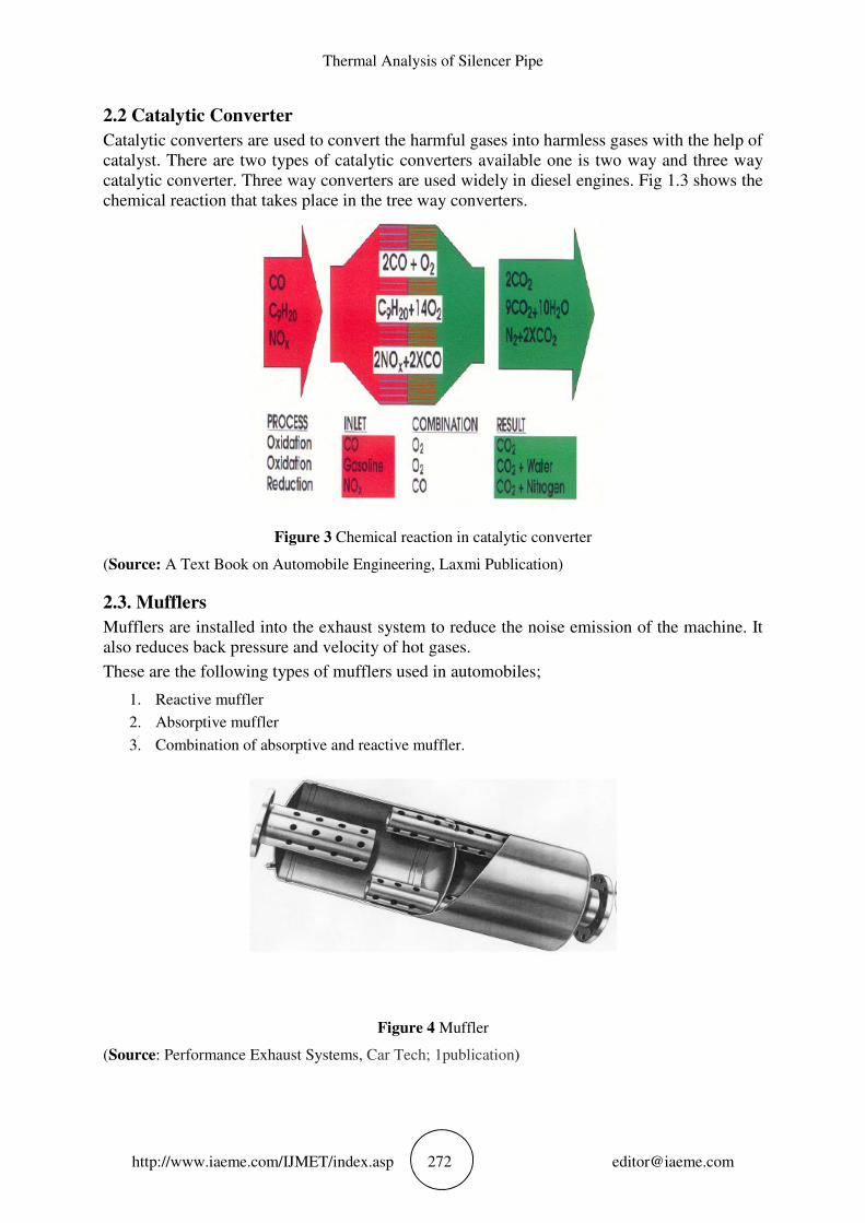
2.2 Catalytic Converter
Catalytic converters are used to convert the harmful gases into harmless gases with the help of
catalyst. There are two types of catalytic converters available one is two way and three way
catalytic converter. Three way converters are used widely in diesel engines. Fig 1.3 shows the
chemical reaction that takes place in the tree way converters.
Figure 3 Chemical reaction in catalytic converter
(Source: A Text Book on Automobile Engineering, Laxmi Publication)
2.3. Mufflers
Mufflers are installed into the exhaust system to reduce the noise emission of the machine. It
also reduces back pressure and velocity of hot gases.
These are the following types of mufflers used in automobiles;
1. Reactive muffler
2. Absorptive muffler
3. Combination of absorptive and reactive muffler.
Figure 4 Muffler
(Source: Performance Exhaust Systems, Car Tech; 1publication)

A. S. Mate and V. Kumbhar
http://www.iaeme.com/IJMET/index.asp 273 [email protected]
3. DATA COLLECTION AND ANALYSIS
The methodology to find the solution for the current work adopted is as follows.By measuring
temperatures at the points using experimental set up on the silencer, then stress distribution for
those temperatures is found out by software. The steps followed to complete the project work
are in the form of flow chart.
Figure 5 Temperature at various points in the silencer.
Study of exhaust system and list out the Performance
parameters
Study of design of existing silencer
Analysis of existing silencer for `thermal’ (heat
dissipation)
Geometry modelling of existing silencer
Demonstrating a relation between exhaust gas
temperature and stress caused due to it.

Thermal Analysis of Silencer Pipe
http://www.iaeme.com/IJMET/index.asp 274 [email protected]
Temperatures are recorded at critical locations of silencer .Muffler section are critical as
real-time temperatures are difficult to get. They are obtained by remote probe of temperature
recorder, with thermocouple at each of section of the silencer, approximately 4 locations are
fixed for temperatures and temperatures recorded. The temperatures are recorded at exhaust
manifolds, at middle of the silencer, before the muffler, at the muffler and at the exhaust of
silencer. The following table shows the recorded temperatures.
Table 1 Observation of temperature of exhaust system at different location and measurements of
temperature at those locations.
Sr .No Measuring Points T1 T2 T3 T4
Temperature at Starting of the Engine
1. Manifold 1 66 65 65 70
2. Manifold 2 70 71 70 70
3. Manifold 3 75 73 75 76
4. Manifold 4 75 76 74 75
5. Temperature at combination point of 4 manifolds 59 58 59 60
6. Temperature at middle of silencer 51 49 50 49
7. Temperature of silencer before muffler 46 47 47 46
8. Temperature of muffler 46 45 46 46
9. Temperature of silencer before exhaust to atmosphere 46 46 46 45
Temperature at Steady State
1. Manifold 1 85 86 86 87
2. Manifold 2 92 92 93 93
3. Manifold 3 97 97 98 99
4. Manifold 4 98 99 100 101
5. Temperature at combination point of 4 manifolds 82 82 83 84
6. Temperature at middle of silencer 65 64 64 64
7. Temperature of silencer before muffler 59 59 58 58
8. Temperature of muffler 56 55 55 54
9. Temperature of silencer before exhaust to atmosphere 53 53 52 51
The experimental data is then used with FEM package for creation of temperature field for
the silencer pipe, muffler pipe and muffler assembly. The analysis software used is ABAQUS.
The Flow of analysis is as follows:
The different material properties selected for silencer are as:
Young’s modulus of Elasticity E = 2e ^ 11 N\m2
Poisson ratio = 0.3, material density is = 7700 kg/m3,
Thermal conductivity=237 W\m k, coefficient of expansion =1.33e-005 and
The length of silencer is = 500 mm.
Materials used for silencer is alloy steel.

A. S. Mate and V. Kumbhar
http://www.iaeme.com/IJMET/index.asp 275 [email protected]
• Model and meshing of silencer pipe
Figure 6 Model of silencer pipe
The above figure shows model of silencer in solid works by selecting the tool circle then
create section and loft.
Figure 7 Meshing of silencer pipe
The above figure shows the meshing of the silencer pipe

Thermal Analysis of Silencer Pipe
http://www.iaeme.com/IJMET/index.asp 276 [email protected]
• Analysis result of silencer pipe
Figure 8 Vonmises stress
The above figure shows the amount of von misses stress acting along the surface of the
silencer pipe.
Figure 9 Maximum principal stress
The above figure shows the magnitude of maximum principle stress along the surface of
silencer pipe.
A. S. Mate and V. Kumbhar
http://www.iaeme.com/IJMET/index.asp 277 [email protected]
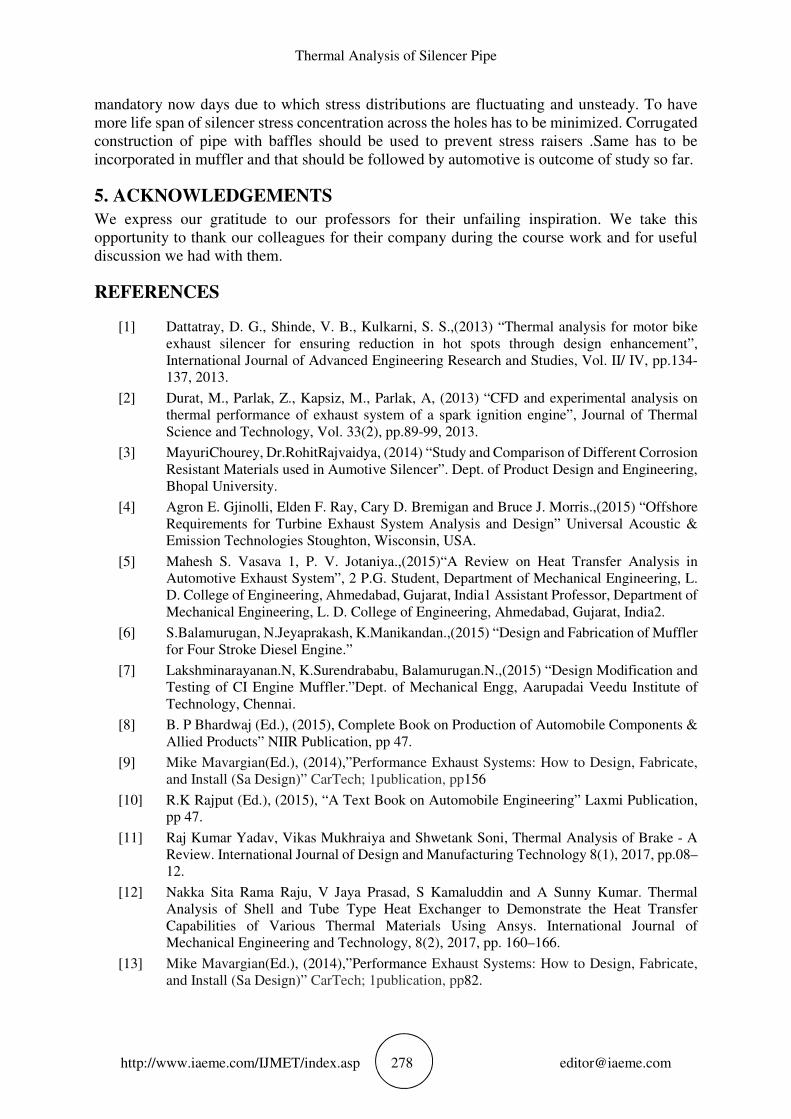
Figure 10 Minimum principal stress
The above figure shows the magnitude of minimum principle stress along the surface of
silencer pipe.
Figure 11 Strain magnitude
4. CONCLUSION
Analysis is done for silencer pipe, muffler pipe and muffler assembly .From the analysis it is
observed that the stress concentration is at the periphery of the holes of the muffler. So we can
say that stress raising sections are dominant over muffler region because of holes, which are
Thermal Analysis of Silencer Pipe
http://www.iaeme.com/IJMET/index.asp 278 [email protected]
mandatory now days due to which stress distributions are fluctuating and unsteady. To have
more life span of silencer stress concentration across the holes has to be minimized. Corrugated
construction of pipe with baffles should be used to prevent stress raisers .Same has to be
incorporated in muffler and that should be followed by automotive is outcome of study so far.
5. ACKNOWLEDGEMENTS
We express our gratitude to our professors for their unfailing inspiration. We take this
opportunity to thank our colleagues for their company during the course work and for useful
discussion we had with them.
REFERENCES
[1] Dattatray, D. G., Shinde, V. B., Kulkarni, S. S.,(2013) “Thermal analysis for motor bike
exhaust silencer for ensuring reduction in hot spots through design enhancement”,
International Journal of Advanced Engineering Research and Studies, Vol. II/ IV, pp.134-
137, 2013.
[2] Durat, M., Parlak, Z., Kapsiz, M., Parlak, A, (2013) “CFD and experimental analysis on
thermal performance of exhaust system of a spark ignition engine”, Journal of Thermal
Science and Technology, Vol. 33(2), pp.89-99, 2013.
[3] MayuriChourey, Dr.RohitRajvaidya, (2014) “Study and Comparison of Different Corrosion
Resistant Materials used in Aumotive Silencer”. Dept. of Product Design and Engineering,
Bhopal University.
[4] Agron E. Gjinolli, Elden F. Ray, Cary D. Bremigan and Bruce J. Morris.,(2015) “Offshore
Requirements for Turbine Exhaust System Analysis and Design” Universal Acoustic &
Emission Technologies Stoughton, Wisconsin, USA.
[5] Mahesh S. Vasava 1, P. V. Jotaniya.,(2015)“A Review on Heat Transfer Analysis in
Automotive Exhaust System”, 2 P.G. Student, Department of Mechanical Engineering, L.
D. College of Engineering, Ahmedabad, Gujarat, India1 Assistant Professor, Department of
Mechanical Engineering, L. D. College of Engineering, Ahmedabad, Gujarat, India2.
[6] S.Balamurugan, N.Jeyaprakash, K.Manikandan.,(2015) “Design and Fabrication of Muffler
for Four Stroke Diesel Engine.”
[7] Lakshminarayanan.N, K.Surendrababu, Balamurugan.N.,(2015) “Design Modification and
Testing of CI Engine Muffler.”Dept. of Mechanical Engg, Aarupadai Veedu Institute of
Technology, Chennai.
[8] B. P Bhardwaj (Ed.), (2015), Complete Book on Production of Automobile Components &
Allied Products” NIIR Publication, pp 47.
[9] Mike Mavargian(Ed.), (2014),”Performance Exhaust Systems: How to Design, Fabricate,
and Install (Sa Design)” CarTech; 1publication, pp156
[10] R.K Rajput (Ed.), (2015), “A Text Book on Automobile Engineering” Laxmi Publication,
pp 47.
[11] Raj Kumar Yadav, Vikas Mukhraiya and Shwetank Soni, Thermal Analysis of Brake - A
Review. International Journal of Design and Manufacturing Technology 8(1), 2017, pp.08–
12.
[12] Nakka Sita Rama Raju, V Jaya Prasad, S Kamaluddin and A Sunny Kumar. Thermal
Analysis of Shell and Tube Type Heat Exchanger to Demonstrate the Heat Transfer
Capabilities of Various Thermal Materials Using Ansys. International Journal of
Mechanical Engineering and Technology, 8(2), 2017, pp. 160–166.
[13] Mike Mavargian(Ed.), (2014),”Performance Exhaust Systems: How to Design, Fabricate,
and Install (Sa Design)” CarTech; 1publication, pp82.