Theory of turbo machinery / Turbomaskinernas teori … / Kraftverksteknik / JK A real engine…...
27
Theory of turbo machinery / Turbomaskinernas teori Gas turbines
Transcript of Theory of turbo machinery / Turbomaskinernas teori … / Kraftverksteknik / JK A real engine…...

Theory of turbo machinery / Turbomaskinernas teori
Gas turbines

LTH / Kraftverksteknik / JK
Gas turbineVolvo VT 4400
– Fuel: Natural Gas– P = 12.5– Tin = 660 K– Massflow = 20 kg/s

LTH / Kraftverksteknik / JK
Simple Cycle
Compressor
h
Expander
s
p1
p2
Air
Combustor
Fuel

LTH / Kraftverksteknik / JK
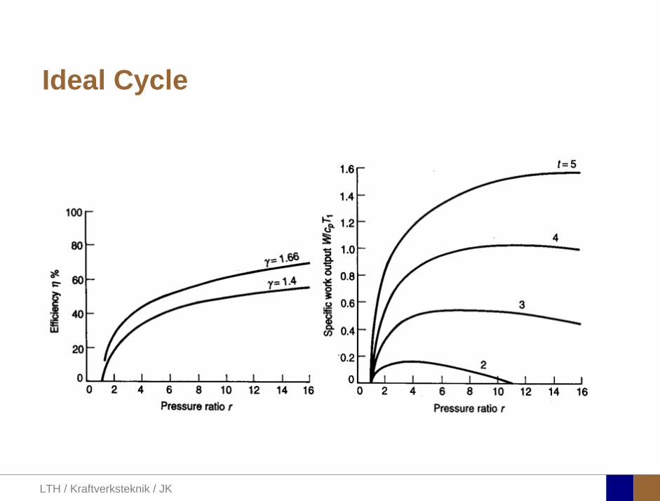
Ideal Cycle
a) Compression and expansion are reversible and adiabatic, i.e. isentropic
b) The change of kinetic energy of the working fluid between the inlet and outlet of each component is negligable.
c) Pressure losses are neglected.d) The working fluid is the same in the entire cycle and it is a
perfect gas with constant specific heats.e) The mass flow of gas is the same throughout the cyclef) The heat-exhanger is a counterflow type with “complete”
heat transfer

LTH / Kraftverksteknik / JK
Ideal Cycle
0ΔQ h W= +
( ) ( ) ( )12 02 01 2 1 2 1pW h h h h c T T= − − = − − = − −
( ) ( )23 3 2 3 2pQ h h c T T= − = −
( ) ( )34 3 4 3 4pW h h c T T= − = −
Compressor
Combustor
Expander (turbine)
steady flow energy equation

LTH / Kraftverksteknik / JK
Ideal Cycle
( )1 32
1 4
TT rT T
γ γ−= =
32
1 4
pprp p
= =where r is pressure ratio
The efficiency equals the ratio of net work output and supplied heat
( ) ( )( )
3 4 2 134 12
23 3 2
p p
p
c T T c T TW WQ c T T
η− − −−
= =−
Cycle efficiancy

LTH / Kraftverksteknik / JK
Ideal Cycle
( ) ( )4
14 1 1 1
24 4 22
1 1 1
111 1 1 1
1 1
TT T T T
T rT T TTT T T
γ γ
η−
⎛ ⎞−⎜ ⎟− ⎛ ⎞⎝ ⎠= − = − = − = − ⎜ ⎟⎛ ⎞ ⎛ ⎞ ⎝ ⎠− −⎜ ⎟ ⎜ ⎟
⎝ ⎠ ⎝ ⎠
i.e. a function of r and γ only!

LTH / Kraftverksteknik / JK
Ideal Cycle
( ) ( )( )
( )( )13 4 2 1 31
1 1 1
11 1P
T T T T TW rc T T T r
γ γγ γ
−−
− − − ⎛ ⎞= = − − −⎜ ⎟⎝ ⎠
( ) ( )34 12 3 4 2 1p pW W W c T T c T T= − = − − −
Normalising with 1PC T
Net work
3
1
T tT
=
LTH / Kraftverksteknik / JK
Ideal Cycle

LTH / Kraftverksteknik / JK
Recuperated Cycle
Compressor Expander
Heat Exchanger

LTH / Kraftverksteknik / JK
Evaporative Cycle
Compressor Expander
Liquid water
Evaporator

LTH / Kraftverksteknik / JK
O2 fired cycle Cycle
ASU
Air
O2
N2
Compressor Expander
EGR

LTH / Kraftverksteknik / JK
H2 fired Cycle
Reformer
Air
CmHnH2O(Air)
Compressor Expander
H2, CO2, (N2)
CO2Separation
Combustor
H2 (N2)

LTH / Kraftverksteknik / JK
Recuperated Cycle

LTH / Kraftverksteknik / JK
Recuperated Cycle

LTH / Kraftverksteknik / JK
Physics of combustion
• Spray formation• Evaporation• Mixing• Ignition• Combustion• Emission formation• Temperature
distribution• ……..
Air blast atomizer, diffusion combustion

LTH / Kraftverksteknik / JK
Schematic combustor
FUEL INJECTOR
DILUTION ZONE
AIR
DIFFUSERAIR SWIRLER
COOLING SLOTAIR CASING
LINER
INTERMEDIATE ZONE
PRIMARY ZONE

LTH / Kraftverksteknik / JK
Spray formation, breakup and vaporization in cross-flow duct typical for LPP modules
LPP module of VT4400

LTH / Kraftverksteknik / JK
Combined cycles
Magnus Genrup 19
Steam Turbine (condensing)
100 % fuel
15 °CGas Turbine
2-pressure HRSG
520…540 °C
27 °C
31 °C
Courtesy to Alstom

LTH / Kraftverksteknik / JK
Type of propulsion plant
2009-10-12 Magnus Genrup 20
Rolls-Royce, The Jet Engine

LTH / Kraftverksteknik / JK
Whittle W1
2009-10-12 Magnus Genrup 21

LTH / Kraftverksteknik / JK
TurbojetRolls-Royce Olympus
2009-10-12 Magnus Genrup 22

LTH / Kraftverksteknik / JK
JAS Gripen engine - RM12
2009-10-12 Magnus Genrup 23
Courtesy to Volvo Aero

LTH / Kraftverksteknik / JK
Turboprop
2009-10-12 Magnus Genrup 24

LTH / Kraftverksteknik / JK
Rolls-Royce Trent 500A340-500/600
2009-10-12 Magnus Genrup 25

LTH / Kraftverksteknik / JK
HSS Passenger shipsSiemens SGT-500
2009-10-12 Magnus Genrup 26
Stena Carisma
Luciano FedericoSiemens SGT-500

LTH / Kraftverksteknik / JK
A real engine…
2009-10-12 Magnus Genrup 27
Opt pressure ratio’sCOT=1643K
• S/C η: 25.06
• C/C η: 18:08
• Spec. work: 14.36
2 stage compressor turbine, rotor blade temp <900°C, COT-SOT = 70°C
.3
.32
.34
.36
.38
.4
Ther
mal
Effi
cien
cy
300 350 400 450 500
Specific Power [kW/(kg/s)]
Pressure Ratio = 10 ... 26 Burner Exit Temperature = 1473 ... 1773 [K]
147
3
152
3
157
3
162
3
167
3
172
3
177
3
0.51 0.52
0.53
0.54
0.55
0.56
Dotted Lines = (PWSD*0.985*0.985+cp_val7)/(WF* [g/(kN*s)]
10
12
14
16
18
20 22
24 26 WCLTq2 iterated for T_m_T=1173ZW2Rstd iterated for W2=100WCLNq2 iterated for cp_val1=70
Example!ηcc