Theory of Time
91
The International Journal of Engineering And Science (IJES) ||Volume|| 4 ||Issue|| 2 ||Pages|| PP.116-206 ||2015|| ISSN: 2319 – 1813 ISBN: 2319 – 1805 www.theijes.com The IJES Page 116 Theory of Time (System theory) K. Ramkumar BE Scholar, Mechanical Engineer, S/o M. Krishnan, Door No. 1/84, Anuppur Po, Salem Dt., Tamil Nadu, India. Email: [email protected] --------------------------------------------------------ABSTRACT----------------------------------------------------------- “Theory of Time” is a research and analysis report on integrated transformation system to find out reason for changes. I had found some systematic relational imbalance among the principles of AC Transformer, Ohm’s law, series parallel circuits and law of conservation of energy. I did systematic analysis and research on above said combination principles and System’s Relative components are determined and organized systematically for better understanding and reformed results are meeting with the natural principles of system. I did systematic analysis on electro-magnetic circuits to understand the structure of the transformation system. Law of conservation of energy, Transformer’s principles, Newton’s laws and Ohm’s law are base for this theory. By doing relational analysis I could derive Equivalent mechanical transformation principles from Electricity Transformation principles and mechanical resistance to transformation equation has been successfully formulated. Finally Obtained / reformed results are compared with our practical science and found that the derived principles are meeting with the natural principles of system and its transformation process. Further, explaining about “how the time is running?”; “what are all the relative components of the time?”; Whether is it possible to stop the time running process? Keywords- Universal transformation system, time (time storage, live time running), energy with power, 3D transformation system, Mechanical Resistance, Newton’s 3 rd Law under transformation, number of individuals available inside the system, past, present and future conditions, loop system, particles in processing state, Energy with power adding and dividing processes, electro-magnetism, work done, Power-Force relation, life. ------------------------------------------------------------------------------------------------------------------------------------- Date of Submission: 23.Feb.2015, Date of Publication: 06-Mar 2015 ------------------------------------------------------------------------------------------------------------------------------------- 1. INTRODUCTION ‗Theory of Time‘ is a systematic analysis report among the principles of electricity, mechanical and universal system. I have found systematic imbalance between Ohm‘s law and Series, parallel circuits with respect to time. Resistance is constant in Ohm‘s law; Voltage is constant in series circuits and ampere is constant in parallel circuits; here, the relational properties are not linked systematically and logics are not fully evolved with respect to transformation system. Here I used systematic approach to relate each other and equivalent ‗series - parallel‘ principles derived from AC Transformer‘s principles without consideration of any constant and used for analyzing all form of series, parallel circuits like electricity, magnet, capacitor, mechanical, water energy cycle, atoms etc. with time linkage. Here Ohm‘s law is not used for analyzing series, parallel electricity circuits under transformation and Ohm‘s law is linked / merged with each and every individual‘s transformation properties inside the universal transformation system. I used combination of Electro-Mechanical principles for analyzing Energy with Power transformation process. Please do reverse analysis/ engineering for better understanding. This is single theory and named ―Theory of Time‖. Nothing can be done without time and confirmed that the energy with power transformation is required to do something. Our interpretation with respect to ―theory of nature‖ must have least or zero deviation to understand the system of nature. Here, I tried up to my knowledge to get actual results of system using practical and theoretical analysis and I have introduced systematic logics to do examine and to take prompt decision on system with 100%. I took ~ 15 years to complete this thesis. Relational properties between the all kinds of transformation systems have been evolved and organized systematically to make clarification on system of transformation for taking prompt decision. Since, this theory is dealing the existing theory of science with different angle and giving more clarification on system. Newton‘s Laws, Ohm‘s law, Law of conservation of energy and AC Transformer‘s principles are base for this theory. This theory is giving more clarification on systematic linkage between everything without any controversy. Thanks to Honorable Sir Isaac Newton and Mr. Georg Simon Ohm. 2. ANALYSIS ON MECHANISM OF ELECTRICITY Ohm‘s law and principles of series parallel circuits compared as explained below. According to Ohms law: ―Ohm's law states that the current through a conductor between two points is directly proportional to the
-
Upload
theijes -
Category
Technology
-
view
219 -
download
0
Transcript of Theory of Time
The International Journal of Engineering And Science (IJES)
||Volume|| 4 ||Issue|| 2 ||Pages|| PP.116-206 ||2015||
ISSN: 2319 – 1813 ISBN: 2319 – 1805
www.theijes.com The IJES Page 116
Theory of Time (System theory)
K. Ramkumar BE Scholar, Mechanical Engineer, S/o M. Krishnan, Door No. 1/84, Anuppur Po, Salem Dt., Tamil Nadu, India.
Email: [email protected]
--------------------------------------------------------ABSTRACT-----------------------------------------------------------
“Theory of Time” is a research and analysis report on integrated transformation system to find out reason for
changes. I had found some systematic relational imbalance among the principles of AC Transformer, Ohm’s
law, series parallel circuits and law of conservation of energy. I did systematic analysis and research on above
said combination principles and System’s Relative components are determined and organized systematically for
better understanding and reformed results are meeting with the natural principles of system.
I did systematic analysis on electro-magnetic circuits to understand the structure of the transformation system.
Law of conservation of energy, Transformer’s principles, Newton’s laws and Ohm’s law are base for this theory. By doing relational analysis I could derive Equivalent mechanical transformation principles from
Electricity Transformation principles and mechanical resistance to transformation equation has been
successfully formulated. Finally Obtained / reformed results are compared with our practical science and found
that the derived principles are meeting with the natural principles of system and its transformation process.
Further, explaining about “how the time is running?”; “what are all the relative components of the time?”;
Whether is it possible to stop the time running process?
Keywords- Universal transformation system, time (time storage, live time running), energy with power, 3D
transformation system, Mechanical Resistance, Newton’s 3rd Law under transformation, number of individuals
available inside the system, past, present and future conditions, loop system, particles in processing state,
Energy with power adding and dividing processes, electro-magnetism, work done, Power-Force relation, life.
------------------------------------------------------------------------------------------------------------------------------------- Date of Submission: 23.Feb.2015, Date of Publication: 06-Mar 2015
-------------------------------------------------------------------------------------------------------------------------------------
1. INTRODUCTION ‗Theory of Time‘ is a systematic analysis report among the principles of electricity, mechanical and universal
system. I have found systematic imbalance between Ohm‘s law and Series, parallel circuits with respect to time.
Resistance is constant in Ohm‘s law; Voltage is constant in series circuits and ampere is constant in parallel
circuits; here, the relational properties are not linked systematically and logics are not fully evolved with respect
to transformation system. Here I used systematic approach to relate each other and equivalent ‗series - parallel‘
principles derived from AC Transformer‘s principles without consideration of any constant and used for
analyzing all form of series, parallel circuits like electricity, magnet, capacitor, mechanical, water energy cycle,
atoms etc. with time linkage. Here Ohm‘s law is not used for analyzing series, parallel electricity circuits under
transformation and Ohm‘s law is linked / merged with each and every individual‘s transformation properties
inside the universal transformation system.
I used combination of Electro-Mechanical principles for analyzing Energy with Power transformation process. Please do reverse analysis/ engineering for better understanding. This is single theory and named ―Theory of
Time‖. Nothing can be done without time and confirmed that the energy with power transformation is required
to do something. Our interpretation with respect to ―theory of nature‖ must have least or zero deviation to
understand the system of nature. Here, I tried up to my knowledge to get actual results of system using practical
and theoretical analysis and I have introduced systematic logics to do examine and to take prompt decision on
system with 100%.
I took ~ 15 years to complete this thesis. Relational properties between the all kinds of transformation systems
have been evolved and organized systematically to make clarification on system of transformation for taking
prompt decision. Since, this theory is dealing the existing theory of science with different angle and giving more
clarification on system. Newton‘s Laws, Ohm‘s law, Law of conservation of energy and AC Transformer‘s
principles are base for this theory. This theory is giving more clarification on systematic linkage between
everything without any controversy. Thanks to Honorable Sir Isaac Newton and Mr. Georg Simon Ohm.
2. ANALYSIS ON MECHANISM OF ELECTRICITY Ohm‘s law and principles of series parallel circuits compared as explained below. According to Ohms
law: ―Ohm's law states that the current through a conductor between two points is directly proportional to the

Theory of Time
www.theijes.com The IJES Page 117
potential difference across the two points. Introducing the constant of proportionality, the resistance‖ – from
Wikipedia [1]; V∝I; V= IR.
Ohm‘s law Vs series and parallel combination of Resistors: In Series Combination : VS = V1+V2+...; RS = R1+R2+...; IS = Constant (same through the all the
elements); Therefore, ‗V‘ and ‗R‘ are Variables; V= IR;
In Parallel Combination : VP = Constant (same through the all the elements); RP = 1/R1+1/R2+...; IP
= I1+I2+...; Therefore, ‗I‘ and ‗R‘ are Variables; V= IR;
V =Voltage; R = Resistance; I = Current
In series combination ―I‖ is constant and in Parallel combination ―V‖ is Constant[2]; these variation
has come due to natural properties of series and parallel combination; so that, we could accept these variations
as differences in characteristic properties between series and parallel circuits. But, in Ohm‘s law ―R‖ is constant;
then, how can we use Ohms law for analyzing series and parallel combinations?... We cannot use Ohm‘s law for
analyzing Series and parallel combination. Therefore, I have considered these above said variation as
controversy between Ohms law and series, parallel combinations. And this was taken for analysis to find out
logics between them. (This was my starting point. I did several practical experiments, calculations with some consideration based on analysis between Law of Conservation of Energy and AC Transformer‘s principles; from
that, I have found existence of some imbalance between series and parallel combination in existing theories with
respect to Natural properties of series and parallel circuits; these were highlighted and balanced systematically.
Finally, the Relationship and difference between series and parallel combination was interpreted in right
direction using Law of Conservation of Energy + Principles of AC Transformer).
2.1 Series and Parallel combination circuits under Law of Conservation of Energy with
Principle of AC Transformer I have used ―Law of conservation of Energy‖ + ―Principles of AC Transformer‖ for analyzing the
Natural relational characteristic properties between Series and parallel combination of Electricity under
transformation.
Law of conservation of energy states that, the total amount of energy in an isolated system remains
constant over time. The total energy is said to be conserved over time. For an isolated system, this law means
that energy can change its location within the system, and that it can change form within the system, for instance
chemical energy can become kinetic energy, but that energy can be neither created nor destroyed. –from
Wikipedia [3]
Based on Law of conservation of Energy, I have considered series sources as one type of energy and
parallel sources as another type of energy within electricity. Conversion process or Transformation process introduced between them for considering transformation process from one form into another form, i.e., time
taken for conversion or transformation from series to parallel and parallel to series considered as time running
process. For that I have designed the circuit in such a way as balanced conversable or transformable condition
between them as able to use ―one instead of another‖ with respect to total energy and total power. That is,
combination of sources with combination of loads (closed circuit) arranged systematically for making balance
between them under Transformation condition; Both sources and loads combined combinations used for
analysis; without load, (closed circuit) we cannot do anything, even a measurement. Therefore Energy with
Power under conversable condition is considered as electricity system for analysis. Because, Life time of energy
= t = VIt/ VI = Energy / Power. This was arrived based on the following comparison statement between series,
parallel combination and AC Transformer.
Fig. 2.1a Transformation of Energy with power in balanced condition as per Conservation of energy
In the above diagram the unique properties of Total Energy and Total Power are equal; hence,
conversion from one form into another form is possible based on Law of conservation of energy. I have
arranged the circuits in balanced condition as which can transform each other as per the above diagram to meet
with the consideration on conversion process. Using an open circuit we cannot do anything; therefore, both
energy and power (source with load combination) are considered within the system for analyzing electricity
under transformation. We can put one instead of another with respect to Total Energy and Total power point of

Theory of Time
www.theijes.com The IJES Page 118
view. Therefore, I have considered Series combination has one type of energy with power and Parallel
combination has another type of energy with power within electricity. Generally, any electricity circuit could be
a series combination or a parallel combination or combination of series with parallel. i.e., two different combinations are only available / possible (boundary) in electricity.
Fig. 2.1b Parallel Energy with Power (loop) Series Energy with Power ~ = AC Transformer‘s Primary Energy
with Power AC Transformer‘s Secondary Energy with Power
We can equalize both the principles of Series, parallel conversion and AC Transformer conversion
based on the above consideration on Electricity transformation system. The comparison statement between
series, parallel and AC Transformer is given below for further analysis.
Sl. no
Description Principles of Series and Parallel combination
Step up AC Transformer‘s principles
Remarks
Series Parallel Secondary Primary = principles
1 Voltage high low high low Characteristic
properties 2 Ampere low high low high
3 Resistance high low high low
4 Energy Same Same Same Same Unique properties
5 Power Same Same Same Same
Table 2.1a Similarities between series, parallel circuit‘s principles and AC Transformer‘s principles
In the above table the Total Energy and Total Power are same between the combinations under
transformation. The balanced condition was made by equaling ―the system‘s unique properties (Total Energy
and Total Power) between series and parallel combination‖; at the same time; ―we could identify the differences
in system‘s characteristic properties (V, I and R) between series and parallel combination‖ under the condition
of Transformation (conversion) from one to another and meeting with the Principles of AC Transformer.
Unique properties are considered based on ―the energy can be neither created nor destroyed‖ and characteristic properties are considered based on ―it can change from within the system‖. Therefore, these differences are
mentioned under the unique properties as shown below.
Fig. 2.1c Classification of electricity characteristic properties
Note: Here I have shown 2 different combinations. Any electricity circuit could be a series combination or a
parallel combination or combination of series and parallel. Therefore; in electricity, there are two different
circuits only possible. In the above diagram both the combination are in equal condition with respect to Total
Energy and Total Power; therefore, we can use one instead of another; but, the above said series and parallel
combinations does not have equal characteristic properties (V,I and R). The following table ensures, there is no variation on series and parallel resistors between as I considered and from the existing science.

Theory of Time
www.theijes.com The IJES Page 119
Sl. No. Description From Current Science As per the above diagram Fig 2.1a
and b
Remarks
1 Series
Combination
of Resistor
V = V1+V2+...
I = Constant
R= R1+R2+...
V = V1+V2+...
I = Constant
R= R1+R2+...
No difference
2 Parallel Combination
of Resistor
I = I1+I2+... V= Constant
1/R = 1/R1+1/R2+...
I = I1+I2+... V= Constant
1/R = 1/R1+1/R2+...
No difference
Table 2.1b Series and parallel combination of resistors - Comparison from existing theories (Natural)
And the following table is showing the similarities and differences between series and parallel circuit
based on the above said Energy with power transformation consideration.
Sl. No.
Description Series Combination
Parallel Combination
= or ≠ between them
Remarks
1 Energy VIt VIt = System‘s Unique
Properties 2 Power VI VI =
3 Time (t) t t =
4 Load Voltage V = V1+V2 V = Constant ≠ Load - Elementary
or Characteristic
Properties 5 Load Current I = Constant I = I1+I2 ≠
6 Load Resistance R = R1+R2 1/R = 1/R1+1/R2 ≠
7 Source Voltage V = V1+V2 V = Constant ≠ Source- Elementary
or Characteristic
Properties 8 Source Current I = Constant I = I1+I2 ≠
9 Source Resistance R = R1+R2 1/R = 1/R1+1/R2 ≠
Table 2.1c similarities and differences between series and parallel circuit in balanced condition (as per the
above consideration)
In the above table, Total Energy and Total power is same between the above said two combinations
and taken as system‘s unique properties under transformation. All others (V, I and R) are not equal between the
2 combinations; hence, these are all taken as system‘s characteristics properties under conversion or
transformation process.
Note: Unique properties are equaled between them to get balanced condition, due to this action all other
characteristics properties get changed (reacted) proportionally between them. – The characteristics properties
will be analyzed further with various factors...
The following is analysis on unbalanced condition or unfulfilled condition for transformation process and found
which is not suitable for conversion or transformation process to identify transformation principles within the
system boundary.
Fig. 2.1d Similarity and difference between series and parallel in unbalanced condition
Here, the source has not any combination like load; through this we could analysis the load characteristic
properties. Normally, the voltage is increasing while connecting the sources in series; and the current is
increasing while connecting the sources in parallel like load combination. We must consider source combination with load combination for analyzing electricity transformation system. Here, Power is not equal between the
combinations. So that, the above said unbalanced system is not suitable for analyzing the combination properties
of source with load under transformation process in systematic way. The following is comparison between the
above said 2 unbalanced combinations and found there is no possibility for analyzing the source with load
combined transformation process in systematic way.

Theory of Time
www.theijes.com The IJES Page 120
Sl.
No
Description Series
Combination
Parallel
Combination
= or ≠ between
them
Remarks
1 Energy VIt VIt = Unique or system
Properties 2 Power VI VI ≠
3 Time (t) t t ≠
4 Load Voltage V = V1+V2 V = Constant = Elementary or
Characteristic
Properties 5 Load Current I = Constant I = I1+I2 ≠
6 Load Resistance R = R1+R2 1/R = 1/R1+1/R2 ≠
7 Source Voltage V = V V = V = Elementary or
Characteristic
Properties 8 Source Current I = I I = I =
9 Source Resistance R = R R = R =
Table 2.1d Similarities, differences between series and parallel circuit in unbalanced condition
In the above said table, total energy is same between series and parallel; and normally the characteristic properties (V, I & R) between them should have differences (inverse-proportionality) as per General principles
of series and parallel circuits. Therefore we cannot use unbalanced condition for analyzing series, parallel
combination under transformation.
Fig. 2.1e Balanced transformable condition between Series and Parallel circuits as per Law of conservation of
Energy with AC Transformer‘s principles (Power transformer)
The unique properties of (Table 2.1c) both Total Energy (VIt) and Total Power (VI) are same and the
characteristic properties (V, I and R) are different between series and parallel circuits. Therefore, the above said
construction is meeting with the natural / general principles of series and parallel combination under
transformation. Similarly in AC Transformer, the total energy and total power are same between the primary
and secondary. The difference between the series, parallel of battery with resistor and AC Transformer is
―longer time storage is available in battery and shorter time storage is available in AC transformer‘s source‖.
i.e., Energy in source is > to the Energy in Load at a time in both the cases. Vopen > Vclosed - Refer 2.3 AC
Transformer under law of conservation of energy for more clarification…
Therefore, we can use this combined consideration (taken from principles of AC transformer and Series parallel circuit under transformation (modified based on Law of conservation of Energy) for analyzing series
and parallel combination of sources with loads under transformation. As per Law of conservation of energy, 1)
If we consider both the combination are in different form, then these can be conversable / transformable from
one form into another form and vice versa under Energy with power transformation condition as I said in the
above diagram; then, ―The Total energy and Total Power is constant within the transformation system for ever
and the time is running because of transformation process‖. – This consideration is analyzed further by using
various factors to conform that, the time running process is fully depended on ―Energy with Power‖
transformation process. 2) If we consider ―Series circuit has one number of loop; then, the parallel has two or
more than two number of loops‖ with respect to energy with power consideration (Closed circuit(s)). i.e., in the
above diagram, series combination is showing single loop structure, and the parallel combination is showing two
or more than two loops. – This consideration also analyzed further by using various factors. Finally these will be interpreted systematically and interlinked. These considerations were made based on the circuit structure, Law
of Conservation of Energy and AC Transformer‘s principles.
The above consideration is possible for combined Source (Energy) with load (power) combination. For
example, Consider a type of combination of resistors connected with constant power supply and do adding or
removing the resistors one by one. Through this, we could derive load properties. But, the source with load
combined properties must be analyzed for deriving system‘s transformation principles. Because, the
characteristic properties between series and parallel sources are also inversely proportional under transformation
condition like resistor‘s combination properties. The common (similar) things between series and parallel

Theory of Time
www.theijes.com The IJES Page 121
combinations (forms) should have equal value to do transformation process as I said in the above diagram based
on law of conservation of energy + principles of AC Transformer. Systematic interpretation used for analyzing
the system of electricity under transformation condition. These above said (1 and 2) combined concept used for deriving Electricity system‘s properties under
Energy with power transformation condition; that is, analysis on conversion between voltage source (series)
with power and current source (parallel) with power to determine energy with power Transformation principles
or form Transformation principles within the electricity under Law of conservation of Energy with Power.
System: System means ―Input process (transformation) Output under transformation to drive time‖
To satisfy the above condition such a modification has done between series and parallel circuit as
shown in the following diagram (Fig 2.1f); which is not affecting the general or natural principles of series &
parallel combination. Here, the source energy with load power both-mingled system with transformation process
is used for analyzing the electricity transformation process. i.e., I have arranged the circuits in systematic
balanced manner between series and parallel combination for doing comparative study. Both the systems
(forms) have balanced within the boundary by introducing both source and load combinations under
transformation; and found, this is only one way to making balance between series and parallel systems for transformation condition – Ensured during reverse engineering / analysis.
How can we equalize the two imbalanced systems to differentiate their relational characteristics properties with
respect to natural / general principles of series and parallel circuit combinations?; here, I have made balanced
condition between series and parallel circuits by equaling Total Energy and Total Power using transformation
process for analyzing relational characteristics properties between the two different systems or forms.
The following is conversion between one form into another form and vice versa within the
transformation system. Here, Total Energy and Total Power both are same in both the forms (combinations)
with respect to energy with power transformation. (i.e., source Energy and load power both are considered for
analyzing electricity; so that, the circuit must be in closed condition, this is an essential condition to determine
conversion principles within the electricity. This condition was made based on -―if we want to measure the
voltage, we have to close the circuit‖; we cannot do anything using any open circuits; other wards, we have to close the circuit to run the time for processing; i.e., life time = t=VIt/VI)
; ; ;…
Fig. 2.1f Transformation or conversion of Energy with power from one form into another form in balanced
Condition I have added both source and load in every stage to maintain constant current (I) through each and
every element to make balance between series and parallel combination; therefore, the above said circuit is in
balanced with both Energy and power under energy with power conversion condition ( ). The following is
Comparative study between series and parallel combination of source with load to draw a graphical
representation of Transformation Process for better understanding. This study and its observations are base for
further construction based on Law of conservation of Energy + AC Transformer‘s Principles.
Sl.
No
Description Series
Combination
Parallel
Combination
Remarks (understandings and
considerations)
1 Number of Closed
Loops
Single Loop 2 or more
than 2 loops
Consider single loop as single member
and multiple loops as multiple members.
2 Voltage (V) Increasing Constant Voltage is increasing by adding parallel
loops.
3 Current (I) Constant Increasing Current is increasing by dividing a series
loop. ~Without voltage the ampere is
value less.
4 Resistance (R) Increasing Decreasing Resistance is increasing to resisting the
dividing process speed (life time = t ∝ R)
5 Method of terminal
connection
+- or -+ ++ and -- Series: Attraction process
Parallel: Repel Process
Table 2.1e Natural characteristic Difference between series and parallel circuits -1st review
The following simple structure developed based on above table for better understanding. That is, series
is indicating added structure and parallel is indicating divided structure.

Theory of Time
www.theijes.com The IJES Page 122
=
Fig 2.1g Simple Energy with power transformation Structure developed based on above Diagram and Table
In parallel, there are two or more than two number of loops (considered as members) available. But in
series, there is only one loop (member) is available; therefore, we could consider the ampere as number of loops
or number of members. If we consider parallel has many members; then, we cannot consider any equivalent
value for ampere due to 1. The ampere is directly proportional to number of parallel loops (number of members
or controls) (I = I1+I2+...) and 2. Voltage is constant in parallel combination (repel process). But in series, we
can/ could consider equivalent value (V= V1+V2+...) as shown in the above diagram due to constant current with
single loop structure (single control = attraction process).
Example: Consider a power supply having highest ampere ~without voltage or with least voltage; then, there is
~no energy; its mean, there is no Voltage. Hence, we can consider voltage as energy with power loop, and ampere as number of loops or number of members; then, resistance mean resist to divide a big loop into so many
small loops under conversion; because, the resistance is directly proportional to Voltage - based on conversion
or transformation process and difference (characteristic properties) between series and parallel under
transformation. – interpreted based on the above said diagram and table. And this is explained as shown in the
following diagram. It is a simple design and explaining number of members consideration within the
transformation system boundary; found Energy‘s life time is directly proportional to Resistance.
=
1Amps 3Amps V = V1+V2+V3+... I = I1+ I2+I3+...
Fig. 2.1h Consideration in Graphical Representation (single control multiple control)
Ampere (I) can be considered as number of Loops or number of Members available inside the system; we could understand the unique properties are same between them and characteristics properties (V, I and R) are
different between them. The similarity and differences are balanced properly in the above diagram. Based on the
above consideration, further analysis are done on Energy with power adding and dividing process (under
conversion), AC Transformer, Capacitor and magnet ...to make conformation on consideration.
If we consider, the electricity within the system is in under conversion process or energy with power
transformation process as I said in above; then, the ―voltage (V) and ampere (I) both are inversely proportional‖
during the conversion from one form in to another form. i.e., if we consider, the series is transforming in to
parallel as per the above diagram; then, voltage must be reduced and current should be increased proportionally
to meet the requirements. Therefore, V
∝ I for conversion process or transformation process with in the system.
Why these consideration?: Ans: This is analysis on energy with power (Loop) transformation process from
one form in to another form to know the reason for changes. Therefore, I have classified a common one into two
different forms; the common one is considered as system‘s unique property and the two different forms are
considered as limits (to determine range) under conversion within the system. This will help us to know the
reason for changes and how it is happening. I do not finalize the decision on conversion process based on above
consideration, further deep analysis also done on system of energy with power transformation by using various
factors to take decision. These are all analysis on mechanism of electricity; so, I did deepest Analysis with
forward and reverse analysis /engineering on electricity transformation. Interpretation is very important for
better understanding. I brought all the differences under the unique properties and all the differences were
classified into 2 categories under the common one.
Adding Adding
Dividing Dividing
Adding Adding
Dividing Dividing
Adding Adding
Dividing Dividing

Theory of Time
www.theijes.com The IJES Page 123
Mechanical and Electrical Energy Transformation Comparison: The above said consideration is compared
with the following mechanical equivalent (PE KE). Analysis between mechanical energy conversion and
electrical energy conversion within the system is compared for better understanding as explained below.
;
Fig. 2.1i Potential Energy conversion process (Potential Energy Kinetic Energy)
Mass of series = Mass of Parallel; Force of Series = Force of Parallel
Here, PE is transforming into KE through nozzle; therefore, mgh = ½ ; PE (parallel) =KE (parallel)
In the above mechanical system, the energy is depending upon the head (h) of water. So that the PE or
KE not equal between the above said two mechanical combinations without work done. We have to include
work done to make balance under transformation. PE and KE both are relative components when we talk about
the transformation process. If the transformation is not takes place within the system; then, there is no running
of time. i.e., life time (t) =E/P in seconds, P = ∂E/∂t.; transformation process is happening through power.
In electricity (Source with Load), Energy (parallel) = Energy (series) and Power (parallel) = Power (series); i.e.,
energy and power both are not varying based on combinations said above. Therefore, we could bring this under balanced transformable condition within electricity under ―Law of conservation of Energy for constant energy +
Principles of AC Transformer for constant Power condition‖. The electricity combinations are balanced
systematically and I have brought this under conversion process; if we introduce conversion process between
these balanced combinations; then, ―The Energy and Power both are constant forever within the system‖ and the
characteristics properties (V, I and R) of transformation system are varying proportionally between the limits
(forms) (directly proportional and inversely proportional between them) and these are all showing differences or
variances within the Transformation system to run the time wheel. i.e., Source has Energy (i.e., energy has time
storage, example PE = mgh or E= VIt) and load has Power (i.e., power has running time or Live time running
process, example KE/t = ṁ or P=VI). Since, both PE and KE are relative system‘s limits under Transformation.
Therefore, the Power is constant forever within the system as per Conservation of Power under
conversion process (power transformation process). If no power mean no consumption of Energy (life of the energy is not consumed and indicates no running of time) and indicates no transformation. VI= C under
transformation of Power. since, both Energy and Power should be available in the system to Run the Time
Wheel. i.e., power is indication of live time running process. Note: The time period between series and parallel
systems (forms) (Energy with Power) should have same for introducing conversion process ( ) between
them (forms) to consider live time = conversion process ( ) like AC Transformer. (live time running process =
) Then only we can/could analysis the system of transformation.
i.e., life time = t = VIt/VI
The following table is a model calculation based on the
above condition (VI=C) under energy conversion process + Power conversion process; Compare the results within the conversion and
each stage. The results are same like which is available in existing
theories; but, this gives some extra clarification about balancing in
proportionality as explained in following.
Table 2.1e VI of Series VI of Parallel
2.1.1 Source with Load Characteristic properties under Transformation: Batteries/ cells used as Sources (time storages), Resistors used as loads (live time running) in Series
and in parallel combination. Combined source with load combination is used as closed circuit (loop) for analysis
within the system based on the above consideration and properties under transformation is derived as explained
below.
2.1.1(a) Series Combination of Batteries/ cells with Resistors (source with load combined)
Resistance (Ω) = RS = R1 + R2 + R3 + ... Rn
Parallel 1 2 3 4 remarks
V 1.5 1.5 1.5 1.5 ConstantR 2 1 0.666667 0.5
I 0.75 1.5 2.25 3
VI 1.125 2.25 3.375 4.5
Series 1 2 3 4 remarksV 1.5 3 4.5 6
R 2 4 6 8
I 0.75 0.75 0.75 0.75 Constant
VI 1.125 2.25 3.375 4.5
∝
Constant Energy & constant Power configuration
1/∝
Series Combination

Theory of Time
www.theijes.com The IJES Page 124
Voltage (Volt) = VS = V1 + V2 + V3 + ... Vn
Current (Ampere) = I = Constant (same through the all the Elements)
―The Resistance is directly proportional to Voltage‖
Conclusion : V∝R ………. (1)
I = Constant (same through the all the elements); V = IR
The Voltage and equivalent resistor values are increasing or decreasing.
Condition & Clarification: The Current (Ampere) should be same through each and every resistor under
adding or removing condition; for that, we have to increase or decrease the voltage with respect to increase or
decrease in resistance value. Balancing between Series and Parallel is very important to do comparative study on
two different forms under Energy with power transformation process. i.e., here, source voltage is equal to Load
Voltage; but in parallel, the source current is not equal to load current. i.e., in parallel circuits, additional
amperes are available normally in source for each and every addition of resistor. Therefore, we cannot use
constant voltage source for Series loads under load adding or removing condition with respect to Transformation process. This is essential condition to meet with conversion process‘s characteristics properties with respect to
parallel combination. Balancing between series and parallel is done as conversion process based on
Conservation of energy and conservation of Power. (If we give more voltage with respect to increase in
resistance value; then, this is not affecting the series characteristic properties. And this is maintaining constant
current even if we add resistors continually) (V∝R). If any imbalance between series and parallel combination
with respect to unique properties (transformer‘s principles), then, we cannot do any comparative studies on
energy with power transformation process within the electricity.
As per the above said series and parallel combination of batteries/ cells, we can increase the voltage by
doing series combination and we can increase the ampere by doing parallel combination. We must bring the
system‘s unique properties under within boundary to do conversion process from one form into another form,
than (V
∝ I) under conversion or transformation within the system boundary. We cannot/ could not do any
comparative study on transformation system without this consideration.
2.1.1(b) Parallel Combination of batteries with resistors (source with load combined)
Resistance = 1/RP = 1/R1 + 1/R2 + 1/R3 + ... 1/Rn
Current = IP = I1 + I2 + I3 + ... In
Voltage = VP= Constant
―Current is inversely proportional to Resistance‖
Conclusion : I ∝ 1/R ………. (2) V= Constant; V = IR
The current is increasing and reducing the equivalent resistance value or the current is reducing and
increasing the equivalent resistance value.
No Condition and Clarification*: Use same value of resistors here to make balance with respect to series
combination condition and for better understanding. (Additional current (ampere) is normally exists for extra
addition of loads in battery. This is the reason for modifying series combination in such a way (V∝R) as I said
in above; i.e., without adding source we could get the result of VI in parallel combination, but in series we have
to add the sources to increase the voltage to get the same result of VI under conversion process or Power
transformation process. Then only the system between series and parallel get balanced under conversion
process. This is very important consideration in the point of system balancing. Refer 2.3 AC Transformer
under law of conservation of energy for more clarification.
2.1.2 Series combined Parallel Combination circuits (First review)
Add the above said both the equations and we get the following. Adding of two relative proportional
equations is giving a constant of proportionality.
(1) + (2) (V∝R) + (I
∝R) = (
) ∝R ………. (0)
(
) ∝R = (
) = Constant =r=1
Therefore,
= R (This is not Ohm‘s Law; for Ohm’s Law refer: 2.8.1)
Fundamental principles of transformation in physical quantities for proof:

Theory of Time
www.theijes.com The IJES Page 125
In two or three dimensional physical quantities: ―the characteristic or elementary properties are
proportional (directly or inversely) to the unique properties under transformation‖ between the forms.
Fig. 2.1.2a Two and three dimensional physical quantities under transformation system
Unique properties: area1 = area2; Volume1 = Volume2
Area = LW under transformation Volume = AH under transformation
Properties Description Form1 Form2 unit Properties Description Form1 Form2 unit
Unique Area (A) 7 7 Unique Volume 12 12
Characteristic Length (L) 3 2 m Characteristic Area (A) 4 8
Width (W) 2.333 3.5 m Height (H) 3 1.5 m
Area is directly proportional to Length Volume is directly proportional to Area
Area is directly proportional to Width Volume is directly proportional to Height
Length is inversely proportional to Width Height is inversely proportional to Area
Table 2.1.2a Physical quantities transformation within the system boundary
Adding of two relative proportional equations is giving constant of proportionality. Based on this we
can add the above said both the proportional equation of (1) and (2). The above said equations are (V∝R) + (I
∝R) = (
) ∝R and the unique properties of Total power, Total energy is same among them. This is equivalent to
transformer‘s principles;
=
=
-Ideal power equation; Power of incoming = Power of outgoing.
In transformer ―Voltage ratio and winding turns ratio both being inversely proportional to the
corresponding current ratio‖ -from Wikipedia [4]. i.e., V
∝ I;
Therefore, VI=C in both the forms. Ampere can / could not be directly proportional to Voltage under
transformation and this is explaining about total system properties under transformation process. This theory is
for knowing reason for changes; transformer‘s principles and law of conservation of energy are base for this
theory. Without total energy with power transformation principles we cannot go head to know the theory for
changes. The ampere is inversely proportional to voltage and no constant exist under system‘s transformation
process. This is explaining about total system‘s (unique) transformation process. (Ohm‘s law is link with each
and every member‘s life (explaining about each and every member‘s (individuals) transformation process)
throughout the entire life of the system, which is explained in 2.8.1 under transformation principles. i.e., each member‘s voltage and ampere is reducing gradually during energy with power dividing process (with respect to
running of time).)
System‘s Unique (V
∝ I) and each individual (I ∝V) properties are organized systematically under
transformation. Please do reverse analysis to understand this concept (time involved). Here, I have taken series
combination as one form of energy with power and parallel combination as another form of energy with power
within the transformation system. Its mean, if we consider one form of energy with power is transforming into
another form of energy with power over a period of time within the system; then, ―There is no constant exists in
electricity characteristics under Energy with power Transformation process‖.
R = never constant* under conversion process within electricity system.
= rR; r=Constant = 1; therefore, V= IR in Volt
Life time = t= time storage =
under Energy with Power conversion ..........(3)
* => this will be discussed later for more clarification (this will be linked with time; energy with power
indicates closed circuit; indicates time wheel running process through transformation forever. Ref: Fig 2.8.2b)
Logic: There is no constant exists in system under energy with power conversion or transformation process.
2.1.3 Time (First review)
Life time=t= Time storage/ live time =Total energy of system (VIt)/ Total system Power (VI).
Condition for Running of time: VIt and VI both must be available in system to run the time.

Theory of Time
www.theijes.com The IJES Page 126
Live time running process = = conversion process under transformation from one form in to another
& vice versa.
Life Time = VIt/ VI; if we consider these 2 forms (above said two Forms) under conversion process
( ); then ‗live time running process‘ is ever running Process (Past, Present and Future) under conversion.
Condition & Clarification: The circuit must/ should be in closed condition to run the time (processing to do
something). In Open circuit, we must consider proper resistance value in between the open circuit based on loss
due to time. i.e., A form of energy with power cannot / could not remain constant without conversion even in
open circuit (Open circuit: meaning defined in current theories) due to running of time.
Example a Battery: if we keep a charged battery in open circuit for a while, the battery (must be) could
discharge certain energy to surrounding as power [5]; this also an energy transformation process. The energy
transformation indicates running of time or Due to running of time, the energy could/ should / shall transform
from one form into another form. Both are relative to each other under transformation. We must consider certain
resistance in-between the open circuit due to loss. Its mean we cannot stop the time running process under energy with power conversion condition. We could reduce or increase the time running speed by varying the
resistance value (accelerating/ decelerating), but we cannot stop the time running process. The time is ever
running process under energy with power conversion process. It is mean that, we cannot stop the changes
occurring*; i.e., due to running of time everything is changing; at the same time, the time is running due to
energy with power transformation.
2.1.4 Limits between Series and parallel Combination circuits based on law of Conservation of Energy
with Power under transformation
Battery cells (sources) and resistors (loads) are connected in series and in parallel combination for
analyzing the energy with power transformation process; Voltage is increasing in series combination and the
current is increasing in parallel combination. If we consider these two relative forms are under transformation
condition; then the limits are Vmax / Rmax = Imin for Series Combination ......... (4)
Vmin/ Rmin = Imax for Parallel Combination ......... (5)
Logic: Here also two different equations only possible, I could not find any other differences.
Therefore we could consider this as limits between the forms. Series can be considered as start form and parallel
as end state, because no voltage = no value condition.
Through this, we can convert voltage (source and load) in to current and current (source and load) into
Voltage. And this is meeting with the Principles of AC Transformer.
i.e., Series Combination Parallel Combination ......... (6)
i.e., Vmax / Rmax = Imin Vmin/ Rmin = Imax ........ (7)
Considered, this is conversion between one forms of energy with power into another form of energy
with power within electricity (Like Pressure energy Velocity energy). If we consider, =transformation =
live conversion process, ( =live time running process); then, ―one form of energy with power is transforming
into another form of energy with power due to running of time or over a period of time within the system‖. -
This symbol indicates conversion process (live time running process or system is in processing state). This
condition is possible for combined source with load system (energy with power). This is combined result of
closed circuit (loop structure).
Life Time =t= a certain energy life under conversion process = a source‘s total energy/ energy
consumed by load per second. The circuit must be in closed condition, then only this conversion is possible.
This is an essential condition to derive conversion theory within the system.
2.1.5 Energy with Power Transformation System
―One form of energy with power is transforming into another form of energy with power over period of time
within the system‖, then Explanation of ―Transformation System‖ is: Vmax / Rmax = Imin Vmin/ Rmin = Imax;
Consider ―I‖ is number (no. of members) of loops or number of energy with Power loops or number of
members; then ―Vt‖ is potential energy (time storage) per loop or each loop with ―V‖ is Potential Power
(running time or live time) per loop or each loop (in unique, we can call these as ―energy with power per
member or each member‖) and ―R‖ is resist to divide or separate one big energy with power into so many small
energies with powers, ― ‖ is time running transformation process or energy with Power conversion process
from one form into another form. This consideration is taken based on combination of (VIt=C), (VI=C), (V∝R),
(I 1/∝ R), Energy dividing and adding principles (refer 2.2) and AC Transformer‘s principles (V1/∝ I) (refer
2.3); (If we consider VIt = C, VI = C; then, the conversion between series and parallel within the boundary
indicates energy with power conversion process. Due to running of time, the one form of energy with power is

Theory of Time
www.theijes.com The IJES Page 127
transforming into another form of energy with power, ‗at the same time‘, due to energy with power
transformation process the time is running (both are relative to each other)). Now link this concept with above
said condition, which was made by me initially in series combination i.e., V ∝ R; in parallel circuit, additional amperes are normally exist for additional loads; but in series, there is no additional extra volts available, if we
use constant voltage power supply; and we need not to add 2 sources in parallel circuit with respect to total
power; but, in energy point of view we have to add. Due to this reason the condition was made by me initially to
make balance between both series and parallel combination in systematic way. This is an essential condition for
making system balance under conversion process. (No other way to make balance – Ensured during reverse
engineering/ analysis). Hence, energy with power conversion from series to parallel is energy with power
dividing process, and energy with power conversion from parallel to series is energy with power adding process.
Based on the above explanation, again this consideration is analyzed by the following energy with power
dividing and adding process to conform the considerations. (The circuit must be in closed condition, then only
the time will run*. if it is in open circuit, please consider proper resistance value in between the open circuit
based on energy loss due to time.)
2.2 Energy with Power Dividing and Adding Process within the transformation system
The following analysis done Based on Total number of members = (total ampere / ampere per member)
=~ ampere. Consider a member of biggest Energy with biggest Power is divided into 2 or more than 2 members,
again the divided members are further divided into so many members…, again the divided so many members
are further divided into so many many members … up to least energy with least power of many most…
members. As per the conversion from series to parallel and vice versa with respect to above said energy with
Power conversion concept, I have considered “Vt” as Potential Energy (because of time storage) at source with
“V” as potential power (because of live time running) at load per member (“I”) or each member and this is
undergoing Energy with power Dividing process as shown in following.
i.e., V = Potential power per member or each member = VI/I (characteristic properties) Vt= Energy/ member or each member = VIt/I (characteristic properties) (t = time storage;
i.e., the energy storage is indication of time storage and power is indication of running time)
I = Number of members
Total Power = ½ VI and Total Energy = ½ VIt for storage devices (system‘s unique properties)
(V = ~Energy/member = Power/ member for AC Transformer—refer 2.3 AC Transformer), but value of E >
value of P at a time under transformation (i.e., value of time storage > value of running time at a time.)
... Fig. 2.2a Energy (Vt) with Power (V) per member (I) is Dividing and Adding under Conversion process
Here, A big energy with power (Vt with V) of one member (I) is divided and added as per the above
said derivation to conform that, the time running process is fully dependent on energy with power
transformation process.
= Fig. 2.2b Simple Energy with power transformation structure developed based on the above
Voltage is divided here. Since, voltage is potential energy. Ampere is indicates number
of members available inside system.
Series energy = C and series Power = C (VIt
= C and VI = C)
VI = 7.5V x 1A = 3.75V x 2A= 2.5V x 3 A =
7.5 Watts
Voltage is divided here. Since, voltage is potential energy. Ampere is indicates number
of members available inside system.
Series energy = C and series Power = C (VIt
= C and VI = C)
VI = 7.5V x 1A = 3.75V x 2A= 2.5V x 3 A =
7.5 Watts
No parallel Equivalent No parallel Equivalent

Theory of Time
www.theijes.com The IJES Page 128
Individuals ≠ Unique (attraction) Individuals = Individuals (repel)
Fig. 2.2c Number of Members consideration in graphical representation (I∝=no. of members or Loops) proof:
Here, the characteristic properties (V, I and R) of ‗all individual loops‘ are same with the characteristic
properties of Parallel combination. i.e., All 3 loops are having each control to run the time in parallel
combination. But, which is not equal to the characteristic properties of Series combination due to single loop
structure. Therefore, the above members consideration is meeting with the General principles of series and
parallel circuits (ref: Table 2.1b). And we can/could consider ampere (I) as number of loops or number of members (i.e., we can talk about Number of Members availability inside the system).
This is very important consideration to separate or divide (explode) and add (unique conversion) the
energy with power on member or members. (This will be linked with mass energy later; because there is no
change in Total Energy with respect to combination said above).
By adding members, we will get higher energetic with Least Area of strong voltage source in series
combination and by dividing, we will get low energetic with biggest area of high current source in parallel
combination. So that, the resistance is directly proportional to length; current is inversely proportional to
resistance. (i.e., current is directly proportional to Area and the resistance is inversely proportional to Area).
Series is leads to attraction and parallel is leads to repel action: In series combination opposite
polarities jointed together and the potential energies with potential powers are added serially; i.e., the voltage of each member added serially and gives a big potential energy with Power. We must consider this linked energy
with Power as one member of energy with power. ―The current is directly proportional or equal to number of
loops‖ - In Parallel combination, same polarities jointed together and it‘s repel action does not do any energy
addition process. So that, the potential energy with power per member is reducing and number of energies with
powers are increasing. And the characteristic properties of parallel combination are equal to the characteristic
properties of all individuals. Therefore, we cannot consider parallel combination as one number of energy with
power.
Example: Member Members
or Fig. 2.2d Energy with power Dividing and Adding under Conversion Process
* Through the above said adding and dividing, we could get One big Voltage with least or negligible current and
many current with least or negligible voltage. * Power = VI x 1 sec/ 1sec in watts = J/s -as per existing theories consideration. (But, VI is same, even the time
duration is less than 1 second. (Logic: VI = C, when the time is less than 1 sec.)
* Ampere is ∝= number of energies with powers (closed loops (circuits))
If we consider Vt as Potential Energy per member with V as potential power per member or each
member; then, I is number of Members available in the system; Therefore, Total Power = VI = P is ever
Constant and total Energy = E = VIt is Ever constant under transformation. (i.e., life time is dependent on
energy and running time is depending on Power (rate of change) under conversion process ( = live time
running process). This consideration was taken based on Energy with power transformation process (closed
circuit) as discussed above.
Attraction Process Attraction Process Repel Process Repel Process
Adding Adding
Dividing Dividing

Theory of Time
www.theijes.com The IJES Page 129
VI = Ever constant Total Power at load; VIt = Ever constant Total Energy at Source under Energy
dividing and adding process within the system. Hence, the system‘s unique properties are same within the
system; but, changes are occurring in number of loops or number of members with in the system. VIt/VI = life time =t and live time running is Ever Running Process under conversion or transformation process.
Logic: We could charge or store or load the energy from series combination to parallel combination;
but, we could not make storage from parallel to series combination due to low voltage. Hence, the voltage is
playing major role in electricity. Without voltage the ampere (current) is useless or valueless; therefore, we
could consider V as Potential Power and the ampere as number of Power. So that, Voltage is value and ampere
is number of values within the system. Therefore, I have considered voltage source as Primary source (high
energetic source) and Current source as secondary source (low energetic source); if we increase the ampere
without or with least voltage, is there any energetic potential or particles or flux or wave or members, etc…
available? Example: An AC transformer like following…
Primary: 230 V x 1 amps and secondary; 0.05Volt x 4600Amps; is it not possible?... based on V1/V2 = N1/ N2
‗Series combination of energy with power Parallel combination of energy with power‘ is equal to
‗Energy with Power adding process Energy with Power dividing Process‘.
Fig. A (General) Fig. B (Number of Members considered)
Fig. 2.2e The Characteristic properties of series and parallel plotted in 3D graph under the condition of energy
with power dividing and adding process.
The above said 3D diagram derived based on above said understanding. The Properties of Series and
Parallel Combination under transformation is shown in 3D graphical form and considered number of members
availability inside the system; again we can increase the voltage and current by adding and dividing up to as
much as possible. Finally, the big ONE Voltage is available in Series combination and MORE number of least Voltages are available in parallel combination. Considered series as One number of big energy with big Power
linkage and Parallel as so many many numbers of least energies with least powers (I∝= numbers of Energies
with powers). And system mean, the energy (source) with power (load) combined condition under
transformation is driving the time wheel. We cannot do anything using an open circuit; even, we cannot do
measurement. (Above said closed circuit strategy followed for making balance between the two forms initially
within the electricity based on Law conservation of energy with Principles of AC Transformer.)
Logic: The same polarities are repel each other in parallel combination (members); therefore, there is no
addition of potential Energies with Powers; different polarities attract each other in series combination
(member) and the potential energies with powers added and these become one member.
Voltage is indicates value of potential energy with power of a member or each member, ~without
voltage or with least voltage the ampere is valueless (least energy with least power of many members). Logic: Here also two types of conversion are only possible, one is adding and another one is dividing process.
Above said derivation further analyzed by the following calculation. It is an analysis calculation based on
above discussed energy with power dividing and adding process strategy.

Theory of Time
www.theijes.com The IJES Page 130
Condition: Total Energy (E or Pt) with Total Power (P) is Constant under transformation condition (t=1sec)
Each stage Equivalent Wattage detail (load)
Stage --> Source(1) divide by 2 divide by 3 divide by 4 divide by 5 …, logic/ Remarks
Each R value 2.25 1.12 0.75 0.56 0.45 ∝
Parallel combination (Different creator)
V 7.5 3.75 2.5 1.87 1.5 ∝
R 2.25 0.56 0.25 0.14 0.09 ∝
I 3.33 6.67 10.00 13.33 16.67 1/∝; no. of powers
VI Equivalent 25 25 25 25 25 C
Series combination (under one or Consider as One)
V 7.5 7.5 7.5 7.5 7.5
R 2.25 2.25 2.25 2.25 2.25
I 3.33 3.33 3.33 3.33 3.33 C ∝= no. of powers
VI Equivalent 25 25 25 25 25 C
ESeries /EParallel 1 1 1 1 1 C
Each stage Each Resistor Wattage detail (load)
Stage --> Source(1) divide by 2 divide by 3 divide by 4 divide by 5
Each R value 2.25 1.125 0.75 0.56 0.45 ∝
In Parallel combination
V 7.5 3.75 2.5 1.87 1.5 ∝
R 2.25 1.13 0.75 0.56 0.45 ∝
I 3.33 3.33 3.33 3.33 3.33 C ∝= no. of powers
VI 25.00 12.50 8.33 6.25 5.00 power per member
In Series combination
V 7.5 3.75 2.5 1.87 1.5 ∝
R 2.25 1.13 0.75 0.56 0.45 ∝
I 3.33 3.33 3.33 3.33 3.33 C ∝= no. of power
VI 25.00 12.50 8.33 6.25 5.00 power per member
PSeries /PParallel 1 1 1 1 1 C
Total power 25 25 25 25 25 C
No. of power 1 2 3 4 5 ∝= I = members
VI x no. of power 25 25 25 25 25 C
Time difference 0 0 0 0 0 t=C
Table 2.2a Series Parallel under energy with Power adding and dividing process Under Law of Conservation
of Energy + Principles of AC Transformer
Table: analysis calculation of Series and Parallel under an energy (Vt) with power (V) dividing process. Proof:
General principles of Series and Parallel combination + Law of Conservation of Energy + principles of AC
Transformer. (Energy with power under transformation) Explanation: The voltage is divided each and every stage based on the condition VI=C, but Total energy with
Total Power of each stage is constant, due to this condition the ampere through the each and every resistor is
constant = same.
As per above derived balanced system, If we divide voltage in a battery, that will not affect the ampere.
As per the Ohms law, if we divide the voltage in battery, that will affect the ampere in constant
resistance condition. - This is a major deviation in Ohm‘s law for deriving energy with power adding and
dividing process within the system (whole system) under conversion or transformation process.
We can make balance between them by introducing “Resistance is directly proportional to Voltage”-
this is Solution for attain natural / General principles of Series and Parallel circuits under transformation. The
voltage source can give storage to ampere source, but vice versa not possible. This is giving additional clarity about the Energy dividing and adding Process. (Repel and attraction processes are involved in parallel and series
combinations. Repel action is leads to dividing process and attraction is leads to joining (adding) process) (note:
Ohm‘s Law is dealing with each and every individuals (members) properties under transformation. refer 2.8.1)

Theory of Time
www.theijes.com The IJES Page 131
In the above table, compare the amperes in every stage on series, parallel and also each individual and
equivalent values. Exclude parallel equivalent value, the ampere is constant even in series equivalent value. If
we assume ampere of series resistors as 1 member; then, the series combination has one number of energy with power and parallel combination has two or more than two (many many) ... number of energies with powers
under transformation.
If we consider series has one number of energy with Power, then Number of energy = IParallel/ ISeries = in
numbers under Energy with Power conversion process.
I ∝ = number of energy with power or (IParallel/ ISeries= VSeries/ VParallel) ............... (8)
then, check with the energy with Power conversion system ―Series Combination Parallel Combination‖; i.e., ―
…‖ => ―One loop Many loops Many many loops up to highest quantity of least loops‖ –
indicates Energy with Power Dividing Process and ―highest quantity of least loops One loop‖ –indicates
Energy with Power adding Process – i.e., the one is Biggest Voltage of one number of energy with power and many are smallest voltages of many numbers of energies with powers. The result is ―The one could be converted
into many to many many … and …many small (least) one could be converted into the big One over a period of
time‖ under conversion process. Two forms are only available in system and considered as start state end
state.
i.e., Vmax / Rmax = Imin Vmin/ Rmin = Imax
V = ~Energy with power of each member; I = Number of Energies with powers for AC Transformer or
Generator. (In AC transformer, energy storage is available at Source; due to alternate current, the time is
accelerated and its value is equal to ~power; hence, time is running lively.)
Vt = Energy per member or each member; V is power per member or each member and I is number of
energy with power for Storage devices like battery, capacitor, particle (atom)... In transformation process, the Total energy with Total power is constant within the system for ever;
therefore, the ―Voltage is inversely proportional to Current‖ under transformation process. (The voltage and
ampere are inversely proportional while doing conversion from series to parallel and vice versa within the
system) – Example, consider a system source (a cell) of 4V 1Ahr => convert one number of this into 2 nos by
dividing voltage and connect these 2 into parallel as resulting of (2V 2Ahr) and series as resulting of (4V 1Ahr);
similarly for load and do conversions within the system. Voltage is value, without voltage the ampere is useless
– indicates no energetic condition (weak, dull, strength less condition...).
V ∝ 1/I ―at the same time‖ I ∝ 1/V; i.e., I
∝ V or V
∝ I .............. (9)
VI = C and VIt = C -Under conversion process ............. (10)
Time period in both the combination are same. And can be accelerated / decelerated.
Therefore, time running process is ever running process under ............. (11)
(Time is being running process for ever * due to Energy with power conversion process of Vmax / Rmax
= Imin Vmin/ Rmin = Imax);
Here, R is Resistance to divide or separate the Energy with power from one …... (12)
That is, resistance to accelerate the system‘s processing state. Because, R∝V (without resistance we
cannot build the potential); the energy with Power dividing process is a loss to the current form (current life
time), but the conversion process is running the time wheel. Least voltage with high ampere is value less or
useless for current condition of the system; (i.e., no energetic members available in system to do energetic
process within the system) which is useless for current form, even though the total energy and power are
constant. The system is undergoing as destruction process as dividing from big one into so many small one and these so many small one further divided into so many many small one, … up to as much as possible; finally the
least many most … members join together due to strength less condition (least resistance or highest ampere) and
converting themselves into a Big One (energy with power adding process) as energy with power recycling
process. Hence, time running indicates destruction process with respect to start state. Each and every passing
second (time) indicates that, the conversion of energy with Power from one form into another form. (We must
consider energy with power combined condition (closed circuit) for running the time wheel) we cannot do*
anything using an open circuit. Since, the system could not have any open circuits within the system (could not
be possible - by time) to stop the time running process – this will be discussed later with further analysis...
Using the above derivation, finally I have derived Universal Energy with power Conversion principles
under Law of conservation theory. Consider, a member of big energy (‗Voltage.time‘) with big power (‗V‘) is
an energy with power of a particle or atom and Ampere or current is considered as number of particle or atom;
then, Resistance means resist to divide or separate (considered based on ―R ∝V‖, R1/∝I, energy adding &
dividing process under ) the energy with power from one big particle into so many numbers of energies with
powers or particles. And speed of conversion process is declaring the time period from highest energetic of one

Theory of Time
www.theijes.com The IJES Page 132
member into least energetic of many most members within the system; finally all least value members will be
converted into One ( ) for restoring the divided time due to resistance less (highest ampere) condition among them.
(*From one to many to many many to ... etc up to Near to ZERO or least particles, but equivalent or
total energy with power is constant within the system forever.) Hence energy with power dividing and adding
process are indicates that, the time is running or processing without start at the same time without stop under
transformation. Its mean any form of atom(s) have life period under conversion process. Since, the atom is being
releasing its stored energy as power (t= time>0 due to storage) as process of energy with power conversion from
one form into another form due to closed circuit. Closed circuit indicates energy with power loop. Without
power the time cannot run. i.e., life time (t) = VIt/ VI; i.e., the energy (―VIt‖) is transforming into ‗power.time‘
(―VI‖.―t‖) and vice versa. Energy consist stored time or hidden time and power consist running or live time.
Therefore, time to be considered for energy not for power (need not to consider). Therefore, the energy is constant as per law of conservation of Energy, and also power is constant as
per conservation of Power under conversion process (then only the conversion is possible between them). So
that, the ―time running process‖ is ever running ‗energy with power‘ transformation process under conservation.
(No start, ‗at the same time‘ No End or Start End). i.e., the time running is an ever running process…) –
Proof: above said derivation and refer another analysis on AC Transformer, capacitor, magnet (related with loop
structure; loop structure indicates Energy with Power system.)
I did deepest analysis to simplify each and everything in electricity and I have brought everything
under ONE. Please interpret properly; this is very important. We could divide so much different as much as
possible from the one.
Transformation system is
( = live time) ........... (13)
A Simple Example for understanding: A battery with Light Bulb (Particle Generator) with closed
circuit is shown in below with energy + power dividing process for explaining the above said principles.
= = Fig. 2.2f simple energy conversion process with members consideration (Loops)
Imagine a battery has 9 members, the load takes 1 member at a time, that one member is divided into
so many members of light rays at load; this transaction takes ―t‖ seconds; than comparison between source and
load is …
Table 2.2b Comparison between source and load
No Description Source Load Logic Remarks
1 Resistance per member
= = Closed loop
Potential Energy closed with resistor (series) - Without this the bulb cannot get glow
(transformation happening through bulb) (via
power [6])
2 Total System
Resistance (R)
Low High RParallel
in
source
Energy storage = source is having more members
at a time; Energy moving to load is having less
members at a time.
3 Total Number of
members (I)
Low High
Total members in source Vs Total no. of Light
Rays (before & after transformation ( ))
4 System -at a time
(source with load) E
& P
VIt VI t=VIt/
VI
Closed circuit to run the time. Value of VIt > VI
at a time. (t is stored at source and running
through load as Transformation.) [7]
5 Energy with power
per member (Vt
&V)
High
(Vt)
Low
(V)
V=
potenti
al value
(Vopen>Vclosed) because of loop, Energy
dividing process taken place through power.
(Value or time storage is divided)
6 System (Energy Power x time)
(VIt) (VI)*t Stored time Running time
Member members memberss… … Member
(Start End)

Theory of Time
www.theijes.com The IJES Page 133
Source is having stored time, which is running through power as VI.t (live), i.e., VIt/VI =t;
The Energy transformation cannot happen when the circuit is in 100% open (not possible). Therefore, Both
energy and power must be available in the system to run the time wheel. Energy from battery (VIt) is converted into light rays through bulb (due to closed circuit); therefore, one form of energy with power is converted into
another form of energy with power through power [6] because of closed circuit; i.e., (loop structure
indicates energy with power (example: Magnet, electric circuits, water cycle). The bulb is generating so many
light rays (particles) or radiation or heat rays or heat conduction or convection ... as I told, we cannot make
storage from parallel to series due to less potential. Therefore energy dividing process takes place through bulb
as ‗Power.time‘. Refer AC transformer for further clarification. I put some consideration initially which is taken
from the end during reverse engineering to make balance, therefore next analysis on AC transformer will give
100% conformation on consideration. Stored time is divided and resulting work done.
2.2.1 Series combined Parallel (2nd
review) Addition of proportional Equations is leads to generation of a constant. The following is the result of
added equations said above.
(1) + (9) V∝R + V
∝I = V∝
=VI/R = =C (or) R/VI = 1/ = C ................. (14)
(Series combination indicates R) (i.e., = P = C under transformation)
(2) + (9) R
∝I + V
∝ I =VR ∝
= VIR= =C (or) 1/VIR = 1/ = C ................. (15)
(Parallel combination indicates 1/R) (i.e., = P = C under transformation)
VIt and VI=C; then, (R 1/R) as per conversion process
Therefore =
; VI = x R ................. (16)
And, = VIR; VI =
................. (17)
Then, Parallel combined Series is =
= = ru =VIR /
................. (18)
But VIR not equal to VI/R; hence Series is not equal to Parallel in characteristic properties point of view
under conversion process. C = Constant with respect to Resistance value
= VParallel x VSeries
= IParallel x ISeries
= RParallel x RSeries
ru = Universal Variable Constant (Unique (combined both parallel and series)) will vary based on the
voltage consideration for resistance value under conversion process (R 1/R) = ―Series Combination (Start
form) Parallel Combination (End form)‖ under transformation. If =<~1 with respect to current form, then the life period from current form to end form (energy with power dividing process) is low or ~no life time. i.e.,
the system is ready to do restore (adding = life time is restored) the least energies with powers into one big
energy with power as recycling or rebuilding process. Refer Fig 2.8.2b
Transformation:
( = live time) under the condition of Start End; the following
table drawn under energy with power dividing process with consideration of live time running process.
Table 2.2.1a Energy with power Dividing Process under Start End =
The following table is updated based on revision as per (V
∝ I) under conversion process. The Voltage
and Ampere both are inversely proportional under conversion process. i.e., there is no constant exist in energy
with power transformation process.
Start End
Series Parallel 1 Parallel 2 Parallel 3 Parallel 4 Parallel 5 Parallel 6 Parallel 7 Parallel 8 Parallel 9
VI 10 10.0 10.0 10.0 10.0 10.0 10.0 10.0 10.0 10.0
V 10 9.0 8.0 7.0 6.0 5.0 4.0 3.0 2.0 1.0
I 1 1.1 1.3 1.4 1.7 2.0 2.5 3.3 5.0 10.0
R 10.00 8.1 6.4 4.9 3.6 2.5 1.6 0.9 0.4 0.1
R*R 64.0 49.0 36.0 25.0 16.0 9.0 4.0 1.0
if R*R>1 : life is there for current form
if R*R=<1 : no life is there for current form
Val
ueLo
gic
81
Past <<<time>>> Future
>>>Life>>>
Parallel is considered as current form

Theory of Time
www.theijes.com The IJES Page 134
Sl.
No
Description Series
Combination
Parallel
Combination
Remarks (understanding and
consideration)
2 Voltage (V) Increasing Decreasing Voltage is decreasing by dividing a
series loop and increasing by adding
parallel loops. (V
∝ I)
3 Current (I) Decreasing Increasing Current is increasing by dividing a series
loop and decreasing by adding parallel
loops (V
∝ I)
Table 2.2.1b Energy with power transformation process within the system (V
∝ I): 2nd review
This table is derived based on energy with power adding and dividing concept. We could realize that the
systematic traceability has been linked from starting onwards on the system of Electricity transformation process. This is system theory. I did systematic interpretation between them to determine the theory for changes.
The following analysis on AC transformer will give conformation on consideration as said above. I was stared
analysis from series, parallel combination during 1999 ~ 2000, so that I decided to start my time theory with
series, parallel combination. Here, I have shown 2 different basic things within the electricity and locked as
fundamental difference within the system. We cannot create more than 2 differences within a systematic link or
boundary. And all are falling within the limit.
2.3 AC Transformer under law of conservation of Energy This is an analysis report and proof for the above said Energy with power transformation derivation under
law of conservation of Energy with power. AC transformer is a best and easy example for explaining and
analyzing Energy with power conversion process within electricity under law of Conservation.
=
;"stepped up" by making Ns greater than Np, or "stepped down" by making Ns less than Np‖ -from
Wikipedia; VS = Secondary voltage; VP = Primary Voltage; NS= Secondary number of turns; NP= Primary
number of turns.; i.e., ―Step up‖ by NS>NP & ―Step down‖ by NS<NP.
The Resistance is directly proportional to number of turns; and also the voltage is directly proportional to
number of turns, therefore the transformer‘s principles are meeting with the above said energy with power
transformation theory. And this is resulting V∝R and R
∝ I.
Fig. 2.3a Reference from Wikipedia: voltage is being inversely proportional to Ampere
=
=
-Ideal power equation; Power of incoming = Power of out going
(For Reference only) (For Reference only)

Theory of Time
www.theijes.com The IJES Page 135
―Voltage ratio and winding turns ratio both being inversely proportional to the corresponding current ratio‖ -
from Wikipedia [4]; i.e., V
∝ I; Therefore, VI=C and VIt of Primary = VIt of Secondary = Constant; and this is
meeting with the above said energy with power adding and dividing principles.
Here, we must interpret properly, this is very important to understand electricity conversion process.
Systematic changes are happening proportionally within the system as explained below.
VIt = Total Energy; VI = Total Power; Primary energy per second is equal to secondary energy per
second. Normally, Energy of source is > to the energy of load at a time. But in alternate AC supply, the time
storage at source (primary source) is accelerated by alternate current. So that, the time is running ~lively in both
source and load. (But, the primary energy for AC transformer is given from big time storage like water dam,
coal, sun, wood etc.) Therefore, we could consider ~live time running process for AC Transformer between
primary (source and load) and secondary (source and load) conversion due to alternate current. i.e., Time
storage in primary and secondary source is suddenly transformed as power due to alternate current (alternate
frequency). VI of primary = VI of Secondary and Time is running because of live = live conversion process. Value of Energy = ~Value of Power at a time. (In battery, Value of Energy > Value of Power at a time because
of time storage and more members in source regulated to load; Life Time = VIt/ VI). Time storage (t) and
running time ( ) both are essential system‘s accessories to drive the time wheel. i.e., without time storage we
cannot drive the time. Therefore, the value of Primary (energy with power) and secondary (energy (time
storage) with Power (running time)) is
;
* Here, voltage per coil or per (one) turn is same in both primary and secondary winding. So thickness of wire is
not necessary consideration with respect to voltage, same way, in ampere point of view we have to consider
thickness of wire. (i.e., based on primary characteristic properties we could design the secondary characteristic
properties.)
* Each turn‘s voltage is added in both primary and secondary windings and its resulting voltage addition
process.
* Adding of number of turns is indicates that the resistance addition process; is leads to voltage addition. Hence,
Resistance is essential to separate the potential polarities (we must consider number of members (very important
one) to understand this condition (V∝R)). i.e., if we consider number of members, then resistance per member is
greater than the system‘s total resistance as said above. Therefore V∝R;
* If we add excess thickness in secondary, that excess thickness could not/ cannot be utilized by the system
under conversion or it is useless in secondary winding. Therefore, V∝R.
* Consider the secondary‘s each turns jointed in series or parallel; in series combination the voltage is increasing
and in parallel combination the ampere is increasing. Since the energy and power are constant. But both are not
in equal state or form. Difference between these indicates difference in electricity characteristic properties.
Example is as shown in following as i discussed above...
=
Members Member
Fig. 2.3a Energy and Power adding (connection of attraction) and dividing (connection of Repletion) process
under conversion
Here, the series combinations resulting Series Equivalent value because of attraction process between
members, but in Parallel, there is No Equivalent value because of repel action between the same poles
(separating the members due to repel action between members)‖.
As per the above, the characteristic properties of Power transformation is ―VmaxImin= Total Power
VminImax = Total Power‖ and meeting with above said energy with power dividing and adding derivation under
Law of conservation of energy with power.

Theory of Time
www.theijes.com The IJES Page 136
As per energy with power dividing and adding process, VI =P=Constant; P = Total power of System
(indicates closed loop or circuit), time ~not to be considered here (time is running as live); because, the time is
running as conversion process ( ); i.e., VI=C for both primary and secondary. VI = C; VIt = C in between primary and secondary. The time is running because of closed circuit; if
we keep secondary circuit in open condition, then the primary energy with power can / could transform into
magnetic energy with power; refer 2.5. Therefore, we must consider always closed circuit for any. Example
atom, generator, battery and other storage devices; i.e., Energy loss or power loss due to time should be
considered for calculating the resistance value in open circuit.
Instead of battery, if we use a power generator, we have to utilize 100% transformed energy, otherwise
that will be balanced with surrounding as wasted one – applicable for both open/ closed circuit, i.e., power of
input = power of output; VI =C for transformer or Generator. Since the time is running as live condition and
constant power condition also coming under Law of conservation theory under conversion process. Proof:
transformation system (Running Power Generator with open/ closed circuit (Mechanical energy into Electric Energy).
Open circuit cannot be considered as 100% open circuit - by system of time*). P=C even though the
secondary circuit kept in the condition of open circuit. P=VI in watts is constant under conversion process. –
Refer 2.5
Consider a high voltage with fewer amperes is passing through a less thickness conductor as coil in
secondary step up transformer with closed circuit; as per Ohm‘s law, if we increase the voltage in constant
resistance condition, we could increase the ampere., but ―if we increase the voltage in constant resistance
condition, that less thickness wire will break or fuse and divide the voltage source at secondary, means, it is
converted into ampere source as per the above derivation (No. of energy with power are increased). Therefore,
this condition is meeting with the above said derivation; i.e., which is meeting with natural condition as I
derived above. Proper Interpretation is very important to understand the system of electricity transformation process.
We can use a transformer to transform a form of electricity from high volt with less ampere to less
voltage with high ampere and vice versa; So that, the power and energy is constant., but both are in different
forms, hence energy with power conversion within the electricity is also laying under Law of Conservation
theory under Conversion process. i.e., the system means energy with power conversion system or transformation
system. Therefore, the energy with power conversion within the electricity is energy with power dividing and
adding process. Two different only, I could not find more than two. And transformation system is driving the
time.
Table 2.3a Transformation system:
= Start End ( = live time)
In the above said table, the one of the biggest potential energy with power is divided as per above
derived concept and finally the least value (least energetic) of more members to be joined (because of least
energetic and least resistance condition among them) together and will be transformed themselves into the one
biggest potential due to resistance less condition among them (~without voltage or with least voltage, the
ampere is value less) for restoring the time in one member.
Therefore, AC transformer is satisfied with the above said Energy with power adding and dividing
derivation. Life time (t) of potential value under transformation is ∝ V/I= R. Transformer is a device, which contain combination of the following principles.
useful useless
Primary
VI 10 10.0 10.0 10.0 10.0 10.0 10.0 10.0 10.0 10.0
V 10 9.0 8.0 7.0 6.0 5.0 4.0 3.0 2.0 1.0
I 1 1.1 1.3 1.4 1.7 2.0 2.5 3.3 5.0 10.0
R 10.00 8.1 6.4 4.9 3.6 2.5 1.6 0.9 0.4 0.1
R*R 64.0 49.0 36.0 25.0 16.0 9.0 4.0 1.0
Val
ue
Past <<<time>>> Future
>>>Life>>>
81
Logi
c
a Secondary state is considered as current form
if R*R>1 : life is there for current form
if R*R=<1 : no life is there for current form
Secondary …
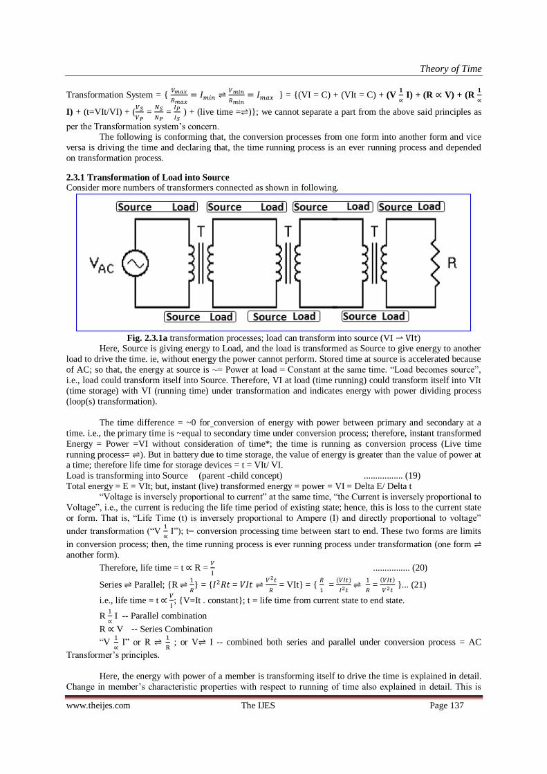
Theory of Time
www.theijes.com The IJES Page 137
Transformation System =
= (VI = C) + (VIt = C) + (V
∝ I) + (R ∝ V) + (R
∝
I) + (t=VIt/VI) + (
=
=
) + (live time = ); we cannot separate a part from the above said principles as
per the Transformation system‘s concern. The following is conforming that, the conversion processes from one form into another form and vice
versa is driving the time and declaring that, the time running process is an ever running process and depended
on transformation process.
2.3.1 Transformation of Load into Source Consider more numbers of transformers connected as shown in following.
Fig. 2.3.1a transformation processes; load can transform into source (VI t)
Here, Source is giving energy to Load, and the load is transformed as Source to give energy to another
load to drive the time. ie, without energy the power cannot perform. Stored time at source is accelerated because
of AC; so that, the energy at source is ~= Power at load = Constant at the same time. ―Load becomes source‖,
i.e., load could transform itself into Source. Therefore, VI at load (time running) could transform itself into VIt
(time storage) with VI (running time) under transformation and indicates energy with power dividing process
(loop(s) transformation).
The time difference = ~0 for conversion of energy with power between primary and secondary at a
time. i.e., the primary time is ~equal to secondary time under conversion process; therefore, instant transformed
Energy = Power =VI without consideration of time*; the time is running as conversion process (Live time
running process= ). But in battery due to time storage, the value of energy is greater than the value of power at a time; therefore life time for storage devices = t = VIt/ VI.
Load is transforming into Source (parent -child concept) ................. (19)
Total energy = E = VIt; but, instant (live) transformed energy = power = VI = Delta E/ Delta t
―Voltage is inversely proportional to current‖ at the same time, ―the Current is inversely proportional to
Voltage‖, i.e., the current is reducing the life time period of existing state; hence, this is loss to the current state
or form. That is, ―Life Time (t) is inversely proportional to Ampere (I) and directly proportional to voltage‖
under transformation (―V
∝ I‖); t= conversion processing time between start to end. These two forms are limits
in conversion process; then, the time running process is ever running process under transformation (one form
another form).
Therefore, life time = t ∝ R =
................ (20)
Series Parallel; R
= =
= VIt =
=
)
=
)
... (21)
i.e., life time = t ∝
; V=It . constant; t = life time from current state to end state.
R
∝ I -- Parallel combination
R ∝ V -- Series Combination
―V
∝ I‖ or R
; or V I -- combined both series and parallel under conversion process = AC
Transformer‘s principles.
Here, the energy with power of a member is transforming itself to drive the time is explained in detail.
Change in member‘s characteristic properties with respect to running of time also explained in detail. This is

Theory of Time
www.theijes.com The IJES Page 138
universal theory; I tried to join all principles under the system to make 100% clarification. Now we can take
decision to make 100% conformation on the considerations said above. And we can use same limits for universe
transformation system.
Reminder: Series Parallel = =
= VIt
(1) + (9) (V∝R) + (V
∝I) = V ∝
=VI/R = = C ................. (14) Recall
If we consider V ∝
, then R=VI in watts ................. (22)
Therefore, RW/RΩ =
= VI/ (V/I) = = C go to series (14)
RWRΩ = Power x Resistance = (VI) x (V/I) = = C go to parallel (15)
i.e.,
∝ = (Rw∝ I); (
∝ I) ................. (23)
RWRΩ ∝ = (Rw∝ V); (RΩ∝ V) ................. (24)
Since, RΩ
- based on (VI = C and VIt = C under conversion process (V
∝ I))
2.4 Storage devices
Above the properties of electricity under transformation was analyzed using a type of storage device
(battery) and clarified using AC Transformer. Other storage devices like Capacitor, Electro magnet, permanent
magnet, Matter (atoms) also analyzed in same manner and will be confirmed whether the principles are same.
This will help us to do deep analysis and to derive the particle structure and its properties under transformation.
2.4.1 Capacitor’s characteristic properties under Transformation process
Capacitor is another one type of time storage device. In capacitor, the ampere (number of energy with power or number of members) is stored as explained in the above derivation; i.e., resistance between the parallel
plates is designed based on the voltage rating (V∝R). As per the parallel combination‘s derivation, the ampere is
directly proportional to area.
I ∝ 1/R; I = Constant ∝ area of capacitor‘s parallel plates; C = Capacitance;
In parallel : C =Capacitance = C1+C2+…
: I = Ampere = I1+I2+...
In series : 1/C = 1/C1+1/C2+…
: V = V1+V2+...
Therefore, C ∝ 1/R = I/V Parallel combination
1/C ∝ R = V/I Series combination
C
∝ R; RC =Constant =t (compared with resistance) ................. (C0)
(21) Series Parallel =
=
)
=
)
(V= IR)
* Charge a capacitor from battery and the charged capacitor is ready to give energy to load; it is acting as load
while charging (Pt = VI*t) and acting as source (VIt) while discharging. This is explaining about transformation
of load into source.
The life time of the current form under energy with power dividing process is considered as ―t‖ years
(start to end), then 1/t years (end to start) for energy with power adding process or restoring process (time taken
for Transformation) Based on t∝ .
Capacitance conversion: making storage (energy) from series to parallel is possible; but storing of energy from
parallel to series is not possible due to low potential. (But which is possible during recycling process. i.e., for
restoring (recycling), the system should transform themselves into least values with highest number of members to generate resistance less condition among them for joining process / condensation process) i.e., they can join
together due to strength less (least energy with least power) condition of each and every members.
Two differences
only possible
Two differences
only possible
comparison Resistor Capacitor
Series
combination R=R1+R2+… 1/C = 1/C1+1/C2+…
Parallel
combination 1/R=1/R1+1/R2+… C = C1+C2+…

Theory of Time
www.theijes.com The IJES Page 139
i.e., Joining is possible because of least resistance condition among them to build themselves into one
member. - Refer 2.8.2
Start =
(Time running process = ) As per conversion
process,
Series Combination Parallel Combination
In other words, R (
)
Therefore, (
) (
) and R
∝ C
Under energy with power adding and dividing process, If we consider series combination has one
number of energy with power and parallel combination has many number of energy with power; therefore, Vt =
Potential energy per member (having time storage) with V as power per member (having live time running
process) and I = number of members under conversion process. If we consider number of members; then, we
can Neglect denominator values in start and end limits.
V I; i.e., Member Members – this is for understanding purpose (simplified).
Example: 100V/1 Member 100 Members/1volt; i.e., (Start End)
Consider Voltage = V as Value and Ampere = I as ~zero; then the limits (start end) could be
considered as ―Value Zero‖; since, the ampere with least voltage is value less =~ ZERO.
But, VI of Series = VI of Parallel Combination and VIt of Series = VIt of Parallel Combination.
)
) = minimum members (I)
)
) = maximum members (I)
A member‘s voltage is not constant; it‘s varying (reducing) with respect to running of time. Since, system
resistance is not constant under transformation (V∝R), and the time duration is more than zero for storage devices under transformation.
Capacitance is inversely proportional to Resistance. But with respect to V and I, there is no change in
characteristic properties from the previous derivation of battery. Since, the capacitor is also a storage device.
i.e., principles of Capacitor = principles of battery.
Fig. 2.4.1 Combinations of Capacitor with load under conversion process (charging and discharging)
First the capacitor is charged using S1 by closing and keeps it in open after charging; then discharging
the capacitor using S2 by closing. (Used high value resistors to get clear measurement) The charged load
(capacitor) is transforming as source to give energy to resistors to store particles as energy with power rays =
light or heat rays. V, I and time taken for discharging measured. The power is measured at constant ampere
condition by using variable resistor because of the capacitor‘s constant area condition. The derivation of
Capacitor is also same like battery. But this gives some additional clarification. i.e., we could consider capacitor
as battery and can store energy (voltages) between the Parallel plates with proper gap or resistance and too long
length wire is not required to separate the polarities. Its mean, we can consider series energies as one number of
energy, and the resistance is important to separate the polarities (resisting mixing together).

Theory of Time
www.theijes.com The IJES Page 140
Fig. 2.4.1b Trace for members consideration in Existing science / theories [8]
The ampere is stored in capacitor(C
∝ R). As per the above derivation (energy adding and dividing
process = energy conversion process) each electric field lines could be considered as value of energy (energy of
each Field lines ∝=Voltage), and number of electric field line could be considered as number of energy∝=
Ampere.
i.e., Voltage x time = Potential Energy per member;
Voltage indicates the value of energy; without voltage, the ampere is useless or valueless.
If we consider capacitor = battery (storage Device) then, E = ½ VIt; (based on E= ½ m )
= ½VI; t= RC; for storage devices
Therefore,
=
(
)
=
t =
(
)=½ R = ~½VI (each individual‘s value) ....………. C1
Energy of Capacitor (E) = ½ C - from Wikipedia [9]
= ½ C = ½
= ½ VIt ……………. C2
Other words, E = ½ C =
t =
t =
t = ½ VIt ……………. C3
Battery principles = Capacitor principles; therefore, E = ~½ VIt (each individual‘s value).
Each individual‘s value is E = ~½ VIt and P=
= ½VI under transformation.
VI =C and it is available even the time is less than a second under transformation system. VI=C and VIt =C forever under transformation system (total value). Therefore, t= VIt/ VI
In transformation system (total), VI = Ever constant and VIt= Ever constant under transformation
process from series to parallel and parallel to series. (We cannot consider energy per second for power, because
VI = C even the time is less than a second under transformation. hence the time is running for ever as
conversion process ( ). (i.e., <<<Infinite Past <=Present=> Infinite Future>>>; and the past cannot/ could not
be return; but, the similar past will be come in future as future after (re)cycling process to run the time because
of transformation process. i.e., Series Parallel.
t= )
) ; time running is ever running process under conversion process ( ).
We could not stop the time running process or energy conversion process; but we can accelerate / decelerate the time running speed by accelerating / decelerate the energy consumption rate (transformation rate).
Therefore, the time is running without start at the same time without stop or ―Start Stop‖ in transformation
system, (i.e., the system is having start and end under transformation ( ). i.e., both positive and negative answer
is meeting with the system‘s principles.)
Vt is Potential energy with V is potential power per member (I).
No. of Members
considered
No. of Members
considered
(For Reference only) (For Reference only)

Theory of Time
www.theijes.com The IJES Page 141
I is number of members available inside the system.
R is resistance to break or separate or explode (electricity resistance to transformation) a big energy
with power of one member into so many members of small energy with power. (This is possible under source with Load condition = Closed circuit; i.e., the stored (hidden) time in source (stored time) is running (showing)
through power under ‗time Storage time running‘ condition.
t is life time of energy under time running process w.r.t conversion process ( ) speed
Ampere ∝ or = to number of energy with power.
Discharging characteristics properties measured based on Constant Current Condition. Reason, the
capacitor‘s area is constant during discharging. We have to reduce the resistance value while discharging with
respect to reduction in voltage as per the condition of V∝R, to make constant current condition.
Table 2.4.1a Capacitor‘s Energy calculation under time running @ constant ampere condition
Without ~voltage the ampere is value less; the voltage is playing major role in electricity to show the value of energetic. We could see that, the stored energy value of current form is reducing gradually due to running of
time because of closed circuit, and reduced energy instantly converted into power, i.e., each and every member
is being converting its energy into power through resistance (conversion of energy with power from one form
into another form) to drive time. No resistance mean no life time. (i.e., t∝R; and Resistance /member is more
than the total system‘s resistance). Normally for storage devices, Total E = ~ ½ VIt (running of time is available
more) = ½ C (running of time is just a second (derived in current theories) or ~no running of time). i.e., C=E.
Fig. 2.4.1c Capacitor‘s Energy calculation without running of time as per current theory (t=1s)
If any changes in voltage, then only we could see the changes in E/C ratio. Therefore, V=Constant
(same value in all members inside the system) at a time among them within the system; then E ∝ C; E/C=Constant when V=constant among them. Power =½VI in Watts and Energy = ½ VIt in Joules for storage
devices. But, in total transformation system (parents + children) E= VIt and P= VI are constant forever under .
Total transformation system consist base or parent loop + converted loops (child loops).
Electricity Field lines = electric spark (arc) lines between parallel plates (for capacitor): Each and every
electric field line indicates that, the value of voltage or potential power; and number of field lines indicates that,
the value of ampere; I have considered based on the above derivation. We could see Number of Electric field
lines or number of electric sparks lines in existing theories and which is verified practically. Therefore, electric
field lines or electric sparks lines are satisfied with the above said derivation (indicates members consideration
inside the system). Without energy, the power cannot perform. The power is result of regulated (reduced)
utilization of source energy at load to drive the time through transformation. Example: battery energy = source and energy consumption by load resistor = power. But, value of energy > value power at a time; i.e., Energy
(stored time) is transforming into Power x time (running or exploding time).
unit
time (t) ---> 0 1 2 3 4 5 6 7 8 9 10 second
Voltage (V) 10 9 8 7 6 5 4 3 2 1 0 Volt
Ampere (I) 0.12 0.12 0.12 0.12 0.12 0.12 0.12 0.12 0.12 0.12 0.12 A
Resistance (R) 83.3 75 66.7 58.3 50 41.7 33.3 25 16.7 8.33 0 Ω
VI(max) (P) 1.2 1.08 0.96 0.84 0.72 0.6 0.48 0.36 0.24 0.12 0 W
VI (avg) (P) 1.14 1.02 0.9 0.78 0.66 0.54 0.42 0.25 0.15 0.05 0 W
Total Energy ('E) 5.89 J the time is running evenly
Total time (t) 10 s E=~0.5VIt = 6.00 J
Average energy /s (P) 0.59 W
Capacitor discharging under constant current condition
1 2 3 4 5 1 2 3 4 4
C 156 500000 90000 8000 15 µf C 100 10045986 100 78600 78600 µf
C 0.00 0.50 0.09 0.01 0.00 F C 0.00 10.05 0.00 0.08 0.08 F
V 12 12 12 12 12 volt V 20 20 20 41 42 volt
E 0.01 36.00 6.48 0.58 0.00 (J/s)*s E 0.02 2009.20 0.02 66.06 69.33 Ws
E/C 72 72 72 72 72 constant E/C 200 200 200 840.5 882 J/F
Capacitor's Energy Calculation
Time duration is just a second

Theory of Time
www.theijes.com The IJES Page 142
; ;
Fig. 2.4.1d Electric Spark lines = Electric Flux lines = Number of members = ampere (I) [10]
Here, I have reduced the difference as much as possible to bring everything under one for better
understanding (Value of each spark line is considered as voltage and number of spark lines are considered as
ampere). Proof: Fig 2.2c.
Another proof: if we do reducing or increasing the gap between positive and negative terminal in a high
voltage DC power supply, the number of spark lines increased while reducing the gap and the number of spark
lines reduced while increasing the gap between positive and negative terminal. i.e., I
∝ V; Hence, this action is
meeting with the above said derivation. Therefore, number of field lines = number of arc lines = number of
voltages = ampere or (=∝total ampere / ampere of an arc line or one member)
Note: I did not use or consider electron or number of Electron for analyzing characteristic properties of
Electricity under conversion process; reason I have considered ampere as number of members (loops = closed
circuits) or individuals and which is not having constant value under conversion process. The value of a member
(time storage with running time is indicates energy with power = Storage with load) is undergoing energy with
power dividing process and adding process under conversion process. Then the members are increasing and
dividing the energy with power gradually during energy with power dividing process; finally the least value of
many most… members could be converted themselves into one member during energy with power adding
process within the system. Therefore, we cannot consider electron value as constant value or number of electron
here.
Logic: without consideration of Electron or number of electron, the electricity conversion process and its
characteristic properties are defined /derived systematically. If we introduce electron or number of electron, then
there is no definition related with energy with power adding or dividing process on electron in existing theories.
A member‘s energy and power are not constant within the system with respect to running of time
(transformation process). Therefore we cannot consider electron as member. (We will discuss later about
electron…)
2.4.2 Magnet and its magnetism under transformation
Magnet with flux lines are indicates that, the energy with power structure (loop structure). Same poles
repel each other and different poles attract each other. Series and parallel combination of magnet is as shown in
the following diagram under conversion condition.
=
Fig. 2.4.2a Series and Parallel combination of Magnet with members consideration
Logic: Loop transformation; 8 no. of Flux line 4 no. of Flux line (for understanding only)
Magnetic Energy with power of series is equal to parallel as shown in the above said conversion process. The difference between series & parallel combination is compared as given below.

Theory of Time
www.theijes.com The IJES Page 143
Table 2.4.2a Difference between series and parallel combination of magnets under transformation
Number of flux lines doubled in parallel combination due to repel action and Number of flux lines are same in
series combination due to attraction. Hence Energy addition with power addition is takes place in series
combination. But in parallel combination, there is no energy or Power addition takes place due to repel.
Logic: Magnetic Flux lines in Loop condition are indicates Closed Circuit or loops. We could not make open circuit using magnetic energy with power loops circuit. Stored time in source is running through the power at
flux lines. i.e., Magnetic energy and power are reducing gradually over a period of time; hence energy with
power dividing process is driving the time. If we open the loop, then we can stop the time running
transformation process… try…
; Fig. 2.4.2b Magnet and its flux lines [11] in loops structure; electric loops structure (members) [10]
Magnetic loop structure indicates energy with power structure; the time is in stored condition at source
(energy) and the time is in running condition at load. We must consider always closed circuit for any circuit; in
open circuit, we could/ must consider big (certain) resistance value based on loss due to time. That is, the time is
running very slowly due to big resistance in open circuits. Therefore the time is running so ever under
transformation process from series to parallel and parallel to series. Resistance between open circuits can be calculated based on loss due to time.
We could take decision with clarification based on comparison between electric energy with power and
magnetism (magnetic energy with power). This is an additional proof for the above said derivation. Hence,
magnet with flux lines are satisfied with the above said derivation. The circuit must be in closed condition to run
the time by using stored time.
Electro-magnetism = Electricity = ―Electric Energy with Power +Magnetic energy with power‖
Electricity under conversion process is analyzed based on Energy with power transformation principles
under Law of Conservation of Energy with Power as said in above. In electric closed circuit, the magnetic
energy with power (loop) is generated over the electric flow; magnetic and electric energy with power are
relative components of electricity system.
Fig. 2.4.2c Electromagnetic structure (Closed Loops): From Current theories & Correction [11]
Sl. No. Series Combination Parallel Combination
1 No. of Flux lines = ½ of total number of Flux lines
2 Length of Magnet = 2 times of Length
3 Magnetic Power = Equal Power
4 Area of Magnet = ½ of Area
5 Magnetic Energy = Equal Energy
6 Attraction process Repel process
S
SECTIONAL VIEW
-
+
+
---
N
S
SECTIONAL VIEW
-
+
+
---
N
Load Load

Theory of Time
www.theijes.com The IJES Page 144
Under energy with power conversion process ( ), there is no constant exist in Electricity characteristic
properties (V, I and R). Therefore, the energy with power system is being transforming itself because of closed
circuit. ―Wherever electric potential energy (Storage) with power (load) is there, there should have magnetism because of closed circuit‖ (here considered ―electricity‖ = ―Electro Magnetism‖ = ―value of Electric energy with
power = value of Magnetism‖), -considered based on conversion process (refer 2.5). i.e., closed circuit is leads
to time running process in the form of energy with power dividing process, - based on the above said derivation.
Due to closed circuit we cannot separate either electric energy with power and magnetism. Both are mingled/
interlocked as system of Electricity. Therefore, electro-magnetism = Electricity = ―Electric Energy with Power
(closed circuit) combined Magnetism (closed loops are one in another as shown in the following)‖. [12]
The followings are the direction of polarities in electro-magnetism or system of Electricity in 2D and 3D
View. This is interpreted (modified to relate each other) from the normal electric circuit to relate each other and
with ~Newton‘s 3rd law. Any circuit* can meet with this structure. Here, direction of polarities (+, - , S and N)
are shown with arrow. – verified
Fig.2.4.2d 2D Electricity Loops or Electro-Magnetic Loops (unique) with polarity directions
The above said 2D graphical interpretation of electro-magnetic system is converted into 3D isometric
view as shown in following.
Fig. 2.4.2e 3D Electricity Loop(s) or Electro-Magnetic Loop(s) and it‘s Direction of Polarities
Both magnetic loop(s) and electric loop(s) are inter-linked as one in another as shown in the above diagram and
any circuit can meet with this structure. Arrow is showing the direction of polarities.
2.5 Analysis on Maximum and Minimum Power condition for checking the Limits (V, I, R)
Maximum and minimum power conditions compared to cross check the limits, which was set in
Energy with power adding and dividing derivation; this will help us to verify and to confirm the limits within
the electricity under transformation condition. Finally this will be used to take prompt decision on structure of
system and its range between the forms under transformation (i.e., start end or Value ~Zero or Series
Parallel or Member Members).
The following is a comparison statement between Closed (short circuit) and Open circuit (as per
current theories) to determine the range and limits between the forms (series and parallel forms).
While short circuiting, electric potential value is disappearing and magnetic potential value is
appearing. Similarly (Relatively) in open circuit, the magnetic potential value is disappeared and appearing
electric potential value. That is both values are inversely proportional under transformation like series, parallel

Theory of Time
www.theijes.com The IJES Page 145
circuits under transformation. Energy and power are same between the electric and magnetic potential
transformation systems.
Fig. 2.5a Analysis on Maximum and Minimum power condition - verified
Value of Electric energy with Power = Value of Magnetic energy with Power; the characteristic
properties of maximum and minimum power condition is determined below based on the above said diagram
under transformation condition. i.e.,
=IHighest
= ILeast electricity limits determined based on
above diagram and this is meeting with the above said derivation.
Therefore, Total Electric Energy = Total Magnetic Energy = ~½VIt and Total Electric Power = Total Magnetic
Power = ~½VI. (While short circuiting, electric source Voltage is disappeared and magnetism appeared)
i.e., value of Magnetic potential is inversely proportional to value of electric potential under transformation. i.e.,
―Where ever energy is there, there should have power under energy with power conversion process to run the
time running process due to closed circuit. ( = time)‖
Explanation: ―In a energy with power circuit, If Electric potential (voltage =∝ potential) value is appeared as
maximum as possible, then the magnetic potential value can be appeared as minimum as possible (V
∝ I);
likewise, if Magnetic potential value is appeared as maximum as possible, then the Electric potential value
(voltage =∝ potential energy) can be appeared as minimum as possible.‖(or) Other words ―In a circuit, If
Electric potential value (voltage) is appeared in 100%, then the magnetic potential value cannot be appeared;
Likewise if Magnetic potential value is appeared in 100%, then the Electric potential value cannot be appeared
(V
∝ I).‖
Logic: Here also 2 differences only possible, one is short-circuit and another one is Open-circuit.
Any circuit can come under this range. In this range, one end talking about magnetic circuit (highest ampere)
and other end talking about electric circuit (highest voltage). But, both are coming under electricity or electro-
magnetism. Refer - 2.7 (one loop should have potential time storage and other loops should ~not have potential
time storage at a time)
2.6 Energy with power transformation process structure design (3D Formulation)
AC Transformer is energy with power converting device in live transformation processing condition, this
analysis is to know why/ how it‘s transforming? - Through transformation structure design in 3D and deep
analysis.
The following is analysis on energy with power conversion process from one from into another form (transformation) through AC transformer to determine logics. As per the above said energy with power
transformation derivation, the logics can be derived from the combination principles of (Energy = VIt=
Constant) + (Power = VI=Constant) +V
∝ I). i.e., energy with Power transformation process.
The following is AC Transformer‘s primary and secondary values (V, I and R) measured in various levels and
the graph is drafted.

Theory of Time
www.theijes.com The IJES Page 146
Fig. 2.6a Characteristic Properties of Power Transformer (VI=C) in 2D graph
The following is 3D electricity structure designed using the above said 2D electricity power graph for
better understanding by using the logics of ―Ampere ∝=number of members ∝ Area‖ + ―Resistance ∝ Length
and Voltage ∝ Resistance‖.
Fig. 2.6b Characteristic properties of Power Transformer (VI=C) 3D Graph
This is Electricity power building structure in 3D form like normal building structure. We can increase
the potential (Voltage per member) by reducing ampere under transformation (in loop structure), therefore the
―Voltage must be directly proportional to resistance‖. The voltage, resistance is gradually reducing and increasing ampere during energy dividing process. A member of energy with power is divided during time
running process as shown in above. In energy adding process, all small members added into one. The following
is an equivalent mechanical power (Potential Energy deformation) building structure designed based on the
above electricity building structure for doing deep analysis. Refer mountain deformation due to gravity for
further clarification. (For gravity refer Fig. 2.8.2h: divided low value particles leaving from heavy masses,
which creates gravity toward center of mass.)
Fig. 2.6c equivalent mechanical change in Energy (
=power) [5] building structure designed based on
electricity transformation (AC Transformer‘s principles)
Interpretation w.r.t Mechanical
PE= mgh (considered t=1 sec) 𝑬
𝐭= Power (P) =>energy conversion
t= Total PE/ Power = life time
Interpretation w.r.t Mechanical
PE= mgh (considered t=1 sec) 𝑬
𝐭= Power (P) =>energy conversion
t= Total PE/ Power = life time
Interpretation w.r.t Electricity
PE= VIt (time considered)
Power (P) = VI (time not considered) i.e., P=C, even the time is less than a
second.
t= Total PE/ Power = time (Live
time can be considered for power)
Interpretation w.r.t Electricity
PE= VIt (time considered)
Power (P) = VI (time not considered) i.e., P=C, even the time is less than a
second.
t= Total PE/ Power = time (Live
time can be considered for power)

Theory of Time
www.theijes.com The IJES Page 147
F1 = 1883.5 = 2F2 = 3F3 = 4F4; considered g=9.81 m/ Consider a big potential member is transforming into 2 or more than 2 small potential members under
energy dividing process due to gravity; and considered Power is constant under transformation. Then, sum of
each member‘s Energy + Work done is constant under transformation. i.e., Energy = E= sum of each Members
Energy + Work done = C and Power =
= C under transformation.
Fig. 2.6d Mechanical Change in
building structure derived from Energy building Structure under
transformation due to gravity (importance of members; E=C and P=C)
A member of high potential energy under transformation is shown in the above diagram. Top mass of the energy level is transforming into next level during time running process due to gravity. Area (number of
members) is increasing during energy dividing process. Time running (Energy dividing process is a type of
energy with power transformation process) process from series to parallel is resulting work done.
Table 2.6a A member‘s Deformation structure calculation based on above - Mechanical
Transformation properties are calculated and found that, the Energy is directly proportional to Pressure.
And power is directly proportional to ‗change in pressure/ change in time‘. And meeting with series, parallel and
transformer‘s principles as said above.
Model Calculation for Power (E4 transformation):
A =Area=24 m2 ; H= Height=1m
ρ =density= 2 kg/m3 ; g= 9.81 m/s2
ΔV = change in Volume =AH = 24*1 = 24m3 ; Δm= Δmass = ρ(ΔV) = 24*2= 48 kg
h=h‘-h‘‘ = potential energy transformation head = 3.5- 1.5 = 2m; ∂t= 1s
P=Power =∂E/∂t = ∂(mgh)/∂t = 48*9.81*2/1 = 941.76 J/s
ΔF= transformed Force =(Δm)g =48*9.81 =470.88 N
Δp=ΔF/A=470.88/24 =19.62 N/m2; h=ΔE/ΔF= 941.76 /470.88 = 2m
ΔE/Δt.A = 941.76 /24 =39.24 ∝ F/A = 1883.52/24 = 78.48 N/m2
No. of Members = ∆A = A/a = a/a =24/24 =1 number
Conclusion: ―Δp/Δt is directly proportional to Power‖ based on ―Energy is directly proportional to Pressure‖
(refer impacting (collision) of even masses for further clarification); force is required to do transformation.
Energy and Power comparison within Energy Transformation Structure (a member's deformation Structure)∆E h ∆ph Member∆E ∆t Total E=C
A H V=AH ∆m h= h'-h'' g ∆E/∆t=(∆m)gh) ∆F=(∆m)g ∆p=∆F/A ∆E/∆t*∆t ∆E/∆F ∆E/A ∆A=A/a (∆p)Ah ∆E/(∆E/∆t) ∑P+Esource
24 1 24 48 2 9.81 941.76 470.88 19.62 941.76 2 39.24 1.0 941.76 1 3767.04
32 1 32 64 1.5 9.81 941.76 627.84 19.62 941.76 1.5 29.43 1.3 941.76 1 3767.04
48 1 48 96 1 9.81 941.76 941.76 19.62 941.76 1 19.62 2.0 941.76 1 3767.04
96 1 96 192 0.5 9.81 941.76 1883.52 19.62 941.76 0.5 9.81 4.0 941.76 1 3767.04
Total Energy = E =∆E1+∆E2+∆E3+… P∝F E∝p h ph Member E ∆ life t E∝Ft deformation
A H V=AH m h= h'-h'' g E=mgh F=mg p=F/A E/F E/A A/a 0.5 pV E/0.5pV t=E/P Ft E/Member
24 4 96 192 2 9.81 3767.04 1883.52 78.48 2 157 1.0 3767.0 1 4 7534.1 3767.04
32 3 96 192 1.5 9.81 2825.28 1883.52 58.86 1.5 88.29 1.3 2825.3 1 3 5650.6 2118.96
48 2 96 192 1 9.81 1883.52 1883.52 39.24 1 39.24 2.0 1883.5 1 2 3767.0 941.76
96 1 96 192 0.5 9.81 941.76 1883.52 19.62 0.5 9.81 4.0 941.8 1 1 1883.5 235.44
∆=delta ; E is directly proportional to p; ie, E is directly proportional to F and inversely proportional to A; H = Height; h=head ; p=pressure,
PE is transforming into KE; then PE is inversely proportional to KE under gravity A,a=Area, P=Power; ET =P*t = Esource + P*t; ∑P = Pt
Power= ∂E/∂t = Change in Energy/Change in time (=1unit)

Theory of Time
www.theijes.com The IJES Page 148
Model Calculation: for Energy
A=Area=24 m2 H=Height=4m ρ=density= 2 kg/m3 g=9.81 m/s2 h=head = 2m
V=Volume =AH = 24*4 = 96m3 m=mass =ρV = 96*2 = 192kg
E=Energy =mgh = 192*9.81*2 = 3767.04 J
F=Force =mg =192*9.81 =1883.52N
p=F/A =1883.52/24 =78.48 N/m2
h=E/F =3767.04/1883.52 = 2m
ph =78.48*2 =157 = E/A = 3767.04/24 = 157 J/m2
Conclusion: Energy is directly proportional to Pressure
Energy and pressure are having direct relation, and indicates stored time. Power and change in pressure / change in time are having direct relation and indicates running time.
Based on energy level the system‘s interpretation is varying and considered the system‘s change in
energy due to change in time (power) is constant under transformation. The Energy and power both must be
available in the system to run the time. Therefore, we can bring mechanical energy‘s system under energy with
power transformation condition as said above.
In electricity, we can consider force due to attraction / repletion. Here, the electricity potential energy
with power transformation principles again clarified using mechanical pictorial representation. i.e., R∝V and I
∝
R under energy with power transformation.
Where ever energy is there, there should have power for transformation to drive the time; no
transformation system will exist if we remove force in the above said derived system; force is essential to do
transformation and the following analysis is to know the relations and importance of Force in the transformation
system.
The power is constant within the system under transformation in each and every energy level. And
Force/area = p ∝ Energy = E or Force x time =J ∝ Transformed Energy =ETrans and (
) ∝ (
)
or Force =F=mg ∝ Power =P=
both are relative components in the system of nature under transformation
process, therefore ―wherever force is there, there should have energy transformation process (power) (time
running process)‖.
Resistance is indication of life time of the energy.
∝ …… (20) (R=V/I)
∝ I …… (20a)
t ∝ V …… (20b) (t = life time)
(20a) + (9) = VIt = Constant
(20b) + (9) = VI/t = Constant under transformation
All the relative equations are derived from the base equations of ―Resistance is directly proportional to Voltage
and inversely proportional to ampere‖
If we consider = live time running process; then, VIt of Source / VI of Load = life time = t. If we
consider ampere (I) as number of energies then the structure must be like shown in following. And we have to
link this with Newton‘s 3rd Law to relate with transformation.
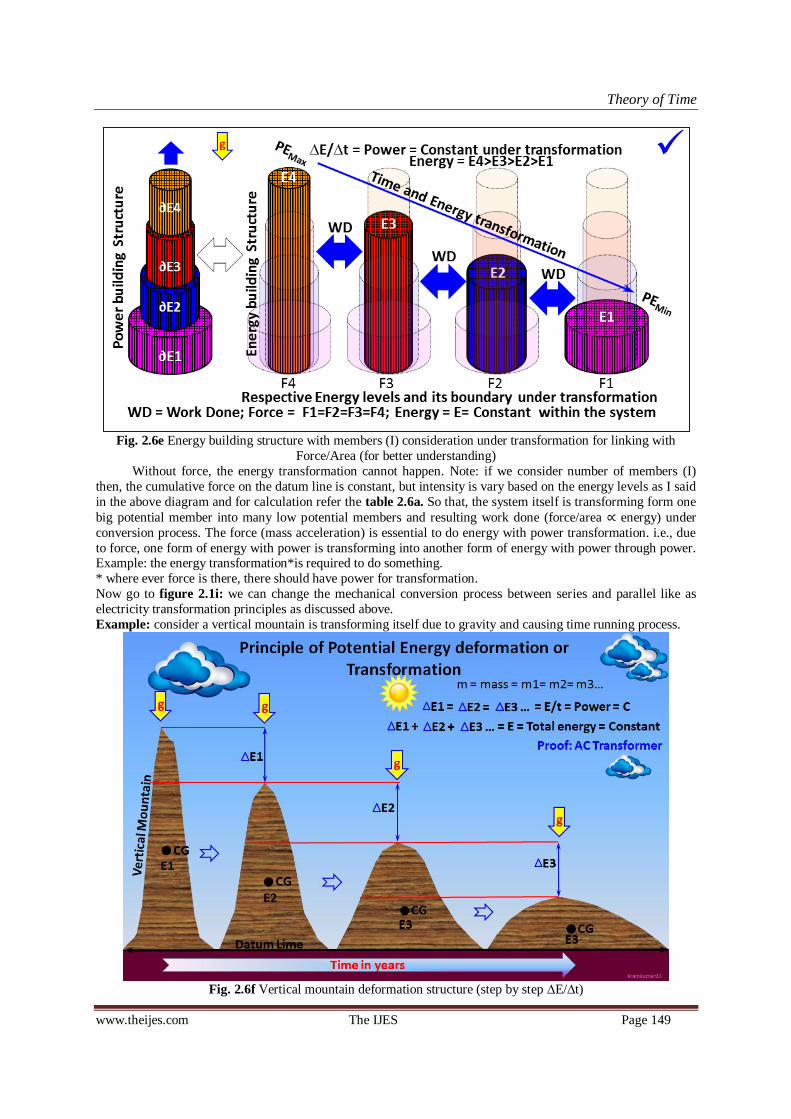
Theory of Time
www.theijes.com The IJES Page 149
Fig. 2.6e Energy building structure with members (I) consideration under transformation for linking with
Force/Area (for better understanding)
Without force, the energy transformation cannot happen. Note: if we consider number of members (I)
then, the cumulative force on the datum line is constant, but intensity is vary based on the energy levels as I said
in the above diagram and for calculation refer the table 2.6a. So that, the system itself is transforming form one
big potential member into many low potential members and resulting work done (force/area ∝ energy) under
conversion process. The force (mass acceleration) is essential to do energy with power transformation. i.e., due
to force, one form of energy with power is transforming into another form of energy with power through power. Example: the energy transformation*is required to do something.
* where ever force is there, there should have power for transformation.
Now go to figure 2.1i: we can change the mechanical conversion process between series and parallel like as
electricity transformation principles as discussed above.
Example: consider a vertical mountain is transforming itself due to gravity and causing time running process.
Fig. 2.6f Vertical mountain deformation structure (step by step ∆E/∆t)

Theory of Time
www.theijes.com The IJES Page 150
Here, I have considered AC transformer‘s principles to derive equivalent mechanical principles. As per
the above table, we can use same electricity principles for analyzing mechanical energy with power
transformation. i.e., ½VIt = mgh; ∆mgh due to ∆t = Power = VI (PE is transforming into KE due to time running process, since gravity force is playing major role.) The following is ‗change in Energy/ change in time‘
combined ‗change in Force/Area‘ is shown for better understanding. Transformation (via power) process with
respect to running of time is as shown in following pictorial representation. - analyzed using Algodoo.
Fig. 2.6g E/ t ∝ t relative transformation structure under Newton‘s 3rd Law (in gravity place)
Like, high head water (higher potential) low head water (lower potential) +KE or Work Done;
Top mass is deforming into next level, the power is constant in all levels like AC Transformer
(Designed based on transformer). Total Force of Each level is constant and balanced with Newton‘s 3rd Law.
i.e., Force/area and Energy both are having direct relation in transformation system. Δp/Δt and power are having
direct relation under transformation.
2.6.1 Explanation of Time storage and Time running process using water Energy cycle
Energy (time storage) and power (live or running time) both are essential to drive the time. Here, the
system of energy with power under transformation is explained below to understand the importance of time and
its natural properties.
Fig. 2.6.1a Water energy cycling process under conversion (as per time running & storing)

Theory of Time
www.theijes.com The IJES Page 151
Above diagram designed based on electricity transformation principles. We could understand that, the
Force is essential to do transformation (power). Energy – Pressure and power- ‗change in pressure/ change in
time‘ are having relational characteristic properties under transformation process. Therefore we can use Newton‘s 3rd law for analyzing Energy building structures under transformation (+F = -F); one is opposite to
another (concurrent).
If we consider both positive and negative polarity in electricity then the structure must be like ―One is opposite
to another‖ as per Newton‘s 3rd law. To confirm that, energy with power transformation is analyzed using
Newton‘s 3rd law of force. This will help us to understand relation between force and power.
Following is analysis using Newton‘s 3rd Law on energy with power transformation system to relate
Energy – Pressure and Force – Power.
Fig. 2.6.1b Power (energy transformation) - Force direct relation analysis using Newton‘s 3rd Law
Force: Action= -F = Reaction = +F
Change in Momentum: - p = + p
Force (F) is directly proportional or = to change in momentum ( p) P/m = Power/mass: -Active Power/ (m-m‘)/s = + Reactive Power/ ṁ
m-m‘/s = mass of balloon - reduction in mass of balloon/s
Force, change in momentum and power are having direct relational properties.
But -
= +
is not proportional to Force -F = + F for uneven masses… refer table 2.6.4b. But,
force is required to do transformation. Without force the transformation cannot happen. And in even masses
(m1=m2) the Force (+F = -F) is directly proportional to Power (+P = -P)… refer table 2.6.4a.
Transformed Energy = ∑
or ½
*t and Force is reason for energy transformation.
ER = Resistive Energy = energy loss due to friction / air resistance / resistance due to gravity
Epr = Pressure Energy = ~½ pV
KE = Kinetic Energy = ½ m Energy transformation from pressure energy to kinetic energy for balloon =
E = ~½pV ~(½ ṁ )t= ~(½P)t = ~½ m = ∑∆E/∆t
If m1=m2, then Power is directly proportional to Force. Ref. Fig 2.6.4a, b for further clarification.
Therefore, Force and Power are having relational properties if the opposite masses value are same; i.e., Power is
directly proportional to Force. If not same, P1/m2 = P2/m1, Hence, we can /could use Newton‘s 3rd law for
analyzing energy under transformation system.
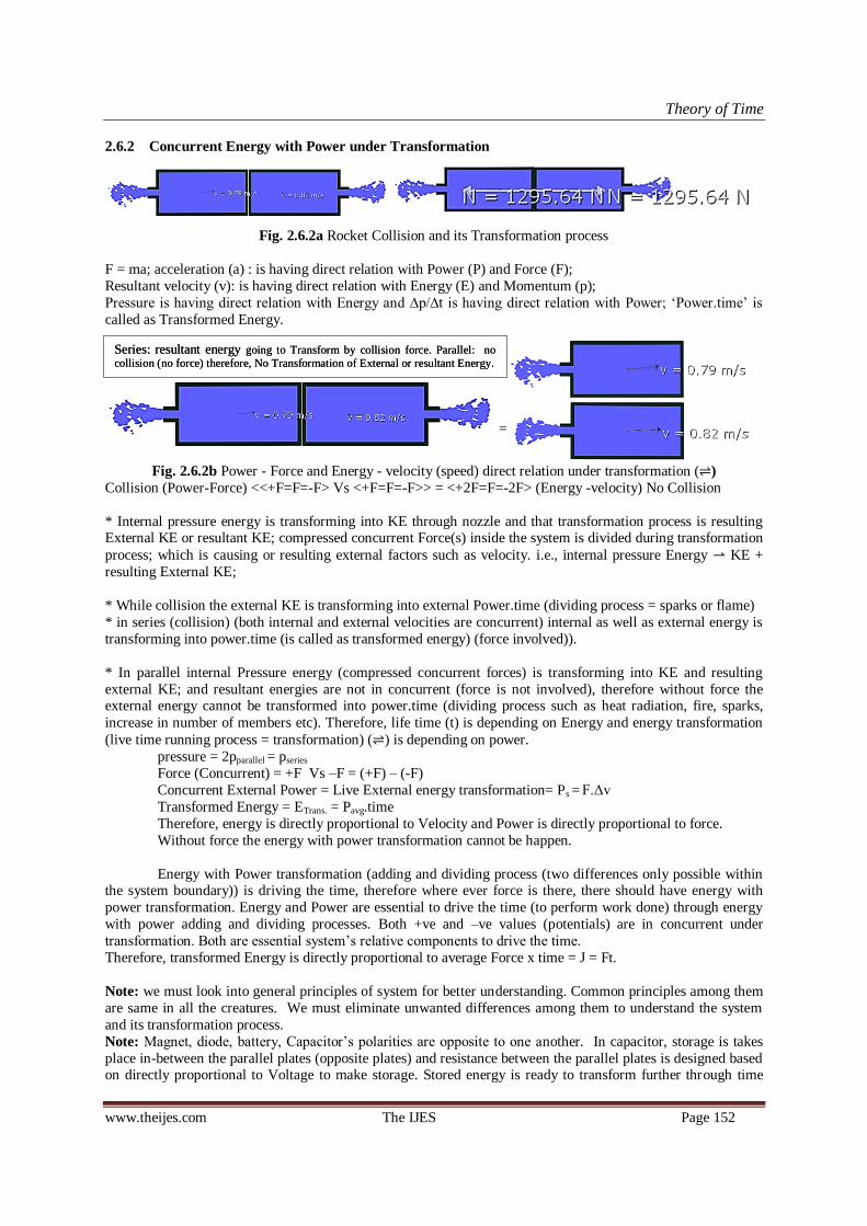
Theory of Time
www.theijes.com The IJES Page 152
2.6.2 Concurrent Energy with Power under Transformation
Fig. 2.6.2a Rocket Collision and its Transformation process
F = ma; acceleration (a) : is having direct relation with Power (P) and Force (F);
Resultant velocity (v): is having direct relation with Energy (E) and Momentum (p);
Pressure is having direct relation with Energy and ∆p/∆t is having direct relation with Power; ‗Power.time‘ is
called as Transformed Energy.
=
Fig. 2.6.2b Power - Force and Energy - velocity (speed) direct relation under transformation ( )
Collision (Power-Force) <<+F=F=-F> Vs <+F=F=-F>> = <+2F=F=-2F> (Energy -velocity) No Collision
* Internal pressure energy is transforming into KE through nozzle and that transformation process is resulting External KE or resultant KE; compressed concurrent Force(s) inside the system is divided during transformation
process; which is causing or resulting external factors such as velocity. i.e., internal pressure Energy KE +
resulting External KE;
* While collision the external KE is transforming into external Power.time (dividing process = sparks or flame)
* in series (collision) (both internal and external velocities are concurrent) internal as well as external energy is
transforming into power.time (is called as transformed energy) (force involved)).
* In parallel internal Pressure energy (compressed concurrent forces) is transforming into KE and resulting
external KE; and resultant energies are not in concurrent (force is not involved), therefore without force the external energy cannot be transformed into power.time (dividing process such as heat radiation, fire, sparks,
increase in number of members etc). Therefore, life time (t) is depending on Energy and energy transformation
(live time running process = transformation) ( ) is depending on power.
pressure = 2pparallel = pseries
Force (Concurrent) = +F Vs –F = (+F) – (-F)
Concurrent External Power = Live External energy transformation= Ps = F.Δv
Transformed Energy = ETrans. = Pavg.time
Therefore, energy is directly proportional to Velocity and Power is directly proportional to force.
Without force the energy with power transformation cannot be happen.
Energy with Power transformation (adding and dividing process (two differences only possible within the system boundary)) is driving the time, therefore where ever force is there, there should have energy with
power transformation. Energy and Power are essential to drive the time (to perform work done) through energy
with power adding and dividing processes. Both +ve and –ve values (potentials) are in concurrent under
transformation. Both are essential system‘s relative components to drive the time.
Therefore, transformed Energy is directly proportional to average Force x time = J = Ft.
Note: we must look into general principles of system for better understanding. Common principles among them
are same in all the creatures. We must eliminate unwanted differences among them to understand the system
and its transformation process.
Note: Magnet, diode, battery, Capacitor‘s polarities are opposite to one another. In capacitor, storage is takes
place in-between the parallel plates (opposite plates) and resistance between the parallel plates is designed based on directly proportional to Voltage to make storage. Stored energy is ready to transform further through time
Series: resultant energy going to Transform by collision force. Parallel: no
collision (no force) therefore, No Transformation of External or resultant Energy. Series: resultant energy going to Transform by collision force. Parallel: no
collision (no force) therefore, No Transformation of External or resultant Energy.
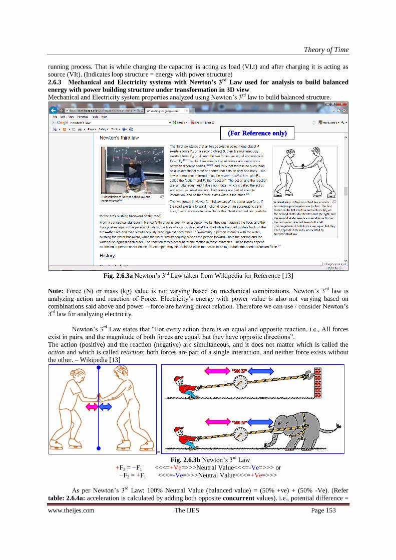
Theory of Time
www.theijes.com The IJES Page 153
running process. That is while charging the capacitor is acting as load (VI.t) and after charging it is acting as
source (VIt). (Indicates loop structure = energy with power structure)
2.6.3 Mechanical and Electricity systems with Newton’s 3rd
Law used for analysis to build balanced
energy with power building structure under transformation in 3D view
Mechanical and Electricity system properties analyzed using Newton‘s 3rd law to build balanced structure.
Fig. 2.6.3a Newton‘s 3rd Law taken from Wikipedia for Reference [13]
Note: Force (N) or mass (kg) value is not varying based on mechanical combinations. Newton‘s 3rd law is
analyzing action and reaction of Force. Electricity‘s energy with power value is also not varying based on
combinations said above and power – force are having direct relation. Therefore we can use / consider Newton‘s
3rd law for analyzing electricity.
Newton‘s 3rd Law states that ―For every action there is an equal and opposite reaction. i.e., All forces
exist in pairs, and the magnitude of both forces are equal, but they have opposite directions‖.
The action (positive) and the reaction (negative) are simultaneous, and it does not matter which is called the
action and which is called reaction; both forces are part of a single interaction, and neither force exists without
the other. – Wikipedia [13]
=
Fig. 2.6.3b Newton‘s 3rd Law
+F2 = −F1 <<<=+Ve=>>>Neutral Value<<<=-Ve=>>> or
−F2 = +F1 <<<=-Ve=>>>Neutral Value<<<=+Ve=>>>
As per Newton‘s 3rd Law: 100% Neutral Value (balanced value) = (50% +ve) + (50% -Ve). (Refer
table: 2.6.4a: acceleration is calculated by adding both opposite concurrent values). i.e., potential difference =
(For Reference only) (For Reference only)
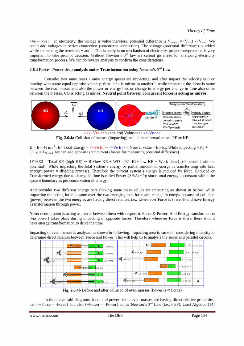
Theory of Time
www.theijes.com The IJES Page 154
+ve – (-ve). In electricity, the voltage is value therefore, potential difference is Vneutral = (V+ve) - (V-ve). We
could add voltages in series connection (concurrent connection). The voltage (potential difference) is added
while connecting the terminals + and -. This is analysis on mechanism of electricity, proper interpretation is very important to take prompt decision. Without Newton‘s 3rd law we cannot go ahead for analyzing electricity
transformation process. We can do reverse analysis to confirm the considerations.
2.6.4 Force - Power deep analysis under Transformation using Newton’s 3rd
Law
Consider two same mass - same energy spears are impacting, and after impact the velocity is 0 or
moving with some equal opposite velocity; then ―one is mirror to another‖; while impacting the force is same
between the two masses and also the power or energy loss or change in energy per change in time also same
between the masses. CG is acting as mirror. Neutral point between concurrent forces is acting as mirror.
<<<+Ve>>><<<neutral Value>>><<<-Ve>>>
Fig. 2.6.4a Collision of masses (impacting) and its transformation and PE KE
E1= E2= ½ m ; E= Total Energy = <+Ve E1>+ <-Ve E2> = Neutral value = E1+E2; While impacting (-F1) + (+F2) = FNeutral (we can add opposite (concurrent) forces for measuring potential difference)
E1+E2 = Total KE (high KE) 0 +low KE + WD = E1–E2+ low KE + Work done; (0= neutral without
potential); While impacting the total system‘s energy or partial amount of energy is transforming into heat
energy (power = dividing process). Therefore the current system‘s energy is reduced by force. Reduced or
Transformed energy due to change in time is called Power (∆E/∆t =P); since, total energy is constant within the
system boundary as per conservation of energy.
And consider two different energy bars (having same mass value) are impacting as shown in below, while
impacting the acting force is same over the two energies, then force and change in energy because of collision
(power) between the two energies are having direct relation. i.e., where ever Force is there should have Energy
Transformation through power.
Note: neutral point is acting as mirror between them with respect to Force & Power. And Energy transformation
(via power) takes place during impacting of opposite forces. Therefore wherever force is there, there should
have energy transformation to drive the time.
Impacting of even masses is analyzed as shown in following. Impacting area is same for considering intensity to
determine direct relation between Force and Power. This will help us to analysis the series and parallel circuits.
Fig. 2.6.4b Before and after collision of even masses (Power is ∝ Force)
In the above said diagrams, force and power of the even masses are having direct relative properties;
i.e., +Force = -Force and also +Power = -Power as per Newton‘s 3rd Law (i.e., P∝F). Used Algodoo [14]
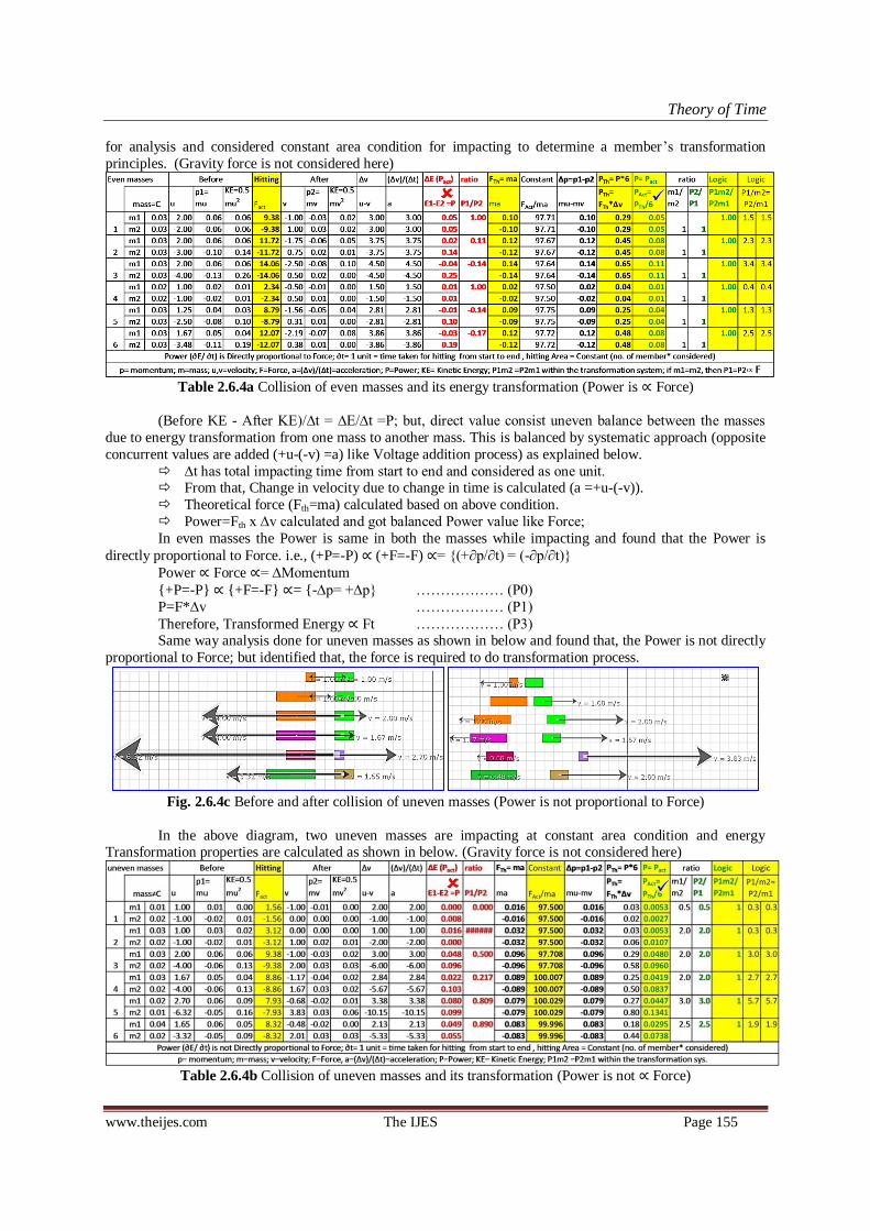
Theory of Time
www.theijes.com The IJES Page 155
for analysis and considered constant area condition for impacting to determine a member‘s transformation
principles. (Gravity force is not considered here)
Table 2.6.4a Collision of even masses and its energy transformation (Power is ∝ Force)
(Before KE - After KE)/∆t = ∆E/∆t =P; but, direct value consist uneven balance between the masses
due to energy transformation from one mass to another mass. This is balanced by systematic approach (opposite
concurrent values are added (+u-(-v) =a) like Voltage addition process) as explained below.
∆t has total impacting time from start to end and considered as one unit. From that, Change in velocity due to change in time is calculated (a =+u-(-v)).
Theoretical force (Fth=ma) calculated based on above condition.
Power=Fth x ∆v calculated and got balanced Power value like Force;
In even masses the Power is same in both the masses while impacting and found that the Power is
directly proportional to Force. i.e., (+P=-P) ∝ (+F=-F) ∝= (+∂p/∂t) = (-∂p/∂t)
Power ∝ Force ∝= ∆Momentum
+P=-P ∝ +F=-F ∝= -∆p= +∆p ……………… (P0)
P=F*∆v ……………… (P1)
Therefore, Transformed Energy ∝ Ft ……………… (P3) Same way analysis done for uneven masses as shown in below and found that, the Power is not directly
proportional to Force; but identified that, the force is required to do transformation process.
Fig. 2.6.4c Before and after collision of uneven masses (Power is not proportional to Force)
In the above diagram, two uneven masses are impacting at constant area condition and energy Transformation properties are calculated as shown in below. (Gravity force is not considered here)
Table 2.6.4b Collision of uneven masses and its transformation (Power is not ∝ Force)
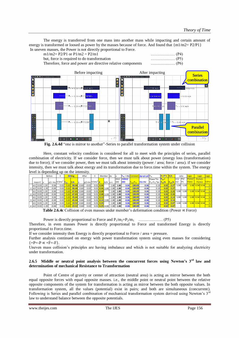
Theory of Time
www.theijes.com The IJES Page 156
The energy is transferred from one mass into another mass while impacting and certain amount of
energy is transformed or loosed as power by the masses because of force. And found that m1/m2= P2/P1
In uneven masses, the Power is not directly proportional to Force. m1/m2= P2/P1 or P1/m2 = P2/m1 ……………… (P4)
but, force is required to do transformation ……………… (P5)
Therefore, force and power are directive relative components ……………… (P6)
Before impacting After impacting
Fig. 2.6.4d ―one is mirror to another‖-Series to parallel transformation system under collision
Here, constant velocity condition is considered for all to meet with the principles of series, parallel
combination of electricity. If we consider force, then we must talk about power (energy loss (transformation) due to force); if we consider power, then we must talk about intensity (power / area; force / area). if we consider
intensity, then we must talk about energy and its transformation due to force.time within the system. The energy
level is depending up on the intensity.
Table 2.6.4c Collision of even masses under member‘s deformation condition (Power ∝ Force)
Power is directly proportional to Force and P1/m2=P2/m1 ……………… (P5)
Therefore, in even masses Power is directly proportional to Force and transformed Energy is directly
proportional to Force.time.
If we consider intensity then Energy is directly proportional to Force / area = pressure.
Further analysis continued on energy with power transformation system using even masses for considering
+P=-P ∝ +F=-F. Uneven mass collision‘s principles are having imbalance and which is not suitable for analyzing electricity
under transformation.
2.6.5 Middle or neutral point analysis between the concurrent forces using Newton’s 3rd
law and
determination of mechanical Resistance to Transformation
Point of Centre of gravity or center of attraction (neutral area) is acting as mirror between the both
equal opposite forces with equal opposite masses. i.e., the middle point or neutral point between the relative
opposite components of the system for transformation is acting as mirror between the both opposite values. In
transformation system, all the values (potential) exist in pairs; and both are simultaneous (concurrent). Following is Series and parallel combination of mechanical transformation system derived using Newton‘s 3rd
law to understand balance between the opposite potentials.
E E ∆v a FTh = ma Constant ∆p=p1-p2 PTh P= P*1 P/A Logic Logic
u p1= mu 0.5mv2
Fact F/A v p2=mv 0.5mv2
A A/A u-v
(∆v)/
(∆t)
m(∆v)/
(∆t) FAct/FTh mu-mvPower*6=
PTh=FTh*∆v
PAct=
PTh/6 Pact/A
m1/
m2
P2/
P1
P1m2/
P2m1 F/P=C
m1 0.03 1.20 0.04 0.02 5.63 90.08 -0.60 -0.02 0.01 0.06 1.80 1.80 0.06 100.09 0.06 0.10 0.02 0.27 1.00 1.00 1.00 0.54 0.54 3.3
m2 0.03 -1.20 -0.04 0.02 -5.63 -90.08 0.60 0.02 0.01 0.06 -1.80 -1.80 -0.06 100.09 -0.06 0.10 0.02 0.27 -3.3
m1 0.03 1.20 0.04 0.02 5.63 67.83 -0.60 -0.02 0.01 0.08 1.80 1.80 0.06 100.09 0.06 0.10 0.02 0.20 1.00 1.00 1.00 0.54 0.54 3.3
m2 0.03 -1.20 -0.04 0.02 -5.63 -67.83 0.60 0.02 0.01 0.08 -1.80 -1.80 -0.06 100.09 -0.06 0.10 0.02 0.20 -3.3
m1 0.03 1.20 0.04 0.02 5.63 45.04 -0.60 -0.02 0.01 0.13 1.80 1.80 0.06 100.09 0.06 0.10 0.02 0.14 1.00 1.00 1.00 0.54 0.54 3.3
m2 0.03 -1.20 -0.04 0.02 -5.63 -45.04 0.60 0.02 0.01 0.13 -1.80 -1.80 -0.06 100.09 -0.06 0.10 0.02 0.14 -3.3
m1 0.03 1.20 0.04 0.02 5.63 22.52 -0.60 -0.02 0.01 0.25 1.80 1.80 0.06 100.09 0.06 0.10 0.02 0.07 1.00 1.00 1.00 0.54 0.54 3.3
m2 0.03 -1.20 -0.04 0.02 -5.63 -22.52 0.60 0.02 0.01 0.25 -1.80 -1.80 -0.06 100.09 -0.06 0.10 0.02 0.07 -3.3
1.00
1.33
2.00
4.00
Hitting After
1
2
3
4
Before ratio Logic
mass=C
P1/m2=
P2/m1
Member
Parallel
combination
Parallel
combination
Series
combination
Series
combination

Theory of Time
www.theijes.com The IJES Page 157
Fig. 2.6.5a Newton‘s 3rd Law under Conversion Process
“Series Combination (attraction process) Parallel Combination (Repel process)”
Above said series parallel combination derived under Newton‘s 3rd law and reviewed as shown in
following to consider time running process within the transformation system. The following design derived to
consider attraction and repletion inside the system under transformation.
Fig. 2.6.5b energy transformation from series to parallel under time running condition
Power is directly proportional to Force; i.e., P∝F
Power : +P1= -P2; +∆E/∆t = -∆E/∆t; +F(∆v) = -F(∆v)
Therefore : Ft∝Etransformed; +F.∆v.t = -F.∆v.t as per Newton‘s 3rd Law
FNeutral = (+F1) + (-F2) = Neutral value = balanced Value
Any potential value (a form) takes certain time to transform them self into ZERO + current form + work done (under energy with power dividing process) due to +ve and –ve actions and reactions; i.e., both +ve
and –ve values required to build a neutral value (potential) and transform them into Zero (past) + current form +
Work done to drive the time wheel (parent child concept). Middle point is acting as mirror between the opposite
concurrent values. Example: one form another form ( = time running process or work in progress);
Mechanical force = Fseries= Fparallel under Transformation
Energy is depending upon the intensity, hence F/A = p ∝ E =Pt
Electrical resistance =R= V/I and equivalent Mechanical Resistance = Rmech. = (Δ Energy/Δ time) /
Member /Total number of members (Refer: 2.2 ) (Note: not as per Ohms law = area constant)
Unique control
Single control
Unique control
Single control
Divided control
Multi control
Divided control
Multi control
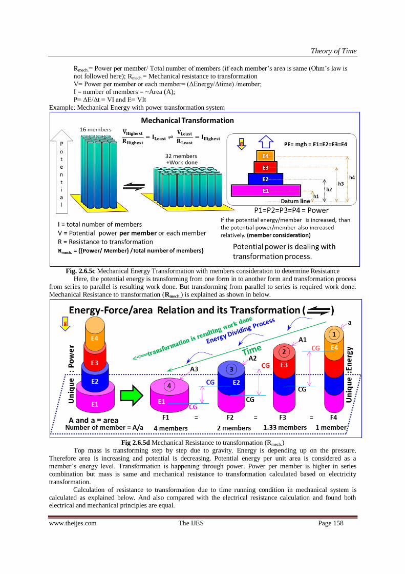
Theory of Time
www.theijes.com The IJES Page 158
Rmech.= Power per member/ Total number of members (if each member‘s area is same (Ohm‘s law is
not followed here); Rmech = Mechanical resistance to transformation
V= Power per member or each member= (ΔEnergy/Δtime) /member; I = number of members = ~Area (A);
P= ΔE/Δt = VI and E= VIt
Example: Mechanical Energy with power transformation system
Fig. 2.6.5c Mechanical Energy Transformation with members consideration to determine Resistance
Here, the potential energy is transforming from one form in to another form and transformation process
from series to parallel is resulting work done. But transforming from parallel to series is required work done.
Mechanical Resistance to transformation (Rmech.) is explained as shown in below.
Fig 2.6.5d Mechanical Resistance to transformation (Rmech.)
Top mass is transforming step by step due to gravity. Energy is depending up on the pressure.
Therefore area is increasing and potential is decreasing. Potential energy per unit area is considered as a
member‘s energy level. Transformation is happening through power. Power per member is higher in series
combination but mass is same and mechanical resistance to transformation calculated based on electricity
transformation.
Calculation of resistance to transformation due to time running condition in mechanical system is
calculated as explained below. And also compared with the electrical resistance calculation and found both electrical and mechanical principles are equal.

Theory of Time
www.theijes.com The IJES Page 159
Mechanical Resistance to Transformation – calculation
Description unit clarification series parallel1 parallel2 parallel3 unit
Total Number of members N 1 1.33 2 4 in numbers
area/ member area 24 24 24 24 m2
Height Height 4 3 2 1 m
Differential potential head (h) head 2 1.5 1 0.5 m
Volume/ member Area. height 96 72 48 24 m3
Density (ρ) mass/ Volume 2 2 2 2 kg/m3
mass/ member mass 192 144 96 48 kg
G acceleration 9.81 9.81 9.81 9.81 m/s2
energy/ member energy 3767.04 2118.96 941.76 235.44 J
transformed mass/ member m' = ∆m 48 48 48 48 kg
Power per member P/member =(∆m/
member)*g*h
941.76 706.32 470.88 235.44 W/member
Mechanical Resistance
(Rmech) to Transformation
Power per
member/ total members
941.76 529.74 235.44 58.86 Ω
Totla Power = P P/member *total
members
941.76 941.76 941.76 941.76 W
Ampere / member (Im) a/a 1 1 1 1 Constant
Total Ampere I = (a/a)*N 1 1.333333 2 4 Ampere
Potential = Total power / Total
Ampere
V 941.76 706.32 470.88 235.44 Volt
Mechanical Resistance
(Rmech) to Transformation
V/I 941.76 529.74 235.44 58.86 Ω
Total Energy = E E/member *total
members
3767.04 2825.28 1883.52 941.76 J
life time = t E/P 4 3 2 1 s
V/h constant 470.88 470.88 470.88 470.88 Logic
Table 2.6.5a Model calculation for Rmech. under transformation (Rmech. = RΩ)
Calculated based on the figure 2.6.5d and found that ―the above calculated results are meeting with the
principles of resistance to transformation of Electricity (R = V/I). Further calculations are done as follow to
confirm that, the similar principles involved in electricity and mechanical.
Differential potential head calculated based on potential difference between the change in mass‘s
Center of gravity (CG) before and after transformation. I could not consider Energy/member for Rmech
calculation due to mismatch w.r.t RElectricity . Above derived calculations are based on Fig. 2.6.5d. Height of the member a= 4m and CG of top mass (∆m) = 4.0 - 0.5 = 3.5m from the base = h‘
Height of the member A1 = 3m and CG of total mass (m) = 3/2 = 1.5 m from the base = h‘‘
Difference = h = h‘-h‘‘ = 3.5 -1.5 =2m = differential potential head
Fig 2.6.5e A member and its transformation (R 1/R) under Electro-Mechanical principles
Mechanical energy with power transformation is equaled with electrical energy with power
transformation and principles behind the both electrical and mechanical resistance to transformation are verified
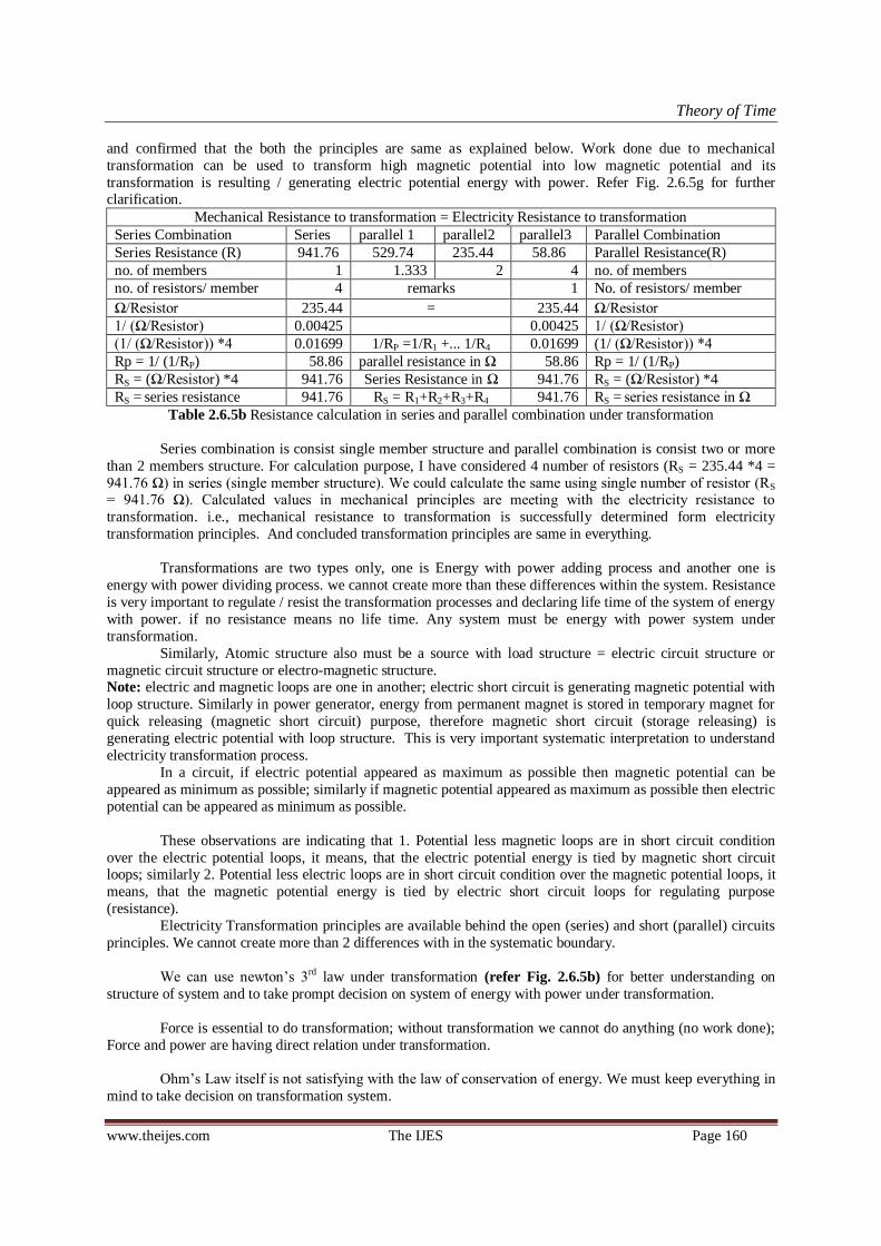
Theory of Time
www.theijes.com The IJES Page 160
and confirmed that the both the principles are same as explained below. Work done due to mechanical
transformation can be used to transform high magnetic potential into low magnetic potential and its
transformation is resulting / generating electric potential energy with power. Refer Fig. 2.6.5g for further clarification.
Mechanical Resistance to transformation = Electricity Resistance to transformation
Series Combination Series parallel 1 parallel2 parallel3 Parallel Combination
Series Resistance (R) 941.76 529.74 235.44 58.86 Parallel Resistance(R)
no. of members 1 1.333 2 4 no. of members
no. of resistors/ member 4 remarks 1 No. of resistors/ member
Ω/Resistor 235.44 = 235.44 Ω/Resistor
1/ (Ω/Resistor) 0.00425 0.00425 1/ (Ω/Resistor)
(1/ (Ω/Resistor)) *4 0.01699 1/RP =1/R1 +... 1/R4 0.01699 (1/ (Ω/Resistor)) *4
Rp = 1/ (1/RP) 58.86 parallel resistance in Ω 58.86 Rp = 1/ (1/RP)
RS = (Ω/Resistor) *4 941.76 Series Resistance in Ω 941.76 RS = (Ω/Resistor) *4
RS = series resistance 941.76 RS = R1+R2+R3+R4 941.76 RS = series resistance in Ω
Table 2.6.5b Resistance calculation in series and parallel combination under transformation
Series combination is consist single member structure and parallel combination is consist two or more
than 2 members structure. For calculation purpose, I have considered 4 number of resistors (RS = 235.44 *4 =
941.76 Ω) in series (single member structure). We could calculate the same using single number of resistor (RS = 941.76 Ω). Calculated values in mechanical principles are meeting with the electricity resistance to
transformation. i.e., mechanical resistance to transformation is successfully determined form electricity
transformation principles. And concluded transformation principles are same in everything.
Transformations are two types only, one is Energy with power adding process and another one is
energy with power dividing process. we cannot create more than these differences within the system. Resistance
is very important to regulate / resist the transformation processes and declaring life time of the system of energy
with power. if no resistance means no life time. Any system must be energy with power system under
transformation.
Similarly, Atomic structure also must be a source with load structure = electric circuit structure or
magnetic circuit structure or electro-magnetic structure. Note: electric and magnetic loops are one in another; electric short circuit is generating magnetic potential with
loop structure. Similarly in power generator, energy from permanent magnet is stored in temporary magnet for
quick releasing (magnetic short circuit) purpose, therefore magnetic short circuit (storage releasing) is
generating electric potential with loop structure. This is very important systematic interpretation to understand
electricity transformation process.
In a circuit, if electric potential appeared as maximum as possible then magnetic potential can be
appeared as minimum as possible; similarly if magnetic potential appeared as maximum as possible then electric
potential can be appeared as minimum as possible.
These observations are indicating that 1. Potential less magnetic loops are in short circuit condition
over the electric potential loops, it means, that the electric potential energy is tied by magnetic short circuit loops; similarly 2. Potential less electric loops are in short circuit condition over the magnetic potential loops, it
means, that the magnetic potential energy is tied by electric short circuit loops for regulating purpose
(resistance).
Electricity Transformation principles are available behind the open (series) and short (parallel) circuits
principles. We cannot create more than 2 differences with in the systematic boundary.
We can use newton‘s 3rd law under transformation (refer Fig. 2.6.5b) for better understanding on
structure of system and to take prompt decision on system of energy with power under transformation.
Force is essential to do transformation; without transformation we cannot do anything (no work done);
Force and power are having direct relation under transformation.
Ohm‘s Law itself is not satisfying with the law of conservation of energy. We must keep everything in
mind to take decision on transformation system.
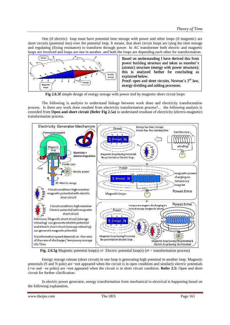
Theory of Time
www.theijes.com The IJES Page 161
One (if electric) loop must have potential time storage with power and other loops (if magnetic) are
short circuits (potential less) over the potential loop. It means, that short circuit loops are tying the time storage
and regulating (fixing resistance) to transform through power. In AC transformer both electric and magnetic loops are involved and loops are one in another. and both the loops are depending each other for transformation.
Fig 2.6.5f simple design of energy storage with power tied by magnetic short circuit loops
The following is analysis to understand linkage between work done and electricity transformation
process. Is there any work done resulted from electricity transformation process?... the following analysis is
extended from Open and short circuit (Refer Fig 2.5a) to understand resultant of electricity (electro-magnetic)
transformation process.
Fig. 2.6.5g Magnetic potential loop(s) Electric potential loop(s) ( = transformation process)
Energy storage release (short circuit) in one loop is generating high potential in another loop. Magnetic
potentials (S and N pole) are ~not appeared when the circuit is in open condition and similarly electric potentials
(+ve and –ve poles) are ~not appeared when the circuit is in short circuit condition. Refer 2.5: Open and short
circuit for further clarification.
In electric power generator, energy transformation from mechanical to electrical is happening based on
the following explanation.
Based on understanding I have derived this from
power building structure and taken as member‘s
(atomic) structure (energy with power structure);
this is analyzed further for concluding as
explained below.
Proof: open and short circuits, Newton‘s 3rd law,
energy dividing and adding processes.
Based on understanding I have derived this from
power building structure and taken as member‘s
(atomic) structure (energy with power structure);
this is analyzed further for concluding as
explained below.
Proof: open and short circuits, Newton‘s 3rd law,
energy dividing and adding processes.

Theory of Time
www.theijes.com The IJES Page 162
Fig. 2.6.5h Transformation is resulting Work Done, mass is not imposed = is supporting agent
Speed from resultant KE
imposed with magnetic
energy normal flow
speed. i.e., magnetic least
mass with maximum flow
speed is involved .
Speed from resultant KE
imposed with magnetic
energy normal flow
speed. i.e., magnetic least
mass with maximum flow
speed is involved .

Theory of Time
www.theijes.com The IJES Page 163
Mechanical energy transformation from high potential to low potential is resulting work done and that
work done is used for transforming magnetic energy from one form to another. i.e., magnetic energy with power
transformation is resulting electric energy with power. i.e., high potential magnetic member (loop) is transforming into least potential magnetic members and resulting generation of electric potential in electric loop.
Fig. 2.6.5i potential energy with power transformation and its results - verified
Electric potential transformation is resulting generation of magnetic potential. Similarly magnetic
potential transformation is resulting generation of electric potential. which is explained and clarified as shown in
above. i.e., mass transformation is resulting work done, and obtained work done can be used to transform
magnetic energy with power, but the mass is not imposed or increased or added. i.e., Work done is outcome of
the transformation process and can be used to transform other energy with power from one form into another
form.
Electricity and mechanical transformation relational principles clarified as explained above and found
both are having direct relation. Force is essential to do transformation. Therefore we can use newton‘s 3rd law
for analyzing energy with power transformation process. (Quick energy transformation in one loop is generating
highest potential in another loop and tying the time storage as energy and regulating for transformation. )
Fig. 2.6.5j Electric and Magnetic transformation cycle (refer open and short circuits)
Transformation loop structure: (R 1/R + resulting high potential magnetic loop) and (high potential
magnetic loop is transforming into Low potential magnetic loops + resulting high potential electric loop) –
Proof: AC Transformer and Open and short circuits.
Transformation system’s loop structure is … Resulted
= ILeast (
=IHighest + Resulting
= MembersLeast) (
= MembersHighest + Resulting
= ILeast
…) i.e., Electric transformation system Magnetic Transformation system

Theory of Time
www.theijes.com The IJES Page 164
i.e., R 1/R = Electric Magnetic
Electric potential transformation is resulting magnetic potential and magnetic potential transformation
is resulting electric potential under time running condition. One end talking about electric and other end talking about magnetic, but both are coming under electro- magnetic transformation system. Both electric and magnetic
transformation systems are driving the time for ever without fail. Without transformation the time cannot run to
do something. Based on this analysis, we could understand that the time running system can survive for ever
without fail under transformation.
Number system: considered based on Newton‘s 3rd Law and electricity potential structure.
+1,+2,+3... +ve values ; -1, -2, -3 ... –ve value ; 1, 2, 3, ... Neutral value
0=null value or universal value or past value; i.e., a form of value contain both +ve and -ve simultaneous
potential in systematic way (+ve Vs -ve). This will transform into Zero + another form + Work done by time
running process (Ampere w/o voltage has ~no value) due to energy with power dividing and adding process. So
that, the time is running based on +ve Vs –ve inter actions for dividing themselves to do something (work done).
the system must transform themselves into least values of many most members for doing energy with power adding process. Note: the dividing process is resulting work done.
In the above diagram (Fig 2.6.5b), neutral point or area between the opposite masses is acting as mirror
to build potential in systematic way and divide themselves through energy with power transformation process
for driving the time.
Mass energy is considered as internal energy and work done due to mass transformation is considered
as resultant or external factor. Work done (mass is supporting agent) is performed because of mass
transformation process (energy with power transformation); but, resultant work done (speed) can be transposed
into mass energy (ex. in power generator: least electric mass with ‗most flow speed obtained from Work done‘.)
2.6.6 Mirror Rule + Newton’s 3rd
Law for analyzing energy under transformation building structure
Energy under transformation structure is a power building structure as per ac transformer.
=
(-Ve) Mirror Area (+Ve)
Fig. 2.6.6a Newton‘s 3rd Law with Mirror rule for analyzing ∆E/∆t (Power) building Structure
Mirror rule: The neutral point or area (system‘s Center of attraction) between +ve and –ve potential is acting as
mirror (a) to build up the potential value in opposite direction in systematic balanced condition; (b) and to
transform the built energy into another form of energy through/ via power to run the time wheel due to +ve and –ve potential. Mirror rule can help us to understand the energy transformation processes. We must know how
the 2 opposite potentials were built from the base of neutral (common one) and we can analysis the flow rate,
velocity, structure, speed, time running speed etc. by using mirror rule + Newton‘s 3rd law + energy with power
transformation structure. i.e., wherever force is there should have Energy Transformation process (Power =P
=∆E/∆t);ie, adding or dividing processes only.
Proof: Newton‘s Laws, battery (energy) with light bulb (power), series and parallel combination under
transformation, Power transformer, capacitor storages, magnet, Force under transformation, etc. The followings
are interpreted based on mirror rule and newton‘s 3rd law.
(-Ve) Mirror Area (+Ve)
<= Force <=0=> anti force=>
0=>Force => Value <= anti force<=0
Both Left hand and right hand value of forces are opposite and mirror to one another.
Both Left hand and right hand value of forces are opposite and mirror to one another.
Opposite relation between one another with in the system; this is
logics for creating relations.
Opposite relation between one another with in the system; this is
logics for creating relations.
How to create a different? How to relate each other? 3D Formulation will help us to
analyze the relativity easily.
How to create a different? How to relate each other? 3D Formulation will help us to
analyze the relativity easily.

Theory of Time
www.theijes.com The IJES Page 165
<=+n ... +3, +2, +1 <=Zero=>-1, -2, -3, ... -n=>
0=>+1,+2,+3...+n=>+ve Value Vs –ve Value<=-n...-3,-2,-1<=0
+
N S
-
S N
N
+ -
S
- + S
STAR
T
STAR
T STAR
T
STAR
T
Source
neutral
Source
neutral
Load neutral Load
neutral
Source
neutral
Source
neutral
Mechanical energy with power structure: The power is generated during impacting. i.e., due to force or acceleration the energy is transforming from one form in to another. Without force the energy transformation cannot be
happened.
Mechanical energy with power structure: The power is generated during impacting. i.e., due to force or acceleration the energy is transforming from one form in to another. Without force the energy transformation cannot be
happened.
Magnetic source with load structure (closed loops) using mirror rule for analyzing force, flow, velocity... (We can do analysis on loop structure using
Newton‘s 3rd law + mirror rule)
Magnetic source with load structure (closed loops) using mirror rule for analyzing force, flow, velocity... (We can do analysis on loop structure using
Newton‘s 3rd law + mirror rule)
Logic for energy transformation: due to closed circuit, the energy from source (time storage) is flowing (based on ampere or conductor thickness) toward opposite pole‘s source due to attraction. While flowing certain amount of energy subtracted by
the load due to attractive force or acceleration (Meeting of high potential energy). Maximum opposite potentials are impacting each other at load and converted themselves as heat ray / light ray / electromagnetic ray or etc. as stored particles under
transformation.
Neutral point or Neutral area is acting as mirror. Magnetic poles
are mirror to one another with respect to force, energy, velocity, flow, matter, structure etc...
(Proof: Magnet and its structure)
Neutral point or Neutral area is acting as mirror. Magnetic poles
are mirror to one another with respect to force, energy, velocity, flow, matter, structure etc...
(Proof: Magnet and its structure)
Neutral point or Neutral area is acting as mirror. Electric poles are mirror to one another with respect to force, energy flow, velocity, mass flow, matter structure etc... Electric and magnetic loops are
one in another.
Neutral point or Neutral area is acting as mirror. Electric poles are mirror to one another with respect to force, energy flow, velocity, mass flow, matter structure etc... Electric and magnetic loops are
one in another.
Load
neutral
Load
neutral
Both Left hand and right hand windings (two different windings) are opposite to one
another. But these are derived
from the one of Neutral value.
Both Left hand and right hand windings (two different windings) are opposite to one
another. But these are derived
from the one of Neutral value.
Logic: One Two; the one is
Neutral; and the twos are both
Positive and negative value.
Logic: One Two; the one is
Neutral; and the twos are both
Positive and negative value.
Source Source
Load Load
𝐏𝐨𝐬𝐢𝐭𝐢𝐯𝐞 𝐕𝐨𝐥𝐭𝐚𝐠𝐞 । 𝐍𝐞𝐠𝐚𝐭𝐢𝐯𝐞 𝐕𝐨𝐥𝐭𝐚𝐠𝐞
Source (releasing)
Load (storing)
𝐏𝐨𝐬𝐢𝐭𝐢𝐯𝐞 𝐕𝐨𝐥𝐭𝐚𝐠𝐞 । 𝐍𝐞𝐠𝐚𝐭𝐢𝐯𝐞 𝐕𝐨𝐥𝐭𝐚𝐠𝐞
Source (releasing)
Load (storing)
𝐏𝐨𝐬𝐢𝐭𝐢𝐯𝐞 𝐖𝐢𝐧𝐝𝐢𝐧𝐠 । 𝐍𝐞𝐠𝐚𝐭𝐢𝐯𝐞 𝐖𝐢𝐧𝐝𝐢𝐧𝐠
Two
One
𝐏𝐨𝐬𝐢𝐭𝐢𝐯𝐞 𝐖𝐢𝐧𝐝𝐢𝐧𝐠 । 𝐍𝐞𝐠𝐚𝐭𝐢𝐯𝐞 𝐖𝐢𝐧𝐝𝐢𝐧𝐠
Two
One
Concurrent potential values
under transformation.
Concurrent potential values
under transformation.
Paper roll Paper roll
Electro-Magnetism Electro-Magnetism
0 = source for transformation. Value = potential (+ve and –ve) Values are built from source. Built Values are transforming to
drive the time due to force.
0 = source for transformation. Value = potential (+ve and –ve) Values are built from source. Built Values are transforming to
drive the time due to force.

Theory of Time
www.theijes.com The IJES Page 166
System interpretation is
Power Building Structure under Newton’s 3
rd Law + mirror rule
(Energy building structure under transformation = energy with power building structure)
We cannot / could not create more than 2 differences within the systematic link or boundary.
𝐏𝐨𝐬𝐢𝐭𝐢𝐯𝐞 𝐕𝐚𝐥𝐮𝐞 । 𝐍𝐞𝐠𝐚𝐭𝐢𝐯𝐞 𝐕𝐚𝐥𝐮𝐞 Two (Value(s)) potential
One (Zero + WD)
𝐏𝐨𝐬𝐢𝐭𝐢𝐯𝐞 𝐕𝐚𝐥𝐮𝐞 । 𝐍𝐞𝐠𝐚𝐭𝐢𝐯𝐞 𝐕𝐚𝐥𝐮𝐞 Two (Value(s)) potential
One (Zero + WD)
Two
𝐏𝐨𝐬𝐢𝐭𝐢𝐯𝐞 𝐫𝐮𝐧𝐧𝐢𝐧𝐠 । 𝐍𝐞𝐠𝐚𝐭𝐢𝐯𝐞 𝐫𝐮𝐧𝐧𝐢𝐧𝐠
One
Two
𝐏𝐨𝐬𝐢𝐭𝐢𝐯𝐞 𝐫𝐮𝐧𝐧𝐢𝐧𝐠 । 𝐍𝐞𝐠𝐚𝐭𝐢𝐯𝐞 𝐫𝐮𝐧𝐧𝐢𝐧𝐠
One
Capacitor’s
Source neutral
Capacitor’s
Source neutral
Capacitor’s
Load
neutral
Capacitor’s
Load
neutral
Capacitor‘s energy with power building structure including
members consideration is meeting with the transformation
theory.
Capacitor‘s energy with power building structure including
members consideration is meeting with the transformation
theory.
Both the winding are opposite to one another at the same time mirror to one another. We can get Loop structure by adding of both
the type of windings.
Both the winding are opposite to one another at the same time mirror to one another. We can get Loop structure by adding of both
the type of windings.
Source and load both are essential to do energy transformation process. i.e., energy with power is running the
time wheel through
transformation.
Source and load both are essential to do energy transformation process. i.e., energy with power is running the
time wheel through
transformation.
We cannot create more
than 2 different within the
transformation system
(relativity).
We cannot create more
than 2 different within the
transformation system
(relativity). Running wheel under mirror rule is as shown. i.e., two differences created from the one. One is opposite to another and mirror to
one another.
Running wheel under mirror rule is as shown. i.e., two differences created from the one. One is opposite to another and mirror to
one another.
Power building structure under mirror rule is shown. Opposite potential value is increasing gradually from the neutral area. It indicates energy building structure; but maximum potential value is meeting at load, which
creates high pressure and leads to storing of energy at load for
subtracting from source.
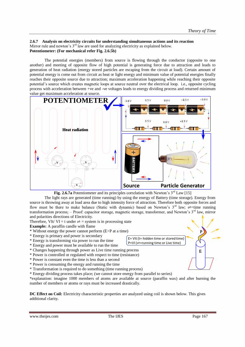
Theory of Time
www.theijes.com The IJES Page 167
2.6.7 Analysis on electricity circuits for understanding simultaneous actions and its reaction
Mirror rule and newton‘s 3rd law are used for analyzing electricity as explained below.
Potentiometer: (For mechanical refer Fig. 2.6.5b)
The potential energies (members) from source is flowing through the conductor (opposite to one
another) and meeting of opposite flow of high potential is generating force due to attraction and leads to
generation of heat radiation (energy stored particles are escaping from the circuit at load). Certain amount of
potential energy is come out from circuit as heat or light energy and minimum value of potential energies finally
reaches their opposite source due to attraction; maximum acceleration happening while reaching their opposite
potential‘s source which creates magnetic loops at source neutral over the electrical loop. i.e., opposite cycling
process with acceleration between +ve and -ve voltages leads to energy dividing process and returned minimum
value get maximum acceleration at source.
Fig. 2.6.7a Potentiometer and its principles correlation with Newton‘s 3rd Law [15]
The light rays are generated (time running) by using the energy of Battery (time storage). Energy from
source is throwing away at load area due to high intensity force of attraction. Therefore both opposite forces and
flow must be there to make balance (Static with dynamic) based on Newton‘s 3rd law; =time running
transformation process; – Proof: capacitor storage, magnetic storage, transformer, and Newton‘s 3rd law, mirror and polarities directions of Electricity.
Therefore, VIt/ VI = t under = system is in processing state
Example: A paraffin candle with flame
* Without energy the power cannot perform (E>P at a time)
* Energy is primary and power is secondary
* Energy is transforming via power to run the time
* Energy and power must be available to run the time
* Changes happening through power as Live time running process
* Power is controlled or regulated with respect to time (resistance)
* Power is constant even the time is less than a second
* Power is consuming the energy and running the time * Transformation is required to do something (time running process)
* Energy dividing process takes place; (we cannot store energy from parallel to series)
*explanation: imagine 1000 members of atoms are available at source (paraffin wax) and after burning the
number of members or atoms or rays must be increased drastically.
DC Effect on Coil: Electricity characteristic properties are analyzed using coil is shown below. This gives
additional clarity.
POTENTIOMETERPOTENTIAL PRINCIPLE
V
V
V
Heat radiation Heat radiation
E E
P P

Theory of Time
www.theijes.com The IJES Page 168
Fig. 2.6.7b Effect of DC on coil -from Current theories and verified
1. First give supply to coil through one pole two-way switch.
2. Battery act as a source (<<<Energy>>>)
3. Coil act as a load (>>>Power<<<)
4. Some amount of energy stored in coil as electro-magnetic induction. (<<<Energy>>>)
5. Now, interchange the position of switch. 6. Coil act as a source and Ampere meter act as a load, Energy from charged coil is discharging to ampere
meter). (We can subtract source energy (both +ve and –ve))
But polarity of this voltage is opposite to the polarity of battery. i.e., indicates ―Opposite flow to one
another‖). The circuit is in closed condition, so that the magnetic loops are generated over the electric loop.
Energy in Source is greater than the load in systematic way. Therefore, both +ve and –ve voltage is flowing
opposite to one another from source through load (Energy is directly proportional to Pressure) due to closed
circuit and attraction process between potentials.
―Source load‖ indicates loop structure; ―Opposite flow of positive and negative voltage (members)
from source (potential) is happening (because of repel of same pole members and attraction of opposite pole
members) toward opposite poles of source due to attraction; due to flow (ampere) magnetic short circuit loops
are getting potential and stored in winding core as magnetic energy with power (with magnetic resistance). This is explained in the following. (i.e., energy from source is moving to load and transformed as magnetic energy at
load due to electric flow attraction + acceleration between both +ve and –ve voltage. then stored magnetic
energy releasing its energy through magnetic power with respect to running of time)
=
-
-
+
+A
+
DC EFFECT
-
Fig. 2.6.7c Electro Magnetism – Loops Fig. 2.6.7d Load Source
While interchanging the switch the stored energy in coil is divided (This is called energy dividing process from the source energy.) from the source of battery and magnetic energy released (dividing process) due
to temporary magnetic condition (magnetic short circuit(s).
As per Newton‘s 3rd Law, the both +ve and –ve voltage should flow toward their opposite source due to
attraction and to show the VALUE of Energy at load due to peak potential as power for dividing the energy
from the source to drive the time wheel (transformation). In the above diagram, Considered each closed loops as
each member in both electric and magnetic circuit. Both are mingled in system, we cannot separate either
electric or magnetic circuit from the system of energy with power loop. Both the loops are one in another. This
-
-
+
+A
+
DC EFFECT
-
S
SECTIONAL VIEW
-
+
+
---
N
Energy Compression
(time storage)
Energy Compression
(time storage)
Energy expansion
(time running)
Energy expansion
(time running)

Theory of Time
www.theijes.com The IJES Page 169
is meeting with the above said derivation. This is energy with power structure. Any circuit can meet with this
structure. Here, we could understand the importance of members. i.e., resistance/member is higher than the total
system‘s resistance. i.e., Members (number of flux lines or number of turns or loops) came out from the source polarities and expanding due to Repel force between the same, at the same time, the expanded members
narrowed at opposite polarities due to attraction force between opposite polarities. This is increasing high
intensity/ member at load for dividing process.
Fig. 2.6.7e two types of windings (only) and its polarities direction
Here, two types (only) of windings are connected with DC power supply and its polarity directions
observed is as shown in above. Observed results are placed systematically as shown in below to relate each
other by using Newton‘s 3rd law and mirror rule for further building up.
Fig. 2.6.7f Result: Polarities direction on windings under Newton‘s 3rd Law +mirror rule
―One pole is mirror to another pole with in the system boundary‖
Left and right hand thread type windings are opposite to one another and mirror to one another, therefore we can consider, one is positive and another one is negative. By adding of both we can bring these
under unique one. i.e., The unique one is considered as neutral thing, which contain neutral value, and the twos
are considered as different things. But both are simultaneous (concurrent) opposite values derived from neutral
one. We can define this as said in following using mirror rule.
NEUTRAL WINDING = LEFT HAND WINDING + RIGHT HAND WINDING = NEUTRAL RING
Fig. 2.6.7g relation between neutral value and mirrored potential values
These results are same as result of ordinary circuit. One winding is mirror to another winding. And the
properties are also mirror to one another as said above. By adding the both the windings, we can convert these
twos into one as loop, and which indicates closed circuit. (And found there are two different windings only
possible within the system.)
Result of each winding loops are same: Thread type winding is not necessary consideration to generate polarity. Here, more number of turns of winding is considered as one circle to reduce difference between them –
this consideration was taken based on neutral point view.
Loop
Structure
Loop
Structure
Relativity Relativity
One One
Two Two
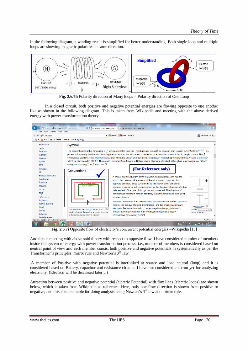
Theory of Time
www.theijes.com The IJES Page 170
In the following diagram, a winding result is simplified for better understanding. Both single loop and multiple
loops are showing magnetic polarities in same direction.
=
Fig. 2.6.7h Polarity direction of Many loops = Polarity direction of One Loop
In a closed circuit, both positive and negative potential energies are flowing opposite to one another
like as shown in the following diagram. This is taken from Wikipedia and meeting with the above derived
energy with power transformation theory.
Fig. 2.6.7i Opposite flow of electricity‘s concurrent potential energies –Wikipedia [15]
And this is meeting with above said theory with respect to opposite flow. I have considered number of members
inside the system of energy with power transformation process, i.e., number of members is considered based on
neutral point of view and each member consist both positive and negative potentials in systematically as per the
Transformer‘s principles, mirror rule and Newton‘s 3rd law.
A member of Positive with negative potential is interlinked at source and load neutral (loop) and it is
considered based on Battery, capacitor and resistance circuits. I have not considered electron yet for analyzing electricity. (Electron will be discussed later…)
Attraction between positive and negative potential (electric Potential) with flux lines (electric loops) are shown
below, which is taken from Wikipedia as reference. Here, only one flow direction is shown from positive to
negative; and this is not suitable for doing analysis using Newton‘s 3rd law and mirror rule.
(For Reference only) (For Reference only)
Simplified Simplified

Theory of Time
www.theijes.com The IJES Page 171
Fig. 2.6.7j One side flow within electricity –Wikipedia [10]
Based on Newton‘s 3rd law + mirror rule the following structure designed and taken for analysis. Based
on above said principles of transformation system, opposite flow with magnetism, source with load (loop)
conditions are essential for analyzing using Newton‘s 3rd law + mirror rule.
Fig 2.6.7k Mirror flow structure of energy within electricity – based on Newton‘s 3rd law + mirror
This is derived based on Equal force of action (-F) = reaction (+F) and opposite mirror flow of equal
energy (another proof: Capacitor storage, both +ve and –ve potential energies stored opposite to one another in
parallel plates). The magnetic loops are created over the electric loop due to electric closed loop; In poles, the
members are in joined together and showing unique strength, flux lines are expanding due to repel action
between the same pole members and narrowing due to attraction at opposite pole‘s members.
Example: Mechanical wheel under mirror rule + Newton‘s 3rd law A running mechanical wheel condition interpreted using mirror rule is shown below having simple explanation
to understand concurrent values = mirrored value.
Fig. 2.6.7l: Running Wheel with mirror rule for showing 2 different values (only)
Left side View <<= running Wheel Elevation =>> Right side View
One (neutral) Two (Potential)
(For Reference only) (For Reference only)
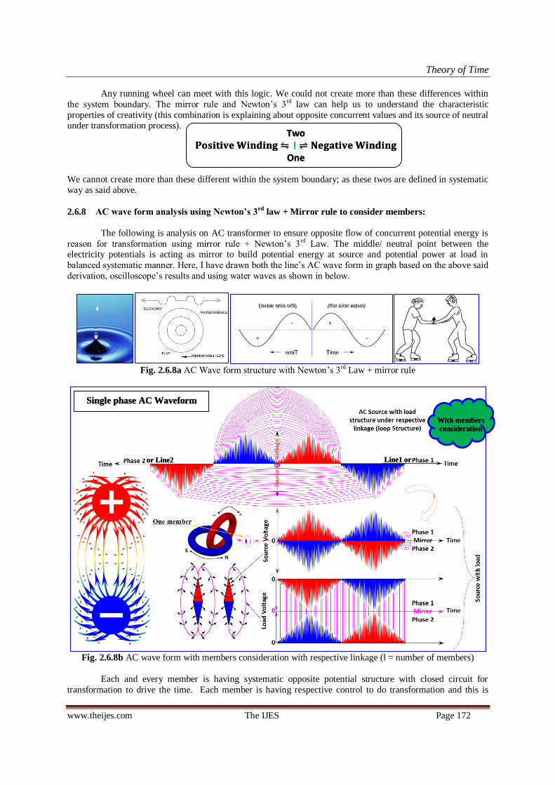
Theory of Time
www.theijes.com The IJES Page 172
Any running wheel can meet with this logic. We could not create more than these differences within
the system boundary. The mirror rule and Newton‘s 3rd law can help us to understand the characteristic
properties of creativity (this combination is explaining about opposite concurrent values and its source of neutral under transformation process).
We cannot create more than these different within the system boundary; as these twos are defined in systematic
way as said above.
2.6.8 AC wave form analysis using Newton’s 3rd
law + Mirror rule to consider members:
The following is analysis on AC transformer to ensure opposite flow of concurrent potential energy is
reason for transformation using mirror rule + Newton‘s 3rd Law. The middle/ neutral point between the electricity potentials is acting as mirror to build potential energy at source and potential power at load in
balanced systematic manner. Here, I have drawn both the line‘s AC wave form in graph based on the above said
derivation, oscilloscope‘s results and using water waves as shown in below.
Fig. 2.6.8a AC Wave form structure with Newton‘s 3rd Law + mirror rule
Fig. 2.6.8b AC wave form with members consideration with respective linkage (l = number of members)
Each and every member is having systematic opposite potential structure with closed circuit for
transformation to drive the time. Each member is having respective control to do transformation and this is
With members
consideration
With members
consideration
Single phase AC Waveform Single phase AC Waveform
or Line2 or Line2 Line1 or Line1 or
𝐏𝐨𝐬𝐢𝐭𝐢𝐯𝐞 𝐖𝐢𝐧𝐝𝐢𝐧𝐠 । 𝐍𝐞𝐠𝐚𝐭𝐢𝐯𝐞 𝐖𝐢𝐧𝐝𝐢𝐧𝐠 Two
One 𝐏𝐨𝐬𝐢𝐭𝐢𝐯𝐞 𝐖𝐢𝐧𝐝𝐢𝐧𝐠 । 𝐍𝐞𝐠𝐚𝐭𝐢𝐯𝐞 𝐖𝐢𝐧𝐝𝐢𝐧𝐠
Two
One

Theory of Time
www.theijes.com The IJES Page 173
shown in the above said diagram. Each member is having energy building structure with transformation (power)
to drive the time. Neutral point or area between the attracting opposite flow is acting as mirror for making
balance. Without force, the transformation cannot happen.
AC wave form structure and control linkage is explained with members consideration and rectified
wave form also explained as shown in following.
Fig. 2.6.8c AC Wave form with DC Rectifier
Both +ve and –ve potentials are having opposite relation to each other as per mirror rule. Mirror rule is
a thump rule to understand the flow, structure, velocity, force, etc...
As per above AC transformer‘s conversion principles, the wave form structure should have both
simultaneous directions as said in above and both are relative to each other. i.e., ―a energy with power structure
has 2 faces; Both are relative to each other & both are mirror to each other‖. Since, we cannot show a +ve value
without –ve value under balanced condition. Both the loops are inter-linked within the system as shown in following diagram.
Fig. 2.6.8d One is mirror to another within the system–Proof (2 differences only possible)
Both the loops are one in another and polarities are opposite to one another, ‗at the same time‘, mirror
to one another. The following waveform designed based on without members consideration inside the system.
;
Fig. 2.6.8e AC Transformer with DC converter and graph (“One is opposite to another”)
With members
consideration
With members
consideration
Energy with Power building structure Energy with Power building structure
Designed
on 2000
Designed
on 2000
Without
members
consideration
Without
members
consideration

Theory of Time
www.theijes.com The IJES Page 174
Above said AC and DC wave form is derived using mirror rule during the year of 2000.
At the time, I have introduced no. of members availability inside the system. But, which was not calibrated
using mechanical theories.
Fig. 2.6.8f 3D AC mirror waveform with members consideration – derived
Both are inter-linked as systematic way as shown in following.
50% Positive Voltage<= Mirror area =>(50%)Negative Voltage (logic for source)
50% Positive Voltage => Mirror area <= 50% Negative Voltage (logic for load)
50% Positive Value Mirror area 50% Negative Value (Logic for source with load)
Neutral area is always acting as mirror between the concurrent actions or Potentials.
As per the above derivation, ―one is opposite to another‖, therefore we can consider that, one as
Positive and another one as Negative (+ve Vs –Ve). Therefore we can bring these two under transformation
condition due to force. i.e., Force is directly proportional to Power at the same time power is directly
proportional to Force. A Value B Value + resulting work done; power is live transformation process.
Fig. 2.6.8g Simple potential building structure with mirror rule (under Newton‘s 3rd Law)
In AC transformer, input AC supply‘s polarities directions are changing frequently, which resulting
change in magnetic polarities directions (based on, If electric potential appeared as maximum as possible, then
magnetic potential can be appeared as minimum as possible; similarly, If magnetic potential appeared as
maximum as possible, then electric potential can be appeared as minimum as possible under transformation);
i.e., electric potential intensity is reducing and increasing magnetic potential due to increase in ampere or current. (Reason, the Ampere (I) is inversely proportional to Voltage (V) under transformation; therefore,
magnetic polarity intensity is increasing due to increase in ampere). That is, electric energy with power is
transforming and resulting work done or magnetic energy with power is transforming and resulting work done
under transformation. Resultant Work done can be used to transform other energy with power. Magnetic
potential and electric potential both are inversely proportional under transformation.
𝐏𝐨𝐬𝐢𝐭𝐢𝐯𝐞 𝐕𝐨𝐥𝐭𝐚𝐠𝐞 । 𝐍𝐞𝐠𝐚𝐭𝐢𝐯𝐞 𝐕𝐨𝐥𝐭𝐚𝐠𝐞
Source
Load
𝐏𝐨𝐬𝐢𝐭𝐢𝐯𝐞 𝐕𝐨𝐥𝐭𝐚𝐠𝐞 । 𝐍𝐞𝐠𝐚𝐭𝐢𝐯𝐞 𝐕𝐨𝐥𝐭𝐚𝐠𝐞
Source
Load
Designed
on 2010
Designed
on 2010
With members
consideration
With members
consideration

Theory of Time
www.theijes.com The IJES Page 175
Example: DC and AC effect on coil, cycle dynamo. In cycle dynamo, the permanent magnetic potential energy
is stored (power.time) in temporary magnet, the stored potential energy is released (PE is transforming into KE)
while we change the polarity direction by rotating the rotor (i.e., the stored magnetic potential is reduced and increasing the Electric potential while releasing.) rotor speed engaged with releasing speed, so work done is
engaged with magnetic transformation. Conservation of momentum is playing major role.
Proofs: Concurrent flow of two opposite (+ve & -ve) relative energies within the transformation system (energy
with power system): Verified using oscilloscope is shown in below.
Fig. 2.6.8h Half wave rectifier, (4 nos of half cycle AC wave form =4nos of half cycle DC waveform)
Here, i have shown one line wave form in AC and DC by using rectifier. One line wave form is
opposite or mirror to another line wave form as shown in following.
Fig. 2.6.8i Full wave rectifier (secondary voltage = V/2)
Logic: 8 nos of half cycle AC wave form = 8 nos of half cycle DC waveform
Fig 2.6.8j Bridge Rectifier (secondary utilized voltage = V)
Logic: 8 nos of half cycle AC wave form = 8 nos of half cycle DC waveform
One line flow is mirror to another line flow and opposite relation between them. Neutral area (both
source and load) is acting as mirror in each and every phase. High potential +ve and –ve energy is meeting
opposite to one another at load due to attraction and creates force with high intensity/member. Source neutral is
having low intensity due to more area.
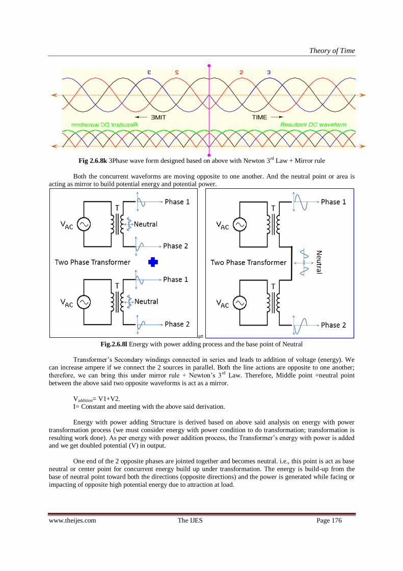
Theory of Time
www.theijes.com The IJES Page 176
Fig 2.6.8k 3Phase wave form designed based on above with Newton 3rd Law + Mirror rule
Both the concurrent waveforms are moving opposite to one another. And the neutral point or area is acting as mirror to build potential energy and potential power.
Fig.2.6.8l Energy with power adding process and the base point of Neutral
Transformer‘s Secondary windings connected in series and leads to addition of voltage (energy). We
can increase ampere if we connect the 2 sources in parallel. Both the line actions are opposite to one another;
therefore, we can bring this under mirror rule + Newton‘s 3rd Law. Therefore, Middle point =neutral point
between the above said two opposite waveforms is act as a mirror.
Vaddition= V1+V2.
I= Constant and meeting with the above said derivation.
Energy with power adding Structure is derived based on above said analysis on energy with power
transformation process (we must consider energy with power condition to do transformation; transformation is
resulting work done). As per energy with power addition process, the Transformer‘s energy with power is added and we get doubled potential (V) in output.
One end of the 2 opposite phases are jointed together and becomes neutral. i.e., this point is act as base
neutral or center point for concurrent energy build up under transformation. The energy is build-up from the
base of neutral point toward both the directions (opposite directions) and the power is generated while facing or
impacting of opposite high potential energy due to attraction at load.
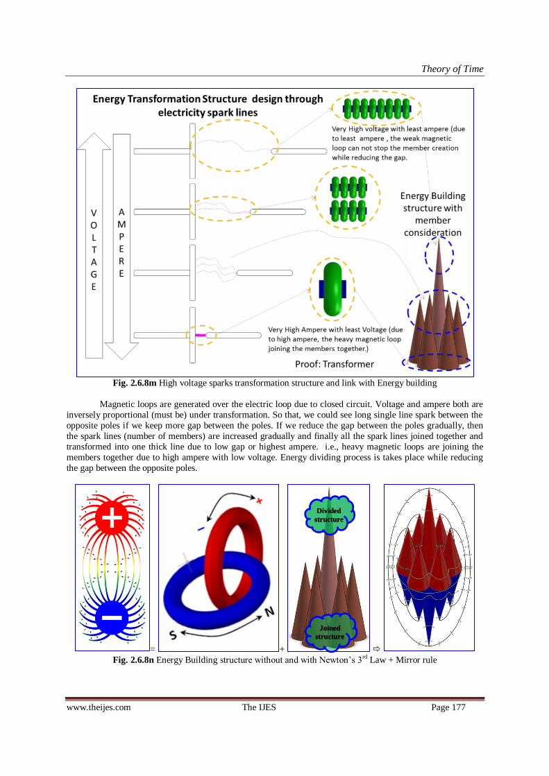
Theory of Time
www.theijes.com The IJES Page 177
Fig. 2.6.8m High voltage sparks transformation structure and link with Energy building
Magnetic loops are generated over the electric loop due to closed circuit. Voltage and ampere both are
inversely proportional (must be) under transformation. So that, we could see long single line spark between the
opposite poles if we keep more gap between the poles. If we reduce the gap between the poles gradually, then
the spark lines (number of members) are increased gradually and finally all the spark lines joined together and
transformed into one thick line due to low gap or highest ampere. i.e., heavy magnetic loops are joining the
members together due to high ampere with low voltage. Energy dividing process is takes place while reducing
the gap between the opposite poles.
= +
Fig. 2.6.8n Energy Building structure without and with Newton‘s 3rd Law + Mirror rule
Joined
structure
Joined
structure
Divided
structure
Divided
structure
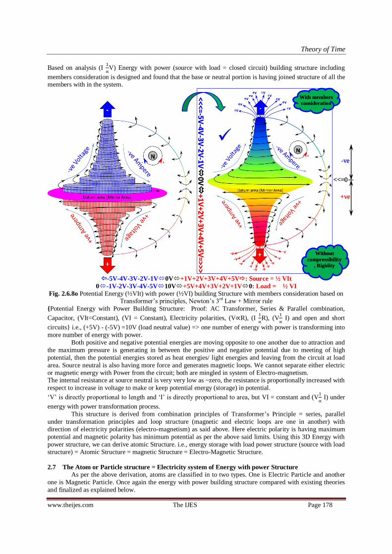
Theory of Time
www.theijes.com The IJES Page 178
Based on analysis (I
∝V) Energy with power (source with load = closed circuit) building structure including
members consideration is designed and found that the base or neutral portion is having joined structure of all the members with in the system.
-5V-4V-3V-2V-1V0V+1V+2V+3V+4V+5V: Source = ½ VIt
0-1V-2V-3V-4V-5V10V+5V+4V+3V+2V+1V0: Load = ½ VI
Fig. 2.6.8o Potential Energy (½VIt) with power (½VI) building Structure with members consideration based on Transformer‘s principles, Newton‘s 3rd Law + Mirror rule
Potential Energy with Power Building Structure: Proof: AC Transformer, Series & Parallel combination,
Capacitor, (VIt=Constant), (VI = Constant), Electricity polarities, (V∝R), (I
∝R), (V
∝ I) and open and short
circuits i.e., (+5V) - (-5V) =10V (load neutral value) => one number of energy with power is transforming into
more number of energy with power.
Both positive and negative potential energies are moving opposite to one another due to attraction and
the maximum pressure is generating in between the positive and negative potential due to meeting of high
potential, then the potential energies stored as heat energies/ light energies and leaving from the circuit at load
area. Source neutral is also having more force and generates magnetic loops. We cannot separate either electric
or magnetic energy with Power from the circuit; both are mingled in system of Electro-magnetism. The internal resistance at source neutral is very very low as ~zero, the resistance is proportionally increased with
respect to increase in voltage to make or keep potential energy (storage) in potential.
‗V‘ is directly proportional to length and ‗I‘ is directly proportional to area, but VI = constant and (V
∝ I) under
energy with power transformation process.
This structure is derived from combination principles of Transformer‘s Principle = series, parallel
under transformation principles and loop structure (magnetic and electric loops are one in another) with
direction of electricity polarities (electro-magnetism) as said above. Here electric polarity is having maximum
potential and magnetic polarity has minimum potential as per the above said limits. Using this 3D Energy with
power structure, we can derive atomic Structure. i.e., energy storage with load power structure (source with load
structure) = Atomic Structure = magnetic Structure = Electro-Magnetic Structure.
2.7 The Atom or Particle structure = Electricity system of Energy with power Structure
As per the above derivation, atoms are classified in to two types. One is Electric Particle and another
one is Magnetic Particle. Once again the energy with power building structure compared with existing theories
and finalized as explained below.
-ve -ve
+ve +ve
<<= <<= 0 0
<<<=-5V-4V
-3V-2V
-1V
0V
+1
V+
2V
+3
V+
4V
+5
V=
>>
>
<<<=-5V-4V
-3V-2V
-1V
0V
+1
V+
2V
+3
V+
4V
+5
V=
>>
>
Without
compressibility
, Rigidity
Without
compressibility
, Rigidity
With members
consideration
With members
consideration
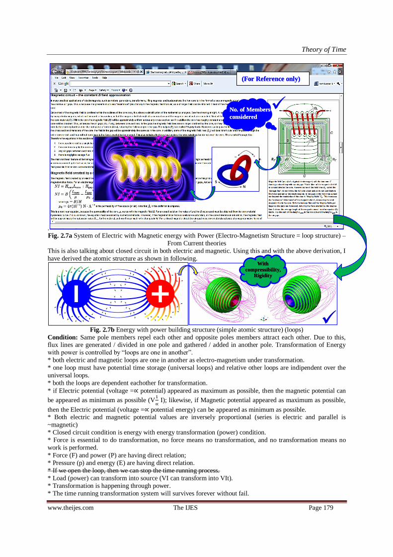
Theory of Time
www.theijes.com The IJES Page 179
. Fig. 2.7a System of Electric with Magnetic energy with Power (Electro-Magnetism Structure = loop structure) –
From Current theories
This is also talking about closed circuit in both electric and magnetic. Using this and with the above derivation, I
have derived the atomic structure as shown in following.
Fig. 2.7b Energy with power building structure (simple atomic structure) (loops)
Condition: Same pole members repel each other and opposite poles members attract each other. Due to this, flux lines are generated / divided in one pole and gathered / added in another pole. Transformation of Energy
with power is controlled by ―loops are one in another‖.
* both electric and magnetic loops are one in another as electro-magnetism under transformation.
* one loop must have potential time storage (universal loops) and relative other loops are indipendent over the
universal loops.
* both the loops are dependent eachother for transformation.
* if Electric potential (voltage =∝ potential) appeared as maximum as possible, then the magnetic potential can
be appeared as minimum as possible (V
∝ I); likewise, if Magnetic potential appeared as maximum as possible,
then the Electric potential (voltage =∝ potential energy) can be appeared as minimum as possible. * Both electric and magnetic potential values are inversely proportional (series is electric and parallel is
~magnetic)
* Closed circuit condition is energy with energy transformation (power) condition.
* Force is essential to do transformation, no force means no transformation, and no transformation means no
work is performed.
* Force (F) and power (P) are having direct relation;
* Pressure (p) and energy (E) are having direct relation.
* If we open the loop, then we can stop the time running process.
* Load (power) can transform into source (VI can transform into VIt).
* Transformation is happening through power.
* The time running transformation system will survives forever without fail.
1
With
compressibility,
Rigidity
With
compressibility,
Rigidity
No. of Members
considered
No. of Members
considered
(For Reference only) (For Reference only)

Theory of Time
www.theijes.com The IJES Page 180
* Transformation processes are energy with power adding and dividing processes only.
* We cannot create more than 2 differences within the system boundary (relative) .
* Neutral area is acting as mirror to build the energy in systematic way * We can use newton‘s 3rd law under transformation to understand the structure of energy with power.
Fig. 2.7c Electric Atom (sectional view) = Electric Energy with power building Structure under transformation
(system of time storage with live time running process)
Both electric and magnetic loops are one in another; both the loops are depending each other for
transformation process. If electric potential appeared as maximum as possible, then magnetic potential can be
appeared as minimum as possible; (or) if magnetic potential appeared as maximum as possible then electric
potential can be appeared as minimum as possible. Due to this, one (electric) loop has time storage with
universal loops linkage and other loops (magnetic) are independent over the electric loops.
Source of the electric loop is having force of attraction at source neutral region, but no flow of energy
through source neutral due to least potential at source neutral and systematic potential build up (refer Power
building structure for AC Transformer) created . This force is reacted and energy is flowing opposite to one
another toward opposite source through (flux) load neutral. Load neutral is having force due to meeting of high
potential attraction; which creates energy storages (particles) and subtracted from source.
Minimum energy returned to opposite potential‘s sources due to attraction after energy dividing process at load. After attraction, minimum returned energy is crossing the source neutral region and repelled by
the same pole source.
ie, repel action is suddenly stopping the speed of electric energy and converted / transformed into
magnetic loop over the electric source neutral region.
Created Magnetic loops are squeezing the electric loop by reducing its diameter due to circumferential
attraction. Squeezing action creates pressure on source energy to flow toward load neutral for dividing. i.e.,
created magnetic loops are moving opposite to one another along with electricity flow by reducing its diameter
toward load neutral. While moving, the magnetic loops are divided at flux line area and formed over the flux
lines and moving toward the load neutral. ie, magnetic loops are squeezing and flowing the electricity.
With
compressibility
, Rigidity
With
compressibility
, Rigidity
<<<=
-5V
-4V
-3V
-2V
-1V
0V
+1
V+
2V
+3
V+
4V
+5
V=
>>
>
<<<=
-5V
-4V
-3V
-2V
-1V
0V
+1
V+
2V
+3
V+
4V
+5
V=
>>
>

Theory of Time
www.theijes.com The IJES Page 181
That is, magnetic loops are trying to tie the electric loop by attraction; at the same time, electric loop(s)
trying to expand the magnetic loops through attraction (action and reaction of one in another loop structure
creates rigidity and pressure). This helps to store and run the time through transformation. * Electric potential energy from source is flowing opposite to one another due to squeezing action of magnetic
loops and attraction between opposite poles. +ve and –ve high potential energies are meeting at load neutral and
creates child atoms. (Energy dividing process)
* In source, both +ve and –ve potential is built like power building structure and regulated (by magnetic loops)
energy is flowing opposite to one another due to attraction.
* Pressure energy is generated inside the atom due to squeezing action of generated ‗Potential less magnetic
rings = magnetic short circuit loops‘ at source neutral because of maximum change in internal KE.
i.e, Time storage is divided at load and minimum energy return back to source through opposite energy‘s path
(by attraction); after crossing neutral zone, returned energy stopped by repel action of same pole at source;
Which creates magnetic loops over electric source and squeezing the electric source by circumferential
attraction (reducing its diameter) for flowing opposite to one another.
* Electric Members (flux lines) are generated at poles, but inside all the members joined together by compression of magnetic loops.
* We cannot measure polarity of magnetic loops due to uniform magnetic intensity throughout the each and
every loop. Magnetic loops are transforming itself by reducing its diameter (short circuit).
* But in electric loop, we can measure the polarity intensity due to potential. All the electric loops are joined
together inside the atom, but all the magnetic loops are independent over the electric loop. This helps to store the
time at source as energy and run the time at load as power. Transformation is happening through power.
* While squeezing action the diameter of magnetic loop is reducing and moving to load neutral for tying child
atoms at load for dividing. Electric energy is tied by magnetic loops.
* On flux lines, the power (radiation / light/ heat/ particle-emission) is generated during attraction process due to
meeting of opposite high potential flow. The energy from source is transforming / dividing as particles and
leaving with high velocity from the source. * Power is directly proportional to Force and Transformed energy ‗Power.time‘ is directly proportional to
‗Force.time‘; therefore energy is directly proportional to Pressure (intensity);
Atomic transformation limits is given below based on analysis done as said above.
* Total system under transformation is
; = live time running process
* This is named as principles of Universal transformation system and analyzing total system properties under
transformation.
* Total system energy = VIt in N.m = Constant ; Total system power = VI in Watts = Constant
* Life time t= VIt/ VI (infinite under transformation)
* Time running process has No start and No End or Start End under transformation.
* Transformation is resulting work done
* A particle (member) life under transformation is
=> Ohm‘s law is
analyzing each member‘s properties under transformation and meeting with principles of universal
transformation system. Proof: number of members consideration inside the system under transformation. While
transformation process, the parent atom‘s area also reduced and which is explained in 2.8.1.
Energy = ½ VIt in Nm
Power = ½ VI in Watts
Life time = E/P = VIt/ VI in years
Proof: series, parallel combination under transformation, Newton‘s laws, mirror rule, AC Transformer principles, Law of conservation of energy, mass, momentum, Ohm‘s law.
Two types of atoms (only) are shown below for reference (Fig 2.8.2d). We cannot create more than these
differences within the system boundary.
2.8 Atomic = Universal Energy with power dividing & adding process under transformation to drive the
time
A form of Energy with power system cannot be available without transformation within the system
boundary. Transformation is driving the time wheel. And transformations are two types, one is dividing process
and another one is adding process. But both are under system control for driving the time wheel.
i.e., Start =
-indicates loop structure
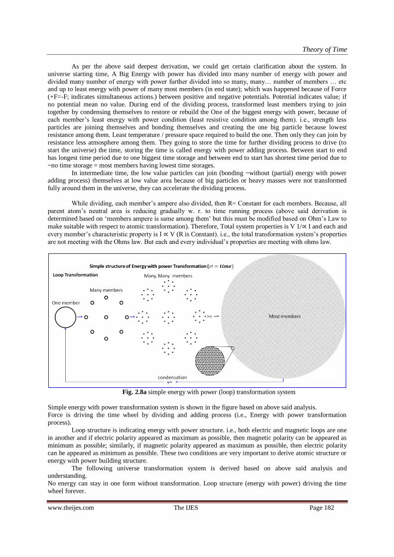
Theory of Time
www.theijes.com The IJES Page 182
As per the above said deepest derivation, we could get certain clarification about the system. In
universe starting time, A Big Energy with power has divided into many number of energy with power and
divided many number of energy with power further divided into so many, many… number of members … etc and up to least energy with power of many most members (in end state); which was happened because of Force
(+F=-F; indicates simultaneous actions.) between positive and negative potentials. Potential indicates value; if
no potential mean no value. During end of the dividing process, transformed least members trying to join
together by condensing themselves to restore or rebuild the One of the biggest energy with power, because of
each member‘s least energy with power condition (least resistive condition among them). i.e., strength less
particles are joining themselves and bonding themselves and creating the one big particle because lowest
resistance among them. Least temperature / pressure space required to build the one. Then only they can join by
resistance less atmosphere among them. They going to store the time for further dividing process to drive (to
start the universe) the time, storing the time is called energy with power adding process. Between start to end
has longest time period due to one biggest time storage and between end to start has shortest time period due to
~no time storage = most members having lowest time storages.
In intermediate time, the low value particles can join (bonding ~without (partial) energy with power adding process) themselves at low value area because of big particles or heavy masses were not transformed
fully around them in the universe, they can accelerate the dividing process.
While dividing, each member‘s ampere also divided, then R= Constant for each members. Because, all
parent atom‘s neutral area is reducing gradually w. r. to time running process (above said derivation is
determined based on ‗members ampere is same among them‘ but this must be modified based on Ohm‘s Law to
make suitable with respect to atomic transformation). Therefore, Total system properties is V 1/∝ I and each and
every member‘s characteristic property is I ∝ V (R is Constant). i.e., the total transformation system‘s properties
are not meeting with the Ohms law. But each and every individual‘s properties are meeting with ohms law.
Fig. 2.8a simple energy with power (loop) transformation system
Simple energy with power transformation system is shown in the figure based on above said analysis.
Force is driving the time wheel by dividing and adding process (i.e., Energy with power transformation
process).
Loop structure is indicating energy with power structure. i.e., both electric and magnetic loops are one
in another and if electric polarity appeared as maximum as possible, then magnetic polarity can be appeared as
minimum as possible; similarly, if magnetic polarity appeared as maximum as possible, then electric polarity
can be appeared as minimum as possible. These two conditions are very important to derive atomic structure or
energy with power building structure.
The following universe transformation system is derived based on above said analysis and understanding.
No energy can stay in one form without transformation. Loop structure (energy with power) driving the time
wheel forever.
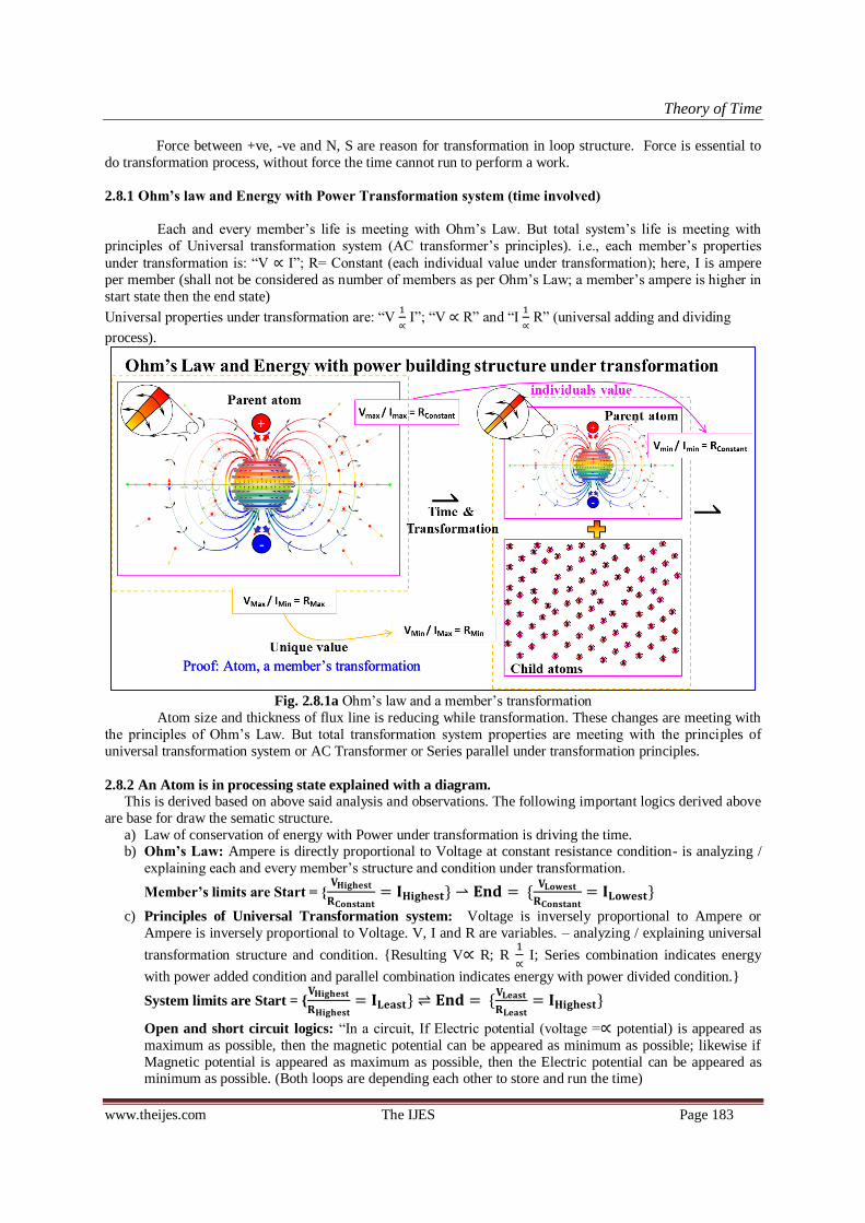
Theory of Time
www.theijes.com The IJES Page 183
Force between +ve, -ve and N, S are reason for transformation in loop structure. Force is essential to
do transformation process, without force the time cannot run to perform a work.
2.8.1 Ohm’s law and Energy with Power Transformation system (time involved)
Each and every member‘s life is meeting with Ohm‘s Law. But total system‘s life is meeting with
principles of Universal transformation system (AC transformer‘s principles). i.e., each member‘s properties
under transformation is: ―V ∝ I‖; R= Constant (each individual value under transformation); here, I is ampere
per member (shall not be considered as number of members as per Ohm‘s Law; a member‘s ampere is higher in
start state then the end state)
Universal properties under transformation are: ―V
∝ I‖; ―V ∝ R‖ and ―I
∝ R‖ (universal adding and dividing
process).
Fig. 2.8.1a Ohm‘s law and a member‘s transformation
Atom size and thickness of flux line is reducing while transformation. These changes are meeting with
the principles of Ohm‘s Law. But total transformation system properties are meeting with the principles of
universal transformation system or AC Transformer or Series parallel under transformation principles.
2.8.2 An Atom is in processing state explained with a diagram. This is derived based on above said analysis and observations. The following important logics derived above
are base for draw the sematic structure.
a) Law of conservation of energy with Power under transformation is driving the time. b) Ohm’s Law: Ampere is directly proportional to Voltage at constant resistance condition- is analyzing /
explaining each and every member‘s structure and condition under transformation.
Member’s limits are Start =
c) Principles of Universal Transformation system: Voltage is inversely proportional to Ampere or
Ampere is inversely proportional to Voltage. V, I and R are variables. – analyzing / explaining universal
transformation structure and condition. Resulting V∝ R; R
∝ I; Series combination indicates energy
with power added condition and parallel combination indicates energy with power divided condition.
System limits are Start =
Open and short circuit logics: ―In a circuit, If Electric potential (voltage =∝ potential) is appeared as
maximum as possible, then the magnetic potential can be appeared as minimum as possible; likewise if
Magnetic potential is appeared as maximum as possible, then the Electric potential can be appeared as minimum as possible. (Both loops are depending each other to store and run the time)
Proof: Atom, a member‘s transformation Proof: Atom, a member‘s transformation

Theory of Time
www.theijes.com The IJES Page 184
d) Newton‘s 3rd law and mirror rule is helping to understand the structure of concurrent potential values &
its relativity. Transformation is happening because of Force, which is driving the time.
e) Loop structure indicates source (time storage) with load (running time); magnetic and electric loops are one in another. One loop‘s time storage is tied by another type of loops.
Fig. 2.8.2a A member‘s processing structure under transformation
Both electric and magnetic loops are relative components / structure of Energy with Power building
structure under transformation. As per the above, Electric loop is having opposite potential building structure
with closed circuit (energy with power structure = time storage with time running structure) and magnetic
loops are have not any time storage but which is generated over the source neutral (time storage) due to
returned electric energy suddenly stopped by repel force of the same pole at source. i.e., the stored time is
running through power as dividing process, after consumption (after energy dividing) at load minimum energy
returned to source due to attraction of the opposite pole‘s members. But in source both +ve and -ve energies are
in stored condition (balanced condition). While returning to source; after attraction process, the minimum
energy crossing the neutral zone and repelled (stopped) by the same pole source. Due to this sudden change in
kinetic energy is generating potential ~less magnetic loops over the source neutral. The generated magnetic loops are squeezing the electric storage by reducing its diameter. Which is helps to build pressure inside the
magnetic bonds and flowing the electric energy. Refer open and short circuits properties for better
understanding.

Theory of Time
www.theijes.com The IJES Page 185
Occupying more space Occupying more space
Contain Divided Individuals Contain Divided Individuals
Independent value
𝐕𝐇𝐢𝐠𝐡
𝐑𝐂𝐨𝐧𝐬𝐭𝐚𝐧𝐭 𝐈𝐇𝐢𝐠𝐡
Independent value
𝐕𝐇𝐢𝐠𝐡
𝐑𝐂𝐨𝐧𝐬𝐭𝐚𝐧𝐭 𝐈𝐇𝐢𝐠𝐡
Independent value
Start = 𝐕𝐇𝐢𝐠𝐡𝐞𝐬𝐭
𝐑𝐂𝐨𝐧𝐬𝐭𝐚𝐧𝐭 𝐈𝐇𝐢𝐠𝐡𝐞𝐬𝐭
Independent value
Start = 𝐕𝐇𝐢𝐠𝐡𝐞𝐬𝐭
𝐑𝐂𝐨𝐧𝐬𝐭𝐚𝐧𝐭 𝐈𝐇𝐢𝐠𝐡𝐞𝐬𝐭
Parent loop Parent loop
Parent Parent
Independent value
𝐕𝐋𝐨𝐰
𝐑𝐂𝐨𝐧𝐬𝐭𝐚𝐧𝐭 𝐈𝐋𝐨𝐰
Independent value
𝐕𝐋𝐨𝐰
𝐑𝐂𝐨𝐧𝐬𝐭𝐚𝐧𝐭 𝐈𝐋𝐨𝐰
Parent Loop Parent Loop
End state = 𝐕𝐋𝐞𝐚𝐬𝐭
𝐑𝐋𝐞𝐚𝐬𝐭 𝐈𝐇𝐢𝐠𝐡𝐞𝐬𝐭 End state =
𝐕𝐋𝐞𝐚𝐬𝐭
𝐑𝐋𝐞𝐚𝐬𝐭 𝐈𝐇𝐢𝐠𝐡𝐞𝐬𝐭
Whole System Value Whole System Value
Pri
nci
ple
s of
Un
ivers
al
Tra
nsf
orm
ati
on
Syst
em
Pri
nci
ple
s of
Un
ivers
al
Tra
nsf
orm
ati
on
Syst
em
Oh
m’s
Law
O
hm
’s L
aw
Independent value
𝐕𝐋𝐞𝐚𝐬𝐭
𝐑𝐂𝐨𝐧𝐬𝐭𝐚𝐧𝐭 𝐈𝐋𝐞𝐚𝐬𝐭
Independent value
𝐕𝐋𝐞𝐚𝐬𝐭
𝐑𝐂𝐨𝐧𝐬𝐭𝐚𝐧𝐭 𝐈𝐋𝐞𝐚𝐬𝐭
Parent Parent
= 𝐕𝐇𝐢𝐠𝐡
𝐑𝐇𝐢𝐠𝐡 𝐈𝐋𝐨𝐰 =
𝐕𝐇𝐢𝐠𝐡
𝐑𝐇𝐢𝐠𝐡 𝐈𝐋𝐨𝐰
Whole System Value Whole System Value
=𝐕
𝐋𝐨𝐰
𝐑𝐋𝐨𝐰 𝐈 𝐇
𝐢𝐠𝐡
=𝐕
𝐋𝐨𝐰
𝐑𝐋𝐨𝐰 𝐈 𝐇
𝐢𝐠𝐡
Wh
ole
Sy
stem
Valu
e
Wh
ole
Sy
stem
Valu
e
A member‘s
Energy = ½ VIt
Power = ½ VI
Life time = ½ VIt/½VI
Start End
= time running
A member‘s
Energy = ½ VIt
Power = ½ VI
Life time = ½ VIt/½VI
Start End
= time running
Total System‘s
Energy = VIt = C
Power = VI = C
Life time = VIt/VI
Start End
= time running
Total System‘s
Energy = VIt = C
Power = VI = C
Life time = VIt/VI
Start End
= time running
Magn
eti
c M
em
ber
Magn
eti
c M
em
ber
S
S N
N
Lea
st A
mp
ere
L
ea
st A
mp
ere
100%
Gravit
y
100%
Gravit
y
Hig
hest
Am
pere
H
igh
est
Am
pere
Condensation Condensation
Electric short circuit Electric short circuit
Ele
ctr
ic M
em
ber
Ele
ctr
ic M
em
ber
Occupying less space
Start state =
Occupying less space
Start state =
Unique Unique Whole System Value Whole System Value
Highest Electric potential Highest Electric potential
A E
lect
ric
mem
ber
‘ s
tran
sform
atio
n
pro
cess
=>
>>
A E
lect
ric
mem
ber
‘ s
tran
sform
atio
n
pro
cess
=>
>>
Liv
e ti
me
run
nin
g p
roce
ss (
loop
) L
ive
tim
e ru
nn
ing p
roce
ss (
loop
)
1/R 1/R
R R
Fig. 2.8.2b Universal Energy with Power Dividing
and adding process 1 of 2
Fig. 2.8.2b Universal Energy with Power Dividing
and adding process 1 of 2
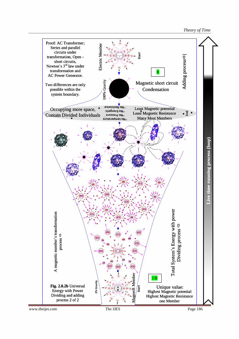
Theory of Time
www.theijes.com The IJES Page 186
Unique value: Unique value:
Liv
e ti
me
run
nin
g p
roce
ss (
loop
) L
ive
tim
e ru
nn
ing p
roce
ss (
loop
)
N
N S
S
Condensation Condensation
Occupying more space,
Contain Divided Individuals
Occupying more space,
Contain Divided Individuals
100%
Gra
vit
y
100%
Gra
vit
y
Mag
net
ic M
ember
M
agn
etic
Mem
ber
Ele
ctri
c M
ember
E
lect
ric
Mem
ber
Tota
l S
yst
em
‘s E
ner
gy w
ith p
ow
er
Div
idin
g p
roce
ss
Tota
l S
yst
em
‘s E
ner
gy w
ith p
ow
er
Div
idin
g p
roce
ss
Add
ing p
roce
ss
| A
dd
ing p
roce
ss
|
Proof: AC Transformer;
Series and parallel circuits under
transformation, Open -
short circuits,
Newton‘s 3rd law under
transformation and
AC Power Generator.
Two differences are only
possible within the
system boundary.
Proof: AC Transformer;
Series and parallel circuits under
transformation, Open -
short circuits,
Newton‘s 3rd law under
transformation and
AC Power Generator.
Two differences are only
possible within the
system boundary.
Magnetic short circuit Magnetic short circuit
Highest Magnetic potential
Highest Magnetic Resistance
one Member
Highest Magnetic potential
Highest Magnetic Resistance
one Member
A m
agn
etic
mem
ber
‘s tra
nsf
orm
atio
n
pro
cess
A m
agn
etic
mem
ber
‘s tra
nsf
orm
atio
n
pro
cess
Least Magnetic potential
Least Magnetic Resistance
Many Most Members
Least Magnetic potential
Least Magnetic Resistance
Many Most Members
R R
1/R 1/R
Fig. 2.8.2b Universal
Energy with Power
Dividing and adding
process 2 of 2
Fig. 2.8.2b Universal
Energy with Power
Dividing and adding
process 2 of 2

Theory of Time
www.theijes.com The IJES Page 187
Principles of Ohm's Law + Universal Transformation System Remarks
Description Symbol Clarification <<=past <=present=> Future=>> Unit
Voltage V Voltage 100 50 25 12.5 Volt
Ampere per member In Ampere/
member
1 0.5 0.25 0.125 Ampere
R per member = C Rn V/In 100 100 100 100 Ω Ohm's Law
Number of members N in numbers 1 4 16 64 in
numbers
Life time per
member
t life time/
member
120 120 120 120 seconds each
members life time
Total Ampere I In * N 1 2 4 8 Ampere
Power / member R V*In 100 25 6.25 1.5625 Ω intensity*
Total Power = VI =
C
P VI 100 100 100 100 Watts
Energy / member En V.In.t 12000 3000 750 187.5 Joule
Total Energy = C E V.In.t * N 12000 12000 12000 12000 Joule
Total R = V/I R V/I 100 25 6.25 1.5625 Ω intensity*
life time/ member t seconds 120 120 120 120 seconds t/member
1/(t/N) X 0.008 0.008 0.008 0.008
X*N XN 0.008 0.033 0.133 0.533
System‘s life time =
ts
1/XN unique time 120 30 7.5 1.875 seconds series to
parallel
ts /R = C R* Constant 1.2 1.2 1.2 1.2 Constant Logic
System‘s life time =
ts
ts = t/N universal
time divided
120 30 7.5 1.875 seconds Logic
Table 2.8.2a Model calculation based on above said combined principles of Ohm‘s law + Universal
Transformation system (systematically balanced transformation system)
Model calculation calculated based on above said principles and found that the linkage traceability has
been established systematically to take prompt decision on system and its transformation process.
Here, Total ampere = I = (Ampere per member * Number of members available inside the system). = In * N
Start state one member‘s life (series) = sum of all individual members life (parallel)
Used Both Ohm‘s law and principles of universal transformation system for calculation as stated
above. Transformation process of Energy with power dividing process is resulting work done (movement, flow,
speed, velocity), but mass cannot get increase because of work done imposed on mass energy. Example in
power generator; speed obtained from mechanical energy is imposed on normal electric potential flow (by increasing temporary magnetic energy storage releasing speed). Power generator is doing the transformation
work of Resulted Work done (speed) forced or included on normal electric potential flow.
Mass is supporting agent for transformation with respect to work done.
Based on the above analysis, heavy particles (number of members low) can deliver higher Work done
while transformation process rather than the work done obtain form transformation of equal mass of light
particles (number of members high).
Resistance to transformation = R = Power /member based on combination principles of Ohms law +
Universal Transformation system. This is correct and actual method and meeting with the system‘s
transformation process. (Ohms law followed)
If we consider ampere of each member is same (considered as ampere is not divided) than R =
(Power/member)/ total members based on AC Transformer or series parallel under transformation principles (Ohms law not followed). This is also giving logical results, but this is not actual or natural condition with
respect to past to future system‘s (universe) transformation conditions. (This is giving more clarity while
relating each other)
Resistance per member is constant throughout the entire life of the system as per ohm‘s law. Resistance
is declaring the life time period. life time is used to do something through power. V/I = R = V(In ); (I = Total
ampere; In = Ampere per member); Total resistance = Power per member. I2 = N and 1/I= In;
In the following diagram, how the transformation happening is shown in both the type of atoms. Child
atoms are created due to force and closed circuit. Source energy is transforming through power like an example
as shown in following.

Theory of Time
www.theijes.com The IJES Page 188
i.e., Energy = ½VIt (time storage) ½VI.t (time running); ex. atom, magnet, battery
System: Electric Transformation Magnetic Transformation
Fig 2.8.2c Energy dividing process (a big potential energies with powers is dividing into more) - Transformation
resulting work done
Fig. 2.8.2d Electric and Magnetic energy with power structure with particles creation
= =
E E
P P
An Example: Energy at source has low members and which is divided through power to run the time. While dividing the number of members are multiplied. However the energy with power is constant. Here, less members of source energy with
power is transformed into many members of source with power at load. The energy with power of a form
is changing to drive time.
Load Load

Theory of Time
www.theijes.com The IJES Page 189
Both electric and magnetic particles are only available in system. But in starting state any one type of
particle only available. One type of particles can deliver another type of particle while joining (bonding) as
quantum of matter (proof: magnet: while bonding, the independent loops are transforming into universal loop by transforming universal loops into independent loops). Bonding of electric atoms in circle /loops shape (short
circuit) can create magnetic potential, at the same time, bonding of magnetic atoms in circle/ loops condition
(short circuit) can create electric potential. Where ever potential is there, there should have Energy with power
transformation. Refer open and closed circuit for more clarification.
Fig. 2.8.2e Electric atom cross sectional views – designed on 2001
Above said atomic structure was designed during the year of 2000-2001, both positive and negative
potential is under transformation because of closed circuit is shown. Both electric and magnetic loops are one in
another. Any one of the loop (magnetic or electric) must have potential because of time storage, due to this other
can get low potential ~= no potential (short circuit). i.e., we can measure both the potentials under
transformation. All the electric loops are joined together inside the atom, and all the magnetic loops are
independent over the electric loop. Refer open and closed circuit for more clarification.
Deep explanation on Universe transformation structure based on atomic structure: Source energy is
transforming through Power under energy dividing process, i.e., one big particle (energy with power) divided
into so many numbers of particles. The divided particles escaping from the source or throw away from the
source, i.e., which is moving away from the source with certain velocity under energy with power dividing
process. High speed Low value particles can penetrate heavy masses if the heavy masses are interrupting the
leaving particles. Then, that action can generates gravity toward the heavy mass.
If the leaving particles have low value (energy with power) then that will not go near the heavy mass
for bonding; after certain travel, the low value particles are moving toward least temperature/ pressure area
(space) inside the universe, because of inability to go near the heavy masses or particles. The leaving particles
are generating gravity while moving as per Newton‘s 3rd law. (Force is directly proportional to power (dividing process))
If the leaving particles are having high value then that can go near the heavy mass and can join with
heavy particles by attraction to form a molecule in solid / liquid / gaseous state at high value areas. Value
indicates potential value or force.
In any closed circuit the power can deliver small, medium and heavy particles at a time due to potential
difference at load. And the size of the particles gradually decreased from high value to low value under
transformation as per energy with power dividing process to drive time from start to end. During that process the
transformed low value particles are leaving from heavy masses and joining themselves at least value area; since
the low value particles cannot do high energetic transaction among them due to low resistance condition. They
can undergo further energy with power divided process due to heavy masses are available around them. They
will not be allowed to do energy with power adding process due to pressure from heavy masses around them.
They appeared as black matter or black energy with power. The low potential particles can deliver least value
Designed on January 2001 Designed on January 2001
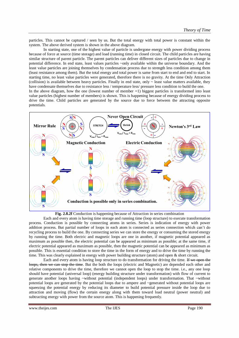
Theory of Time
www.theijes.com The IJES Page 190
particles. This cannot be captured / seen by us. But the total energy with total power is constant within the
system. The above derived system is shown in the above diagram.
In starting state, one of the highest value of particle is undergone energy with power dividing process because of force at source (time storage) and load (running time) in closed circuit. The child particles are having
similar structure of parent particle. The parent particles can deliver different sizes of particles due to change in
potential difference. In end state, least values particles ~only available within the universe boundary. And the
least value particles are joining themselves by condensation process due to strength less condition among them
(least resistance among them). But the total energy and total power is same from start to end and end to start. In
starting time, no least value particles were generated, therefore there is no gravity. At the time Only Attraction
(collision) is available between heavy particles. Finally in end state, only ~ least value matters available, they
have condensate themselves due to resistance less / temperature less/ pressure less condition to build the one.
In the above diagram, how the one (lowest number of member =1) biggest particles is transformed into least
value particles (highest number of members) is shown. This is happening because of energy dividing process to
drive the time. Child particles are generated by the source due to force between the attracting opposite
potentials.
Fig. 2.8.2f Conduction is happening because of Attraction in series combination
Each and every atom is having time storage and running time (loop structure) to execute transformation process. Conduction is possible by connecting atoms in series. Series is indication of energy with power
addition process. But partial number of loops in each atom is connected as series connection which can‘t do
recycling process to build the one. By connecting series we can store the energy or consuming the stored energy
by running the time. Both electric and magnetic loops are one in another, if magnetic potential appeared as
maximum as possible then, the electric potential can be appeared as minimum as possible; at the same time, if
electric potential appeared as maximum as possible, then the magnetic potential can be appeared as minimum as
possible. This is essential condition to store the time in the form of energy and to drive the time by running the
time. This was clearly explained in energy with power building structure (atom) and open & short circuit.
Each and every atom is having loop structure to do transformation for driving the time. If we open the
loops, then we can stop the time. But the both the loops (electric and Magnetic) are depended each other and
relative components to drive the time, therefore we cannot open the loop to stop the time. i.e., any one loop should have potential (universal loop) (energy building structure under transformation) with flow of current to
generate another loops having ~without potential (independent loops) under transformation. That ~without
potential loops are generated by the potential loops due to ampere and ~generated without potential loops are
squeezing the potential energy by reducing its diameter to build potential pressure inside the loop due to
attraction and moving (flow) the certain energy along with them toward load neutral (power neutral) and
subtracting energy with power from the source atom. This is happening frequently.

Theory of Time
www.theijes.com The IJES Page 191
Fig. 2.8.2g Attraction and repel actions (force)
series combination is achieved by attraction process between opposite potential polarities (positive and
negative or North pole and south pole) and helping conduction through the attraction process from high
potential to low potential and acting with unique control.
Parallel combination is achieved by repel process between similar potential polarities (+ve & +ve or –
ve & -ve or N & N or S & S) and they are acting with independent control. Hence, there is no conduction
through them.
Both the magnets are moving during attraction or repel action. Everything (differences and similarities)
is falling within the range of start to end state. Contact area is higher in parallel combination and contact area is lower in series combination.
Therefore these characteristic properties are meeting with the universal energy with power adding and dividing
process under transformation as said above.
Gravity force – Power relation explained below and confirmed that Force ∝ Power:
Fig. 2.8.2h Linkage between Gravity and power under Newton‘s 3rd Law (F∝P)
Proof: Force ∝ Power; Resistance to transformation is directly proportional to Potential;

Theory of Time
www.theijes.com The IJES Page 192
Each and every atom is emitting its energy through power to drive the time. Emitted particles escaping
from the heavy mass and moving towards low value (potential less) area; if the emitted particles are having low
or least value (energy with power) then, that moving action creates gravity towards center of heavy mass. Which can penetrate while escaping. The low or least value (potential energy with power) particles can‘t be captured
and can move with high speed toward least value areas. If the emitted particles are heavy, then that can move
near the heavy masses for bonding / losing it energy as power due to force of attraction and cannot create
gravity toward the heaviest atoms.
Satellite‘s PE is inversely proportional to KE or KE is inversely proportional to PE under
transformation. This was explained clearly as shown in the above diagram. Required / Sufficient kinetic energy
must be available with respect to potential energy for rotating around the planet. If KE increased / decreased
then, that will escape or fall down. While rotating around the planet, the Gravitational torque is acting on
satellite for tilting the satellite on orbit around the planet for rotating around the orbit. Ex. Imagine a satellite is
rotation around the planet without self-rotation. Then we could see same view of satellite from around the planet
like our earth‘s moon light. Earth is also having the same effect, but due to self-rotation, the gravitational torque is merged with self-rotation; which is reducing one self-rotation of earth / year. The following diagram
explaining linkage between Gravity force, Kinetic energy and gravitational torque.
Fig. 2.8.2i Gravitational torque generated by Gravity force and Kinetic Energy
Energy: Total energy = PE = mgh + KE = ½mv2 (external) + ME (internal) = Potential energy + Kinetic
energy + Mass Energy
Mass energy of a member within the life time = ½VIt and Power = ½VI (Ex. a particle)
But, mass energy of transformation system = VIt = C and Power = VI = C forever (Start state End
State). Transformation system is containing parent atom(s) with child atoms (total). Electric Mass energy with
power is having the properties of V, I, R, VIt and VI.
Mechanical PE and KE (due to gravity, external force) both are depending on mass energy with power
(loop structure); but, mass energy is not depending external PE or KE for transformation. PE and KE (external)
are created during mass transformation. And external PE, KE and force can be used to transform mass energy
with power. But the mass cannot get increase because of external PE or KE. Reason, the electric Energy with
power is not varying with respect to combinations (series and parallel) as said above. Mass has internal energy with power (electric and magnetic (electro-magnetic)); ie, mass has energy with power, at the same time, energy
with power has mass. Mass transformation resulting external factors (such as gravity, thrust force, velocity).
A satellite without-self rotation
is rotating around the star is
shown here, Gravitational Force
and velocity is creating
Gravitational torque on satellite and tilt the satellite to align
with the orbital. We could see
same view of satellite from the
star like our moon light.
If any mismatch, then the
satellite will escape from star /
fell down on star.
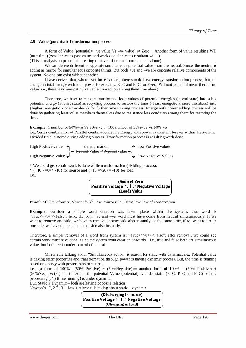
Theory of Time
www.theijes.com The IJES Page 193
2.9 Value (potential) Transformation process
A form of Value (potential= +ve value Vs –ve value) Zero + Another form of value resulting WD
( = time) (zero indicates past value, and work done indicates resultant value)
(This is analysis on process of creating relative difference from the neutral one)
We can derive different or opposite simultaneous potential value from the neutral. Since, the neutral is
acting as mirror for simultaneous opposite things. But both +ve and –ve are opposite relative components of the
system. No one can exist without another.
I have derived that, where ever force is there, there should have energy transformation process; but, no
change in total energy with total power forever. i.e., E=C and P=C for Ever. Without potential mean there is no
value, i.e., there is no energetic / valuable transaction among them (members).
Therefore, we have to convert transformed least values of potential energies (at end state) into a big potential energy (at start state) as recycling process to restore the time least energetic x more members into
highest energetic x one member for further time running process. Energy with power adding process will be
done by gathering least value members themselves due to resistance less condition among them for restoring the
time.
Example: 1 number of 50%+ve Vs 50%-ve 100 number of 50%+ve Vs 50%-ve
i.e., Series combination Parallel combination; since Energy with power is constant forever within the system.
Divided time is stored during adding process. Transformation process is resulting work done.
High Positive value transformation low Positive values
Neutral Value Neutral value
High Negative Value low Negative Values
* We could get certain work is done while transformation (dividing process).
* +10 <=0=> -10 for source and +10 =>20<= -10 for load
i.e.,
Proof: AC Transformer, Newton‘s 3rd Law, mirror rule, Ohms law, law of conservation
Example: consider a simple word creation was taken place within the system; that word is
―True<<<0>>>False‖; here, the both +ve and –ve word must have come from neutral simultaneously. If we want to remove one side, we have to remove another side also instantly; at the same time, if we want to create
one side, we have to create opposite side also instantly.
Therefore, a simple removal of a word from system is: ―True>>>0<<<False‖; after removal, we could see
certain work must have done inside the system from creation onwards. i.e., true and false both are simultaneous
value, but both are in under control of neutral.
Mirror rule talking about ―Simultaneous action‖ is reason for static with dynamic. i.e., Potential value
is having static properties and transformation through power is having dynamic process. But, the time is running
based on energy with power transformation.
i.e., a form of 100%= (50% Positive) + (50%Negative) another form of 100% = (50% Positive) +
(50%Negative) ( = time) i.e., the potential Value (potential) is under static (E=C; P=C and F=C) but the
processing ( ) (time running) is under dynamic.
But, Static x Dynamic – both are having opposite relation
Newton‘s 1st, 2nd , 3rd law + mirror rule taking about static + dynamic.
𝐏𝐨𝐬𝐢𝐭𝐢𝐯𝐞 𝐕𝐨𝐥𝐭𝐚𝐠𝐞 । 𝐍𝐞𝐠𝐚𝐭𝐢𝐯𝐞 𝐕𝐨𝐥𝐭𝐚𝐠𝐞
(Source) Zero
(Load) Value
𝐏𝐨𝐬𝐢𝐭𝐢𝐯𝐞 𝐕𝐨𝐥𝐭𝐚𝐠𝐞 । 𝐍𝐞𝐠𝐚𝐭𝐢𝐯𝐞 𝐕𝐨𝐥𝐭𝐚𝐠𝐞
(Source) Zero
(Load) Value
𝐏𝐨𝐬𝐢𝐭𝐢𝐯𝐞 𝐕𝐨𝐥𝐭𝐚𝐠𝐞 । 𝐍𝐞𝐠𝐚𝐭𝐢𝐯𝐞 𝐕𝐨𝐥𝐭𝐚𝐠𝐞
(Discharging in source)
(Charging in load)
𝐏𝐨𝐬𝐢𝐭𝐢𝐯𝐞 𝐕𝐨𝐥𝐭𝐚𝐠𝐞 । 𝐍𝐞𝐠𝐚𝐭𝐢𝐯𝐞 𝐕𝐨𝐥𝐭𝐚𝐠𝐞
(Discharging in source)
(Charging in load)

Theory of Time
www.theijes.com The IJES Page 194
Concurrent opposite potential energy‘s charging and discharging principles are explained systematically as
above.
2.10 Time (Final Review)
First I have done deep analysis between Series, Parallel combination and AC transformer (electricity
Source with Load combination) based on Law of Conservation of Energy under transformation condition for
identifying characteristic Properties of Electricity under Transformation. I understood that, Resistance is
separating both positive and negative potential from the middle point of neutral in systematic way. i.e.,
resistance is building the potential energy with power from neutral in systematic manner as explained in power
building structure and it is resisting mixing together at source. Its mean keeping positive and negative polarity in
potential, hence, each member itself has ‗resistive voltage‘. R=V/I and the resistance is very important for
declaring the Time duration (life time) of energy with power transformation process from one form into another
form (start to end).
Life time (t) is directly proportional to Resistance, i.e., time is directly proportional to Voltage and
inversely proportional to Ampere. Since, R is directly proportional to Voltage under transformation; so that, the voltage is inversely proportional to ampere ―at the same time‖ the current is inversely proportional to voltage
under transformation.
Resistance: ―The electrical resistance of an electrical element is the opposition to the passage of an electric
current through that element‖ –from Wikipedia
As per 2.1.2 ―R is never constant‖ in transformation process or energy with power dividing and adding
process with in the electricity; we must consider always closed circuit for any (in open circuit, the resistance
value can be considered based on loss due to time). In transformation system, the Resistance value is gradually
reducing during Energy with power dividing process from start to end; the time is running based on
transformation. i.e., Conversion process between the ‗start to end‘ and ‗end to start‘ are driving the time without
start ‗at the same time‘ without stop or ―Start Stop‖; actually we cannot/ could not make any open circuit to stop the time running process; but we can reduce the acceleration of time running process by reducing
consumption rate (reducing transformation speed). Transformation is happening through power. t =VIt/VI
Example:
Fig. 2.10a Lead acid battery in closed and open circuit (time storage and time running)
The atom‘s loops are in closed condition while keeping the conductor in open circuit; in closed circuit,
the atom‘s partial loops are transferred to load through conductor by attraction process for accelerating the time
running speed. i.e., Atom‘s small loops are transforming into bigger loop through conductor‘s atoms by attraction while closing the circuit at load. Closed circuit is indicates energy with power structure. Time storage
from source is flowing through conductor and divided (running) through power.

Theory of Time
www.theijes.com The IJES Page 195
Fig. 2.10b lead acid battery with closed circuit under charging and discharging condition
During charging, the Time storage from one source can be stored into another source by running
(driving) the time through attractive bonding (series combination). Storing can be possible from high potential
to low potential. Higher potential is acting as source and lower potential is acting as load. For storing both +ve
and –ve potential must have move equally from source to load. In closed circuit, both +ve and –ve potential is
moving (running) from source to load and storing the time by attractive force and pressure. During discharging
the higher energies moving opposite to one another and storing the energy at high resistive load and stored
energies are leaving as light rays. The stored particles are throwing away from source due to high pressure (high resistance).
Charging and discharging properties can be analyzed by using capacitor for better understanding as
explained below.
Fig.2.10c Capacitor charging and discharging by running the time
Time storage from battery is storing in capacitor by accelerating speed of normal running time
(resistance is low between the parallel plates (for energy storing in device) compared with resistive load (for
light rays generation); pressure intensity is more in resistive load and lower in capacitor load due to more area).
Similarly, stored time in capacitor is discharging by accelerating speed of normal running time. Discharged
potential energy converted or divided into light rays through high resistive load. The resistive load is reducing the rate of flow and increasing intensity, higher potential resistance with higher pressure is generated due to
attraction between positive and negative potential at load.
Energy with power is subtracted from source due to force at high resistance area and the subtracted
energy with power is escaped/ throws away as light rays.

Theory of Time
www.theijes.com The IJES Page 196
Light rays are child particles having source with load structure. i.e., the energy with power of source is
divided into more number of members under transformation.
Fig. 2.10d polarity direction of Potentials; attraction leads to Series & repletion leads to Parallel
Electricity is flowing through them while connecting in series (attracting activities) and electricity is
not flowing through them while connecting in parallel (repletion activities). in series, the individual loops are
transforming into universal loop because of attraction, which creates electricity flow through them from high
pressure to low pressure and we could see unique control and activities among them; but in parallel, all are
acting individually with their individual control due to repel action among them; therefore no energy flow
through them. In PN diode, P type is having negative potential polarity and N type is having Positive potential
polarity. This was arrived based on comparative study on battery, capacitor and diode. But both the polarities
are opposite to one another.
Fig. 2.10e similarity between Battery, Capacitor and PN Diode.
Electricity is flowing opposite to one another due to attraction. Without attraction the electricity cannot
flow through them; but each and every one (members) is having loop structure with individual control. i.e.,
members in parallel combination are acting individually with their own control due to repel action; therefore the
time is running individually. Then members in series combination are acting with unique control due to
attractive action and their time running process is in unique control. Newton‘s 3rd Law is playing major role in everything. ie, where ever force is there, there should have energy with power transformation. Since Newton‘s
1st and 2nd and 3rd laws are having inter relation under transformation and playing major role in everything.
Time running and transformation is having direct relation. ―No energy will transform within 0 time from one
form into another form; at the same time, the energy cannot remain without transformation with respect to
running of time‖ – Proof: matter; atom, battery, capacitor, magnet, etc.; i.e., the stored energy is never-remain
constant in one form without transformation. Energy transformation is running the time or due running of time;
the energy is transforming from one form into another form. Therefore the time running process is ever running
process under transformation. i.e., the source energy is reducing during passing of each and every second and
the reduced energy is converted or divided into so many no. of energies through load as power.
The resistance value for open circuit can be calculated based on loss due to time and can be considered
as resistance value for open circuit. i.e., Closed circuit also indicates that the resistance in-between the open

Theory of Time
www.theijes.com The IJES Page 197
circuit. The resistance value is deciding the time period of the energy with power conversion process from start
to end. V ∝ R, I
∝ R and I
∝ V under transformation; which is causing that, the time running is ever running
Process.
Energy Transformation is happening from one form into another form through Power- this is indicates
―Never open circuit‖ within the system -The time is ever running process without any interruption (stop or
start). The open circuit is not indicates that, the time is not running; do not consider like ―the time is not running
in open circuit‖; the resistance value can be calculated for open circuit based on loss due to time.
The system is changing itself as energy with power dividing process and adding process to drive the
time. That indicates time is running without stop ‗at the same time‘ without start or ―Start Stop‖
Therefore we must consider resistance in between open circuit. i.e., Members of Each and every energy
with power is converting itself as dividing itself into so many numbers of energies with powers due to loop
structure to drive the time, even If we store the energy and keep it in open circuit. (Proof: Generator with open
circuit, Tesla coil, Transformer, battery, magnet etc.)
All and everyone are showing as different as per our perspective. How we are perusing? It is very
important. We can bring all the differences under the common one using systematic approach to make
clarification with 100%. A common one can show so many different with respect to each one‘s perception and
we are making so many different from a common one. This time theory derived based on universal conversion
process or transformation process. By using this, we can bring everything under the common one.
Importance of Ohm’s Law: while dividing and adding process, each and every member‘s source (½VIt) with
Load (½VI) is independently transforming as shown below with respect to running of time.
Member’s limits are Start =
=> Ohm‘s law is analyzing
each member‘s properties under transformation and meeting with law or principles of universal transformation
system.
Total System limits are Start =
=> principles of Universal
Transformation system is analyzing total system properties under transformation. this is having principles of AC
Transformer; Law of conservation of Energy, power, mass and momentum; Series parallel combination under
transformation;
Above said Series and parallel under transformation derivation is suitable for all the applications.
Always we are using Transformer for all the applications. Therefore Series, parallel principles are equal to AC Transformer principles; Hence, Ohm‘s law failed to meet the requirement of AC Transformer. But ohm‘s law is
meeting with each and every individuals transformation properties. Note: This is actual condition and we are
using this concept regularly in all the applications. Example Capacitor, Diode, resistors etc. are designed based
on the Voltage rating as well as Current rating. The resistance value per member could/ should be increased
based on increase in Voltage rating (V∝R) under transformation.
Fig. 2.10f Bonding of Atoms in loop shape can create potential in another loop
In the above said diagram, bonding of electric atoms in loop shape can generate potential in magnetic loop is
shown. Refer open and short circuit for more clarification.
Example: electric short circuit loops are over the magnetic universal loop(s) as explained below

Theory of Time
www.theijes.com The IJES Page 198
Fig. 2.10g Magnetic structure: Electric Short circuit loops over the magnetic potential loop(s)
In the above diagram, magnetic structure updated based on analysis done above. Any circuit must have
both the loops and the loops are once in another. One loop must have time storage in the form of potential and
another loops cannot get potential and indicates short circuits.
i.e., the magnetic potential energy is tied by electric potential less loops. Both the loops are dependent
each other for transformation process. Tied time is running through power as live time running process to
execute the transformation system. Transformation process is driving the time.
Attractive force is directly proportional to Power (transformation). And Newton‘s 3rd law is playing
major role in transformation.
Transformation system can survive for ever without fail under transformation (series parallel) . i.e., <<<= Infinite past <<<=Present=>>> Infinite future=>>>
2.11 Space and Time (matter’s transformation only)
Space (universe) contains matter (contain energy with power particles) and non-matter space. Non-
matter space occupied with matter and the matter can deform, but the non-matter space cannot deform.
Therefore, the matter and time is depending on energy with power transformation. Energy (time storage) and
power (running time) both must be available in system to drive the time.
Fig.2.11a Energy flow rate under transformation – AC Transformer principles
Velocity is higher in series combination and velocity is lower in parallel combination. This is
maintaining normal process inside the system. i.e., Energy and power both are constant forever within the
transformation system to drive the time without start ‗at the same time‘ without stop.
Energy with power has mass and mass has energy with power; there is no change in mass with respect
to combination said above. Therefore mass = constant. The mass cannot get increase or decrease due to increase/ decrease in external (resultant) KE or PE or external force and meeting with the universal transformation
system. i.e., in Theory of Relativity, the mass can get increase due to increase in resultant KE or PE. This is not
possible as per universal transformation system‘s principles. External or resultant KE and PE (due to
gravitational force, external force, due to burning, etc.) is depending on mass energy with power; but mass
energy with power is not depending on external KE and PE for transformation process. But, these (external) can
be used to transform the mass energy with power from one form into another form and can be used to
accelerating the transformation process. Availability of Parallel universes in our system is possible. Since, there
is no boundary for our space and time.
As per newton‘s 3ed law: ―Any action there should have opposite reaction" (both are opposite to one another
and mirror to one another)

Theory of Time
www.theijes.com The IJES Page 199
Our universe has ―matter‖ + ―space without matter‖
Above, I have shown two different things in our space or universe; one is ‗matter‘ another one is ‗space
without matter‘. We can not create more than 2 different with respect to system‘s neutral consideration. Matter has energy, at the same time, energy has matter. – Enstion; therefore, energy with power consist
acceleration, velocity, mass etc. But space without matter has not consist anything. i.e., matter is in the form of
dynamic (always changing) and ‗space without matter‘ is in the form of static. i.e., the ‗matter‘ is plaing inside
the ‗space without matter‘. But both are opposite relative components of the system. and based on the natural
system‘s principel ―one side value must be opposite to another side value‖ in systematic way to do
transformation or to drive the time.
2.12 Conservation Vs Destruction under transformation
System: system means transformation process of energy with power from one form into another form is
causing running of time. Energy with power conversion process is making loss to the current condition. The
time is always running without fail, this is happening because of energy with power conversion process; we
could not conserve energy with power in one form without energy with power transformation; in every passing second the loss is there in the form of energy with power dividing process with respect to start form or previous
form. (Loss due to time means energy dividing process from the past form.) And the conversions are energy
with power dividing and adding process. i.e., one number of energy with power divided into so many number of
energy with power and these so many number of energy with power further converted in to so many many...
and so many many ... up to highest number of least energy with power (near to zero voltage); Finally these all
are converted into one biggest energy with power is called as recycling process. (Electric transformation
Magnetic transformation)
After transformation of one form in to another form, the initial form is attained ZERO (past) + present
form and the transformation process is resulting Work done. We can talk about ZERO for past tense activities.
Newton 3rd law is telling about Force Vs Anti Force and all are happening based on action reaction for driving the time wheel. Without force the time cannot run.
t= VIt/VI; under energy with power (time storage with running time) conversion process; VIt= Constant at the
same time VI= Constant forever. Hence the time is running so ever under energy with power transformation
process.
Logic: Creation x Destruction; both are depend each other. Even we cannot create a single word without
opposite word.
3. CONCLUSION Above said theory was derived systematically to meet with system of nature using combination principles of
Law of conservation of Energy with Power; principles of AC transformer = principles of series parallel
circuits under transformation; Ohms law and Newton‘s Laws.
Ampere (I) can be considered as number of members available in system under universal transformation system. Energy transformation*is required to do something. Energy transformation (power) is directly proportional to
Force or power is directly proportional to ‗change in pressure / change in time‘. Force is required to do
transformation process.
Wherever energy (time storage) is there, there should have energy transformation through power (running time).
None of the energy can stay in one form without transformation with respect to running of time. Since, the time
is running based on energy with power (loop) transformation, ‗at the same time‘, Energy with power (loop) is
transforming because of time running process. Both are having direct relation to drive the time in the form of
time storing and time running.
i.e., Energy with power transformation process between the two forms is
.
(Two differences only possible within the system) (Least ampere indicates Electric potential and highest ampere
indicates Magnetic Potential.)
i.e., transformation system: … Resulted
= ILeast (
=IHighest + Resulting
=
MembersLeast) (
= MembersHighest + Resulting
= ILeast …)
𝐏𝐨𝐬𝐢𝐭𝐢𝐯𝐞 𝐏𝐨𝐭𝐞𝐧𝐭𝐢𝐚𝐥 । 𝐍𝐞𝐠𝐚𝐭𝐢𝐯𝐞 𝐏𝐨𝐭𝐞𝐧𝐭𝐢𝐚𝐥 Create (potential Value)
Destroy (Zero) + potential values +WD
𝐏𝐨𝐬𝐢𝐭𝐢𝐯𝐞 𝐏𝐨𝐭𝐞𝐧𝐭𝐢𝐚𝐥 । 𝐍𝐞𝐠𝐚𝐭𝐢𝐯𝐞 𝐏𝐨𝐭𝐞𝐧𝐭𝐢𝐚𝐥 Create (potential Value)
Destroy (Zero) + potential values +WD
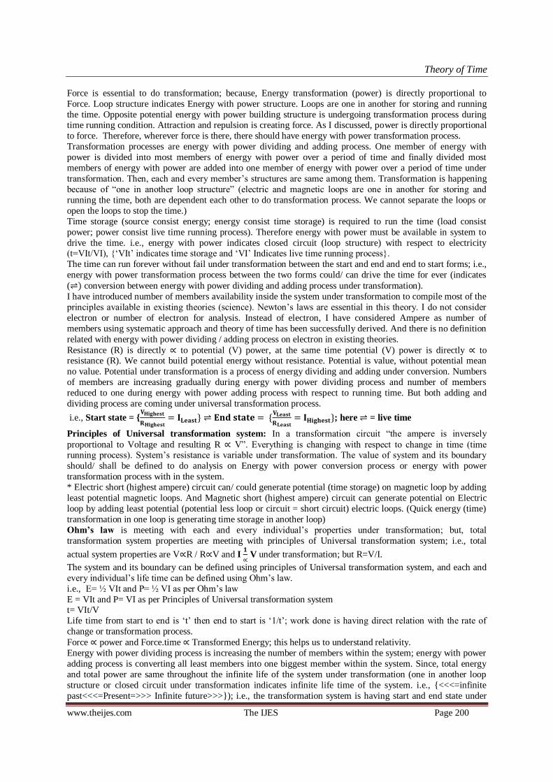
Theory of Time
www.theijes.com The IJES Page 200
Force is essential to do transformation; because, Energy transformation (power) is directly proportional to
Force. Loop structure indicates Energy with power structure. Loops are one in another for storing and running
the time. Opposite potential energy with power building structure is undergoing transformation process during time running condition. Attraction and repulsion is creating force. As I discussed, power is directly proportional
to force. Therefore, wherever force is there, there should have energy with power transformation process.
Transformation processes are energy with power dividing and adding process. One member of energy with
power is divided into most members of energy with power over a period of time and finally divided most
members of energy with power are added into one member of energy with power over a period of time under
transformation. Then, each and every member‘s structures are same among them. Transformation is happening
because of ―one in another loop structure‖ (electric and magnetic loops are one in another for storing and
running the time, both are dependent each other to do transformation process. We cannot separate the loops or
open the loops to stop the time.)
Time storage (source consist energy; energy consist time storage) is required to run the time (load consist
power; power consist live time running process). Therefore energy with power must be available in system to
drive the time. i.e., energy with power indicates closed circuit (loop structure) with respect to electricity (t=VIt/VI), ‗VIt‘ indicates time storage and ‗VI‘ Indicates live time running process.
The time can run forever without fail under transformation between the start and end and end to start forms; i.e.,
energy with power transformation process between the two forms could/ can drive the time for ever (indicates
( ) conversion between energy with power dividing and adding process under transformation).
I have introduced number of members availability inside the system under transformation to compile most of the
principles available in existing theories (science). Newton‘s laws are essential in this theory. I do not consider
electron or number of electron for analysis. Instead of electron, I have considered Ampere as number of
members using systematic approach and theory of time has been successfully derived. And there is no definition
related with energy with power dividing / adding process on electron in existing theories.
Resistance (R) is directly ∝ to potential (V) power, at the same time potential (V) power is directly ∝ to resistance (R). We cannot build potential energy without resistance. Potential is value, without potential mean
no value. Potential under transformation is a process of energy dividing and adding under conversion. Numbers
of members are increasing gradually during energy with power dividing process and number of members
reduced to one during energy with power adding process with respect to running time. But both adding and
dividing process are coming under universal transformation process.
i.e., Start state =
; here = live time
Principles of Universal transformation system: In a transformation circuit ―the ampere is inversely
proportional to Voltage and resulting R ∝ V‖. Everything is changing with respect to change in time (time running process). System‘s resistance is variable under transformation. The value of system and its boundary
should/ shall be defined to do analysis on Energy with power conversion process or energy with power
transformation process with in the system.
* Electric short (highest ampere) circuit can/ could generate potential (time storage) on magnetic loop by adding
least potential magnetic loops. And Magnetic short (highest ampere) circuit can generate potential on Electric
loop by adding least potential (potential less loop or circuit = short circuit) electric loops. (Quick energy (time)
transformation in one loop is generating time storage in another loop)
Ohm’s law is meeting with each and every individual‘s properties under transformation; but, total
transformation system properties are meeting with principles of Universal transformation system; i.e., total
actual system properties are V∝R / R∝V and I
∝ V under transformation; but R=V/I.
The system and its boundary can be defined using principles of Universal transformation system, and each and
every individual‘s life time can be defined using Ohm‘s law.
i.e., E= ½ VIt and P= ½ VI as per Ohm‘s law
E = VIt and P= VI as per Principles of Universal transformation system t= VIt/V
Life time from start to end is ‗t‘ then end to start is ‗1/t‘; work done is having direct relation with the rate of
change or transformation process.
Force ∝ power and Force.time ∝ Transformed Energy; this helps us to understand relativity.
Energy with power dividing process is increasing the number of members within the system; energy with power
adding process is converting all least members into one biggest member within the system. Since, total energy
and total power are same throughout the infinite life of the system under transformation (one in another loop
structure or closed circuit under transformation indicates infinite life time of the system. i.e., <<<=infinite
past<<<=Present=>>> Infinite future>>>); i.e., the transformation system is having start and end state under

Theory of Time
www.theijes.com The IJES Page 201
transformation Start End or No start and no end. We cannot go to past life; but similar past will come in
future as future after recycling (restoring) process.
All the activities inside the system are having direct and indirect relation between them based on Newton‘s laws (base) . i.e., potential value is having both simultaneous positive and negative potential. Big Potential value will
be transformed into low potential values which resulting work done; present and future actions and reactions
were controlled by past action to make balance and to drive the time relatively. Since, the total energy with total
power is constant forever. Based on consumption (transformation) rate, the running time can be accelerated.
I have used principles available in existing theories (science) in systematic way to derive this theory. What i
derived all were taken from current science; I did systematic approach to understand the system of nature. This
is system‘s theory. I have interpreted that, the speech of system of nature into easy understandable manner. Here
I have derived this theory from series, parallel circuits under transformation and AC Transformer; we could/ can
compare this with universe‘s energy with power transformation.
System is in processing state: The one of the Big energy with power is converted into so many no. of energies with Powers, these so many number of energies with powers further converted in to so many most no. of
energies with powers and these so many ... etc up to as much as possible (up to least value to reduce resistance
less condition among them to build the one by condensation). Finally the least value of energies with power
converted in to the Biggest one energy with power (This is called recycling process Like water cycle process.)
So that energy with power is constant throughout the entire infinite life of the system. (The energy with power is
constant forever.) i.e., (Energy storage is indicating time storage => stored Energy is releasing through Power
(power is indicating time running process) => transformed energy with power escaping from heavy mass or
matter to less pressure / temperature area due to less or least value (which leads to gravity generating process)
=> gathering all the low value particles at least pressure / temperature area and showing as black appearance
(black matter or energy with power => finally all heavy masses transformed into least value particles and
occupying more space of universe => condensation process (Gathering all least value particles and convert themselves into the one biggest particle due to least resistance among them or strength less each and every
member‘s condition.
i.e., process of ―Strength less or energy less each and every member gathered and convert themselves into a big
one‖; So that, the system‘s life time will be restored back after destruction to run the time again.
So that, the system has No Start ―at the same time‖ No end, or the system life has ―Start End‖
i.e., ―the system‘s life has start ‗at the same time‘ End under conversion or transformation process‖.<<<Both
+ve and –ve answers are meeting within the system>>>
All the differences were converted from the one; hence we could/ can convert all the differences in to one. All
the changes are happening for driving the time. For that, time storage and running time both are essential. The
present reactions are happening based on past action; same way the future will be based on present and past.
If we consider start state as creation state and end state can be considered as destruction state of current universe; then, the time is running toward destruction state. But Energy with power is constant forever.
Transformation or running of time is loss to the start state or current state. Please conserve natural resources for
our future generations. Consumption rate is accelerating energy with power dividing process. That will
accelerate time running speed.
Finally the transformation system is surviving forever without fail. For that everything is changing itself to drive
the time.
Life Time: More Consumption (transformation) rate is accelerating the time running speed. Energy with power
dividing process is accelerating the time running speed while doing more recycling process / more consumption/
burning/ etc., higher life products cannot be accelerated toward end state quickly. Conserve natural resources
with minimum transformation, which can increase life span of our earth. More transformation / more recycling
processes are accelerating the energy with power dividing process. This will spoil our future generation life.
Therefore, train them for saving (with low acceleration) natural resources to increase life span of earth. Resistance is very important to build the time period under transformation from start to end. i.e., resistance is
keeping the energy in potential (energy building structure under transformation is energy with power building
structure.) and transforming them into another form through power. The power is also having resistance to
control transformation speed. Therefore, the total value of resistance is indication of life span of the
transformation system.
i.e., life time is directly proportional to Resistance. t ∝ R=
; ie., time is directly proportional to Voltage and
inversely proportional to Ampere. And also time is directly proportional capacitance, capacitance is indicates
stored time. therefore, time=t = RC; consider, the time period from start to end is t; then end to start is
.

Theory of Time
www.theijes.com The IJES Page 202
= = =
Fig. 3a Energy with power under transformation process (electricity = atomic = mechanical principles)
In loop structure, energy in source (+ve and –ve potential with systematic arrangement (energy building
structure under transformation is called energy with Power building structure and indicates loop structure) is
flowing to load and subtracted from the source due to force and attraction (acting at load neutral area). The
subtracted energy with power (loop) is moving away from the source.
Principles of Atom, electro-magnetic circuits, AC transformer, mechanical transformation system etc., are
having similar natural properties. Electric and magnetic loops are one in another and depend each other for
transformation. Polarities are opposite to one another and mirror to one another.
Time storage and releasing processes are driving the time.
Resistance is controlling the flow speed. But which is not stopping the energy flowing process (never open
circuit). No resistance mean no life time. Hence, Ohms law is playing major role to maintain resistance in each and every members (R=C).
Member’s limits are Start =
Attraction process is increasing resistance in series combination and repel process is reducing
resistance value in parallel combination. Hence we could take series has one member and parallel has many
members. And this is meeting with the natural principles. Both of +ve and –ve potential is built with systematic
way; potential is Built from neutral by tying the energy with magnetic individual loops under transformation
(time storage with running time indicates loop structure). All the differences in existing science is laying within
the start to end state and each and every member (particle) can show the polarities of +ve and –ve or North and
south pole or combination of +ve, -ve, North pole and south pole. A common thing can/could show so many
differences as much as possible to drive the time during energy with power dividing process due to increase in number of members with respect to time. More consumption (transformation) rate of natural resources can
acceleration the time. This will affect our future generation life by reacting past / present actions. I have
successfully translated that, the speech of nature into known language. Please try to understand that, the created
each and everything was come from ―The One‖ and each and everything transforming itself to drive the time.
Time storage with running time is executing the system without start, at the same time, without stop or
“Start End”.
Mass energy with power
is constant forever. but, work done
due to transformation is considered as external or resulted energy. external or resulted energy with power is
depending on mass, but mass energy with power transformation is not depending on External energy with power and the external energy with power can be imposed with mass energy with power transformation process.
hence, mass cannot get increase due to increase in external energy with power (work done). work done is
performed by mass energy with power transformation process.
* Transformation process is happening through power; therefore, transformation resulting work done. (Time
storing and releasing)
* Electric and magnetic loops are one in another. One type of loops are tying the energy on another loop in
systematic way. Tied energy is releasing through resistance to drive the time. Both the loops are depended each
other for transformation. Transformations are two types one is dividing process and another one is adding
process. Number of members (ampere) are increasing gradually during dividing process. which is increasing
ampere. High ampere is resulting generation of magnetic potential. i.e., one end is talking about electric
member‘s transformation process and other end is talking about magnetic member‘s transformation process. * Equivalent mechanical Resistance to Transformation was successfully calculated based on Resistance to
transformation of Electricity. And both electricity and mechanical principles equaled and identified relational
properties between them.
Mechanical Resistance to transformation = Rmech. = ((Δ Energy/Δ time) / Member)/Total number of
members (Ohm’s law not considered)
i.e., Rmech. = Power per member/ Total number of members.
E E
P P

Theory of Time
www.theijes.com The IJES Page 203
R = Power per member = V.In (based on Ohms law + Universal Transformation system)
(Transformations System’s actual value) ref: Table 2.8.2a
Loss due to collision of even masses: loss was considered as power (during collision energy with power
transformation is happening; i.e., transformation is resulting work done) and found that +P=-P ∝ +F=-F ∝=
-∆p= +∆p (power is directly proportional to Force)
Loss due to collision of uneven masses: P1/m2 = P2/m1 and also found power is not directly proportional to
Force; but confirmed that, the force is required to do transformation. ―Where ever force is there, there should
have Energy with power transformation process‖.
Open Circuit: open circuit cannot be considered as 100% open circuit. Resistance between the open circuits
can be calculated based on loss due to time. Therefore, never open circuit in system of energy with power
transformation.
Ohm‘s law is containing partial principles of system and not meeting itself with Law of Conservation of energy. Ohm‘s law shall/ could be modified using Law of Conservation of energy. Series, parallel
combination of electricity under transformation principles are equal to the principles of AC transformers. *
Ohms law is not suitable for dealing series and parallel circuit principles under transformation. Ampere of a (or
each) member is not divided in series parallel circuits (electric circuit) transformation. Here number of members
consideration is playing major role and AC transformer‘s principles are playing in conversion between series
and parallel of electric circuits. (As per ohms law total ampere is reduced or increased with respect to voltage
and doing regulating activities; not increasing or decreasing ampere per member or each member) Ohms law is
merged with each and every member properties from start to end time period (ampere of each and every
member is divided). Reminder: Above theory from page 4 to 51 is derived using series parallel under
transformation principles (AC Transformer‘s principles) not Ohm‘s law.
All the particles are electro-magnetic system. Electro-magnetic transformation (power) process is resulting Gravity. All Particles are emitting its stored energy (½VIt) by dividing process through power at load;
if the divided members (emitting) are having least value (least potential particles) during energy with power
dividing process, then that will generate gravity force toward center of the mass. i.e., Power and force are having
direct relation. i.e., Force is directly proportional to Power (energy with power transformation).
Resultant work done (speed or velocity) can be used to transform mass energy with power from one
form into another form. In power generator least mass (magnetic and electric) with maximum flow speed
involved to generate power. i.e., work done due to mass transformation (example: water dam) is having velocity
or speed energy. Which is imposed on external masses and it is considered as external factor or resultant factor.
Same way these external velocity energy can be imposed on internal mass energy (Power generator: speed or
velocity from mechanical transformation process is imposed on normal magnetic energy flow speed (Power) by
transformation (quick storing and quick releasing process), which resulting electric power.); i.e., external mass
value is not imposed). Energy transformation under Newton’s 3rd Law: Both +ve and –ve potential energies are opposite to one
another and mirror to one another; -ve energy is having equivalent energy with respect to +ve energy. Negative
energy cannot be considered as nothing or vacuum.
Particle: single particle structure is having both the loops (electric and magnetic) and both are one in another;
both are depended each other for transformation. One loop must have potential time storage; other loops are
independent loops (short circuit loops) over the time stored loop(s).
mass: mass is constant forever; mass cannot get increase because of external or resultant energy. Resultant
energy (work done or KE) due to mass or energy transformation is imposed on external masses; (It can be taken
as speed or velocity energy or PE, here mass is supporting agent. Gravity force generation is zero during start
state and it is 100% during end state (because, energy transformation happening through power; if emitted
particles are low ~ least value, then they can generate gravity toward center of the mass while escaping.). Energy adding and dividing process are life time dividing and adding processes. Transformations are
happening through power as live time running process. Life time of start to end (Dividing) is ‗t‘ years; then end
to start (Adding) is ‗1/t‘ years. Quick energy transformation in one loop is generating potential (time storage) in
another loop.
Mass – Energy Equation: A big particle can deliver more work done rather than the equivalent amount or
equal quantum (mass) of small particles under dividing process. Refer energy with power building structure
under transformation or energy with power balanced Newton‘s 3rd Law under Transformation for further
clarification.

Theory of Time
www.theijes.com The IJES Page 204
I could not found any controversy between the above derived combination principles. Life time is not
reduced or increased when the energy in without transformation condition (without time running condition).
Increasing Consumption rate is acceleration the time running (power) speed and reducing life time of the system. Consuming more than the essential is offence. Which is affecting our future generation life and our
actions will be reacted.
Consumption of natural resources: Work is resultant factor and performed because of mass transformation
process under dividing process in transformation system, example as explained below, lower speed from heavy
mass (momentum = p1) is transferred to trivial mass and getting higher speed as per conservation of
momentum. Similarly these speed is transferred to electric normal flow trivial mass through transformation
process. The mass is not transferred from one to another. Resultant factor from mass transformation process is
transferred from one to another. Mass cannot be created. If no force mean no transformation, without force the
transformation can be happen (no change in energy). That is, the force is not affecting the energy to transform;
life time is not utilized to do something. Transformation (Power) is required to do something.
Fig. 3b Momentum transformation based on conservation of momentum and Comparison statement
Power (transformation process) is energy dividing process to perform a work. Energy dividing process
is resulting work done to perform a work. Consuming work (resultant from mass transformation like burning,
recycling, eating, wasting, transforming, etc… ) more than the needs is wasted one. This will affect our future
life of the system. Keeping resources with low transformation can / could save life of the system with low
acceleration of time. Consuming more than the essential is offence with respect to future generation life. i.e., it is mean that, we are eating future generation‘s life (our children‘s life). Please train our children to save our
natural resources by consuming as minimum as possible. Even if we consume more than the essential or
required level (individuals acts with their own control), the universal transformation system will do its own
control as per rules. The total transformation system‘s resistance value reducing gradually and moving towards
zero for restoring the divided time into ‗the one‘, if we consume more, the universal system‘s resistance value
reducing rate can be accelerated.
* Work Done (external or resultant factor) is performed by mass transformation (internal or mass energy with
power) process as energy with power dividing process. Electric Power Generator is a ~Work Done Transformer
(mass is not created or transferred): least electric mass ~=no mass with highest velocity (from work done) is
involved in electric power generator. Resultant speed is imposed on normal electric flow (normal time running
speed).
Please do reverse analysis and engineering for better understanding and interpretation. Time running process is consuming the life time of the system through transformation. Transformation system is meant for
time running process (time running process is resulting work done) for ever (<<infinite past<< Present>>
infinite future>>. The time running transformation system (energy with power transformation system) shall
survive for ever without fail. Do not worry about the system‘s processes; worry how to save our natural
resources and plan accordingly.
ACKNOWLEDGMENT I would like to thanks to everyone who supported for successful completion of this paper. I learned lots from
nature and which supports me to searching unknown principles and I did up to my knowledge.
Description Big gear
wheel
Small gear
wheel
Speed (N) Low High
Torque (T) High Low
Mass (m) High Low
Momentum (p) Same Same
Energy (E) Same Same
Power (P) Same Same
Theory of Time
www.theijes.com The IJES Page 205
REFERENCES [1] http://en.wikipedia.org/wiki/Ohm%27s_law#cite_note-1
[2] http://en.wikipedia.org/wiki/Series_and_parallel_circuits
[3] http://en.wikipedia.org/wiki/Conservation_of_energy#cite_note-2
[4] http://en.wikipedia.org/wiki/Transformer
[5] http://en.wikibooks.org/wiki/Battery_Power/Lithium_Ion_Batteries
[6] John Bird, Electrical Circuit Theory and Technology, Revised second edition, Chapter 1.5
[7] http://en.wikipedia.org/wiki/Power_%28physics%29
[8] http://en.wikipedia.org/wiki/Capacitor
[9] http://en.wikipedia.org/wiki/Electric_potential_energy
[10] http://en.wikipedia.org/wiki/Electric_field
[11] http://en.wikipedia.org/wiki/Magnetic_field [12] http://science.howstuffworks.com/electromagnet2.htm
[13] http://en.wikipedia.org/wiki/Newton%27s_laws_of_motion
[14] www.algodoo.com
[15] http://en.wikipedia.org/wiki/Electric_current
BIBLIOGRAPHY Donald G. Fink, H. Wayne Beaty, Standard Handbook of Electrical Engineering, 15th edition, ISBN / ASIN:
0071441468 K.
S. Ponnusamy Asst. Professor of Physics, Physics Text Book Higher Secondary First year Volume 1 and Volume
2, Tamilnadu Textbook Corporation, revised edition 2007. © Government of Tamilnadu.
S. Ponnusamy Asst. Professor of Physics, Physics Text Book Higher Secondary Second year Volume 1 and
Volume 2, Tamilnadu Textbook Corporation, revised edition 2007. © Government of Tamilnadu.
Albert Einstein, The Special and General Theory of Relativity, Written on 1916, Source is The Special and
General Theory of Relativity © 1920, Publisher is Methuen & Co Ltd, 1916, Translated by Robert W. Lawson
Richard G. Carter, Electromagnetism for Electronic Engineers, 1st edition, ISBN 978-87-7681-465-6, 26 -98.
K. Ramkumar (myself), Theory of Time, Unpublished book © 2014 http://en.wikipedia.org/wiki/Atomic_theory
http://tedkinsman.photoshelter.com/image/I00006XFN4kNWLYM
http://en.wikipedia.org/wiki/Short_circuit
http://en.wikipedia.org/wiki/Ground_and_neutral
http://en.wikipedia.org/wiki/Electric_power
http://en.wikipedia.org/wiki/List_of_physical_quantities
Biographies and Photographs
My name is Ramkumar, basically Mechanical Engineer. I wanted to know the reason for changes
during my childhood life particularly ageing. I start with searching natural principles around us. It takes 15 years
to complete this theory. Meanwhile I stopped searching process many times due to inability to continue deep
analysis. After a period of time I decided to simplify inter relational principles to do deep analysis and I have
succeeded. This theory will help us to take prompt decision on our future plans.
Please do reverse analysis for better understanding. We must know about
our past and future conditions to make plan accordingly. I am welcoming
comments/ suggestions on this thesis to evolve further.
Thanks,
Ramkumar K
S/o M. Krishnan, Door No. 1/84, Vinayaker koil street, Anuppur Post,
Salem Dt., Tamil Nadu, India, Pin 636139.
E mail: [email protected]

Theory of Time
www.theijes.com The IJES Page 206
ABBREVIATIONS V = Voltage
I = Ampere
R = Resistance
Vs = Versus
PE = Potential Energy
KE = Kinetic Energy
p = pressure, momentum
F = Force
a = acceleration
Vmax =Maximum Voltage
Rmax =Maximum Resistance Imax = Maximum Ampere
Vmin =Minimum Voltage
Rmin = Minimum Resistance
Imin = Minimum Ampere
∝ = Proportional
t = life time
AC = Alternate current
= Transformation or conversion process, live time running process
h = head or height
E = Energy P = Power
m = mass
g = acceleration due to gravity
ṁ = mass flow rate
v = Velocity
C = Capacitance, Constant
NP = Primary number of turns
NS = secondary number of turns
Ahr = Amps hour
ru = Universal Variable Constant
S = Switch
3D = 3 Dimensional A = Area
∂, Δ = delta = Change in
ρ = Density
N = Newton, North Pole
J = Force.time = Impulse
+ve = Positive
-ve = Negative
S = South Pole
Internal KE and PE = Atomic / electric / magnetic Energy (within loops or circuits)
External or resultant KE and PE = Resultant from mass transformation (mass supporting energy), energy due to
Gravity, rocket, due to external force, etc.
……………………………………………………………………………………………………………………...
Rmech. = Mechanical resistance to transformation
RΩ = Electric Resistance to transformation
Ex. = Example
In = Ampere per member
R* = System‘s ―t∝R‖ constant
etc. = etcetera
i.e., = that is,
Rmech. = Mechanical resistance to transformation
RΩ = Electric Resistance to transformation
Ex. = Example
In = Ampere per member
R* = System‘s ―t∝R‖ constant
etc. = etcetera
i.e., = that is,