Theory of Metal Cutting-mechanics of Metal Cutting
18
LECTURE-09 THEORY OF METAL CUTTING - Mechanics of Metal Cutting NIKHIL R. DHAR, Ph. D. DEPARTMENT OF INDUSTRIAL & PRODUCTION ENGINEERING BUET P x P y P z
-
Upload
rizwanul-fattah -
Category
Documents
-
view
9.818 -
download
38
description
Theory of Metal Cutting-Mechanics of Metal Cutting
Transcript of Theory of Metal Cutting-mechanics of Metal Cutting

LECTURE-09THEORY OF METAL CUTTING
- Mechanics of Metal Cutting
NIKHIL R. DHAR, Ph. D.DEPARTMENT OF INDUSTRIAL & PRODUCTION
ENGINEERINGBUET
Px
Py
Pz

18/2Department of Industrial & Production Engineering
Mechanics of Metal Cutting
The force acting on a cutting tool during the process of metal cutting are the fundamental importance in the design of cutting tools. The determination of cutting forces necessary for deformation the work material at the shear zone is essential for several important requirements:
to estimate the power requirements of a machine tool to estimate the straining actions that must be resisted by the
machine tool components, bearings, jigs and fixtures to evaluate the role of various parameters in cutting forces to evaluate the performance of any new work material, tool
material, environment, techniques etc. with respect to machinability (cutting forces)
18/3Department of Industrial & Production Engineering
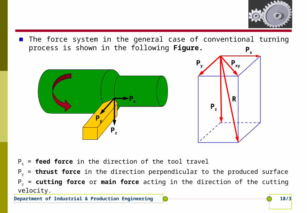
The force system in the general case of conventional turning process is shown in the following Figure.
Px
Py
Pz
Pz
Px
Py Pxy
R
Px = feed force in the direction of the tool travel
Py = thrust force in the direction perpendicular to the produced surface
Pz = cutting force or main force acting in the direction of the cutting velocity.

18/4Department of Industrial & Production Engineering
Pz
Px
PyPxy
X
Y
Πo
φ
PxyR
ZXY
R
.......[2]..........cosPP
]........[1..........sinPP
xyy
xyx
18/5Department of Industrial & Production Engineering
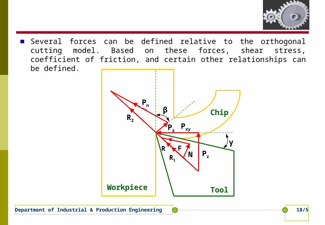
Several forces can be defined relative to the orthogonal cutting model. Based on these forces, shear stress, coefficient of friction, and certain other relationships can be defined.
R
Ps
R2
Workpiece Tool
Chip
γ
β
Pz
Pn
Pxy
NF
R1
18/6Department of Industrial & Production Engineering
Merchant Circle Diagram (MCD)
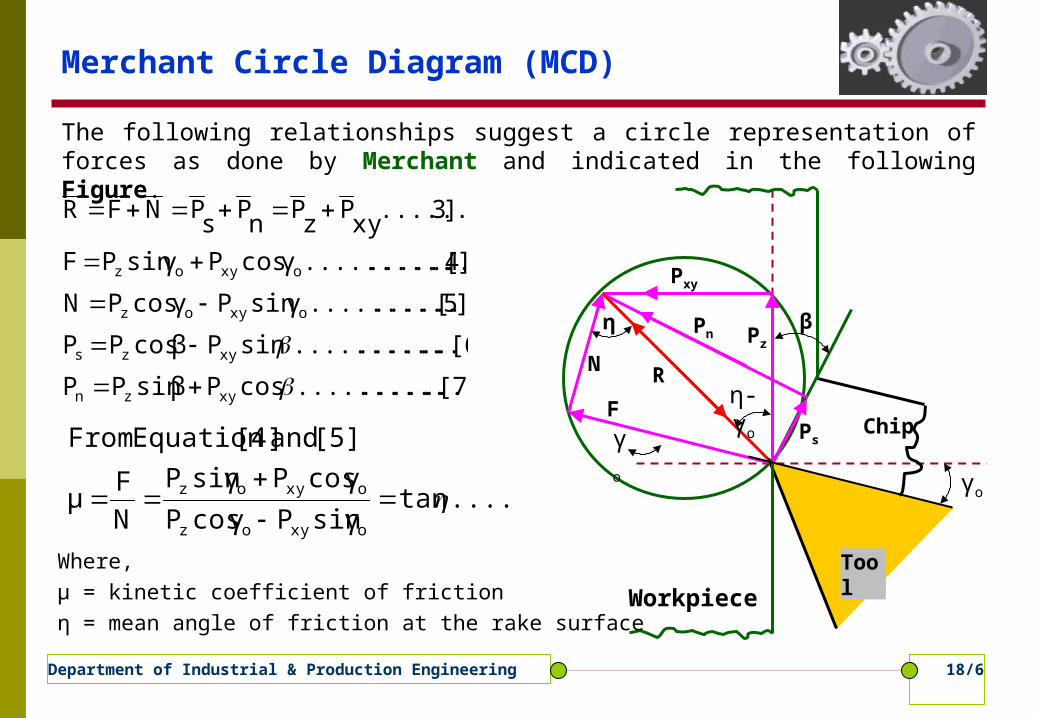
The following relationships suggest a circle representation of forces as done by Merchant and indicated in the following Figure.
Pxy
Workpiece
PzPn
PsF
N R
γo
γo
η β
η-γo
Tool
Chip
.[7].................... cosPβsin PP
..[6]....................sin Pβ cosPP
]5[....................sin γP γcosPN
]4.[.................... γcosPsin γPF
]3.......[xy
Pz
Pn
Ps
PNFR
xyzn
xyzs
oxyoz
oxyoz
.....[8]tansinγPcosγP
cosγPsinγP
N
Fμ
[5] and [4]Equation From
oxyoz
oxyoz
Where, μ = kinetic coefficient of friction η = mean angle of friction at the rake surface
18/7Department of Industrial & Production Engineering
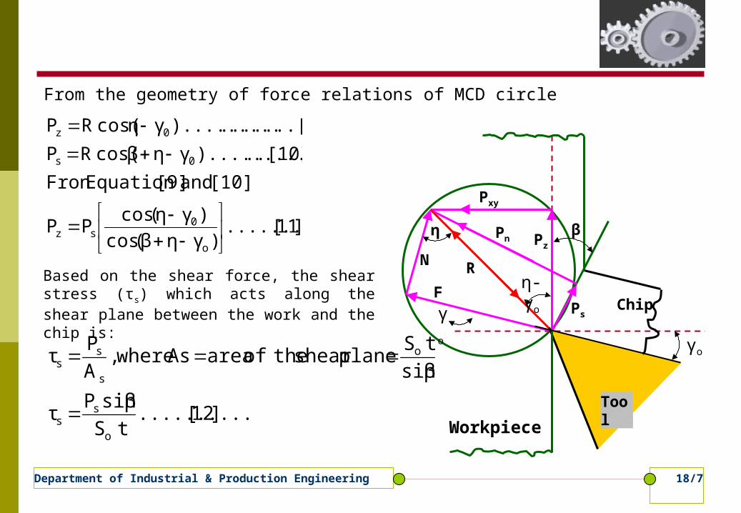
From the geometry of force relations of MCD circle
Pxy
Workpiece
PzPn
PsF
N R
γo
γo
η β
η-γo
Tool
Chip
]11[..........)γη(β cos
)γ(η cosPP
[10] and [9]Equation Fron
..[10]).........γηcos(βRP
.......[9]).........γcos(ηRP
o
0sz
0s
0z
Based on the shear force, the shear stress (τs) which acts along the shear plane between the work and the chip is:
]12[..........tS
sinβPτ
sinβ
tSplaneshear theof area As where,
A
Pτ
o
ss
o
s
ss

18/8Department of Industrial & Production Engineering
].......[14)γηcos(βsinβ
)γsin(ηtSτP
Similarly,
.[13]..........)γηcos(βsinβ
)γcos(ηtSτP
[12] [11]andEquation From
o
00sxy
o
00sz
Pxy
Workpiece
PzPn
PsF
N R
γo
γo
η β
η-γo
Tool
Chip
In metal cutting one of the main problem is to evaluate the cutting forces Pz and Pxy from the given cutting conditions and initial properties of work material and it is necessary to determine τs, β and η by suitable relationships.

18/9Department of Industrial & Production Engineering
Earnest-Merchant Theory
Ernst and Merchant extended their analysis and studied the relationship between the shear angle and the cutting conditions. They suggested that the shear angle always takes the value that reduces the total energy consumed in cutting to a minimum. Because the total work done in cutting is dependent upon and is a direct function of the component Pz of the cutting force, they developed an expression for Pz in terms of β and the constant properties of the workpiece material. Condition for maximum cutting force (Pz) from Equation [13]
...[16]..........cottSτ2P
[15] and [13]Equation Combining
]15........[..........
2
πcos0)γηβcos(βor 0,)γηsin(βsinβ)γηcos(βcosβ
0γηcos(βsinβ
)γηsin(βsinβ)γηcos(βcosβ)γcos(ηtSτ
0)γηcos(β
)γcos(η.
sinβ
tSτ
dβ
d
dβ
dPor, 0,
dβ
dP
0sz
000
20
0000s
o
00szz
20γ
2η
4π
β

18/10Department of Industrial & Production Engineering
Merchant Theory
Merchant modified the relationship derived by Earnest-Merchant, by assuming that the shear stress along the shear plane varies linearly with normal stress (σn). It is given as (from the following Figure).
σn
τs
τ0
k
]20...[.................... )
0γηtan(βk1
0τ
sτ
[19] and [17]Eqation From
[19].................... )0
γηtan(βs
τn
σ
)0
γηtan(βs
As
P
sA
nP
)0
γηtan(βs
Pn
P
......[18].......... )0
γηRsin(βn
P and )0
γηcos(βRs
P
MCD of relations force ofgeometry theFrom
]17......[..........n
σk0
τs
τ

18/11Department of Industrial & Production Engineering
Combining Equation [13] and [20]
]23[..........β)tan(ccotβt0
Ss
τz
P
[22] and [21]Equation From
]22.......[....................085to080c(k)1cot0
γη2β
k)0
γηcot(2β
0)0
γηsin(2βk)0
γηcos(2β
0)sin(sin)cos(sin
)cos(sin)sin(cos
)sin(sin)cos(cos)cos(
0)tan(1)cos(sin
)cos(or 0,
dβz
dP
[21]Equation from (Pz) force cutting maximumfor Condition
]21.....[..........)tan(1)cos(sin
)cos(
200
00
0000
00
00
00
00
k
kktS
or
k
tS
d
d
d
dP
k
tSP
s
oz
oz

18/12Department of Industrial & Production Engineering
Lee and Shaffer Theory
According to this theory the shear occurs on a single plane. So for a cutting process according to this theory, the following are supposed to hold good: The material ahead of the cutting tool behaved as ideal plastic material The chip does not get hardened The chip and parent work material are separated by a shear plane.
..[25]..........1tanγξtSτP
γtanξγcos
γsinξ
βtan
1βcot
Where,
....[25]..........1βcot tSτP
[24] and [13]Equation From
..[24]....................4
πγηβ
00sz
oo
o
0sz
0
Lee and Shaffer derived the following relationship as:
18/13Department of Industrial & Production Engineering
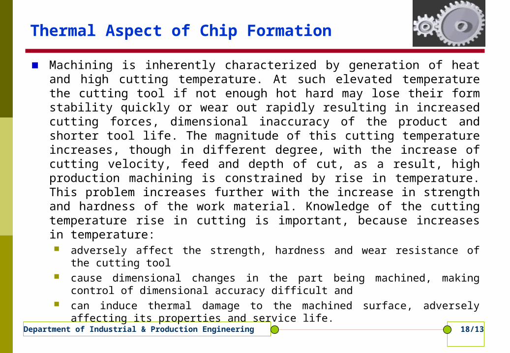
Thermal Aspect of Chip Formation
Machining is inherently characterized by generation of heat and high cutting temperature. At such elevated temperature the cutting tool if not enough hot hard may lose their form stability quickly or wear out rapidly resulting in increased cutting forces, dimensional inaccuracy of the product and shorter tool life. The magnitude of this cutting temperature increases, though in different degree, with the increase of cutting velocity, feed and depth of cut, as a result, high production machining is constrained by rise in temperature. This problem increases further with the increase in strength and hardness of the work material. Knowledge of the cutting temperature rise in cutting is important, because increases in temperature: adversely affect the strength, hardness and wear resistance of the cutting
tool cause dimensional changes in the part being machined, making control of
dimensional accuracy difficult and can induce thermal damage to the machined surface, adversely affecting its
properties and service life.

18/14Department of Industrial & Production Engineering
In addition, the machine tool itself may be subjected to temperature gradients, causing distortion of the machine. The main sources of heat in metal cutting are shown in the following Figure. These three distinct heat sources are: the shear zone (q1), where the main plastic
deformation takes place the chip-tool interface zone (q2), where secondary
plastic deformation due to friction between the heated chip and the tool takes place
the work tool interface (q3), at flanks where frictional rubbing occurs.
Workpiece Tool
Chipq1
q2q3
air gsurroundin theinto radiatedheat of
Amount workpiece theinto passingheat ofAmount toolcutting
in the remainingheat ofAmount chipsin away heat ofAmount
generatedheat of
amount Total
:as written becan formation chipin balanceheat The
18/15Department of Industrial & Production Engineering
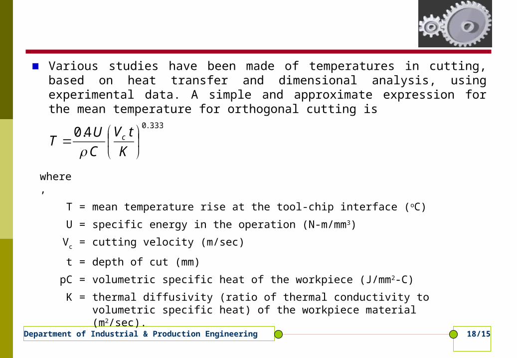
Various studies have been made of temperatures in cutting, based on heat transfer and dimensional analysis, using experimental data. A simple and approximate expression for the mean temperature for orthogonal cutting is
333..04.0
K
tV
C
UT c
where,
T = mean temperature rise at the tool-chip interface (oC)
U = specific energy in the operation (N-m/mm3)
Vc = cutting velocity (m/sec)
t = depth of cut (mm)
pC = volumetric specific heat of the workpiece (J/mm2-C)
K = thermal diffusivity (ratio of thermal conductivity to volumetric specific heat) of the workpiece material (m2/sec).

18/16Department of Industrial & Production Engineering
Exercise
The dynamometer recorded the following, feed force 200 kg, cutting force 300 kg. The rake angle of the tool used was 10o. The chip thickness ratio 0.35. Find
Shear angle (β) Shear force (Ps) Co-efficient of friction at the chip-tool interface (μ) and the friction angle (η) Compressive force at the shear plane (Pn).
A seamless tube 3cm outside diameter is reduced in length on a lathe with the help of a single point cutting tool. The cutting speed is 40 m/min, the depth of cut is 0.125mm. The length of continuous chips, for one revolution of the tube, on measurement comes to be 17.77cm. The cutting force is 200 kg and the feed force is 75 kg. the rake angle of the tool is 35o.Calculate,
Co-efficient of friction Chip thickness ratio Shear plane angle Velocity of the chip along the tool face Velocity of shear along the shear plane
18/17Department of Industrial & Production Engineering
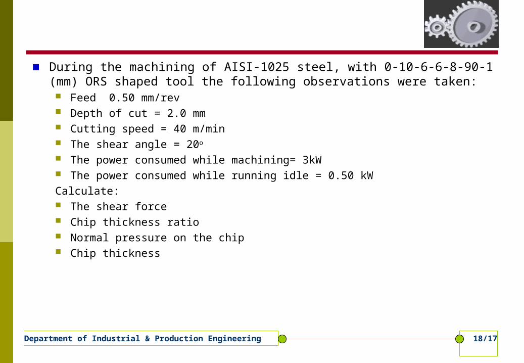
During the machining of AISI-1025 steel, with 0-10-6-6-8-90-1 (mm) ORS shaped tool the following observations were taken:
Feed 0.50 mm/rev Depth of cut = 2.0 mm Cutting speed = 40 m/min The shear angle = 20o
The power consumed while machining= 3kW The power consumed while running idle = 0.50 kWCalculate: The shear force Chip thickness ratio Normal pressure on the chip Chip thickness

18/18Department of Industrial & Production Engineering
Any questions or comments?