
Theory of Arched Structures - Springer978-1-4614-0469-9/1.pdfTheory of Arched Structures Strength,...
27
Theory of Arched Structures
Transcript of Theory of Arched Structures - Springer978-1-4614-0469-9/1.pdfTheory of Arched Structures Strength,...
Theory of Arched Structures


Igor A. Karnovsky
Theory of Arched Structures
Strength, Stability, Vibration
Igor A. KarnovskyNorthview Pl 811V3J 3R4 [email protected]
ISBN 978-1-4614-0468-2 e-ISBN 978-1-4614-0469-9DOI 10.1007/978-1-4614-0469-9Springer New York Dordrecht Heidelberg London
Library of Congress Control Number: 2011937582
# Springer Science+Business Media, LLC 2012All rights reserved. This work may not be translated or copied in whole or in part without the writtenpermission of the publisher (Springer Science+Business Media, LLC, 233 Spring Street, New York,NY 10013, USA), except for brief excerpts in connection with reviews or scholarly analysis. Use inconnection with any form of information storage and retrieval, electronic adaptation, computer software,or by similar or dissimilar methodology now known or hereafter developed is forbidden.The use in this publication of trade names, trademarks, service marks, and similar terms, even if theyare not identified as such, is not to be taken as an expression of opinion as to whether or not they aresubject to proprietary rights.
Printed on acid-free paper
Springer is part of Springer Science+Business Media (www.springer.com)

In memory of Prof. Anatoly B. Morgaevsky


Preface
In modern engineering, as a basis of construction, arches have a diverse range of
applications. Today the theory of arches has reached a level that is suitable for most
engineering applications. Many methods pertaining to arch analysis can be found in
scientific literature. However, most of this material is published in highly
specialized journals, obscure manuals, and inaccessible books. This is not
surprising, as the intensive development of arch theory, particularly stability and
vibration have mostly occurred in the 1940s to the 1960s. Therefore, most engineers
lack the opportunity to utilize these developments in their practice.
The author has committed to the goal of presenting a book which encompasses
essential and tested methods on fundamental methods of arch analysis and equally
important problems.
The objective of the Book is to provide to readers with detailed procedures for analysis ofthe strength, stability, and vibration of various types of arched structures, using exactanalytical methods of classical Structural Analysis.
In 2004, professor L.A. Godoy published the article “Arches: A Neglected Topicin Structural Analysis Courses.” This in-depth investigation highlights a deep rift
between the modern level of development of arch theory and the level of presenta-
tion of this theory in existing material on structural analysis.
In 2009, the author of this book, with co-author O. Lebed published the textbook
“Advanced Methods of Structural Analysis” (Springer), in which arch theory is
presented in a much greater depth and volume than in existing textbooks. However,
the issue of producing a single book which covers both general and specialized
problems of arches remained unsolved. The book presented here sheds light on
issues of strength, stability, and vibrations, as well as special problems of arches
and arched structures.
In this book special attention is directed toward the discussion of fundamental
properties of structures. An engineer who is armed with fundamental knowledge
and means of computation is essentially set to succeed in modern day engineering.
Solutions of problems of strength, stability, and vibrations of arches in most cases
vii

are broken down to basic formulas which can be easily applied to engineering
practice.
This book is based on the author’s experience as a teacher and consultant in
structural mechanics. It is intended for senior undergraduate students in structural
engineering and for postgraduate students who are concerned with different pro-
blems of arches structures. The book will be a useful reference for engineers in the
structural industry.
Vancouver, Canada Igor A. Karnovsky
viii Preface

Distribution of Material in the Book
This book contains an introduction, four parts (nine chapters), and an appendix.
The first part “Strength” contains three chapters. Chapter 1 is devoted to
fundamental methods of determining displacement of elastic structures in general
accompanied by examples specifically for arches.
Chapter 2 covers the analysis of three-hinged arches, while analysis of redundant
arches is considered in Chap. 3; in these chapters a special attention is dedicated to
the analysis of arched structures using influence lines.
Second part “Stability” contains two chapters. Chapter 4 provides analytical
methods of the stability of arches. These methods are based on the integration of
differential equations.
Chapter 5 presents Smirnov’s matrix method and approximate method. Approx-
imate method is based on the approximation of the arch by straight members with
subsequent application of the precise displacement method in canonical form.
The third part, “Vibration” contains two chapters. Chapter 6 deals with compu-
tation of eigenvalues and eigenfunctions for arches. For analysis of the circular
uniform arch, Lamb’s differential equation is used; for analysis of parabolic
uniform arch the Rabinovich’s model is applied. The frequency of vibration for
arches with different ratio “rise/span” of an arch are presented on the basis of this
model.
Chapter 7 presents forced vibrations of arches.
The fourth part of the book, “Special Topics” holds the goal of presenting
introductory information regarding problems which until now have only been
discussed in specialized literature. Chapter 8 contains the static nonlinear problems.
They are plastic analysis of the arches and arched structures with one-sided con-
straints. Chapter 9 is devoted to dynamical stability of arches, and dynamics of
arched structures subjected to moving inertial load.
Finally, the appendix contains the fundamental tabulated data essential for
engineering practice involving arches.
Sections 2.1, 2.2, 2.4, and 2.6 were written by Olga Lebed.
ix


Acknowledgments
First of all I must thank professor L.A. Godoy (University of Puerto Rico at
Mayaguez) and Steven Elliot (Senior Editor, Springer) who stimulated the creation
of this book.
I wish to express deep gratitude to Olga Lebed (Condor Rebar Consultants,
Vancouver, Canada) for the very constructive discussions of the book, organiza-
tional assistance, and writing four sections of the book.
A number of friends and colleagues have helped me directly or indirectly;
my sincere gratitude to professors Valeriy A. Baranenko (Chemical Technology
University, Ukraine), Jurij G. Kreimer (Civil Engineering University, Ukraine),
Vladimir M. Ovsjanko (Polytechnical University, Belorussia), P. Eng Tat’jana
Volina (Ukraine), as well as to members of the Russian National Library (Moscow)
for helping with the pursuit of difficult-to-access literature and documents.
I wish to express deep gratitude to Evgeniy Lebed (University of British
Columbia, Canada) for productive discussions and helpful criticism as well as
assisting with many numerical calculations and validation of results.
Many thanks to Tamara Moldon (Vancouver, Canada) for editing assistance.
I would like to thank all the staff of Springer who contributed to this project.
Finally, I would like to thank my relatives, many friends, and colleagues, who
have supported me through all stages of research and development of this book.
The author appreciates comments and suggestions to improve the current edi-
tion. All constructive criticism will be accepted with gratitude.
xi


Contents
Preface . . . . . . . . . . . . . . . . . . . . . . . . . . . . . . . . . . . . . . . . . . . . . . . . . . . . . . . . . . . . . . . . . . . . . . . . . vii
Introduction . . . . . . . . . . . . . . . . . . . . . . . . . . . . . . . . . . . . . . . . . . . . . . . . . . . . . . . . . . . . . . . . . . . xix
Part I Strength Analysis
1 Deflections of Elastic Structures. . . . . . . . . . . . . . . . . . . . . . . . . . . . . . . . . . . . . . . . 3
1.1 General . . . . . . . . . . . . . . . . . . . . . . . . . . . . . . . . . . . . . . . . . . . . . . . . . . . . . . . . . . . . . . 3
1.2 Initial Parameters Method . . . . . . . . . . . . . . . . . . . . . . . . . . . . . . . . . . . . . . . . . . 5
1.3 Maxwell–Mohr Integral. . . . . . . . . . . . . . . . . . . . . . . . . . . . . . . . . . . . . . . . . . . . . 10
1.3.1 Deflection Due to External Loads . . . . . . . . . . . . . . . . . . . . . . . . . . 10
1.3.2 Deflections Due to Change of Temperature . . . . . . . . . . . . . . . . 15
1.4 Graph Multiplication Method. . . . . . . . . . . . . . . . . . . . . . . . . . . . . . . . . . . . . . . 18
1.4.1 Vereshchagin Rule . . . . . . . . . . . . . . . . . . . . . . . . . . . . . . . . . . . . . . . . . . 19
1.4.2 Trapezoid and Simpson Rules . . . . . . . . . . . . . . . . . . . . . . . . . . . . . . 20
1.4.3 Signs Rule . . . . . . . . . . . . . . . . . . . . . . . . . . . . . . . . . . . . . . . . . . . . . . . . . . . 21
1.5 Maxwell–Mohr Formula for Curvilinear Rods . . . . . . . . . . . . . . . . . . . . . 24
1.6 Elastic Loads Method . . . . . . . . . . . . . . . . . . . . . . . . . . . . . . . . . . . . . . . . . . . . . . . 26
1.6.1 Computation of Elastic Load . . . . . . . . . . . . . . . . . . . . . . . . . . . . . . . 26
1.6.2 Expanded Form for Elastic Loads . . . . . . . . . . . . . . . . . . . . . . . . . . 30
1.7 Differential Relationships for Curvilinear Rods. . . . . . . . . . . . . . . . . . . . 36
1.7.1 Relationships Between Internal Forces . . . . . . . . . . . . . . . . . . . . . 36
1.7.2 Relationships Between Displacements and Strains. . . . . . . . . 39
1.7.3 Lamb’s Equation . . . . . . . . . . . . . . . . . . . . . . . . . . . . . . . . . . . . . . . . . . . . 41
1.8 Reciprocal Theorems . . . . . . . . . . . . . . . . . . . . . . . . . . . . . . . . . . . . . . . . . . . . . . . 42
1.8.1 Theorem of Reciprocal Works (Betti Theorem) . . . . . . . . . . . 42
1.8.2 Theorem of Reciprocal Displacements
(Maxwell Theorem) . . . . . . . . . . . . . . . . . . . . . . . . . . . . . . . . . . . . . . . . . 43
1.8.3 Theorem of Reciprocal Reactions
(Rayleigh First Theorem) . . . . . . . . . . . . . . . . . . . . . . . . . . . . . . . . . . . 44
xiii
1.8.4 Theorem of Reciprocal Displacements
and Reactions (Rayleigh Second Theorem) . . . . . . . . . . . . . . 45
1.8.5 Transfer Matrix . . . . . . . . . . . . . . . . . . . . . . . . . . . . . . . . . . . . . . . . . . . 46
1.9 Boussinesq’s Equation. . . . . . . . . . . . . . . . . . . . . . . . . . . . . . . . . . . . . . . . . . . . . 46
1.9.1 Two Forms of Boussinesq’s Equation. . . . . . . . . . . . . . . . . . . . 46
1.9.2 Displacements of a Circular Rod . . . . . . . . . . . . . . . . . . . . . . . . . 48
2 Three-Hinged Arches . . . . . . . . . . . . . . . . . . . . . . . . . . . . . . . . . . . . . . . . . . . . . . . . . . . . 55
2.1 General. . . . . . . . . . . . . . . . . . . . . . . . . . . . . . . . . . . . . . . . . . . . . . . . . . . . . . . . . . . . . 55
2.2 Reactions of Supports and Internal Forces . . . . . . . . . . . . . . . . . . . . . . . . 57
2.3 Rational Shape of the Arch. . . . . . . . . . . . . . . . . . . . . . . . . . . . . . . . . . . . . . . . 63
2.3.1 Vertical Load Does Not Depend on the Shape
of the Arch . . . . . . . . . . . . . . . . . . . . . . . . . . . . . . . . . . . . . . . . . . . . . . . . 63
2.3.2 Vertical Load Depends on Arch Shape . . . . . . . . . . . . . . . . . . 65
2.3.3 Radial Load . . . . . . . . . . . . . . . . . . . . . . . . . . . . . . . . . . . . . . . . . . . . . . . 68
2.4 Influence Lines for Reactions and Internal Forces . . . . . . . . . . . . . . . . 68
2.4.1 Analytical Approach. . . . . . . . . . . . . . . . . . . . . . . . . . . . . . . . . . . . . . 69
2.4.2 Nil Points Method . . . . . . . . . . . . . . . . . . . . . . . . . . . . . . . . . . . . . . . . 75
2.4.3 Fictitious Beam Method . . . . . . . . . . . . . . . . . . . . . . . . . . . . . . . . . . 78
2.4.4 Application of Influence Lines . . . . . . . . . . . . . . . . . . . . . . . . . . . 81
2.5 Core Moments and Normal Stresses . . . . . . . . . . . . . . . . . . . . . . . . . . . . . . 86
2.5.1 Normal Stresses. . . . . . . . . . . . . . . . . . . . . . . . . . . . . . . . . . . . . . . . . . . 86
2.5.2 Influence Lines for Core Moments . . . . . . . . . . . . . . . . . . . . . . . 87
2.6 Special Types of Three-Hinged Arches . . . . . . . . . . . . . . . . . . . . . . . . . . . 89
2.6.1 Arch with Elevated Simple Tie. . . . . . . . . . . . . . . . . . . . . . . . . . . 89
2.6.2 Arch with Complex Tie . . . . . . . . . . . . . . . . . . . . . . . . . . . . . . . . . . 94
2.6.3 Askew Arch. . . . . . . . . . . . . . . . . . . . . . . . . . . . . . . . . . . . . . . . . . . . . . . 98
2.6.4 Latticed Askew Arch . . . . . . . . . . . . . . . . . . . . . . . . . . . . . . . . . . . . 101
2.7 Complex Arched Structures . . . . . . . . . . . . . . . . . . . . . . . . . . . . . . . . . . . . . . 103
2.7.1 Multispan Three-Hinged Arched Structure . . . . . . . . . . . . . 103
2.7.2 Arched Combined Structures . . . . . . . . . . . . . . . . . . . . . . . . . . . . 105
2.8 Deflection of Three-Hinged Arches Due to External Loads . . . . . 112
2.8.1 Uniform Circular Arch: Exact Solution . . . . . . . . . . . . . . . . . 113
2.8.2 Nonuniform Arch of Arbitrary Shape:
Approximate Solution . . . . . . . . . . . . . . . . . . . . . . . . . . . . . . . . . . . 114
2.9 Displacement Due to Settlement of Supports
and Errors of Fabrication . . . . . . . . . . . . . . . . . . . . . . . . . . . . . . . . . . . . . . . . . 117
2.9.1 Settlements of Supports . . . . . . . . . . . . . . . . . . . . . . . . . . . . . . . . . 118
2.9.2 Errors of Fabrication. . . . . . . . . . . . . . . . . . . . . . . . . . . . . . . . . . . . . 120
2.10 Matrix Form Analysis of Arches Subjected to Fixed
and Moving Load . . . . . . . . . . . . . . . . . . . . . . . . . . . . . . . . . . . . . . . . . . . . . . . . . 121
3 Redundant Arches . . . . . . . . . . . . . . . . . . . . . . . . . . . . . . . . . . . . . . . . . . . . . . . . . . . . . . 125
3.1 Types, Forms, and Peculiarities of Redundant Arches. . . . . . . . . . . 125
3.1.1 Two-Hinged Arch . . . . . . . . . . . . . . . . . . . . . . . . . . . . . . . . . . . . . . . 126
3.1.2 Hingeless Arch. . . . . . . . . . . . . . . . . . . . . . . . . . . . . . . . . . . . . . . . . . . 127
xiv Contents
3.2 Force Method . . . . . . . . . . . . . . . . . . . . . . . . . . . . . . . . . . . . . . . . . . . . . . . . . . . . . 128
3.2.1 Primary System and Primary Unknowns. . . . . . . . . . . . . . . . 128
3.2.2 Canonical Equations of the Force Method . . . . . . . . . . . . . . 128
3.2.3 Unit and Loading Displacements. . . . . . . . . . . . . . . . . . . . . . . . 131
3.2.4 Procedure for Analysis . . . . . . . . . . . . . . . . . . . . . . . . . . . . . . . . . . 132
3.3 Arches Subjected to Fixed Loads . . . . . . . . . . . . . . . . . . . . . . . . . . . . . . . . 133
3.3.1 Parabolic Two-Hinged Uniform Arch. . . . . . . . . . . . . . . . . . . 133
3.3.2 Some Comments About Rational Axis . . . . . . . . . . . . . . . . . . 139
3.4 Symmetrical Arches . . . . . . . . . . . . . . . . . . . . . . . . . . . . . . . . . . . . . . . . . . . . . . 140
3.4.1 Properties of Symmetrical Structures . . . . . . . . . . . . . . . . . . . 140
3.4.2 Elastic Center . . . . . . . . . . . . . . . . . . . . . . . . . . . . . . . . . . . . . . . . . . . . 141
3.4.3 Parabolic Hingeless Nonuniform Arch. . . . . . . . . . . . . . . . . . 145
3.4.4 Circular Hingeless Uniform Arch . . . . . . . . . . . . . . . . . . . . . . . 148
3.5 Settlements of Supports . . . . . . . . . . . . . . . . . . . . . . . . . . . . . . . . . . . . . . . . . . 150
3.5.1 Two-Hinged Arch . . . . . . . . . . . . . . . . . . . . . . . . . . . . . . . . . . . . . . . 150
3.5.2 Hingeless Arch. . . . . . . . . . . . . . . . . . . . . . . . . . . . . . . . . . . . . . . . . . . 151
3.6 Arches with Elastic Supports . . . . . . . . . . . . . . . . . . . . . . . . . . . . . . . . . . . . . 153
3.7 Arches with Elastic Tie. . . . . . . . . . . . . . . . . . . . . . . . . . . . . . . . . . . . . . . . . . . 156
3.7.1 Semicircular Uniform Arch . . . . . . . . . . . . . . . . . . . . . . . . . . . . . 157
3.7.2 Nonuniform Arch of Arbitrary Shape . . . . . . . . . . . . . . . . . . . 159
3.8 Special Effects . . . . . . . . . . . . . . . . . . . . . . . . . . . . . . . . . . . . . . . . . . . . . . . . . . . . 162
3.8.1 Change of Temperature. . . . . . . . . . . . . . . . . . . . . . . . . . . . . . . . . . 162
3.8.2 Shrinkage of Concrete . . . . . . . . . . . . . . . . . . . . . . . . . . . . . . . . . . . 166
3.9 Influence Lines. . . . . . . . . . . . . . . . . . . . . . . . . . . . . . . . . . . . . . . . . . . . . . . . . . . . 166
3.9.1 Two-Hinged Parabolic Nonuniform Arch. . . . . . . . . . . . . . . 167
3.9.2 Two-Hinged Circular Uniform
Arch with Elastic Tie . . . . . . . . . . . . . . . . . . . . . . . . . . . . . . . . . . . . 170
3.9.3 Hingeless Nonuniform Parabolic Arch. . . . . . . . . . . . . . . . . . 172
3.9.4 Application of Influence Lines . . . . . . . . . . . . . . . . . . . . . . . . . . 179
3.10 Arch Subjected to Radial Pressure . . . . . . . . . . . . . . . . . . . . . . . . . . . . . . . 181
3.10.1 Internal Forces Taking into Account
and Neglecting Shrinkage . . . . . . . . . . . . . . . . . . . . . . . . . . . . . . . 182
3.10.2 Complex Loading of Circular Arch . . . . . . . . . . . . . . . . . . . . . 184
3.11 Deflections of the Arches. . . . . . . . . . . . . . . . . . . . . . . . . . . . . . . . . . . . . . . . . 187
3.11.1 Deflections at the Discrete Points
of Redundant Arches . . . . . . . . . . . . . . . . . . . . . . . . . . . . . . . . . . . . 188
3.11.2 Effect of Axial Forces . . . . . . . . . . . . . . . . . . . . . . . . . . . . . . . . . . . 189
3.12 Arch Loaded Orthogonally to the Plane of Curvature . . . . . . . . . . . 192
Part II Stability Analysis
4 Elastic Stability of Arches . . . . . . . . . . . . . . . . . . . . . . . . . . . . . . . . . . . . . . . . . . . . . 197
4.1 General. . . . . . . . . . . . . . . . . . . . . . . . . . . . . . . . . . . . . . . . . . . . . . . . . . . . . . . . . . . . 197
4.1.1 Fundamental Concepts. . . . . . . . . . . . . . . . . . . . . . . . . . . . . . . . . . . 198
4.1.2 Forms of the Loss of Stability of the Arches. . . . . . . . . . . . 198
Contents xv

4.1.3 Differential Equations of Stability
of Curvilinear Rod . . . . . . . . . . . . . . . . . . . . . . . . . . . . . . . . . . . . . . . . . 200
4.1.4 Methods of Analysis . . . . . . . . . . . . . . . . . . . . . . . . . . . . . . . . . . . . . . . 201
4.2 Circular Arches Subjected to Radial Load . . . . . . . . . . . . . . . . . . . . . . . . 201
4.2.1 Solution Based on the Boussinesq’s Equation. . . . . . . . . . . . . 202
4.2.2 Solution Based on the Lamb’s Equation . . . . . . . . . . . . . . . . . . 207
4.2.3 Arch with Specific Boundary Conditions. . . . . . . . . . . . . . . . . . 211
4.3 Circular Arches with Elastic Supports. . . . . . . . . . . . . . . . . . . . . . . . . . . . . 212
4.3.1 General Solution and Special Cases . . . . . . . . . . . . . . . . . . . . . . . 212
4.3.2 Complex Arched Structure. . . . . . . . . . . . . . . . . . . . . . . . . . . . . . . . . 217
4.4 Gentle Circular Arch Subjected to Radial Load. . . . . . . . . . . . . . . . . . . 218
4.4.1 Mathematical Model and Bubnov–Galerkin
Procedure. . . . . . . . . . . . . . . . . . . . . . . . . . . . . . . . . . . . . . . . . . . . . . . . . . . 219
4.4.2 Two-Hinged Arch . . . . . . . . . . . . . . . . . . . . . . . . . . . . . . . . . . . . . . . . . . 220
4.4.3 Graphical Interpretation of Results . . . . . . . . . . . . . . . . . . . . . . . . 221
4.4.4 Hingeless Arch . . . . . . . . . . . . . . . . . . . . . . . . . . . . . . . . . . . . . . . . . . . . . 223
4.5 Parabolic Arch . . . . . . . . . . . . . . . . . . . . . . . . . . . . . . . . . . . . . . . . . . . . . . . . . . . . . 223
4.5.1 Dinnik’s Equation. . . . . . . . . . . . . . . . . . . . . . . . . . . . . . . . . . . . . . . . . . 223
4.5.2 Nonuniform Arches . . . . . . . . . . . . . . . . . . . . . . . . . . . . . . . . . . . . . . . . 225
4.5.3 Partial Loading . . . . . . . . . . . . . . . . . . . . . . . . . . . . . . . . . . . . . . . . . . . . . 226
4.6 Parabolic Arch with Tie . . . . . . . . . . . . . . . . . . . . . . . . . . . . . . . . . . . . . . . . . . . 227
4.7 Out-of-Plane Loss of Stability of a Single Arch . . . . . . . . . . . . . . . . . . 229
4.7.1 Circular Arch Subjected to Couples
on the Ends. . . . . . . . . . . . . . . . . . . . . . . . . . . . . . . . . . . . . . . . . . . . . . . . . 229
4.7.2 Circular Arch Subjected to Uniform Radial Load. . . . . . . . . 230
4.7.3 Parabolic Arch Subjected to Uniform Vertical Load. . . . . . 231
5 Matrix and Displacement Methods . . . . . . . . . . . . . . . . . . . . . . . . . . . . . . . . . . . 233
5.1 General . . . . . . . . . . . . . . . . . . . . . . . . . . . . . . . . . . . . . . . . . . . . . . . . . . . . . . . . . . . . . 233
5.2 Smirnov Matrix Method . . . . . . . . . . . . . . . . . . . . . . . . . . . . . . . . . . . . . . . . . . . 234
5.2.1 Matrix Form for Elastic Loads. . . . . . . . . . . . . . . . . . . . . . . . . . . . . 234
5.2.2 Moment Influence Matrix. . . . . . . . . . . . . . . . . . . . . . . . . . . . . . . . . . 237
5.2.3 Stability Equation in Matrix Form. . . . . . . . . . . . . . . . . . . . . . . . . 238
5.3 Two-Hinged Symmetrical Arches . . . . . . . . . . . . . . . . . . . . . . . . . . . . . . . . . 239
5.3.1 Circular Uniform Arch. . . . . . . . . . . . . . . . . . . . . . . . . . . . . . . . . . . . . 239
5.3.2 Circular Nonuniform Arch. . . . . . . . . . . . . . . . . . . . . . . . . . . . . . . . . 240
5.3.3 Parabolic Uniform Arch . . . . . . . . . . . . . . . . . . . . . . . . . . . . . . . . . . . 242
5.4 Hingeless Symmetrical Arches . . . . . . . . . . . . . . . . . . . . . . . . . . . . . . . . . . . . 246
5.4.1 Duality of Bending Moment Diagram
and Influence Line . . . . . . . . . . . . . . . . . . . . . . . . . . . . . . . . . . . . . . . . . 246
5.4.2 Parabolic Uniform Arch . . . . . . . . . . . . . . . . . . . . . . . . . . . . . . . . . . . 249
5.5 Arch with Complex Tie . . . . . . . . . . . . . . . . . . . . . . . . . . . . . . . . . . . . . . . . . . . . 251
5.6 Displacement Method. . . . . . . . . . . . . . . . . . . . . . . . . . . . . . . . . . . . . . . . . . . . . . 255
5.6.1 General . . . . . . . . . . . . . . . . . . . . . . . . . . . . . . . . . . . . . . . . . . . . . . . . . . . . . 255
5.6.2 Two-Hinged Arch . . . . . . . . . . . . . . . . . . . . . . . . . . . . . . . . . . . . . . . . . . 259
5.7 Comparison of the Smirnov’s and Displacement Methods . . . . . . . 265
xvi Contents

Part III Vibration Analysis
6 Free Vibration of Arches . . . . . . . . . . . . . . . . . . . . . . . . . . . . . . . . . . . . . . . . . . . . . . 269
6.1 Fundamental Concepts. . . . . . . . . . . . . . . . . . . . . . . . . . . . . . . . . . . . . . . . . . . . 269
6.1.1 General. . . . . . . . . . . . . . . . . . . . . . . . . . . . . . . . . . . . . . . . . . . . . . . . . . . 269
6.1.2 Discrete Models of the Arches . . . . . . . . . . . . . . . . . . . . . . . . . . 272
6.2 Eigenvalues and Eigenfunctions of Arches
with Finite Number Degrees of Freedom . . . . . . . . . . . . . . . . . . . . . . . . 275
6.2.1 Differential Equations of Vibration . . . . . . . . . . . . . . . . . . . . . 275
6.2.2 Frequency Equation . . . . . . . . . . . . . . . . . . . . . . . . . . . . . . . . . . . . . 276
6.2.3 Mode Shape of Vibration. . . . . . . . . . . . . . . . . . . . . . . . . . . . . . . . 277
6.3 Examples. . . . . . . . . . . . . . . . . . . . . . . . . . . . . . . . . . . . . . . . . . . . . . . . . . . . . . . . . . 278
6.4 Vibration of Circular Uniform Arches . . . . . . . . . . . . . . . . . . . . . . . . . . . 286
6.4.1 Lamb’s Differential Equation of In-Plane
Bending Vibration . . . . . . . . . . . . . . . . . . . . . . . . . . . . . . . . . . . . . . . 286
6.4.2 Frequency Equation of Bending Vibration.
Demidovich’s Solution . . . . . . . . . . . . . . . . . . . . . . . . . . . . . . . . . . 287
6.4.3 Variational Approach . . . . . . . . . . . . . . . . . . . . . . . . . . . . . . . . . . . . 290
6.4.4 Radial Vibration . . . . . . . . . . . . . . . . . . . . . . . . . . . . . . . . . . . . . . . . . 292
6.5 Rabinovich’s Method for Parabolic Arch . . . . . . . . . . . . . . . . . . . . . . . . 293
6.5.1 Geometry of Parabolic Polygon . . . . . . . . . . . . . . . . . . . . . . . . 294
6.5.2 Kinematics of Parabolic Polygon. . . . . . . . . . . . . . . . . . . . . . . 295
6.5.3 Inertial Forces. . . . . . . . . . . . . . . . . . . . . . . . . . . . . . . . . . . . . . . . . . . 299
6.6 Symmetrical Vibrations of Three-Hinged Parabolic Arch . . . . . . . 301
6.6.1 Equivalent Design Diagram. Displacements . . . . . . . . . . . . 302
6.6.2 Frequencies and Mode Shape of Vibrations . . . . . . . . . . . . 306
6.6.3 Internal Forces for First and Second
Modes of Vibration . . . . . . . . . . . . . . . . . . . . . . . . . . . . . . . . . . . . . . 310
6.7 Antisymmetrical Vibration of Three-Hinged
Parabolic Arch . . . . . . . . . . . . . . . . . . . . . . . . . . . . . . . . . . . . . . . . . . . . . . . . . . . . 312
6.7.1 Equivalent Design Diagram. Displacements . . . . . . . . . . . . 312
6.7.2 Frequencies and Mode Shape of Vibrations . . . . . . . . . . . . 316
6.8 Parabolic Two-Hinged Uniform Arch. . . . . . . . . . . . . . . . . . . . . . . . . . . . 318
6.8.1 Symmetrical Vibration . . . . . . . . . . . . . . . . . . . . . . . . . . . . . . . . . . 319
6.8.2 Advantages and Disadvantage
of the Rabinovich’ Method. . . . . . . . . . . . . . . . . . . . . . . . . . . . . . 322
6.9 Parabolic Nonuniform Hingeless Arch. . . . . . . . . . . . . . . . . . . . . . . . . . . 323
6.10 Rayleigh–Ritz Method. . . . . . . . . . . . . . . . . . . . . . . . . . . . . . . . . . . . . . . . . . . . 325
6.10.1 Circular Uniform Arch. . . . . . . . . . . . . . . . . . . . . . . . . . . . . . . . . . . 325
6.10.2 Circular Arch with Piecewise Constant Rigidity. . . . . . . . 326
6.11 Conclusion . . . . . . . . . . . . . . . . . . . . . . . . . . . . . . . . . . . . . . . . . . . . . . . . . . . . . . . . 329
Contents xvii
7 Forced Vibrations of Arches. . . . . . . . . . . . . . . . . . . . . . . . . . . . . . . . . . . . . . . . . . . 331
7.1 General . . . . . . . . . . . . . . . . . . . . . . . . . . . . . . . . . . . . . . . . . . . . . . . . . . . . . . . . . . . . . 331
7.1.1 Types of Disturbing Loads. . . . . . . . . . . . . . . . . . . . . . . . . . . . . . . . . 331
7.1.2 Classification of Forced Vibration . . . . . . . . . . . . . . . . . . . . . . . . . 332
7.2 Structures with One Degree of Freedom . . . . . . . . . . . . . . . . . . . . . . . . . . 332
7.2.1 Dugamel Integral. . . . . . . . . . . . . . . . . . . . . . . . . . . . . . . . . . . . . . . . . . . 333
7.2.2 Application of the Duhamel Integral
for a Bar Structure . . . . . . . . . . . . . . . . . . . . . . . . . . . . . . . . . . . . . . . . . 333
7.2.3 Special Types of Disturbance Forces . . . . . . . . . . . . . . . . . . . . . . 334
7.3 The Steady-State Vibrations of the Structure
with a Finite Number of Degrees of Freedom. . . . . . . . . . . . . . . . . . . . . 342
7.3.1 Application of the Force Method . . . . . . . . . . . . . . . . . . . . . . . . . . 343
7.3.2 The Steady-State Vibrations of the Arch . . . . . . . . . . . . . . . . . . 344
7.4 Transient Vibration of the Arch . . . . . . . . . . . . . . . . . . . . . . . . . . . . . . . . . . . 347
7.4.1 Procedure of Analysis. . . . . . . . . . . . . . . . . . . . . . . . . . . . . . . . . . . . . . 347
7.4.2 Impulsive Load. . . . . . . . . . . . . . . . . . . . . . . . . . . . . . . . . . . . . . . . . . . . . 348
Part IV Special Arch Problems
8 Special Statics Topics . . . . . . . . . . . . . . . . . . . . . . . . . . . . . . . . . . . . . . . . . . . . . . . . . . 353
8.1 Plastic Analysis of the Arches . . . . . . . . . . . . . . . . . . . . . . . . . . . . . . . . . . . . . 353
8.1.1 Idealized Stress–Strain Diagrams. . . . . . . . . . . . . . . . . . . . . . . . . . 354
8.1.2 Direct Method of Plastic Analysis . . . . . . . . . . . . . . . . . . . . . . . . . 357
8.1.3 Mechanisms of Failure in Arches. . . . . . . . . . . . . . . . . . . . . . . . . . 361
8.1.4 Limiting Plastic Analysis of Parabolic Arches . . . . . . . . . . . . 361
8.2 Arched Structures with One-Sided Constraints . . . . . . . . . . . . . . . . . . . 365
8.2.1 General Properties of Structures
with One-Sided Constraints. . . . . . . . . . . . . . . . . . . . . . . . . . . . . . . . 365
8.2.2 Criteria of the Working System . . . . . . . . . . . . . . . . . . . . . . . . . . . 366
8.2.3 Analysis of Structures with One-Sided Constraints . . . . . . . 366
9 Special Stability and Dynamic Topics . . . . . . . . . . . . . . . . . . . . . . . . . . . . . . . . 371
9.1 Dynamical Stability of Arches. . . . . . . . . . . . . . . . . . . . . . . . . . . . . . . . . . . . . 371
9.1.1 Dynamical Stability of a Simply Supported Column . . . . . 372
9.1.2 Ince–Strutt Diagram. . . . . . . . . . . . . . . . . . . . . . . . . . . . . . . . . . . . . . . . 373
9.1.3 Dynamical Stability of Circular Arch . . . . . . . . . . . . . . . . . . . . . 374
9.2 Arched Structure Subjected to Moving Loads . . . . . . . . . . . . . . . . . . . . 377
9.2.1 Beam with a Traveling Load . . . . . . . . . . . . . . . . . . . . . . . . . . . . . . 377
9.2.2 Arch Subjected to Inertial Traveling Load:
Morgaevsky Solution . . . . . . . . . . . . . . . . . . . . . . . . . . . . . . . . . . . . . . 380
10 Conclusion . . . . . . . . . . . . . . . . . . . . . . . . . . . . . . . . . . . . . . . . . . . . . . . . . . . . . . . . . . . . . . 385
Appendix . . . . . . . . . . . . . . . . . . . . . . . . . . . . . . . . . . . . . . . . . . . . . . . . . . . . . . . . . . . . . . . . . . . . . 387
Bibliography . . . . . . . . . . . . . . . . . . . . . . . . . . . . . . . . . . . . . . . . . . . . . . . . . . . . . . . . . . . . . . . . . 417
Index . . . . . . . . . . . . . . . . . . . . . . . . . . . . . . . . . . . . . . . . . . . . . . . . . . . . . . . . . . . . . . . . . . . . . . . . . . 425
xviii Contents
Introduction
Arches and arched structures have a wide range of uses in bridges, arched dams and
in industrial, commercial, and recreational buildings. They represent the primary
structural components of important and expensive structures, many of which are
unique. Current trends in architecture heavily rely on arched building components
due to their strengths and architectural appeal.
Complex structural analysis of arches is related to the analysis of the arches
strength, stability, and vibration. This type of multidimensional analysis aims at
ensuring the proper functionality of an arch as one of the fundamental structural
elements.
Terminology
We start our consideration from terminology for a bridge arch (Fig. 1a). The arch
is supported by abutments. The heels and crown are the lowest and highest points
of the arch, respectively; supports may be rolled, pinned, or fixed. Horizontal
distance between two heels is span l, a vertical distance between heels line and
crown is rise f. Extrados is the top outer surface of the arch. Intrados is the lower
inner surface of the arch. A body of the arch itself may be solid or with webbed
members.
As a bridge trusses, the bridge arches are connected using arch bracing.
All structural members over the arch are called overarched construction. Deck
and arch are connected by vertical members called posts. If the roadway is located
below an arch, then vertical members are called hangers. If movement of vehicles is
at the intermediate level, then a loaded deck is partially connected with arch by
poles and partially by hangers. The posts are compressed, while the hangers are
extended.
For structural analysis, a real structure has to be presented in the idealized and
simplified form using the axial line of the structural components. For this, a so-
xix
called design diagram of the real structure is used. Design diagram is a critically
important concept of structural analysis. Design diagram of a real structure reflects
the most important and primary features of the structure such as types of members,
types of supports, types of joints, while some features of secondary importance
(shapes of cross-sections of members, existence of local reinforcements or holes,
size of supports and joints, etc.) are ignored.
Few general rules of representing a real structure by its design diagram are:
l A structure is presented as a set of simple structural membersl Real supports are replaced by their idealized supportsl Any connection between members of a structure are replaced by idealized jointsl Cross-section of any member is characterized by its area or/and moment of
inertia
It is obvious that a real structure may be represented using different design
diagrams.
An arch with overarched members and its design diagram is shown in Fig. 1b.
Design diagram also contains information about the shape of the neutral line of the
arch. Usually this shape is given by the expression y ¼ f ðxÞ.Note that posts or hangers are connected to the arch itself by means of hinges.
In bridge construction the arches are subdivided into deck-bridge arch (Fig. 1),
through-bridge arch, and arch with deck at some intermediate level (Fig. 2).
Also, double-deck bridges exist with the lower deck designed for a railway, and
the upper deck is utilized for a roadway.
x
y
y=f(x)
l
f
A B
C
b
Arch bracing Arch
Span
Deck loads Arch post
Abutment
Roadway
Crown
Rise Extrados
Intrados
HeelCrown depth
a
Plan
Fig. 1 (a, b) Components of an arch bridge and design diagrams for a deck-arch bridge
xx Introduction
Based on their design, arches are divided into hingeless (arch with fixed
ends), one-hinged, two-hinged, and three-hinged ones (Fig. 3a–d). All arches
presented in Fig. 3, except for the three-hinged arch (d), are statically indeterminate
(redundant) ones.
A tie is an additional member which allows us to reinforce an arch. A single tie
may be installed on the level of the supports (Fig. 4a), or elevated (b). The tie may
also be complex (c). Prestressed tie allows us to control the internal forces in the
arch itself.
The aches may be constructed with supports at different elevations. In this case
they are called askew arches.
Peculiarities of Arch Behavior
Since posts have hinges at the ends (Fig. 2), then only axial force arises in them.
If the posts with fixed ends are thin elements with small flexural stiffness, then they
cannot perceive and transmit the bending moments. In both cases, the loads from
deck are transferred through posts (hangers) on the arch as concentrated forces.
Fig. 2 Design diagrams of the through-bridge arch and arch with deck at intermediate level
b
c d
a
Fig. 3 Design diagrams of arches: (a) hingeless arch; (b) two-hinged arch; (c) one-hinged arch;
(d) three-hinged arch
tie
a b cElevated
tieComplex
tie
Fig. 4 Arches with tie
Introduction xxi
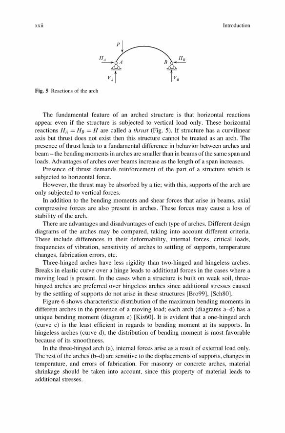
The fundamental feature of an arched structure is that horizontal reactions
appear even if the structure is subjected to vertical load only. These horizontal
reactions HA ¼ HB ¼ H are called a thrust (Fig. 5). If structure has a curvilinear
axis but thrust does not exist then this structure cannot be treated as an arch. The
presence of thrust leads to a fundamental difference in behavior between arches and
beam – the bendingmoments in arches are smaller than in beams of the same span and
loads. Advantages of arches over beams increase as the length of a span increases.
Presence of thrust demands reinforcement of the part of a structure which is
subjected to horizontal force.
However, the thrust may be absorbed by a tie; with this, supports of the arch are
only subjected to vertical forces.
In addition to the bending moments and shear forces that arise in beams, axial
compressive forces are also present in arches. These forces may cause a loss of
stability of the arch.
There are advantages and disadvantages of each type of arches. Different design
diagrams of the arches may be compared, taking into account different criteria.
These include differences in their deformability, internal forces, critical loads,
frequencies of vibration, sensitivity of arches to settling of supports, temperature
changes, fabrication errors, etc.
Three-hinged arches have less rigidity than two-hinged and hingeless arches.
Breaks in elastic curve over a hinge leads to additional forces in the cases where a
moving load is present. In the cases when a structure is built on weak soil, three-
hinged arches are preferred over hingeless arches since additional stresses caused
by the settling of supports do not arise in these structures [Bro99], [Sch80].
Figure 6 shows characteristic distribution of the maximum bending moments in
different arches in the presence of a moving load; each arch (diagrams a–d) has a
unique bending moment (diagram e) [Kis60]. It is evident that a one-hinged arch
(curve c) is the least efficient in regards to bending moment at its supports. In
hingeless arches (curve d), the distribution of bending moment is most favorable
because of its smoothness.
In the three-hinged arch (a), internal forces arise as a result of external load only.
The rest of the arches (b–d) are sensitive to the displacements of supports, changes in
temperature, and errors of fabrication. For masonry or concrete arches, material
shrinkage should be taken into account, since this property of material leads to
additional stresses.
A B
P
VA VB
HBHA
Fig. 5 Reactions of the arch
xxii Introduction

Initial Data for Structural Analysis
A comprehensive structural analysis includes the strength, stability, and vibration
analysis. Strength analysis (static analysis) deals with the determination of internal
forces and deflections of the arch due to action of static loads only. Stability
analysis deals with the determination of loads which leads new forms of equilibri-
um (the loss of stability) of the arch. Vibration analysis considers determination of
frequencies of free vibration of arch, as well as determination of internal forces and
displacements of the arch subjected to specific external disturbing loads.
For analysis of arches, the following data have to be clearly outlined and
specified: type of arch (hingeless, two-hinged, etc.); its shape (circle, parabolic,
etc.); its dimensions (span and rise); location of supports (same or different
elevation); presence of the tie, its type (single or complex), and its location. In
the case of an arched bridge, it is necessary to show location of a loaded deck
(Figs. 1–2), location of the hangers (or/and posts), and ways of theirs connections
with arch itself and with loaded deck.
Computation of internal forces for two-hinged and hingeless arches requires
knowing the law of change of cross-sectional area A(x) and corresponding moment
of inertia I(x), along the axis of the arch. For a tie it is necessary to present the ratioEIarch/EAtie. For computation of deflections for all types of arches it is necessary to
know A(x) and EI(x).
b
c
d
a
a
c
b
d
e
Fig. 6 (a–d) Types of arches; (e) approximate distribution of maximum bending moments across
the span of different types of arches. In Fig. 6e design diagram as two-hinged arch is shown
arbitrary
Introduction xxiii
Assumptions
Some of the common assumptions made in this book include the following:
1. Material of the arch obeys Hooke’s law (physically linear statement)
2. Deflections of the arches are small compared with the span of the arch (geomet-
rically linear statement). The cases of nonlinear statement are specifically
mentioned.
3. All constraints, which are introduced into the arched structure are two-sided, i.e.,
each constraint prevents displacements in two directions. The case of one-sided
constraints is specifically mentioned.
4. In the case of elastic supports the relationship between deflection of constraint
and corresponding reaction is linear.
5. The load is applied in the longitudinal plane of symmetry of the arch. The case of
out-of-plane loading is specifically mentioned.
Besides the above assumptions, supplementary assumptions are introduced in
corresponding parts of the book.
Some remarks related to structural analysis of the arches:
1. Since arches are represented by curvilinear rods, then their analysis, strictly
speaking, should be performed using the theory of the curvilinear rods.
However, curvature of the arches used in the construction is small (R/h>10),
therefore, the curvature of the arch may be neglected and deflections of the arch
are assumed to be calculated as for straight rods [Kis60].
2. The superposition principle is valid under assumptions 1–4. In the case of one-
sided constraints the superposition principle requires special treatment.
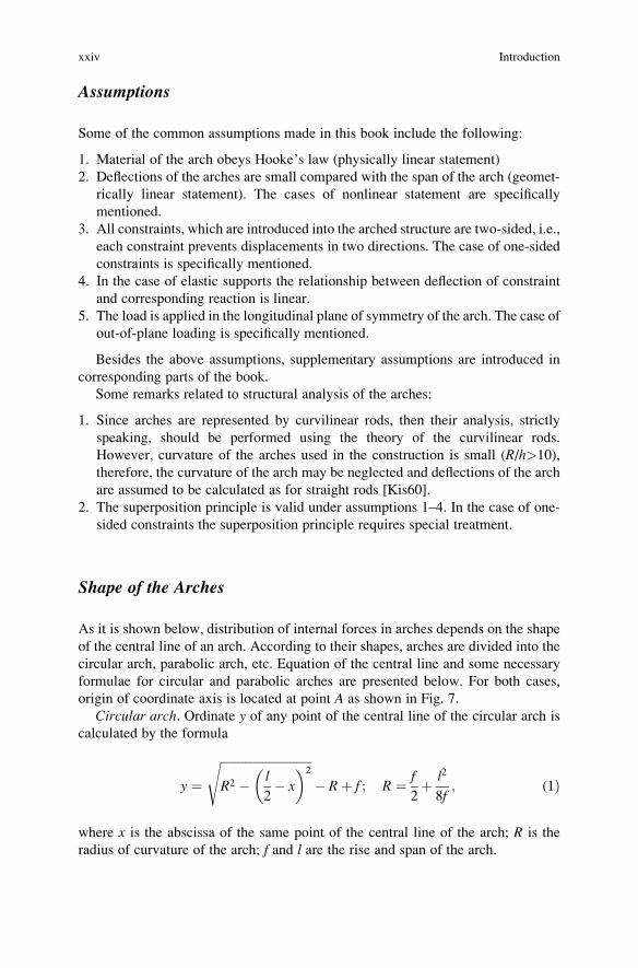
Shape of the Arches
As it is shown below, distribution of internal forces in arches depends on the shape
of the central line of an arch. According to their shapes, arches are divided into the
circular arch, parabolic arch, etc. Equation of the central line and some necessary
formulae for circular and parabolic arches are presented below. For both cases,
origin of coordinate axis is located at point A as shown in Fig. 7.
Circular arch. Ordinate y of any point of the central line of the circular arch is
calculated by the formula
y ¼ffiffiffiffiffiffiffiffiffiffiffiffiffiffiffiffiffiffiffiffiffiffiffiffiffiffiffiffiffiffiR2 � l
2� x
� �2s
� Rþ f ; R ¼ f
2þ l2
8f; (1Þ
where x is the abscissa of the same point of the central line of the arch; R is the
radius of curvature of the arch; f and l are the rise and span of the arch.
xxiv Introduction
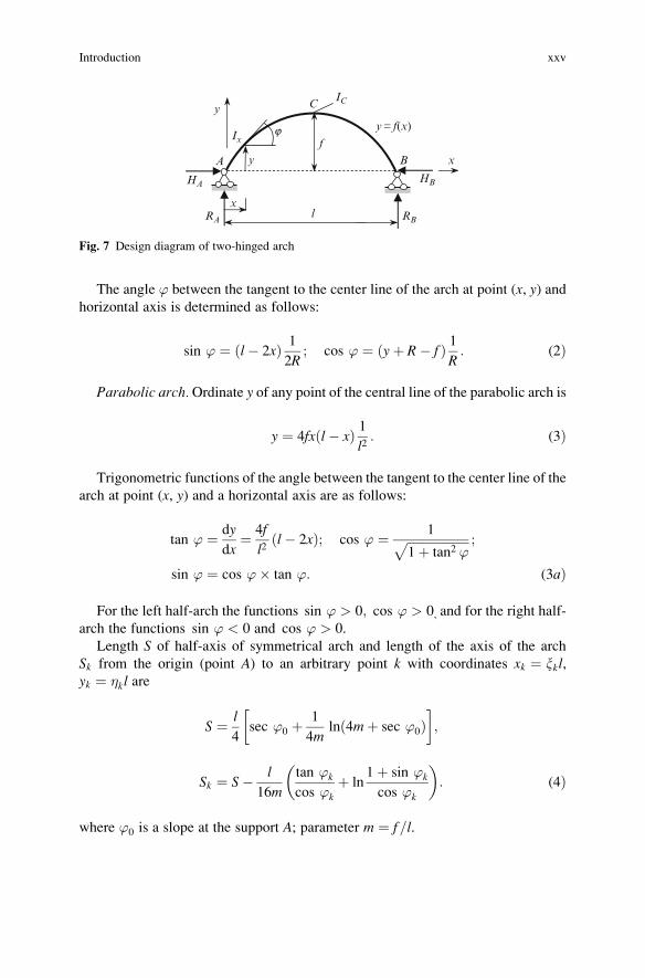
The angle ’ between the tangent to the center line of the arch at point (x, y) andhorizontal axis is determined as follows:
sin ’ ¼ ðl� 2xÞ 1
2R; cos ’ ¼ ðyþ R� f Þ 1
R: (2Þ
Parabolic arch.Ordinate y of any point of the central line of the parabolic arch is
y ¼ 4fxðl� xÞ 1l2: (3Þ
Trigonometric functions of the angle between the tangent to the center line of the
arch at point (x, y) and a horizontal axis are as follows:
tan ’ ¼ dy
dx¼ 4f
l2l� 2xð Þ; cos ’ ¼ 1ffiffiffiffiffiffiffiffiffiffiffiffiffiffiffiffiffiffiffiffi
1þ tan2 ’p ;
sin ’ ¼ cos ’� tan ’: (3aÞ
For the left half-arch the functions sin ’ > 0; cos ’ > 0, and for the right half-
arch the functions sin ’ < 0 and cos ’ > 0.
Length S of half-axis of symmetrical arch and length of the axis of the arch
Sk from the origin (point A) to an arbitrary point k with coordinates xk ¼ xkl,yk ¼ �kl are
S ¼ l
4sec ’0 þ
1
4mln 4mþ sec ’0ð Þ
� �;
Sk ¼ S� l
16m
tan ’k
cos ’k
þ ln1þ sin ’k
cos ’k
� �: (4Þ
where ’0 is a slope at the support A; parameter m ¼ f l= .
xA
C
l
f
B
y
HA HB
RA RB
x
y= f(x)Ix
IC
y
j
Fig. 7 Design diagram of two-hinged arch
Introduction xxv

Catenary arch. Ordinate y of any point of the central line of the catenary arch
as a function of load may be calculated by the formula which is presented in
Sect. 2.3.2.
More expressions y(x) for different arch shapes are presented in Tables A.1–A.5[Kar01].
Strictly speaking, the concept of arch shape includes not only equation of central
line as shown above, but also the law of flexural rigidity along the axis of the arch
[Kis60]. The flexural rigidity EI(x) may be constant or variable along the axis of the
arch depending on expected distribution of internal forces, requirements of a
constructive nature and asthetic considerations. Usually the variable rigidity of
the arch EI(x) expresses in terms of rigidity of the arch at crown, EIC, where E is
a modulus of elasticity, IC is a moment of inertia of a cross section at the crown C of
an arch. This will be considered in more details in Sect. 3.1.
Loads
Arches, as main structural components, are subject to a variety of loads depending
on the purpose of the arch and conditions of its operation.
For arches in public and industrial buildings the main loads are deadweight, live-
load, and snow. These loads act in the longitudinal plane of symmetry of the arch
and lead to in-plane bending. A significant load for arched structures is a wind
pressure. The wind leads to the positive and negative loads onto the arch.
A simplified scheme of the wind pressure is shown in Fig. 8.
In the case of a tall arch, the in-plane wind loads leads to significant internal
forces in the arch. If a tall arch has a small own weight, then the formation of the
negative reactions is possible; this dangerous phenomenon leads to the separation
of the arch from abutment.
Pressure of the wind, which is directed perpendicular to the plane of the arch,
leads to out-of-plane bending of the arch. These loads are absorbed by bracing
between arches.
A dangerous phenomenon is observed in the case of an arched cover with open
sides. Wind pressure, which is parallel to an open aperture, flows around them and
creates a vacuum inside. As a result, the positive pressure onto the arch increases
and suction decreases.
Positivepressure
Negative pressure (suction)
Wind
Fig. 8 Pressure of the wind on the surface of the arch
xxvi Introduction
For arched bridges the main loads, which lead to the in-plane bending of the
arch, are the following: deadweight, vertical loads from vehicles, and horizontal
load caused by their longitudinal deceleration. Also, in the case of a bridge with
curvature in the horizontal plane, one should take into account horizontal loads,
which are caused by moving vehicles in a curvilinear trajectory.
The settlement of supports may induce in-plane and out-of-plane bending. Out-
of-plane bending also arises by horizontal out-of-plane wind pressure, and seismic
loads. Asymmetric location of the load with respect to the longitudinal plane of
symmetry also leads to out-of-plane bending of the arch.
Some types of loads have a distinctly dynamic nature. Among them are seismic
loads, wind gusts, moving inertial loads and their deceleration, impacts of wheels
on the joints of rails on railway bridges. In the case of road bridges one should take
into account the roughness of their surface.
If the shell is reinforced with ribs and is immersed into a liquid, then the pressure
on the shell is transmitted on ribs and each rib can be considered as an arch due to a
uniformly distributed radial load.
Determination of loads on the arch and the consideration of all possible
combinations of loads is an important part of engineering analysis
Introduction xxvii


