Theoretical and Experimental Investigation of Plasma Antenna Characteristics
Scientia Iranica B (2021) 28(1), 291{304
Sharif University of TechnologyScientia Iranica
Transactions B: Mechanical Engineeringhttp://scientiairanica.sharif.edu
Theoretical and experimental investigation of designparameter e�ects on the slip phenomenon andperformance of a centrifugal compressor
S. Rajabpour, A. Hajilouy Benisi�, and M.T. Manzari
School of Mechanical Engineering, Sharif University of Technology, Tehran, P.O. Box 11155/8639, Iran.
Received 1 March 2019; received in revised form 28 August 2019; accepted 3 March 2020
KEYWORDSCentrifugalcompressor;Slip factor;CFD;Experimental test.
Abstract. Numerous studies have investigated driving equations used to predict theslip factor in centrifugal compressors so far. Inevitably, through these studies, the ow�eld characteristics have been simpli�ed and the e�ects of the related parameters havebeen neglected. The present study, experimentally and numerically, investigates the slipphenomenon in a speci�c centrifugal compressor with complex blade curves and splitterblades, considering the main e�ective parameters such as the number of blades, exit angle,etc. To this end, a three-dimensional simulation of the viscous ow �eld of the compressorvia an appropriate turbulence method was performed. In addition, an experimental studywas carried out at certain rotational speeds and mass ow rates of the slip factor. The e�ectsof the main parameters such as rotational speed, mass ow rate, blade number, blade exitangle, di�user design, and tip clearance on the slip phenomenon were studied. Furthermore,di�erent performance parameters such as pressure ratio and isentropic e�ciency with slipfactor were investigated. As observed, the slip factor increased upon an increase in bothrotational speed and ow rate. Moreover, changing the blade number from 6 to 9 at aconstant rotational speed and a mass ow rate increased the slip factor up to 27%.
© 2021 Sharif University of Technology. All rights reserved.
1. Introduction
Slip factor is a signi�cant performance parameter forcentrifugal compressors. It determines the capability ofa machine to transfer energy to the uid ow [1]. Thepressure ratio of centrifugal compressors is a functionof e�ciency and slip factor [2]. Therefore, obtainingaccurate information about the slip phenomenon isessential for an e�cient design. Di�erent elementsof the centrifugal compressor are usually individually
*. Corresponding author. Tel.: +98 21 66165512E-mail address: [email protected] (A. Hajilouy Benisi)
doi: 10.24200/sci.2020.53042.3040
designed and the slip factor is a measure of matchingthese components [3,4]. The uid entering the impelleris considered irrotational. In a rotating frame ofreference, a relative eddy rotating around the oppositedirection of the impeller is required to maintain anirrotational ow in the absolute frame. The blades donot direct the ow correctly due to the presence of thisrelative eddy and this is the basis of the slip [5].
Many e�orts have been made to develop a simpleequation to predict the slip factor. However, there areonly a few published papers in the literature that haveconsidered the e�ects of design parameters on the slipfactor of centrifugal compressors. Previous researchershave managed to derive a simple equation to predictthe slip factor based on experimental data. Stodola
292 S. Rajabpour et al./Scientia Iranica, Transactions B: Mechanical Engineering 28 (2021) 291{304
suggested Eq. (1) for slip factor (�) in centrifugalimpellers as a function of blade exit angle (�2) andthe number of blades (Z) [6]:
� = 1��� sin(�2)
Z
�60 < �2 < 70: (1)
The slip factor in this relation is de�ned in thefollowing:
� =C 0u2u2
+'2
tan(�2); (2)
where C 0u2, u2, and '2 are the tangential component
of ow velocity, blade speed, and ow factor at theimpeller exit, respectively.
Busemann (1928) revised some of previous equa-tions and analytically solved a two-dimensional inviscid ow �eld around the impeller [4]. He developed a set ofcurves to predict the slip factor as a function of severalparameters such as the number of blades, exit angle ofblades, and radius ratio.
Wislicenus (1947) showed that the accuracy ofequations depended on the working condition of thecompressor [7]. Studies on several radial impellers [8]led Stanitz to one of the most popular equations forthe slip factor in 1952 [9]:
� = 1� 0:63�Z
: (3)
At exit angles lower than 30 degrees with the numberof blades larger than 8, the results of the slip factorobtained using Eqs. (1) and (3) were close to Busemanncurves.
Wiesner (1967) developed an equation for the slipfactor, as shown in the following [4]:
� = 1�p
cos(�)Z0:7 : (4)
Simple equations were developed for the slip factorin centrifugal compressors by including more param-eters and evaluating the accuracy of these equationswith experimental data [3,10]. Such studies haveonly focused on the slip factor rather than the slipphenomenon. Researchers have also simpli�ed the ow�eld by assuming simple blade curves or neglecting thee�ects of other design parameters [3].
Whit�eld and Baines (1990) showed that theavailable equations for slip factor were not applicableto an optimum design since they did not includeenough parameters [2]. Then, Whit�eld presented ananalytical method based on the jet/wake model [11].Von Backstrorm (2006) developed an equation for theslip factor of a simple impeller as follows [12]:
� = 1� 1
1 +�
2 + 3 cos(�) (1�RR)Z2� cos(�)
� ; (5)
where \RR" is the impeller inner-to-outer radius ratio.
He expanded this analytical work by involving parame-ters such as radius ratio and blade shape and solidity inthe prediction of the slip factor [13]. The major draw-back of these analytical works is that they are limitedto speci�c simple geometries and simpli�cations [14].
A majority of recent studies on the slip phe-nomenon in centrifugal impellers have investigatedpumps [15,16] and considered some parameters such as ow rate, rotational speed, impeller exit angle, radiusratio, and blade geometry to evaluate the slip fac-tor [17,18]. Ghaderi et al. (2015) used a neural networkmethod to predict the slip factor obtained from a set ofexperimental data. This method accounts for the non-linearity of the relationship between parameters andthe slip factor [19].
Hung and Lou (2013) considered the e�ects of de-sign parameters on the slip phenomenon in a centrifugalcompressor [16] and concluded that more detailedstudies on the slip phenomenon were required sincemany questions have been left unanswered.
Moreover, the design of all elements of a cen-trifugal compressor and their interactions a�ects the ow slip [20,21]. However, to the best of the author'sknowledge, no published work has been found in theliterature including all these details. In this study, theslip factor in a centrifugal compressor was investigatedby considering the splitter blades in the impeller andvariable exit angles of the blade from hub to shroud.
2. De�nitions and formulation
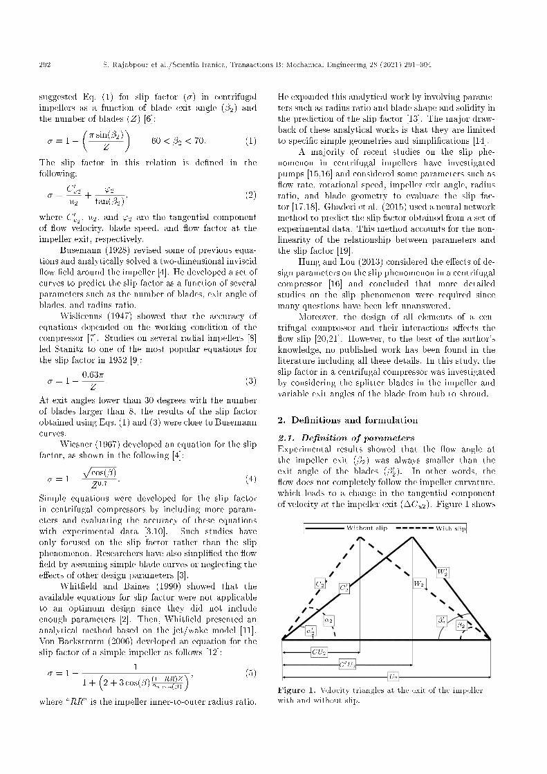
2.1. De�nition of parametersExperimental results showed that the ow angle atthe impeller exit (�2) was always smaller than theexit angle of the blades (�02). In other words, the ow does not completely follow the impeller curvature,which leads to a change in the tangential componentof velocity at the impeller exit (�Cu2). Figure 1 shows
Figure 1. Velocity triangles at the exit of the impellerwith and without slip.
S. Rajabpour et al./Scientia Iranica, Transactions B: Mechanical Engineering 28 (2021) 291{304 293
the velocity triangles at the impeller exit. The slipfactor (�) is de�ned as follows [22]:
� =Cu2
C 0u2: (6)
In this equation, the ow �eld is assumed two dimen-sional. In a real and three-dimensional ow condition,the slip factor varies from point to point; thus, it shouldbe used as an average equation while reporting a singlevalue, as shown in the following:
�� =R�d _mRd _m
: (7)
The present study de�nes the mass parameter, isen-tropic e�ciency, and pressure ratio as follows:
MP = _mpTt;ipt;i
; (8)
PR =Pt;oPt;i
; (9)
� =
�Pt;oPt;i
� �1 � 1
Tt;oTt;i � 1
: (10)
2.2. Speci�cations of the compressorThe compressor used in this research is a model4082 turbocharger compressor manufactured by Garretcompany. This compressor is installed in the testbed ofturbocharger laboratory at Sharif University of Tech-nology. The compressor geometry and performancespeci�cations are given in Table 1.
3. Experimental method
In this research, experimental investigations were car-ried out to understand the slip phenomenon better andevaluate the accuracy of numerical simulations. To thisend, the setup and facilities of the Turbocharger Lab
Table 1. Geometry and speci�cations of the compressorin BEP (Best E�ciency Point).
Parameter Value & unit
Number of blades
(including splitter blades)12
Blade angle, inlet 60 degree
Blade angle, exit 30{45 degree
Eye tip diameter 56 mm
Eye root diameter 22 mm
Overall diameter of the impeller 82 mm
Axial width of vaneless di�user 5.5 mm
Rotational speed 92000 rpm
Mass ow 0.287 kg/s
Pressure ratio 2.17
Isentropic e�ciency 0.85
Axial width of rotor outlet 41 mm
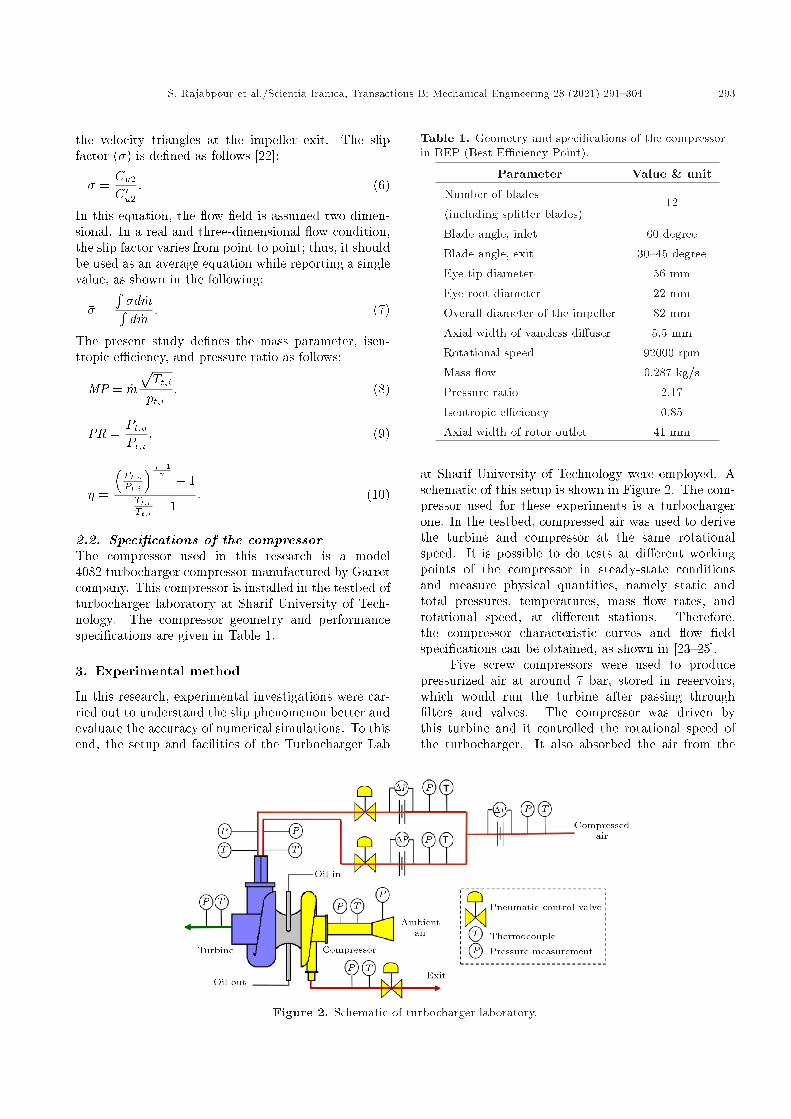
at Sharif University of Technology were employed. Aschematic of this setup is shown in Figure 2. The com-pressor used for these experiments is a turbochargerone. In the testbed, compressed air was used to derivethe turbine and compressor at the same rotationalspeed. It is possible to do tests at di�erent workingpoints of the compressor in steady-state conditionsand measure physical quantities, namely static andtotal pressures, temperatures, mass ow rates, androtational speed, at di�erent stations. Therefore,the compressor characteristic curves and ow �eldspeci�cations can be obtained, as shown in [23{25].
Five screw compressors were used to producepressurized air at around 7 bar, stored in reservoirs,which would run the turbine after passing through�lters and valves. The compressor was driven bythis turbine and it controlled the rotational speed ofthe turbocharger. It also absorbed the air from the
Figure 2. Schematic of turbocharger laboratory.

294 S. Rajabpour et al./Scientia Iranica, Transactions B: Mechanical Engineering 28 (2021) 291{304
ambiance through a bell mouth, used for measuring themass ow rate. The compressor tests were performed atseveral speeds of 40{92 krpm with at least 5 operatingpoints at each rotational speed and they were uniformlyspaced over a range of ow rates. Every test wasrepeated several times to ensure repeatability. Themass ow rates of both compressor and turbine werecontrolled with several electro-pneumatic valves. Totalpressures were sampled with pitot tubes and measuredwith pressure transducers at the inlet and outlet of thecompressor. Total temperatures were measured by Jtype thermocouples. A �ber optic sensor was used tomeasure the rotational speed of the turbocharger shaft.The required data were automatically obtained using adata acquisition system, saved on a PC, and processedusing suitable software packages.
Due to the errors in every experiment, identi�-cation and estimation of them are essential to specifythe reliability of the results. Standards such as PTC10 or PTC 19.1 describe correct methods for preparingthe laboratory, instrumentations, and thermodynamiccalculations [26,27]. In addition, PTC 19.2 and PTC19.3 introduce pressure and temperature measurementin detail [28,29]. The main sources of uncertaintyin this study are categorized into 5 groups: location,installation, calibration, device, and acquisition [30].By combining the e�ects of these errors, the total un-certainty in the desired parameters was calculated [31].
4. Simulation procedure
A steady-state 3D viscous commercial solver was em-ployed for ow �eld simulations. Flow domain wasdivided into four segments including inlet, impeller,di�user, and volute. For each segment, grids weregenerated according to their particular geometry. Forexample, there are blades in the impeller domain andthey are moving elements; thus, a dynamic grid isgenerated based on the blade geometry, as presentedin Figure 3.
The segregated method was used for the dis-cretization of momentum and energy equations due
Figure 3. Details of grid in the impeller.
to several advantages that it had in ow simulationof the centrifugal compressor convergence. Here, theSIMPLEC algorithm was utilized [32]. The ShearStress Transport (SST) turbulence method was alsoused, bene�ting from good accuracy of the k � !method and k � ! method near the walls and outsidethe boundary layer, respectively [33,34].
Boundary conditions of this simulation are totalpressure and total temperature at the inlet of thecompressor and mass ow at its outlet, as shown inFigure 4. Turbulence intensity for the inlet ow isassumed to be 5% [32]. Due to the steady state condi-tion in this study, the frozen rotor method was utilizedto facilitate the ow passage among the rotating andstationary parts of the compressor. This method enjoysa critical advantage, i.e., keeping the details of the ow.
Structured grids were taken into considerationin the inlet region and impeller. O-type and H-typegrids were used for the leading and trailing edges ofthe blades, respectively. The grids in the volute wereunstructured because of their complicated geometry,and those in the boundary layer were used for achievinghigher accuracy close to the walls of the volute, asshown in Figure 5.
The present study investigated how the numericalsolution was independent of the grid sizes. Theappropriate number of elements was found to be ap-proximately 3 million. The total number of grid cellswas 600000 for each passage of the impeller, 130000 forthe di�user, and 2.2 million for volute.
Figure 4. The computational domain.
Figure 5. Details of grid in the volute.
S. Rajabpour et al./Scientia Iranica, Transactions B: Mechanical Engineering 28 (2021) 291{304 295
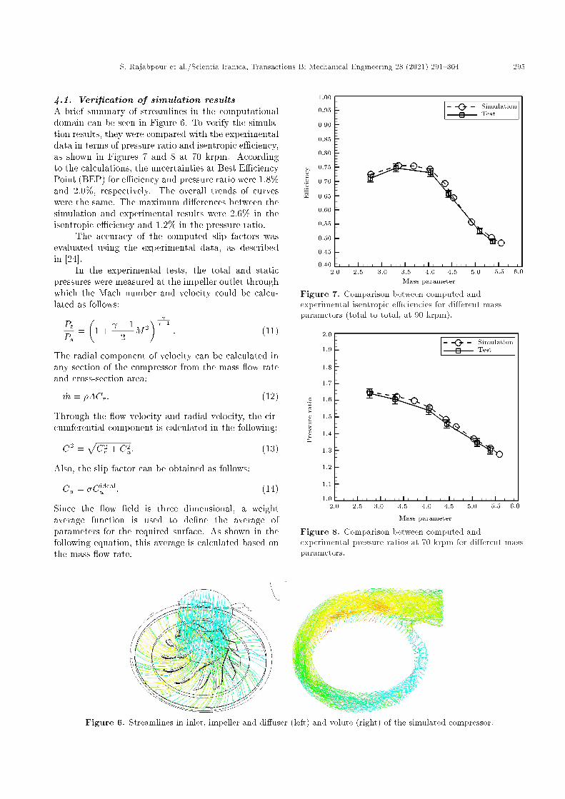
4.1. Veri�cation of simulation resultsA brief summary of streamlines in the computationaldomain can be seen in Figure 6. To verify the simula-tion results, they were compared with the experimentaldata in terms of pressure ratio and isentropic e�ciency,as shown in Figures 7 and 8 at 70 krpm. Accordingto the calculations, the uncertainties at Best E�ciencyPoint (BEP) for e�ciency and pressure ratio were 1.8%and 2.0%, respectively. The overall trends of curveswere the same. The maximum di�erences between thesimulation and experimental results were 2.6% in theisentropic e�ciency and 1.2% in the pressure ratio.
The accuracy of the computed slip factors wasevaluated using the experimental data, as describedin [24].
In the experimental tests, the total and staticpressures were measured at the impeller outlet throughwhich the Mach number and velocity could be calcu-lated as follows:
PtPs
=�
1 + � 1
2M2� �1
: (11)
The radial component of velocity can be calculated inany section of the compressor from the mass ow rateand cross-section area:
_m = �ACr: (12)
Through the ow velocity and radial velocity, the cir-cumferential component is calculated in the following:
C2 =pC2r + C2
u: (13)
Also, the slip factor can be obtained as follows:
Cu = �C idealu : (14)
Since the ow �eld is three dimensional, a weightaverage function is used to de�ne the average ofparameters for the required surface. As shown in thefollowing equation, this average is calculated based onthe mass ow rate:
Figure 7. Comparison between computed andexperimental isentropic e�ciencies for di�erent massparameters (total to total, at 90 krpm).
Figure 8. Comparison between computed andexperimental pressure ratios at 70 krpm for di�erent massparameters.
Figure 6. Streamlines in inlet, impeller and di�user (left) and volute (right) of the simulated compressor.

296 S. Rajabpour et al./Scientia Iranica, Transactions B: Mechanical Engineering 28 (2021) 291{304
Figure 9. The surface of slip investigations.
�' =R'd _mRd _m
Discritization�����������!P' _mP
_m: (15)
This equation is used for the outlet of the compressorto determine total temperature and total pressureand for the exit surface of the impeller to determinecircumferential and radial components of velocity. Theexit surface of the impeller is shown in Figure 9.
After measuring the total temperature and totalpressure at the outlet of the compressor, the e�ciencyand pressure ratios can be calculated using Eqs. (9)and (10), respectively. Moreover, by determining thecircumferential and radial components of velocity atthe exit surface of the impeller and using the rotationalspeed of compressor and radius of the exit surface, theslip factor and ow angle were respectively calculated:
� =�Cur!
; (16)
and:
� = tan�1�Cu�Cr: (17)
According to Figure 10, the trends of the simulationresults and experimental data are the same and themaximum di�erence is 3.4% at 60 krpm. Therefore,it can be concluded that the obtained accuracy of thesimulation while predicting the ow �eld and slip factorwas acceptable.
4.2. Evaluation of the slip factor equationsTwo problems may arise while using the slip factorequations discussed in the Introduction. Firstly, mostof these equations were derived for impellers withoutsplitter blades, which is not the case in this study.Secondly, the exit angle of blades in these equations isgenerally regarded as a constant, while in the presentstudy, the exit angle changes from hub to shroud.Figure 11 shows a comparison between the slip factorscalculated using these equations and the experimentaldata obtained in this study. As observed, only Stodolaand Stanitz equations yielded acceptable results, withdi�erences of 3% and 5%, respectively, near BEP of thecompressor. Far from BEP, all equations would yieldquite di�erent results.
Figure 10. Comparison between computed andexperimental slip factors at 50 and 60 krpm.
Figure 11. Comparing the slip factors obtained by theequations proposed in the literature with experimentaldata (red line speci�es Best E�ciency Point (BEP) mass ow rate).
5. Slip factor and design parameters
In this section, the e�ects of some design parameterson the slip factor of the centrifugal compressor areinvestigated. At every step of this study, the slipfactor and ow angle are separately determined. Theseparameters are calculated on the exit surface of theimpeller, as presented in Figure 9.
5.1. E�ects of rotational speed and mass owrate
Although the e�ects of rotational speeds and mass owrates on the slip factor have been studied before [11],
S. Rajabpour et al./Scientia Iranica, Transactions B: Mechanical Engineering 28 (2021) 291{304 297
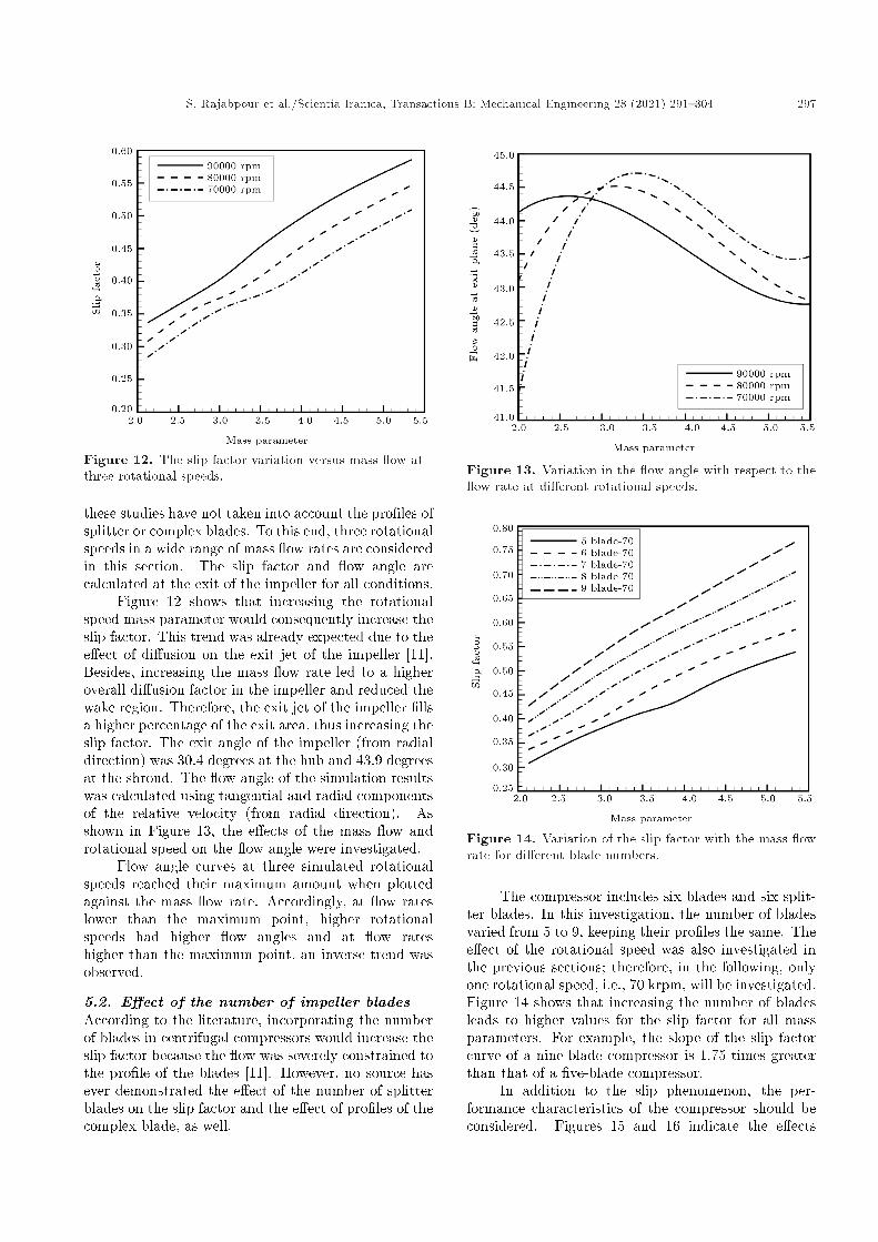
Figure 12. The slip factor variation versus mass ow atthree rotational speeds.
these studies have not taken into account the pro�les ofsplitter or complex blades. To this end, three rotationalspeeds in a wide range of mass ow rates are consideredin this section. The slip factor and ow angle arecalculated at the exit of the impeller for all conditions.
Figure 12 shows that increasing the rotationalspeed mass parameter would consequently increase theslip factor. This trend was already expected due to thee�ect of di�usion on the exit jet of the impeller [11].Besides, increasing the mass ow rate led to a higheroverall di�usion factor in the impeller and reduced thewake region. Therefore, the exit jet of the impeller �llsa higher percentage of the exit area, thus increasing theslip factor. The exit angle of the impeller (from radialdirection) was 30.4 degrees at the hub and 43.9 degreesat the shroud. The ow angle of the simulation resultswas calculated using tangential and radial componentsof the relative velocity (from radial direction). Asshown in Figure 13, the e�ects of the mass ow androtational speed on the ow angle were investigated.
Flow angle curves at three simulated rotationalspeeds reached their maximum amount when plottedagainst the mass ow rate. Accordingly, at ow rateslower than the maximum point, higher rotationalspeeds had higher ow angles and at ow rateshigher than the maximum point, an inverse trend wasobserved.
5.2. E�ect of the number of impeller bladesAccording to the literature, incorporating the numberof blades in centrifugal compressors would increase theslip factor because the ow was severely constrained tothe pro�le of the blades [11]. However, no source hasever demonstrated the e�ect of the number of splitterblades on the slip factor and the e�ect of pro�les of thecomplex blade, as well.
Figure 13. Variation in the ow angle with respect to the ow rate at di�erent rotational speeds.
Figure 14. Variation of the slip factor with the mass owrate for di�erent blade numbers.
The compressor includes six blades and six split-ter blades. In this investigation, the number of bladesvaried from 5 to 9, keeping their pro�les the same. Thee�ect of the rotational speed was also investigated inthe previous sections; therefore, in the following, onlyone rotational speed, i.e., 70 krpm, will be investigated.Figure 14 shows that increasing the number of bladesleads to higher values for the slip factor for all massparameters. For example, the slope of the slip factorcurve of a nine-blade compressor is 1.75 times greaterthan that of a �ve-blade compressor.
In addition to the slip phenomenon, the per-formance characteristics of the compressor should beconsidered. Figures 15 and 16 indicate the e�ects

298 S. Rajabpour et al./Scientia Iranica, Transactions B: Mechanical Engineering 28 (2021) 291{304
Figure 15. Variation of isentropic e�ciency with the owrate for di�erent number of blades.
Figure 16. Variation of pressure ratio di�erence with the ow rate for di�erent number of blades.
of the number of blades on the isentropic e�ciencyand pressure ratio, respectively. In other words, atsmall values of mass ow rate, the larger number ofblades would increase the e�ciency; however, at highervalues, it led to a signi�cant drop in e�ciency. Thisoccurs because increasing the number of blades leadsto greater blockage of the ow path and this blockagebecomes critical at higher ow rates because there isnot enough space for ow to pass the impeller. Thee�ect of the number of blades on the pressure ratio issimilar to the e�ciency.
Another comparison was made with emphasison the e�ect of replacing the splitter blades by themain blades. Therefore, another design of the originalcompressor was investigated. The compressor used inthis design has 12 main blades without any splitter.
Figure 17. Variation of slip factor with the mass owrate in cases with and without splitters.
Figure 18. Variation of the blade exit angle from hub toshroud in the base design.
Figure 17 shows that at 70 krpm, the slip factorin the new impeller is lower than that in the originalone. This result corresponds to the ow �eld in theimpeller and e�ect of the starting point of the splitterblades [35].
5.3. E�ects of blade exit angleTo investigate the e�ect of the exit angle of the blade,the blade pro�le was approximated by a spline functionwith �nite control points. By changing the last controlpoint, the exit angle varied, too; however, the overallpro�le remains the same. This procedure provides newblades with a smooth shape.
In the present compressor, the impeller exit angleis not constant and varies from 30 degrees at the hubto 44 degrees at the shroud, as shown in Figure 18.

S. Rajabpour et al./Scientia Iranica, Transactions B: Mechanical Engineering 28 (2021) 291{304 299
Figure 19. Variation of slip factor with the ow rate atdi�erent hub exit angles.
Figure 20. Variation of ow deviation with the ow rateat di�erent exit angles at the hub.
Therefore, the study of the exit angle of the blade wasperformed for two separate cases:
1. Exit angle variations at hub;
2. Exit angle variations at shroud.
Figure 19 shows the computed slip factors as theexit angle varies at the hub. In other words, the higherthe exit angle is, the higher the slip factor becomes. Inaddition, a similar trend was observed in all cases.
Figure 20 shows the e�ects of the variation in theexit angle of the blade at the hub on ow deviations.As observed, the higher the exit angles are, the lowerthe ow deviations will be.
Simulation results showed the negligible e�ect of
Figure 21. Variation of pressure ratio with the ow rateat di�erent hub exit angles (at 70 krpm).
Figure 22. Variation of slip factor with the ow rate atdi�erent shroud exit angles.
this parameter on the isentropic e�ciency. Accordingto Figure 21, higher exit angles of the blade at hublead to a greater decrease in the pressure ratio, whichis intensi�ed at higher ow rates.
A similar study was carried out by considering theexit angle of the blades at the shroud varying from 35to 55 degrees. Figure 22 shows that higher exit anglesat the shroud increase the slip factor, showing similarresults to those obtained at the hub. The trend ofvariation in the ow angle at the shroud is also similarto that at the hub, as shown in Figure 23.
A brief review of the performance parameters ofthe compressor shows that the exit angle variations(hub and shroud) did not signi�cantly change thepressure ratio and isentropic e�ciency; however, at exit

300 S. Rajabpour et al./Scientia Iranica, Transactions B: Mechanical Engineering 28 (2021) 291{304
Figure 23. Variation of ow deviation with the ow rateat di�erent shroud exit angles.
Figure 24. The schematic of the ow passage ofcompressor.
angles of the blade below the values of the originaldesign, an 8% drop in the pressure ratio was observed.
Furthermore, higher exit angles increased the slipfactor and decreased ow deviation, indicating thatcentrifugal compressors performed di�erently from thepumps [15].
5.4. E�ects of the di�user design andconnector segment
To the best of our knowledge, there are not anyavailable sources or research in the open literature onthe e�ects of di�user design on the slip phenomenon,and most of the investigations are limited to theimpeller section. In this research, two variations ofthe compressor di�user were investigated. In the �rstcase, \D1", the di�user width varied from 4.27 to3.50 mm; in the second case, \D2", the shroud pro�le
Figure 25. Variation of slip factor with the ow rate anddi�user design.
Figure 26. Variations in the ow angle with the owangle and di�user design.
of the connector segment was modi�ed, see Figure 24.The original pro�le of the connector segment at theshroud includes two concavities and is constrained tobe tangent to the impeller outlet and di�user inlet. Thesecond variation is a Spline curve that �ts with oneconcavity and is only constrained to be tangent to thedi�user inlet.
Simulation results in Figure 25 show that thesevariations change the slip factor slightly. In the �rstcase, the trend of ow angle remained similar to theinitial design with its value decreasing. In the secondcase, its trend changed slightly and the ow deviationincreased, see Figure 26. Therefore, it was found thatthe design of the di�user and the connector segmenta�ected the slip phenomenon.
S. Rajabpour et al./Scientia Iranica, Transactions B: Mechanical Engineering 28 (2021) 291{304 301
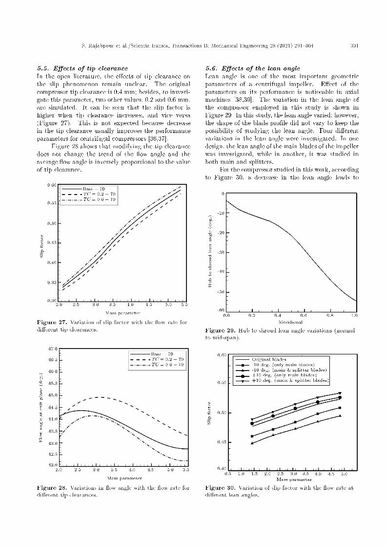
5.5. E�ects of tip clearanceIn the open literature, the e�ects of tip clearance onthe slip phenomenon remain unclear. The originalcompressor tip clearance is 0.4 mm; besides, to investi-gate this parameter, two other values, 0.2 and 0.6 mm,are simulated. It can be seen that the slip factor ishigher when tip clearance increases, and vice versa(Figure 27). This is not expected because decreasein the tip clearance usually improves the performanceparameters for centrifugal compressors [36,37].
Figure 28 shows that modifying the tip clearancedoes not change the trend of the ow angle and theaverage ow angle is inversely proportional to the valueof tip clearance.
Figure 27. Variation of slip factor with the ow rate fordi�erent tip clearances.
Figure 28. Variations in ow angle with the ow rate fordi�erent tip clearances.
5.6. E�ects of the lean angleLean angle is one of the most important geometricparameters of a centrifugal impeller. E�ect of theparameters on its performance is noticeable in axialmachines [38,39]. The variation in the lean angle ofthe compressor employed in this study is shown inFigure 29. In this study, the lean angle varied; however,the shape of the blade pro�le did not vary to keep thepossibility of studying the lean angle. Four di�erentvariations in the lean angle were investigated. In onedesign, the lean angle of the main blades of the impellerwas investigated, while in another, it was studied inboth main and splitters.
For the compressor studied in this work, accordingto Figure 30, a decrease in the lean angle leads to
Figure 29. Hub to shroud lean angle variations (normalto mid-span).
Figure 30. Variation of slip factor with the ow rate atdi�erent lean angles.
302 S. Rajabpour et al./Scientia Iranica, Transactions B: Mechanical Engineering 28 (2021) 291{304
lower slip factors, and vice versa, and also changingthe lean angle of the splitter blades (favorable to themain blades) intensi�es this e�ect.
6. Conclusions
The main objective of the present study was to in-vestigate the e�ects of design parameters on the slipphenomenon in centrifugal compressors. To this end,one turbocharger compressor was selected on whichnumerical and experimental studies were performed.The slip factor, isentropic e�ciency, and pressure ratioof the compressor were experimentally obtained. Themaximum di�erences of the simulation results obtainedfrom the experimental data were 1.2, 2.6, and 3.4%,thus con�rming the accuracy of the simulation method.The slip factor for the compressor with some of themost accepted relations was also predicted and at theBest E�ciency Point (BEP) of the original compressor,the equation developed by Stodola showed the highestaccuracy with 1.5% error; however, none of them wasprecise enough for other working ranges.
Some of the design parameters of the centrifugalcompressor were studied and the results are summa-rized below:
1. Increasing the rotational speed and mass ow rateof the compressor led to higher slip factors at 9%,on average, for a 10 krpm increase in speed. At aconstant rotational speed, the ow angle at the exitof the impeller reached the maximum point as themass ow rate changed;
2. Upon increasing the number of the blades of animpeller, the slip factor increased by 10{14% pereach blade addition and the ow deviation at theexit of the impeller was consequently reduced.However, it caused a 0.5% decrease in the e�ciencyof the compressor in di�erent mass ows;
3. Increasing the exit angle of the blades led to ahigher slip factor and lower ow deviation at theexit of the impeller; however, it did not change thetrend of the slip factor. On average, a ten-degreeincrease in this parameter led to 8% and a �ve-degree increase in the slip factor and a decrease inlow deviation, respectively;
4. It was shown that the width and pro�le of di�userand connector segment between the impeller anddi�user slightly in uenced the slip factor. Besides,these parameters a�ected the exit ow angle con-siderably;
5. Increasing the tip clearance of the compressorimpeller within a limited range of 0.2 mm hada direct relationship with the slip factor. Thedi�erence between slip factors of the new and
original compressors remained almost constant atthe investigated mass ow interval;
6. Increasing the lean angle of impeller blades led to5% higher values of the slip factor.
Acknowledgement
The authors gratefully acknowledge the support pro-vided by the Research O�ce of Sharif University ofTechnology and the technical assistance of the Tur-bocharger Laboratory sta�.
Nomenclature
C Velocity (m/s)_m Mass ow rate (kg/s)P Pressure (Pa)T Temperature (K)u Blade speed (m/s)Z Number of blades� Exit angle (degree)� Slip factor' Flow factor
Subscripts
2 Exit of impelleri Inlett Stagnationo Outletu Tangential componentr Radial component
Abbreviations
BEP Best E�ciency PointCFD Computational Fluid DynamicsMP Mass ParameterRR Radius Ratio (impeller inner-to-outer
radius ratio)
References
1. Caridad, A.J. and Kenyery, F. \Slip factor for cen-trifugal impellers under single and two-phase owconditions", Journal of Fluids Engineering, 127, pp.317{321 (2005).
2. Whit�eld, A. and Baines, N., Design of Radial Turbo-machines, Harlow: Longman Scienti�c and Technical,pp. 83{134 (1990).
3. Ball, A.G., Bell, A.H., and Mann, L.B. \The develop-ment of the Chrysler automotive centrifugal compres-sor", In SAE International Congress And Expositionof Automotive Engineering (1961).
S. Rajabpour et al./Scientia Iranica, Transactions B: Mechanical Engineering 28 (2021) 291{304 303
4. Wiesner, F.J. \A review of slip factors for centrifugalimpellers", Journal of Engineering for Power, 89(4),pp. 558{566 (1967).
5. Aungier, R.H., Centrifugal Compressor: A Strategy forAerodynamics Design and Analysis, New York, ASMEPress (2000).
6. Stodola, A., Steam and Gas Turbines, New York,McGraw-Hill (1927).
7. Wislicenus, F.G., Fluid Mechanics of Turbomachinery,New York, McGraw-Hill (1947).
8. Sheets, H.E. \The ow through centrifugal compres-sors and pumps", In Trans. Amer. Soc. Mech. Engrs,72, p. 1009 (1950).
9. Stanitz, D.J. \Some theoretical aerodynamic investiga-tions of impellers in radial and mixed- ow centrifugalcompressors", In ASME, Cleveland, Ohio (1952).
10. Zhang, Y.L., Zhu, Z.C., Dou, H.S., Cui, B.L., Li,Y., and Xiao, J.J. \A method to determine theslip factor of centrifugal pumps through experiment",International Journal of Turbo & Jet-Engines, 32(1),pp. 59{64 (2015).
11. Whit�eld, A. \Slip factor of a centrifugal compressorand its variation with ow rate", Proceedings of theInstitution of Mechanical Engineers, 188, pp. 415{421(1974).
12. Von Backstrom, T. \A compact equation for the pre-diction of eddy-induced slip in centrifugal impellers",IMechE Part A: J. Power and Energy, 220(8), pp.911{915 (2006).
13. Von Backstrom, T. \A uni�ed correlation for slip factorin centrifugal impellers", Journal of Turbomachinery,128(1), pp. 1{10 (2006).
14. Ji, C., Zou, J., and Fu, X. \A new correlation for slipfactor in radial and mixed- ow impellers", Journal ofPower and Energy, 225(1), pp. 114{119 (2010).
15. Elsheshtawy, A. \Numerical study of slip factor incentrifugal pumps and study factors a�ecting its per-formance", In International Conference on MechanicalEngineering and Material Science (2012).
16. Hung, J. and Lou, K. \Numerical investigations of slipphenomena in centrifugal compressor impellers", TurboJet-Engines, 30(1), pp. 123{132 (2013).
17. Xuwen, Q., Japikse, D., and Zhai, J. \Analysis andvalidation of a uni�ed slip factor model for impellersat design and o�-design conditions", J. Turbomach.,133(4), 041018 (Oct. 2011).https://doi.org/10.1115/1.4003022
18. Ntoko, N. \A dynamical basis for slip in centrifugalimpellers", IMechE: Power and Energy, 226(5), pp.706{711 (2012).
19. Ghaderi, M., Naja�, A., and Nourbakhsh, A. \Improv-ing slip factor prediction for centrifugal pumps usingarti�cial neural networks", IMechE Part A: Power andEnergy, 229(4), pp. 431{438 (2015).https://doi.org/10.1177/0957650915580884
20. Plfeiderer, C.F., Die Kreiselpumpen f�ur Fl�ussigkeitenund Gase, Berlin: Springer (1961).
21. Dean, C.R. \On the unresolved uid dynamics of thecentrifugal compressor", Adv Centrifugal Compressors,ASME Special Publication, pp. 1{55 (1971).
22. Van den Braembussche, R., Design and Analysis ofCentrifugal Compressors, von Karman Institute, Bel-gium: ASME Press and John Wiley & Sons Ltd (2019).
23. Hajilouy Benisi, A., Rad, M., and Shahhosseini, M.R.\Flow and performance characteristic of twin-entryradial turbine under full and extreme partial admissionconditions", Scientia Iranica: Mechanical Engineering,79, pp. 1127{1143 (2003).
24. Doost Mohamadi, A., Hajilouy Benisi, A., and Mo-jaddam, M. \Experimental & numerical investigationof losses in centrifugal compressor components", InASME: Turbine Technical Conference and Exposition,San Antonio, Texas (2013).
25. Mojaddam, M. and Hajilouy-Benisi, A. \Experimentaland numerical ow �eld investigation through twotypes of radial ow compressor volutes", ExperimentalThermal and Fluid Science, 78, pp. 137{146 (2016).
26. Performance test code for compressors and exhausters,ASME (1997).
27. Test uncertainty, ASME (2013).
28. Pressure measurement: Instruments and apparatussupplement, ASME (2010).
29. PTC 19.3 TW thermowells, ASME (2016).
30. Brun, K. and Kurz, R. \Measurement uncertaintiesencountered during gas turbine driven compressor �eldtesting", Journal of Engineering for Gas Turbines andPower, 123, pp. 62{69 (2001).
31. Nakra, B.C. and Chaudhry, K.K., Instrumentation,Measurement And Analysis, New Delhi, McGraw-Hill(2003).
32. Mojaddam, M., Hajilouy Benisi, A., and Movahhedy,M. \Optimal design of the volute for a turbochargerradial ow compressor", In ASME: Turbine TechnicalConference and Exposition, D�usseldorf (2014).
33. Versteeg, H. and Malalasekera, W., An Introduction toComputational Fluid Dynamics: The Finite VolumeMethod, 2nd Edition, Harlow, Longman Scienti�c &Technical (2007).
34. Rodrigues, T.T. \Tubulence modelling evaluation forreciprocating compressor simulation", In InternationalCompressor Engineering Conference, Purdue Univer-sity (2014).
35. Moussavi, S.A., Hajilouy Benisi, A., and Durali, M.\E�ect of splitter leading edge location on performanceof an automotive turbocharger compressor", Energy,123, pp. 511{520 (2017).
36. Kim, C., Lee, H., Yang, J., Son, C., and Hwang, Y.\Study on the performance of a centrifugal compres-sor considering running tip clearance", InternationalJournal of Refrigeration, 65, pp. 92{102 (2016).

304 S. Rajabpour et al./Scientia Iranica, Transactions B: Mechanical Engineering 28 (2021) 291{304
37. Galindo, J., Tiseira, A., Navarro, R., and L�opez, M.A.\In uence of tip clearance on ow behavior and noisegeneration of centrifugal compressors in near-surgeconditions", International Journal of Heat and FluidFlow, 52, pp. 129{139 (2015).
38. Zhang, C., Jun, H., and Zhiqiang, W. \Three-dimensional compressor blading design improvementsin low-speed model testing", Aerospace Science andTechnology, 63, pp. 179{190 (2016).
39. Asgarshamsi A., Hajilouy Benisi A., Assempour A.,and Pourfarzaneh, H. \Multi-objective optimization oflean and sweep angles for stator and rotor blades ofan axial turbine", Proc IMechE Part G: J. AerospaceEngineering, 229(5), pp. 906{916 (2015).
Biographies
Shahram Rajabpour received his BS (2011) andMS degrees (2013) in Mechanical Engineering with aminor in Energy Conversion. He is currently a PhDCandidate at Sharif University of Technology in the�eld of turbomachines. His studies are focused on theexperimental tests, CFD methods and simulation, andoptimization and a new design method for centrifugalcompressors.
Ali Hajilouy Benisi received his PhD degree fromMechanical Engineering Department of Imperial Col-lege at the University of London, 1993. He was afaculty member at the Institute of Water and Energyand since 1978, he has been a faculty member in the
School of Mechanical Engineering at Sharif Universityof Technology (SUT). He served as the Director ofthe Fluid Mechanics Lab (1993{1995), Founder andDirector of the Turbocharger Lab (1993), Turbocharg-ing Lab (2000), and Gas Turbine Lab (2008) in theSchool of Mechanical Engineering of Sharif Universityof Technology. His research interests are experimentaland theoretical investigations of turbochargers, tur-bocharging, and gas turbines.
Mehrdad T. Manzari received his PhD degree fromthe University of Wales Swansea in 1996. He hasbeen a Professor of Mechanical Engineering at SharifUniversity of Technology since 2010. He was theDirector of Thermo-Fluid Group (2007{2009), Directorof Center of Excellence in Energy Conversion (2007{2009), and Director of Graduate Studies (2005{2007)in School of Mechanical Engineering of Sharif Uni-versity of Technology. He is the winner of the MostCommended Paper prize of MCB Publishers (1999& 2007) and Finalist of the 9th R.J. Melosh MedalCompetition in USA (1997). His research interests aremultiphase ows in porous media with applications inhydrocarbon reservoirs, simulation of uid ow andheat transfer in manufacturing processes, uid owand heat transfer in micro-electro-mechanical-systems,non-Newtonian uid ows, computational methods inengineering, smoothed particle hydrodynamics with en-gineering applications, high performance, and parallelcomputing.