Theoretical Analysis of New Regenerative Vapour Compression … · 2017-07-22 · vapour compresses...
6
International Journal of Science and Research (IJSR) ISSN (Online): 2319-7064 Index Copernicus Value (2013): 6.14 | Impact Factor (2015): 6.391 Volume 5 Issue 5, May 2016 www.ijsr.net Licensed Under Creative Commons Attribution CC BY Theoretical Analysis of New Regenerative Vapour Compression System Using Ejector as Second Stage of Compression Shobhit Mishra 1 , Nomendra Tomar 2 1 Scholar, Masters Degree, Thermal Engineering in Department of Mechanical Engineering, Jamia Millia Islamia, Delhi (India) 2 Assistant Professor, Mechanical Engineering Department, IIMT, Meerut, UP, (India) Abstract: This paper presents a detailed theoretical analysis of regenerative vapour compression refrigeration cycle with ejector as second stage of compression. The basic purpose of using ejector, is to utilize the regenerative use of potential energy of ejector two phase expansion flow which would otherwise be lost in expansion valve. First stage of compression is achieved by compressor, in which only vapour compresses to 50-60% of the final pressure, while second stage of compression is achieved by a jet device (ejector) using internal potential energy of the working fluid flow. By this arrangement work input to compressor is reduced significantly, resulting an increase in COP of the system as compared to traditional cycle. A mathematical computational model is developed in the equation window of engineering equation solver(EES) for calculating different parameters such as, compressor work, work of pump, refrigerating capacity and COP of the new regenerative cycle using new generation refrigerant HFO-1234yf as compared to R-134a. Keywords: Ejector, COP, HFO-1234yf, R-134a, New Regenerative Cycle 1. Introduction Refrigeration and air-conditioning is a science of producing low temperature as compared to surroundings, since low temperature are maintained continuously it must run on a cycle. Vapour compression refrigeration system found wide application in MAC(mobile air conditioning) and stationary refrigeration applications. there are various means to increase the performance of the cycle and to increase COP such as to utilize the liquid vapour heat exchanger in vapour refrigeration system[ ]. but the main drawback is that the refrigerant at the compressor outlet is at high temperature (usually 80-110°C for R-134a); thus a large amount of energy must be rejected by the condenser to the environment. this waste heat can be utilized to increase the refrigeration performance of the system because improved system performance will reduce energy consumption as well as green house gases emissions. An ejector cooling system driven by low-grade heat energy can effectively use the waste heat to improve the system COP. An ejector based cooling system offers several advantages, such as no moving parts in the ejector, efficient utilization of the waste heat from the condenser of VC system and low cost. The study of refrigerant (CFCs, HCFCs and HFCs) ejectors for air- conditioning or refrigeration applications started in the mid- 1950s for utilizing low-grade energy such as solar or waste heat energy as the heat source. The operation of a gas-to-gas or vapor-to-vapor ejector results mainly from the gas- dynamic effect and the momentum exchange of two gaseous streams (primary and secondary or entrained streams) inside the ejector. Two choking phenomena exist in the ejector performance one in the primary flow through the nozzle and the other in the entrained or suction flow. The entrained flow rate or the entrainment ratio (entrained-to-primary flow ratio v = m_ s/m_ p) of an ejector is affected by many factors. The physical phenomena involve supersonic flow, shock interactions, and turbulent mixing of two streams inside the ejector enclosure. It is so complicated that the design of an ejector to date still heavily relies on trials-and-errors methods although a number of gas-dynamic theories for ejector analysis were developed by several researchers. 2. Literature Review Many theories and experiments have been done to reduce the power consumption and increase the COP of the vapor compression refrigeration system. There are so many methods to increase the COP of the vapor compression system introducing the ejector is one of them. There are some theories and experiments which I reviewed for my study as follws: Mark J. Bergander [1] studied a new regenerative refrigeration vapour compression system using R-22 as a refrigerant then he finds that there is an increase in COP of system and this increase is about 18% as compared with conventional system. Kairouni L. et al. [2] developed a improved cooling cycle for a conventional multi-evaporator simple compression system utilizing ejector for vapour pre compression is analyzed. The ejector increase the refrigeration cycle consists of multi evaporators. The COP of novel cycle is better than the conventional system. Arbel and Sokolov [3] presented a theoretical study of a solar driven combined VCR-VER using R-142b as a working fluid. The study compared the performance of the system with previous studies developed by Sokolov, where R-113 was used. They showed out not only technical but also ecological improvements by using R-142b. At this time use of R-113 is prohibited. Jialin yu and Huazhao, (2007) [4] investigated a naval auto cascade refrigeration cycle with an ejector. The ejector is used to recover the some available work to increase the compression suction pressure this enables the compressor to operate at lower pressure ratio, which in turn improves the cycle efficiency. In this study they use the refrigerant as a mixture of R-23/R-134a. In this study they operated at condenser pressure of 40°C, the evaporator inlet temperature Paper ID: NOV164060 2515
Transcript of Theoretical Analysis of New Regenerative Vapour Compression … · 2017-07-22 · vapour compresses...
International Journal of Science and Research (IJSR) ISSN (Online): 2319-7064
Index Copernicus Value (2013): 6.14 | Impact Factor (2015): 6.391
Volume 5 Issue 5, May 2016
www.ijsr.net Licensed Under Creative Commons Attribution CC BY
Theoretical Analysis of New Regenerative Vapour
Compression System Using Ejector as Second Stage
of Compression
Shobhit Mishra1, Nomendra Tomar
2
1Scholar, Masters Degree, Thermal Engineering in Department of Mechanical Engineering, Jamia Millia Islamia, Delhi (India)
2Assistant Professor, Mechanical Engineering Department, IIMT, Meerut, UP, (India)
Abstract: This paper presents a detailed theoretical analysis of regenerative vapour compression refrigeration cycle with ejector as
second stage of compression. The basic purpose of using ejector, is to utilize the regenerative use of potential energy of ejector two phase
expansion flow which would otherwise be lost in expansion valve. First stage of compression is achieved by compressor, in which only
vapour compresses to 50-60% of the final pressure, while second stage of compression is achieved by a jet device (ejector) using internal
potential energy of the working fluid flow. By this arrangement work input to compressor is reduced significantly, resulting an increase
in COP of the system as compared to traditional cycle. A mathematical computational model is developed in the equation window of
engineering equation solver(EES) for calculating different parameters such as, compressor work, work of pump, refrigerating capacity
and COP of the new regenerative cycle using new generation refrigerant HFO-1234yf as compared to R-134a.
Keywords: Ejector, COP, HFO-1234yf, R-134a, New Regenerative Cycle
1. Introduction
Refrigeration and air-conditioning is a science of producing
low temperature as compared to surroundings, since low
temperature are maintained continuously it must run on a
cycle. Vapour compression refrigeration system found wide
application in MAC(mobile air conditioning) and stationary
refrigeration applications. there are various means to
increase the performance of the cycle and to increase COP
such as to utilize the liquid vapour heat exchanger in vapour
refrigeration system[ ]. but the main drawback is that the
refrigerant at the compressor outlet is at high temperature
(usually 80-110°C for R-134a); thus a large amount of
energy must be rejected by the condenser to the
environment. this waste heat can be utilized to increase the
refrigeration performance of the system because improved
system performance will reduce energy consumption as well
as green house gases emissions. An ejector cooling system
driven by low-grade heat energy can effectively use the
waste heat to improve the system COP. An ejector based
cooling system offers several advantages, such as no moving
parts in the ejector, efficient utilization of the waste heat
from the condenser of VC system and low cost. The study of
refrigerant (CFCs, HCFCs and HFCs) ejectors for air-
conditioning or refrigeration applications started in the mid-
1950s for utilizing low-grade energy such as solar or waste
heat energy as the heat source. The operation of a gas-to-gas
or vapor-to-vapor ejector results mainly from the gas-
dynamic effect and the momentum exchange of two gaseous
streams (primary and secondary or entrained streams) inside
the ejector. Two choking phenomena exist in the ejector
performance one in the primary flow through the nozzle and
the other in the entrained or suction flow. The entrained flow
rate or the entrainment ratio (entrained-to-primary flow ratio
v = m_ s/m_ p) of an ejector is affected by many factors.
The physical phenomena involve supersonic flow, shock
interactions, and turbulent mixing of two streams inside the
ejector enclosure. It is so complicated that the design of an
ejector to date still heavily relies on trials-and-errors
methods although a number of gas-dynamic theories for
ejector analysis were developed by several researchers.
2. Literature Review
Many theories and experiments have been done to reduce
the power consumption and increase the COP of the vapor
compression refrigeration system. There are so many
methods to increase the COP of the vapor compression
system introducing the ejector is one of them. There are
some theories and experiments which I reviewed for my
study as follws:
Mark J. Bergander [1] studied a new regenerative
refrigeration vapour compression system using R-22 as a
refrigerant then he finds that there is an increase in COP of
system and this increase is about 18% as compared with
conventional system. Kairouni L. et al. [2] developed a
improved cooling cycle for a conventional multi-evaporator
simple compression system utilizing ejector for vapour pre
compression is analyzed. The ejector increase the
refrigeration cycle consists of multi evaporators. The COP
of novel cycle is better than the conventional system. Arbel
and Sokolov [3] presented a theoretical study of a solar
driven combined VCR-VER using R-142b as a working
fluid. The study compared the performance of the system
with previous studies developed by Sokolov, where R-113
was used. They showed out not only technical but also
ecological improvements by using R-142b. At this time use
of R-113 is prohibited.
Jialin yu and Huazhao, (2007) [4] investigated a naval auto
cascade refrigeration cycle with an ejector. The ejector is
used to recover the some available work to increase the
compression suction pressure this enables the compressor to
operate at lower pressure ratio, which in turn improves the
cycle efficiency. In this study they use the refrigerant as a
mixture of R-23/R-134a. In this study they operated at
condenser pressure of 40°C, the evaporator inlet temperature
Paper ID: NOV164060 2515
International Journal of Science and Research (IJSR) ISSN (Online): 2319-7064
Index Copernicus Value (2013): 6.14 | Impact Factor (2015): 6.391
Volume 5 Issue 5, May 2016
www.ijsr.net Licensed Under Creative Commons Attribution CC BY
-40 to 30°C, and mass fraction of R-23 is 0.15, the pressure
ratio of the ejector reaches to 1.35, the pressure ratio of
compressor is reduced by 25.8% and COP is increased by
19.1% over the conventional auto cascade refrigeration
cycle.
A. khalil and E. Elgendy, (2011), [5] developed a
mathematical model to design R-134a ejector and to predict
the performance characteristics of vapor jet refrigeration
system over a wide range of investigated parameters. Yinhai
zhu and peixue jiang, (2012) [6] developed a model which
combine the vapor compression system with ejector cooling
cycle. The waste heat of condenser invapor compression
system is utilized to drive the ejector cooling cycle. In this
system evaporator gets the additional cooling from ejector
cooling cycle and this shows that there is an increase in
refrigeration effect of combined cycle and finaly increase in
COP. This systemshows the result for high compressor
discharge temperature COP is improved by 9.1%.
The first theoretical principles of the ejector were elaborated
by Parsons in 1900 while the first prototype was built by
Leblanc (1910). Further improvements were introduced by
Gay in 1931 [10]. Ejectors were first applied for
refrigeration cycles by Heller in 1955 for absorption systems
and by Badylkes in 1958 for vapor compression systems [9].
In the USA, the first application was reported by Kemper in
1966, but only patent is in existence while no experimental
or theoretical background have been published. Following
up on this early work, Kornhauser [11] has conducted a
theoretical analysis and showed that the ideal ejector cycle
resulted in 21% efficiency as compared with standard vapor
compression cycle. The prototype unit was built, however its
performance was much less than the ideal and reached at
maximum only 5% using working fluids CFCs/ HCFCs/
HFCs. This was attributed to shortcomings in the design of
the ejector, specifically too simplified two-phase flow model
assumed in the design Latest work on ejectors had
concentrated on using them in transcritical CO2 systems
where high pressures allow for better recovery of the kinetic
energy [12],[13], [14]. Detailed investigations were
presented in [13], in particular a constant pressure mixing
model for the superheated vapor ejector was established and
the thermodynamic analysis of the ejector expansion for
transcritical CO2 was performed. It was found that the COP
(Coefficient of Performance) of the transcritical CO2 cycle
with an ejector can be improved by as much as 16% over the
basic transcritical CO2 cycle for typical A/C operation
conditions. However, only theoretical model is presented in
the subject reference with no supporting practical
experiments.
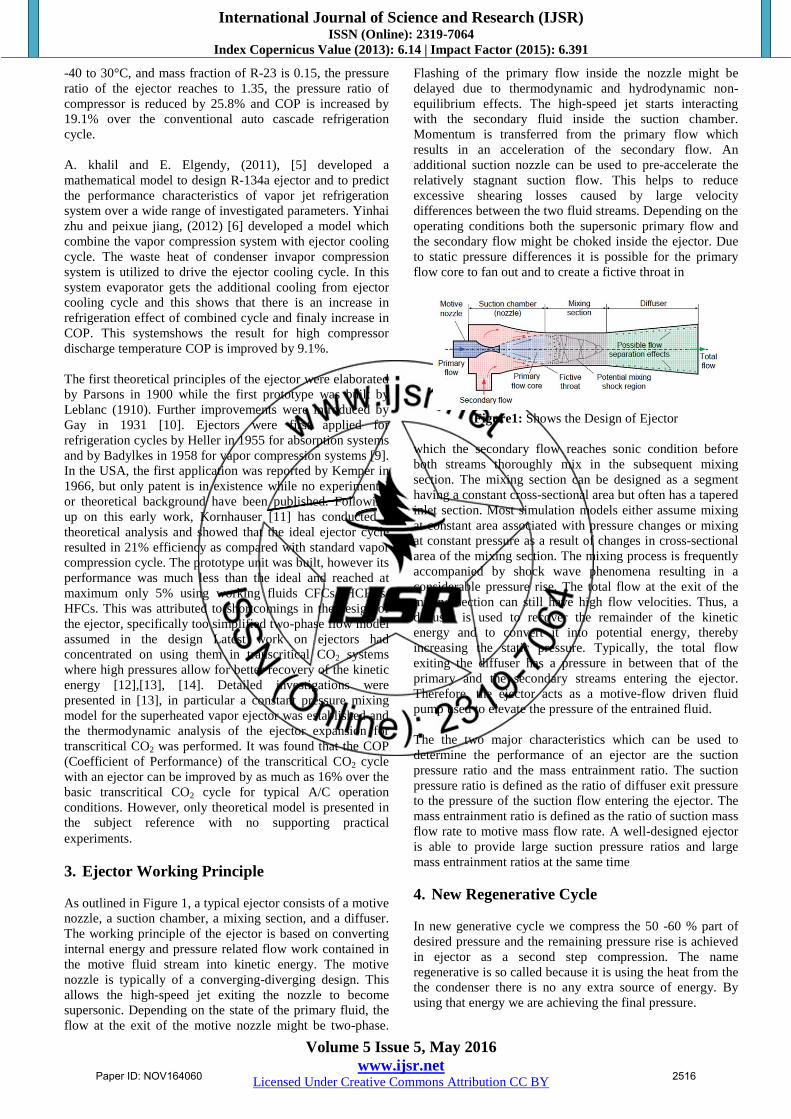
3. Ejector Working Principle
As outlined in Figure 1, a typical ejector consists of a motive
nozzle, a suction chamber, a mixing section, and a diffuser.
The working principle of the ejector is based on converting
internal energy and pressure related flow work contained in
the motive fluid stream into kinetic energy. The motive
nozzle is typically of a converging-diverging design. This
allows the high-speed jet exiting the nozzle to become
supersonic. Depending on the state of the primary fluid, the
flow at the exit of the motive nozzle might be two-phase.
Flashing of the primary flow inside the nozzle might be
delayed due to thermodynamic and hydrodynamic non-
equilibrium effects. The high-speed jet starts interacting
with the secondary fluid inside the suction chamber.
Momentum is transferred from the primary flow which
results in an acceleration of the secondary flow. An
additional suction nozzle can be used to pre-accelerate the
relatively stagnant suction flow. This helps to reduce
excessive shearing losses caused by large velocity
differences between the two fluid streams. Depending on the
operating conditions both the supersonic primary flow and
the secondary flow might be choked inside the ejector. Due
to static pressure differences it is possible for the primary
flow core to fan out and to create a fictive throat in
Figure1: Shows the Design of Ejector
which the secondary flow reaches sonic condition before
both streams thoroughly mix in the subsequent mixing
section. The mixing section can be designed as a segment
having a constant cross-sectional area but often has a tapered
inlet section. Most simulation models either assume mixing
at constant area associated with pressure changes or mixing
at constant pressure as a result of changes in cross-sectional
area of the mixing section. The mixing process is frequently
accompanied by shock wave phenomena resulting in a
considerable pressure rise. The total flow at the exit of the
mixing section can still have high flow velocities. Thus, a
diffuser is used to recover the remainder of the kinetic
energy and to convert it into potential energy, thereby
increasing the static pressure. Typically, the total flow
exiting the diffuser has a pressure in between that of the
primary and the secondary streams entering the ejector.
Therefore, the ejector acts as a motive-flow driven fluid
pump used to elevate the pressure of the entrained fluid.
The the two major characteristics which can be used to
determine the performance of an ejector are the suction
pressure ratio and the mass entrainment ratio. The suction
pressure ratio is defined as the ratio of diffuser exit pressure
to the pressure of the suction flow entering the ejector. The
mass entrainment ratio is defined as the ratio of suction mass
flow rate to motive mass flow rate. A well-designed ejector
is able to provide large suction pressure ratios and large
mass entrainment ratios at the same time
4. New Regenerative Cycle
In new generative cycle we compress the 50 -60 % part of
desired pressure and the remaining pressure rise is achieved
in ejector as a second step compression. The name
regenerative is so called because it is using the heat from the
the condenser there is no any extra source of energy. By
using that energy we are achieving the final pressure.
Paper ID: NOV164060 2516
International Journal of Science and Research (IJSR) ISSN (Online): 2319-7064
Index Copernicus Value (2013): 6.14 | Impact Factor (2015): 6.391
Volume 5 Issue 5, May 2016
www.ijsr.net Licensed Under Creative Commons Attribution CC BY
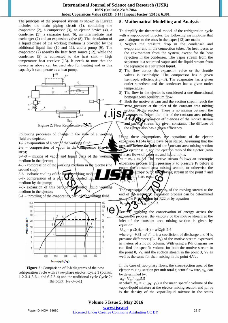
The principle of the proposed system as shown in Figure2
includes the main piping circuit (1), containing the
evaporator (2), a compressor (3), an ejector device (4), a
condenser (5), a separator tank (6), an intermediate heat
exchanger (7) and an expansion valve (8). The circulation of
a liquid phase of the working medium is provided by the
additional liquid line (10 and 11), and a pump (9). The
evaporator (2) absorbs the heat from source (12), while the
condenser (5) is connected to the heat sink – high
temperature heat receiver (13). It needs to note that the
device as above can be used also for heating and in this
capacity it can operate as a heat pump.
Figure 2: New Regenerative Cycle
Following processes of change in the state of a working
fluid are depicted:
1-2 - evaporation of a part of the working fluid;
2-3 – compression of vapor in the compressor (the first
step);
3-4-8 – mixing of vapor and liquid parts of the working
medium in the ejector;
4-5 - compression of the working medium in the ejector (the
second step);
5-6 - isobaric cooling of the liquid working medium;
6-7- compression of a part of the cooled liquid working
medium by the pump;
7-8- expansion of this part of the cooled liquid working
medium in the ejector;
6-1 – throttling of the evaporating part of the working fluid.
Figure 3: Comparison of P-h diagrams of the new
refrigeration cycle with a two-phase ejector, Cycle 1 (points:
1-2-3-4-5-6-1 and 6-7-8-4) and the traditional cycle Cycle 2:
(the point: 1-2-3'-6-1)
5. Mathematical Modelling and Analysis
To simplify the theoretical model of the refrigeration cycle
with a vapor-liquid injector, the following assumptions that
are analogous to the ones in the paper [12] are made:
1) Neglect the pressure drop in the condenser and
evaporator and in the connection tubes. No heat losses to
the environment from the system, except for the heat
rejection in the condenser. The vapor stream from the
separator is a saturated vapor and the liquid stream from
the separator is a saturated liquid.
2) The flow across the expansion valve or the throttle
valves is isenthalpic. The compressor has a given
isentropic efficiency(ɳc=.8). The evaporator has a given
outlet superheat and the condenser has a given outlet
temperature.
3) The flow in the ejector is considered a one-dimensional
homogeneous equilibrium flow.
4) Both the motive stream and the suction stream reach the
same pressure at the inlet of the constant area mixing
section of the ejector. There is no mixing between the
two streams before the inlet of the constant area mixing
section. The expansion efficiencies of the motive stream
and suction stream are given constants. The diffuser of
the ejector also has a given efficiency.
Using these assumptions, the equations of the ejector
expansion R134a cycle have been stated. Assuming that the
pressure before the inlet of the constant area mixing section
of the ejector is Pb and the ejection ratio of the ejector (ratio
of mass flows of vapor mv and liquid mf) is,
w = mv / mf 5.1 The motive stream follows an isentropic
expansion process from pressure Pi to pressure Pb before it
enters the constant area mixing section, or otherwise the
value of entropy Si for the moving stream in the point 7 and
in the point 8 are equal:
S7= S8 5.2
The corresponding enthalpy h8 of the moving stream at the
end of the isentropic expansion process can be determined
using the P-h diagram for R22 or by equation
h7 – h8 = (P7 – P8 ) / ρ 5.3
Further, applying the conservation of energy across the
expansion process, the velocity of the motive stream at the
inlet of the constant area mixing section is given by
equation:
Umb = μ√2(H8 – H7) = μ√2gH 5.4
where g= 9.81 m/ s2, μ is a coefficient of discharge and H is
pressure difference (P7– P8) of the motive stream expressed
in meters of a liquid column. With using a P-h diagram we
can find the specific volume for both the motive stream in
the point 8, V8, and the suction stream in the point 3, V3, as
well as the same for their mixing in the point 4,V4 .
In the case of two-phase flows, the cross-section area of the
ejector mixing section per unit total ejector flow rate, am, can
be determined by:
am= Vm / umb 5.5
in which Vm = 2/ (ρ4+ ρ5) is the mean specific volume of the
vapor-liquid mixture at the ejector mixing section and ρ4, ρ5
is the density of the vapor-liquid mixture in the states
Paper ID: NOV164060 2517
International Journal of Science and Research (IJSR) ISSN (Online): 2319-7064
Index Copernicus Value (2013): 6.14 | Impact Factor (2015): 6.391
Volume 5 Issue 5, May 2016
www.ijsr.net Licensed Under Creative Commons Attribution CC BY
corresponding to points 4 and 5 on the P-h diagram of
figure3.
The method employed here for calculating the cross-section
area of the mixing channel is characteristic of similar
techniques of two-phase ejector calculation given by
Fisenko [4]. From the known values of the velocity of the
mixing stream and across mixing section area(cross-section
area of the cylindrical channel at the mixing chamber
outlet), it is possible to calculate the pressures of the
working fluid flow at the mixing chamber outlet, Pmix, and at
the ejector outlet after the diffuser, Pd.
In this event the following equations were applied:
Pb am + (1
(1+w) ) *umb + (
1
(1+w)) *usb = Pm am + umix 5.6
Pd = Pmix + ρ (umix2 – ud
2) / 2 5.7
The former being the momentum conservation equation,
whereas the latter is the energy conservation equation in the
form of Bernoulli equation. In these equations umb, usb –
velocities of the liquid and vapor flows (motive and suction)
at the mixing section inlet, umix, ud -mixture flow velocity at
the diffuser inlet and outlet.
It needs to emphasize that in our case, the mixture velocity
in the mixing chamber has to be somewhat higher than local
sonic speed of this two-phase flow because in this case the
efficiency of the vapor-liquid ejector increases [4]. In its
turn, according to the known data [1], the speed of sound
propagation α in a two-phase medium can be as low as only
20-50 m/s and for its estimate one can apply the equation:
α 2 = kP /ρmix or a
2 = P//ρf β(1- β) 5.8
where k is isentropic coefficient, P, ρmix is pressure and
density of the two-phase flow, ρf is density of the liquid
phase and β is the volumetric content of vapor in the
mixture.
5.1 Governing Equations
A. Compressor
The compressor is assumed to be non-isentropic. Process 1-
2s is an isentropic compression process, while process 1-2 is
the actual compression process. The actual enthalpy of state
2 is expressed by:
h3 = h2 + (h3s – h2)/ɳc 5.9
where hc is the isentropic efficiency of the compression
process.
The enthalpy and entropy of the refrigerant at state 1 are
determined by the temperature and pressure at the
compressor inlet as:
h2 , s2= f(T2,P2) 5.10
The refrigerant enthalpy at state 2s for the isentropic process
is:
h3s= f( s3s,p3) 5.11
Where s3s=s2
The quantity of energy needed for the compression of the
vapor flow mv by the compressor with the performance ɳc is
determined by the expression
ℓc = mv(h3 – h2) / ɳc 5.12
B. Condenser/Generator In the regenerative system shown in Fig. 2, low temperature
fluid, which generates vapor by absorbing heat from the
high temperature compressor discharge, becomes the
working fluid to drive the ejector. Note that the condensing
temperature in the basic refrigeration cycle is lower than the
evaporating temperature of the ejector cycle. Therefore, only
part of the sensible heat can be used to vaporizing the
refrigerant of the ejector cycle in the generator. The total
energy balance in the vapor generator is:
m3(h3 – h4) = m10( h10 – h9) 5.13
For the heat exchanger design, there is a minimum
temperature difference at the generator’s two sides:
T3 > T10 + ΔTg, T4 = T9 + ΔTg 5.14
The fluid state at the generator exit is:
T4, s4= f(P4, h4) 5.15
T10, h10 s10= f(P3) 5.16
Qg= m(h3 – h4) 5.17
C. Pump:
In the regenerative system the pump is also used to raise the
pressure of mixing fluid. The total mass balance at the pump
is: m4 + m5 = m10 + m11 5.18
h7, s7 =f( T7,P7) 5.19
The quantity of energy ℓp, consumed by a pump in
compressing a working fluid is calculated with the formula
ℓp= mf ∆P7-6/( ρmix*ɳ) = mf(h7 – h6 ) /( ρmix*ɳ) 5.20
where ɳ is efficiency (coefficient of efficiency) of the pump.
D. Evaporator:
The function of the evaporator in the basic refrigeration
system differs from that in the hybrid system. For the
evaporator , assume that the refrigerant at the exit (state 1) is
super heated . The governing equations for the evaporator
are then
P1=fsat(Tevp.) 5.21 T2= Tevp. + ∆Te 5.22
h2,s2= f(T2, P2) 5.23
Refrigerating capacity of the system Qo
Qo = mv(h2 – h1) 5.24
E. Ejector:
The ejector works as a compression device where the high
pressure primary flow (state 13) entrains the low-pressure
secondary flow (state 7) into the ejector. Previous studies
have shown that the ejector performance is influenced by
both the ejector geometry and the operating conditions. The
ejector performance is usually evaluated based on the
combined mass flow rates of the two flows. The mass flow
rate of the primary flow of the ejector is determined by the
ejector’s structure and the thermodynamic properties of the
primary flow. Assuming isentropic flow, the mass flow rate
of the primary flow through the nozzle,m11, when choked
can be expressed by (Huang et al., 1999; Zhu et al., 2007).
m11= At[ ΨejγP11ρ11 ]1/2
(ρ/(1+γ))(γ+1)/2(γ-1)
5.25 where Ψej represents a coefficient related to the isentropic
efficiency of the compressible flow in the nozzle and P11 and
T11 are the pressure and temperature of the primary flow,
respectively, at the ejector inlet.
Paper ID: NOV164060 2518

International Journal of Science and Research (IJSR) ISSN (Online): 2319-7064
Index Copernicus Value (2013): 6.14 | Impact Factor (2015): 6.391
Volume 5 Issue 5, May 2016
www.ijsr.net Licensed Under Creative Commons Attribution CC BY
The characteristics of the secondary flow in the ejector are
more complex than those of the primary flow. In the critical
mode, the secondary flow is choked in the ejector
(hypothetical section 80) which determines the ejector
performance. Zhu and Li (2009) derived the following to
calculate the secondary flow mass flow rate:
m6=
2πρ7
Rm−R8√γP8
ρ8( Rm
3/6 – RmR
28/2 + R8
3/3) 5.26 where r80,
P80 and V80 are the density, pressure and velocity of the
primary flow, respectively, at a hypothetical section where
the secondary flow is choked and R80 is the radius of the
mixing layer in this hypothetical section
5.2 Other energy characteristics of the cycle are defined
as follows:
Thermal performance(Qh)
Qh = (mf + mv) (h5 – h6) = (mf + mv) cp(T5– T6) 5.27
The compression work ℓ done by the compressor and
the pump
ℓ = ℓc + ℓp 5.28
The coefficient of performance (COP) of the two phase
ejector cycle can be determined by:
COP = Qh /ℓ 5.29
For the basic one-step refrigeration cycle operating in
the same temperature range, the evaporator heat
capacity Qboand the condenser heat capacity Qbhare
given by:
Qbo = mv(hb2 – hb) 5.30
Qbh= mv (hb3 – hb6) 5.31
The compressor work of the same basic cycle operating
without using the ejector is found by:
ℓb = mv (hb3 – hb2) ɳ 5.32
where hbi are the enthalpies of the corresponding points in
the P-h diagram cycle of Fig. 5 where a comparison is
shown between one step compression conventional cycle
and the new cycle. Then, the performance of the basic
refrigerant cycle with the same temperature range is given
by:
COPb = Qbh / ℓb 5.33
In carrying out calculations it has been assumed that
coefficient of efficiency of the hydraulic pump and
compressor is equal to 0.8, and corresponding values
(magnitudes) of the evaporator capacity for both cycles
under consideration are identical.
Velocity of outflow of the motive fluid from the ejector
nozzle
Umb = μ√ 2(H7 – H8) 5.34
Cross-section area of the mixing nozzle
Am = 2/ (ρ4 + ρ5 ) umb 5.35
6. Results and Discussions
Performance of regenerative cycle with R134a:For the basic
cycle of vapor compression refrigeration system using
R134a as arefrigerant COP is=2.935, and for the
regenerative cycle using ejector as second step compression
COP is=3.589 which is higher than basic cycle of vapour
compression system. COP is increased by 22%. Where as
work of compression is also reduced.
Performance of regenerative cycle with R1234yf: For the
basic cycle of vapor compression refrigeration system using
R1234yf as a refrigerant COP=3.245, and for the
regenerative cycle using ejector as second step compression
COP=3.626, Which is higher than the basic cycle of vapor
compreesion system. COP is increased by 11.7 %, Where as
work of compression is also reduced.
Table 1: Qualities and quantity of R134a, R1234yf refrigerants
in characteristics points are indicated on the diagram.
Points P (bar) Ti (°C) Xi
1 4.2 -5 0.22
2 4.2 -5 1
3 11.9 35 1
4 11.9 30 0.1
5 24.2 55 ~0.01
6 24.2 40 0
7 30 41 0
8 11.9 30 ~0.02
3'' 24.2 85 1
Table 2: Effect of evaporator temperature on COP of R-
134a and R-1234yf
Te(0C) COP of R-134a COP of R-1234yf
-10 3.39 3.321
-8 3.42 3.479
-6 3.49 3.524
-4 3.541 3.262
-2 3.612 3.767
0 3.684 3.858
2 3.725 3.991
4 3.812 4.191
6 3.924 4.287
8 4.125 4.401
10 4.249 4.627
Figure 4: Effect of evaporator temperature on COP with
R134a
Paper ID: NOV164060 2519

International Journal of Science and Research (IJSR) ISSN (Online): 2319-7064
Index Copernicus Value (2013): 6.14 | Impact Factor (2015): 6.391
Volume 5 Issue 5, May 2016
www.ijsr.net Licensed Under Creative Commons Attribution CC BY
Figure 5: Effect of evaporator temperature on COP with
R1234y
7. Conclusions
In this paper performance analysis of a new regenerative
vapor compression cycle is done with R134a, R1234yf as a
refrigerant. Following things can be concluded,
1) COP of HFO-1234yf is 8.89% higher than R-134a at
higher evaporator temperature.
2) COP of the regenerative cycle is higher than the
conventional vapour compression cycle i.e. COP of R-
134a is increased by 22% and COP of R-1234yf is
increased by 11.7%.
References
[1] Mark J. Bergander, “New Regenerative Cycle for
Vapor Compression Refrigeration” DE-FG36-
04GO14327
[2] L. Kairouani, M. Elakhdar, E. Nehdi and N. Bouaziz,”
Use of ejectors in a multi-evaporator refrigeration
system for performance enhancement”, International
Journal of Refrigeration, Vol.32 (2009), pp.17-20.
[3] 3.Arbel, A., Sokolov, M., “Revisiting solar-powered
ejector air conditioner the greener the better”. Sol.
Energ. 77, pp.57-66.
[4] A Khalil, M.Fatouh and E. Elegendy, “ Ejector design
and theortical study of R134a ejector refrigeration
cycle’’ International journal of refrigeration vol.17,
2011, pp56-63
[5] Yinhai Zhu and Peixue Jiang, “Hybrid vapor
compression refrigeration system with an integrated
ejector cooling cycle” International journal of
refrigeration, vol.35, 2012, pp.68-78
[6] Jianlin Yu, Hua Zhao and Yanzhong Li,” Application
of an ejector in auto cascade refrigeration cycle for
the performance improvement”, International journal
of refrigeration, vol.31, 2008, pp.279-286.
[7] Downar-Zapolski P., et al., The Non-Equilibrium
Relaxation Model for One-Dimensional Flashing
Liquid Flow, Int. J. Multiphase Flow, Vol. 22, No.3,
1996, pp.473-483
[8] Smith I.K., Stosic, N.R., The Expressor: An Efficiency
Boost to Vapour Compression Systems by Power
Recovery from the Throttling Process, AES, vol. 34,
Heat Pump and Refrigeration Systems Design,
Analysis and Applications, ASME 1995, pp.173-181
[9] Bohdal, T., et al., Urzadzenia Chlodnicze Sprezarkowe
Parowe, (book in Polish), WNT, Warsaw, 2003, 531 p.
[10] Gay, N.H., 1931, “Refrigerating System”, US Patent
No. 1,836,318
[11] Kornhauser, A.A., “The use of and Ejector as a
Refrigerant Expander”, Proc. of 1990 USNCR/IIR-
Purdue Refrigeration Conference West Lafayette, IN.
p.10-19.
[12] Hays L., Brasz J.J., A Transcritical CO2 Turbine-
Compressor, International Refrigeration and Air
Conditioning Conference at Purdue, July 12-15, 2004,
Paper No. C137
[13] Li D., Groll, E.A., “Transcritical CO2 Refrigeration
Cycles with Ejector-Expansion Device”, International
Refrigeration and Air Conditioning Conference at
Purdue, July 12-15, 2004, Paper No. R153
[14] Elbel, S.W., and Hrnjak, P.S.,“Effect of Internal Heat
Exchanger on Performance of Transcritical CO2
Systems with Ejector”, International Refrigeration and
Air Conditioning Conference at Purdue, July 12-15,
2004, Paper No. R166
[15] Althouse, A.D., Turnquist, C.H., Bracciano, A.F.,
“Modern Refrigeration and Air Conditioning”, The
Goodheart-Willcox Company, 2004, pp 11-12.
[16] Huang, B.J., Chang, J.M., Wang, C.P., Petrenko,
V.A.,.” A 1-D analysis of ejector performance”. Int. J.
Refrigeration 22, te354e364.
[17] Huang, B.J., Hu, S.S., Lee, S.H.,. “Development of an
ejector cooling system with thermal pumping effect".
Int. J. Refrigeration 29 (3), 476e484
[18] Zhu, Y.H., Li, Y.Z.,. “Novel ejector model for
performance evaluation on both dry and wet vapors
ejectors”. Int. J. Refrigeration 32, 21e31.
[19] S.A. Klein And F. Alvarado, Engineering Equation
Solver, F Chart Software, Middleton, Wi,
Version9.224,2012.
[20] A Paper Entitled “Thermodynamic Analysis Of Actual
Vapour Compression System With Hfo-1234yf And
Hfo-1234ze As An Alternative Replacement Of Hfc-
134a”, International Journal Of Sciences And
Research (Ijsr), Volume 5 Issue 4, April
2016.Pg(1684-1689).
Paper ID: NOV164060 2520