
Theoretic foundation_ the electret
16
06-06-13 Theoretic foundation: the electret effect - Printable Version 1/16 open-source-energy.org/forum/printthread.php?tid=1168 Theoretic foundation: the electret effect - Printable Version +- open-source-energy.org (http://open-source-energy.org/forum) +-- Forum: OPEN-SOURCE-ENERGY.ORG (/forumdisplay.php?fid=3) +--- Forum: RWGRESEARCH.COM (/forumdisplay.php?fid=4) +--- Thread: Theoretic foundation: the electret effect (/showthread.php?tid=1168) Theoretic foundation: the electret effect - lamare - 05-10-2013 03:35 AM Hi all, Agnar Kill said this to me on facebook: Quote:hi Arend, read a comment you made at energetics forum, you said.. ''you could come up with a system that feeds "spikes" to the cap in order to maintain that non-permanent electret effect for a prolonged period of time, while only taking a minimal amount of energy to maintain the electret.'' this in a thread about Noelectrolysis water split.. Some time ago, I posted some ideas on the energetic forum about the electret effect, an observed effect that may very well be the key to understanding Meyer's technology. There's a section on "the electret effect" in my article at PES, where there are links to the EF discussion, and at the bottom there is a link to a bedini video and some other material on what happens on the plates of the batteries: http://peswiki.com/index.php/Article:Free_Electric_Energy_in_Theory_and_Practice#The_Electret_Effect Bedini says something changes on his battery plates, and I think what happens is that a dielectric layer is grown, much like what happens in an electrolytic capacitor, especially the ones they made in the old days. See: http://www.tuks.nl/Mirror/SparkBangBuzz/varelec-el.htm and http://www.tuks.nl/Mirror/SparkBangBuzz/borax-el.htm I'm pretty sure this is the key to understanding Meyer's technology. Will re-post some comments I made on the NPA_Dissidents Yahoo group on the matter. NPA group extract 1: Prof. Claus Turtur wrote an interesting piece, wherein he shows that the propagating electric (and magnetic) fields loose energy (to the vacuum), while apparently the particles (electrons, atom nuclieï, etc) that emit these fields draw energy from somewhere, since they don't loose mass. He came up with the idea that there is a circulation of energy between the vacuum and these particles and therefore you can in principle tap the energy emitted by particles in the shape of electro-magnetic fields: http://www.wbabin.net/physics/turtur1e.pdf When you accept the propagating EM fields to transport energy and you accept particles to somehow draw energy from the vacuum, which they emit in the shape of "static" electro-magnetic fields, then you have a foundation for building devices which draw their energy from the vacuum. I believe Stan Meyer did this by creating a thin, semi-permanent polarized dielectric layer on his fuell cell tubes, which would be akin to an electret, just as happens in a normal electrolytic capacitor. Because these layers are very thin, it apparently is possible to induce a very strong electric field in a thin area inside the water around the dielectric, such that the field strength exceeds the dielectric breakdown fieldstrength of water, which then apparently splits into hydrogen and oxygen. So, then you have a polarized dielectric which is, according to Turtur, capable of pulling in energy from the vacuum and convert that to electric field energy. And then this energy is converted into a usable fuel by having it split water into hydrogen and oxygen. At least, that's my theory in a nutshell. Extract 2: > > >I believe Stan Meyer did this by creating a thin, semi-permanent polarized dielectric layer on his fuell cell tubes, which would be akin to an electret, just as happens in a normal electrolytic capacitor. Because these layers are very thin, it apparently is possible to induce a very strong electric field in a thin area inside the water around the dielectric, such that the field strength exceeds the dielectric breakdown fieldstrength of water, which then apparently splits into hydrogen and oxygen. > > > Stan Meyer . Was the energy output greater than the energy input without being clouded in smoke and mirrors . The input is water and
Transcript of Theoretic foundation_ the electret

06-06-13 Theoretic foundation: the electret effect - Printable Version
1/16open-source-energy.org/forum/printthread.php?tid=1168
Theoretic foundation: the electret effect - Printable Version
+- open-source-energy.org (http://open-source-energy.org/forum)+-- Forum: OPEN-SOURCE-ENERGY.ORG (/forumdisplay.php?fid=3)+--- Forum: RWGRESEARCH.COM (/forumdisplay.php?fid=4)+--- Thread: Theoretic foundation: the electret effect (/showthread.php?tid=1168)
Theoretic foundation: the electret effect - lamare - 05-10-2013 03:35 AM
Hi all,
Agnar Kill said this to me on facebook:
Quote:hi Arend, read a comment you made at energetics forum, you said.. ''you could come up with a system that feeds"spikes" to the cap in order to maintain that non-permanent electret effect for a prolonged period of time, while only taking aminimal amount of energy to maintain the electret.'' this in a thread about Noelectrolysis water split..
Some time ago, I posted some ideas on the energetic forum about the electret effect, an observed effect that may very well be the key tounderstanding Meyer's technology.
There's a section on "the electret effect" in my article at PES, where there are links to the EF discussion, and at the bottom there is a linkto a bedini video and some other material on what happens on the plates of the batteries:
http://peswiki.com/index.php/Article:Free_Electric_Energy_in_Theory_and_Practice#The_Electret_Effect
Bedini says something changes on his battery plates, and I think what happens is that a dielectric layer is grown, much like what happensin an electrolytic capacitor, especially the ones they made in the old days.
See: http://www.tuks.nl/Mirror/SparkBangBuzz/varelec-el.htm and http://www.tuks.nl/Mirror/SparkBangBuzz/borax-el.htm
I'm pretty sure this is the key to understanding Meyer's technology.
Will re-post some comments I made on the NPA_Dissidents Yahoo group on the matter.
NPA group extract 1:
Prof. Claus Turtur wrote an interesting piece, wherein he shows that the propagating electric (and magnetic) fields loose energy (to thevacuum), while apparently the particles (electrons, atom nuclieï, etc) that emit these fields draw energy from somewhere, since they don'tloose mass. He came up with the idea that there is a circulation of energy between the vacuum and these particles and therefore you canin principle tap the energy emitted by particles in the shape of electro-magnetic fields:
http://www.wbabin.net/physics/turtur1e.pdf
When you accept the propagating EM fields to transport energy and you accept particles to somehow draw energy from the vacuum,which they emit in the shape of "static" electro-magnetic fields, then you have a foundation for building devices which draw their energyfrom the vacuum.
I believe Stan Meyer did this by creating a thin, semi-permanent polarized dielectric layer on his fuell cell tubes, which would be akin to anelectret, just as happens in a normal electrolytic capacitor. Because these layers are very thin, it apparently is possible to induce a verystrong electric field in a thin area inside the water around the dielectric, such that the field strength exceeds the dielectric breakdownfieldstrength of water, which then apparently splits into hydrogen and oxygen.
So, then you have a polarized dielectric which is, according to Turtur, capable of pulling in energy from the vacuum and convert that toelectric field energy. And then this energy is converted into a usable fuel by having it split water into hydrogen and oxygen.
At least, that's my theory in a nutshell.
Extract 2:
>> >I believe Stan Meyer did this by creating a thin, semi-permanent polarized dielectric layer on his fuell cell tubes, which would be akin toan electret, just as happens in a normal electrolytic capacitor. Because these layers are very thin, it apparently is possible to induce avery strong electric field in a thin area inside the water around the dielectric, such that the field strength exceeds the dielectric breakdownfieldstrength of water, which then apparently splits into hydrogen and oxygen.>>> Stan Meyer . Was the energy output greater than the energy input without being clouded in smoke and mirrors . The input is water and

06-06-13 Theoretic foundation: the electret effect - Printable Version
2/16open-source-energy.org/forum/printthread.php?tid=1168
> Stan Meyer . Was the energy output greater than the energy input without being clouded in smoke and mirrors . The input is water andthe result of hydrogen / oxygen combustion is water . The writing in on the wall . The conservation of energy is a founding principle ofphysics that has stood the test of time . Mr Meyer seems to be a nice guy . I do not mean to be unkind however after watching his video Imust conclude he is psychologically delusional believing god has given him a mission . It is sad to watch considering he has a bright mindand could have made fine contributions if life had dealt different cards.>>> http://www.youtube.com/watch?v=Vd7QL1-NnlU>
Yes, of course the conservation of energy is a founding principle of physics that cannot be overcome!
However, when you are capable of using an energy source that is already available, like for example light waves coming from the sun, thenthere is no breaking of energy conservation, while you still are able to get more energy out of the system than the energy you need to putin in order to get it. It is the exact same principle as using a solar-cell.
A better example is a Geothermal heat-pump.
https://en.wikipedia.org/wiki/Geothermal_heat_pump
"Like a refrigerator or air conditioner, these systems use a heat pump to force the transfer of heat from the ground. [...] The geothermalpump systems reach fairly high Coefficient of performance (CoP), 3-6, on the coldest of winter nights, compared to 1.75-2.5 for air-sourceheat pumps on cool days. Ground source heat pumps (GSHPs) are among the most energy efficient technologies for providing HVAC andwater heating."
You need to spend a certain amount of energy to pump water down into the ground, etc., which is heated by the ground, an energysource that is available for free. The trick is that you spend less energy pumping the water down than the energy you obtain in the shapeof heat which is extracted from the Earth, and thus you can obtain a COP > 1, meaning more energy out than in.
All right. Now the thesis of Prof. Turtur is that the "static" electric and magnetic field which are emitted by charge carrierscontains/transports energy, energy which is somehow obtained by these charged particles from the environment whatever you may wantto call it (zero-point energy, quantum fluctuations, Dirac Sea, whatever). In other words: particles extract energy from somewhere andmake it available as a/o "static" electric field energy *without* breaking the law of energy conservation.
The question then becomes: how can we make use of this energy, just like we can use the wind to power a windmill or the sun's light topower a solar cell?
I believe one answer to that question is to use a polarized dielectric which creates a strong enough electric field that can break water intohydrogen and oxygen, whereby the dielectric transfers energy from the vacuum into the electric field it emits.
In other words: the idea is to use energy that is naturally extracted for free from the environment / vacuum / aether by a polarizeddielectric in order to split water into hydrogen and oxygen, whereby you essentially convert some form of available energy into another,the latter being a useable fuel in the shape of hydrogen / ogygen gas.
For more details, see:
http://peswiki.com/index.php/Article:Free_Electric_Energy_in_Theory_and_Practice#The_Electret_Effecthttp://www.energeticforum.com/water-fuel/5590-basic-electrolysis-13.html#post102858
"Of course, this may not be the only phenomenon observed, but one thing is certain: Bedini's batteries do "cold boil" *after* the power hasbeen shut of. In other words: there is at least one known way to split water into hydrogen and oxygen that can last long after any powerhas been fed into the system. The only way I see to explain that is that a (non permanent) electret layer has been formed on the platesinside the batteries, which is basically a polarised insulating layer."
Extract 3:
Let's first get one thing straight we agree on:
One cannot break the fundamental law of conservation of energy.
But, you can have "free energy" in the sense that you can extract energy out of some energy source you don't have to pay for in terms ofdollars. There are numerous examples of this, like solar power, wind power, water power (Hoover's dam), Geothermal power, etc., etc.These are all accepted forms of free energy in my view which are commercially available and thus beyond the prototype stage already. Idon't think there is any discussion about that either, so to me it is clear that you *can* have free energy without breaking theconservation of energy. It's just a matter of finding an energy source that is available for free.Now of course the proof of the pudding is in the eating, but you can't make a good pudding without having a good recipe. So, if we wantto build another kind of free energy devices, we will first have to identify a usable energy source and then figure out a way how to utilizeit.The first step towards that goal is the identification of a possible energy source and since it is well accepted that the static electric fieldstores/transports energy, it clearly is a candidate for such an energy source:
http://en.wikipedia.org/wiki/Electric_field#Energy_in_the_electric_field
"The electrostatic field stores energy. The energy density u (energy per unit volume) is given by ..."
Now since charged particles emit an electro"static" field, which propagates at the speed of light, it is clear that charged particles emitenergy which is transported by the electric field into space.
Energy that must come from somewhere, because otherwise there would be a violation of conservation of energy. It is therefore obviousthat charged particles are somehow extracting energy from their environment which they convert into "static" electric field energy. Prof.Turtur's thesis explains how this works, but the bottomline is that charged particles emit energy, energy that can (potentially) be utilizedfor free.
It's really just like wind or water power, just a matter of *conversion* of energy from one form into another. With wind or water power,one usually converts mechanical energy into electric energy using a generator. In this case, we need to convert electro-"static" energyinto some usable form. So, all we need to do is find a way *how* to do this.

06-06-13 Theoretic foundation: the electret effect - Printable Version
3/16open-source-energy.org/forum/printthread.php?tid=1168
From this patent, it is clear that one can split water into hydrogen and oxygen using a sufficiently strong electric field:
http://www.tuks.nl/pdf/Patents/Eccles%20-%20Fracture%20Cell%20Apparatus%20-%20GB%202.324.307A.pdf
Now in this patent, they use like 25 kV over like 5 mm (or 5 MV/m) in order to induce a field with sufficient strength into the water.However, if you use an electrolytic capacitor whereby the ions inside your fluid form one of the capacitor plates, you have a very smallplate distance:
http://en.wikipedia.org/wiki/Capacitor
"Electrolytic capacitors use an aluminum or tantalum plate with an oxide dielectric layer. The second electrode is a liquid electrolyte,
connected to the circuit by another foil plate."
http://www.ami.ac.uk/courses/topics/0136_ec/"A number of metals, such as tantalum, aluminium, niobium, zirconium and zinc, can be coated with an oxide film by electrochemical means.
By placing the metal in an appropriate solution and passing a current though the circuit, a thin layer of oxide forms on the anode. [...]What we have done is to produce an oxide that will ‘withstand’ the applied forming voltage, and will not grow and grow as rust does. Thisoxide film can be extremely thin1 (typically less than 1µm) as well as having a acceptably high dielectric constant. "
In other words, one can achieve the required field strength of about 5 MV/m inside a typical electrolytic capacitor by applying 5 MV * 1 µm= 5 V of potential across the terminals. And actually, unintended electrolysis is a well known problem with electrolytic capacitors, eventoday:
http://en.wikipedia.org/wiki/Capacitor_plague
"The situation of unimpeded formation of hydroxide (hydration) and associated *hydrogen* *gas* *production* occurred during "capacitorplague" or "bad capacitors" incidents involving the failure of large numbers of aluminum electrolytic capacitors. [...] Because it has beencustomary in electrolytic capacitors to *bind* the *excess* *hydrogen* with the help of reducing or depolarizing compounds to reducethe resulting pressure, the researchers then searched for compounds of this type."
So, therefore, I believe we have all the ingredients for our free energy pudding recipe right in front of our eyes.
To sum this up, what I am saying is:
1. I agree that the law of conservation of energy is a fundamental law which cannot be broken.
2. I disagree that you cannot make free energy devices, because one can utilize an energy source that is freely available, such as wind,water or sunlight.
3. Theoretically, any available energy source can be utilized.
4. It is well accepted that the electric field stores/contains energy.
5. It is well accepted that charge carriers emit electric fields and thus emit energy, which can thus in principle be utilized, all withoutviolation of conservation of energy.
6. There is a patent which claims that a strong electric field can be utilized to split water into hydrogen and oxygen.
7. It is well known that electrolytic capacitors release hydrogen gas, which normally is unintended and creates a problem which takes quitea lot of effort to overcome.
Now you can argue that steps 5 - 7 is not what causes electrolytic capacitors to release hydrogen gas and that some other mechanism isresponsible for that. I don't think so, but one cannot entirely rule out the possibility.
Other than that, I think this is a nice recipe for some kick-***** pudding, and I believe the prototype you were asking for has been builtby Stanley Meyer and can thus be replicated using the principles stated just above. However, I do agree that the prove of the pudding isin the eating, so we will not know for sure before someone actually succeeds in building something like this.
I do intend to experiment with this stuff at some point in the future, wherein I intend to use this recipe for making DIY electrolyticcapacitors:
http://www.tuks.nl/Mirror/SparkBangBuzz/varelec-el.htmhttp://www.tuks.nl/Mirror/SparkBangBuzz/borax-el.htm
However, at this moment I do not have the time to do so, because I amworking on another project:
http://www.energeticforum.com/renewable-energy/9727-who-performs-first-longitudinal-moon-bounce-history-6.html#post230353
RE: Theoretic foundation: the electric effect - Dog-One - 05-10-2013 07:43 AM
Welcome aboard lamare and thank you for the relevant and thoughtful post.
Some experimenters here have touched on the water capacitor concept, but to date I know of no one that has successfully producedlarge quantities of HHO from such a device without exceeding Faraday's constant. I would be happy to be wrong; if so, please do correctme.
Looking at electrolysis from a rather naive view, it appears two things are important for quantity production of HHO: Current flow andsurface area.
As I've stated on this forum before I feel what we lack is true understanding of what we call electrolysis. At a subatomic particle level, I'mnot confident that we know the fundamental workings of even simple brute force electrolysis. And until we do, figuring out a way toimprove its COP will remain allusive.

06-06-13 Theoretic foundation: the electret effect - Printable Version
4/16open-source-energy.org/forum/printthread.php?tid=1168
I also think what plagues our development is not having a good working prototype to evaluate. We have lots of patents, ideas and testfixtures, but nothing concrete that clearly demonstrates a process in action. This leads to skepticism and rightfully so. There is a lot ofhoaxed material out in the wild. I know first hand having spent many hours and resources replicating a couple of them, only to find out theresults fall orders of magnitude short of what was claimed. This is an unfortunate artifact of our Internet free-for-all and requires anunanticipated level of discernment many researchers lack, me included.
We look forward to you bringing something to the table that will boost our level of understanding and confidence. Please do feel free tostart a thread in our projects section when you are ready to begin building.
RE: Theoretic foundation: the electric effect - lamare - 05-10-2013 08:52 AM
Quote:Some experimenters here have touched on the water capacitor concept, but to date I know of no one that hassuccessfully produced large quantities of HHO from such a device without exceeding Faraday's constant. I would be happy tobe wrong; if so, please do correct me.
Looking at electrolysis from a rather naive view, it appears two things are important for quantity production of HHO: Currentflow and surface area.
As I've stated on this forum before I feel what we lack is true understanding of what we call electrolysis. At a subatomicparticle level, I'm not confident that we know the fundamental workings of even simple brute force electrolysis. And until wedo, figuring out a way to improve its COP will remain allusive.
John Bedini reported that his batteries were "coild boiling" (i.e. produce H2 / O2 gas) for up to half an hour *after* he shut the poweroff, an unwanted effect in his case, but IMHO an example of producing HHO(*) without feeding current to the cell.
What is important to realize is that you do not necessarily need the current to flow from the outside into the fluid, you *can* have acurrent flowing within the fluid itself, without having it also flowing trough your terminals.
The way to accomplish that is to have a strong enough electric field present within the fluid, such that it rips of some of the electrons ofsome of the atoms, thus freeing them. The required field strength to do that is known as "dielectric breakdown", since (pure) water is alsoa dielectric.
Posted some on that on the EF a while ago:http://www.energeticforum.com/107700-post25.html
Quote:For water, this happens when field strengths in the order of 30 MV/m, or 30 kV/mm, or 3 kV/ 0.1mm are reached.
http://www.energeticforum.com/107754-post32.html
Quote:Geven the electric strength of pure water, 30 kV/mm, it is clear the required field strength is achievable with capacitorplates placed at a distance of 1 mm. When you are talking about the thin dielectric films used in electrolytic capacitors whichare in the order of a few micrometer, you already come within the required range with something in the order of 60 V.
Now you need a pretty strong field strength in order to do that, which normally means a high voltage across your capacitor plates, *but*because the capacitor "plates" are very close to one another in an electyrolytic capacitor construction (whereby one of the plates is anactual plate and the other is formed by ions in the electrolyte) you have a "plate" distance in the order of 1 um, and then the requiredvoltage across the terminals is in the order of tens of Volts.
In that sense, it is interesting to consider why you get "the glow" with an aluminum - borax based rectifier:
http://www.tuks.nl/Mirror/SparkBangBuzz/borax-el.htm
Quote:The glow is produced on the reverse bias cycle of each rectifier.
Could that be caused by "tiny sparks" within the fluid, within a very tiny region on top of the surface of your plates, whereby you get this"internal current" whereby electrons jump from one molecule to the next, thus not only producing "the glow" but also producing HHO gas???
Note that the glow is produced in the reverse bias cycle of the (aluminim/liquid) rectifier, which means that it is not conducting during thetime the glow is produced.

06-06-13 Theoretic foundation: the electret effect - Printable Version
5/16open-source-energy.org/forum/printthread.php?tid=1168
(05-10-2013 07:43 AM)Dog-One Wrote: I also think what plagues our development is not having a good working prototype toevaluate. We have lots of patents, ideas and test fixtures, but nothing concrete that clearly demonstrates a process in action.This leads to skepticism and rightfully so. There is a lot of hoaxed material out in the wild. I know first hand having spent manyhours and resources replicating a couple of them, only to find out the results fall orders of magnitude short of what wasclaimed. This is an unfortunate artifact of our Internet free-for-all and requires an unanticipated level of discernment manyresearchers lack, me included.
We look forward to you bringing something to the table that will boost our level of understanding and confidence. Please dofeel free to start a thread in our projects section when you are ready to begin building.
I know there is a lot of B.S. out there. To be honest, I have nothing to back up this theory other than my study of lots of material and theconfidence that what Bedini reported is accurate and the reporting of others observing what we called "the electret effect" withelectrolytic capacitors charged with Bedini type chargers, and my background of holding a Masters degree in Electrical Engineering.
I posted some links here on where I got the background ideas:http://www.energeticforum.com/76020-post17.html
So, to me things add up and I think the theoretic foundation is solid, but you may differ in opinion. All I can do at this moment is share mythoughts, I don't have the time to experiment with this now, because I am working on another project, as I already said:
http://www.energeticforum.com/renewable-energy/9727-who-performs-first-longitudinal-moon-bounce-history-6.html#post230353
In other words: I post this stuff in the hope it may be useful and that it may help others with their experiments. It may turn out to be avital key, but it may also turn out that Meyer used some other mechanism.
However, Turtur's thesis at least offers a fundamental understanding of where the energy is coming from. There may be other mechanismto utilize that, but I am pretty sure that given the observations reported by others in various situations that a polarized dielectric within anelectrolytic capacitor or lead-acid battery explains the observed phenomena pretty well.
And at the bright side: at least I don't claim any results of any kind you can be dissapointed by when replicating.
(*) Note that I am using the term HHO as an abbreviation for "H2 / O2 gas" aka "Oxyhydrogen". See:http://en.wikipedia.org/wiki/Oxyhydrogen.
RE: Theoretic foundation: the electric effect - lamare - 05-10-2013 03:16 PM
Posted this in the "Stanley Meyer Water Car Injector Drawings For The Water Powered Buggy!" thread. It says it's posted, but I can't findit back, so I post it here as well:
Quote:Securesupplies,
I'm sure that would work just fine. A low dielectric constant is important because you don't want the capacitance of the largepart of the injector effeceting the tapered area capacitance. Macor has a dielectric constant of about 6 unitl the temp goesbeyond 150 C. As we all know macor is what Meyer used but it is quite expensive.
IMHO, the dielectric layer is one of the most, if not THE most, important design element of the whole system. I posted a thread on how Ibelieve the system is capable of drawing energy from the environment (vacuum, zero-point, dirac-sea, aether, whatever you want to callit):
http://www.open-source-energy.org/forum/showthread.php?tid=1168
I believe, based on reported observations by a/o John Bedini that the secret of the whole system is to be found in the properties of thedielectric layer within the fuel cell (or injector, which appears to contain a tiny fuel cell).
It has been a head-ache for many years in solving the question of how to prevent electrolytic capacitors from generating HHO, anunwanted effect when building electrolytic capacitors.
An electrolytic capacitor, contrary to what many people think, is not just two capacitor plates with a dielectric in between. One of the"plates" is no more than a contact plate between the terminal and the electrolyte fluid. The other plate is an actual plate, on which a tinylayer of dielectric (often aluminum oxide) is grown by means of an electochemical process. The actual other "plate" of such a capacitor isthen formed by the ions in the electrolyte fluid, whereby the dielectric layer is in the order of 1 um thick. In the old days, radio amateursused aluminum plates and baking soda as an electrolyte.
Now what happens when you put aluminum plates in a baking soda bath and put a voltage across them, on the positive plate such a layerof dielectric grows automagically such that it becomes thick enough to withstand the applied voltage. If you want to make an electrolyticcapacitor that way, you need to apply like 10% extra voltage during the growing process, so the dielectric grows just a little bit thickerthan needed for the intended usage voltage.
The next thing that is very interesting is what happens when you apply high voltage spikes to an electrolytic capacitor. When you do thatfor a while, the capacitors start to show a significant increase of what is known as "dielectric relaxation" effect. When you charge an elcoto, say 10 V, and then shortly short circuit it, then after a few seconds or a minute or so, it will spontaneously recharge itself to about10% of the original voltage. That is the dielectric relaxation effect.
Electrolytic capacitors (as well as lead-acid batteries) which have been charged with high voltage spikes, Bedini's method, show a behaviorwhereby they spontaneously re-charge to much higher voltages.
I believe this occurs because the thin dielectric layer gets super-polarized by these *sudden* high voltage spikes.
Now if that is correct, and indeed you get a very strong electric field within your polarized dielectric, this field extends into the electrolytefluid. Now because the layer is very thin, this field can be very strong, and exceed the dielectric breakdown strength of water and thus

06-06-13 Theoretic foundation: the electret effect - Printable Version
6/16open-source-energy.org/forum/printthread.php?tid=1168
fluid. Now because the layer is very thin, this field can be very strong, and exceed the dielectric breakdown strength of water and thuscauses the water to spontaneously split into hydrogen/oxygen gas, which can be used as a fuel.
Interestingly, when experiments are being done with old-school rectifiers, basically the same construction, a glow is being observed overthe surface of the aluminum plates. I believe this same kind of glow has been reported with some more successfull fuel cell replications(Rahni or something?).....
So, if this indeed is the mechanism by which the system draws it's energy from the environment, the thickness of the layer is very, veryimportant, because that relates directly to the field strength that results within the dielectric when you apply an external voltage in orderto "charge" the capacitor and thus polarize the dielectric, which eventually gives you the power to produce your gas. (see thread postedabove).
In other words: the thickness and properties of the dielectric layer determine whether or not your system will function as desired. It is veryhard to produce very thin layers of dielectric with a constant thickness onto a rough material such as metal, unless you grow the layerelectrochemically.
With aluminum, we know exactly how to do that. The industry does it all the time when they make an electrolytic capacitor, and the DIY
version with baking soda also works, albeit that those are plagued with unintended HHO production.
So, it may be worthwhile to experiment with homemade aluminum and baking soda electrolytic capacitors in order to see whether or notthe effect I think is responsible for the working principle of the device indeed works as I say it does. If that turns out to be correct, youthen also have the information you need in order to make dielectric layers with desired properties on other metals, such as stainless steel.
Stainless steel does contain other metals that prevent it from rusting by growing a dielectric layer, which thickness then needs to becontrolled in order to get a layer that is just thick enough to withstand the voltages you apply to it in order to polarize the material, sothat it induces a strong electric field in your fluid which makes the water to split without having to apply an external current trough thefluid itself...
RE: Theoretic foundation: the electric effect - Dog-One - 05-10-2013 04:21 PM
Okay, lets try a slightly different angle here. Lets suppose we have two relatively closely spaced plates, one coated in a dielectric materialand the other bare. Now instead of using liquid as the electrolyte, we use water vapor. We still create the high voltage electric field assuggested. Could we pump water vapor through this electric field and and have it breakdown the same way? Which voltage plate needs tohave the dielectric coating? And what flow rate per plate surface area would we need to ensure all of the water vapor converted to HHO?Seems to me the electric field strength would be dependent upon the plate gap and dielectric strength, any idea what voltages we wouldbe talking here? Can we induce an electric field via a magnetic field instead?
I have heard it mentioned that "cracking" the water prior to ionization is essential. Such methods include forced cavitation of liquid water,whereby you pull off the "cracked" water, then ionize it. How does this play into the electric effect and what does cracking actually do tothe water than makes it easy to ionize?
Sorry, lots of questions that need answers before we can attempt a well designed build of such a device. That's what this forum is herefor, to get down to the bottom of it.
RE: Theoretic foundation: the electric effect - lamare - 05-11-2013 05:01 AM
(05-10-2013 04:21 PM)Dog-One Wrote: Okay, lets try a slightly different angle here. Lets suppose we have two relativelyclosely spaced plates, one coated in a dielectric material and the other bare. Now instead of using liquid as the electrolyte, weuse water vapor. We still create the high voltage electric field as suggested. Could we pump water vapor through this electricfield and and have it breakdown the same way? Which voltage plate needs to have the dielectric coating? And what flow rateper plate surface area would we need to ensure all of the water vapor converted to HHO? Seems to me the electric fieldstrength would be dependent upon the plate gap and dielectric strength, any idea what voltages we would be talking here?
Eccless did something along that direction, based on the work of Meyer. He refers to one of Meyers patents, although he did not use watervapor IIRC and he put the dielectric outside of the reactor chamber:http://www.tuks.nl/pdf/Patents/Eccles%20-%20Fracture%20Cell%20Apparatus%20-%20GB%202.324.307A.pdf
http://www.tuks.nl/pdf/Patents/Eccles%20-%20Fracture%20Cell%20Apparatus%20-%20OCR%20remake%20GB2324307A.pdf
Either way, when you want to use water vapor, then you don't really have a conducting electrolyte, so I suppose your capacitor will actmuch more like a normal capacitor with some dielectric layers in between. In practice, that means that you do not get an electrolyticcapacitor and thus both of your plates will be "real" capacitor plates.
Normally, when you charge a capacitor, the dielectric gets polarized and will oppose the electric field that is being induced by the capacitorplates (which also happens with an electrolytic cap, btw). I guess it is a good idea to coat the plates in order to isolate them, but thecoating will work against the field you induce for splitting the water, which means you need a higher voltage compared to the case withoutdielectric coating.
The required field strength lies in the order of 70 KV/mm, the dielectric breakdown strength of distilled water (http://en.wikipedia.org/wiki/Dielectric_strength ), which is quite considerable, but achievable. In such a case, it is the charge carriers onyour capacitor plates that are able to draw energy from the environment, so it is possible to achieve a COP>1. However, working with highvoltages is pretty challenging.
In that sense, it is interesting to know whether or not Meyer's injectors actually worked (as tiny fuel cells). I am confident that he did gethis car to run on water, but I am not aware of any information which confirms that he actually did so using his injectors, but the material Ihave read is quite limited compared what you guys got these days. I have a lot of reading up to do, but it would be nice if it could beconfirmed whether or not he actually ran his car on the injectors at some point, or that he "only" succeeded with running his car on abigger model fuel cell, along the lines replicated by Fast Freddy some time ago.
As for the flow rate, there is a formula which expresses how much energy is available in the electric field:http://en.wikipedia.org/wiki/Electric_field#Energy_in_the_electric_field
However, this is a static formula. Actually, the energy flows with the speed of light from one plate to the next.

06-06-13 Theoretic foundation: the electret effect - Printable Version
7/16open-source-energy.org/forum/printthread.php?tid=1168
From there, one may be able to get an idea about how much water you may be able to split, but I can't shake that out of my hand just likethat and I have no idea what percentage of the available energy can be used for splitting the water. So, I'm afraid experiments will beneeded to determine the achievable flow rate.
Quote:Can we induce an electric field via a magnetic field instead?
The magnetic field is a rotational movement of the aether and thus with a magnet you get vortexes in the aether. I think one can say thatit can be considered to be akin to the electric field running in circles/spirals. So, in principle there appear to be possibilities, but it mayrequire very strong magnetic fields. Have to think about this further.
Quote:I have heard it mentioned that "cracking" the water prior to ionization is essential. Such methods include forcedcavitation of liquid water, whereby you pull off the "cracked" water, then ionize it. How does this play into the electric effectand what does cracking actually do to the water than makes it easy to ionize?
The process by the book consists of two sets of possible half reactions:http://en.wikipedia.org/wiki/Electrolysis_of_water
Quote:In pure water at the negatively charged cathode, a reduction reaction takes place, with electrons (e−) from thecathode being given to hydrogen cations to form hydrogen gas (the half reaction balanced with acid):
Reduction at cathode: 2 H+(aq) + 2e− → H2(g)
At the positively charged anode, an oxidation reaction occurs, generating oxygen gas and giving electrons to the anode tocomplete the circuit:
Anode (oxidation): 2 H2O(l) → O2(g) + 4 H+(aq) + 4e−
The same half reactions can also be balanced with base as listed below. Not all half reactions must be balanced with acid or
base. Many do, like the oxidation or reduction of water listed here. To add half reactions they must both be balanced witheither acid or base.
Cathode (reduction): 2 H2O(l) + 2e− → H2(g) + 2 OH-(aq)Anode (oxidation): 4 OH- (aq) → O2(g) + 2 H2O(l) + 4 e−
Combining either half reaction pair yields the same overall decomposition of water into oxygen and hydrogen:
Overall reaction: 2 H2O(l) → 2 H2(g) + O2(g)
The number of hydrogen molecules produced is thus twice the number of oxygen molecules. Assuming equal temperature andpressure for both gases, the produced hydrogen gas has therefore twice the volume of the produced oxygen gas. The numberof electrons pushed through the water is twice the number of generated hydrogen molecules and four times the number ofgenerated oxygen molecules.
Under normal circumstances, water is not "pure" H2O. A certain part of the water is already split into H+ (acid) and OH- (base) ions. ThePH gives the concentration of H+ ions. When the PH = 7, this is called "neutral" and that is the normal PH, whereby the concentration ofH+ ions equals 10^-7, which is then also the concentration of OH- ions.
From the reactions at Wikipedia, it appears you need either a H+ or an OH- ion to be available in order to get a reaction.
It appears that the term "cracking" refers to the process of splitting water:
http://oupower.com/phpBB/viewtopic.php?t=2176
Quote:I have seen articles where spraying steam or water onto red hot steel will cause water to dissociate ( thermal cracking )into hydrogen and oxygen.
The process in the book essentially requires some water to have split into H+ and OH- ions, whereby it takes energy to perform the furtherHHO reactions, because electrons have to be transferred from one (of two possible) half reaction to the other. Normally, this is done byusing plates placed in contact with the water (anode, cathode).
However, since it is the electric field that actually causes currents to flow, it appears logical to assume that you can also make thesesame electrons move within the fluid itself instead of via an external wire/battery.
In other words: what I think happens is that with the electric field induced splitting process, the current essentially flows along anotherpath. It stays within the fluid instead of being forced trough the wire and anode/cathode by the battery.
And the observed "glow" in both electrolytic type rectifiers as well as some fuell cell replications (Ravi ?) suggests this is what is actuallysupposed to happen with Meyer's design.
Quote:Sorry, lots of questions that need answers before we can attempt a well designed build of such a device. That's whatthis forum is here for, to get down to the bottom of it.
I always welcome questions. Answers we are looking for often come about when the right questions are asked....

06-06-13 Theoretic foundation: the electret effect - Printable Version
8/16open-source-energy.org/forum/printthread.php?tid=1168
RE: Theoretic foundation: the electric effect - lamare - 05-11-2013 09:47 AM
I have taken another look at the Eccles patent:
http://www.tuks.nl/pdf/Patents/Eccles%20-%20Fracture%20Cell%20Apparatus%20-%20GB%202.324.307A.pdfhttp://www.tuks.nl/pdf/Patents/Eccles%20-%20Fracture%20Cell%20Apparatus%20-%20OCR%20remake%20GB2324307A.pdf
His cell is essentially a capacitor with double-layered plates, whereby he switches the voltages back and forth between +25 kV and -25 KVover a gap of about 5 mm. So, he induces a field strength in the order of 10kV/mm, much less than the dielectric breakdown voltage of
water of about 70 kV/mm according to Wikipedia (see post above).
I suspect that because of the switching, which I assume to be fast, he does get a shockwave (front) trough his fluid at the moment ofswitching with such a fast rise time that at the wavefront the required field strength of about 70 kV/mm is exceeded and thus is capable ofsplitting the water into hydrogen and oxygen gas.
For this structure to work with D.C., one would need at least 7 times higher voltages, if I understand this stuff correctly...
RE: Theoretic foundation: the electric effect - lamare - 05-13-2013 07:51 AM
This digitized old-school book is an excellent source of information about electrolytic capacitors:
http://www.faradnet.com/deeley/book_toc.htm
For example, this chapter deals about how to make electrolytic capacitors and what electrolytes to use:http://www.faradnet.com/deeley/chapt_05.htm
RE: Theoretic foundation: the electric effect - lamare - 05-13-2013 09:02 AM
Note that the most successfull Meyer replications reported thus far, as far as I am aware, are the replications my Lawton and Ravi:
http://peswiki.com/index.php/OS:Water_Fuel_Cell
Quote:In June of 2006, retired U.K. Research Engineer Dave Lawton released a report, compiled by PGFED Editor Patrick Kelly,detailing Lawton's success in constructing a working Meyer WFC, which has produced gas at 3x the Faradic equivalent ratefor the power consumed. Lawton, who spent much of his career at Britain's Rutherford Labs (equiv. U.S. Lawrence Livermore)designing and constructing instrumentation for high energy particle physics research, is far from the average 'tinkerer'. Videosof his two WFC units, one with an alternator based circuit, and one employing solid state timing logic, were posted onYouTube, and have received over 50,000 hits. The cells operated at 12-13v/3-4a - averaging approximatley 57 watts of inputpower - producing gas aggressively in distilled water with no electrolyte.
I found one of the pdfs describing his process, whereby the tubes have to be "conditioned", i.e. an insulating (*dielectric*) layer has to beformed on the surface of the tubes:
http://www.tuks.nl/pdf/Patents/Meyer/D14.pdf
Quote:In June of 2006, retired U.K. Research Engineer Dave Lawton released a report, compiled by PGFED Editor Patrick Kelly,detailing Lawton's success in constructing a working Meyer WFC, which has produced gas at 3x the Faradic equivalent rate forthe power consumed. Lawton, who spent much of his career at Britain's Rutherford Labs (equiv. U.S. Lawrence Livermore)designing and constructing instrumentation for high energy particle physics research, is far from the average 'tinkerer'. Videosof his two WFC units, one with an alternator based circuit, and one employing solid state timing logic, were posted onYouTube, and have received over 50,000 hits. The cells operated at 12-13v/3-4a - averaging approximatley 57 watts of inputpower - producing gas aggressively in distilled water with no electrolyte.
http://www.tuks.nl/pdf/Patents/Meyer/ravi.pdf
Quote:Conditioning
The conditioning time was pretty long. The surface forms a layer of Nickel oxides along with Chromium oxide as well and in thecase of 316L you have @ 2% Molybdenum in the SS alloy but you could be right about the Cr oxides acting as a dielectric.Nickel passivates in air and forms oxides like Zinc in galvanised form. Example: incase you need to electroplate on nickel youneed to reactivate the surface layer before the plating process or the plated layer just peels off.
The initial conditioning is very very important and I recommend to use the process I posted as with lesser Amps you form athin fine grain layer and once you increase the Amps the grain size of the deposition layer increases. The bigger grains cancome off the surface easily...so once you do this you go back to the longer time low Amp conditioning in the process Iposted...this again reinforces the larger grains deposited during the high Amp conditioning to bond to the base / previous layer.
More info at Ravi's youtube channel: http://www.youtube.com/user/raviwfchttp://www.youtube.com/user/raviwfc/videos?view=0
This information appears to support the theory outlined in this thread...
RE: Theoretic foundation: the electret effect - lamare - 05-14-2013 05:40 AM
Found some more detailed info on the Lawton / Ravi replications, which I mirrored on my site:
http://www.tuks.nl/Mirror/tesla3.com/wf_meyer_lawton.htmlhttp://www.tuks.nl/Mirror/tesla3.com/wf_meyer_ravi.htmlhttp://www.tuks.nl/Mirror/tesla3.com/wf_meyer_h2earth.html

06-06-13 Theoretic foundation: the electret effect - Printable Version
9/16open-source-energy.org/forum/printthread.php?tid=1168
http://www.tuks.nl/Mirror/tesla3.com/wf_meyer_h2earth.html
A/o in this pdf there are some references to a glow being observed in Lawton's replciation:http://www.tuks.nl/Mirror/tesla3.com/Daves_Cell.pdf
Quote:Daves comment about having to condition the cell by allowing a film to develope on the electrodes is interestingbecause this is what the cold fusion guys do with their cells. They sometimes use dual concentric electrodes like Dave's one ofwhich is made of polished aluminium. The electrolyte is Potassium carbonate. A 12 volt Dc supply is connected to the cell withthe positive lead going to the aluminium electrode. A very thin, insulating anodic film developes on the aluminium electrode.Then the polarity is reversed so that the aluminium electrode becomes the cathode during the experiment. Since the electricfield strength is the gradient of the potential across the anodised film the electric field is strong enough,despite the lowvoltage, to enhance the production of charge clusters at the cathode. This is visible as a pink glow in the electrolyte and ifyou look carefully you can see tiny sparks coming off the cathode as the charge clusters leave an ionized trail throught thesolution.
RE: Theoretic foundation: the electret effect - lamare - 05-22-2013 01:58 AM
I noted that the Bedini video I posted in my Pes article is no longer available at Google. However, it is also available at YouTube:
http://www.youtube.com/watch?v=sF5AB7NF51k
There are a/o shots of the crystals forming on the battery plates, which appear to be quite similar in appearance to the white powder"coating" which was present on the "conditioned" water fuell tubes in the Ravi and Lawton replications.
Once again, if the theory presented here is correct, then you would want to use Aluminum tubes instead of Stainless Steel,because the dielectric layers formed on top of Aluminum are much easier to work with and to control. It is not for nothing that theIndustry still uses Aluminum for making electrolytic capacitors and, to my knowledge, never used Stainless Steel for that purpose.
Apparently, one of the problems with the layers one can grow on SS is that these are rough and easily damaged and also the process forforming the layers is very delicate (judging on the information provided by Ravi/Lawton, linked above).
Growing layers with the desired properties on Aluminum is, in comparison, a walk in the park and is well documented in the book I postedabove:http://www.faradnet.com/deeley/book_toc.htm
However, there is one thing I should add: A layer with a rough surface has a significantly larger surface area, which would be anadvantage, because the larger the surface (contact) area, the better the performance. For this reason, the surface of electrolyticcapacitor plates is roughened in the Industry:
http://www.faradnet.com/deeley/chapt_04.htm
Quote:AS HAS been previously mentioned, the capacity of an electrolytic capacitor is determined by the area of the anodesurface and the thickness of the dielectric film covering this surface. That being the case it becomes apparent that anincrease in capacity can be obtained if the surface of a given size of anode is increased by roughening the plain surface. It
is also apparent that the increase in capacity thus obtained will be in direct proportion to the increase in effective surfacearea by such a roughening procedure.
Capacitors fabricated with a plain surface anode structure are called plain foil capacitors and capacitors fabricated with aroughened surface anode structure are called etched foil capacitors.
The majority of present day wet electrolytic capacitors employ the use of etched surface anode structures.
A number of methods have been developed for the roughening of the anode surface and such methods include sandblasting, mechanical embossing, scratching with rotating brushes, use of abrasive materials, forming in rotary diesand chemical etching with acids and salts of acids.
RE: Theoretic foundation: the electret effect - lamare - 06-02-2013 10:01 AM
Some futher considerations about the application of acoustic resonance in combination with the theory presented here, posted at EF. Thevideo being discussed handles about Dave Lawton's replication AFAIK:
http://www.energeticforum.com/water-fuel/14034-theoretic-foundation-meyers-cell-electret-effect.html#post232507
Hrothgar;232457 Wrote:(not for on demand but general production) Since one of the uses of an ultrasonic horn is to induceinstantaneous chemical reactions. Is it possible that using an ultrasonic horn in combination with the electricity could have apositive effect? Or just rebind the H2 to the O:thinking:
Yes, that is definitely possible. The gas bubbles tend to stick to the tubes and thus make it harder for water atoms and/or H+ and OH- ionsto reach the region where the strong electric field is present.
So, acoustic resonance, either in the length direction of the (organ like) pipes or perpendicular with respect to the tube surfaces, wouldlikely help to prevent the gas bubbles from sticking to the tube surface and thus improve the amount of gas which can be produced perunit of time.
Update: some earlier considerations on acoustic resonance here:http://www.energeticforum.com/water-fuel/6235-future-energy-hydroxy-cell-6.html#post111120
Quote:[4/2/2007 11:29:10 PM] Tao says: UNTIL, I just watched that video

06-06-13 Theoretic foundation: the electret effect - Printable Version
10/16open-source-energy.org/forum/printthread.php?tid=1168
Quote:[4/2/2007 11:29:10 PM] Tao says: UNTIL, I just watched that video again..........[4/2/2007 11:29:50 PM] Tao says: Look at what Dave was pulsing his DC at in the video: 5714Hz!!!! At 1:11 in the video you can see what he was pulsing at.......[4/2/2007 11:30:58 PM] Tao says: Based on the equation for acoustic resonance, Dave was pulsing his tubes at the EXACT frequency at which those tubes will resonate ACOUSTICALLY in FRESH WATER... So, my finding was basically his: Dave found the BEST gas production at the VERY SAME frequency that just so happens to be where his tubes resonate ACOUSTICALLY IN WATER ... HMMM...Maybe it is nothing at all but a coincidence, but maybe there is just something to it........................
Something else about the tuning because I can't wrap my head around yet I believe the 2mm gap of the small tubes is also aharmonic of the open tube frequency. Then add the the large tube-set at 4 octives below the small tubes and its gap of 1mmanother harmonic of the picture.
There has to be some intense science behind this to achieve the final outcome that just hasn't been evaluated yet.
http://www.energeticforum.com/water-fuel/6235-future-energy-hydroxy-cell-6.html#post111121
Of course, acoustic resonance also keeps the fluid in motion, thus forcing atoms and ions into the reaction area, and thus also increasingthe production rate.
RE: Theoretic foundation: the electret effect - lamare - 06-04-2013 04:50 AM
The "ravi" pdf contains some more detail on the conditioning process and mentions Nickel being important in the formation of the layers onSS:
http://www.tuks.nl/pdf/Patents/Meyer/ravi.pdf
Quote:I have never posted this info before but this is the reason why different Amp levels are used in the process. I have togive the reasoning for the low Amp conditioning as a lot of replications seem to be taking the short cut method of conditioningat high Amps to save time.
PLEASE DONOT GO ABOUT CONDITIONING WITH HIGH AMPS ONLY AS YOU'LL ENDUP HAVING A WEAKLY BONDED COAT. LOWAMP CONDITIONING IN EXTREMELY IMPORTANT FOR PROPER BONDING OF LAYERS TO THE BASE METAL and the previous layers.FOLLOW THE POSTED PROCEDURE. It’s a time consuming process but worth the effort.
The bond strength of the layer can be increased further as after every cycle of conditioning you need to stop for at least anhour. During this period you can let the pipes air dry only after every cycle...this compacts the layer even more due to the lossof moisture from the surface...then change water and go about the conditioning cycle. Never touch the layer till it dries upcompletely.
http://www.mtaonline.net/~hheffner/GlowExper.pdf
Ravzz states- IT DESCRIBES WHAT REACTIONS HAPPEN DUE TO CONDITIONING!! IT SAYS THIS CONDITIONING COAT FORMSIN WATER WITH NICKEL.....WELL SS316L HAS THE MOST AMOUNT OF NICKEL IN THE 300 SERIES! This even confirms thereason why there is a glow in the WFC and even confirms that it can be seen only when its dark...and that’s what I had seen.Looks like this the key to what happens during and due to conditioning. The doc even talks about cold fusion taking place inthe cell.....and over unity due to the conditioned coat!!
These docs should put an end to the reason why conditioning is so important and why the step conditioning needs to befollowed.
http://www.mtaonline.net/~hheffner/BlueAEH.pdf
http://www.mtaonline.net/~hheffner/GlowExper.pdf
http://www.mtaonline.net/~hheffner/OrangeGlow.pdf
http://www.mtaonline.net/~hheffner/Key2Free.pdf
The following may be related, could the plasma version of the "diode effect" mentioned in papers previously mentioned above.
http://uk.youtube.com/watch?v=rUHeBPBzca0
HHefner docs also mirrored here: http://www.tuks.nl/pdf/Reference_Material/
RE: Theoretic foundation: the electret effect - bussi04 - 06-04-2013 05:38 AM
Taking the results from Prof. Gerald Pollack into account that water builds up Exclusion Zones (EZ) with liquid crystalline structure ofnegative charge when in contact with another medium that might be the missing link to understanding the barrier concept as used indielectric capacitors.
RE: Theoretic foundation: the electret effect - lamare - 06-04-2013 05:58 AM
(06-04-2013 05:38 AM)bussi04 Wrote: Taking the results from Prof. Gerald Pollack into account that water builds up ExclusionZones (EZ) with liquid crystalline structure of negative charge when in contact with another medium that might be the missing

06-06-13 Theoretic foundation: the electret effect - Printable Version
11/16open-source-energy.org/forum/printthread.php?tid=1168
Zones (EZ) with liquid crystalline structure of negative charge when in contact with another medium that might be the missinglink to understanding the barrier concept as used in dielectric capacitors.
Thanks for posting!
I sent him an email.
-- Arend --
RE: Theoretic foundation: the electret effect - lamare - Yesterday 12:47 PM
Both Sterling D. Allan and TechZombie posted an article about the info presented here:
http://peswiki.com/index.php/Article:Theoretical_Foundation_for_the_Functioning_of_Meyer%27s_Fuell_Cellhttp://aetherforce.com/dutch-engineer-may-have-the-missing-link-to-hydrogen-cell-efficiency/
First of all, I wish to express my gratitude to them for publishing this, because the more this information is being spread around the better.Zomb also made a collection of documents with info about this project: https://keychests.com/?c=150
A further collection of documents can be found at my server:http://www.tuks.nl/pdf/Patents/Meyer/
And finally, there is (of course) our Bible, Patrick Kelly's guide, which is also hosted at my site now, because Patrick is retiring and was kindenough to send me the contents of his site. Particularly interesting with regards to this project are chapters 5 and 10, but at the frontpage there are also more documents under "Electrolyser construction plans and Suppliers":http://free-energy-info.tuks.nl/Chapt5.htmlhttp://free-energy-info.tuks.nl/Chapt10.htmlhttp://free-energy-info.tuks.nl/
All right, now Zomb asked me the following by email:
Quote:This can be a great open source project since it is so easy to begin.
We need to give them more guidance. on how to start.
for example you say high voltages are required if we use dc right? 7x higher than 20kv? that is extremely high. very lows amps..1ma will keep the water cool and keep it from evaporating I assume. but we need to guide them on what transformers theyshould use to experiment with such voltages.
Also the nature of the cell itself.
Since I am not such a good builder myself, I am working together with a friend, and we are planning to make a fuell cell for experimenting.This afternoon, I made a shopping list with some considerations for getting started.
We considered both the option of using rectangular plates, as well as round pipes as Meyer used. We decided to go for the latter and stayas close as possible to Lawton's design, because the components for that are readily available in the UK.
Essentially, what we plan to do is to do what Dave did, but only exchange the Stainless Steel pipes for Aluminum ones, becausethen we can control the growth of the dielectric layer which does all the magic. What will also be different, of course, is the process forgrowing the dielectric layers. For that, we need to study the book:http://www.faradnet.com/deeley/book_toc.htm
For those who are not convinced yet that there is more to a dielectric than meets the eye, I wholeheartedly recommend watching thisvideo:https://www.youtube.com/watch?v=9ckpQW9sdUg
To quote Eric Dollard on this one:
http://www.tuks.nl/wiki/pmwiki.php/Main/EnergeticFormPosts
Quote:There are some very serious misconceptions in the world of Electrical Engineering today. (The writings of OliverHeaviside and Proteus Steinmetz gravely warned about this...) Let us start with the YouTube MIT Physics Demo video thatArmagdn03 posted a link to on 11-10-2009 on page 2 of this thread.
This is a good demonstration for several reasons.
1.) Glass is a dielectric which can store electrical energy within its physical form. This should be common knowledge andnot a surprise to anyone today…
2.) That this simple fact and reality “blows some people’s minds” clearly illustrates that it’s just all gone way, way, too far…The Einsteinian Lie has succeeded in instilling a mind virus in most everyone and also in confusing Main Stream “Scientists”,who today waste billions of dollars of funding each year, only to chase their own tails in a canonic sequence.
All right, the shopping list:
First, the tubes. Stan used 16" or 40 cm. Lawton used 1" outside diameter for the larger tubes and a gap between the tubes of about 1-2mm. In the Netherlands, tubes can be bought here:http://www.ijzershop.nl/280-buizen
It should be noted that there normally already is a dielectric layer on the tubes, which will most likely have to be removed. We still have tofigure out how to do that, because the tubes will have to be roughened in order to increase their surface area, but we will probably go forcleaning and etching, since that is the most easy with round pipes.
We plan to go for 25x20 for the outer tubes and 16x12 for the inner tubes, so we get a gap of 2 mm.

06-06-13 Theoretic foundation: the electret effect - Printable Version
12/16open-source-energy.org/forum/printthread.php?tid=1168
We still have to decide about the number of pipes, which will either be 6 or 9. Lawton used 6, but Dr Scott Cramton used 9, which givesthe option of running with three phases.
However, as it looks now, I prefer to stay as close to Lawton as possible, because that gives the best comparison with available resultsand the available kits we plan to use are also designed for that configuration.
So, we would need 6 x 40 cm of both tube sizes.
For the housing of the cell and other components, we are looking at this site, which sells almost all the needed parts and electronics underone roof:
http://www.courtiestown.co.uk/index.php/electrolysers/dave-lawton.html
For the use of 40cm tubes, we need 1 plastic tube of 50 cm length:http://www.courtiestown.co.uk/index.php/electrolysers/dave-lawton/dave-lawton-electrolyser-110-x-500-x-3mm-acrylic-tube.html
And 2 end caps:http://www.courtiestown.co.uk/index.php/electrolysers/dave-lawton/dave-lawton-electrolyser-110mm-end-cap.html
Further, I would consider using plastic bolts instead of rubber slides, so I would also opt for a set of these:http://www.courtiestown.co.uk/index.php/electrolysers/dave-lawton/scott-crampton-plastic-srews-kit.html
See this drawing:
For the electronics, there are two options available, as far as I understand:
1) The manual controlled PWM version:http://www.courtiestown.co.uk/index.php/electrolysers/dave-lawton/dave-lawton-pwm-kit.html
2) The PLL auto-tuning kit, which can also be manually controlled, *but* also has an auto-resonance tuning circuit:http://www.courtiestown.co.uk/index.php/electrolysers/dave-lawton/dave-lawton-pll-full-kit.html
Of course, the PLL kit has its advantages, but it is more expensive.For these, one can choose for full kits, just the soldered PCB or a bare PCB.
Besides that, one needs a coil. Perhaps buy a couple, because they are not expensive and the wiring and such may be handy for furtherexperimenting:
http://www.courtiestown.co.uk/index.php/electrolysers/dave-lawton/dave-lawton-pattern-bifilar-inductor-kit.html
And, a "fixing kit" is also worth considering:
http://www.courtiestown.co.uk/index.php/electrolysers/dave-lawton/dave-lawton-electrolyser-stainless-steel-fixings-kit.html
The only thing that is missing in the shop are the place holders. There are these:
http://www.courtiestown.co.uk/index.php/electrolysers/dave-lawton/dave-lawton-electrolyser-150mm-diameter-mounting-plates.html
But these have 9 holes of 19 mm diameter, which could be drilled up, but then you still have 9 holes instead of 6. So, we haven't decidedon this part yet.Update: These are for 150 mm pipes and DO NTOT fit in the 110 mm version!!

06-06-13 Theoretic foundation: the electret effect - Printable Version
13/16open-source-energy.org/forum/printthread.php?tid=1168
What is left from the shopping list is at least these items:
1) electrolyte solution. A choice will have to be made from:http://www.faradnet.com/deeley/chapt_05.htm#formation
2) Cleaning / etching aluminum. This will have to be studied and a choice made from:http://www.faradnet.com/deeley/chapt_04.htm
Grinding is also possible, but that might be hard to do with round pipes. Bob Boyce did this, but he used flat squared plates....
3) bubbler and other safety material for mounting on a test-engine and eventually perhaps in a car.
4) Gas production meter.
5) Insulation material around the outer tubes and the inner side of the inner tube. This is optional, but it is advised by Kelly to be used.
Finally, according to the information in Kelly's chapter 10, tuning of the pipes is important:http://free-energy-info.tuks.nl/Chapt10.html
Quote:It needs to be stressed that Dr. Cramton’s cell is very close in construction principles to Dave Lawton’s cell and thequality of construction is very important indeed. The first and foremost point which can be easily missed is the absolutelyessential tuning of all of the pipes to a single, common frequency. This is the equivalent of tuning a musical instrumentand without that tuning, the essential resonant operation of the cell will not be achieved and the cell performance will notbe anything like the results which Dr. Cramton and his team are getting.
Now that does not mean one cannot achieve results in terms of energy extraction from the aether without resonance, given what Bedinireported about his batteries. However, apparently it is required for obtaining an optimal gas production, so I think it would be a good ideato follow this advice.
Update:As I wrote just above, the available place holders are not suitable for a 110 mm Lawton replication, because they are 150mm diameter. So,now we will have to choose between a 8/9 pipe 150mm version, or a 6 pipe 110 mm version..
RE: Theoretic foundation: the electret effect - lamare - Today 02:47 AM
I am currently thinking in the direction of going for a Cramton variation instead of Lawton's, because that one is bigger, place holders areavailable, and it offers an extra opportunity to work with an extra tube in the center. So, it supporst both 8 and 9 tubes, so it offers thepossibility to work with 3 fases, should any reason to do so come up in the future.
In that case, we would go for this option, instead of the 110 mm Lawton tube and end caps:http://www.courtiestown.co.uk/index.php/electrolysers/dave-lawton/scott-cramton-complete-electrolyser-kit.html
Cramton works with three fases, which he steers using an alternator, as Lawton did in his first experiments. However, the "organ pipes" -which is what the tubes are acoustically - have a length of half an acoustic wavelength, in the case both sides of the pipes are openacoustically:
http://en.wikipedia.org/wiki/Acoustic_resonance#Open
Quote:An open tube is a tube in which both ends are open. The tube resonates at many frequencies or notes. Its lowestresonance (called its fundamental frequency) occurs at the same frequency as a closed tube of half its length. An open tubewill resonate if there is a displacement antinode at each open end. These displacement antinodes are places where there is amaximum movement of air in and out of the ends of the tube. By overblowing an open tube, a note can be obtained that is anoctave above the fundamental frequency or note of the tube. For example, if the fundamental note of an open pipe is C1, thenoverblowing the pipe gives C2, which is an octave above C1.
So, if you want to optimize the acoustic resonance, I think one should work with two sets of pipes, which have opposit fases, so youget a whole wavelength going round trough two sets of pipes. That way, the resonance within the two sets of pipes amplifies oneanother and thus most of the acoustic energy remains within the cell and is preserved.
Note that the velocity of sound in water is significantly different than in air:http://en.wikipedia.org/wiki/Underwater_acoustics#Sound_speed
Quote:Approximate values for fresh water and seawater, respectively, at atmospheric pressure are 1450 and 1500 m/s forthe sound speed, and 1000 and 1030 kg/m³ for the density. The speed of sound in water increases with increasing
pressure, temperature and salinity. The maximum speed in pure water under atmospheric pressure is attained at about74°C; sound travels slower in hotter water after that point; the maximum increases with pressure. On-line calculators can befound at Technical Guides - Speed of Sound in Sea-Water and Technical Guides - Speed of Sound in Pure Water
Now because the speed of sound varies with pressure, temperature, etc., the resonance frequency of our "organ pipes" varies. When thereis a lot of gas production, which is not used right away, obviously the pressure in the cell rises and thus the resonance frequency variesduring operation of the cell. So, we need to be able to adapt our steering signals dynamically, which is what Lawton's PLL circuit is for:
http://www.free-energy-info.tuks.nl/Chapt10.html
Quote:The rate of oscillation is governed by the resonant frequency of the water-splitter unit. Consequently, as the resonantfrequency of the cell alters because bubbles form, the pressure changes, the temperature changes, or whatever, the circuitautomatically tracks and maintains that optimum frequency.
Dave Lawton uses a different method as he has designed and built a Phase-Lock Loop ("PLL") circuit which does the same thing

06-06-13 Theoretic foundation: the electret effect - Printable Version
14/16open-source-energy.org/forum/printthread.php?tid=1168
Dave Lawton uses a different method as he has designed and built a Phase-Lock Loop ("PLL") circuit which does the same thingthat Stan Meyer's automatic circuit did.
So, if you want to go beyond a basic experimental setup, investing some extra for the PLL kit is highly recommended.
As said, Cramton used an alternator, as did Lawton in his first version:

06-06-13 Theoretic foundation: the electret effect - Printable Version
15/16open-source-energy.org/forum/printthread.php?tid=1168
This does not seem like a good idea to me, so we will need to make an adaption to Lawton's PLL circuit, because we need the autoresonance tuning. And we need two sets of coils, of course.
Actually, it may be a good idea to order four "coil" kits when you are at it anyway, since it may be that the circuit works better when twocores are magnetically coupled (forming a closed magnetic "ring") using iron bars or something, as shown in this photo:
Either way, the adaption of the circuit does not appear to be complicated, exactly because we would want to go for 2 sets of "organpipes" with opposit phases. All that would take is an extra inverter IC or transistor, and an extra BUZ350 (or, in this case: 62N15P) circuitadded to Lawton's circuit, in this case the auto-tuning PLL version:
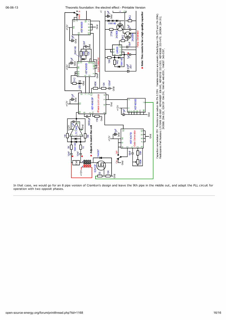
06-06-13 Theoretic foundation: the electret effect - Printable Version
16/16open-source-energy.org/forum/printthread.php?tid=1168
In that case, we would go for an 8 pipe version of Cramton's design and leave the 9th pipe in the middle out, and adapt the PLL circuit foroperation with two opposit phases.


