
theonlinephysicstutortheonlinephysicstutor.com/downloads/AQA Induction questions.pdf · measure the...
26
The figure below shows an end view of a simple electrical generator. A rectangular coil is rotated in a uniform magnetic field with the axle at right angles to the field direction. When in the position shown in the figure below the angle between the direction of the magnetic field and the normal to the plane of the coil is θ. (a) The coil has 50 turns and an area of 1.9 × 10 –3 m 2 . The flux density of the magnetic field is 2.8 × 10 –2 T. Calculate the flux linkage for the coil when θ is 35°, expressing your answer to an appropriate number of significant figures. answer = ...................................... Wb turns (3) 1 (b) The coil is rotated at constant speed, causing an emf to be induced. (i) Sketch a graph on the outline axes to show how the induced emf varies with angle θ during one complete rotation of the coil, starting when θ = 0. Values are not required on the emf axis of the graph. (1) (ii) Give the value of the flux linkage for the coil at the positions where the emf has its greatest values. answer = ...................................... Wb turns (1) Page 2 of 41 theonlinephysicstutor.com @TOPhysicsTutor facebook.com/TheOnlinePhysicsTutor
Transcript of theonlinephysicstutortheonlinephysicstutor.com/downloads/AQA Induction questions.pdf · measure the...

The figure below shows an end view of a simple electrical generator. A rectangular coil isrotated in a uniform magnetic field with the axle at right angles to the field direction. When in theposition shown in the figure below the angle between the direction of the magnetic field and thenormal to the plane of the coil is θ.
(a) The coil has 50 turns and an area of 1.9 × 10⁻³ m2. The flux density of the magnetic field is2.8 × 10–2 T. Calculate the flux linkage for the coil when θ is 35°, expressing your answer toan appropriate number of significant figures.
answer = ...................................... Wb turns(3)
1
(b) The coil is rotated at constant speed, causing an emf to be induced.
(i) Sketch a graph on the outline axes to show how the induced emf varies with angle θduring one complete rotation of the coil, starting when θ = 0. Values are not requiredon the emf axis of the graph.
(1)
(ii) Give the value of the flux linkage for the coil at the positions where the emf has itsgreatest values.
answer = ...................................... Wb turns(1)
Page 2 of 41
theonlinephysicstutor.com
@TOPhysicsTutor facebook.com/TheOnlinePhysicsTutor

(iii) Explain why the magnitude of the emf is greatest at the values of θ shown in youranswer to part (b)(i).
.............................................................................................................
.............................................................................................................
.............................................................................................................
.............................................................................................................
.............................................................................................................
.............................................................................................................
.............................................................................................................
.............................................................................................................(3)
(Total 8 marks)
A rectangular coil is rotating anticlockwise at constant angular speed with its axle at rightangles to a uniform magnetic field. Figure 1 shows an end-on view of the coil at a particularinstant.
Figure 1
(a) At the instant shown in Figure 1, the angle between the normal to the plane of the coil andthe direction of the magnetic field is 30°.
(i) State the minimum angle, in degrees, through which the coil must rotate from itsposition in Figure 1 for the emf to reach its maximum value.
angle ................................. degrees(1)
2
Page 3 of 41
theonlinephysicstutor.com
@TOPhysicsTutor facebook.com/TheOnlinePhysicsTutor
(ii) Calculate the minimum angle, in radians, through which the coil must rotate from itsposition in Figure 1 for the flux linkage to reach its maximum value.
angle ................................. radians(2)
(b) Figure 2 shows how, starting in a different position, the flux linkage through the coil varieswith time.
(i) What physical quantity is represented by the gradient of the graph shown in Figure2?
...............................................................................................................(1)
(ii) Calculate the number of revolutions per minute made by the coil.
revolutions per minute ..............................................(2)
Page 4 of 41
theonlinephysicstutor.com
@TOPhysicsTutor facebook.com/TheOnlinePhysicsTutor

Figure 2
Figure 3
(iii) Calculate the peak value of the emf generated.
peak emf ......................................... V(3)
(c) Sketch a graph on the axes shown in Figure 3 above to show how the induced emf varieswith time over the time interval shown in Figure 2.
(2)
Page 5 of 41
theonlinephysicstutor.com
@TOPhysicsTutor facebook.com/TheOnlinePhysicsTutor

(d) The coil has 550 turns and a cross-sectional area of 4.0 × 10⁻³m2.
Calculate the flux density of the uniform magnetic field.
flux density .......................................... T(2)
(Total 13 marks)
Figure 1
A circular coil of diameter 140 mm has 850 turns. It is placed so that its plane is perpendicular toa horizontal magnetic field of uniform flux density 45 mT, as shown in Figure 1.
(a) Calculate the magnetic flux passing through the coil when in this position.
......................................................................................................................
......................................................................................................................(2)
3
(b) The coil is rotated through 90° about a vertical axis in a time of 120 ms.
Calculate
(i) the change of magnetic flux linkage produced by this rotation,
.............................................................................................................
.............................................................................................................
Page 6 of 41
theonlinephysicstutor.com
@TOPhysicsTutor facebook.com/TheOnlinePhysicsTutor

(ii) the average emf induced in the coil when it is rotated.
.............................................................................................................
.............................................................................................................
.............................................................................................................(4)
(Total 6 marks)
A metal aircraft with a wing span of 42 m flies horizontally with a speed of 1000 km h–1 in adirection due east in a region where the vertical component of the flux density of the Earth’smagnetic field is 4.5 × 10⁻⁵ T.
(a) Calculate the flux cut per second by the wings of the aircraft.
........................................................................................................................
........................................................................................................................
........................................................................................................................
........................................................................................................................
4
(b) Determine the magnitude of the potential difference between the wing tips, stating the lawwhich you are applying in this calculation.
........................................................................................................................
........................................................................................................................
........................................................................................................................
(c) What would be the change in the potential difference, if any, if the aircraft flew due west?
........................................................................................................................
........................................................................................................................(Total 6 marks)
Page 7 of 41
theonlinephysicstutor.com
@TOPhysicsTutor facebook.com/TheOnlinePhysicsTutor
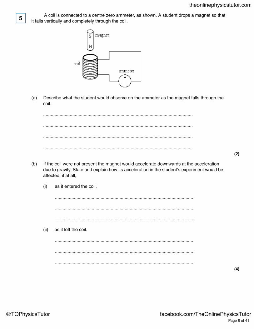
A coil is connected to a centre zero ammeter, as shown. A student drops a magnet so thatit falls vertically and completely through the coil.
(a) Describe what the student would observe on the ammeter as the magnet falls through thecoil.
......................................................................................................................
......................................................................................................................
......................................................................................................................
......................................................................................................................(2)
5
(b) If the coil were not present the magnet would accelerate downwards at the accelerationdue to gravity. State and explain how its acceleration in the student’s experiment would beaffected, if at all,
(i) as it entered the coil,
.............................................................................................................
.............................................................................................................
.............................................................................................................
(ii) as it left the coil.
.............................................................................................................
.............................................................................................................
.............................................................................................................(4)
Page 8 of 41
theonlinephysicstutor.com
@TOPhysicsTutor facebook.com/TheOnlinePhysicsTutor

(c) Suppose the student forgot to connect the ammeter to the coil, therefore leaving the circuitincomplete, before carrying out the experiment. Describe and explain what difference thiswould make to your conclusions in part (b).
You may be awarded marks for the quality of written communication provided in youranswer.
......................................................................................................................
......................................................................................................................
......................................................................................................................
......................................................................................................................
......................................................................................................................(3)
(Total 9 marks)
Page 9 of 41
theonlinephysicstutor.com
@TOPhysicsTutor facebook.com/TheOnlinePhysicsTutor

Figure 1 shows an arrangement for investigating electromagnetic induction.
Figure 1
When the switch is closed there is a current in the coil in circuit X. The current is in a clockwisedirection as viewed from position P.
Circuit Y is viewed from position P.
(a) Explain how Lenz’s law predicts the direction of the induced current when the switch isopened and again when it is closed.
........................................................................................................................
........................................................................................................................
........................................................................................................................
........................................................................................................................
........................................................................................................................
........................................................................................................................
........................................................................................................................
........................................................................................................................
........................................................................................................................
........................................................................................................................
........................................................................................................................
........................................................................................................................(4)
6
Page 10 of 41
theonlinephysicstutor.com
@TOPhysicsTutor facebook.com/TheOnlinePhysicsTutor
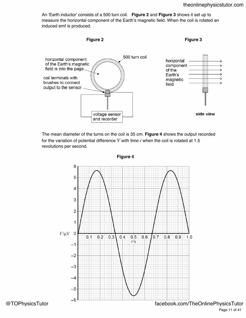
An ‘Earth inductor’ consists of a 500 turn coil. Figure 2 and Figure 3 shows it set up tomeasure the horizontal component of the Earth’s magnetic field. When the coil is rotated aninduced emf is produced.
Figure 2 Figure 3
The mean diameter of the turns on the coil is 35 cm. Figure 4 shows the output recordedfor the variation of potential difference V with time t when the coil is rotated at 1.5revolutions per second.
Figure 4
Page 11 of 41
theonlinephysicstutor.com
@TOPhysicsTutor facebook.com/TheOnlinePhysicsTutor
(b) Determine the flux density, BH, of the horizontal component of the Earth’s magnetic field.
horizontal component of flux density = _____________T(3)
(Total 7 marks)
(a) State Lenz’s law.
........................................................................................................................
........................................................................................................................
........................................................................................................................
........................................................................................................................(2)
7
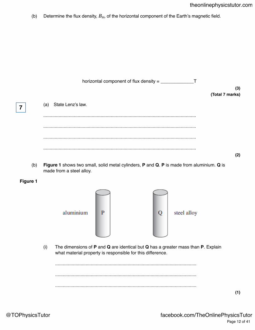
(b) Figure 1 shows two small, solid metal cylinders, P and Q. P is made from aluminium. Q ismade from a steel alloy.
Figure 1
(i) The dimensions of P and Q are identical but Q has a greater mass than P. Explainwhat material property is responsible for this difference.
...............................................................................................................
...............................................................................................................
...............................................................................................................(1)
Page 12 of 41
theonlinephysicstutor.com
@TOPhysicsTutor facebook.com/TheOnlinePhysicsTutor
(ii) When P and Q are released from rest and allowed to fall freely through a verticaldistance of 1.0 m, they each take 0.45 s to do so. Justify this time value and explainwhy the times are the same.
...............................................................................................................
...............................................................................................................
...............................................................................................................
...............................................................................................................
...............................................................................................................
...............................................................................................................(2)
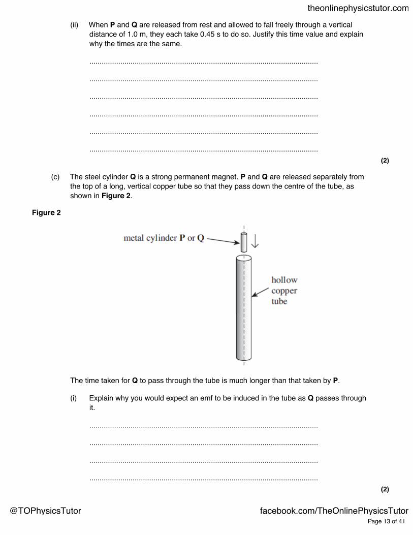
(c) The steel cylinder Q is a strong permanent magnet. P and Q are released separately fromthe top of a long, vertical copper tube so that they pass down the centre of the tube, asshown in Figure 2.
Figure 2
The time taken for Q to pass through the tube is much longer than that taken by P.
(i) Explain why you would expect an emf to be induced in the tube as Q passes throughit.
...............................................................................................................
...............................................................................................................
...............................................................................................................
...............................................................................................................(2)
Page 13 of 41
theonlinephysicstutor.com
@TOPhysicsTutor facebook.com/TheOnlinePhysicsTutor

(ii) State the consequences of this induced emf, and hence explain why Q takes longerthan P to pass through the tube.
...............................................................................................................
...............................................................................................................
...............................................................................................................
...............................................................................................................
...............................................................................................................
...............................................................................................................
...............................................................................................................
...............................................................................................................(3)
(d) The copper tube is replaced by a tube of the same dimensions made from brass. Theresistivity of brass is much greater than that of copper. Describe and explain how, if at all,the times taken by P and Q to pass through the tube would be affected.
P: ...................................................................................................................
........................................................................................................................
........................................................................................................................
........................................................................................................................
Q: ...................................................................................................................
........................................................................................................................
........................................................................................................................
........................................................................................................................(3)
(Total 13 marks)
Page 14 of 41
theonlinephysicstutor.com
@TOPhysicsTutor facebook.com/TheOnlinePhysicsTutor
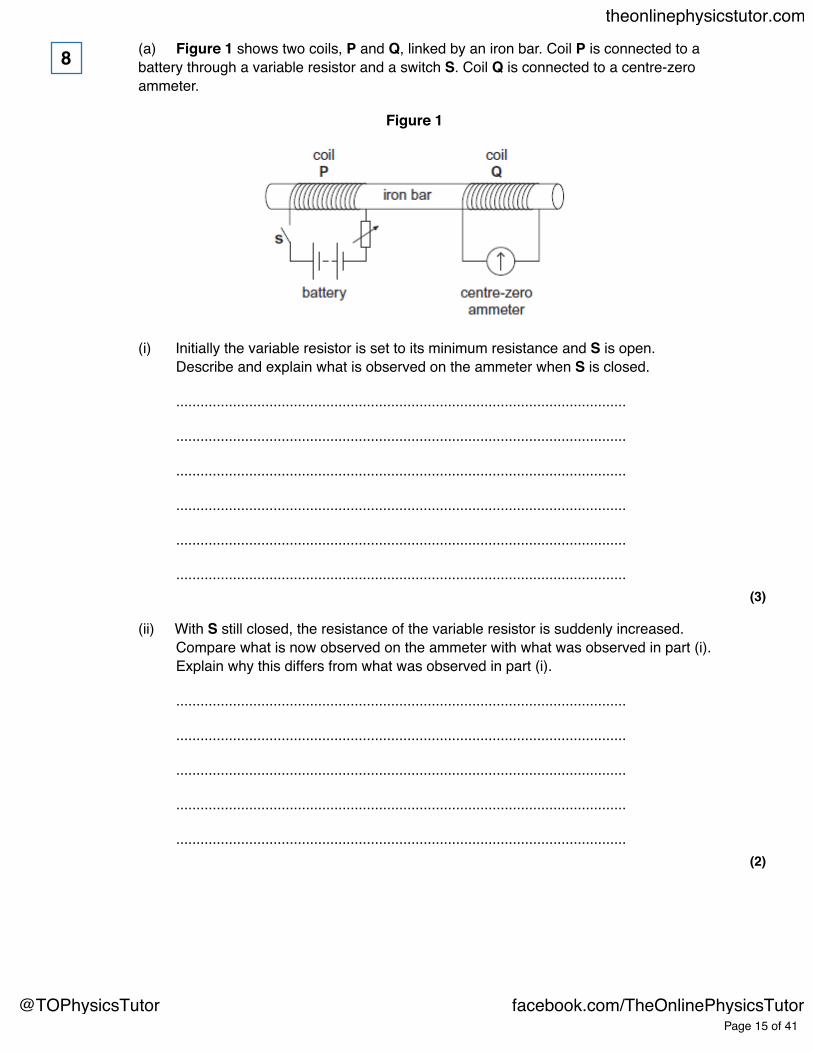
(a) Figure 1 shows two coils, P and Q, linked by an iron bar. Coil P is connected to abattery through a variable resistor and a switch S. Coil Q is connected to a centre-zeroammeter.
Figure 1
8
(i) Initially the variable resistor is set to its minimum resistance and S is open.Describe and explain what is observed on the ammeter when S is closed.
...............................................................................................................
...............................................................................................................
...............................................................................................................
...............................................................................................................
...............................................................................................................
...............................................................................................................(3)
(ii) With S still closed, the resistance of the variable resistor is suddenly increased.Compare what is now observed on the ammeter with what was observed in part (i).Explain why this differs from what was observed in part (i).
...............................................................................................................
...............................................................................................................
...............................................................................................................
...............................................................................................................
...............................................................................................................(2)
Page 15 of 41
theonlinephysicstutor.com
@TOPhysicsTutor facebook.com/TheOnlinePhysicsTutor
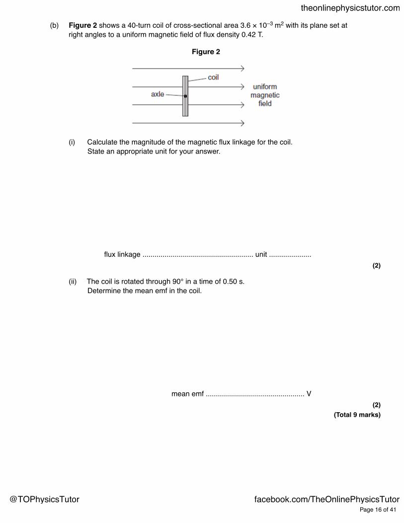
(b) Figure 2 shows a 40-turn coil of cross-sectional area 3.6 × 10⁻³ m2 with its plane set atright angles to a uniform magnetic field of flux density 0.42 T.
Figure 2
(i) Calculate the magnitude of the magnetic flux linkage for the coil.State an appropriate unit for your answer.
flux linkage ....................................................... unit .....................(2)
(ii) The coil is rotated through 90° in a time of 0.50 s.Determine the mean emf in the coil.
mean emf ................................................. V(2)
(Total 9 marks)
Page 16 of 41
theonlinephysicstutor.com
@TOPhysicsTutor facebook.com/TheOnlinePhysicsTutor

(a) A satellite moves in a circular orbit at constant speed. Explain why its speed does notchange even though it is acted on by a force.
........................................................................................................................
........................................................................................................................
........................................................................................................................
........................................................................................................................
........................................................................................................................
........................................................................................................................(3)
9
(b) At a certain point along the orbit of a satellite in uniform circular motion, the Earth’smagnetic flux density has a component of 56 μT towards the centre of the Earth and acomponent of 17 μT in a direction perpendicular to the plane of the orbit.
(i) Calculate the magnitude of the resultant magnetic flux density at this point.
...............................................................................................................
...............................................................................................................
(ii) The satellite has an external metal rod pointing towards the centre of the Earth.Calculate the angle between the direction of the resultant magnetic field and the rod.
...............................................................................................................
...............................................................................................................
...............................................................................................................
...............................................................................................................
...............................................................................................................
Page 17 of 41
theonlinephysicstutor.com
@TOPhysicsTutor facebook.com/TheOnlinePhysicsTutor

(iii) Explain why an emf is induced in the rod in this position.
...............................................................................................................
...............................................................................................................(4)
(Total 7 marks)
The diagram below shows the main parts of a geophone.10
Page 18 of 41
theonlinephysicstutor.com
@TOPhysicsTutor facebook.com/TheOnlinePhysicsTutor
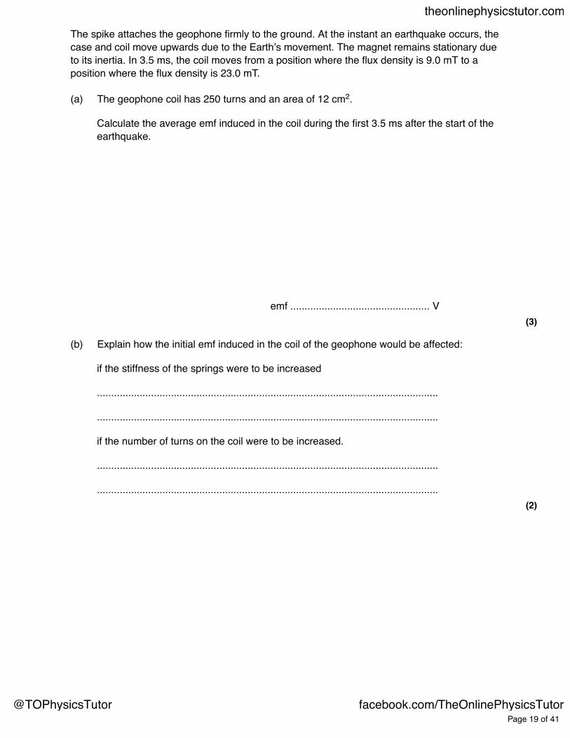
The spike attaches the geophone firmly to the ground. At the instant an earthquake occurs, thecase and coil move upwards due to the Earth’s movement. The magnet remains stationary dueto its inertia. In 3.5 ms, the coil moves from a position where the flux density is 9.0 mT to aposition where the flux density is 23.0 mT.
(a) The geophone coil has 250 turns and an area of 12 cm2.
Calculate the average emf induced in the coil during the first 3.5 ms after the start of theearthquake.
emf ................................................. V(3)
(b) Explain how the initial emf induced in the coil of the geophone would be affected:
if the stiffness of the springs were to be increased
........................................................................................................................
........................................................................................................................
if the number of turns on the coil were to be increased.
........................................................................................................................
........................................................................................................................(2)
Page 19 of 41
theonlinephysicstutor.com
@TOPhysicsTutor facebook.com/TheOnlinePhysicsTutor
(c) (i) The geophone’s magnet has a mass of 8.0 × 10 –3 kg and the spring stiffness of thesystem is 2.6 N m–1.
Show that the natural period of oscillation of the mass−spring system isapproximately 0.35 s.
(2)
(ii) At the instant that the Earth stops moving after one earthquake, the emf in the coil isat its maximum value of +8 V. The magnet continues to oscillate.
On the grid below, sketch a graph showing the variation of emf with time as themagnet’s oscillation decays.Show at least three oscillations.
Page 20 of 41
theonlinephysicstutor.com
@TOPhysicsTutor facebook.com/TheOnlinePhysicsTutor

(3)(Total 10 marks)
(a) State, in words, the two laws of electromagnetic induction.
Law 1 .....................................................................................................................
.............................................................................................................................
.............................................................................................................................
.............................................................................................................................
Law 2 .....................................................................................................................
.............................................................................................................................
.............................................................................................................................
.............................................................................................................................(3)
11
Page 21 of 41
theonlinephysicstutor.com
@TOPhysicsTutor facebook.com/TheOnlinePhysicsTutor

(b) The diagram below illustrates the main components of one type of electromagnetic brakingsystem. A metal disc is attached to the rotating axle of a vehicle. An electromagnet ismounted with its pole pieces placed either side of the rotating disc, but not touching it.When the brakes are applied, a direct current is passed through the coil of theelectromagnet and the disc slows down.
(i) Explain, using the laws of electromagnetic induction, how the device in the diagramacts as an electromagnetic brake.
...................................................................................................................
...................................................................................................................
...................................................................................................................
...................................................................................................................
...................................................................................................................
...................................................................................................................
...................................................................................................................
...................................................................................................................
...................................................................................................................
...................................................................................................................(3)
Page 22 of 41
theonlinephysicstutor.com
@TOPhysicsTutor facebook.com/TheOnlinePhysicsTutor
(ii) A conventional braking system has friction pads that are brought into contact with amoving metal surface when the vehicle is to be slowed down.State one advantage and one disadvantage of an electromagnetic brake comparedto a conventional brake.
Advantage ..................................................................................................
...................................................................................................................
...................................................................................................................
Disadvantage .............................................................................................
...................................................................................................................
...................................................................................................................(2)
(Total 8 marks)
Page 23 of 41
theonlinephysicstutor.com
@TOPhysicsTutor facebook.com/TheOnlinePhysicsTutor
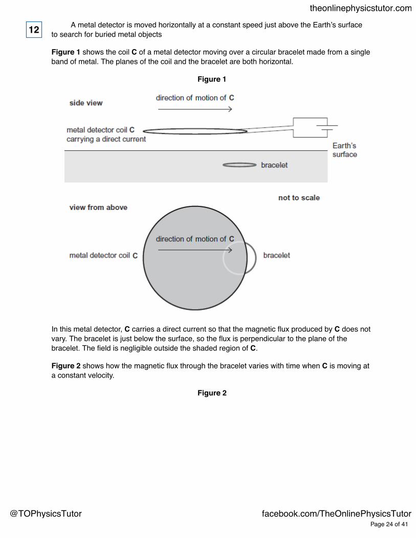
A metal detector is moved horizontally at a constant speed just above the Earth’s surfaceto search for buried metal objects
Figure 1 shows the coil C of a metal detector moving over a circular bracelet made from a singleband of metal. The planes of the coil and the bracelet are both horizontal.
Figure 1
In this metal detector, C carries a direct current so that the magnetic flux produced by C does notvary. The bracelet is just below the surface, so the flux is perpendicular to the plane of thebracelet. The field is negligible outside the shaded region of C.
Figure 2 shows how the magnetic flux through the bracelet varies with time when C is moving ata constant velocity.
Figure 2
12
Page 24 of 41
theonlinephysicstutor.com
@TOPhysicsTutor facebook.com/TheOnlinePhysicsTutor

(a) (i) Sketch a graph on the grid to show how the emf induced in the bracelet varies withtime as C moves across the bracelet. Use the same scale on the time axis as inFigure 2.
(3)
Page 25 of 41
theonlinephysicstutor.com
@TOPhysicsTutor facebook.com/TheOnlinePhysicsTutor

(ii) Use the laws of Faraday and Lenz to explain the shape of your graph.
...................................................................................................................
...................................................................................................................
...................................................................................................................
...................................................................................................................
...................................................................................................................
...................................................................................................................
...................................................................................................................
...................................................................................................................
...................................................................................................................
...................................................................................................................(4)
(b) The velocity at which C is moved is 0.28 m s−1.
Show that the diameter of the bracelet is about 6 cm.
(1)
Page 26 of 41
theonlinephysicstutor.com
@TOPhysicsTutor facebook.com/TheOnlinePhysicsTutor

(c) Determine the magnetic flux density of the field produced by C at the position of thebracelet.
magnetic flux density ........................... T(2)
(d) Determine the maximum emf induced in the bracelet.
maximum emf ........................... V(3)
(Total 13 marks)
Page 27 of 41
theonlinephysicstutor.com
@TOPhysicsTutor facebook.com/TheOnlinePhysicsTutor