THEMIS MISSION PDRESA- 1 UCB, November, 2003 ESA Plasma Instrument Mission PDR Dr. C. W. Carlson and...
20
THEMIS MISSION PDR ESA-1 UCB, November, 2003 ESA Plasma Instrument Mission PDR Dr. C. W. Carlson and Themis ESA Team UC Berkeley SSL
-
Upload
chastity-willis -
Category
Documents
-
view
220 -
download
0
Transcript of THEMIS MISSION PDRESA- 1 UCB, November, 2003 ESA Plasma Instrument Mission PDR Dr. C. W. Carlson and...
THEMIS MISSION PDR ESA-1 UCB, November, 2003
ESA Plasma InstrumentMission PDR
Dr. C. W. Carlson and Themis ESA TeamUC Berkeley SSL

THEMIS MISSION PDR ESA-2 UCB, November, 2003
Overview
ESA Plasma Instrument
• Requirements & Specifications
• Heritage
• Design Overview
• Block Diagram
• Component Descriptions
• Mechanical and Thermal
• Mass and Power
• Test and Calibration

THEMIS MISSION PDR ESA-3 UCB, November, 2003
Requirements and Specifications
Measurement
• The ESA instrument measures 3-D electron and ion energy distribution functions over the Energy range 10 eV to 30 keV. Typical energy sweep has 16 or 32 energy samples• A full 4-pi distribution measurement is produced during each spin• Sweep rate of 32/spin gives dense sample of 3-D particle distributions• Raw measurements are compressed to selectable “reduced distributions” and moments
Implementation
• Ion and electron “top-hat” electrostatic analyzers have 180 degree field of view• Field of view is divided into 8 electron and 16 ion elevation bins• Plasma analyzers have hardware programmed functions: sweep rate, sweep waveform, energy range, data collection rates. These functions are set by command.• Higher level data formatting and computed products are carried out in the ETC board.• Energy sweep is exponential with programmable starting energy and step ratio

THEMIS MISSION PDR ESA-4 UCB, November, 2003
Heritage
ESA Instrument Design is based on FAST plasma instrument
• Nearly identical measurement requirements
• Well proven design – all 16 FAST ESA detectors remain fully functional after 7 years in orbit (Design requirement was 3 years in high radiation environment)
• Flight hardware designs and calibration facilities can be used with minor changes
• Flight spare components are available for critical functions. Design will use existing ACTEL 1020 gate array components.
• THEMIS instrument uses FAST strategy of “dumb” sensor having hardware defined measurement modes, combined with a “smart” processor-based interface board that performs data formatting and higher level computations. The ETC board provides this intermediate processing for both the ESA and SST.
THEMIS MISSION PDR ESA-5 UCB, November, 2003
REQUIREMENT ESA DESIGN
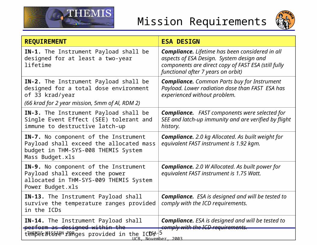
IN-1. The Instrument Payload shall be designed for at least a two-year lifetime
Compliance. Lifetime has been considered in all aspects of ESA Design. System design and components are direct copy of FAST ESA (still fully functional after 7 years on orbit)
IN-2. The Instrument Payload shall be designed for a total dose environment of 33 krad/year
(66 krad for 2 year mission, 5mm of Al, RDM 2)
Compliance. Common Parts buy for Instrument Payload. Lower radiation dose than FAST ESA has experienced without problem.
IN-3. The Instrument Payload shall be Single Event Effect (SEE) tolerant and immune to destructive latch-up
Compliance. FAST components were selected for SEE and latch-up immunity and are verified by flight history.
IN-7. No component of the Instrument Payload shall exceed the allocated mass budget in THM-SYS-008 THEMIS System Mass Budget.xls
Compliance. 2.0 kg Allocated. As built weight for equivalent FAST instrument is 1.92 kgm.
IN-9. No component of the Instrument Payload shall exceed the power allocated in THM-SYS-009 THEMIS System Power Budget.xls
Compliance. 2.0 W Allocated. As built power for equivalent FAST instrument is 1.75 Watt.
IN-13. The Instrument Payload shall survive the temperature ranges provided in the ICDs
Compliance. ESA is designed and will be tested to comply with the ICD requirements.
IN-14. The Instrument Payload shall perform as designed within the temperature ranges provided in the ICDs
Compliance. ESA is designed and will be tested to comply with the ICD requirements.
Mission Requirements

THEMIS MISSION PDR ESA-6 UCB, November, 2003
REQUIREMENT ESA DESIGN
IN-16 The Instrument Payload shall comply with the Magnetics Cleanliness standard described in the THEMIS Magnetics Control Plan
Compliance. THM-SYS-002 Magnetics Contamination Control Plan.
IN-17 The Instrument Payload shall comply with the THEMIS Electrostatic Cleanliness Plan
Compliance. THM-SYS-003 Electrostatic Cleanliness Plan
IN-18 The Instrument Payload shall comply with the THEMIS Contamination Control Plan
Compliance. THM-SYS-004 Contamination Control Plan
IN-19. All Instruments shall comply with all electrical specifications
Compliance. THM-IDPU-001 Backplane Specification.
IN-20. The Instrument Payload shall be compatible per IDPU-Instrument ICDs
Compliance. THM-SYS-105 ESA and SST Electronics Card (ETC) Specification. Verification Matrices to be completed.
IN-21. The Instrument Payload shall be compatible per the IDPU-Probe Bus ICD
Compliance. THM-SYS-101 IDPU/ESA-to-Probe ICD. Verification Matrices to be completed.
IN-23 The Instrument Payload shall verify performance requirements are met per the THEMIS Verification Plan and Environmental Test Spec.
Compliance. THM-SYS-005 Verification Plan and Environmental Test Specification preliminary draft. Verification matrix to be completed.
IN-24 The Instrument Payload shall survive and function prior, during and after exposure to the environments described in the THEMIS Verification Plan and Environmental Test Specification
Compliance. THM-SYS-005 Verification Plan and Environmental Test Specification preliminary draft. Verification matrix to be completed.
Mission Requirements

THEMIS MISSION PDR ESA-7 UCB, November, 2003
REQUIREMENT ESA DESIGN
IN.ESA-1. The ESA shall obtain partial moments of the 3D plasma electron and ion distributions in the magnetotail plasma sheet
Compliance. ESA will provide the ETC board with plasma measurement data sufficient for computing the required moments.
IN.ESA-2. The ESA shall measure differences in velocity and ion pressure between probes in the magnetotail plasma sheet
Compliance. ESA will provide the ETC board with plasma measurement data sufficient for computing the required moments.
IN.ESA-3. The ESA shall measure ion and electron distributions that are associated with the current disruption process
Compliance. ESA will provide the ETC board with plasma measurement data sufficient for computing the required moments.
IN.ESA-4. The ESA shall be capable of measuring ion moments and differences of those moments in the magnetosheath and solar wind.
Compliance. ESA will provide the ETC board with plasma measurement data sufficient for computing the required moments. Solar wind moments will be limited to a specific range of velocity and density consistent with instrument saturation.
Science Requirements

THEMIS MISSION PDR ESA-8 UCB, November, 2003
REQUIREMENT ESA DESIGN
IN.ESA-5. The ESA shall measure ions and electrons over an energy range of 10eV to 30 keV
Compliance. Satisfied by design.
IN.ESA-6. The ESA energy sampling resolution, dE/E, shall be better than 25% FWHM for ions and electrons
Compliance. Satisfied by design.
IN.ESA-7. The ESA shall be capable of measuring ion and electron energy flux of 10^4 to 10^9 keV/cm^2/s/Str/keV
Compliance. Satisfied by design.
IN.ESA-8. The ion ESA geometric factor shall be attenuated in the solar wind to avoid saturation.
Compliance. High fluxes of solar wind ions will be accommodated by small area anodes in the equatorial view directions.
IN.ESA-9. The ESA shall supply partial energy moments at one spin time resolution.
Compliance. Satisfied by design.
IN.ESA-10. The ESA shall have a 180 deg. elevation FOV with a minimum angular resolution of 22.5 deg.
Compliance. Satisfied by design.
IN.ESA-11. To resolve the solar wind, the ESA shall have a FOV with enhanced resolution of ~ 6 deg.
Compliance. Satisfied by design.
IN.ESA-12. The ESA shall produce measurements of particle distributions over the entire 4pi steradian field of view in one spin period.
Compliance. Satisfied by design.
IN.ESA-13. ESA calibration shall ensure <20% relative flux uncertainty (not including statistical uncertainty) over the ranges defined above.
Compliance. Satisfied by on-orbit calibration of plasma density with wave measurements.
Performance Requirements

THEMIS MISSION PDR ESA-9 UCB, November, 2003
ESA Development Team
ESA Systems• Definition and Specifications: Charles Carlson, UCB• Analog and Digital Systems: Charles Carlson, UCB• Mechanical and Thermal: Bill Elliot, Paul Turin• Ground Support Equipment: Jim Lewis, UCB• Power Systems (LVPS, HVPS): Peter Berg, UCB• Thermal: Chris Smith, UCB• Calibration and Test Facilities: Mario Marckwordt, UCB• IDPU Instrument Interface: Robert Abiad• Flight Software: Frank Harvey, UCB
ESA Support Functions• Probe Interfaces: Ellen Taylor, UCB• Reliability and Quality Assurance (R&QA): Ron Jackson, UCB• Parts Engineering: Jorg Fischer, UCB

THEMIS MISSION PDR ESA-10 UCB, November, 2003
Design Overview
THEMIS Uses FAST ESA Design(1/2 of a FAST module)
• Modular for efficient testing, assembly and repair
• Entrance sealed and nitrogen purged
Changes from FAST:• Ion Detector Anode pattern• Cover Release Mechanism (TiNi Nanomuscle-125)
Specifications:• 180 degree elevation field of view
with a minimum angular resolution of 22.5 degrees.
• To resolve the solar wind the IESA will have a field of view with enhanced resolution of approximately 5.62 degrees.
Pulse Amplifiers
Digital Interface
& HV Sweep
HV Supplies
}
MCP

THEMIS MISSION PDR ESA-11 UCB, November, 2003
Block Diagram
• Electronics design is nearly direct copy from FAST• Three circuit modules plug together for efficient assembly and test• MCP pulse amplifiers are Amptek A121 with programmable gain• All discrete logic, counters, and HV DAC drivers are Actel FPGAs• HV supplies are a mature design built at UCBSSL

THEMIS MISSION PDR ESA-12 UCB, November, 2003
Analyzer/Anode/Preamp
FAST ESA module
Themis will use FAST module design
• IESA/EESA Analyzers Analyzer deflection plates Aperture closer mechanism UV rejection Cu-Black coating Nitrogen purge system
• Anode Boards Mounts MCPs HV Interface connectors HV coupling capacitors
• Preamp Board AMPTEK A121 preamps Actel logic arrays Anode and Logic board interfaces
THEMIS MISSION PDR ESA-13 UCB, November, 2003
MCP/Anode Board Assembly
Top Bottom
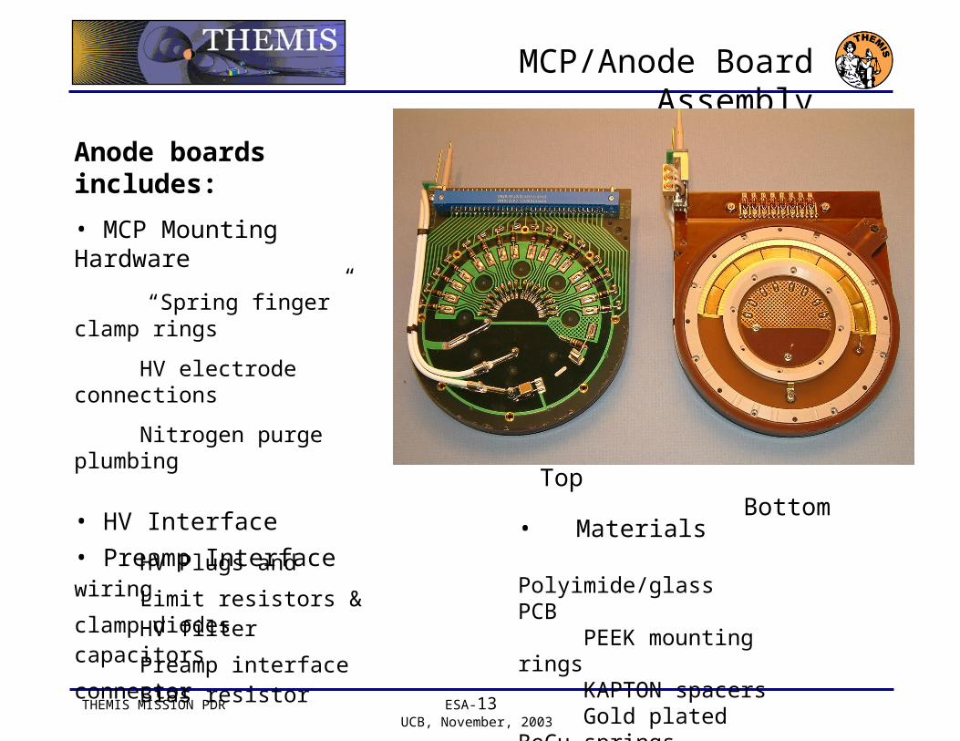
Anode boards includes:
• MCP Mounting Hardware
“Spring finger” clamp rings
HV electrode connections
Nitrogen purge plumbing
• HV Interface
HV Plugs and wiring
HV filter capacitors
Bias resistor
• Preamp Interface
Limit resistors & clamp diodes
Preamp interface connector
• Materials Polyimide/glass PCB PEEK mounting rings KAPTON spacers Gold plated BeCu springs

THEMIS MISSION PDR ESA-14 UCB, November, 2003
MCP Preamp/Accumulator
Preamp board includes:
• 24 AMPTEK A121 hybrid preamps
• 3 Actel logic arrays contain:
24 x 14 bit accumulators
Command/Data Interface
Command interpreter
Test pulse generator
Commandable selective anode blocking
• MCP Anode board interface
• Radiation “spot shielding” for preamps

THEMIS MISSION PDR ESA-15 UCB, November, 2003
HV Sweep & Digital Interface
HV Sweep/ Interface board includes:
• Main data interface to ETC board and IDPU power board
• HV fixed and sweep supply control
• HV Sweep waveform generator (Amptek HV-601 high voltage optocouplers)
• Housekeeping multiplexer
• Plug-in interface to anodes and HV supplies
FAST Sweep/Interface Board
Themis board is about 30 % shorter length

THEMIS MISSION PDR ESA-16 UCB, November, 2003
FAST HV Supply Assembly
FAST HV Interface Board
(mounts on back side of Sweep/Interface board)
Themis board is about 30 % shorter length
HV Assembly board includes:
• Four HV supplies with interface mother board (FAST example has 6 supplies)
• HV supply assembly and Digital interface boards share structural mount plate
• HV supplies have HV sockets that mate directly with HV plugs on HV sweep board and on anodes.
• Themis option may share a single positive/negative raw supply, reducing total requirement to 3 supplies. Decision pending prototype test and risk evaluation

THEMIS MISSION PDR ESA-17 UCB, November, 2003
HV Supply and VMI Multiplier
A single FAST HV Supply shown with a sample FAST HV multiplier module and a candidate commercial replacement module from VMI (HM402N10). A total of 25 HV supplies on FAST have operated without incident for seven years.
The VMI multiplier is an attractive replacement for the SSL fabricated component:• Huge saving of in-house technician work• VMI part has been tested for use on STEREO• The multiplier is physically and electrically compatible with existing FAST design• VMI part is smaller – will allow single plus/minus supply for raw sweep source

THEMIS MISSION PDR ESA-18 UCB, November, 2003
ESA S/C Interface Requirements
Interface to Spacecraft• ESA Mounts to IDPU (0.12
Watts/deg C Coupling)• Thermal Joint TBD• “Foot” Mounts to Bus• ESA Extends Through Corner
Panel With Clearance and Some Sort of Radiation Closeout
• Constrained By 3.25” Furthermost Stand-Off of the ESA from the Corner Panel
• ESA Should Be Very Close to the Middle (Top to Bottom) of the Corner Panel (Science Requirement)

THEMIS MISSION PDR ESA-19 UCB, November, 2003
Thermal - ESA
Temperature Limits
•Predictions from Swales
•Cold prediction from 3 hour eclipse orbit
•Hot prediction from hottest orbit and attitude
•Average operating temperature around 30 °C
•Better predictions await more complete instrument thermal models
Survival (°C)Predictions
(°C)
Margin
(°C)Eclipse-Op
Science-Op Cold Hot Cold Hot
-50 -30 40 +65 -17 8 13 32

THEMIS MISSION PDR ESA-20 UCB, November, 2003
Test and Calibration
• UCBSSL has automated calibration facilities (FAST, WIND heritage) that will be used for THEMIS ESA calibrations
• Facility uses cryogenic pumped vacuum chambers with computer controlled ion and
electron guns and 3-axis manipulators
• All six ESA units (5 flight/ 1 spare) use identical calibration procedures adapted from FAST
• Full environmental testing (Thermal / Vacuum, EMC, Vibration)
3 Axis Manipulator
Calibration Chamber