
The!Accord!on!Fire!and!Building!Safety!in!Bangladesh...
79
The Accord on Fire and Building Safety in Bangladesh Building Standard V1.1 August 12, 2014
Transcript of The!Accord!on!Fire!and!Building!Safety!in!Bangladesh...

The Accord on Fire and Building Safety in Bangladesh
Building Standard
V1.1
August 12, 2014


Page iii
TABLE OF CONTENTS
1 Part 1 Scope and Definitions ................................................................................................................................ 1
2 Part 2 Administration and Enforcement .............................................................................................................. 5
3 Part 3 General Building Requirements ................................................................................................................. 6
4 Part 4 Fire Protection Construction .................................................................................................................... 11
5 Part 5 Fire Protection Systems ........................................................................................................................... 16
6 Part 6 Means of Egress ....................................................................................................................................... 21
7 Part 7 Building Materials .................................................................................................................................... 31
8 Part 8 Structural Design ...................................................................................................................................... 33
9 Part 9 Construction Practices and Safety ........................................................................................................... 47
10 Part 10 Building Services (MEP) .......................................................................................................................... 50
11 Part 11 Alterations/Change of Use ..................................................................................................................... 71
12 Part 12 Existing Buildings ................................................................................................................................... 73
13 Part 13 Human Element Programs ..................................................................................................................... 74
NOTICE: Revised sections are indicated by a vertical rule beside the paragraph, table, or figure in which the change occurred. These rule are provided as an aid to the user in identifying changes from the previous edition. Where one or more complete paragraphs have been deleted, the deletion is indicated by a bullet (�) between the paragraphs that remain.

Part 1 Scope and Definitions
1
1 Part 1 Scope and Definitions
1.1 Scope.
1.1.1 Title. The Building Standard developed by the Accord for Fire and Building Safety in Bangladesh shall be referred to herein as “the Standard” or “this Standard.”
1.1.2 Danger to Life from Fire. This Standard addresses and establishes minimum criteria to minimize danger to life from the effects of fire including smoke, heat, and toxic gases created during a fire.
1.1.3 Danger to Life from Structural Collapse. This Standard addresses and establishes minimum criteria for the evaluation and protection from danger to life from building collapse.
1.1.4 Danger to Life from Electrical Hazards. This Standard addresses and establishes minimum criteria for the protection from danger to life from electrical hazards.
1.2 Application.
1.2.1.1 This Standard shall apply to the construction, addition, alteration, movement, enlargement, replacement, repair, installation of major equipment, use and occupancy, maintenance, removal, and demolition of all buildings and structures used for producing readymade garments for Accord signatory brands in Bangladesh. All other requirements from BNBC Part 2 Section 1.4 shall apply.
1.2.1.2 This Standard shall apply to both new construction and existing buildings and structures as specifically outlined in this Standard.
1.3 Purpose. The purpose of this Standard is establish a common set of minimum requirements that provide a uniform and effective method for assessing fire and building structural safety in new and existing readymade garment factories utilized by Accord suppliers.
1.4 Disclaimer. The technical requirements of this Standard are intended for use by professional structural engineers, fire protection specialists, and electrical engineers who are competent to evaluate the significance and limitation of its content.
1.5 Definitions. All definitions as stated in BNBC apply to this Standard, except as specifically supplemented or changed herein. Additional definitions are provided within each part of this Standard.
1.5.1 Accord Supplier. A ready-‐made garment supplier or subcontractor who is producing garments or products for an Accord signatory brand.
1.5.2 Accord. Means the Accord for Fire and Building Safety in Bangladesh.
1.5.3 Chief Safety Inspector (CSI). Means the Chief Safety Inspector of the Accord on Fire and Building Safety in Bangladesh.
1.6 References.
1.6.1 General. The documents listed in this section are referenced in this Standard and the portions thereof are considered part of the requirements of this Standard to the extent of each such reference.
1.6.2 Bangladesh National Building Code (BNBC). The 2006 BNBC was enacted into Bangladesh Law on November 16, 2006.
1.6.3 Bangladesh Laws and Rules.

Part 1 Scope and Definitions
2
1.6.3.1 Electricity Act, 1910.
1.6.3.2 Electricity Rules, 1937.
1.6.3.3 Boiler Act, 1923, Section 2 (b) and 6
1.6.3.4 Petroleum Act, 1934
1.6.3.5 Building Construction Act, 1952
1.6.3.6 Fire Service Rules 1961
1.6.3.7 Factories Rules, 1979, Sections 3 (1), 4, 41, 43, 51, and 52
1.6.3.8 Statutory Regulatory Orders (S.R.O) 109, Act 1999, published on 25th May
1.6.3.9 Fire Resist and Extinguish Act 2003
1.6.3.10 Bangladesh Labour Act, 2006 as amended by Bangladesh Labour (Amendment) Act, 2013.
1.6.3.11 Dhaka Mahanagar Imarat Nirman Bidhimala 2008
1.6.3.12 Chittagong Imarat Nireman Bidhimala 2008
1.6.3.13 Circular _Building Permit on 19 August 2010, Ministry of Housing & Public Works/Pari – 1/Occupant-‐RMG 42/2007/256, circular no Ministry of Housing & Public works/Pari – 1/Occupant-‐RMG 42/2007/302 dated on 25 November 2008
1.6.3.14 Circular_ Removal of temporary tin shade from Rooftop of RMG Factory Buildings. REF: BGMEA Letter # BGA/Safety/18000/2011/28180, Dated: 28th December, 2011
1.6.3.15 Circular on 19 Apr 2013_RAJUK_Building Permit inside Detailed Area Plan (DAP)
1.6.4 ICC publications. International Code Council, 5203 Leesburg Pike, Suite 600, Falls Church, VA 22041 USA.
1.6.4.1 IBC, International Building Code, 2012.
1.6.4.2 IFC, International Fire Code, 2012.
1.6.4.3 IEBC, International Existing Building Code, 2012.
1.6.5 NFPA publications. National Fire Protection Association, 1 Battery march Park, Quincy, MA 02169-‐7471 USA.
1.6.5.1 NFPA 10, Standard for Portable Fire Extinguishers, 2013.
1.6.5.2 NFPA 13, Standard for the Installation of Sprinkler Systems, 2013.
1.6.5.3 NFPA 14, Standard for the Installation of Standpipe and Hose Systems, 2013.
1.6.5.4 NFPA 20, Standard for the Installation of Stationary Pumps for Fire Protection, 2013.
1.6.5.5 NFPA 22, Water Tanks for Private Fire Protection, 2013.
Part 1 Scope and Definitions
3
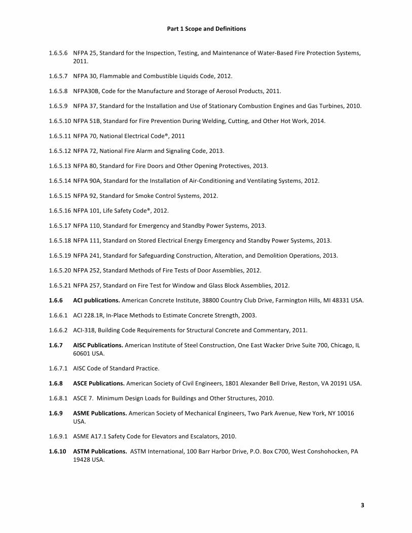
1.6.5.6 NFPA 25, Standard for the Inspection, Testing, and Maintenance of Water-‐Based Fire Protection Systems, 2011.
1.6.5.7 NFPA 30, Flammable and Combustible Liquids Code, 2012.
1.6.5.8 NFPA30B, Code for the Manufacture and Storage of Aerosol Products, 2011.
1.6.5.9 NFPA 37, Standard for the Installation and Use of Stationary Combustion Engines and Gas Turbines, 2010.
1.6.5.10 NFPA 51B, Standard for Fire Prevention During Welding, Cutting, and Other Hot Work, 2014.
1.6.5.11 NFPA 70, National Electrical Code®, 2011
1.6.5.12 NFPA 72, National Fire Alarm and Signaling Code, 2013.
1.6.5.13 NFPA 80, Standard for Fire Doors and Other Opening Protectives, 2013.
1.6.5.14 NFPA 90A, Standard for the Installation of Air-‐Conditioning and Ventilating Systems, 2012.
1.6.5.15 NFPA 92, Standard for Smoke Control Systems, 2012.
1.6.5.16 NFPA 101, Life Safety Code®, 2012.
1.6.5.17 NFPA 110, Standard for Emergency and Standby Power Systems, 2013.
1.6.5.18 NFPA 111, Standard on Stored Electrical Energy Emergency and Standby Power Systems, 2013.
1.6.5.19 NFPA 241, Standard for Safeguarding Construction, Alteration, and Demolition Operations, 2013.
1.6.5.20 NFPA 252, Standard Methods of Fire Tests of Door Assemblies, 2012.
1.6.5.21 NFPA 257, Standard on Fire Test for Window and Glass Block Assemblies, 2012.
1.6.6 ACI publications. American Concrete Institute, 38800 Country Club Drive, Farmington Hills, MI 48331 USA.
1.6.6.1 ACI 228.1R, In-‐Place Methods to Estimate Concrete Strength, 2003.
1.6.6.2 ACI-‐318, Building Code Requirements for Structural Concrete and Commentary, 2011.
1.6.7 AISC Publications. American Institute of Steel Construction, One East Wacker Drive Suite 700, Chicago, IL 60601 USA.
1.6.7.1 AISC Code of Standard Practice.
1.6.8 ASCE Publications. American Society of Civil Engineers, 1801 Alexander Bell Drive, Reston, VA 20191 USA.
1.6.8.1 ASCE 7. Minimum Design Loads for Buildings and Other Structures, 2010.
1.6.9 ASME Publications. American Society of Mechanical Engineers, Two Park Avenue, New York, NY 10016 USA.
1.6.9.1 ASME A17.1 Safety Code for Elevators and Escalators, 2010.
1.6.10 ASTM Publications. ASTM International, 100 Barr Harbor Drive, P.O. Box C700, West Conshohocken, PA 19428 USA.

Part 1 Scope and Definitions
4
1.6.10.1 ASTM A370, Standard Test Methods and Definitions for Mechanical Testing of Steel Products, 2012.
1.6.10.2 ASTM C42, Standard Test Method for Obtaining and Testing Drilled Cores and Sawed Beams of Concrete, 2013.
1.6.10.3 ASTM C823, Standard Practice for Examination and Sampling of Hardened Concrete in Constructions, 2012.
1.6.10.4 ASTM – C39 /39M – 12a, Standard Test Method for Compressive Strength of Cylindrical Concrete Specimens, 2012.
1.6.10.5 ASTM-‐ C856, Standard Practice for Petrographic Examination of Hardened Concrete, 2011.
1.6.10.6 ASTM -‐ C295, Standard Guide for Petrographic Examination of Aggregates for Concrete, 2012.
1.6.10.7 ASTM -‐ C457, Standard Test Method for Microscopical Determination of Parameters of the Air-‐Void System in Hardened Concrete, 2011.
1.6.10.8 ASTM E 84, Standard Test Method for Surface Burning Characteristics of Building Materials, 2010.
1.6.10.9 ASTM E 119, Standard Test Methods for Fire Tests of Building Construction and Materials, 2010b.
1.6.10.10 ASTM E 136, Standard Test Method for Behavior of Materials ina Vertical Tube Furnace at 750 Degrees C, 2009b.
1.6.10.11 ASTM E 814, Standard Test Method for Fire Tests of Through-‐Penetration Fire Stops, 2010.
1.6.11 FM Global publications. FM Global,270 Central Avenue, Johnston, RI 02919-‐4923 USA.
1.6.11.1 FM Data Sheet 7-‐1, Fire Protection for Textile Mills, January 2012.
1.6.11.2 FM Data Sheet 8-‐7, Baled Fiber Storage, January 2000.

Part 2 Administration and Enforcement
5
2 Part 2 Administration and Enforcement
2.1 General. The administration of this Standard, including establishing inspection protocols and conducting factory compliance inspections, will be administered by the Accord on Fire and Building Safety in Bangladesh.

6
3 Part 3 General Building Requirements
3.1 General. This section describes the requirements for building and structures based on use and occupancy, building height and area, and construction type.
3.2 Definitions.
3.2.1 High-‐rise building. Structures or buildings where the highest occupiable floor is located more than 20 m (65 ft) above the grade level around the building.
3.2.2 Occupiable roof. A roof-‐level shall be considered occupiable where access to the roof is provided and is not limited to mechanical equipment.
3.3 Use and Occupancy.
3.3.1 General. Structures or portions of structures shall be classified based on occupancy in one or more of the following occupancies listed below. For spaces that are used for more than one occupancy, the space shall be classified based on all the occupancies present and shall meet the requirements of Section 3.4. All other requirements of BNBC Part 3 Sections 1.3 and 2.1 shall be met.
3.3.2 Occupancy A: Residential. This occupancy shall include structures or portions used for sleeping and living accommodations to related or unrelated groups of people. [See BNBC Part 2 Section 2.1.1]
3.3.3 Occupancy B: Educational Buildings. This occupancy shall include structures or portions used for daycare (B2).[See BNBC Part 3 Section 2.1.2]
3.3.4 Occupancy E: Assembly Buildings. This occupancy shall include structures or portions where large groups of people congregate or assembly. Examples would include: prayer halls and dining halls. Most factories would have subcategories of E3 (Large Assembly without fixed seats) and E4 (Small Assembly without fixed seats, less than 300 persons). [See BNBC Part 3 Section 2.1.5]
3.3.5 Occupancy F: Business Buildings. This occupancy shall include structures or portions used for the transaction of business including offices (F1). [See BNBC Part 3 Section 2.1.6]
3.3.6 Occupancy G: Industrial Buildings. This occupancy shall include structures or portions used where materials are fabricated, assembled, or processed. The G2, Moderate Hazard Industrial Occupancy will be the predominant occupancy type in most RMG factories. [See BNBC Part 3 Section 2.1.7]
3.3.7 Occupancy H: Storage Buildings. This occupancy shall include structures or portions used for the storage of material, products, and/or equipment. The H2, Moderate Risk Fire Storage will encompass the majority of the storage facilities used in the RMG factories. [See BNBC Part 3 Section 2.1.8]
3.3.8 Occupancy J: Hazardous Buildings. This occupancy shall include structures or portions used for the storage, processing, handling, or manufacture of any hazardous material. [See BNBC Part 3 Section 2.1.9]
3.3.9 Occupancy K: Miscellaneous Buildings. This occupancy shall include structures or portions used for special structures not classified above. This could include water treatment plants, generator buildings, electrical buildings, and other utility buildings. [See BNBC Part 3 Section 2.1.10]
3.4 Mixed Use.
3.4.1 General. Each portion of a building or structure shall be classified individually according to Section 3.3. When a building contains more than one occupancy, the building or portion shall comply with the

7
applicable requirements of 3.4.2, 3.4.2.1.10, or 3.4.4. The mixed use provisions of BNBC Part 3 Section 2.3 shall apply except where modified by this section of this Standard.
3.4.2 Accessory occupancies. Occupancies that are incidental to the main occupancy shall be considered accessory occupancies to the main occupancy when they do not exceed 10 percent of the building area of the story in which they occur.[See BNBC Part 3 Section 2.1]
3.4.2.1 Separation of accessory occupancies. No occupancy separation shall be required between accessory and main occupancies except where required by 3.4.2.1.1 through 3.4.2.1.10.
3.4.2.1.1 Daycare. Daycare occupancies which are accessory to other occupancies shall be located on the ground floor with a maximum travel distance of 9 m (30 ft) or may be located one story above the level of exit discharge where direct access to an exit enclosure is provided.
3.4.2.1.2 Boiler or furnace rooms. Any room or space housing boilers or other heat producing equipment shall be separated from other occupancies by a minimum 1 hour construction or by a minimum spatial separation of 3 m (10 ft) where located exterior to the building.
3.4.2.1.3 Generators. Generator sets shall be separated from all other occupancy areas by a minimum 2 hour construction or by a minimum spatial separation of 3 m (10 ft) where located exterior to the building. Fuel tanks shall be limited to a maximum 2500 L (660 gal) when located in a building with other occupancies. Exhaust shall be in accordance with NFPA 37. All exhaust systems shall discharge to the exterior of the building in a safe location.
3.4.2.1.4 Oil Filled Transformers. Rooms used for the housing of oil-‐filled transformers shall be in compliance with BNBC Part 4 Section D 15 for high-‐rise buildings. Oil filled transformers for non high-‐rise buildings shall be separated by a minimum 2 hour fire resistive rated construction or by a minimum spatial separation of 3 m (10 ft) where located exterior to the building.
3.4.2.1.5 Storage. Rooms used for storage of combustible materials shall be separated from the surrounding occupancy with a minimum 1 hour construction. In process storage open to the surrounding occupancy is not required to be separated when the floor is provided with automatic sprinkler protection in accordance with Section 5.3 or meeting the requirements of 3.4.2.1.6.
3.4.2.1.6 Miscellaneous storage. Storage that does not exceed 2.45 m (8 ft.) in height, is accessory to other occupancies (see 3.4.2), does not exceed 23 m2 (250 ft2) in any one area and is separated by a minimum 3.0 m (10ft) from other storage areas.
3.4.2.1.7 Parking. Parking of motor vehicles shall not be allowed in existing buildings unless the parking area is separated by 1 hr fire-‐resistive rated construction or automatic sprinkler protection is provided. In addition, parking shall only be permitted if adequate provisions for carbon monoxide detection/removal are provided, and if parking areas were originally designed or subsequently approved for the parking of vehicles by appropriate legislative parties.
3.4.2.1.8 Sleeping Areas. Sleeping areas shall be located on the ground floor with a maximum travel distance of 9 m (30 ft) or may be located on upper floors where direct access to an exit enclosure is provided. Automatic smoke detection shall be provided for these areas and areas between the sleeping area and exit to alert the occupants for developing fire conditions.
3.4.2.1.9 Flammable and Combustible liquid.
3.4.2.1.9.1 A license must be obtained in accordance with the Petroleum Act for all storage of Class I petroleum greater than 25 L (6 gal).

8
3.4.2.1.9.2 A license must be obtained in accordance with the Petroleum Act for all storage of Class II petroleum greater than 1000 L (264 gal) individually and 2000 L (528 gal) aggregate.
3.4.2.1.9.3 Licenses required by this section must be prominently posted and kept up-‐to-‐date.
3.4.2.1.10 Chemical storage. All other chemical storage shall be in compliance with BNBC Part 3 Section 2.13.
3.4.2.1.11 The storage or use of liquefied or compressed flammable gas cylinders shall be prohibited within the factory building.
3.4.3 Non-‐separated Occupancies. Where more than one occupancy occurs and is not separated in accordance
with 3.4.4, the most restrictive requirements for each occupancy shall apply for fire protection, means of egress, type of construction, and allowable building height and area. No separation is required between non-‐separated occupancies meeting the requirement of this section.
3.4.4 Separated Occupancies. New and existing occupancies shall be separated from other occupancies in accordance with BNBC Part 3 Sections 2.3 and 3.1.5.
3.5 Building Height and Areas.
3.5.1 General. The general requirements for height limitations for buildings based on open space, frontage, and floor area ratios in accordance with BNBC Part 3 Section 1.8 shall be met for all new construction. Note: no non-‐rated construction is allowed for the occupancies found in the RMG factories for new construction per the BNBC.
3.5.2 New Construction.
3.5.2.1 Construction of new non-‐high-‐rise factories containing G and/or H2 occupancies (factories) shall be Type 1 or Type 2 construction as required in BNBC Part 2 Table 3.2.4.
3.5.2.2 Construction of new non-‐high-‐rise buildings containing J occupancies shall be Type 1 construction.
3.5.3 Existing Buildings.
3.5.3.1 Existing buildings greater than 2 stories with nonrated construction shall not exceed 2000 m2 (22,000 sq. ft.) per floor unless automatic sprinkler protection is provided throughout.
3.6 High Rise Buildings.
3.6.1 General. High rise buildings shall be defined as those structures or buildings where the highest occupiable floor is located more than 20 m (65ft) above the grade level around the building. The requirements of this section shall apply to both new and existing buildings. See BNBC Part 3 Section 2.10.6.
3.6.2 Construction.
3.6.2.1 New construction.
3.6.2.2 Construction of new high-‐rise buildings shall be limited to Type 1 construction as required in BNBC Part 3 Section 2.10.6.2. This requirement shall apply to all occupancy types and not just Type F.
3.6.2.3 Existing buildings.
3.6.2.4 Type 3 and nonrated construction shall not be allowed for high-‐rise buildings.
9
3.6.3 Automatic sprinkler system. Automatic sprinkler systems shall be provided throughout all new and existing high-‐rise buildings with an occupiable floor greater than 23 m (75 ft) above the finished grade in accordance with Section 5.3.
3.6.4 Fire detection and alarm system. An automatic fire detection and alarm system shall be provided throughout all new and existing high-‐rise buildings in accordance with Section 5.7.
3.6.5 Emergency power. An emergency power system shall be provided to supply power to the following loads:
1. Exit signs and means of egress illumination 2. Automatic fire detection systems 3. Fire alarm systems 4. Electrically powered fire pumps. 5. Smoke control systems 6. Elevators/lifts
3.6.5.1 Battery powered signs and exit lights. Existing battery-‐operated or uninterruptable power supply
systems can be continued to be used to supply exit signs and means of egress illumination where monthly testing of such systems is conducted and properly documented.
3.6.5.2 Duration. Emergency power shall be provided for a minimum duration of 60 min.
3.7 Atriums.
3.7.1 General. This section shall apply to buildings or structures containing vertical openings known as atrium.
3.7.2 Definition. An atrium is an opening connecting two or more stories other than enclosed stairways, elevators, plumbing, electrical, mechanical, or other equipment that is enclosed in fire-‐rated enclosures. Stories do not include mezzanines that are open.
3.7.3 Fire alarm system. An automatic fire alarm system shall be provided throughout all new and existing buildings containing an atrium in accordance with Section 5.7.
3.7.4 Separation. Enclosure of new and existing atrium shall be in accordance with BNBC Part 3 Section 3.1.17.f) with the following modification. Glass walls and inoperable windows shall be permitted in lieu of the 1-‐hr. fire barrier where all of the following items are met:
(1) Automatic sprinklers are placed on both sides of the glass at maximum 1.83 m (6 ft) intervals. (2) These sprinklers are placed no more than 305 mm (12 in.) from the glass to allow wetting the entire
surface of the glass. (3) The glass is of wired, tempered, or laminated glass held in place by gasketed frames allowing the
glass to deflect without breaking prior to operation of the sprinklers. (4) Sprinklers can be eliminated from the atrium side of the glass on levels where there is not a walking
surface on the atrium side above the lowest level of the atrium. (5) Doors in the glass walls are smoke-‐resistant and are self-‐ or automatic-‐closing. (6) The glass is vertically continuous, not provided without horizontal elements that would prevent the
sprinklers from wetting the entire surface of the glass.
3.7.5 Engineering Analysis. An engineering analysis shall be conducted of the atria that demonstrates that the building is designed to keep the smoke layer interface above the highest unprotected opening to adjoining spaces , or 1830 mm (6 ft) above the highest floor level open to the atrium for 20 min. The

10
results of the engineering analysis may require smoke control, separation, sprinkler protection and/or other protection features.
3.7.6 Smoke control. Smoke control required by the engineering analysis in new and existing construction shall be designed in accordance with NFPA 92 unless the requirements of 3.7.6.1 are met.
3.7.6.1 Atria in existing buildings shall not be required to have a smoke control system provided the entire atrium is separated from the rest of the building by 2 hr fire-‐resistance rated construction and where egress paths do not pass through the atrium and where emergency workers are not required to access the atrium.
3.8 Type of Construction.
3.8.1 General. Buildings and structures that are erected or to be erected, altered or extended in height or area shall meet the construction types as listed in BNBC Part 3 Chapter 3.
3.8.2 Separation. Construction types shall be separated by fire walls or provided with fire-‐resistance rated walls and separation distance in accordance with Section 3.8.2.3.
3.8.2.1 Fire walls. Fire walls shall be built in accordance with IBC Section 706.
3.8.2.2 No separation. When no separation is provided between construction types, the lesser construction type shall apply to each building that is not separated in accordance with Section 3.8.2 and 3.8.2.3.
3.8.2.3 The provisions of 3.8.2.2 shall not apply to construction of an unprotected steel frame structure on the roof of a building.
3.9 Separation Distances. All new buildings and structures shall be separated from other buildings in accordance with BNBC Part 3 Table 3.2.2 and BNBC Part 3 Section 2.4.1.3. Exterior walls of exit enclosures in new and existing buildings must meet the requirements of BNBC. (See also 6.14.5).

11
4 Part 4 Fire Protection Construction
4.1 General. This section describes the requirements for materials, systems and assemblies used for structural fire resistance and fire resistance rated construction separation to separate the spread of fire and smoke both internal within a building or structure and from structure to structure.
4.2 Definitions.
4.2.1 Fire wall. A fire-‐resistance-‐rated wall having protected openings, which restricts the spread of fire and extends continuously from the foundation to or through the roof, with sufficient structural stability under fire conditions to allow collapse of construction on either side without collapse of the wall. [IBC 702.1]
4.3 Fire Resistance. The fire resistance ratings of structural elements, building components or assemblies shall be determined in accordance with the test procedures outlined in ASTM E 119 or UL 263.
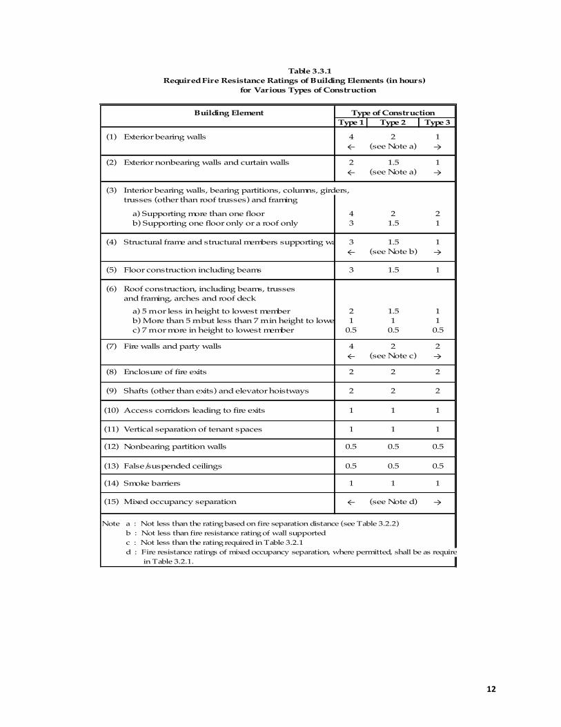
4.4 Fire resistance of structural members. The fire resistance of structural members shall be in compliance with BNBC Part 3 Chapter 3 and Table 3.3.1 (repeated below).
12
Table 3.3.1 Required Fire Resistance Ratings of Building Elements (in hours) for Various Types of Construction
Building Element Type of ConstructionType 1 Type 2 Type 3
(1) Exterior bearing walls 4 2 1← (see Note a) →
(2) Exterior nonbearing walls and curtain walls 2 1.5 1← (see Note a) →
(3) Interior bearing walls, bearing partitions, columns, girders,trusses (other than roof trusses) and framing
a) Supporting more than one floor 4 2 2 b) Supporting one floor only or a roof only 3 1.5 1
(4) Structural frame and structural members supporting wall 3 1.5 1← (see Note b) →
(5) Floor construction including beams 3 1.5 1
(6) Roof construction, including beams, trussesand framing, arches and roof deck
a) 5 m or less in height to lowest member 2 1.5 1 b) More than 5 m but less than 7 m in height to lowest member1 1 1 c) 7 m or more in height to lowest member 0.5 0.5 0.5
(7) Fire walls and party walls 4 2 2← (see Note c) →
(8) Enclosure of fire exits 2 2 2
(9) Shafts (other than exits) and elevator hoistways 2 2 2
(10) Access corridors leading to fire exits 1 1 1
(11) Vertical separation of tenant spaces 1 1 1
(12) Nonbearing partition walls 0.5 0.5 0.5
(13) False/suspended ceilings 0.5 0.5 0.5
(14) Smoke barriers 1 1 1
(15) Mixed occupancy separation ← (see Note d) →
Note : a : Not less than the rating based on fire separation distance (see Table 3.2.2) b : Not less than fire resistance rating of wall supported c : Not less than the rating required in Table 3.2.1 d : Fire resistance ratings of mixed occupancy separation, where permitted, shall be as required in Table 3.2.1.
13
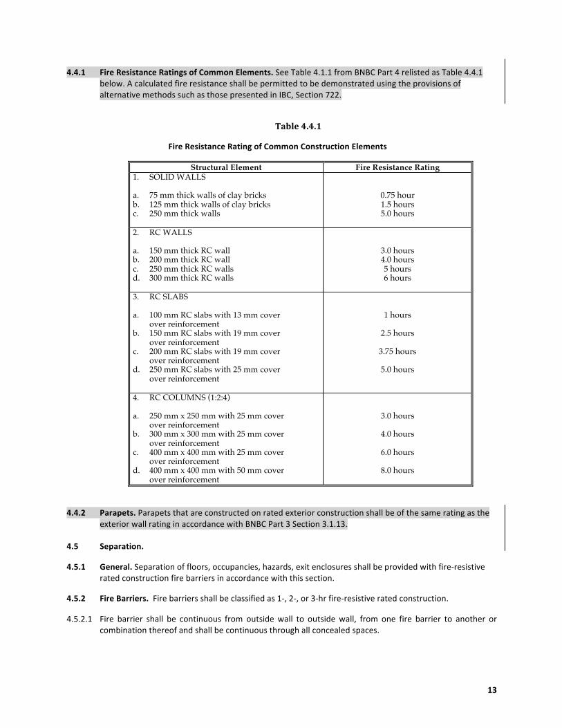
4.4.1 Fire Resistance Ratings of Common Elements. See Table 4.1.1 from BNBC Part 4 relisted as Table 4.4.1 below. A calculated fire resistance shall be permitted to be demonstrated using the provisions of alternative methods such as those presented in IBC, Section 722.
Table 4.4.1
Fire Resistance Rating of Common Construction Elements
Structural Element Fire Resistance Rating 1. SOLID WALLS a. 75 mm thick walls of clay bricks b. 125 mm thick walls of clay bricks c. 250 mm thick walls
0.75 hour 1.5 hours 5.0 hours
2. RC WALLS a. 150 mm thick RC wall b. 200 mm thick RC wall c. 250 mm thick RC walls d. 300 mm thick RC walls
3.0 hours 4.0 hours 5 hours 6 hours
3. RC SLABS a. 100 mm RC slabs with 13 mm cover over reinforcement b. 150 mm RC slabs with 19 mm cover over reinforcement c. 200 mm RC slabs with 19 mm cover over reinforcement d. 250 mm RC slabs with 25 mm cover over reinforcement
1 hours
2.5 hours
3.75 hours
5.0 hours
4. RC COLUMNS (1:2:4) a. 250 mm x 250 mm with 25 mm cover over reinforcement b. 300 mm x 300 mm with 25 mm cover over reinforcement c. 400 mm x 400 mm with 25 mm cover over reinforcement d. 400 mm x 400 mm with 50 mm cover over reinforcement
3.0 hours
4.0 hours
6.0 hours
8.0 hours
4.4.2 Parapets. Parapets that are constructed on rated exterior construction shall be of the same rating as the exterior wall rating in accordance with BNBC Part 3 Section 3.1.13.
4.5 Separation.
4.5.1 General. Separation of floors, occupancies, hazards, exit enclosures shall be provided with fire-‐resistive rated construction fire barriers in accordance with this section.
4.5.2 Fire Barriers. Fire barriers shall be classified as 1-‐, 2-‐, or 3-‐hr fire-‐resistive rated construction.
4.5.2.1 Fire barrier shall be continuous from outside wall to outside wall, from one fire barrier to another or combination thereof and shall be continuous through all concealed spaces.
14
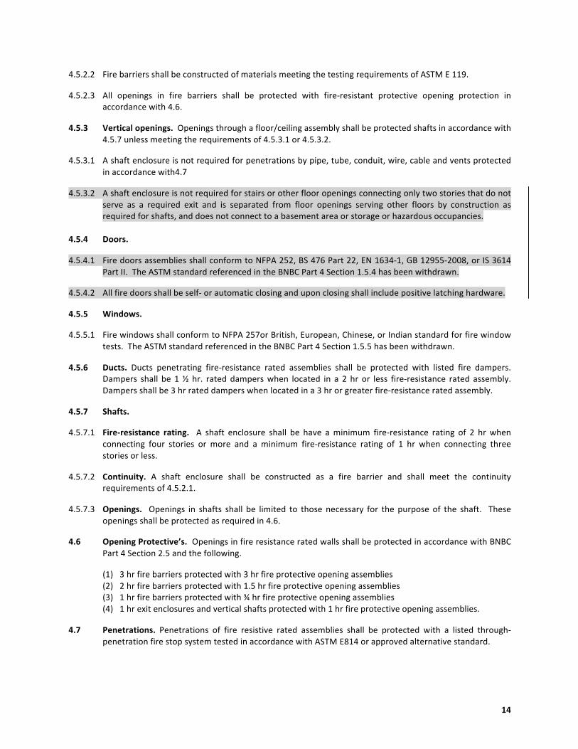
4.5.2.2 Fire barriers shall be constructed of materials meeting the testing requirements of ASTM E 119.
4.5.2.3 All openings in fire barriers shall be protected with fire-‐resistant protective opening protection in accordance with 4.6.
4.5.3 Vertical openings. Openings through a floor/ceiling assembly shall be protected shafts in accordance with 4.5.7 unless meeting the requirements of 4.5.3.1 or 4.5.3.2.
4.5.3.1 A shaft enclosure is not required for penetrations by pipe, tube, conduit, wire, cable and vents protected in accordance with4.7
4.5.3.2 A shaft enclosure is not required for stairs or other floor openings connecting only two stories that do not serve as a required exit and is separated from floor openings serving other floors by construction as required for shafts, and does not connect to a basement area or storage or hazardous occupancies.
4.5.4 Doors.
4.5.4.1 Fire doors assemblies shall conform to NFPA 252, BS 476 Part 22, EN 1634-‐1, GB 12955-‐2008, or IS 3614 Part II. The ASTM standard referenced in the BNBC Part 4 Section 1.5.4 has been withdrawn.
4.5.4.2 All fire doors shall be self-‐ or automatic closing and upon closing shall include positive latching hardware.
4.5.5 Windows.
4.5.5.1 Fire windows shall conform to NFPA 257or British, European, Chinese, or Indian standard for fire window tests. The ASTM standard referenced in the BNBC Part 4 Section 1.5.5 has been withdrawn.
4.5.6 Ducts. Ducts penetrating fire-‐resistance rated assemblies shall be protected with listed fire dampers. Dampers shall be 1 ½ hr. rated dampers when located in a 2 hr or less fire-‐resistance rated assembly. Dampers shall be 3 hr rated dampers when located in a 3 hr or greater fire-‐resistance rated assembly.
4.5.7 Shafts.
4.5.7.1 Fire-‐resistance rating. A shaft enclosure shall be have a minimum fire-‐resistance rating of 2 hr when connecting four stories or more and a minimum fire-‐resistance rating of 1 hr when connecting three stories or less.
4.5.7.2 Continuity. A shaft enclosure shall be constructed as a fire barrier and shall meet the continuity requirements of 4.5.2.1.
4.5.7.3 Openings. Openings in shafts shall be limited to those necessary for the purpose of the shaft. These openings shall be protected as required in 4.6.
4.6 Opening Protective’s. Openings in fire resistance rated walls shall be protected in accordance with BNBC Part 4 Section 2.5 and the following.
(1) 3 hr fire barriers protected with 3 hr fire protective opening assemblies (2) 2 hr fire barriers protected with 1.5 hr fire protective opening assemblies (3) 1 hr fire barriers protected with ¾ hr fire protective opening assemblies (4) 1 hr exit enclosures and vertical shafts protected with 1 hr fire protective opening assemblies.
4.7 Penetrations. Penetrations of fire resistive rated assemblies shall be protected with a listed through-‐penetration fire stop system tested in accordance with ASTM E814 or approved alternative standard.

15
4.7.1 Penetrations in a concrete or masonry wall by steel, ferrous or copper conduits, pipes, tubes or vents with a maximum 150 mm (6 in.) nominal diameter where the area of the opening through the wall does not exceed 0.0929 m2 (144 in2) shall be permitted to be protected using concrete, grout or mortar installed the full thickness of the wall to maintain the fire-‐resistance rating.
4.7.2 Penetrations in a single concrete floor by steel, ferrous or copper conduits, pipes, tubes or vents with a
maximum 150 mm (6 in.) nominal diameter shall be permitted to be protected using concrete, grout or mortar installed the full thickness of the floor or the thickness required to maintain the fire-‐resistance rating. The penetrating items shall not be limited to the penetration of a single concrete floor, provided the area of the opening through each floor does not exceed 0.0929 m2 (144 in2).
Part 5 Fire Protection Systems
16
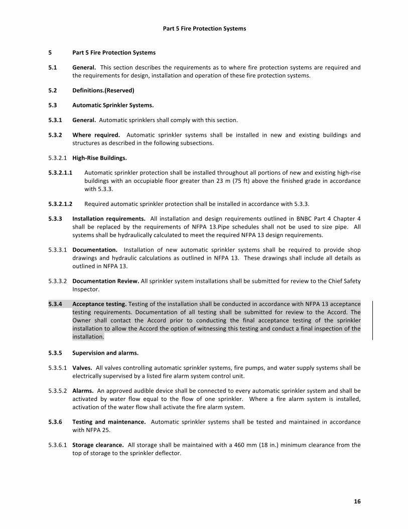
5 Part 5 Fire Protection Systems
5.1 General. This section describes the requirements as to where fire protection systems are required and the requirements for design, installation and operation of these fire protection systems.
5.2 Definitions.(Reserved)
5.3 Automatic Sprinkler Systems.
5.3.1 General. Automatic sprinklers shall comply with this section.
5.3.2 Where required. Automatic sprinkler systems shall be installed in new and existing buildings and structures as described in the following subsections.
5.3.2.1 High-‐Rise Buildings.
5.3.2.1.1 Automatic sprinkler protection shall be installed throughout all portions of new and existing high-‐rise buildings with an occupiable floor greater than 23 m (75 ft) above the finished grade in accordance with 5.3.3.
5.3.2.1.2 Required automatic sprinkler protection shall be installed in accordance with 5.3.3.
5.3.3 Installation requirements. All installation and design requirements outlined in BNBC Part 4 Chapter 4 shall be replaced by the requirements of NFPA 13.Pipe schedules shall not be used to size pipe. All systems shall be hydraulically calculated to meet the required NFPA 13 design requirements.
5.3.3.1 Documentation. Installation of new automatic sprinkler systems shall be required to provide shop drawings and hydraulic calculations as outlined in NFPA 13. These drawings shall include all details as outlined in NFPA 13.
5.3.3.2 Documentation Review. All sprinkler system installations shall be submitted for review to the Chief Safety Inspector.
5.3.4 Acceptance testing. Testing of the installation shall be conducted in accordance with NFPA 13 acceptance testing requirements. Documentation of all testing shall be submitted for review to the Accord. The Owner shall contact the Accord prior to conducting the final acceptance testing of the sprinkler installation to allow the Accord the option of witnessing this testing and conduct a final inspection of the installation.
5.3.5 Supervision and alarms.
5.3.5.1 Valves. All valves controlling automatic sprinkler systems, fire pumps, and water supply systems shall be electrically supervised by a listed fire alarm system control unit.
5.3.5.2 Alarms. An approved audible device shall be connected to every automatic sprinkler system and shall be activated by water flow equal to the flow of one sprinkler. Where a fire alarm system is installed, activation of the water flow shall activate the fire alarm system.
5.3.6 Testing and maintenance. Automatic sprinkler systems shall be tested and maintained in accordance with NFPA 25.
5.3.6.1 Storage clearance. All storage shall be maintained with a 460 mm (18 in.) minimum clearance from the top of storage to the sprinkler deflector.

Part 5 Fire Protection Systems
17
5.3.6.2 Solid-‐shelves.
5.3.6.2.1 Racks. Unless in-‐rack automatic sprinklers have been designed and installed, solid shelf racking shall not be used. A minimum of 50% openings in shelving material shall be considered open shelves. See NFPA 13 for further clarification.
5.3.6.2.2 Shelves. Shelving units not greater than 760 mm (30 in.) deep can have solid shelves. Back to back solid shelf units not greater than 760 mm (30 in.) deep each with a solid vertical barrier can have solid shelves. See NFPA 13 for further clarification.
5.3.6.3 Aisles. Minimum aisles shall be maintained free of storage in accordance with NFPA 13 based on the design criteria used for the sprinkler system.
5.4 Standpipe Systems.
5.4.1 General. Standpipe fire protection systems shall comply with this section.
5.4.2 Where required. A Class III standpipe system (both a 40 mm connection with attached hose and a 65 mm connection) shall be installed throughout all new and existing buildings and structures where the highest occupied floor is more than 10 m (33 ft) above grade or more than 10 m (33 ft) below grade.
5.4.2.1 Where the building is protected throughout with automatic sprinklers a Class I standpipe (65 mm connections without attached hose) shall be permitted. The installation of Occupant Use (Class II 40 mm connections) shall not be required.
5.4.3 Installation requirements. All installation and design requirements outlined in BNBC Part 4 Chapter 4 for combined standpipe and automatic sprinkler systems shall be replaced by the requirements of NFPA 14 with a minimum pressure of 450 kPa (65 psi) at the hydraulically most remote hose connection. Standalone standpipe systems shall meet the BNBC requirements with a minimum 450 kPa (65 psi) pressure at the hydraulically most remote hose connection, or NFPA 14.
5.4.3.1 Documentation. Installation of new combined standpipe and sprinkler systems shall be required to provide shop drawings and hydraulic calculations as outlined in NFPA 14. These drawings shall include all details as outlined in NFPA 14.
5.4.3.2 Documentation Review. All stand pipe system installations shall be submitted for review to the Chief Safety Inspector for review prior to commencement of installation.
5.4.3.3 Acceptance testing. Testing of the installation shall be conducted in accordance with NFPA 14 acceptance testing requirements. Documentation of all testing shall be submitted for review by the Accord. The Owner shall contact the Accord prior to conducting the final acceptance testing of the standpipe installation to allow the Accord the option of witnessing this testing and conduct a final inspection of the installation.
5.4.4 Location of hose connections.
5.4.4.1 Standpipe hose connections shall be located in all required stairwells at each floor level including occupiable roofs.

Part 5 Fire Protection Systems
18
5.5 Water supply.
5.5.1 Installation requirements. All new installations and design requirements outlined in BNBC Part 4 Chapter 4 for water supplies shall be replaced by the requirements of NFPA 20 (fire pumps), NFPA 22 (water tanks), and NFPA 24 (underground water mains). Existing water supplies shall be evaluated for reliability and support the hydraulic demands and duration of any new or existing systems supplied.
5.5.1.1 Documentation. Installation of new fire protection water supply systems shall be required to provide shop drawings and hydraulic calculations as outlined in NFPA 13, 20, 22, and 24. These drawings shall include all details as outlined in NFPA 13, 20, 22, and 24.
5.5.1.2 Documentation Review. All fire protection water supply system installation design documents shall be submitted for review by the Chief Safety Inspector prior to commencement of installation.
5.5.1.3 Acceptance testing. Testing of the installation shall be conducted in accordance with NFPA 13, 20, 22 and 24 acceptance testing requirements. Documentation of all testing shall be submitted for review by the Accord. The Owner shall contact the Accord prior to conducting the final acceptance testing of the installation to allow the Accord the option of witnessing this testing and conduct a final inspection of the installation.
5.5.2 Roof-‐mounted tanks. No new roof-‐mounted tanks to supply water to new standpipe or sprinkler
protection installations shall be allowed without complying with the requirements of Part 8.
5.5.3 Size of tanks. Tanks shall be sized for the minimum duration for fire protection supply as outlined in 5.3.3.
5.5.4 Fire department connections. Fire department (Siamese) inlet connections shall be provided to allow fire department pumper equipment to supplement the fire protection systems. Fire department outlet connections shall be provided to allow fire department pumper vehicles to draw water from ground-‐level or underground water storage tanks. Connections shall match the Fire Service and Civil Defence hose thread standard.
5.5.5 Acceptance. Acceptance testing of the installation shall be in accordance with NFPA 20, 22, and 24 testing requirements. Documentation of all testing shall be submitted to the Accord for review prior to final acceptance by the Accord. The Owner shall contact the Accord prior to conducting the final acceptance testing of the fire pump installation to allow the Accord the option to witness this test and to conduct a final inspection of the installation.
5.6 Portable Fire Extinguishers. Portable fire extinguishers shall be installed throughout all new and existing facilities in accordance with BNBC Part 4 Section 4.10 and NFPA 10.
5.6.1 Spacing. Extinguishers shall be placed so that maximum travel distance to the nearest unit shall not exceed 30 m (100 ft).
5.6.2 Mounting height.
5.6.2.1 Fire extinguishers having a gross weight not exceeding 18.14 kg (40 lb) shall be installed so that the top of the fire extinguisher is not more than 1.53 m (5 ft) above the floor (NFPA 10 6.1.3.8).
5.6.2.2 Fire extinguishers having a gross weight greater than 18.14 kg (40 lb) (except wheeled types) shall be installed so that the top of the fire extinguisher is not more than 1.07 m (3½ ft) above the floor (NFPA 10 6.1.3.8).

Part 5 Fire Protection Systems
19
5.7 Fire Alarm and Detection.
5.7.1 General. Fire alarm and detection systems shall comply with this section.
5.7.2 Definitions.
5.7.2.1 Manual alarm. A fire alarm system that activates the system alarm(s) and occupant notification devices by manual initiation.
5.7.2.2 Automatic alarm. A fire alarm system that activates the system alarm(s) and occupant notification devices by automatic initiating devices (e.g. smoke detector, heat detector, sprinkler water flow).
5.7.3 Where required. Automatic or manual fire alarm and detection systems shall be installed throughout all new and existing buildings and structures where required in 5.7.3.1 through 5.7.3.9.
5.7.3.1 Where automatic detection is required in 5.7.3.2 through 5.7.3.7, initiating devices shall include either smoke or fire detection devices spaced in accordance with NFPA 72. When complete sprinkler protection is provided throughout a floor with water flow devices designed to initiate the alarm notification, smoke and fire detection devices can be eliminated throughout that floor.
5.7.3.2 Occupancy B. A manual fire alarm system shall be provided in all new and existing day care facilities that are located in other occupancies or in buildings greater than 2 stories. When located in buildings with other occupancies requiring an automatic fire alarm system, an automatic fire alarm system shall be provided.
5.7.3.3 Occupancy E. An automatic fire alarm system shall be provided throughout all new and existing assembly occupancies.
5.7.3.4 Occupancy F. A manual fire alarm system shall be provided throughout all new and existing 3 or more story buildings. When located in buildings with other occupancies requiring an automatic fire alarm system, an automatic fire alarm system shall be provided. An automatic fire alarm and detection system shall be provided throughout all new and existing high-‐rise buildings as outlined in Section 3.6.
5.7.3.5 Occupancy G1. A manual fire alarm system shall be installed throughout all new and existing low-‐hazard industrial occupancies. When located in buildings with other occupancies requiring an automatic fire alarm system, an automatic fire alarm system shall be provided.
5.7.3.6 Occupancy G2. An automatic fire alarm and detection system shall be provided throughout all new and existing moderate hazard industrial occupancies.
5.7.3.7 Occupancy H. A manual fire alarm system shall be provided throughout all new and existing storage occupancies. When located in buildings with other occupancies requiring an automatic fire alarm system, an automatic fire alarm system shall be provided.
5.7.3.8 Occupancy J. An automatic fire alarm and detection system shall be provided throughout all new and existing hazardous occupancies.
5.7.3.9 Occupancy K. A manual fire alarm system shall be provided throughout all miscellaneous occupancies. When located in buildings with other occupancies requiring an automatic fire alarm system, an automatic fire alarm system shall be provided.
5.7.4 Installation requirements. All installation and design requirements outlined in BNBC Part 4 Section 4.4 shall be supplemented by the requirements of NFPA 72.
Part 5 Fire Protection Systems
20
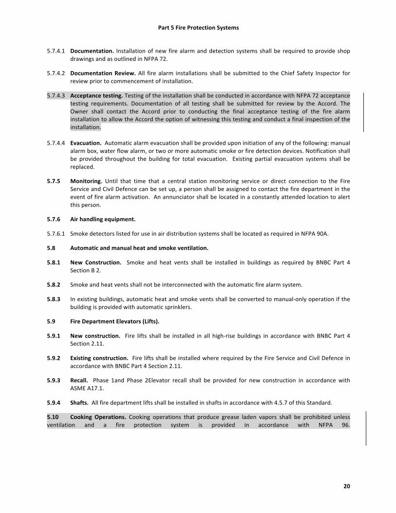
5.7.4.1 Documentation. Installation of new fire alarm and detection systems shall be required to provide shop drawings and as outlined in NFPA 72.
5.7.4.2 Documentation Review. All fire alarm installations shall be submitted to the Chief Safety Inspector for review prior to commencement of installation.
5.7.4.3 Acceptance testing. Testing of the installation shall be conducted in accordance with NFPA 72 acceptance testing requirements. Documentation of all testing shall be submitted for review by the Accord. The Owner shall contact the Accord prior to conducting the final acceptance testing of the fire alarm installation to allow the Accord the option of witnessing this testing and conduct a final inspection of the installation.
5.7.4.4 Evacuation. Automatic alarm evacuation shall be provided upon initiation of any of the following: manual alarm box, water flow alarm, or two or more automatic smoke or fire detection devices. Notification shall be provided throughout the building for total evacuation. Existing partial evacuation systems shall be replaced.
5.7.5 Monitoring. Until that time that a central station monitoring service or direct connection to the Fire Service and Civil Defence can be set up, a person shall be assigned to contact the fire department in the event of fire alarm activation. An annunciator shall be located in a constantly attended location to alert this person.
5.7.6 Air handling equipment.
5.7.6.1 Smoke detectors listed for use in air distribution systems shall be located as required in NFPA 90A.
5.8 Automatic and manual heat and smoke ventilation.
5.8.1 New Construction. Smoke and heat vents shall be installed in buildings as required by BNBC Part 4 Section B 2.
5.8.2 Smoke and heat vents shall not be interconnected with the automatic fire alarm system.
5.8.3 In existing buildings, automatic heat and smoke vents shall be converted to manual-‐only operation if the building is provided with automatic sprinklers.
5.9 Fire Department Elevators (Lifts).
5.9.1 New construction. Fire lifts shall be installed in all high-‐rise buildings in accordance with BNBC Part 4 Section 2.11.
5.9.2 Existing construction. Fire lifts shall be installed where required by the Fire Service and Civil Defence in accordance with BNBC Part 4 Section 2.11.
5.9.3 Recall. Phase 1and Phase 2Elevator recall shall be provided for new construction in accordance with ASME A17.1.
5.9.4 Shafts. All fire department lifts shall be installed in shafts in accordance with 4.5.7 of this Standard.
5.10 Cooking Operations. Cooking operations that produce grease laden vapors shall be prohibited unless ventilation and a fire protection system is provided in accordance with NFPA 96.

Part 6 Means of Egress
21
6 Part 6 Means of Egress
6.1 General. Buildings shall be provided with a means of egress system for all occupants to safely evacuate from buildings and structures.
6.2 Definitions. (Reserved)
6.3 General Means of Egress
6.3.1 Separation of Means of Egress.
6.3.1.1 Corridors. Exit access corridors serving an occupant load exceeding 30 shall be separated by walls having a fire resistance rating of 1 hr in accordance with 0 unless provided with automatic sprinkler protection throughout the story or building.
6.3.1.2 Exits. Exits shall be enclosed with fire-‐resistance rated construction as outlined in 6.3.1.2.1 through 6.3.1.2.3.
6.3.1.2.1 Exits connecting three or fewer stories shall be enclosed with a minimum 1-‐hr fire-‐resistance rating.
6.3.1.2.2 Exits connecting four or more stories shall be enclosed with a minimum 2-‐hr fire-‐resistance rating.
6.3.1.2.3 Exits shall be enclosed with the same fire-‐resistance rating as the floor penetrated but will not need to exceed 2 hr.
6.3.1.3 Exterior exit stairs. Exterior exit stairs shall be separated from the building with the rating requirements of 6.3.1.2. The rating of the exterior wall shall extend 3.05 m (10 ft) beyond the ends of the stair structure.
6.3.2 Interior Finish. All interior finishes for exits shall be limited to a flame spread index of 75 and smoke developed of 450 as tested in accordance with ASTM E 84.
6.3.3 Headroom. All means of egress shall have a minimum ceiling height of 2.3 m (7 ft 6 in.) with projections from the ceiling not less than 2.03 m (6 ft 8 in.). The minimum ceiling height shall be maintained for at least 2/3 of the space or room as long as the remaining area shall be not less than 2.03 m (6 ft 8 in.). Headroom on stairs shall not be less than 2.03 m (6 ft 8 in.).
6.3.4 Walking surfaces.
6.3.4.1 Changes in elevation. Abrupt changes in elevation of walking surfaces shall not exceed ¼ in. unless provided with a beveled slope of 1 in 2 that do not exceed ½ in. Changes greater than ½ in. shall meet the requirements for 6.3.5.
6.3.4.2 Walking surfaces shall be mostly level; however, shall not exceed a slope of 1 in 20 in the direction of travel unless meeting the requirements for ramps in 6.10.
6.3.5 Changes in Level. Changes in level exceeding 535 mm (21 in.) in elevation shall meet the requirements for stairs in 6.9or ramps in 6.10.
6.3.5.1 The change in level shall be readily apparent and if not, marked with additional signage or floor markings.
6.3.6 Slip Resistance. Walking surfaces, including stairway treads shall be uniformly slip resistant.

Part 6 Means of Egress
22
6.3.7 Guards. Guards shall be provided in accordance with 6.12 on the open sides of means of egress components where the elevation exceeds 760 mm (30 in.) above the ground or floor below.
6.3.8 Impediments to means of egress. No locks or other devices shall be installed on a means of egress component that would prevent any occupant from having safe egress from the building or structure.
6.3.9 Reliability. Means of egress shall be maintained continuously free and clear of all obstructions or impediments to full instant use in the case of fire or other emergency.
6.3.9.1 Furnishings, decorations. No furnishings, decorations, or other objects shall obstruct exits and access to exits. Nothing shall obstruct or impede visibility to exits.
6.4 Occupant Load
6.4.1 The occupant load, in number of persons for whom means of egress are required, shall be determined on the basis of the occupant load factors in BNBC Part 4 Section 3.5.1 that are characteristic for the use of the space or the maximum probable population of the space, whichever is greater.
6.4.2 The occupant load factors from the BNBC are as follows:
(1) Assembly with tables and chairs: 1.5 m2 per occupant (16 ft2 per occupant) net (2) Assembly without fixed seats: 0.7m2 per occupant (7 ft2 per occupant) net (3) Offices: 10 m2 per occupant (100 ft2 per occupant) gross (4) Industrial: 10 m2 per occupant (100 ft2 per occupant) gross (5) Storage: 30 m2 per occupant (300 ft2 per occupant) gross (6) Hazardous: 10 m2 per occupant (100 ft2 per occupant) gross
6.4.2.1 RMG factories shall have a calculated occupant load of 2.3 m2per occupant (25 ft2 per occupant). This occupant load factor is permitted to be increased or decreased based on the actual number of occupants.
6.4.3 Increased occupant load. The occupant load is permitted to be increased above the calculated occupant load provided that all other means of egress requirements for that higher occupant load are met.
6.4.4 Posting of occupant load. The occupant load shall be posted for every assembly and production floor in a facility in a conspicuous space near the main exit or exit access doorway for the space.
6.5 Egress Width
6.5.1 Minimum width of aisles. Aisles shall be provided with a minimum unobstructed clear-‐width of 0.9 m (36 in.).
6.5.2 Means of egress continuity. The path of egress travel along a means of egress shall not be interrupted by any obstruction. The capacity of the means of egress shall not be reduced along the path of travel.
6.5.3 Capacity. The total capacity of the means of egress for any story, floor, or other occupied space shall be sufficient for the occupant load as calculated in 6.4.1.
6.5.4 Capacity Factors. The capacity factors for calculating the available egress for each means of egress component shall be in accordance with BNBC Part 4 Table 4.3.2 (repeated below).
6.5.4.1 For assembly use areas provided for prayer halls, dining halls and like areas as well as business areas that are for integral use by the factory workers, the capacity factor for the primary occupancy use of the building shall be permitted to be used.

Part 6 Means of Egress
23
BNBC Table 4.3.2 Required Exit Width per Occupant
Occupancy
Buildings without Sprinkler System (mm per person)
Buildings thoroughly Sprinkled (mm per person)
Stairways Ramps & Corridors
Doors Stairways Ramps & Corridors
Doors
A Residential B Educational F1,F2, Business & F4 Mercantile G Industrial H Storage
8
5
4
5
4
4
C1,C2, Institutional C3
10 5 4 5 5 4
C4 Institutional 8 5 4 8 5 4
D Health Care 25 18 10 15 12 10
E Assembly F3 Business and Mercantile
10
7
5
7
5
5
J Hazardous 8 5 4 8 5 4
6.5.5 Sufficient Capacity. For new construction, where more than one means of egress is required, the means of egress shall be of such width and capacity that the loss of any one means of egress leaves available not less than 50 percent of the required capacity.
6.5.6 Minimum widths.
6.5.6.1 Doors.
6.5.6.1.1 Doors in an existing means of egress shall have a minimum width of 0.8 m (32 in.).
6.5.6.1.2 New doors in a means of egress shall have a minimum width of 1 m (39 in.).
6.5.6.2 Stairs.
6.5.6.2.1 In new construction and for newly constructed stairs, stairs shall have a minimum width of 1.5 m (60 in.) for all industrial occupancies and 2.0 m (79 in.) for all assembly occupancies. For assembly use areas provided for prayer halls, dining halls and like areas that are for integral use by the factory workers, the minimum width for the primary occupancy use of the building shall be permitted to be used.
6.5.6.2.1 In new construction and for newly constructed stairs, stairs shall have a minimum width of 1.5 m (60
in.) for all industrial occupancies and 2.0 m (79 in.) for all assembly occupancies. For assembly use areas provided for prayer halls, dining halls and like areas that are for integral use by the factory workers, the minimum width for the primary occupancy use of the building shall be permitted to be used.
6.5.6.2.2 In existing construction, stairs shall have a minimum width of 0.9 m (35 in.).

Part 6 Means of Egress
24
6.6 Number of Means of Egress
6.6.1 General. The number of means of egress from any floor, story or portion thereof shall not be less than 2 except where a single exit is permitted by 6.6.2, a single means of egress is permitted by 6.6.5 or where a greater number is required by 6.6.3.
6.6.2 Single exits. Only one exit shall be required in existing buildings where the occupant load and travel
distance listed in Table 6.6.2are not exceeded.
TABLE 6.6.2 STORIES WITH ONE EXIT Story Occupancy Maximum Occupants per Floor and Travel Distance Ground or Basement
B 50occupants and 23 m (75 ft) travel distance E, F, G, K 50 occupants and 23 m (75 ft) travel distance
H 30 occupants and 30 m (100 ft) travel distance J 5 occupants and 8 m (25 ft) travel distance
Second story F, G 30 occupants and 23 m (75 ft) travel distance H 30 occupants and 23 m (75 ft) travel distance
6.6.3 High occupant load. The number of means of egress from any floor or story shall not be less than 3 when the occupant load exceeds 500 per story and not less than 4 when the occupant load exceeds 1000 per story.
6.6.4 Occupied roofs. Occupied roofs shall be provided with the minimum number of exits required as a story.
6.6.5 Spaces with One Means of Egress. A single means of egress shall be permitted for spaces having an occupant load of not more than 49 and where the common path of egress travel does not exceed the limitations of 6.13.2.
6.6.6 Arrangement of Exits. Where two or more exits or means of egress are required, the exit doors or means of egress openings shall be located a distance apart equal to not less than one-‐half of the length of the maximum overall diagonal dimension of the building or area to be served measured in a straight line between exits or egress openings. Where the building is provided with a complete automatic sprinkler system, the separation of the exits or means of egress openings shall be not less than one-‐third of the maximum overall diagonal dimension.
6.7 Egress Illumination. All paths of egress shall be provided with illumination in accordance with Part 10 of this Standard.
6.8 Doors and Gates
6.8.1 Door swing. All doors in a means of egress shall be of the side-‐hinged swinging type. Roll-‐down and sliding gates and shutters shall not be allowed. Doors serving an occupant load of more than 50 shall swing in the direction of egress travel.

Part 6 Means of Egress
25
6.8.2 Locking.
6.8.2.1 General. Doors shall not be locked in the direction of egress under any conditions. All existing hasps, locks, slide bolts, and other locking devices shall be removed unless provided for in 6.8.2.2 and 6.8.2.3.
6.8.2.2 Doors may be locked where the latch and lock are disengaged with one motion where the occupant load does not exceed 49 persons. Turning a door handle and disengaging a lock is considered two motions.
6.8.2.3 Doors may be provided with locking hardware from the ingress side provided that a panic bar is installed on any door with an occupant load exceeding 49 persons. The re-‐entry provisions of6.8.3 must be met.
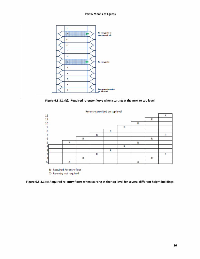
6.8.3 Re-‐entry. Every door in a stair enclosure serving more than 5 stories shall be provided with re-‐entry unless it meets the requirements of 6.8.3.1.
6.8.3.1 Stair doors may be permitted to be locked from the stair (ingress) side that prevents re-‐entry to the floor provided that re-‐entry to access another exit is provided such that, there are not more than 4 stories intervening between re-‐entry floors, re-‐entry is allowed on the top or next to top level, re-‐entry doors are identified as such on the stair side, and locked doors shall be identified as to the nearest re-‐entry floors. When the discharge floor (typically the ground floor) is determined to be a required re-‐entry floor using the above requirements, re-‐entry does not have to be provided back into the building on this level. See examples below.
Figure 6.8.3.1 (a).Required re-‐entry floors when starting at the top level.
Part 6 Means of Egress
26
Figure 6.8.3.1 (b). Required re-‐entry floors when starting at the next to top level.
Figure 6.8.3.1 (c).Required re-‐entry floors when starting at the top level for several different height buildings.

Part 6 Means of Egress
27
Figure 6.8.3.1 (d). Required re-‐entry floors when starting at the next to top level for several different height buildings.
6.8.4 Warehouse. Doors to storage buildings shall be in compliance with BNBC Part 4 Section 3.24.2.
6.8.5 Landings. A landing shall be provided on both sides of doors used in the means of egress. Door shall not swing out over stairs.
6.9 Stairs.
6.9.1 New Construction. Newly constructed stairs shall be in compliance with BNBC Part 3 Section 1.12.5.
6.9.2 Existing. Existing stairs shall meet the requirements of this subsection.
6.9.2.1 Stairs shall be of noncombustible construction.
6.9.2.2 Landings. Landings with same width as the stair clear width shall be provided at each level and at intermediate landings. Existing landings that are less than the stair width, shall reduce the overall available capacity of the stair as calculated in 6.5.
6.9.2.3 Treads. Stair treads shall be of nominal uniformity.
6.9.2.3.1 The maximum riser height for any stair shall be 215 mm (8.5 in.).
6.9.2.3.2 Any riser height at the top or bottom step in a stair runexceeding more than 51 mm (2 in.)difference from the adjacent riser height shall be modified to be within this tolerance.
6.9.2.3.3 Any riser height or tread depth not at the top or bottom step in a stair run exceeding more than 25 mm (1 in.) difference from the adjacent step shall be modified to be within this tolerance.
6.9.2.3.4 For existing stairs that do not meet these tread dimensions and will require extensive rework of the stairway, a full detailed analysis of the tread dimensions can be submitted to the Chief Safety Inspector for review and approval of an alternate corrective action plan.

Part 6 Means of Egress
28
6.9.2.4 Handrails. Handrails shall be provided on both sides of each stairway. Intermediate handrails shall be provided when the stair width exceeds 2.2 m (87 in.).
6.9.2.5 Guards. Guards shall be provided in stairs in accordance with 6.12.2.
6.9.3 Signs.
6.9.3.1 Stair designation signs shall be provided at each floor entrance from the stair to the floor in English and Bengali. Signs shall indicate the name of the stair and the floor level. Signs shall be posted adjacent to the door.
6.10 Ramps.
6.10.1 Width. Ramps used in a means of egress shall not reduce the overall means of egress width. The minimum width shall be 1.1 m (44 in.).
6.10.2 Slope. New ramps shall not have a running slope greater than 1 in 12 (8 percent). Existing ramps shall not have a running slope greater than 1 in 8 (12.5 percent).
6.10.3 Handrails. Ramps shall be provided with handrails on both sides of the ramp.
6.11 Exit Signs.
6.11.1 Location. Lighted exit signs shall be placed at entrance to an exit. Additional exit signs shall be placed throughout the facility anywhere the continuation of the egress is not obvious.
6.11.2 Power. Lighted exit signs shall be provided with either battery backup or emergency power and shall be continuously illuminated.
6.11.3 Directional signs : Directional signs shall be provided where there is a change in the direction for the path of travel and the direction to an exit is not obvious.
6.12 Handrails and Guards.
6.12.1 Handrails.
6.12.1.1 New handrails shall have a minimum height of 865 mm (34 in.) and a maximum height of 965 mm (38 in.) as measured from the leading edge of the tread.
6.12.1.2 Existing handrails that are less than 760 mm (30 in.) or greater than 1100 mm (44 in.) as measured from the leading edge of the tread, shall be replaced with handrails meeting the requirements of 6.12.1.1.
6.12.2 Guards. Guards shall be provided at all open sides of means of egress that exceed 760 mm (30 in.) above the floor or finished ground below.
6.12.2.1 New guards shall have a minimum height of 1067 mm (42 in.).
6.12.2.2 Existing guards shall have a minimum height of 760 mm (30 in.).
6.12.2.3 Open guards shall have intermediate rails or pattern such that a sphere 200 mm (8 in.) in diameter cannot pass through any opening up to a height of 865 mm (34 in.).
6.12.2.4 Roofs. All occupiable roofs shall be provided with parapets or guards with a minimum height of 1067mm (42 in.).

Part 6 Means of Egress
29
6.13 Travel Distance.
6.13.1 General. Travel distance to reach an exit for new and existing shall not exceed the values listed in BNBC Part 4 Section 3.15.1 unless the requirements of 6.13.1.1 or 6.13.1.2 can be met.
6.13.1.1 Travel distance limitations for G2 (RMG factories) shall be increased to 60 m (200 ft) where a complete automatic fire detection system, portable fire extinguishers, and standpipe system are provided in accordance with this Standard.
6.13.1.2 Travel distance limitations for G2 (RMG factories) shall be increased to 122 m (400 ft) where a complete automatic sprinkler system, automatic fire alarm system, and portable fire extinguishers are provided in accordance with this Standard.
6.13.2 Common Path of Travel. The common path of egress travel shall not exceed 23 m (75 ft). Where the building is provided with a complete automatic sprinkler system, the common path of egress travel shall not exceed 30 m (100 ft). The common path of egress travel for Group H (storage) occupancies with not more than 30 occupants shall not exceed 30 m (100 ft). The common path of egress travel for Group J (high hazard) occupancies shall not exceed 8 m (25 ft).
6.13.3 Dead End Corridor. Dead end corridors shall not exceed that provided in Table 6.13.3
Table 6.13.3 Dead End Corridor Maximum Length
Occupancy Unsprinklered Sprinklered B, F, K 20 ft. 50 ft. E 20 ft. 20 ft. G 50 ft. 50 ft. H 50 ft. 100 ft. J Not Allowed
6.14 Exit Enclosures.
6.14.1 Ratings. Interior exit stairways and ramps shall be enclosed with fire barriers constructed in accordance with 4.5.2.
6.14.2 Termination. Interior exit stairways and ramps shall terminate at an exit discharge except where terminating at an exit passageway constructed in accordance with 6.15.
6.14.3 Openings. Openings into an exit enclosure other than unprotected exterior walls shall be limited to those necessary for exit access to the enclosure. In new construction, elevators shall not open into an exit enclosure. Openings from exit enclosures to storage areas, basements, transformer rooms, generator rooms, boiler rooms, and similar normally unoccupied spaces shall be provided with vestibules.
6.14.4 Penetrations. Penetrations into and through an exit enclosure shall be prohibited with the exception of required exit doors, sprinkler piping, standpipes, electrical raceway for fire alarm equipment, and electrical conduit serving the exit enclosure.
6.14.5 Exterior walls. Exterior walls of exit enclosures shall comply with 3.8.2.3.
6.14.6 Smoke proof enclosures. Smoke proof enclosures shall be provided for new stairs as required in BNBC Part 4 Section 3.13.

Part 6 Means of Egress
30
6.14.7 Exposures. Where nonrated walls or unprotected openings enclose the exterior of the stairway and the walls or openings are exposed by other parts of the building at an angle of less than 180degrees (3.14 rad), the building exterior walls within 3050mm (10 ft) horizontally of a nonrated wall or unprotected opening shall have a fire-‐resistance rating of not less than 1 hr. Openings within such exterior walls shall be protected by opening protectives having a fire protection rating of not less than ¾ hr. This construction shall extend vertically from the ground to a point 3050 mm (10 ft) above the topmost landing of the stairway or to the roof line, whichever is lower. [IBC 1022.7]
6.15 Exit Passageways.
6.15.1 Definition. An exit passageway is an exit component that is separated from other interior spaces of a building or structure by fire resistance-‐rated construction and opening protectives, and provides for a protected path of egress in a horizontal direction to the exit discharge or the public way.
6.15.2 General. Exit passageways shall be considered an extension of the stairs and shall not be used for any other purpose.
6.15.3 Construction. Exit passageways shall have walls, ceilings, and floors that meet the same rating requirement as the exit that is being served and shall not be less than 1 hr fire-‐resistance rated construction.
6.15.4 Termination. Exit passageways shall terminate at an exit discharge.
6.16 Horizontal Exits. Horizontal exits shall comply with the requirements of BNBC Part 4 Section 3.12.
6.17 Exit Discharge
6.17.1 General. Exits shall discharge directly to the exterior of the building unless meeting the requirements of 6.17.3 or 6.17.3. The exit discharge shall be at grade or provide direct access to grade. Exit discharge shall not reenter a building.
6.17.2 Egress Court. An egress court serving as a portion of the exit discharge shall be open to the sky or provided with a fire resistance rated enclosure the same as the exit enclosure. Egress courts less than 3050 mm (10 ft) in width (as measured from the building and the adjacent property line) shall be provided with walls having a 1-‐hr fire resistance rated construction for a distance of 3050 mm (10 ft) above the floor of the court.
6.17.3 Interior building exit discharge. A maximum of 50 percent of the number and capacity of the exit enclosures can discharge through areas on the level of exit discharge where all of the following are met:
(1) Automatic sprinkler protection is provided throughout the level of exit discharge or portion of the level of discharge where separated from non sprinklered portions of the floor by fire barriers with the same fire resistance rating as the exit enclosure.
(2) The interior discharge is not through a storage or hazardous occupancy. (3) The entire area of the level of exit discharge is separated from areas below by construction having a
fire resistance rating not less than that required for the exit enclosure. (4) The way to the exterior shall be free and unobstructed and shall be readily visible and identifiable
from the point of discharge of the interior exit.

Part 7 Building Materials
31
7 Part 7 Building Materials
7.1 The requirements of Part 5 of the 2006 BNBC are adopted in their entirety, with the following additional paragraphs.
7.2 Masonry-‐chip aggregate concrete (MCAC)
7.2.1 Masonry-‐chip aggregate concrete is allowed in existing factories with the following additional requirements.
7.2.2 If the structural building assessment or other indication suggests that that the factory includes structural use of MCAC, then special confirmation of adequacy will be required, including the following:
7.2.2.1 The compressive strength of columns, floor framing and shear walls using MCAC shall be investigated by an appropriate program of in-‐situ testing and representative destructive testing of core samples.
7.2.2.1.1 Alternatively, if the structure and its main load bearing elements do not show any sign of lack of performance and are found to have reasonable safety factor, as confirmed by simple calculations then the requirement of destructive testing of core samples to obtain in-‐situ strength may be waived.
7.2.2.2 If MCAC is used in any horizontal framing element exposed to rainfall or other source of water (such as roof level framing), then the top surface of the framing must be completely sealed from water intrusion by a well maintained protective coating.
7.2.2.2.1 Alternatively, if the structure has a positive drainage slope of at least 2% and drains with downspouts at low spots to prevent ponding, then the requirement for complete sealing of the top surface may be waived.
7.2.2.3 If columns or other structural elements using masonry-‐chip aggregate concrete are exposed to weather, they must be protected from exposure to water and dampness.
7.2.2.4 The structural design shall consider the effects of MCAC on reduction in elastic modulus of concrete, coefficient of creep and compressive strength compared to concrete with stone aggregates.
7.2.3 For new construction, the use of MCAC shall not be allowed in the following members:
1) Foundation, grade beams and columns below grade and in contact with water or ground.
2) Structural member in contact with ground or water or exposed to rainfall.
3) Any part of RCC frame structure in a high-‐rise construction (more than 20m or 65 ft).
7.3 Minimum Construction Material Properties In evaluating the structural capacity of existing structural elements:
7.3.1 Actual measured or tested properties of materials may be used for elements tested in accordance with ASTM Standards.
7.3.2 Where testing has not been used to confirm actual properties and there is no sign of structural distress or deficiency in the subject member, the following minimum properties may generally be used, unless good engineering judgment indicates lesser properties should be assumed:
7.3.2.1 Reinforced concrete (stone chip)– 16.5MPa (2370 psi)

Part 7 Building Materials
32
7.3.2.2 Reinforced concrete (masonry chip)– 14.5MPa (2045psi)
7.3.2.3 Reinforcing steel installed prior to 2004: – 275MPa (40 ksi)
7.3.2.4 Reinforcing steel installed from 2004 to present: – 415MPa (60 ksi)
7.3.2.5 A36 Structural steel – 248 MPa (36 ksi) yield strength
7.4 Minimum assumed density of reinforced concrete – 23.6 kN/m3 (150 pcf)
Part 8 Structural Design
33
8 Part 8 Structural Design
8.1 Applicability of Building Code
8.1.1 New factories shall comply with the more stringent requirements of this Standard and the 2006 Bangladesh National Building Code plus code updates and jurisdictional circulars as they may be issued from time to time.
8.1.2 Existing factory buildings are those that are in current use in the Bangladesh RMG industry at the time of adoption of this Standard.
8.1.3 For any substantial expansion of an existing factory, the expanded portions and the entire newly-‐configured factory structure shall comply with the requirements of Part 6 of the 2006 Bangladesh National Building Code.
Interpretive Guideline: Regardless of when a factory was constructed, the structural impact of any expansion on the entire structure must be analytically evaluated and confirmed by a qualified structural engineer.
8.1.4 Additions to Existing Structures. When an existing building or structure is substantially extended or otherwise altered, all portions thereof affected by such cause shall be strengthened, if necessary, to comply with the safety and serviceability requirements provided in the BNBC.
8.1.4.1 This Standard utilizes the 2006 BNBC (modified as noted herein) as the applicable standard for new factory construction and for all expansions or modifications to existing factories. When and if a new Bangladesh National Building Code is issued by the applicable Code-‐developing body, it will be adopted as the applicable technical standard for new factories and all expansions or modifications to existing factories.
8.1.4.2 A substantial expansion will be interpreted to mean any new floor or roof levels or horizontal floor additions or similar new structure.
8.2 Structural Integrity of Existing Factory Buildings:
8.2.1 Every existing factory building must demonstrate a minimum degree of structural integrity as confirmed by credible original structural documentation and a Preliminary Structural Assessment performed by an Accord inspector.
Interpretive Guideline: The intent of Section 8.2 is that every existing factory must evidence a reasonable level of structural integrity regardless of when it was constructed and regardless of the availability of credible structural documentation. This Standard requires the analytical confirmation of structural capacity of key gravity and lateral load-‐bearing elements for the actual in situ conditions in the factory by a qualified structural engineer working on behalf of the Factory Owner. Taken in tandem with acceptable observed structural performance of the overall structure, the Preliminary Structural Assessment may be accepted as evidence of a reasonable level of structural integrity. For factory buildings with noted concerns or unacceptable findings from the Preliminary Structural Assessment, a higher level of structural investigation, analysis, and ongoing inspections may be required.
8.2.2 Existing factory buildings and components thereof shall be assessed to confirm design adequacy to support all loads, including dead loads as they may occur and live loads as they may be imposed on the factory during its lifetime, without exceeding the allowable stresses or design strengths under applicable factored loads and load combinations for the materials of construction in the structural members and connections in accordance with the provisions of BNBC, except as specifically modified in this Standard.

Part 8 Structural Design
34
8.2.2.1 Interpretive Guideline: Structures must have analytically-‐determined or empirically-‐determined structural capacity to support all the imposed loads including occupants, equipment, water tanks, and storage loads without overstressing structural elements. Where the magnitude of dead loads and live loads can be determined with a high level of assurance, the applicable load factors and load combinations may be reduced as indicated in this Standard, subject to in-‐factory confirmation of the actual loads. The structural capacity of key elements must be confirmed and documented in accordance with accepted engineering design processes by qualified structural engineers.
8.2.3 The ultimate strength design method for reinforced concrete elements and systems and the Load Factor design method for structural steel structures shall be the basis of assessment under this Standard. Structural integrity of existing factories may be confirmed by Preliminary Structural Assessment as described in Section 8.3.
8.2.4 Serviceability. Structural framing systems and components shall be designed with adequate stiffness to avoid excessive cracking, deterioration, or unsafe conditions due to deflections, vibration, or any other serviceability shortcomings.
8.2.4.1 Interpretive Guideline: Deflections (sagging), rotations (twisting), perceivable vibrations, or other noticeable movements of the structure shall require additional structural investigation as required by this Standard. This intent of this Standard is to focus on Life Safety concerns rather than serviceability.
8.3 Preliminary Structural Assessment to Confirm Structural Integrity of Existing Factory Buildings
Interpretive Guideline. It is recognized that many Bangladeshi factory buildings were built before or absent active enforcement of Building Code requirements. Many of these factories lack basic documentation that could provide evidence of physical design characteristics such as element dimensions, reinforcing and material strengths which could be used to readily confirm the structural safety of the factories. Recognizing that absence of structural documentation does not make a factory unsafe, this protocol provides a methodology for Factory Owners who lack appropriate documentation to provide other acceptable evidence of structural integrity.
8.3.1 This protocol is applicable for factories that, in the sole opinion of the Accord inspector, lack complete, original, accurate, and credible structural documentation as described in BNBC 2006 Part 6 Section 1.9.
8.3.2 The Preliminary Structural Assessment shall include the following activities:
8.3.2.1 Review of available documents, either original structural documents prepared in accordance with BNBC Section 1.9 or as-‐built documents prepared in accordance with Section 8.20 of this Standard.
8.3.2.2 Visual assessment of all structural elements for evidence of distress, cracking, or lack of performance.
8.3.2.3 Visual and analytical confirmation of floor loading in compliance with floor load plans.
8.3.2.4 Visual confirmation of performance of foundations, including absence of settlement cracking, excessive perimeter separations or settlement, or lack of floor levelness attributable to foundation settlements.
8.3.2.4.1 In assessing the load capacity adequacy of a pile foundation system under an existing factory that has performed for at least five years without indications of excessive settling, the factory of safety shall be at least 1.5.
8.3.2.5 Visual confirmation of clear and redundant load path for lateral loads, including diaphragms and vertical elements. Visual observations shall note any evidence of apparent cracking or other lack of performance of lateral systems under prior lateral loading.
Part 8 Structural Design
35
8.3.2.6 Simple structural calculations to assess the basic capacity of structural members, including:
8.3.2.6.1 Columns and wall elements at most critical tiers, including lowest tier. Vertical elements shall be reviewed for maximum load combinations of forces due to axial and bending.
8.3.2.6.1.1 Unless confirmed otherwise by scanning or other investigations, columns may be assumed to be reinforced with a maximum of 1% steel times the gross plan area of the column.
8.3.2.6.2 Vulnerable or critical structural elements identified by the inspector including transfer girders, hangers, cantilevers, columns with high slenderness ratio, flat plate floors, and footings with inadequate thickness.
8.3.3 The general purpose of the Preliminary Structural Assessment, and any follow-‐up detailed structural assessment is to answer the following seven questions in the affirmative: (1) Is the vertical load carrying system logical? (2) Is the lateral load-‐carrying system apparent and does it have redundancy? (3) Are key structural elements such as columns, slender columns, flat plates, and transfer structures
satisfactory? (4) Is building performance in respect to foundation settlement satisfactory? (5) Is the structure free from any visible structural distress (progressive cracking) in main load-‐carrying
members? (6) Is the structural strength and performance of any visible vertical or horizontal extensions acceptable? (7) Are credible structural documents available?
a. Either credible original structural document in accordance with BNBC Section 1.9 or as-‐built documents in accordance with Section 8.20 will generally suffice.
8.4 Results of Preliminary Structural Assessment of Existing Factory Buildings
8.4.1 If the inspector determines that the answers to the seven questions in Sections 8.3.3 are affirmative, the factory may be found to be acceptably structurally safe and compliant with this Standard without further structural investigations, at the discretion of the inspector.
8.4.2 If the inspector determines that the answer to one or more of the seven questions in Sections 8.3.3 are negative, the inspector may recommend and/or conduct more detailed structural assessment, investigations or analysis.
8.4.3 If a more detailed engineering assessment is not to be carried out, inspectors are encouraged to conduct in-‐situ testing of material strengths coupled with outline calculations.
8.5 Detailed Structural Assessment of Existing Factory Buildings
8.5.1 At the sole judgment of the inspector, the inspector may conduct and document detailed structural assessments of material strengths and locations using non-‐destructive methods (Schmidt Hammer, UPV, ferro-‐scanning, or similar) or destructive (localized coring or selective removal of materials.)
8.5.2 If the visual assessment or the Preliminary Structural Assessment indicates areas of structural concern, distressed structural members, or other lack of compliance with the requirements of this Standard, then more detailed structural investigation shall be required.
8.5.3 Detailed engineering assessment shall be performed on any structural member identified as distressed. The cause and extent of structural distress shall be identified by assessment. To accomplish this, the Factory Owner shall engage a qualified Structural Engineering Consultant (QSEC) that meets the
Part 8 Structural Design
36
qualifications established by the Accord to provide structural advisory services to prepare all required design confirmation and structural documentation.
8.5.4 If required, the QSEC shall prepare as-‐built structural documents as described in the Section 8.20.
8.5.5 If required, the QSEC shall prepare Factory Loading Plans as described in Section 8.10.
8.5.6 If required, the QSEC shall conduct and document detailed structural condition assessment in accordance with the requirements of ACI 437, ASTM 2018, or similar accepted engineering practice. The strength of concrete and amounts of reinforcement in columns shall be assessed by Schmidt Hammer test, UPV, and/or core test and ferro-‐scanning.
8.5.7 If required, the QSEC shall conduct additional detailed structural condition assessments and investigations to determine the adequacy of specific structural elements, distressed structural members, or other conditions identified by the Assessor.
8.5.7.1 In this case, the QSEC shall state assumptions regarding strength and properties of key construction materials. Unless confirmed otherwise by testing of in-‐situ conditions in accordance with applicable ASTM test procedures, the QSEC shall determine the material properties using Section 7.3.
8.5.7.2 Unless confirmed otherwise by scanning or other investigations, columns may be assumed to be reinforced with a maximum of 1% steel times the gross plan area of the column.
8.5.8 The installation of mobile phone antennae or similar dish structures or towers atop any existing factory shall be critically examined against wind induced forces as specified by the BNBC using normal load factors. If a detailed structural assessment of the capacity of the structure to support such a tower indicates that the factory is adversely affected, then the tower shall be removed.
8.6 Remediation of Deficient or Overloaded Structural Elements
8.6.1 If the Preliminary Structural Assessment or more detailed structural investigations determine that structural distress in a structural member is due to inadequate structural capacity under applied loads, the Factory Owner shall take appropriate steps to remediate the overload by implementing one of the following methods:
8.6.1.1 The applied loads may be reduced to acceptable levels if possible by removal and limitation of structure, equipment, utilities, or floor loading, or
8.6.1.2 Overloaded structural elements may be strengthened using properly designed, documented, and installed strengthening and retrofit.
8.6.2 All retrofits are subject to technical review by Chief Safety Inspector prior to implementation.
8.6.3 All installation of retrofit shall be accomplished by specialty firms experienced in the materials and techniques of structural retrofit. See Section 8.30.
8.7 Phased Construction. When a building or structure is planned or anticipated to undergo phased construction, structural members therein shall be investigated and designed for any additional stresses arising due to such effect.
8.7.1 Interpretive Guideline: Temporary or permanent loads due to construction phasing must be anticipated and analytically confirmed by a qualified structural engineer prior to any expansion.

Part 8 Structural Design
37
8.8 Restrictions on Loading. The Factory Owner shall ensure that the live load for which a floor or roof is or has been designed, will not be exceeded during its use.
8.9 Factory Load Manager: The Factory Owner shall ensure that at least one individual, the Factory Load Manager who is located onsite full time at the factory, is trained in the structural capacity and operational load characteristics of the specific factory. The Factory Load Manager shall be responsible to ensure that the factory operational loads do not at any time exceed the factory floor loading limits as described on the Floor Loading Plans.
8.10 Floor Loading Plans (Load Plans). In every factory building, Load Plans shall be prepared for each floor. These Load Plans shall document the actual maximum operational loading that is intended and/or allowable on each floor. Load Plans shall include the items described in Section 8.20.4.3. The Load Plan for each floor shall be permanently and conspicuously posted on that floor. Load Plans are subject to review and approval by Accord inspectors. Sample load plan is included in Figure 20.
8.11 Floor Load Markings In areas of factory buildings used for storage of work materials and work products, walls, columns, and floors shall be clearly marked to indicate the acceptable loading limits as described in the Load Plan for that floor.
8.11.1 For existing factories with properly prepared and posted Factory Loading Plans, the requirements of BNBC Part 6 Section 1.4.5 for posting of live loads are waived.
8.11.1.1 Interpretive Guideline: Accord inspections will confirm clear posting of floor live load plans and clear marking of storage areas. In recognition that load plans are not currently prepared or posted, initial Accord inspections will be focused on helping the Factory Owner develop appropriate load plans based on the actual demonstrated floor capacity and operational utilization. The responsibility to produce and post load plans lies with the Factory Owner.

Part 8 Structural Design
38
8.12 Load Factors and Load Combinations for Structural Analysis
8.12.1 In analyzing the structural adequacy of existing factories, the load factors and load combinations described in Table 8.1 may be used only if the dead and live loads are confirmed by measurement as stated in Section 8.13 and 8.14.
Table 8.1: Alternate Load Factors and Load Combinations
Reinforced Concrete Structures Structural Steel Structures 1.2D + 1.6L 1.2D + 1.6Lf + 0.5Lr
1.05D + 1.25L + 1.0W 1.2D + 1.3W + 0.5Lf + 0.5Lr 1.2D + 1.5E + 0.5Lf
D = Dead Load L = Live Load W = Wind Load from any direction E = Seismic Load from any direction Lr = Roof Live Load Lf = Floor Live Load
NOTE: This Standard considers day-‐to-‐day loading conditions for assessment of existing RMG factory buildings considering life safety against building collapse. In this consideration, only service level wind loadings are considered for reinforced concrete buildings. However, assessments should note any key seismic characteristics of buildings in the report including irregularities, soft stories, and the like. For steel structures the BNBC-‐specified load factors are applicable.
8.13 Confirmation of Actual Dead Loads
8.13.1 As a requirement to use the load factors and load combinations stated in Table 8.1, dead loads shall be confirmed by measurement as follows:
8.13.2 Slab thicknesses shall be measured at mid-‐span of representative slab spans on each floor.
8.13.3 Dimensions of representative sampling of beams shall be field measured.
8.13.4 Dimensions of representative sampling of columns shall be field measured.
8.13.5 Construction materials of walls shall be confirmed by representative exploration.
8.13.6 Fixed service equipment and other permanent machinery, such as generators, water tanks, production equipment, electrical feeders and other machinery, heating, ventilating and air-‐conditioning systems, lifts and escalators, plumbing stacks and risers etc. may be considered as dead load whenever such equipment is supported by structural members and weights are confirmed by manufacturer’s data sheets provided by Factory Owner for each piece of equipment.

Part 8 Structural Design
39
8.14 Confirmation of Actual Operational Live Loads
8.14.1 As a requirement to use the load factors and load combinations stated in Table 8.1, operational live loads shall be confirmed by measurement as follows:
8.14.2 For stored work materials, each type of material shall be weighed and measured.
8.14.3 For stored work products, each size of boxed or packaged material shall be weighed and measured.
8.14.4 For other types of live load, confirmation shall be accomplished in the most appropriate means in the judgment of the Assessor.
8.14.5 The live loads used for the structural design of floors, roof and the supporting members shall be the greatest applied loads arising from the intended use or occupancy of the building, or from the stacking of materials and the use of equipment and propping during construction, but shall not be less than the minimum design live loads set out by the provisions of this section. For the design of new structural members for forces including live loads, requirements of the relevant sections of Chapter 1 of the BNBC shall also be fulfilled.
8.15 Minimum Floor Design Loads
8.15.1 Minimum floor design live loads for the review of factory sewing floors shall be 2.0kN/m2 (42psf).
8.15.2 Where density of operations, storage of materials, or equipment weights require live load capacity in excess of 2.0kN/m2 (42psf), the Factory Owner shall engage a qualified structural engineer to analytically confirm that the structure achieves the needed load capacity.
8.15.2.1 If the approved design documents for the factory construction do not explicitly confirm that the required load capacity exists, then the floor load capacity in the affected areas shall be analytically confirmed and certified by a qualified structural engineer.
8.15.2.2 A certification letter with accompanying plans and calculations shall be prepared in accordance with BNBC 1.9 or Section 8.20 and made available at the factory site for review by third parties.
8.15.3 For floors with design live load capacity of less than 2.0kN/m2 (42psf) (such as residential floors converted to factory use) the floor live load capacity shall be clearly indicated on the Floor Load Plans required by Section 8.20.
8.15.4 For areas of factory floors with actual operational live loads in excess of 2.0 kN/SM, a certification letter with accompanying plans and calculations shall be prepared in accordance with BNBC 1.9 or Section 8.20 and shall be made available at the factory site for review by third parties.
8.16 Confirmation of Actual Construction Material Properties
8.16.1 Where practical, all preliminary and detailed structural assessments will preferably consider actual in-‐situ material strengths as measured by non-‐destructive and destructive testing in conformance with applicable ASTM testing protocols.
8.16.2 Where field conditions allow and are acceptable in the judgment of the inspector, presumed minimum material strengths and characteristics may be used as stated in Section 7.3.

Part 8 Structural Design
40
8.17 Design for Lateral Loads
8.17.1 Every building, structure or portions thereof shall be designed to resist lateral loads due to wind in compliance with the forces, Load Factors and Load Combinations as stated in BNBC 2006 Section 1.5.3.
8.17.2 When dead loads, live loads, and material properties are confirmed as described in Sections 8.13, 8.14, and 8.16, and there are no signs of distress due to loading, the alternative Load Factors and Load Combinations stated in Table 8.1 may be used.
8.17.3 A redundant structural system with clear load path to foundations to resist lateral loads is required in all existing factories. If such a load path does not exist, or if the factory has been vertically expanded, the lateral-‐resisting capacity of the factory shall be analytically confirmed and strengthened as required to resist lateral loads.
8.17.4 Any of the lateral loads prescribed in Chapter 2 of the 2006 BNBC, considered either alone or in combination with other forces, whichever produces the most critical effect, shall govern the design.
8.17.4.1 Confirmation of capacity of reinforced concrete structures and components thereof to resist the effects of earthquake forces is not considered by this Standard.
8.17.4.1.1 Interpretive Guideline: Because the focus of this Standard is factory safety under day-‐to-‐day loads, seismic loadings are not required by this Standard for reinforced concrete structures, though they are required by the BNBC and are consistent with good practice.
8.17.5 Importance Factor Importance factor for all factory buildings and ancillary buildings shall be 1.0, unless hazardous materials are stored in the building. In that case, the importance factor shall be 1.5.
8.18 Seismic Bracing of Key Non-‐Structural Elements
8.18.1 The following non-‐structural elements suspended from, attached to, or resting atop the structure shall be adequately anchored and braced to resist earthquake forces:
8.18.1.1 Steam pipes
8.18.1.2 Gas pipes
8.18.1.3 Chemical or process pipes
8.18.1.4 Storage racks
8.18.1.5 Water tanks
8.18.1.6 Other suspended equipment weighing more than 1.8 kN that in the opinion of the inspector presents a danger to workers in an earthquake.
8.18.2 Seismic bracing for non-‐structural elements shall be designed using the requirements of BNBC 2.5.8.1.
8.18.2.1 Interpretive Guideline: This requirement applies to both new and existing factories. It is intended to ensure that falling non-‐structural elements in a seismic event do not create life safety hazards or hindrances to building egress.
8.19 Required Structural Documentation for New and Existing Factories
8.19.1 Every factory requires structural documentation that accurately describes the factory structure.

Part 8 Structural Design
41
8.19.2 Structural documentation shall be maintained at the factory site and made available to third parties assessing the structural safety of the factory.
8.19.3 All structural documentation shall be prepared and signed by the structural engineer responsible for the preparation of the documents.
8.19.4 New factories and any additions or expansions shall have complete structural documentation including Design Report and Structural Documents as described in BNBC Section 1.9.
8.19.5 Existing factories shall have one of the following types of documentation:
8.19.5.1 Complete and credible structural documentation prepared in general accordance with BNBC Section 1.9 and used as a basis for the original construction of the factory building, or
8.19.5.2 As-‐built structural documents that accurately describe the structural elements as described in Section 8.20.
8.19.5.3 Interpretive Guideline: It is recognized that few factories have complete structural documentation. It is not intended that the Factory Owner produce complete structural documents after construction is complete. In this case, as-‐built documents will be required from field investigations as outlined in Section 8.20.
8.20 Requirements for As-‐Built Documents
8.20.1 For existing factories that lack complete and credible documentation, credible as-‐built documentation shall suffice. As-‐built documents shall be prepared in accordance with this Section.
8.20.2 The Factory Owner shall engage a qualified structural engineer (QSEC) to prepare accurate as-‐built documents from firsthand knowledge and personal investigation of the actual in situ factory construction and operational conditions.
8.20.3 The credibility of structural documentation shall be determined by the Chief Safety Inspector on the basis of observations and tests at the factory.
8.20.4 As-‐built documents shall serve as the basis for any detailed structural analysis performed to confirm the capacity of structural elements and load plans.
8.20.5 As-‐built documents shall include, at a minimum, the following:
8.20.5.1 Scaled and dimensioned Architectural Documents, including:
8.20.5.1.1 Scaled site plan showing:
(1) general layout of all buildings in the complex with labels (2) location and names of adjacent streets (3) location and size of utilities, if known
8.20.5.1.2 Scaled architectural floor plan for each level of each building showing:
(1) location and size of stairs (2) location and size of elevators (3) location of fixed walls (4) location of corridors (5) labeled usage areas on each floor, e.g. sewing, storage, dining, rooftop, office, etc.

Part 8 Structural Design
42
(6) location of major machinery and equipment (7) general layout of factory activities
8.20.5.1.3 Scaled elevations of each façade of the building showing:
(1) general configuration of the building (2) location and type of façade materials (3) accurate number of levels and any intended future vertical or horizontal expansion areas
8.20.5.2 Scaled and dimensioned Structural Documents as follows:
8.20.5.2.1 Floor Plan for each level showing:
(1) measured locations of columns and walls (2) reinforcement details (rebar size and layout) for any columns determined using any scanning device
or physical investigations. Columns at lowest tiers and rooftop are most useful to explore. (3) confirmed construction type of walls, e.g. masonry or cast concrete (4) general size and layout of beams (5) thickness of slabs (6) general size and location of major floor openings
8.20.5.2.2 Foundation Plan showing general layout and type of foundations, if known
8.20.5.2.3 Roof Plan showing any construction, equipment, water tanks, or tower added atop roof level.
8.20.5.2.4 Building section(s) showing all constructed floors, dimensions between floors, and intended future vertical or horizontal expansion, if any.
8.20.5.2.4.1 Building sections shall indicate location and extent of any mezzanines, suspended storage areas, or partial floors.
8.20.5.3 Factory Layout and Load Documents for every floor showing:
(1) scaled layout of work stations (2) operating equipment (3) dedicated aisle locations (4) type and extent of storage areas (5) type and weights of stored work materials and/or stored work products at maximum density (6) Factory layout and loading documents may use the structural plan documents as background. (7) Factory Layout and Load Plans shall be coordinated with the structural plans.
8.20.5.4 Example of factory layout and loading documents is included in Figure 8.20.

Part 8 Structural Design
43
Figure 8.20
8.20.5.5 Factory Equipment Schedule, including:
(1) Type of each piece of factory equipment including generators, washing machines, driers, etc. (2) Include plan dimensions and weight of each piece of equipment.
8.21 Required Statement of Design Responsibility
8.21.1 The Factory Owner’s engaged consultant (QSEC) shall provide written evidence of design responsibility, including calculations, design report, and documents as appropriate, for each of the following situations:
8.21.1.1 Structural expansions or modifications to existing factories

Part 8 Structural Design
44
8.21.1.2 Structural investigations or design confirmations of structural distress or suspected deficiencies
8.21.1.3 Structural strengthening or improvements to comply with Code requirements
8.21.1.4 Structural repairs of existing structural elements
8.22 Construction Observation
8.22.1 Construction observation of all new construction, including new factory buildings, expansions of existing factory buildings, and repairs of existing factory buildings, shall be performed by the QSEC.
8.22.2 Construction observation shall include, but not be limited to, the following:
8.22.2.1 Specification of an appropriate testing and inspection schedule prepared and signed with date by the responsible person;
8.22.2.2 Review of testing and inspection reports;
8.22.2.3 Regular site visits to verify the general compliance of the construction work with the structural drawings and specifications, and
8.22.2.4 Preparation of reports to document the results of observations and testing, including resolution of non-‐conforming construction.
8.22.3 The quality and completeness of new construction, expansions, alterations, and repairs must be confirmed by independent observation and testing during construction.
8.23 Notification to Accord of Planned Modifications to Factories. Prior to the implementation of any substantial structural expansion, alteration, or repair of an existing factory utilized by Accord brands, the Factory Owner shall notify the Chief Safety Inspector of his intent.
8.24 Temporary Construction Loads on Existing Factories. All loads required to be sustained by an existing
factory structure or any portion thereof due to placing or storage of construction materials and erection equipment including those due to operation of such equipment shall be considered as erection loads.
8.24.1 Provisions shall be made in design to account for all stresses due to such loads.
8.24.2 When an existing factory will be expanded, all erection loads and other construction loads shall be analytically confirmed and documented by an approved structural engineer.
8.24.2.1 Interpretive Guideline: Temporary construction loadings on an existing factory during an expansion or other construction operations must not be allowed to endanger the life safety of building occupants through overloading elements of the factory. Construction loadings must be properly reviewed and managed.
8.25 Site Investigation
8.25.1 Application for construction of a new building or structure, and for the alteration of permanent structures which require changes in foundation loads and their distribution shall be accompanied by a statement describing the soil in the ultimate bearing strata, including sufficient records and data to establish its character, nature and load bearing capacity. Such records shall be certified by an approved structural engineer in accordance with Section 8.21.

Part 8 Structural Design
45
8.25.2 Prior to vertical expansion of an existing factory, an approved structural engineer (QSEC) shall provide analytical confirmation and documentation that the foundations supporting the factory have adequate capacity to safety support the additional loads due to the expansion.
8.26 Durability and Maintenance
8.26.1 Factory Owner shall attend to all areas of needed maintenance, including areas with efflorescence, dampness, and corrosion.
8.26.1.1 Standing water on rooftop or other locations shall not be permitted.
8.26.1.2 Roofs shall be sloped to drain with minimum drainage of 1%.
8.26.1.3 Drains shall be provided at low points.
8.26.1.4 All exposed reinforcement (kept for possible future expansion) shall be protected from weathering effect and rust by using approved protective covering.
8.27 Qualifications of Testing Laboratory
8.27.1 Where testing of in situ structural elements or materials or construction materials is required to confirm strength or other characteristics, this testing shall be performed in accordance with applicable ASTM specifications by a qualified testing laboratory that meets the requirements of Section 8.27.
8.27.2 The Testing Laboratory shall meet the basic requirements of ASTM E 329 and shall provide to the Accord evidence of current accreditation from the American Association for Laboratory Accreditation, the AASHTO Accreditation Program, the “NIST” National Voluntary Laboratory Accreditation Program, or an equivalent Bangladesh certification program.
8.27.3 The Testing Laboratory shall be approved by the Building Official to perform Special Inspections and other tests and inspections as outlined in the applicable building code.
8.27.4 Tests and inspections shall be conducted in accordance with specified requirements, and if not specified, in accordance with the applicable standards of the American Society for Testing and Materials or other recognized and accepted authorities in the field.
8.28 Qualifications of Welding Inspectors
8.28.1 Inspectors performing visual weld inspection shall meet the requirements of AWS D1.1 Section 6.1.4. Inspectors shall have current certification as required by Bangladeshi law and BNBC 2006.
8.28.2 Inspectors performing nondestructive examinations of welds other than visual inspection (MT, PT, UT, and RT) shall meet the requirements of AWS D1.1, Section 6.14.6.
8.29 Retrofitting of Deficient Structural Elements
8.29.1 When a structural member is identified to have inadequate structural capacity and the applied loadings cannot or will not be reduced to allow the structural member to be acceptable, then structural retrofitting may be accomplished in accordance with this section.
8.29.2 Structural retrofitting shall be properly design using industry-‐standard methods.
8.29.3 Retrofitted elements must be strengthened to provide adequacy under all imposed and anticipated loads using the load factors specified in Table 8.1.

Part 8 Structural Design
46
8.29.4 Beam and slab cracks may be repaired by epoxy injection using techniques prescribed in ASTM.
8.29.5 Beam and slab strengths may be supplemented by using properly designed and installed Ferro cement, micro-‐concrete, or FRP solutions.
8.29.6 Standard retrofit techniques such as concrete jacketing, micro-‐concrete encasement, FRP-‐wrapping, etc. may be used for strengthening of columns.
8.29.7 Where columns are strengthened the load path through floors and joints must be carefully accommodated.
8.29.8 Column slenderness may be reduced by installing properly-‐designed lateral bracing systems.
8.29.9 All retrofitting shall be overseen by the responsible design engineer.
8.30 Qualifications of Retrofitting Installation Firms
8.30.1 All firms used for installation of structural retrofitting elements shall be specialty construction firms with a minimum of five (5) years of experience in this area.
8.31 Qualification of QSEC 8.31.1 Subject to approval by the Accord, the minimum qualification and experience of qualified structural
engineering consultant to be engaged by the factory owner to undertake further detail assessment or design of remediation work shall be as follows:
1. Shall be graduate in Civil Engineering from a recognized university. 2. Shall have minimum 10 years of structural design experience. 3. Shall have professional license to undertake structural design of building structure in Bangladesh i.e. a membership of the IEB is required

Part 9 Construction Practices and Safety
47
9 Part 9 Construction Practices and Safety
9.1 Fire safe Construction practices. Fire safe construction practices as outlined in NFPA 241, should be followed during all construction projects.
9.1.1 Escape Facilities. In buildings under construction, adequate escape facilities shall be maintained at all times for the use of construction workers. Escape facilities shall consist of doors, walkways, stairs, ramps, fire escapes, ladders, or other approved means or devices arranged in accordance with the general principles of Part 6 of this Standard.
9.1.2 Waste. Accumulations of combustible waste material, dust, and debris shall be removed from the structure and its immediate vicinity at the end of each work shift or more frequently as necessary for safe operations.
9.1.3 Construction Materials.
9.1.3.1 Storage of construction materials shall not be placed in any means of egress from an occupied building.
9.1.3.2 Transportation of construction materials shall not use any required exits, including stairways, needed for safe egress of an occupied building.
9.1.4 Fire Protection During Construction.
9.1.4.1 The requirements of NFPA 241 Section 8.7 shall be followed for all construction work.
9.1.5 Automatic sprinklers. Where automatic sprinkler protection is to be provided, the building shall not be occupied until the sprinkler installation has been completed and tested.
9.1.6 Standpipes. Where standpipes are required, temporary or permanent standpipe connections shall be installed during construction.
9.1.6.1 The standpipes shall be securely supported.
9.1.6.2 At least one hose valve shall be provided to allow connection of fire department hoses.
9.1.6.3 The standpipes shall be extended up with each successive floor and securely capped at the top.
9.1.6.4 Top hose outlets shall not be more than one level below the highest forms, staging, and similar combustible materials at all times.
9.1.7 Hot Work. A hot-‐work permit system in accordance with NFPA 51B shall be provided for any construction in an occupied facility.
9.1.7.1 Fire watch personnel shall not be assigned other duties.
9.2 Inspections. Inspections of construction activities in occupied facilities shall be performed by the Fire Safety Director or designee. These inspections shall insure compliance with this Chapter. The Fire Safety Director shall be given the contractual authority with the construction team to stop any construction or construction activity that creates an unsafe fire condition.
9.3 Delete Part 7 of the 2006 BNBC Code in Its entirety. Substitute Part 7 of the 2012 BNBC Code (draft) in its entirety.
9.3.1 Interpretive Guidelines: For the purposes of this Standard, the primary concern is the protection of the existing structural integrity and its occupants during subsequent construction, especially with overhead construction to vertically expand a factory. Those who expand factories must take extra care to avoid
Part 9 Construction Practices and Safety
48
structural overloading with shoring loads, equipment loads, temporary stacking of materials, or building beyond the original design intent. This is a significant concern as Bangladeshi factories are expanded. Temporary storage of construction materials, especially hazardous or explosive materials, is also of concern and must be addressed. Because Part 7 of the 2012 BNBC (draft) includes numerous important modifications and improvements to Part 7 of the 2006 BNBC, the 2012 BNBC is adopted.
9.4 General. BNBC 2012 (draft) Part 7 Section1.5.1. All construction including extension, alteration and demolition shall require a permit from the Authority. Permits shall also be obtained from relevant organizations for service connections and other facilities. The construction work shall conform to the plan approved by the Authority. The owner shall make arrangements for obtaining the required approvals. All new work or alteration shall be planned, designed, supervised and executed by competent professionals of relevant discipline.
9.4.1 When existing factories are planned for expansion, the Chief Safety Inspector shall be so notified in advance of the start of construction.
9.4.2 Interpretive Guideline: Notification should include full documents describing the planned improvements,
including Design Report confirming the structural adequacy of the existing factory to safely support the alteration. Notification should be made at least 60 days in advance of planned start of construction.
9.5 Professional Services and Responsibilities. BNBC 2012 (draft) Part 7 Section1.5.2. The responsibility of professionals with regard to planning designing and supervision of building construction work, etc. and that of the owner shall be in accordance with the relevant part of the Code and professional practice.
9.6 Construction of all Elements. BNBC 2012 (draft) Part 7 Section1.5.3. Construction of all elements of a building shall be in accordance with good practice. It shall also be ensured that the elements of structure satisfy the appropriate fire resistance requirements as specified in Part 4 ‘Fire Protection’, and quality of building materials/components used shall be in accordance with Part 5 ‘Building Materials’.
9.7 Safe Load. BNBC 2012 (draft) Part 7 Section1.7.10. No structure, temporary support, scaffolding, sidewalk, footpath and drain covers, shed, other devices and construction equipment shall be loaded in excess of its safe working capacity. Whenever the structural quality or strength of scaffolding plank or other construction equipment is in doubt, these shall be replaced or be subject to a strength test to two and half times the superimposed live load; the member may be used if it sustains the test load without failure. Requirements of 9.12shall be observed regarding design loads in scaffolds.
9.7.1 Interpretive Guideline: The structural capacity and safety of shoring, formwork, reshoring, and construction storage of materials should be confirmed by a qualified structural engineer.
9.8 General Requirements and Restrictions on Storage and Handling. BNBC 2012 (draft) Part 7 Section2.1.1. Materials required in construction operations shall be stored, and handled in a manner to prevent deterioration and damage to the materials, ensure safety of workmen in handling operations and non-‐interference with public life including safety of public, prevention of damage to public property and natural environment. Materials shall be stored and placed so as not to endanger the public, the workers or the adjoining property. Materials shall be stacked on well-‐drained, flat and unyielding surface. Material stacks shall not impose any undue stresses on walls or other structures. Materials shall be separated according to kind, size and length and placed in neat, orderly piles. High piles shall be staggered back at suitable intervals in height. Piles of materials shall be arranged so as to allow a minimum 800 mm wide passageway in between for inspection and removal. All passageways shall be kept clear of dry vegetation, greasy substance and debris. For any site, there should be proper planning of the layout for stacking and storage of different materials, components and equipment with proper access and proper maneuverability of the vehicles carrying the material. While planning the layout, the requirements of various materials, components and equipment at different stages of construction shall be considered. Stairways, passageways and gangways shall not become obstructed by storage of building materials, tools

Part 9 Construction Practices and Safety
49
or accumulated rubbish. Materials stored at site, depending upon the individual characteristics, shall be protected from atmospheric actions, such as rain, sun, winds and moisture, to avoid deterioration. Special and specified care should be taken for inflammable and destructive chemicals and explosive during storage
9.9 Protection against Fire. BNBC 2012 (draft) Part 7 Section2.1.3. Timber, Bamboo, coal, paints and similar combustible materials shall be kept separated from each other. A minimum of two dry chemical powder (DCP) type fire extinguishers shall be provided at both open and covered locations where combustible and flammable materials are stored. Flammable liquids like petrol, thinner etc., shall be stored in conformity with relevant regulations. Explosives like detonators, gun powder etc. shall be stored in conformity with the fire protection provisions set forth in this Code so as to ensure desire safety during storage. Stacks shall not be piled so high as to make them unstable under fire fighting conditions and in general they shall not be more than 4.5 m (14.8 ft.) in height.
Materials which are likely to be affected by subsidence of soil like precast beams, slabs and timber of sizes shall be stored by adopting suitable measures to ensure unyielding supports.
9.10 Inflammable and/or Fire-‐Sensitive Materials. BNBC 2012 (draft) Part 7 Section2.2.4. Materials under this classification shall be stored within fire-‐preventive confines, furnished with firefighting provisions. Buckets containing sand shall be kept ready for use. A 5 kg dry powder fire extinguisher conforming to accepted standards shall be kept at an easily accessible position. Besides the areas shall be close to fire hydrants.
9.11 Flat Roof Construction. BNBC 2012 (draft) Part 7 Section 3.6.4. Formwork provided for flat concrete roof shall be designed and constructed for the anticipated loads. During the construction of the roof, the formwork shall be frequently inspected for defects. Enough walking platforms shall be provided in the reinforcement area to facilitate safe walking to the concreting area. Loose wires and unprotected rod ends shall be avoided. Formwork supporting cast-‐in-‐place reinforced and pre stressed concrete floors and roofs shall be adequately tied or braced together to withstand all loads until the new construction has attained the required strengths.
9.12 Load Capacity .BNBC 2012 (draft) Part 7 Section 3.8.3. Scaffolds, formwork and components thereof shall be capable of supporting without failure, at least two times the maximum intended load. The following loads shall be used in designing the formwork:
(1) weight of wet concrete : 20 kN/m3 (127 PCF); (2) live load due to workmen and impact of ramming or vibrating: 1.5-‐4.0 kPa (light duty for carpenter
and stone setters, medium duty for bricklayers and plasterers, heavy duty for stone masons); (3) allowable bending stress (flexural tensile stress) in soft timbers: 8,000 kPa.
9.12.1 The sizes for formwork elements specified in Table 7.3.1 are applicable for spans of up to 5 m (16.4 ft.) and height of up to 4 m (13 ft.). In case of longer span and height, formwork and support sizes shall be determined by calculating the load and approved by the engineer before use.
9.12.2 All formworks and scaffolds shall be strong, substantial and stable. All centering and props shall be adequately braced to ensure lateral stability against all construction and incidental loads, especially in the case of floor height more than 3.3m (10.8 ft.).
9.12.3 The space under the scaffold or formwork shall not be used as a working or living space. The space shall not be used as a shelter or refuge during inclement weather or at any other time.

Part 10 Building Services (MEP)
50
10 Part 10 Building Services (MEP)
10.1 General. The requirements of Part 8 of the 2006 BNBC (enacted) are adopted in their entirety except as specifically noted in the Sections below.
10.2 Definitions.
10.2.1 Instant power supply (IPS).An electrical device that provides power when the main supply fails to operate.
10.2.2 Uninterruptible power supply (UPS).A system consisting of a stored energy source, designed to continuously provide a clean, conditioned sinusoidal wave of power under normal conditions and for a finite period of time upon loss of the primary power source.
10.3 Electrical Wiring and Cabling.
10.3.1 Electrical Connections.
10.3.1.1 Separate branch circuits shall be provided for the installation, which need to be separately controlled. These branches should not be affected by failure of other branch circuits. The number of final circuits required and the points supplied by any final circuits shall comply with:
(1) the requirement of over current protection, (2) the requirement for isolation and switching, and (3) the selection of cables and conductors.
10.3.1.2 Separate branch circuits shall be provided from miniature circuit breaker (MCB) or fuse distribution boards (FDB) for general lighting automatic and fixed appliances with a load of 500 watt or more and plug receptacles. Each automatic or fixed appliance shall be served by an individual circuit.
10.3.1.3 Size of wire to be used in a branch circuit shall be at least one size larger than that computed from the loading if the distance from the over current protective device to the first outlet is over 15m.
10.3.1.4 When the distance from the over current protective device to the first socket outlet on a receptacle circuit is over 30m the minimum size of wire used for a 15A branch circuit shall be 4mm2 (7/0.036).
10.3.1.5 The use of common neutral for more than one circuit shall not be permitted.
10.3.1.6 Circuits with more than one outlet shall not be loaded in excess of 50% of their current carrying capacity.
10.3.1.7 Connections between conductors and between conductors and other equipment shall provide durable electrical continuity and adequate mechanical strength and protection.
10.3.2 Wiring.
10.3.2.1 For new and existing construction, surface/exposed wiring shall be run-‐either horizontally or vertically, and never at an angle. Battens on ceiling shall be run parallel to the edges in either orthogonal direction, and not at an angle.
10.3.2.2 For new and existing construction, in case of concealed wiring, the wires shall be encased in metallic (GI) or non-‐metallic (PVC) conduits that are buried in roof or floor concrete and in brick/concrete wall. The conduits in the walls shall be run horizontally or vertically, and not at an angle. Conduits in concrete slabs

Part 10 Building Services (MEP)
51
shall be placed at the centre of thickness and supported during casting by mortar blocks or 'chairs' made of steel bare or any other approved means. All conduits shall be continuous throughout their lengths.
10.3.2.3 Underground cables for electrical distribution in the premises/garden/compound of the building shall be encased in GI or PVC pipes and laid in earth trenches of 600mm (24 in.) depth. Armored cables need not be encased in conduit except for crossings under road, footpath, walkway or floors.
10.3.2.4 Wiring for connections to machines shall be carried in steel pipes or cable tray hung from the ceiling or in concrete or steel cable tray running over the floor.
10.3.3 Wiring for Lighting.
10.3.3.1 The use of fittings wire shall normally be restricted to the internal wiring of the lighting. When the fittings wire is used as wiring for the fittings the sub circuit load shall terminate in a ceiling rose or box with connectors, from which they shall be carried into the fittings.
10.3.4 External Influences.
10.3.4.1 Ambient temperature. Wiring system components including cables and wiring accessories shall be installed or handled only at temperatures within the limits stated in the relevant product specification or as given by the manufacturers.
10.3.4.2 External heat sources. In order to avoid the effects of heat from external sources one of the following methods shall be used to protect wiring systems:
(1) shielding; (2) placing 900mm (36 in.) from the source of heat; (3) selecting a system with due regard for the additional temperature rise which may occur; (4) local reinforcement or substitution of insulating material.
10.3.4.3 Presence of water. Wiring systems shall be selected and erected so that no damage is caused by the ingress of water. The completed wiring system shall comply with the IP degree of protection relevant to the particular location.
10.3.5 Selection and Erection to Minimize the Spread of Fire.
10.3.5.1 The risk of spread of fire shall be minimized by the selection of appropriate materials and erection.
10.3.5.2 Wiring systems shall be installed so that the general building structural performance and fire safety are not reduced.
10.3.5.3 Cables not complying, as a minimum, with the flame propagation requirements, if used, be limited to short lengths for connection of appliances to permanent wiring systems and shall in any event not pass from one fire-‐segregated compartment to another.
10.3.5.4 Parts of wiring systems other than cables which do not comply, as a minimum, with the flame propagation requirements but which comply in all other respects with standards for wiring systems shall, if used, be completely enclosed in suitable non-‐combustible building materials.
10.3.5.5 Conduits and Conduit Fitting. Non-‐metallic conduits and conduit fittings shall be of heavy wall water grade type. All bends shall be large radius bends. The cross-‐section of the conduit shall remain circular at the bend and the internal diameter shall not be reduced. PVC pipe fittings shall be sealed with PVC

Part 10 Building Services (MEP)
52
solvent cement or by using glue or gum paste of approved quality. Conduits installed in floors shall have a slope of at least 1:1000 towards floor mounted pool box or cable duct.
10.3.5.6 Socket and Plug.
10.3.5.6.1 Each 15/20A socket outlet for air-‐conditioner, water cooler, etc. shall be provided with its own individual fuse with suitable discrimination with backup fuse or miniature circuit breaker (MCB) in the distribution/ sub-‐distribution board. The socket outlet need not necessarily embody the fuse as an integral part of it.
10.3.5.6.2 Each socket outlet shall also be controlled by a switch which should normally be located immediately adjacent thereto or combined therewith.
10.3.5.6.3 The copper earth wire for 5A socket outlets shall not be smaller in size than 14 SWG and the phase wire to the socket outlet shall be through the switch.
10.3.6 Lighting Fittings.
10.3.6.1 In industrial premises lighting fittings shall be supported by suitable pipe/conduits, brackets fabricated from structural steel, steel chains or similar materials depending upon the type and weight of the fittings.
10.3.6.2 No flammable shade shall form part of lighting fitting unless such shade is well protected against all risks of fire. Celluloid shade or lighting fitting shall not be used under any circumstances.
10.3.6.3 Lighting systems shall not be installed in a manner where the light fixture is supported by the False / Laying Ceiling Grid system. Light Fixtures shall be independently supported from the structure and seismic bracing shall be installed as required.
10.3.7 Layout and Installation Drawings.
10.3.7.1 For new construction, an electrical layout drawing shall be prepared after proper locations of all outlets for lamps, fans, fixed and transportable appliances, motors etc. have been selected.
10.3.7.2 For new construction, power and heating sub-‐circuits shall be kept separate and distinct from lighting and fan sub-‐circuit. All types of wiring whether concealed or surface shall be as near the ceiling as possible.
10.3.7.3 Circuits in 3-‐phase installations shall be balanced.
10.3.7.4 Conductors shall be so enclosed in earthed metal or incombustible insulating materials so that it is not possible to have ready accesses to them unless the points between which a voltage exceeding 240 volts may be present are 2m or more apart. In case such points are kept apart the means of access shall be marked to indicate the voltage present.
10.3.7.5 Where terminals or other fixed live parts between which a voltage exceeding 240V exists are housed in separate enclosures or items of apparatus which although separated are within reach of each other a notice shall be placed in such a position that anyone gaining access to live parts is warned of the magnitude of the voltage that exists between them.
10.3.7.6 For new construction, layout drawings shall indicate the relevant civil and mechanical details.
10.3.7.7 For existing buildings, a Single Line Diagram (SLD) shall be maintained and continuously updated to reflect as built conditions. The SLD shall show a correct power distribution path from the incoming power source

Part 10 Building Services (MEP)
53
to switchgear, switchboards, panel boards, MCCs, fuses, circuit breakers, automatic transfer switches, and continuous current ratings.
10.3.8 Conductor and Cables.
10.3.8.1 Conductors.
10.3.8.1.1 Conductors shall be of copper or aluminum.
10.3.8.1.2 Conductors for power and lighting circuits shall be of adequate size to carry the designed circuit load without exceeding the permissible thermal limits for the insulation.
10.3.8.1.3 Phase and neutral wires shall be of the same size.
10.3.8.1.4 For new and existing construction, conductors for power distribution shall be properly identified in order to easily distinguish the neutral, line, and earth conductors. Means of identification shall be through the use of colored insulation or colored plastic vinyl tape.
10.3.8.2 Flexible Cables and Flexible Cords. Flexible cable or cords shall not be used as fixed wiring unless
contained in an enclosure affording mechanical protection. Flexible cords may be used for connections to portable equipment.
10.3.8.3 Cable Ends. All stranded conductors having nominal cross-‐sectional area 6mm2 and above shall be provided with cable sockets. For stranded conductors of cross-‐sectional area below 6 mm2 and not provided with cable sockets, all strands at the exposed ends of the cable shall be soldered together or crimped using suitable sleeve or ferrules.
10.3.8.4 Cable Joints. Cable joints are to be realized through porcelain/PVC connectors with PIB tape wound around before placing the cable in the box.
10.3.8.5 Expansion Joints. Conduits shall not normally be allowed to cross expansion joints in a building. Where such crossing is found to be unavoidable special care must be taken to ensure that conduit runs and wring are not in any way put to strain or are not damaged due to expansion/ contraction of the building structure.
10.3.9 Sub-‐distribution Boards.
10.3.9.1 Enclosures.
10.3.9.1.1 Sub-‐distribution boards shall be located as close as possible to the electrical load centers.
10.3.9.1.2 Enclosures for sub-‐distribution boards located inside the building shall be dust-‐proof and vermin proof using sheet steel fabrication of a minimum thickness of 20 SWG. All live parts must be concealed by a non-‐combustible material. The boards shall be safe in operation and safe against spread of fire due to short circuit.
10.3.9.1.3 BNBC Table 8.2.7 provides recommended sizes of enclosures for sub-‐distribution boards containing miniature circuit breakers or fuses.
10.3.9.1.4 Every circuit shall be legibly identified as to its clear, evident, and specific purpose or use. Spare positions that contain unused over current devices or switches shall be described accordingly. The identification shall include a circuit directory that is located on the face or inside of the panel door. Circuits used for the same purpose must be identified by their location.
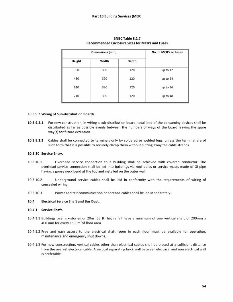
Part 10 Building Services (MEP)
54
BNBC Table 8.2.7 Recommended Enclosure Sizes for MCB's and Fuses
Dimensions (mm) No. of MCB's or Fuses
Height Width Depth
350 390 120 up to 12
480 390 120 up to 24
610 390 120 up to 36
740 390 120 up to 48
10.3.9.2 Wiring of Sub-‐distribution Boards.
10.3.9.2.1 For new construction, in wiring a sub-‐distribution board, total load of the consuming devices shall be distributed as far as possible evenly between the numbers of ways of the board leaving the spare way(s) for future extension.
10.3.9.2.2 Cables shall be connected to terminals only by soldered or welded lugs, unless the terminal are of such form that it is possible to securely clamp them without cutting away the cable strands.
10.3.10 Service Entry.
10.3.10.1 Overhead service connection to a building shall be achieved with covered conductor. The overhead service connection shall be led into buildings via roof poles or service masts made of GI pipe having a goose neck bend at the top and installed on the outer wall.
10.3.10.2 Underground service cables shall be laid in conformity with the requirements of wiring of concealed wiring.
10.3.10.3 Power and telecommunication or antenna cables shall be led in separately.
10.4 Electrical Service Shaft and Bus Duct.
10.4.1 Service Shaft.
10.4.1.1 Buildings over six-‐stories or 20m (65 ft) high shall have a minimum of one vertical shaft of 200mm x 400 mm for every 1500m2of floor area.
10.4.1.2 Free and easy access to the electrical shaft room in each floor must be available for operation, maintenance and emergency shut downs.
10.4.1.3 For new construction, vertical cables other than electrical cables shall be placed at a sufficient distance from the nearest electrical cable. A vertical separating brick wall between electrical and non electrical wall is preferable.

Part 10 Building Services (MEP)
55
10.4.1.4 For new construction, vertical service shaft for electrical risers must not be placed adjacent to the sanitary shafts. They should be placed at significant separation in order to ensure that the vertical service shaft for electrical risers remains absolutely dry.
10.4.2 Bus Duct.
10.4.2.1 Bus ducts should be used for exposed work or where concealing is not of a permanent nature. The bus duct shall be laid with minimum numbers of bends for distribution system. Typical rating of feeder bus ducts for 3-‐phase, 3-‐wire or 4-‐wire system shall range from 200 amperes to 3000 amperes. Concrete horizontal ducts of suitable size shall be provided along the roads for a group of buildings to be fed by a single substation.
10.4.2.2 Floors of the duct area shall be constructed in such a way so that the empty space after putting the cables/bus-‐bar trunking/pipes/conduits in position the remaining open space is filled up with RCC slab(s) or any other non inflammable material so that fire or molten PVC cannot fall from one floor to the next lower floor(s). For this purpose arrangements need to be made during the main floor casting.
10.4.2.3 Components of the bus duct shall be vermin and damp-‐proof and all openings shall be sealed with noncombustible materials.
10.4.3 Sealing of Shaft and Duct.
10.4.3.1 Where a wiring system passes through elements of building construction such as floors, walls, roofs, ceilings, partitions or cavity barriers, the openings remaining after passage of the wiring system shall be sealed according to the degree of fire resistance prescribed for the respective element of building construction before penetration.
10.4.3.2 Wiring systems which penetrate elements of building construction having specified fire resistance shall be internally sealed to the degree of fire resistance of the respective element before penetration as well as being externally sealed.
10.5 Electrical Substation.
10.5.1 General.
10.5.1.1 Necessity and capacity of the electrical substation shall be set by regulations in the Electricity Act or by the relevant electrical utilities.
10.5.1.2 For new construction, to arrive at the capacity of the substation required, a load factor of 70% shall be applied to the estimated load of the building, unless future expansion requirements dictate that a higher figure be considered.
10.5.2 Substation Location.
10.5.2.1 For new construction, the substation shall be installed on the lowest floor level. Location of substation in the basement floor should be avoided. Direct access from the street for installation or removal of the equipment shall be provided.
10.5.2.2 The floor level of the substation or switch room shall be above the highest flood level of the locality. Suitable arrangements should exist to prevent the entrance of storm or flood water into the substation area.

Part 10 Building Services (MEP)
56
10.5.2.3 For new construction, in the case of a building complex, or a group of buildings belonging to the same organization, the substation should preferably be located in a separate building and should be adjacent to the generator room, if any.
10.5.2.4 For new construction, if the electric substation has to be located within the main building for unavoidable reasons, it should be located on ground floor.
10.5.2.5 For transformers having large oil content (more than 2000 liters), soak pits are to be provided.
10.5.2.6 For new construction, the minimum height of the substation room shall be 3.6 m (12 ft). The minimum area required for substation and transformer rooms for different capacities are given in BNBC Table 8.2.8.
10.5.2.7 For existing construction, sufficient access and working space to permit safe operation and maintenance of the equipment within the sub-‐station shall be no less than 1.07 m (3ft 6in).
BNBC Table 8.2.8 Area Required for Transformer Room and Substation for Different Capacities
Capacity of Transformer
(kVA)
Transformer Room Area
(m2)
Total Substation Area (with HT, LT Panels & Transformer Room but without Generators)
(m2)
1x150 12 42
1x250 13 45
2x250 26 90
1x400 13 45
2x400 26 90
3x400 39 135
2x630 26 90
3x630 39 135
2x1000 26 90
3x1000 39 135
10.5.3 Layout of Substation.
10.5.3.1 For new construction, the layout of the substation shall be in accordance of the power flow, i.e. from utility network to HT room, then to transformer and finally to the low voltage switchgear room. In general, the substation HT to LT Transformer shall be placed in one corner of the room so that the HT side remains away from the passage of the persons.
10.5.3.2 For new construction, the HT metering panel shall be located near the exterior of the substation room near the exit gate and also shall be convenient for the HT cable entry.
10.5.3.3 For new construction, the HT Panel shall be located near the exterior, just after or adjacent to the HT panel.

Part 10 Building Services (MEP)
57
10.5.3.4 For new construction, the LT Panel shall remain at a sufficient distance from the transformer but not too far away from the transformer. The location of the LT panel should such that the riser main cable can have their way upward or outward within very short distance.
10.5.3.5 For new and existing construction, all the rooms shall be provided with partitions up to the ceiling and shall have proper ventilation. Transformer rooms shall have proper ventilation and where necessary louvers at lower level and exhaust fans at higher level shall be provided at suitable locations in such a way that cross ventilation is maintained.
10.5.3.6 For new and existing construction, arrangement shall be made to prevent storm water entering the transformer and switch rooms through the soak pits, if floor level of the substation is low.
10.6 Equipment and Accessories.
10.6.1 High-‐voltage Switchgear.
10.6.1.1 For new construction, banks of switchgears shall be segregated from each other by means of fire resistant barriers in order to prevent the risk of damage by fire or explosion arising from switch failure. Where 3 bus-‐section switch is installed, it shall also be segregated from adjoining banks in the same way.
10.6.1.2 For new construction, in the case of duplicate or ring main supply, switches with interlocking arrangement shall be provided to prevent simultaneous switching of two different supply sources.
10.6.2 Low-‐voltage Switchgear.
10.6.2.1 Switchgear and fuse gear must have adequate breaking capacity in relation to the capacity of the transformers.
10.6.2.2 For new and existing construction, isolation and protection of outgoing circuits forming the main distribution system may be effected by means of circuit breakers, or fuses or switch fuse units, mounted on the main switchboard, the choice between alternative types of equipment will take the following points into consideration: (1) In certain installations supplied with electric power from remote transformer substations, it may be
necessary to protect main circuits with circuit breakers operated by earth leakage trips in order to ensure effective earth fault protection.
(2) Where large electric motors, furnaces or other heavy electrical equipment are installed, the main circuits shall be protected by metal clad circuit breakers or conductors fitted with suitable instantaneous and time delay over current devices together with earth leakage and backup protection where necessary.
(3) In installations other than those mentioned above or where overloading of circuits may be considered unlikely, HRC type fuses will normally afford adequate protection for main circuits separately as required; the fuses shall be mounted in switch fuse unit or with switches forming part of the main switch boards.
(4) Where it is necessary to provide suitable connection for power factor improvement capacitors at the substation bus, suitable capacitors shall be selected in consultation with the capacitor and switchgear manufacturer and necessary switchgear/feeder circuit breaker shall be provided for controlling the capacitor bank(s).

Part 10 Building Services (MEP)
58
10.6.3 Transformers.
10.6.3.1 For new construction, in most cases oil type natural cooled transformer may be used for substations if adequate space is available to accommodate the transformer.
10.6.3.2 For new construction, dry type transformer should be installed where risk of spreading of fire is high and where flammable materials are to be kept around the substation.
10.6.3.3 For new construction, where two or more transformers are to be installed in a substation to supply a medium voltage distribution system, the distribution system shall be divided into separate sections each of which shall normally be fed from one transformer only unless the medium voltage switchgear has the requisite short circuit capacity, provision may be made to interconnect separate sections through bus couplers to cater for the failure or disconnection of one transformer.
10.6.3.4 For new construction, the transformers that at any time operate in parallel shall be so selected as to share the load in proportion to their respective ratings.
10.6.3.5 For new construction, when a step-‐up transformer is used, a linked switch shall be provided for disconnecting the transformer from all poles of the supply, including the neutral conductor.
10.6.4 Rotating Machines.
10.6.4.1 All equipment including cables of every circuit carrying the starting, accelerating and load currents of motors shall be suitable for a current at least equal to the full load current rating of the motor. When the motor is intended for intermittent duty and frequent stopping and starting, account shall be taken of any cumulative effects of the starting periods upon the temperature rise of the equipment of the circuit.
10.6.4.2 The rating of circuit supplying the rotors through slip ring or commutator of induction motors shall be suitable for both the starting and loaded conditions. Every electric motor having a rating exceeding 0.376 kW shall be provided with control equipment incorporating means of protection against overcurrent.
10.6.4.3 Every motor shall be provided with means to prevent automatic restarting after a stoppage due to drop in voltage or failure. This requirement does not apply to any special cases where the failure of the motor to start after a brief interruption of the supply would be likely to cause greater danger. It also does not preclude arrangements for starting a motor at intervals by an automatic control device where other adequate precautions are taken against danger from unexpected restarting.
10.6.4.4 The frame of every stationary motor shall be connected with earth.
10.6.5 Cables.
10.6.5.1 For new construction, the advice of the cable manufacturer with regard to installation, jointing and sealing shall be followed.
10.6.5.2 The HT cables shall either be laid on cable racks or in built-‐up concrete trenches/tunnel/ basement or directly buried in the ground. Standard cable laying techniques shall be used.
10.6.5.3 Methods of installation of cables and conductors in common use as specified in BNBC Table 8.2.10 shall be followed.
10.7 Main Switch, Switchboards And Metal Clad Switchgear.
10.7.1 Main Switch, Switchboards.
Part 10 Building Services (MEP)
59
10.7.1.1 All main switches shall be either of metal clad enclosed patterns or of any insulated enclosed pattern and the switches shall be fixed at close proximity to the point of entry of supply.
10.7.1.2 The wiring throughout the installation shall be such that there is no break in the neutral wire in the form a switch or fuse unit or otherwise.
10.7.1.3 The location of the main board shall be such that it is easily accessible for firemen and other personnel to quickly disconnect the supply in case of emergencies.
10.7.1.4 Open type switchboards are not allowed.
10.7.1.5 In damp situation or where inflammable or explosive dust, vapor or gas is likely to be present, the switchboard shall be totally enclosed or made flame proof as may be necessitated by the particular circumstances.
10.7.1.6 Switchboards shall not be erected above gas stoves or sinks or within 2.5m (8 ft) of any washing unit in the washing rooms or laundries.
10.7.1.7 In case of switchboards being unavoidable in places likely to be exposed to weather, to drip or in abnormally moist atmosphere, the outer casing shall be weather proof and shall be provided with glands or bushings or adapted to receive screwed conduit.
10.7.1.8 Adequate illumination shall be provided for all working spaces about the switchboards when installed indoors.
10.7.1.9 All metal casings or metallic coverings containing or protecting any electrical supply-‐line or apparatus shall be connected with earth.
10.7.1.10 There shall be a distance of 1 m (39 in.) clear in front of the switchboards and switchgear.
10.7.2 Metal Clad Switchgear.
10.7.2.1 Metal clad switchgear shall be mounted on hinged type metal boards or fixed type metal boards.
10.7.2.2 Hinged type metal boards shall consist of a box made of sheet metal not less than 2 mm thick and shall be provided with a hinged cover to enable the board to swing open for examination of the wiring at the back. The joints shall be welded. The board shall be securely fixed to the wall by means of rag bolt plugs and shall be provided with locking arrangement and earthing stud. All wires passing though the metal board shall be protected by a rubber bush at the entry hole. The earth stud should be commensurate with the size of the earth lead(s).
10.7.2.3 Fixed type metal boards shall consist of an angle or channel steel frame fixed on the wall at the top, if necessary.
10.7.2.4 There shall be a distance of 1m (39 in.) clear in front of the switchboards and switchgear.
10.7.3 Location of Distribution Boards.
10.7.3.1 For new construction, the distribution fuse boards shall be located as near as possible to the center of the load they are intended to control.
10.7.3.2 They shall be fixed on suitable stanchion or wall and shall be accessible -‐ for replacement of fuses, and shall not be more than 2m (6.5 ft) from floor level.

Part 10 Building Services (MEP)
60
10.7.3.3 For new and existing construction distribution panels shall be either metal clad type, or all insulated type. But if exposed to weather or damp situations, they shall be of the weather proof type and if installed where exposed to explosive dust, vapor or gas, they shall be of flame proof type. In corrosive atmospheres they shall be treated with anticorrosive preservative or covered with suitable plastic compounds.
10.7.3.4 Where two of more distribution fuse-‐boards feeding low voltage circuits are fed from a supply of medium voltage, these distribution boards shall be:
(1) fixed not less than 2m apart, or (2) arranged so that it is not possible to open two at a time, namely they, are interlocked, and the metal
case is marked "Danger 400 Volts" and identified with proper phase marking and danger marks, or (3) installed in rooms or enclosures accessible to authorized persons only.
10.7.3.5 All distribution boards shall be marked "Lighting" or "Power", as the case may be, and also be marked with the voltage and number of phases of the supply. Each shall be provided with a circuit list giving diagram of each circuit which it controls and the current rating for the circuit and size of fuse element.
10.7.3.6 There shall be a distance of 1 m (39 in.) clear in front of the distribution panels.
10.8 Standby Power.
10.8.1 General. Provision should be made for standby power supply to avert panic, hazard to life and property or major production loss in case of interruption of electrical power supply. The standby power supply may be a petrol engine or diesel engine or gas engine generator or an IPS or a UPS.
10.8.2 Capacity of a Standby Generating Set.
10.8.2.1 The capacity of standby generating set shall be chosen on the basis of essential light load, essential air-‐conditioning load, essential equipment load and essential services load, such as one lift out of a bank of lifts, one or all water pumps, etc. The generator shall be capable of taking starting currents of all the machines and circuits stated above simultaneously.
10.8.2.2 The generator frame shall be earthed by two separate and distinct connections to earth.
10.8.3 Standby Power for Lifts.
10.8.3.1 In a building, where a lift is installed, stand by power shall be provided by a self-‐contained generator set to operate automatically whenever there is a disruption of electrical power supply to the building.
10.8.3.2 Where only one lift is installed, the lift shall transfer to standby power within 60 seconds after failure of normal power.
10.8.3.3 Where two or more lifts are controlled by a common operating system, all lifts may be transferred to standby power within 60 seconds after failure of normal power, or if the stand by power source is of insufficient capacity to operate all lifts at the same time, all lifts shall be transferred to standby power in sequence, shall return to designated landing and discharge their load.
10.8.4 Generator Room.
10.8.4.1 For new construction, the generating set should preferably be housed in the substation building or should be placed adjacent to the substation room to enable transfer of electrical load with negligible voltage drop as well as to avoid transfer of vibration and noise to the main building.
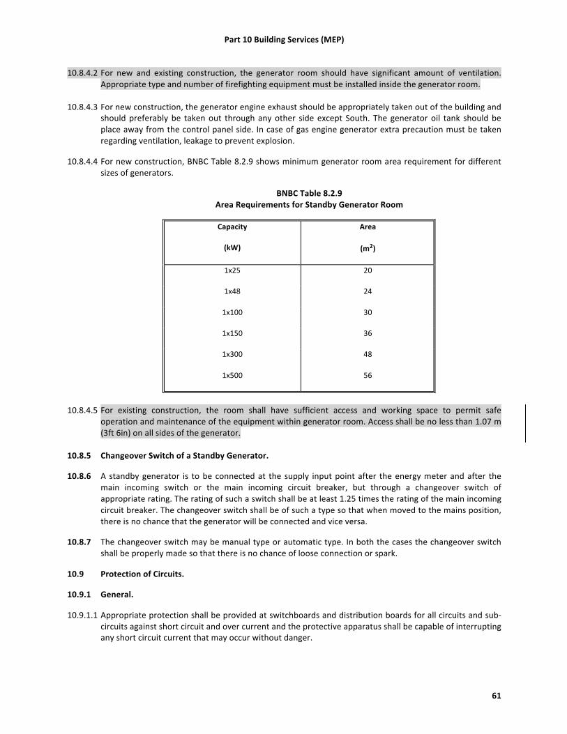
Part 10 Building Services (MEP)
61
10.8.4.2 For new and existing construction, the generator room should have significant amount of ventilation. Appropriate type and number of firefighting equipment must be installed inside the generator room.
10.8.4.3 For new construction, the generator engine exhaust should be appropriately taken out of the building and should preferably be taken out through any other side except South. The generator oil tank should be place away from the control panel side. In case of gas engine generator extra precaution must be taken regarding ventilation, leakage to prevent explosion.
10.8.4.4 For new construction, BNBC Table 8.2.9 shows minimum generator room area requirement for different sizes of generators.
BNBC Table 8.2.9 Area Requirements for Standby Generator Room
Capacity
(kW)
Area
(m2)
1x25 20
1x48 24
1x100 30
1x150 36
1x300 48
1x500 56
10.8.4.5 For existing construction, the room shall have sufficient access and working space to permit safe
operation and maintenance of the equipment within generator room. Access shall be no less than 1.07 m (3ft 6in) on all sides of the generator.
10.8.5 Changeover Switch of a Standby Generator.
10.8.6 A standby generator is to be connected at the supply input point after the energy meter and after the main incoming switch or the main incoming circuit breaker, but through a changeover switch of appropriate rating. The rating of such a switch shall be at least 1.25 times the rating of the main incoming circuit breaker. The changeover switch shall be of such a type so that when moved to the mains position, there is no chance that the generator will be connected and vice versa.
10.8.7 The changeover switch may be manual type or automatic type. In both the cases the changeover switch shall be properly made so that there is no chance of loose connection or spark.
10.9 Protection of Circuits.
10.9.1 General.
10.9.1.1 Appropriate protection shall be provided at switchboards and distribution boards for all circuits and sub-‐circuits against short circuit and over current and the protective apparatus shall be capable of interrupting any short circuit current that may occur without danger.

Part 10 Building Services (MEP)
62
10.9.1.2 Where circuit breakers are used for protection of main circuit and the sub-‐circuits derived therefrom, discrimination in operation shall be achieved by adjusting the protective devices of the sub-‐circuit breakers to operate at lower current settings and shorter time-‐lag than the main circuit breaker.
10.9.1.3 A fuse carrier shall not be fitted with a fuse element larger than that for which the carrier is designed. The current rating of fuses shall not exceed the current rating of the smallest cable in the circuit protected by the fuse.
10.9.2 Protection against Overload Current.
10.9.2.1 Protective devices shall be provided to break any overload current flowing in the circuit conductors before such a current could cause a temperature rise detrimental to insulation, joints, terminations or surroundings of the conductors.
10.9.2.2 The omission of devices for protection against overload is recommended for circuits supplying current-‐using equipment where unexpected opening of the circuit could cause danger, for example, the fire pump circuit.
10.9.3 Protection against Short-‐Circuit Currents. Protective devices shall be provided to break any short-‐circuit current flowing in the circuit conductors before such a current could cause danger due to thermal and mechanical effects produced in conductors and connections.
10.9.4 Protection against Under voltage.
10.9.4.1 Where a drop in voltage, or a loss and subsequent restoration of voltage could imply dangerous situations for persons and property, suitable precautions shall be taken.
10.9.4.2 An under voltage protective device is not required if damage to the installation is considered to be an acceptable risk, provided that no danger is caused to persons.
10.10 Earthing.
10.10.1 General. In general all parts of equipment and installation other than live parts shall be earth potential, thus ensuring that persons coming in contact with these parts shall also be at earth potential at all times.
10.10.2 Circuit and System Earthing.
10.10.2.1 Circuit and system earthing shall limit excessive voltage from line surges from cross-‐overs with higher voltage lines or turn lighting and keep non-‐current carrying enclosures and equipment at zero potential with respect to earth.
10.10.2.2 The value of the earthing resistance shall be in accordance with the protective and functional requirements of the installation and be continuously effective.
10.10.2.3 Where a number of installations have separate earthing arrangements, protective conductors running between any two of the separate installations shall either be capable of carrying the maximum fault current likely to flow through them or be earthed within one installation only and insulated from the earthing arrangements of any other installation. In the latter circumstances, if the protective conductor forms part of cables the protective conductor shall be earthed only in the installation containing the associated protective device.

Part 10 Building Services (MEP)
63
10.10.3 Methods of Earthing.
10.10.3.1 General. The three main elements required for an earthing system are earth conductors, earthing lead and earth electrodes.
10.10.3.2 Earth Conductors.
10.10.3.2.1 Earth conductors are the part of the earthing system which joins all the metal parts of an installation.
10.10.3.2.2 In all cases the grounding conductor shall be made of copper or galvanized steel or other metals or combination of metals which will not corrode excessively and, if practical, shall be without joints or splice. If joints are unavoidable, they shall be made and maintained so as not to materially increase the resistance of the earthing conductor and shall have appropriate mechanical and corrosion resistant characteristics.
10.10.3.2.3 Aluminum or copper clad aluminum conductors shall not be used for final connections to earth electrodes.
10.10.3.2.4 The earth conductor shall have a short time capacity adequate for the fault current which can flow in the grounding conductor or conductors for the operating time of the system protective device. In case of copper wire being used as earth conductors, the size of the wire shall not be less than half the area of the largest current carrying conductor supplying the circuit.
10.10.3.2.5 BNBC Table 8.2.11 gives the minimum sizes of copper earth conductors corresponding to the sizes of associated copper circuit conductors. No size smaller titan 14 SWG shall be used anywhere as earth conductor.
BNBC Table 8.2.11 Minimum Cross-‐sectional Area of Copper Earth Conductors in Relation to
the Area of Associated Phase Conductors
Cross-‐sectional Area of Phase Conductor(s)
(mm2)
Minimum Cross-‐sectional Area of the Corresponding Earth Conductor
(mm2)
Less than 16
16 or greater but less than 35
35 or greater
Same as cross-‐sectional area of phase conductor but not less than 14 SWG
16
Half the cross-‐sectional area of phase conductor
Part 10 Building Services (MEP)
64
10.10.3.3 Earth Lead.
10.10.3.3.1 The earth conductor shall be brought to one or more connecting points according to size of installation; the copper wire earthing leads shall run from there to the electrodes.
10.10.3.3.2 Earthing lead can either be of copper wire or of copper strands.
10.10.3.3.3 Earthing leads shall be run in duplicate down to the earth electrode so as to increase the safety factor of the installation. Copper wire used as earthing lead must not be smaller than 8 SWG (12 mm2).
10.10.3.4 Earth Electrodes.
10.10.3.4.1 The earth electrode shall as far as practicable penetrate into permanently moist soil preferably below ground water table. The resistance of the electrodes shall not be more than one ohm.
10.10.3.4.2 The following types earth electrodes are recognized:Copper rods, copper plates, galvanized iron pipes.
10.10.3.4.3 The following is a guideline for electrode size: Copper rods shall have a minimum diameter of 12.7 mm,GI pipes shall have a minimum diameter of 50mm, copper plates shall not be less than 600 mm x 600mm in size, with 6mm thickness.
10.11 Lightning Protection.
10.11.1General. Lightning Protection shall be provided for in accordance with the following:
10.11.1.1 New building shall have protection against lightning depending on the probability of a stroke and acceptable risk levels. Steps shall be taken for an objective assessment of the risk and of the magnitude of the consequences of lightning strikes following BNBC Part 8, section 2.9. The marginal Risk Index shall be 40. Structures higher than 53 m (174 ft) require protection in all cases.
10.11.1.2 A complete lightning protection system shall consist of air termination network, down conductors and earth termination.
10.11.1.3 A lighting protection system shall be required for existing construction if the marginal Risk Index is 40 or greater and the structure is higher than 53 m (174 ft)
10.11.2 Air Termination Network. The air termination network is that part which is intended to intercept lightning discharges. It consists of vertical and horizontal conductors arranged to protect the required area. No part of the roof should be more than 9m (30 ft) from the nearest horizontal conductor except that an additional 0.3 m (1 ft) may be added for each 0.3m (1 ft) or part thereof by which the part to be protected is below the nearest conductor.
10.11.3 Down Conductor.
10.11.3.1 The down conductor is the conductor which runs from the air termination to the earth termination. A building with a base area not exceeding 100 m2(1,076 ft2) shall be provided with one down conductor. For a large building there shall be one down conductor for the first 100m2(1,076 ft2) plus a further one for every 300m2 or part thereof in excess of the first 100 m2 (1,076 ft2). Alternatively, for a larger building one down conductor may be provided for every 30m (100 ft) of perimeter. The number chosen can be the smaller of the numbers given by these alternative methods of calculation.

Part 10 Building Services (MEP)
65
10.11.3.2 The material used for lightning conductors must be aluminum or copper. The criterion for design is to keep the resistance from air termination to earth to a minimum.
10.11.4 Earth Termination.
10.11.4.1 The earth termination is that part which discharges the current into the general mass of the earth. The total resistance of an electrode for a lightning protection system must not exceed 10 ohms.
10.11.4.2 The lightning protection system ground terminals shall be bonded to the building or structure grounding electrode system.
10.11.4.3 Recommended dimensions for various components of lightning arrester are given in Table 4.6. Larger conductors should however be used if the system is unlikely to receive regular inspection and maintenance.
BNBC Table 8.2.14 Sizes of the Components of Lightning Protection Systems
Components Minimum Dimensions
Air Terminations
Aluminum and copper strip
Aluminum, aluminum alloy, copper and phosphor bronze rods
Stranded aluminum conductors
Standard copper conductors
20 mm x 3 mm
10 mm dia
19 strands of 2.5 mm
19 strands of 1.8 mm
Down Conductors
Aluminum and copper strip
Aluminum, aluminum alloy and copper rods
20 mm x 3 mm
10 mm dia
Earth Terminations
Hard drawn copper rods for driving into soft ground
Hard drawn or annealed copper rods for indirect driving or laying in ground
Phosphor bronze for hard ground
Copper clad steel for hard ground
12 mm dia
10 mm dia
12 mm dia
10 mm dia

Part 10 Building Services (MEP)
66
10.11.4.4 External metal on a building should be bonded to the lightning conductor with bonds at least as large as the conductor.
10.12 Illumination of Exit Signs and Means Of Escape.
10.12.1 Exit Signs.
10.12.1.1 All required exit signs shall be illuminated continuously at all times.
10.12.1.2 Exit signs may be illuminated either by lamps external to the sign or by lamps contained within the sign. The source of illumination shall provide not less than 50 lux at the illuminated surface with a contrast of not less than 0.5. Approved self-‐luminous signs which provide evenly illuminated letters having a minimum luminance of 0.2cd/m2 may also be used.
10.12.1.3 Emergency power. Lighting for exit signs shall either be provided with emergency power or battery backup.
10.12.1.4 Inspection and testing. Emergency power for exit signs shall be verified at least once per year. If battery-‐operated signs are used, these lights shall be tested on a monthly basis. Functional testing of battery powered signs shall be provided for a minimum 90 min once per year.
10.12.2 Means of egress.
10.12.2.1 Illumination. The means of egress paths shall be illuminated at all times the building is occupied. Illumination shall be a minimum of 10 lux for all corridors, exit doors, and stairways. Aisles shall be provided with a minimum 2.5 lux.
10.12.2.2 Emergency power. Means of egress illumination shall be provided with emergency power or supplemented with battery powered lights that provide minimum 10 lux for no less than 30 min in the event of failure of normal lighting.
10.12.2.3 Inspection and testing. Emergency power for means of egress illumination shall be verified at least once per year. If battery operated lights are used, these lights shall be tested on a monthly basis. Functional testing of battery powered lights shall be provided for a minimum 30 min once per year.
10.12.3 Battery Systems. Battery systems used to provide standby or emergency power shall be installed, tested and maintained in accordance with NFPA 111.
10.12.4 Generators. Generators used to provide standby or emergency power shall be installed, tested, and maintained in accordance with NFPA 110.
10.13 Inspection and Testing.
10.13.1 General. Every installation shall, on completion and before being energized, be inspected and tested. The methods of test shall be such that no danger to persons or property or damage to equipment occurs even if the circuit tested is defective.
10.13.2 Periodic Inspection and Testing. Periodic inspection and testing shall be carried out in order to maintain the installation in a sound condition after putting it into service. Where an addition is to be made to the fixed wiring of an existing installation, the latter shall be examined for compliance with the recommendations of this Standard.
10.13.2.1 The periodic inspection and testing program shall generally comply with the requirements of NFPA 70E®, Standard for Electrical Safety in the Workplace®, 2012 Edition
Part 10 Building Services (MEP)
67
10.13.2.2 For existing construction, thermographic inspection of electrical equipment shall be provided on a tri-‐annual basis. The thermographic inspection shall be carried out in general accordance with ASTME1934-‐99a Standard Guide for Examining Electrical and Mechanical Equipment with Infrared thermography.
10.13.3 Checking the conformity with the Bangladesh Standard. The individual equipment and materials which form part of the installation shall generally conform to the relevant Bangladesh Standard (BDS) wherever applicable. If there is no relevant Bangladesh standard specification for any item, these shall be approved by the appropriate authority.
10.13.4 Insulation Tests.
10.13.4.1 For new installations, insulation resistance test shall be made on all electrical equipment, using a self-‐ contained instrument such as the direct indicating ohm-‐meter of the generator type. DC potential shall be used in these tests and shall be as follows or an appropriate Meggar:
(1) Circuits below 230 volts 500 volts Meggar (2) Circuits between 230 volts to 400 volts 1000 volts Meggar
10.13.4.2 The minimum acceptable insulation resistance value is 5 mega ohms for LT lines. Before making connections at the ends of each cable run, the insulation resistance measurement test of each cable shall be made. Each conductor of a multi-‐core cable shall be tested individually to all other conductors of the group and also to earth. If insulation resistance test readings are found to be less than the specified minimum in any conductor, the entire cable shall be replaced.
10.13.4.3 All transformers, switchgears etc. shall be subject to an insulation resistance measurement test to ground after installation but before any wiring is connected. Insulation tests shall be made between open contacts of circuit breakers, switches etc. and between each phase and earth.
10.13.4.4 For existing construction, insulation resistance test shall be made on all electrical equipment as prescribed in 10.13.4.1 on a 5 year cycle. If the insulation resistance test was not completed at the time of installation, the testing shall be completed at this time.
10.13.5 Earth Resistance Test.
10.13.5.1 Earth resistance tests shall be made on the system, separating and reconnecting each earth connection using earth resistance meter.
10.13.5.2 The electrical resistance of the earth continuity conductor together with the resistance of the earthing lead measured from the connection with the earth electrode to any other position in the completed installation shall not exceed 1 ohm.
10.13.5.3 Where more than one earthing sets are installed, the earth resistance between two sets shall be measured by means of resistance bridge instrument. The earth resistance between two sets shall not exceed 1 ohm.
10.13.5.4 For existing construction, earth resistance test shall be made on the system as prescribed in 10.13.5 on a 5 year cycle. If the earth resistance test was not completed at the time of installation, the testing shall be completed at this time.
10.13.6 Operation Tests. Current load measurement shall be made on equipment and on all power and lighting feeders. The current reading shall be taken in each phase wire and in each neutral wire while the circuit or equipment is operating under actual load conditions. Clamp on ammeters may be used to take current

Part 10 Building Services (MEP)
68
readings without interrupting a circuit. All light fittings shall be tested electrically and mechanically to check whether they comply with the standard specifications. Fluorescent light fittings shall be tested so that when functioning no flickering or choke singing is felt.
10.13.7 Inspection of the Installation. On completion of wiring a general inspection shall be carried out by competent personnel in order to verify that the provisions of this Standard and that of the Electricity Act of Bangladesh have been complied with.
10.13.7.1 Inspection of Substation Installations. In substation installations, it shall be checked whether:
(1) Phase to phase and phase to earth clearances are provided as required; (2) All equipment are efficiently earthed and properly connected to the required number of earth
electrodes; (3) The required ground clearance to live terminals is provided (4) Suitable fencing is provided with gate with lockable arrangements; (5) The required number of caution boards, fire-‐fighting equipment, operating rods, rubber mats, etc.,
are kept in the substation; (6) In case of indoor substation sufficient ventilation and draining arrangements are made; (7) All cable trenches have covers of noninflammable material; (8) Free accessibility is provided for all equipment for normal operation; (9) All name plates are fixed and the equipment are fully painted; (10) All construction materials and temporary connections are removed; (11) Oil level , bus bar tightness, transformer tap position, etc. are in order; (12) Earth pipe troughs and cover slabs are provided for earth electrodes/earth pits and the neutral and
LA earth pits are marked for easy identification; (13) Earth electrodes are of GI pipes or CI pipes or copper plates. For earth connections, brass bolts and
nuts with lead washers are provided in the pipes/plates; (14) Earth pipe troughs and oil sumps/pits are free from rubbish, dirt and stone jelly and the earth
connections are visible and easily accessible; (15) HT and LT panels and switchgears are all vermin and damp-‐ proof and all unused openings or holes
are blocked properly; (16) The earth bus bars have tight connections and corrosion free joint surfaces; (17) Control switch fuses are provided at an accessible height from ground; (18) Adequate headroom is available in the transformer room for easy topping-‐ up of oil, maintenance,
etc.; (19) Safety devices, horizontal and vertical barriers, bus bar covers/shrouds, automatic safety
shutters/door interlock, handle interlock etc. are safe and in reliable operation in all panels and cubicles;
(20) Clearances in the front, rear and sides of the main HT and LT and sub-‐switch boards are adequate; (21) The switches operate freely; the 3 blades make contact at the same time, the arcing horns contact in
advance; and the handles are provided with locking arrangements, (22) Insulators are free from cracks, and are clean; (23) In transformers, there is no oil leak; (24) Connections to bushing in transformers are light and maintain good contact; (25) Bushings are free from cracks and are clean; (26) Accessories of transformers like breathers, vent pipe, buchholz relay, etc. are in order; (27) Connections to gas relay in transformers are in order; (28) In transformers, oil and winding temperature are set for specific requirements to pump out; (29) In case of cable cellars, adequate arrangements exist to pump off water that has entered due to
seepage or other reasons; and

Part 10 Building Services (MEP)
69
(30) All incoming and outgoing circuits of HT and LT panels are clearly and indelibly labeled for identifications.
10.13.7.2 Inspection of Medium Voltage Installation. In Medium Voltage (MV) Installations, it shall be checked whether:
(1) All blocking materials that are used for safe transportation in switchgears, contactors, relays, etc. are removed;
(2) All connections to the earthing system have provisions for periodical inspection; (3) Sharp cable bends are avoided and cables are taken in a smooth manner in the trenches or alongside
the walls and ceilings using suitable support clamps at regular intervals; (4) Suitable linked switch or circuit breaker or lockable push button is provided near the
motors/apparatus for controlling supply to the motor/apparatus in an easily accessible location; (5) Two separate and distinct earth connections are provided for the motor apparatus; (6) Control switch fuse is provided at an accessible height from ground for controlling supply to overhead
traveling crane, hoists, overhead bus bar trunking; (7) The metal rails on which the crane travels are electrically continuous and earthed and bonding of rails
and earthing at both ends are done; (8) Four-‐core cables are used for overhead travelling crane and portable equipment, the fourth core
being used for earthing, and separate supply for lighting circuit is taken; (9) If flexible metallic hose is used for wiring to motors and other equipment, the wiring is enclosed to
the full lengths, and the hose secured properly by approved means; (10) The cables are not taken through areas where they are likely to be damaged or chemically affected; (11) The screens and armors of the cables are earthed properly; (12) The belts of belt driven equipment are properly guarded; (13) Adequate precautions are taken to ensure that no live parts are so exposed as to cause danger; (14) Installed Ammeters and voltmeters work properly and are tested; and (15) The relays are inspected visually by moving covers for deposits of dusts or other foreign matter.
10.13.7.3 Inspection of Overhead Lines. For overhead lines, every care must be taken so that:
(1) All conductors and apparatus including live parts thereof are inaccessible; (2) The types and size of supports are suitable for the overhead lines/conductors used and are in
accordance with approved drawing and standards; (3) Clearances from ground level to the lowest conductor of overhead lines, sag conditions, etc. are in
accordance with the relevant standard; (4) Where overhead lines cross the roads suitable grounded guarding shall be provided at road crossings, (5) Where overhead lines cross each other or are in proximity with one another, suitable guarding shall
be provided at crossings to protect against possibility of the lines coming in contact with one another; (6) Every guard wire shall be properly grounded / earthed; (7) The type, size and suitability of the guarding arrangement provided shall be adequate; (8) Stays cables must be provided suitably with the overhead line carrying poles as required and shall be
efficiently earthed at the bottom and shall be provided with suitable stay insulators of appropriate voltages;
(9) Anti-‐climbing devices and Danger Board/Caution Board Notices are provided on all HT supports; (10) Clearances along the route are checked and all obstructions such as trees/branches and shrubs are
cleared on the route to the required distance on either side; (11) Clearance between the live conductor and the earthed metal parts are adequate; and (12) For the service connections tapped off from the overhead lines, cutouts of adequate capacity are
provided.

Part 10 Building Services (MEP)
70
10.13.7.4 Inspection of Lighting Circuits. The lighting circuits shall be checked to see whether:
(1) Wooden boxes and panels are avoided in factories for mounting the lighting boards, switch controls, etc.;
(2) Neutral links are provided in double pole switch fuses which are used for lighting control, and no fuse is provided in the neutral;
(3) The plug points in the lighting circuit are all 3-‐ pin type, the third pin being suitably earthed; (4) Tamper proof interlocked switch socket and plug are used for locations easily accessible; (5) Lighting wiring in factory area is enclosed in conduit and the conduit is properly earthed, or
alternatively, armored cable wiring is used; (6) A separate earth wire is run in the lighting installation to provide earthing for plug points, fixtures and
equipment; (7) Proper connectors and junction boxes are used wherever joints are in conductors or cross-‐over of
conductors takes place; (8) Cartridge fuse units are fitted with cartridge fuses only.
10.13.8 Electrical Inspections.
10.13.8.1 Records of initial testing as well as subsequent testing shall be maintained onsite.
10.14 Elevators
10.14.1 General. Elevators shall be installed in accordance with BNBC Part 8 Chapter 5 and 5.9 of this Standard.
10.15 Naked lights.
10.15.1 Light fixtures without protective covers (otherwise known as naked lights) shall not be allowed in storage areas or in any area where the Inspector of the Factories Rules (1.6.3.7) Part 53 disallows these fixtures.
10.15.2 Signs shall be posted in Bengali and English, indicating this prohibition at all entrances to these areas.
10.15.3 Lighting shall not be removed from storage areas.
10.16 Electrical Safety Program. An Electrical Safety Program shall be developed in order to properly train the competent personnel who are responsible for operating and maintaining the electrical systems. The program shall generally conform to the requirements of NFPA 70E®, Standard for Electrical Safety in the Workplace or comparable standard.

Part 11 Alterations/Change of Use
71
11 Part 11 Alterations/Change of Use
11.1 Alterations. Delete Part 9 of the 2006 (BNBC Code in Its entirety. Substitute Part 9 of the 2012 (BNBC Code (draft) in its entirety.
11.2 General. BNBC 2012 (draft) Part 9 Section 1.1. The provisions of this part are intended to maintain or increase the current degree of public safety as well as health and general welfare in existing buildings while permitting alteration, addition to or change of use. See Part 8 of the BNBC for requirements related to the design of expansions and alterations of existing factories.
11.3 General. BNBC 2012 (draft) Part 9 Section 1.2.1. The provision of this part shall apply to existing buildings that will continue to be or are proposed to be in occupancy groups B, E, F, G, H, J, and K..
11.4 Change in use. BNBC 2012 (draft) Part 9 Section 1.2.2
11.4.1 BNBC 2012 (draft) Part 9 Section 1.2.2.1. No change in use of any existing factory without prior notification to the Chief safety Inspector.
11.4.2 BNBC 2012 (draft) Part 9 Section 1.2.2.3.Where an existing building is changed to a new use group classification, the provisions for the new use group in the BNBC shall be used to determine compliance.
11.5 Change in use. BNBC 2012 (draft) Part 9 Section 1.2.3
11.5.1 BNBC 2012 (draft) Part 9 Section1.2.3.1. No change in use of any part of any existing factory without prior notification to the Chief Safety Inspector.
11.6 Additions. BNBC 2012 (draft) Part 9 Section 1.2.4.1. No addition to any existing buildings shall be made without permission from the permitting authority.
11.6.1 BNBC 2012 (draft) Part 9 Section1.2.4.2. Additions to existing buildings shall comply with all the requirements of the BNBC for new constructions as set forth in Part 3 of the BNBC and shall comply with fire requirements set forth in Part 4 of the BNBC.
11.7 BNBC 2012 (draft) Part 9 Section 1.2.4.3.The combined height and area of the existing buildings and new additions shall not exceed the height and open space requirements for new buildings specified in Part 3 of the BNBC.
11.8 BNBC 2012 (draft) Part 9 Section1.2.5.1. An existing building or portion thereof which does not comply with the requirements of the BNBC for new construction (BNBC Part 3) shall not be altered in such a manner that results in the building being less safe or sanitary than such building is at present.
11.9 BNBC 2012 (draft) Part 9 Section 1.2.6.1. Any construction within the site which does not have approval of the appropriate authority must be removed before any new addition, alteration or change of use is carried out. All other types of existing construction and their changes shall comply with sub clauses 1.2.4 and 1.2.5 of this Part 9 of the BNBC.
11.10 Investigation and Evaluation. BNBC 2012 (draft) Part 9 Section 1.3.1. For the proposed works relating to alteration, addition to and change of use, the owner of the building shall cause the existing buildings to be investigated and evaluated by competent professionals in accordance with the provisions of this Standard. For structural changes in use, the competent professional shall be a qualified structural engineer.
Part 11 Alterations/Change of Use
72
11.11 Structural Analysis. BNBC 2012 (draft) Part 9 Section 1.3.2.
11.11.1 BNBC 2012 (draft) Part 7 Section 1.3.2.1.The owner shall have a structural analysis of the existing building carried out by an qualified structural engineer to determine the adequacy of all structural systems for the proposed alteration, addition or change of use.
11.12 BNBC 2012 (draft) Part 9 Section2.1.1.1.The owner shall make any proposed factory modifications available for visual or analytical assessment by a third party.
11.12.1 BNBC 2012 (draft) Part 9 Section2.1.2.1. Additions or alterations to an existing building or structure are not to be made if such additions or alterations cause the building or structure to be unsafe or more hazardous based on fire safety, life and structural safety or environmental degradation.

Part 12 Existing Buildings
73
12 Part 12 Existing Buildings
12.1 General. The requirements of Part 9 of the 2006 BNBC are adopted in their entirety.

Part 13 Human Element Programs
74
13 Part 13 Human Element Programs
13.1 Fire Safety Director.
13.1.1 Duties. The duties of the Fire Safety Director shall include the following:
(1) Establish internal and external rally points and communicate to all employees in the building. (2) Fire department pre-‐planning. (3) Conduct safety inspections as outlined in 13.9. (4) Ensure all testing of fire protection equipment is conducted in accordance with 13.10.
13.2 Fire Drills
13.2.1 Fire drills shall be conducted on a quarterly basis as outlined in BNBC Part 4 Appendix A for all garment facilities.
13.2.2 Fire drills shall be conducted under the direction of a Fire Safety Director.
13.2.3 All other requirements for fire drills shall be conducted in accordance with BNBC Part 4 Appendix A.
13.3 Evacuation Plan.
13.3.1 The Fire Service Director shall develop a fire evacuation plan for each building.
13.3.2 Fire evacuation maps shall be posted at the entrance to each exit stair.
13.3.3 The evacuation plan shall include provisions to assist physically disabled persons. A list of all employees with physical disabilities shall be kept by the Fire Service Director.
13.4 Hot work permit.
13.4.1 A hot work permit system program shall be enacted for all RMG facilities in accordance with NFPA 51B.
13.5 Smoking.
13.5.1 Smoking shall be prohibited in any garment factory building, separate storage building, or any building or area where the Inspector of the Factories Rules (1.6.3.7) Part 53 requires that smoking be prohibited.
13.5.2 Signs shall be posted in Bengali and English at all building entrances.
13.5.3 If an Owner creates a designated smoking area outside the buildings, information on the location of these designated areas shall be posted on the signs required in 13.5.2.
13.6 Housekeeping.
13.6.1 Policy. Establish written corporate and plant policies on housekeeping to ensure scheduled cleaning for floor, wall, ceiling, supply and return air ventilation systems. Promptly reschedule skipped cleanings. Provide a documented line of authority for authorizing a cleaning delay and rescheduling. As a general rule the maximum tolerable deposit thickness for loose fluffy lint is 13 mm (½ in.) over a maximum of 46.5 m2 (500 ft2). Limit dense deposits to 6 mm (¼ in.) and oil saturated deposits to 3.2 mm (⅛ in.).
13.6.2 Maintain electrical systems in good working order and keep free of lint buildup to reduce the potential for ignition. This includes cleaning inside junction boxes, buses, trays, tunnels, etc.

Part 13 Human Element Programs
75
13.7 Storage practices.
13.7.1 Management of Operating Loads
13.7.1.1 Factory Owners shall ensure that at least one trained professional individual is assigned to each factory facility to manage and monitor the operational loadings of the building, including the following:
(1) storage of work materials (2) storage of work products (3) location and weights of fixed and non-‐fixed equipment
13.7.2 Cutting tables. Storage underneath the cutting tables shall be kept clear of combustibles at all time, except as provided for miscellaneous storage in accordance with 3.4.2.1.6 or where automatic sprinkler protection is installed. Where an automatic sprinkler system is installed sprinklers are required to be installed beneath cutting tables greater than 4 ft in width that are used for storage of combustibles.
13.8 Egress. All means of egress shall be kept free and clear at all times.
13.9 Safety Inspections. A safety inspection program shall be initiated and conducted on a quarterly basis. This program shall be conducted under the direction of the Fire Safety Director. These inspections shall look for egress maintenance, condition of fire doors, storage in aisle ways, excess storage, smoking, hot work and other fire-‐safety related items. Records of these inspections shall be kept for inspection review.
13.9.1 Construction inspections. An additional safety inspection program shall be initiated under the direction of the Fire Safety Director for any construction that occurs in an occupied facility (see Section 9.2).
13.9.2 Doors tested. Fire doors shall be tested on a quarterly basis to ensure that they are properly closing and latching. They shall also be checked for the proper label and verification that the door has not been damaged in any way.
13.10 Maintenance of fire protection equipment.
13.10.1 Automatic suppression systems. Inspection, testing and maintenance in accordance with NFPA 25 shall be conducted on all water-‐based fire protection systems.
13.10.2 Fire alarm and detections systems. Inspection, testing and maintenance in accordance with NFPA 72 shall be conducted on all fire alarm systems.
13.10.3 Fire extinguishers. Fire extinguishers shall be inspected, tested, and maintained in accordance with NFPA 10.
13.11 Equipment.
13.11.1 Establish a maintenance, cleaning and lubrication schedule for all equipment. The maintenance and cleaning schedule will vary with type of fiber processed and the equipment used. Lubricate equipment in accordance with manufacturer’s recommendations. Review plant fire loss records to determine whether cleaning or equipment maintenance was a factor, and increase frequency as needed.
13.12 Electrical maintenance.
13.12.1 Testing of emergency lighting. Emergency lighting provided by battery backup shall be tested on a monthly basis.

Part 13 Human Element Programs
76
13.12.2 Generators. Generators used for emergency or standby requirements of this Standard shall be inspected, tested, and maintained in accordance with NFPA 110.