
The Virginia Stream Restoration & Stabilization Best ... · The guide assumes readers have a basic...
207
The Virginia Stream Restoration & Stabilization Best Management Practices Guide Department of Conservation and Recreation Division of Soil and Water Conservation 203 Governor Street, Suite 206 Richmond, Virginia 23219-2094 Phone: 804-786-2064
Transcript of The Virginia Stream Restoration & Stabilization Best ... · The guide assumes readers have a basic...

The Virginia Stream Restoration & Stabilization
Best Management Practices Guide
Department of Conservation and RecreationDivision of Soil and Water Conservation
203 Governor Street, Suite 206Richmond, Virginia 23219-2094
Phone: 804-786-2064

This project was funded by the Virginia Coastal Program at the Department of Environmental Quality through grant number NA17OZ2355 of the National Oceanic and Atmospheric Administration, Office of Ocean and Coastal Resource Management under the Coastal Zone Management Act of 1972, as amended. This project was conducted as part of the Coastal Nonpoint Source Pollution Control Program administered by the Department of Conservation and Recreation.
The views expressed herein are those of the authors and do not necessarily reflect the views of NOAA or any of its subagencies or DEQ.
This project was completed with technical assistance from KCI Technologies, Inc and the Center for Environmental Studies at Virginia Commonwealth University.
2004
Cover photo depicts Jordan’s Branch, a tributary of the Chickahominy River in Henrico County, Virginia. Photo was taken by staff at Virginia Commonwealth University.

i
Table of Contents
TABLE OF CONTENTS……………………………………….………..…...…….....iAcknowledgements………………………………………………………………..iii
CHAPTER 1: INTRODUCTION………………………………………….......…….. 1Introduction……………………………………………….……………...................3 Permitting Issues and Processes……………………………………...................5
CHAPTER 2: DESIGN GUIDELINES…………………………….……........…….. 112.1 Introduction……………………………………………………….………….. 132.2 Fluvial Geomorphology Principles..……………………………………….. 132.3 Site Selection…….………………………………………..…………………. 172.4 Geomorphic Assessment…………………………………….…………….. 20 2.5 Stream Design Approaches………..………………………………………. 28
Analog Design……………………………………………………………………28 Empirical Design…………………………………………………………………29 Analytical Design………………………………………………………………..30 Design Approach Selection……………………………………………………..31
2.6 Dimension, Pattern, and Profile……………………………………..………. 332.7 Hydrologic Analysis…………………………………………………..………. 352.8 Hydraulic Analysis…………………………………………………….……… 392.9 Sediment Transport Analysis………………………………………...……... 432.10 Design Strategies for Incised Streams………………………………….... 47
Option 1: Establish New Channel at Historical Floodplain Elevation………..47Option 2: Create New Floodplain and Stream Pattern Below the Historical Floodplain Elevation but Above Current Stream Elevation…………………..48
Option 3: Change Channel Type along Existing Channel…………….......... 48 Option 4: Stabilize Channel in Place……………………………….………….49
2.11 Aquatic Habitat and Fish Passage Considerations………….…………...50
CHAPTER 3: COSTS……………..…………………………………….…....…….. 53 3.1 Costs Introduction…………………………………………………………… 55 3.2 Assessment and Design Costs……………..…………………….……….....56 3.3 Construction Costs…………………………………………………..........… 57
Planning Level Construction Estimates: Costs per Linear Foot….…………58 Engineers Estimates: Per Unit Costs…………………………………………61 Time and Material Costs………………………………………………..……… 62
3.4 Construction Inspection and Maintenance Costs……………………….......653.5 Monitoring Costs…………………………………………………..………… 66

ii
CHAPTER 4: BEST MANAGEMENT PRACTICES…………………….......... 67Introduction……………………………………………………………………….. 69Section 1: Bank Protection Guidelines………………………………………... 71
PRACTICE 1.1: Cedar Tree Revetments……………………………………. 73 PRACTICE 1.2: Rootwad Revetments………….……………………………..77 PRACTICE 1.3: Stacked Stone……………………………………………… 81 PRACTICE 1.4: Boulder Revetments……………………………………….. 85 PRACTICE 1.5: Rock Toe Revetment……………………………………… 89 PRACTICE 1.6: Live Crib Wall………………………………………………….93 PRACTICE 1.7: Interlocking Concrete Jacks …………………………….. 97
Section 2: Bank Stabilization Guidelines…………………………………….. 97 PRACTICE 2.1: Natural Fiber Rolls…………………………………………. 101 PRACTICE 2.2: Live Soil Lifts……………………………………………….. 103 PRACTICE 2.3: Natural Fiber Matting…………………………………………113 PRACTICE 2.4: Live Fascines………..……………………………………… 117 PRACTICE 2.5: Brush Mattresses……………………………….…………….121 PRACTICE 2.6: Live Stakes………………………………………………….. 125 PRACTICE 2.7: Branch Layering…………………………….……………… 131
Section 3: Grade Control Structures Guidelines…………………………….. 135 PRACTICE 3.1: Rock Cross Vanes…………………………………………. 137 PRACTICE 3.2: Rock W-Weirs………………………………..…………….. 143 PRACTICE 3.3: Rock Vortex Weirs…………………………………………. 149 PRACTICE 3.4: Step Pools………………………………………………….. 155 PRACTICE 3.5: Log Drops and V Log Drops…………………………………161
Section 4: Flow Deflection/Concentration Guidelines……………………….. 165 PRACTICE 4.1: Rock Vanes…………………………………………………. 167 PRACTICE 4.2: J-Hook Vanes………………………………...…………….. 171 PRACTICE 4.3: Wing Deflectors……………………………………………. 177 PRACTICE 4.4: Log Vanes…………………………………..………………. 181 PRACTICE 4.5: Cut-Off Sills…………………………………………………. 185
Section 5: Temporary Flow Diversion Guidelines…………….……………… 189 PRACTICE 5.1: Pump Around Diversion…………………………………… 191 PRACTICE 5.2: Sandbag/Stone Diversion…………………………………. 195 PRACTICE 5.3: Diversion Pipes…………………………………………….. 199 PRACTICE 5.4: Portable Dams/Barriers…………………….……………… 203 PRACTICE 5.5: Temporary Flow Diversion……………………………….... 209
APPENDIX………………………………………………………………………… IGlossary…………………………………………………………………………… IIIInformation Resources……………………………………………..…………… VIIISelected Federal Agencies………………………………………………………VIIISelected State Agencies………………………………………………………… XContact Information………………………………………………….…………... XI
State Contacts…………………………………………………….……………..XIII Federal Contacts………………………………………………….……………..XIV Non-profit Groups………………………………………………………………..XV Local Wetlands Boards (Tidewater Virginia)………………………………… XVII

iii
Acknowledgments
The Virginia Stream Restoration & Stabilization Best Management Practices Guide was prepared with input from the Virginia Stream Management and Technical DesignWorkgroup.
Randy M. Baker Virginia Department of TransportationMark Bennett USDOI/US Geological SurveyJulie Bixby Virginia Department of Environmental QualityJoyce Brooks Virginia Department of Environmental QualityJohn Carlock Hampton Roads Planning District CommissionGreg Culpepper US Army Corps of EngineersSarah Engel Izaak Walton League, Save Our StreamsLouise Finger Virginia Department of ForestryDr. Greg Garman VCU, Center for Environmental StudiesDr. Ellen Gilinsky Virginia Department of Environmental QualityFrances C. Geissler Virginia Department of Conservation and RecreationCatherine Harold Chesapeake Bay Local Assistance DepartmentJ. Richard Hill, Jr. Virginia Department of Conservation and RecreationLee Hill Virginia Department of Conservation and RecreationSteven Hiner VPI&SU, Department of EntomologyChristopher S. Hobson Virginia Department of Conservation and RecreationJohn Kauffman Virginia Department of Game and Inland FisheriesWendy Kedzierski Virginia Department of Environmental QualityAlica Ketchem USDA/ Natural Resources Conservation ServiceAndy Lacatell The Nature ConservancyKim Marbain US Fish and Wildlife ServiceLarry Mohn Virginia Department of Game and Inland FisheriesStacy Moulds Alliance for the Chesapeake BayRobert Siegfried KCI Technologies, Inc.Mark Slauter Virginia Department of Conservation and RecreationWill Smith US Fish and Wildlife ServiceLeo Snead Virginia Department of TransportationDr. J. Reese Voshell VPI&SU, Department of EntomologyElizabeth Franks VCU, Center for Environmental Studies / Department
of Conservation and RecreationTony Watkinson Virginia Marine Resources Commission
The following professionals had a major role in drafting and editing the Virginia Stream Restoration and Stabilization Best Management Practices Guidebook:Elizabeth FranksLee HillRobert SiegfriedDan Sweet

1
CHAPTER 1:INTRODUCTION

3
Introduction
This guide was developed to provide a technical resource for government, private, and non-profit organizations involved in permitting, designing, or constructing stream channel and bank stabilization and restoration projects. A primary reason for developing this guide is to combine information found scattered in numerous documents into a single publication.
This guide was developed with input from government (federal, state, & local), private, and non-profit organizations that participate in Virginia’s Stream Management and Technical Design Workgroup (Stream Team). The Stream Team is an informal inter-organizational group that was formed to address hydromodification issues as identified in the 1999 Virginia Nonpoint Source Pollution Management Program document. In the fall of 2003, informational meetings were held in Fredericksburg, Richmond and Chesapeake, Virginia to review the guide and receive comments. A total of 54 attendees from government, consulting and construction organizations attended the meetings. Numerous comments were received and incorporated into the final version of the guide.
The guide assumes readers have a basic understanding of stream functions and values, as well as basic design and engineering concepts. While this guide contains information and best management practices for stream stabilization and restoration activities, the Stream Team recognizes there are many other practices and information available which also could be used. Readers must consult other references and resources in order to successfully complete a stream channel project. In addition, the use of this guide and the practices described herein does not guarantee project approval by the regulatory agencies, as site-specific considerations often play a significant role.
This guide is outlined as follows:
• Permitting Issues and Processes - A short section that describes the possible legal aspects involved in permitting work within the stream channel.Agency contact information is provided in the Appendix.
• Planning and Design Principles and Guidelines - This chapter provides an overview of some basic principles and approaches in planning and designing a stream stabilization or channel restoration project. Topics include:
o Basic description of geomorphology principles and natural channel design.o Explanation of effective discharge, dominant discharge, bankfull discharge
and channel forming flows.o Description of geomorphic classification and its role in design.o Description of three basic design approaches – analog, empirical and
analytical.o Description of how regional curves and reference reaches can be used to
guide natural channel designs.

4
o Discussion of design strategies for incised channels.o Identification of calculations and models that can be used to determine
shear stress, tractive forces, sediment transport, etc.o Fish passage and habitat considerations.
In addition, this section gives guidelines for re-construction of entire channel geometry and how to use the practices presented herein either individually or in conjunction with one another. This section makes reference to standard design methods and analytical tools, such as HEC-RAS.
Reference is also made to other publications and papers that provide additional information and training on these issues.
• Costs - This chapter provides information on total project costs includeassessment, design, construction, construction inspection, permitting, post-construction maintenance, and monitoring. The costs in this guide, as with any published costs, will become outdated as inflation and economic conditions change. A series of tables provide the following information:
o Typical unit cost for different practices. o Example projects and costs.o Factors that affect costs such as size of channel, proximity to materials
such as rock or plant material.
• Individual Best Management Practices - This chapter provides details about design and construction of specific practices which, when combined with proper geometric channel design, can result in channel stabilization and restoration. The practices are grouped together based on their primary goal and presented in Sections: 1) Bank Protection; 2) Bank Stabilization; 3) Grade Control; 4) Flow Deflection/Concentration; and 5) Water Control Construction Measures.

5
Permitting Issues and Processes
In conducting stream stabilization and restoration activities, it is necessary to seek and receive approval from one or more government entities. A project may also be subject to requirements from more than one permit. There are several laws that may affect a project. A partial list of local, state and federal laws is provided here. It is not intended to encompass every possibility.
Localo Land Management Ordinances
- Virginia Erosion and Sediment Control Program, 4VAC50-30 et seq. The Virginia Erosion and Sediment Control (ESC) Law and Regulations are implemented locally for private development projects, and by the Department of Conservation and Recreation for state and federal projects. The Virginia ESC Handbook is referenced for design, implementation, and maintenance of temporary ESC practices on construction sites in accordance with applicable ESC laws and regulations.
- Contact your local planning department for other local ordinances. (See Appendix).
o Bay Act Requirements - The Bay Act has specific requirements for building in lands
adjacent to water. See the “Bay Act” section below.o Tidal Wetlands Permit
- Permit required for any project that affects tidal wetlands. This permit is applied for through the Joint Permit Application (JPA) process. For further information, please see the “Joint PermitApplication Process” below.
o Coastal Primary Sand Dunes/Beaches Permit- A permit, obtained through the JPA process, is required for any
project that affects coastal primary sand dunes or beaches. Some localities also use additional application procedures for dune and beach projects.
Stateo Subaqueous or Bottomlands Permit
- Permit required for any project that affects submerged lands.Issued by the Virginia Marine Resources Commission (VMRC).See the “Joint Permit Application Process” section below.

6
o Tidal Wetlands Permit- A permit is required for any project impacting tidal wetlands. In
most localities, the local wetlands board issues the permit. In areas without a local wetlands board, the VMRC issues the permit. DEQ, through the Virginia Water Protection (VWP) Permit Program, also has authority over tidal wetlands, and a DEQ permit may also be required for impacts.
o The Virginia Department of Game and Inland Fisheries regulations:- Prohibit the taking of wildlife (includes harassing, harming, etc.)
unless permitted by law or regulation (4 VACV 15-20-160). As applied to threatened or endangered species, “harming” may include significant habitat modifications or degradation where it actually kills or injures wildlife by significantly impairing essentialbehavioral patterns, including breeding, feeding or sheltering (4 VAC 15-20-140).
- It is illegal to harass protected and endangered animals such as marine mammals (whales, dolphins, seals), sea turtles and migratory birds (osprey, shorebirds, ducks and geese).
o Coastal Primary Sand Dunes/Beaches Permit- Permit required for any project that affects coastal primary sand
dunes or beaches. The joint permit application may be used, however, some localities use additional application procedures for dune and beach projects.
o Water Protection Permit- The Virginia Water Protection (VWP) Permit Program regulates
impacts to state waters, including wetlands. Activities requiring VWP permits include dredging, filling, or discharging any pollutant into or adjacent to surface waters, or otherwise altering the physical, chemical or biological properties of surface waters, excavating in wetlands, permanent flooding or impounding, or conducting activities in a wetland to cause draining or otherwise significantly altering or degrading existing wetland acreage or functions. This permit program also serves as Virginia’s Section 401 certification program for federal Section 404 permits.Application is made through the JPA process for concurrent federal and state project review. DEQ can provide Section 401 Certification through issuing a Virginia Water Protection individual or general permit or by certifying US Army Corps of Engineers (USACOE) nationwide or regional permits. Some USACOE permit Certifications contain conditions, which must be met in order for the Certification to apply. Some USACOE permits are not Section 401-Certified at all, and thus, impacts under these USACOE permits will also require a VWP permit to ensure State natural resources are protected.
o Chesapeake Bay Preservation Act- The Virginia General Assembly enacted the Chesapeake Bay
Preservation Act in 1988. The Bay Act is designed to improve

7
water quality in the Chesapeake Bay and its tributaries by requiring wise resource management practices in the use and development of environmentally sensitive land features. While the Bay Act is a state law, it is implemented by the local governments of Tidewater, Virginia.
- In accordance with state criteria, Tidewater localities have designated environmentally sensitive lands as Chesapeake Bay Preservation Areas (CBPAs). Any development occurring in these areas must meet certain performance standards designed to reduce water quality impacts. The most sensitive lands within CBPAs are designated as Resource Protection Areas (RPAs).RPAs include tidal wetlands and shores, certain nontidal wetlands and streams, and a 100-foot vegetated buffer adjacent to each of these features.
- The Bay Act also requires that Tidewater localities adopt comprehensive plans that incorporate water quality protection measures consistent with the goals and objectives of the Bay Act.One of the policy areas to be included in local plans is public and private access to waterfront areas. Anyone interested in stream stabilization or restoration activities within Tidewater, Virginia should contact the local government to obtain information on the Bay Act provisions of that locality’s comprehensive plan and land management ordinances.
Federalo Federal Rivers and Harbors Act of 1899
- Section 9 of this Act prohibits the construction of any bridge, dam, dike or causeway over or in navigable waterways of the U.S. without authorization from the Coast Guard.
- Section 10 of the Act, administered by the United States Army Corps of Engineers, requires permits for encroachment into navigable waters, such as the building of wharfs, jetties or piers.
- Authority of the Corps of Engineers to issue permits for the discharge of refuse matter into or affecting navigable waters helped establish the National Pollutant Discharge Elimination System (NPDES) Permits.
o Endangered Species Act of 1973- The 1973 act implemented the Convention on International Trade in
Endangered Species of Wild Fauna and Flora (T.I.A.S. 8249), signed by the United States on March 3, 1973, and the Convention on Nature Protection and Wildlife Preservation in the Western Hemisphere (50 Stat. 1354), signed by the United States on October 12, 1940.
- The 1973 Endangered Species Act provided for the conservation of ecosystems upon which threatened and endangered species of fish, wildlife, and plants depend, both through Federal action and by encouraging the establishment of State programs.

8
o The Fish and Wildlife Coordination Act- The Fish and Wildlife Coordination Act provides authority for the
U.S. Fish and Wildlife Service (FWS) to review and comment on the effects on fish and wildlife of activities proposed to be undertaken or permitted by the Corps of Engineers.
o Federal Water Pollution Control Act- The Federal Water Pollution Control Act, commonly known as the
Clean Water Act, requires permits be issued for projects involving the discharge of dredged or fill material in Federal Waters, including tidal and nontidal wetlands.
- The Act prohibits the discharge of oil or hazardous substances into U.S. navigable waters and the use of chemical agents like soaps, detergents, surfactants, or emulsifying agents to disperse fuel, oil, or other chemicals without permission of the U.S. Coast Guard.
Joint Permit Application Process
A Joint Permit Application (JPA) is used to seek authorization for activities (structure, dredging, clearing, filling, etc.) which obstruct, alter, or result in the discharge of fill into waterways as well as tidal and nontidal wetlands. Contact your local wetlands board or the Virginia Marine Resources Commission (VMRC) for a copy of the application.
A single Joint Permit Application (JPA) is used by the US Army Corps of Engineers (Corps), the Virginia Department of Environmental Quality (DEQ), the Virginia Marine Resources Commission (VMRC), and Local Wetlands Boards for permitting purposes involving water and wetland resources. Please note that some health departments and local agencies, such as local building officials and erosion and sediment control authorities, do not use this application and may have different informational requirements. The applicant is responsible for contacting these agencies for information regarding their permitting requirements.
Development within the 84 Counties, Cities, and Towns of "Tidewater Virginia" (asdefined in §10.1-2100 of the Code of Virginia) is subject to the requirements of the Chesapeake Bay Preservation Act. If your project is located in a Bay Act locality and will involve land disturbance or removal of vegetation within a designated Resource Protection Area (RPA), these actions will require approval from your local government. Local Wetlands Boards are not responsible for enforcing Bay Act requirements and local permits for land disturbance are not issued through this Joint Permit Application process. The requirements of the Bay Act may, however, affect the ultimate design and construction of projects. In order to ensure that these requirements are considered early in the permitting process, and to avoid unnecessary and costly delays, applicantsshould contact their local government as early in the process as possible. Localities may request information regarding existing vegetation within the RPA as well as a description and site drawing of any proposed land disturbance or vegetation clearing.
Local Bay Act staff will then evaluate project proposals and advise their local Wetlands Boards of applicable Bay Act issues. To determine if your property is located in a Bay

9
Act locality, learn more about Bay Act requirements, or find local government contacts,please visit the Chesapeake Bay Local Assistance Department's Web site at http://www.cblad.state.va.us/ , or call the Department at 1-800-243-7229.
In addition to these permits, contact your local government land use office to ensure that the proposed project meets local ordinances and secure any appropriate permits necessary to conduct the work.
The information and practices contained in this handbook are intended to assist readers in the design of in-stream projects. However, the use of this handbook or the practices it contains does not automatically mean that regulatory agencies will grant a permit or accept proposed work as compensation.

11
CHAPTER 2: DESIGN GUIDELINES

13
2.1 Introduction
The purpose of this chapter is to present an overview of stream channel design. The emphasis is on the presentation of guiding principles and methods. This is not a detailed “how-to” design guide. Streams are inherently complex, natural systemswhose response mechanisms are challenging to interpret and predict. Stream channel design can be highly technical and often requires an interdisciplinary team with specialized training. There is no single design procedure or protocol that provides a “prescription” for every site. Stream channel design is a project-specific process, uses a range of methods, and relies heavily on practitioner experience.
2.2 Fluvial Geomorphology Principles
Fluvial geomorphology is the study of interactions between channel form and fluvial processes. It provides the theoretical foundation for stream design. This is not to de-emphasize or discredit other goals and activities. Instead, it recognizes that fluvial geomorphic processes are the determining force in the formation and regulation of a stream’s bed and banks.
Stream morphology is the expressed form resulting from complex interrelationships between independent and dependent variables. Independent variables are governed by changes in the watershed that are external to the stream. The driving independent variables are discharge and sediment supply. Geology, soils, landform and climate are independent variables. Channel slope, width, depth and pattern are considered dependent variables. The dependent variables adjust through complex feedback mechanisms to changes in the independent variables. Changes in any independent or dependent variable initiate adjustment processes in one or more of the dependent variables.
The Lanes Balance Diagram was developed in the 1950’s and was one of the early theories of fluvial geomorphology. It depicts a scale with sediment load and sediment size on the left side and discharge and stream slope on the right side (Figure 2.1).Changes in one variable tip the balance and must be accounted for by a shift in a combination of the other variables. Streams adjust their width, depth, slope, and pattern through erosional and depositional processes to accommodate changes in discharge and sediment load.
When discharge and sediment load are not significantly changing, stream adjustment processes shift toward stability. Streams that transport sediment loads and convey flows without significant erosion or deposition are in balance and have achieved dynamic equilibrium. Dynamic equilibrium represents a state of natural stability.Streams in dynamic equilibrium maintain a consistent dimension, pattern, and profile in the current environment, although some change may occur in the short term. Changes


15
in watershed hydrology or sediment supplies (i.e. current environment), may result in changes in the dimension, pattern and/or profile, as the stream adjusts to a new state of equilibrium.
Channels governed by dynamic equilibrium typically have movable gravel or sand beds and erodable banks. Streams with non-mobile beds and banks are not free to adjust and are highly stable. The classic example is a stream formed in bedrock. Bedrock-controlled stream morphology is not determined by sediment transport and discharge.Instead, underlying geology is the determining factor. Dynamic equilibrium theory applies only to systems that are free to adjust their pattern, dimension, and profile.
Dynamically stable channels are often referred to as “in regime” or “graded” and express an average channel morphology that remains relatively constant over time.Variations in average conditions may occur at particular, short-term time scales and in localized areas of the stream. A stream in dynamic equilibrium responds robustly to these short-term or local variations through feedback mechanisms that return the system to a stable state.
Streams have a measure of elasticity that allows the channel to absorb shifts in equilibrium. However, when significant, system-wide changes in the independent variables occur, a geomorphic threshold is crossed. A geomorphic threshold represents a point when the channel can no longer adjust to changes in watershed inputs. The stream exhibits abrupt adjustment responses in dimension, pattern, and profile until a new state of dynamic equilibrium is achieved.
Degradation occurs when a channel adjusts for excess discharge and/or reduced sediment supply by eroding its bed and banks. This process continues until a stabledimension, pattern, and profile develop. Degradation can be in the form of meander migration or incision. A stream will attempt to add length, and therefore decrease slope, by eroding the outer meander bend and forming a bar along the inner meander bend. If meanders become too extensive and the slope of a stream declines, a stream will eventually cut meanders off, forming oxbows, and result in a shorter, more competent channel.
Incision (also know as downcutting or headcutting) can occur independently or simultaneously with meander migration. The bed is eroded and the base level of the stream is lowered. Downcutting increases bank height, which can eventually lead to bank failure and channel widening. Widening and downcutting continue until equilibriumis regained.
Aggradation occurs when sediment supply exceeds transport capacity and the stream deposits sediment in the channel. Aggradation can be triggered by an increase in sediment supply due to upstream channel erosion or land development, or by a decrease in discharge, which reduces the transport capacity of the system. Deposition continues until a new state of dynamic equilibrium is achieved.

16
Selected References
Heede, B.H. 1992. Stream Dynamics: An Overview for Land Managers. USDAForest Service. Rocky Mountain Forest and Range Experiment Station.
Biedenharn, D.S., S.H. Scott, and C.C. Watson. 1999. Channel Rehabilitation: Processes, Design, and Implementation. Chapter 3. U.S. Army Corps of Engineers: Engineer Research and Development Center. http://chl.wes.army.mil/library/publications/ChannelRehabilitation.pdf
Biedenharn, D.S., C.M. Elliott, and C.C. Watson. 1997. The WES StreamInvestigation and Streambank Stabilization Handbook. Chapter 2. U.S. Army Corps of Engineers: Waterways Experiment Station. Vicksburg MS. http://chl.wes.army.mil/library/publications/Streambank Manual.pdf

17
2.3 Site Selection
The selection of a stream site is a key component of a successful project. Site selection is often a collaborative effort between practitioners, municipalities, private entities and the environmental regulatory community, and is based largely on best professional judgment and attaining consensus on site availability and practicability.
A site selection study is composed of three steps:- Conducting an assessment to identify specific stream reaches
which exhibit degraded functions and values. Depending on the focus of the site selection study, these functions could be biological, geomorphic or water quality related.
- Ranking the stream reaches based on the magnitude and severity of the problems identified in the assessment.
- Prioritizing the candidate sites based on feasibility constraints.
The goal of a geomorphic stream assessment is to identify stream reaches that are good candidates for in-stream improvements (which includes modifications to the bed and banks, and improved connections to the floodplain). A geomorphic stream assessment should identify stream reaches that are:
• Stable and do not need modifications (i.e. are not good restoration candidates)
• Unstable, but are nearing a new equilibrium state (i.e. recovering on their own, and are, therefore, not the best candidates), and
• Unstable, and will continue to remain unstable for a considerable period, but that could be modified to improve geomorphic stability, as well as improving riparian, habitat, and water quality conditions (i.e. good candidates).
A key question to ask is, what would happen to the stream if it were not actively restored? Streams are resilient and exhibit a tendency to self-recover. However, many streams, especially in urban areas, may be exhibiting such severe degradation in response to significant changes in watershed conditions that they will never recover the functions and values associated with natural stable streams without human intervention.This requires a scientifically based prediction of the direction (positive or negative) and the rate of stream evolution. It may be the case that the stream is predicted to recover only after years of erosional adjustment processes that could endanger public health and safety and significantly affect water quality along the stream corridor. In this case active restoration may be even more justified.
Refer to Section 2.4 for more detail about geomorphic stream assessments. Other stream assessment methods can be combined with geomorphic assessments to provide a robust assessment of a stream corridor. Other methods include:
• EPA Rapid Bioassessment Protocol (RBP) - An ecologically focused assessment that addresses habitat and biota, reflecting water quality conditions. http://www.epa.gov/owow/monitoring/rbp/

18
• Rapid Stream Assessment Technique (RSAT) - This technique was developed for Piedmont streams of Northern Virginia and assesses riparian and habitat conditions, and some limited geomorphic and biotic information.http://www.stormwatercenter.net/monitoring%20and%20assessment/rsat/smrc%20rsat.pdf
• Stream Corridor Assessment Method – Developed in Maryland, this procedure is focused on documenting with checklists specific problem areas typical of urban watersheds such as exposed pipes, and culverts. http://www.dnr.state.md.us/streams/stream_corridor.html
• Stream Visual Assessment Protocol – Developed by the USDA, this is a quick, visual, ecological assessment method that incorporates many parameters including biota, water quality, stability and man induced alterations, and is most suitable for rural watersheds.http://www.nrcs.usda.gov/technical/ECS/aquatic/svapfnl.pdf
• North Carolina Habitat Assessment Protocol – A habitat assessment modified from the RBP methods and tailored to coastal areas and Piedmont/Mountains of North Carolina.http://www.esb.enr.state.nc.us/BAU.html
The second step is ranking the stream reaches based on the magnitude and severity of its impairments. Ranking identifies which stream reaches are the most degraded, and contributing the most to overall watershed degradation. The ranking takes place without consideration of costs and constraints and is intended to identify where the greatestproblems exist and greatest potential environmental benefits would be gained from restoration.
Once a ranking of candidate sites has been developed based on the stream assessments, these sites should then be prioritized. Prioritization incorporatesconstraints to restoring a reach, such as ownership, land use, access and costs.
Ownership is probably the first and most important constraint to consider. Will the landowner give consent to allow construction on their property? Many potential streamproject sites are privately owned by individuals who may not see the benefits of a stream channel project and not want the inconvenience of construction. Furthermore, restrictive covenants and conservation easements, which are often required by permits, may not be acceptable to land owners.
Sites located within a watershed with little or no expected future development or changes in land use may be preferred to sites where the expected rate and magnitude of change are high. This helps ensure that the proposed stream project will not be compromised by future changes in flow regime and sediment loads brought on by development and land use changes. However, it is important to note that in some cases the built out watershed condition can be anticipated and a stream should not be eliminated as a potential site just because future watershed changes will occur. Current and future zoning information can be important in making this decision.

19
The availability of construction access is an important constraint to consider in urban watersheds. A cost effective way to move equipment in, out, and around the site should be available. Significant clearing of mature riparian vegetation can be required to provide access, which may outweigh the potential benefits of the proposed stream channel project.
Cost is a final consideration. As a general rule of thumb, the more impaired the stream, the more expensive the project. In addition, utility and infrastructure relocation or repairs can add significant cost to a project. In some cases, the costs of a project may outweigh its utility.
Selected References
Copeland, R.R., D.N. McComas, C.R. Thorne, P.J. Soar, M.M. Jonas, and J.B. Fripp. 2001. Hydraulic Design of Stream Restoration Projects. US ArmyEngineer Research and Development Center: Coastal and Hydraulics Laboratory. Vicksburg, MS. Chapter 2: Project Objectives and Constraints.
Sweet, Dan I. 2003. The Development of a Stream Restoration Decision Support Tool for the County of Henrico Stream Assessment and Watershed Management Program. Virginia Tech. http://scholar.lib.vt.edu/theses/available/etd-10312003-125450/

20
2.4 Geomorphic Assessment
Fluvial geomorphology is the study of stream form and function. Geomorphic assessment focuses on qualitative and quantitative observations of stream form. It provides a “moment-in-time” characterization of the existing morphology of the stream. In addition, geomorphic assessment includes a stability component. Stability assessments place the stream in the context of past, present, and anticipated adjustment processes. Geomorphic assessments can be useful in site selection and for developing design parameters.
Stream systems express a broad range of forms that geomorphologists attempt to fit into discrete categories. This categorization is called classification, and represents one of the early stages in the development of a science. Classifications have been developed for streams by size, shape, pattern, boundary materials, sediment characteristics, and drainage pattern. Stream classifications are useful in describing and communicating observations of stream form. The following sections present a brief overview of several qualitative and quantitative classifications.
The form of a stream channel can be described in terms of the channel boundarymaterials. Bedrock streams are very stable and change on geologic time scales. Bedrock streams are not governed by dynamic equilibrium. Colluvial streams are formed from off-channel erosion processes such as mass wasting or landslides. Large rock is deposited in the stream channel from the adjacent hillsides, not through instream sediment transport. Colluvial streams are moderately adjustable, given that much of the material in the streambed is too large to be transported under most flow conditions. Alluvial streams are bounded by bed and bank materials that are moved by the stream itself, and are free to adjust their form through erosion and deposition. Fluvial geomorphology is largely based on alluvial stream dynamics. In addition, the majority of stream projects are in alluvial systems. Their inherent adjustability makes alluvial streams prone to instability in response to watershed changes.
Alluvial streams can exhibit straight, meandering, braided, or anastomosed plan-form.Straight alluvial streams are rare in nature and typically are the result of anthropogenic modifications. These systems typically have a meandering thalweg (the deepest part of the channel) associated with pool-riffle sequences within the straight channel. Meandering alluvial streams are single channel systems dominated by riffle-poolsequences. Multiple channel streams divided by islands and bars characterize braided streams. Anastomosed streams have multiple channels that are separated by large vegetated islands and have very high levels of sinuosity. There is some evidence that braided and anastomosed channels exhibit a form of dynamic stability. This is largely a function of channel boundary materials and the presence of vegetation.
Alluvial channels can have cobble, gravel, sand, or mixed beds. Gravel bed streams dominate the Piedmont and sand bed streams are primarily found in the Coastal Plain. Mixed bed or gravel-sand streams are found around the fall line between the two physiographic regions. Gravel or cobble bed streams are dominated by riffle-poolmorphology while sand bed streams are dominated by run-glide morphology with ripple-dune bed forms.

21
Classifying alluvial channel patterns and bed material provides qualitative insight into stream attributes and processes that can be useful in design. Stream classification can also be a quantitative exercise. Quantitative classification is largely based on a geomorphic survey of hydraulic geometry. Hydraulic geometry refers to measurable attributes of a stream’s profile, pattern, and dimension that are indicative of stream form and process. Width, depth, slope, and meander characteristics are measured in a geomorphic survey.
The Rosgen Level II classification system presented in Applied Fluvial Geomorphologyis the most comprehensive and widely used quantitative assessment method. It represents a compilation of much of the early work in applied fluvial geomorphology and relies largely on the identification of bankfull field indicators. The bankfull discharge is the flow event that fills a stable alluvial channel up to the elevation of the active floodplain. Bankfull can be conceptualized, in stable alluvial streams, as the discharge that fills the stream cross-section, just before it overtops the banks. The bankfulldischarge is thought to have morphological significance because it represents the breakpoint between the processes of channel and floodplain formation. It is considered to be the channel forming discharge in geomorphic classification and in analog andempirical design methods (see Section 2.5). Channel forming discharge is discussed in detail in Section 2.7.
The field identification of bankfull is complicated and subjective. It is easiest to correctly identify in dynamically stable, alluvial streams. Bankfull is typically at the top of bank/active floodplain elevation in these systems. Bankfull can be below, and in some cases above, the top of the streambank in systems that are or have been experiencing active adjustment responses. Bankfull indicators are often missing, masked, or difficult to determine in unstable streams. The height of the lower limit of perennial vegetation, breaks in slope, changes in vegetative type, the highest elevation of the point or mid-channel bar, and various scour-based indicators can all be used to determine bankfull.
Streams that are adjusting or have adjusted to changes in watershed conditions can carry several morphologically-significant flows within the active channel. In these systems, inner-berm indicators associated with more frequent, smaller volume events can have higher visibility and appear more consistent with “classic” bankfull indicators. Inner-berm features are often mistakenly identified as bankfull. Flow indicators of larger than bankfull flows may also be present and contained within an incised stream channel. In highly unstable or altered systems, field identification of bankfull can be troubling for even the most experienced investigators. All field-identified bankfull indicators should be validated to ensure that the proper discharge is selected for design.Validation is a particularly critical step in unstable streams. Methods for validation of bankfull discharge determined by bankfull field indicators are discussed in Section 2.7.
Correctly identifying bankfull in the field, particularly when considering an analog approach to design, is critical to properly sizing a stream channel. The most common mistake is to under-estimate bankfull, resulting in an undersized design channel that is likely to fail during storm events. Bankfull indicators may vary by stream type and by geographic region. For instance, bankfull indicators commonly used in the Western

22
U.S., lead to mistakenly identifying the inner berm as bankfull in the Eastern U.S. Animportant reference for identification of bankfull in the Eastern U.S. includes:
Identifying Bankfull Stage In Forested Streams of the Eastern United States.2003. USFS. Video or DVD format.
The Rosgen Level II classification places streams in one of eight major stream types based on slope, sinuosity, entrenchment ratio, width/depth ratio, and channel material for a total of 94 possible combinations (Figure 2.2). The use of the Rosgen Level II classification has been highly popularized and widely debated. Most practitioners agree that it provides a useful communication tool. The major stream types are described with a letter (A-G). The major bed material categories are described with a number (1-6).The numbers 1 and 2 describe bedrock and boulder streambeds, respectively. The numbers 3, 4, 5, and 6 describe cobble, gravel, sand, and silt/clay streambeds, respectively. In the Commonwealth of Virginia, C and E stream types are typically considered stable alluvial stream types, with G and F stream types considered unstable alluvial stream types. Most E channels in Virginia do not express the level of sinuosity given in the Rosgen Level II classification due to historic straightening and the influence of more robust vegetation compared to western streams. A and B stream types are typical of the headwaters of mountainous areas and are boulder and bedrock channels.The DA stream type as described by Rosgen are similar to the "swamp streams" common to the coastal plain of Virginia which exhibit multiple channels, low gradients, fine sediment, and extensive wetland vegetation. The D stream type (Braided) is a multiple channel system with relatively course sediment and high slope with many unvegetated bars. Natural D streams are not common in Virginia due to the stabilizing influence of vegetation. However, they may occur after major flood events or other disturbances.

23
Figure 2.2. Rosgen Level II Stream Classification System
Moment-in-time classifications provide insights into the existing form of the stream and can help to define design parameters and understand potential modifications in reference to existing conditions. However, an assessment of stream stability adds an understanding of fluvial processes. Linking form and process greatly improves decision making in regard to potential stream modifications. There are a number of existing channel stability assessment methods that may include or emphasize different geomorphic parameters such as qualitative descriptors of bed and bank conditions,channel evolution, hydraulic geometry, and/or sediment mobility. The Bank Erosion Hazard Index (BEHI) developed by Rosgen assesses bank stability based on a number of field-identified characteristics.
At a minimum, the stability assessment should determine if the sources of observed channel instability are localized or systemwide. Localized sources of instability may include, but are not limited to, encroachment of livestock or structures, road crossings, presence of underground utilities, removal or modification of streamside vegetation, historical straightening, and flood control efforts. Localized instability is caused by site level processes and does not require reconnaissance of other portions of the watershed. Systemwide instability may have been caused by a single catastrophic event, such as a flood event, or be progressional in response to changes in discharge and sediment, such as urban development.
Progressional systemwide instability requires, at the very least, an examination of theupstream and downstream portions of the stream corridor. Degradational and aggradational adjustment processes are driven by watershed changes and have a potential area of effect larger than any individual stream reach. Degradational processes tend to migrate upstream. Of particular interest is the identification of

24
headcuts. A headcut is an erosional vertical drop in streambed elevation. Headcuts move upstream and can undermine restoration efforts if not anticipated and addressed.Upstream degradation can cause downstream aggradation and should also be factored into design decisions. Aggradation tends to migrate downstream. In addition, downstream aggradation can cause backwatering that may extend upstream.
If a stream corridor is experiencing significant systemwide aggradational and degradational processes it may be wise to focus initial restoration efforts in the headwaters above knickpoints. Knickpoints are permanent streambed control points such as bedrock outcroppings or stable road crossings and culverts. Knickpoints arrest upstream migration of headcuts. In addition to assessing instream conditions above and below a potential project site, it is advisable to gain an understanding of the severity, magnitude, and geographic extents of the causes of systemwide instability within the watershed. This can be as simple as visual reconnaissance, or as detailed as watershed level hydrologic and hydraulic modeling.
The Channel Evolution Model (CEM) characterizes systemwide incision in alluvial streams. The CEM describes five types of channel response to incision. The model can be viewed as a progressional series of changes that occur at a point in time along the stream, or as a spatial process in which the five types occur in sequence along the stream corridor. Type I is a stable channel in dynamic equilibrium. In Type II, the bed lowers through scour and erosion. In Type III, channel widening ensues as over-steepened streambanks collapse and the stream is decoupled from its floodplain.Deposition of bank materials in the over-widened stream bottom occurs in Type IV. In Type V, equilibrium conditions are restored as the stream works the depositional material to establish a new channel and floodplain within the over-widened channel bottom but at a lower elevation than the original (Type 1) channel (Figure 2.3).
There are other conceptual models of channel evolution that cover both aggradational and degradational processes. Efforts by Rosgen to present stream classification in terms of different channel evolution scenarios provide a valuable example of linking stream form to process (Figure 2.4). In a sense, channel evolution scenarios are process-based classification efforts. During field assessments, channels can be assigned to one of the response types of the CEM or other conceptual models.
The methods and techniques used to accomplish a geomorphic assessment should be project-specific and conducted by personnel trained in applied fluvial geomorphology. The key is that the geomorphic assessment must provide a fundamental understanding of the linkage between river form and process. The assessment should provide insight into where the stream has been, is now, and in what direction it is moving. It should also place the project reach in the context of broader systemwide adjustment processes. Geomorphic assessment can be used to select sites and perform designs.In site selection, geomorphic assessments can determine if a site is unstable, and in need of some form of restoration activity. During design, geomorphic assessments can be used in combination with hydrologic, hydraulic, and/or sediment transport analyses to define design elements such as channel slope and hydraulic geometry.

25
SecondaryHeadcuts
PrimaryHeadcuts
PrecursorHeadcut
Figure 2.3
Modified from: Washington State Aquatic Habitat Guideline Program. 2003. Integrated Streambank Protection Guideline.
Selected References
Biedenharn, D.S., C.M. Elliott, and C.C. Watson. 1997. The WES StreamInvestigation and Streambank Stabilization Handbook. Chapter 3. U.S. Army Corps of Engineers: Waterways Experiment Station. Vicksburg MS. http://chl.wes.army.mil/library/publications/Streambank Manual.pdf
Copeland, R.R., D.N. McComas, C.R. Thorne, P.J. Soar, M.M. Jonas and J.P. Fripp. 2001. Hydraulic Design of Stream Restoration Projects. Chapter 4. US Army Corps of Engineers, Engineer Research and Development Center: Coastal and Hydraulics Laboratory. Vicksburg, MS.
Gilligan, S. 1996. Use and Misuse of Channel Classification Schemes. StreamNotes October 1996. Rocky Mountain Research Station. Fort Collins,CO.
Goodwin, C.N. 1999a. Fluvial Classification: Neanderthal Necessity or NeedlessNormalacy. Proceedings of Specialty Conference on Wildland Hydrology,D.S. Olson and J.P. Potyondy (editors). pp. 229-236. American Water Resources Association. Bozeman, MT.
Goodwin, C.N. 1999b. Improving Future Fluvial Classification Systems. StreamNotes. October 1999. Rocky Mountain Research Station. Fort Collins,CO.

26
Harrelson, C. C., C. L. Rawlins, and J. P. Potyondy. 1994. Stream Channel Reference Sites: An Illustrated Guide to Field Technique. General Technical Report RM-245. USDA Forest Service, Rocky Mountain Forest and Range Experiment Station. Fort Collins, CO.http://www.ohiodnr.com/soilandwater/docs/streammorphology/Guide-USFS.pdf
Johnson, P.A. and T.M. Heil. 1996. Uncertainty in Estimating Bankfull Conditions. Water Resources Bulletin. V. 32 n. 6. Pages 1283-1291.
Leopold, L.B., M.G. Wolman and J.P. Miller. 1995. Fluvial Processes in Geomorphology. Chapter 7. Dover Publishers. Mineola, NY.
McCandless, T.L., R.A. Everett. 2002. Maryland Stream Survey: Bankfull Dischargeand Channel Characteristics of Streams in the Piedmont Hydrologic Region.US Fish and Wildlife Server Publication CBFO-S02-01.
Miller, J.R. and J.B. Ritter. 1996. An Examination of the Rosgen Classification ofNatural Rivers. Catena. v. 27. pp. 295-299.
Rosgen, D.L. 1996a. Applied River Morphology. Wildland Hydrology. PagosaSprings, CO.
Rosgen, D.L. 1996b. A Classification of Natural Rivers: Reply to the Comments of J.R. Miller and J.B. Ritter. Catena. v. 27. pp. 301-307.
Rosgen, D.L. 2001. A Stream Channel Stability Assessment Methodology. Proceedings of the Seventh Federal Interagency Sedimentation Conference, Vol. 2, pp. II - 18-26, March 25-29, 2001, Reno, NV. http://www.wildlandhydrology.com/assets/CHANNEL_STABILITY_.pdf
Stream Notes. 1998. Would the Real Bankfull Please Stand Up!. Stream Systems Technology Center.
Stream Notes. 2003. Identifying Bankfull Stage in Forested Stream of the Eastern United States. Stream Systems Technology Center.
USDA. 1998. Stream Corridor Restoration: Principles, Processes, and Practices.Chapter 7.B. USDA. http://usda.gov/stream_restoration.

Figure 2.4. Various stream type evolution scenarios, Source: Dave Rosgen, 11/2000
2. C D C
3. C D G F C
5. E G F C E
6. B G Fb B
7. Eb G B
8. C G F D
9. C G F C
4. C G F Bc
E C Gc 1. F C E

28
2.5 Stream Design Approaches
In Section 2.2, stream design is defined as modifications to a stream that make its morphologic structure and fluvial function more consistent with that of a dynamically stable, natural stream. Efforts to improve stream structure and function that are consistent with this definition have become known as natural channel design. Natural channel design has mistakenly become associated with the analog design approach described below. An important distinction is that analog design is a process. Natural channel design is a product, meaning that its end result is a stream that, to the maximum extent practicable, looks and functions like a naturally stable stream. The focus is on the net improvement of functions and values, and not on a specific design process.
Analog approaches use a stream in dynamic equilibrium as a template for design. This approach represents one of three approaches to natural channel design. Empirical design uses equations derived from regional data sets of various channel characteristics of dynamically stable streams. Analytical design makes use of hydraulic equations and sediment transport functions to derive equilibrium conditions. These three approaches must be given equal validity if the end product meets the above definition of stream design. The following sections are intended to provide clarification to the limitations and appropriate uses of the three approaches to natural channel design.
Analog Design
Analog design uses a detailed hydraulic geometry survey of a dynamically stable reach as a template for stream design. A distinction can be made between a carbon copy approach and a reference reach approach. A carbon copy approach replicates the exact pattern, profile, and dimension of the stable reach. It is most common in the restoration of straightened streams. A historic aerial photograph and/or an undisturbed upstream or downstream reach is measured and replicated in design.
The reference reach approach uses the measurement of a number of channel parameters to derive dimensionless ratios. These ratios allow for the extrapolation of values derived from one sized watershed for use in another. The ratios are used togenerate the design reach. A reference reach must be stable and experience similar hydrology, sediment loads, and boundary conditions when compared to the restoration target in order to be valid.
Analog design methods should be approached with considerable caution for several reasons. First, the generation of dimensionless ratios is fundamentally based on the field identification of bankfull discharge. The issues with the field identification of bankfull discharge are discussed in Section 2.4. Second, there is a lag time in channel response to changes in watershed conditions. The hydraulic geometry survey captures a moment in time. Particularly in urban streams, existing conditions may not reflect recent changes in land use and the current watershed inputs. Third, appropriate reference reaches are often not available, especially in urban environments. Fourth,

29
determining if watersheds are actively changing and if streams are truly in a state of equilibrium can be difficult and inconclusive, and requires experience and training. Choosing an unstable analog results in the design of an unstable channel. The degree of confidence experienced with analog design methods is proportional to the degree of similarity between the reference reach and the restoration target. Discrepancies in any of the independent and dependent variables between the reference and restoration reach reduce the validity of the approach.
The analog approach is most successful when a reference reach has similar hydrology, sediment loads, slope, and boundary conditions to that of the restoration reach and the causes of instability are local. In addition, the reference and restoration target should be in relatively undeveloped watersheds or watersheds that have been developed for many decades and are unlikely to experience significant future changes in hydrology and sediment loads. If any of these conditions are not completely met, the analog design should be validated with empirical and/or analytical methods.
Empirical Design
Like analog approaches, empirical approaches are based on observed conditions. The distinction is that empirical relationships are based on data sets of quantified measurements from a large number of streams, not from a single analog. Empirical relationships and equations represent average conditions by reducing the variability present in the data to predictive formulas. The streams used in the data sets must exist in similar environments and be dynamically stable.
Regional curves are empirically derived and plot the relationship between bankfull discharge or watershed area to bankfull channels dimensions. Regional curves can be used to validate the field identification of bankfull discharge. They can also be used to select a design discharge. Regional curves are discussed in more detail in Section 2.7.
Hydraulic geometry formulas relate dependent variables such as width, depth, or slope to an independent variable. The most commonly used independent variable is bankfull discharge. Hydraulic geometry formulas are generated by regression analysis of regional data sets. A number of these equations exist based on a wide range of data sets that predict almost any hydraulic geometry parameter as a function of discharge, sediment transport, or bankfull area. Statistically, bankfull discharge has correlated best with bankfull width. Correlations with bankfull depth are less reliable. Correlations with slope and bankfull velocity are the least reliable. An example of a hydraulic geometry equation is:
Wbkf=4.33 Qbkfl0.5
where Wbkf= bankfull width (ft) and Qbkf= bankfull discharge (cfs) (Hey and Thorne, 1986)
Hydraulic geometry equations can be used to determine the primary variables of width, depth, and/or slope of the restoration reach. Empirical and analytical equations are

30
then used to solve for the remaining unknown variables from the known or assumed variables.
The application of empirical relationships is limited to areas that represent the range of conditions from which they were derived and assume constant independent variables.In addition, they still hinge on the proper field identification of bankfull indicators. In essence, they face the same issues presented with analog methods, but are based on statistically analyzed data sets and, therefore, are considered to be more theoretically sound. Published hydraulic geometry equations and regional curves should provide clear documentation of regional conditions including, geology, soils, land use, and climate. A description of how dynamically stable sites were selected and analyzed should be included. Statistical methods and confidence intervals should be provided.The confidence limits of equations that span an order of magnitude for estimates of hydraulic geometry should not be used in design.
Regionally derived relationships tend to discount local controls, such as bedrock geology, bank cohesiveness, large woody debris, and vegetation. In addition, by relating variability in channel geometry to one variable, typically discharge, empirical relationships assume the other variables are constant. Sediment supply, bed material gradation, slope, and roughness can be regionally consistent or vary widely. Streams designed using hydraulic geometry relationships can be validated using analytical methods to add an additional level of confidence.
Analytical Design
Analytical design approaches rely on the solution of physically based equations and models to quantify one or more independent variables. This “process-based” analysis is then used to determine dependent variables/channel parameters. Analytical design methods can be conducted without an analog or empirical basis or can be used to validate designs generated by the other two approaches. Sediment transport loads and rates, as well as shear stress and velocity calculations can be used to test the stability of analog and empirical designs.
Numerous analytical methods have been described in the literature for use in the design of dynamically stable channels. Three major suites of equations are used in analytical approaches. These are the continuity equation, flow resistance equations, and sediment transport equations. Analytical methods are primarily used to determine sediment loads and rates, discharges associated with one or more design flows,instream hydraulics, and hydraulic geometry.
Analytical approaches are based on the premise that independent and dependent variables can be finitely described. It is impossible to fully account for all variables and their complex interactions, and analytical methods are limited by inherent assumptions in the equations used to derive dependent variables and the amount and quality of the data collected to quantify independent variables.
31
Analytical models and equations can significantly over- or underestimate fluvial processes if used incorrectly. Analytical design requires careful consideration of the assumptions and applicability of the chosen method to the restoration site. The selection of analytical equations and models should be conducted or reviewed by a licensed professional with considerable background and experience in hydrologic, hydraulic, and sediment transport engineering.
Analytical design methods are useful when infrastructure and other site constraints confine the stream to a narrow valley. Some level of analytical validation should always accompany design efforts in severely disturbed systems. For these reasons, analytical design is often used in urban streams. Analytical design approaches allow for accommodation of multiple design flows and are extremely relevant for streams whose adjustment processes are significantly influenced by sediment transport functions.
Design Approach Selection
Choosing a design approach can be difficult given that all three approaches have their strengths and weaknesses. Analog design requires only a geomorphic assessment and therefore has the simplest analysis and design requirements. It is the most representative of site-specific stream morphology and the least representative of site-specific fluvial processes. Empirical relationships are useful if appropriate regional data sets exist. Development of regional geometry relationships is cost and time prohibitive on a project-by-project basis. Analytical design is modeling intensive and requires highly specialized staff, but goes further than analog and empirical methods in addressing independent variables and fluvial processes.
In practice, project specific design methodologies are often a blend of all three approaches. An example of a blended design methodology is presented in The Design of Meandering Rivers (Soar et al 2001). This method begins with the determination of the design discharge from a dynamically stable reference reach. Next, channel width is determined from an empirical data set. Finally, sediment transport is analyzed in the SAM model.
The selection of stream restoration methods for any given project should be based on the nature and magnitude of channel and watershed instability, the availability of analog reference reaches and empirical curves and equations, and the degree to which independent variables associated with hydrology, hydraulics, and sediment transport can be quantified. This is essentially an exercise in cost versus allowable risk.
Analog and empirical design methods are cost effective and relatively simple to complete but assume risk by not directly addressing the fluvial processes associated with the independent variables. They are most effective in addressing localized stream instability. In addition, they have some applicability in relatively undeveloped or built out watersheds where little or no future changes in independent variables are anticipated.
Using analytical methods to validate analog and empirical designs provides added assurance and minimizes risk. Stand-alone analytical design is most appropriate in

32
urban and urbanizing watersheds experiencing severe, systemwide instability and infrastructure constraints. The greater quantification of design components increases the chances of project success and justifies the additional time and cost requirements.
Selected References
Rosgen, D.L. 1998. The Reference Reach -A Blueprint For Natural Channel Design.ASCE conference, March 1998. http://www.wildlandhydrology.com/assets/The_Reference_Reach_II.pdf
Skidmore, P.B., F.D. Shields, M.W. Doyle, and D.E. Miller. 2001. ACategorization Of Approaches To Natural Channel Design. In Proceedings of the 2001 ASCE Wetlands Engineering and River Restoration. Reno, NV.
Soar, P.J. and C.R. Thorne. 2001. Channel Restoration Design For MeanderingRivers. US Army Corps of Engineers Engineering Research and Development Center, Coastal and Hydraulics Laboratory. Vicksburg, MS.

33
2.6 Dimension, Pattern, and Profile
Stable streams in dynamic equilibrium maintain a consistent dimension, pattern, and profile over time. Stream channel design involves modifications that make a channel’s morphologic structure and fluvial function more consistent with a dynamically stable stream. Therefore, an essential component of the stream channel design process is determining an appropriate dimension, pattern, and profile.
Channel dimension refers to the two-dimensional or cross-sectional attributes at a given point along a stream. The dimension or cross section of a channel is primarily driven by the design flows. The dimension includes channel width, depth, and area for each design discharge (i.e. baseflow, channel forming flow, 50 year flow, etc.). Riffle cross sections and pool cross sections are typically both developed for use in design.Selecting the correct channel forming flow is a critical step in determining the cross section of a channel (Section 2.7).
Channel pattern can be thought of as the “aerial” or plan view of the stream and describes meander geometry. Variables common in stream design include sinuosity, belt width, meander wavelength, meander width ratio and radius of curvature. The design pattern or planform is often determined based on a reference reach or empirical equations.
Channel profile is the longitudinal slope of the channel along the thalweg, including pool and riffle features. Stream slope is the difference in elevation (measured at the water’s surface) divided by thalweg length, not channel or valley length. Overall channel slope is measured from like feature to like feature (typically riffles) and should be long enough to be representative of the stream. Typically, the longitudinal slope determination is calculated based on 10-20 times the bankfull width. Slope can also be determined individually for each riffle, pool, glide, and run feature. Many stream projects include adding meanders to a previously straightened channel, thereby lowering the slope of the channel, and the erosive energy of its flows.
Dimension, pattern, and profile attributes for a stream design project can be developed once the design discharge or discharges have been determined (Section 2.7). Channel geometry can be based on measured hydraulic geometry of a reference reach (analog), information derived from published data sets and hydraulic geometry equations (empirical), calculated results of hydraulic equations and models (analytical), or any combination of these three design approaches.
Typically, an initial slope, width, and depth are determined. This configuration is evaluated at design flow conditions to see if it produces velocity, shear stress, and sediment transport characteristics that promote dynamic stability. Slope, width, and depth are iteratively adjusted if such conditions are not met until a stable configuration is achieved. The Manning’s equation (which calculates velocity) is the primary vehicle used in design iterations regardless of the chosen design approach. Next, pattern is considered and the design is validated again. Continued iterative adjustments to dimension, pattern, and profile are made until a dynamically stable channel results.

34
Design approaches to determine channel dimension, pattern, and profile represent changes to the dependent variables. Therefore it is essential to bear in mind that an adjustment in any single attribute initiates changes in all the other attributes. This is why it is critical to continue to iterate and evaluate the proposed channel configuration until a dynamically stable system is achieved.
It is important to recognize that there are many instances when stream design may not require modifications to all three parameters. The results of the geomorphic assessment may show that the profile and pattern of a stream are stable but localized impacts have affected the stability of the banks. In this case, the dimension only can be modified to obtain a dynamically stable system. In some instances, site constraints maylimit the ability to adjust pattern by adding sinuosity. In this case the design team must meet the challenge of adjusting profile and dimension to achieve a balance with the existing pattern. Proposed in-stream modifications that do not change all threeparameters are often still valid stream channel improvement projects. However, all of the parameters must be accounted for and the morphological structure, fluvial function and dynamic stability of the stream system must be improved as a result of theproposed channel modifications.

35
2.7 Hydrologic Analysis
A hydrologic analysis is a critical first step in stream channel design. The term hydrologic regime describes the character of the hydrology of a given stream and its watershed. Five characteristics define a hydrologic regime.
- Magnitude is the amount of flow expressed as a discharge, typically in cubic feet per second (cfs).- Probability of occurrence is expressed as the percent chance of a given magnitude occurring, or as the return interval for a given discharge (ex. 2-yearstorm).- Duration is the percent of time a discharge is equaled or exceeded in a year.- Timing describes when varying magnitudes and durations occur.- Rate of change in magnitude refers to the rate at which a peak discharge diminishes.
Hydrographs are typically used to represent hydrology by plotting discharge as a function of time.
Understanding a stream’s hydrologic regime is an important consideration in stream design. All stream design is based on determining channel morphology for one or more design discharges. A key concept in fluvial geomorphology is channel-formingdischarge (Qcf) or dominant discharge (Qd). The channel-forming discharge is a theoretical discharge, which is responsible for shaping and maintaining the morphology of a dynamically stable alluvial stream. Stream design utilizes one of three calculated discharges as a surrogate for the channel forming discharge.
Analog design approaches use bankfull discharge (Qbkf) as the design discharge representative of the channel forming discharge. Bankfull discharge is calculated by using bankfull field indicators to determine bankfull stage. The stream cross-section at this stage is measured to determine a bankfull area. Typically Manning’s equation is solved for velocity. The bankfull area is multiplied by the velocity to determine the bankfull discharge (Qbkf=VAbkf). This is the simplest representation of the continuity equation. The Manning’s equation is expressed as: V={1.49*=(A/WP)2/3S1/2}/’n’
Where V=velocity (fps), A= area (ft2), WP= wetted perimeter (ft), S=slope (ft/ft), and ‘n’=Manning’s roughness coefficient.
The ‘n’ value used in the Manning’s equation exerts tremendous influence on the discharge value relative to the other variables. Manning’s ‘n’ can be selected from numerous tables and books or back calculated from a known discharge. In this method, velocity, wetted perimeter, and slope are measured at a given flow and used to determine the ‘n’ value. This method is preferred, when possible, given that streams express a high level of variability in roughness.
Regional regression equations establish relationships between bankfull field indicators and mean annual discharges for streams with USGS gauge stations. Regionalregression equations are also known as regional curves. Bankfull field indicators and

36
bankfull discharge are used for un-gauged streams using the Manning’s and continuity equations as described above. Regional curves have not yet been published for the Commonwealth of Virginia, but have been developed for Maryland and North Carolina.Properly developed regional curves provide an excellent tool for validating the selection of the correct bankfull indicator for a given stream. This step is a critical step in ensuring that the bankfull discharge being used as a design discharge is valid.
The return interval discharge (Qri) is used as the dominant discharge in empirical design methods. In this approach, it is assumed that a return interval of 1.0 to 2.5 years represents the channel forming discharge. Bankfull discharge has often been correlated with a 1.5-year return interval. It should be noted that these statistically derived values do not always correlate with geomorphically significant flows. Channelforming discharges can range from 0.25 to 32 year return intervals in natural streams.
Return interval discharges are calculated using discharges derived from gauge data, hydrologic models, regional regression equations, and published reports of previousinvestigations. Gauge data can be used to determine return interval discharge by simple frequency analysis. In this method, annual peak discharges are ranked. The largest annual discharge is given a rank of one, the second largest is given a rank of two, and so on. A return interval is calculated for each discharge over the period of record using the equation:
R.I.=(n+1)/m
Where R.I.=the return interval, n=number of years in the period of record, and m=the numerical rank
Next, a plot of discharge versus return interval and exceedence probability is created. Typically the 1.5-year event is read from the “best-fit line” of the plot and used as the channel forming discharge. Return interval discharges can also be calculated using log Pearson analysis and various graphical methods.
Hydrologic models use actual or hypothetical rainfall data to calculate discharges for different return interval storm events. Hydrograph based models include HEC-1, HEC-HMS, TR-55, and TR-20. Continuous stream flow simulation models include HSPF and SWMM. An important distinction is that rainfall-driven analyses are based on the return interval of a storm event, not an instream flow event. The 2-year storm event is not directly related to the 2-year flow event. Storm events cannot be used directly to estimate return intervals for stream flows. However, they are often used in preliminary analyses as “ballpark” numbers, given the ease of model development.
Analytical design methods often use effective discharge (Qeff) as the channel forming discharge (Qcf). Effective discharge is the discharge that transports the greatest volume of sediment over the long-term. This discharge is calculated by integrating a flow duration curve and a sediment rating curve. Sediment rating curves and sediment transport functions are discussed in more detail in Section 2.6. The two are integrated by multiplying each discharge duration class by the sediment rating value to estimate


38
the volume of sediment transported (Figure 2.5). For dynamically stable alluvial streams, effective discharge has been shown to correlate with bankfull discharge.
Of the three estimates of channel forming discharge described in this chapter, effective discharge is the only one that is directly calculated. Effective discharge is often the preferred approach for the design of urban streams due to profound changes in hydrologic timing and magnitude, the elusiveness of bankfull field indicators, and the lack of adequate gauge stations. This can be a complex and time-consuming process, but is often essential in urban stream design.
Bankfull, return interval, and effective discharge all estimate channel forming discharge and are often the only design discharge. However, depending on the design objectives, multiple design discharges may be incorporated into a design. Design discharges based on low/base flows are essential to habitat or fish passage design criteria. Flood flows larger than the channel forming discharge may need to be included as design discharges for regulatory compliance or to protect infrastructure and public health and safety. A stream project that accommodates multiple design discharges is often referred to as a nested channel design.
Determination of the design discharge(s) is a critical component in the stream design process. The design discharge and the geomorphic assessment are often used together to determine hydraulic geometry and to estimate the initial dimension, pattern, and profile of the stream channel. The determination of the design discharge should be conducted or reviewed by personnel with considerable training and experience in stream hydrology.
Selected References Copeland, R.R., D.N. McComas, C.R. Thorne, P.J. Soar, M.M. Jonas and J.P.
Fripp. 2001. Hydraulic Design Of Stream Restoration Projects. Chapter 3. US Army Corps of Engineers, Engineer Research and Development Center: Coastal and Hydraulics Laboratory. Vicksburg, MS.
Doyle, M.W., K. F. Boyd, and P.B. Skidmore. 1999. River Restoration Channel Design: Back to the Basics of Dominant Discharge. Second International Conference on Natural Channel Systems. Niagara Falls, Canada.
Gordon, N. 1992. Stream Hydrology: An Introduction For Ecologists. Wiley and Sons, England.
Harman, W.H. et al. 1999. Bankfull Hydraulic Geometry Relationships for North Carolina Streams. AWRA Wildland Hydrology Symposium Proceedings. Edited By: D.S. Olsen and J.P. Potyondy. AWRA Summer Symposium. Bozeman, MT. http://www.bae.ncsu.edu/programs/extension/wqg/sri/rural_pied_paper.html

Leopold, L.B., M.G. Wolman and J.P. Miller. 1995. Fluvial Processes In Geomorphology. Chapter 6. Dover Publishers. Mineola, NY.
USDA. 1998. Stream Corridor Restoration: Principles, Processes, and Practices.Chapter 7.A. USDA. http://usda.gov/stream_restoration.
2.8 Hydraulic Analysis
The term hydraulics refers to the static and dynamic behavior of fluids. When used to describe streams, hydraulics refers to mechanisms and forces that describe the behavior of instream flow. In stream design, the primary focus is on how hydraulic forces affect the stability of bed and banks.
Hydraulic analysis can be used to assess the existing conditions of the stream and to evaluate the changes in hydraulic forces inherent in a proposed design. Therefore, it can be an extremely useful tool in stream design. Hydraulic analysis is often used to quantitatively understand why a channel is degrading and to ensure that the proposed dimension, pattern, and profile will be hydraulically stable. In addition, hydraulic equations are used to select the streambank and bed treatments described in Chapter 4 that will not fail due predicted levels of erosion and/or scour.
Permissible velocity describes the maximum mean velocity of a channel that will not cause erosion of the bed and banks. Velocity can be used as an indication of erosive potential, but is not as accurate as shear stress because it does not take flow depth into account. Shear stress is a measure of the erosive forces acting on the bed and banks and is a function of velocity and depth. Shear stress is a general engineering term used in a number of fields. Tractive force is a term specifically applied to shear stress acting on stream channel banks.
Velocities can be directly measured in the field or calculated by iteratively solving the continuity and Manning’s equations as described in Section 2.7. The Manning’s equation assumes uniform flow. Bank and bed shear stress equations have been developed to calculate shear stress in straight sections and bends. Average bed shear stress can be calculated using the equation:
= RhSe
where: =bed shear stress (pounds per square foot-psf), =the unit weight of water (62.4 lb/ft3), Rh =the hydraulic radius (ft), and Se=the slope of the energy grade line (ft/ft)
39

The hydraulic radius is the cross-sectional area of the wetted channel (A) divided by the length of the wetted channel perimeter (P).The following form of the shear stress equation calculates at a given point along the channel bed and can be used to evaluated shears at different depths:
= dSe
where: d=depth of flow(ft) This equation should only be used when the width of the channel far exceeds the depth of the channel.
Bank shear stress is calculated by multiplying the bed shear stress equation by a bank coefficient (Cbank) for straight sections of the stream and by a bank and bend coefficient for curved portions of the stream (Cbend). As a rule of thumb, average bank shear stress is greater in the lower one-third of the bank when compared to the upper two-thirds of the bank. For most channels, maximum bank shear stress for a straight reach can be estimated by multiplying the maximum bed shear stress by 0.80.
The average bed shear at bends can be up to 2.5 times greater than the average bed shear stress in straight sections. Average bank shear stress along bends can be up to 2 times greater when compared to straight sections. This is a function of channel width and the radius of curvature of the bend. Differences in shear stress in the channel cross-section are largely attributed to secondary spiral/helical currents.
The equations described above are for calculating velocity and shear stress provided at a given cross-section. At-a-section analysis does not account for differences in hydraulic variables up and downstream. These equations are good for a quick check of stream hydraulics. Several computer programs are available based on Manning’s equation for at-a-section analysis including Flowmaster, WinXSpro, and the Reference Reach Spreadsheet.
One-dimensional models such as HEC-RAS, HEC-2, and WSPRO provide an improved estimate of flow depths. One-dimensional models are normally based on the energy equation. The models compute water surface profiles by balancing the energy equation at each successive cross-section using the standard step method. Changes in cross-sections affect up and downstream water elevations and account for backwater conditions. HEC-RAS model results provide information on flow depth, velocity, and shear stress. One-dimensional models work best for steady flows in relatively narrow, uniform streams. The energy equation is expressed as:
z1+ d1+ V12/2g=z2+ d2+ V2
2/2g+he
where z=minimum streambed elevation, d=maximum depth of flow, V=average velocity, g=acceleration of gravity, and he= energy loss between the two sections.
Two-dimensional models provide information on a number of hydraulic parameters including flow direction and water surface elevations. Two-dimensional models work best in wide, shallow streams and when secondary currents exert a significant
40

influence. They are more accurate at simulating meander, pool and riffle, and vegetative influence on stream hydraulics. Examples of two-dimensional models include FESWMS-2D, RMA-2, CCHE2D, and FLO-2D. Two-dimensional models calculate either horizontal or vertical flow as the second dimension.
Three-dimensional models provide a complete description of definable flow movement. They model downstream, vertical, and horizontal flow. Examples of three-dimensional models include FLOW-3D, CH3D, and MIKE13. Three-dimensional models require detailed field and flow data. Physical models are actual constructed replications of a project in a hydraulics laboratory and are commonly called flume studies. Physical models provide a complete description of flow movement and non-predictable, irregular hydraulic behavior.
Most stream projects rely on at-a-section or one-dimensional hydraulic models. The added cost and time required for two- and three- dimensional and physical models is often prohibitive for small to medium scale projects. Two- and three- dimensional models are used when a more complete description of hydraulics is required for aquatic habitat considerations or for streams with a wide degree of irregularity and variation in pattern, dimension, and profile. Physical models are used when stream design is coupled with large structural projects such as bridges or dams. Choosing the appropriate level of modeling for a project is essentially an exercise in cost versus allowable risk. All levels of modeling should be conducted or reviewed by a professional with considerable background and experience in hydraulic engineering and modeling.
Analysis of the scour effects of channel modifications is an important component of stream channel design. Accurate predication of scour depth is important when designing bank toes and cross-channel structures, such as cross vanes and log drops.Most scour equations were developed to predict hydraulic effects of man-made structures in large, sand-bed streams. There are different types of scour, including bend scour, local scour, constriction scour, drop/weir scour and jet scour. The types of scour anticipated to occur on the project must be identified, and the effect of each type of scour estimated, since scour is cumulative.
Toe scour can undermine the streambank and result in bank failure. A scour depth analysis should always be conducted to determine the depth of a toe treatment to ensure that they are not undermined during high flow events. Many sources for scour analyses are available. HEC-18: Evaluating Scour at Bridges, Fourth Edition is perhaps the most comprehensive and is available for download at http://www.fhwa.dot.gov///////bridge/hydpub.htm. A good general article is: Computing Scour by Craig Fischenich and Mark Landers. It is available for download at http://www.wes.army.mil/el/emrrp/pdf/sr05.pdf.
41

Selected References
Leopold, L.B., M.G. Wolman and J.P. Miller. 1995. Fluvial Processes in Geomorphology. Chapter 6. Dover Publishers. Mineola, NY.
USDA. 1998. Stream Corridor Restoration: Principles, Processes, and Practices.Chapter 7.A. USDA. http://usda.gov/stream_restoration.
U.S. Department of Transportation, Federal Highway Administration. 1988. Design of Roadside Channels with Flexible Linings. Hydraulic Engineering Circular No. 15. Publication No. FHWA-IP-87-7.
U.S. Department of Transportation, Federal Highway Administration. 1990. Highways and the River Environment.
United States Army Corps of Engineers.1993. River Hydraulics. Washington D.C.http://www.usace.army.mil/inet/usace-docs/eng-manuals/em1110-2-1416/entire.pdf
Washington State Aquatic Habitat Guidelines Program. 2003. Integrated Streambank Protection Guideline: Appendix E Hydraulics.
42

2.9 Sediment Transport Analysis
Streams in a state of dynamic equilibrium exhibit sediment transport continuity. This implies that sediment supply is equal to sediment transport capacity. If sediment supply (size and/or volume) exceeds transport capacity, the stream will aggrade. If transport capacity exceeds supply, the stream will degrade. Sediment transport continuity should be evaluated for every project to determine the degree to which it should be addressed in design. When a stream is found to have a large sediment supply or poor transport conditions, transport equilibrium should be addressed.
Channels transport sediment as bed load or suspended load. Bed load is the portion of the total sediment load that moves on or near the streambed by saltation (bouncing), sliding, or rolling along the bed layer. Suspended load is the portion of the total sediment load that is transported in suspension via turbulence in the body of the stream flow. Suspended load is comprised of significantly finer particle sizes than bedload. Suspended load can make up 75-95% of the total load in large, deep streams.Although bed load makes up a smaller portion of the total load, it shapes the bed and strongly influences channel stability. Sediment transport rates are directly related to stream power. Stream power is expressed as:
= QS
where: =stream power (foot-lbs/second-foot), =the unit weight of water (62.4 lb/ft3), Q=discharge (cfs), and S=slope (ft/ft)
Sediment transport analysis starts with qualitative field observations to identify the presence or absence of a sediment transport problem. These observations may also be utilized to calibrate and validate quantitative sediment transport evaluations. Geomorphic features are identified that reflect transport-limited or supply-limited fluvial processes. Pool filling, overbank deposition, loss of channel capacity and presence of mid-channel, alternate and/or transverse bars are indicators of aggradational or transport limited processes. Headcuts, extensive channel armoring (see definition below), and bank oversteepening are all indicators of degradational or supply limited processes.
The collection of field samples is the first step in quantitative sediment transport analysis. Helley-Smith samplers and sediment traps can be used to measure bedload. These techniques represent active sampling methods. Active sampling can be difficult and dangerous to collect at design flow conditions. In addition, material on the smaller and larger end of the spectrum may be lost or excluded in the sampler. Representative sites can be hard to find.
If active bedload sampling is not possible, pebble counts can be used. Pebble counts work best for coarse gradations, and are typically conducted in a stable riffle. Finer grained materials are characterized by sieve analysis. Stable point bars can be sampled and analyzed using sieve analysis. A pavement and sub-pavement sample should be collected. The presence of a pavement and sub-pavement is the result of
43
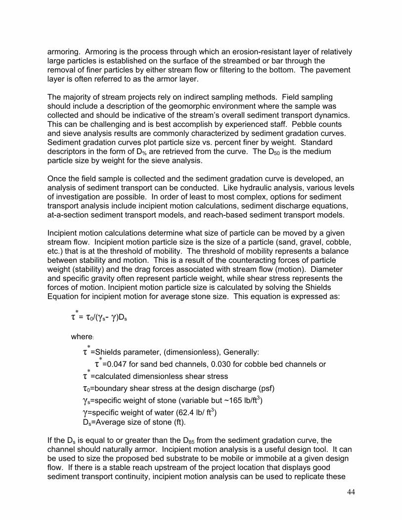
armoring. Armoring is the process through which an erosion-resistant layer of relatively large particles is established on the surface of the streambed or bar through the removal of finer particles by either stream flow or filtering to the bottom. The pavement layer is often referred to as the armor layer.
The majority of stream projects rely on indirect sampling methods. Field sampling should include a description of the geomorphic environment where the sample was collected and should be indicative of the stream’s overall sediment transport dynamics. This can be challenging and is best accomplish by experienced staff. Pebble counts and sieve analysis results are commonly characterized by sediment gradation curves. Sediment gradation curves plot particle size vs. percent finer by weight. Standard descriptors in the form of D% are retrieved from the curve. The D50 is the medium particle size by weight for the sieve analysis.
Once the field sample is collected and the sediment gradation curve is developed, an analysis of sediment transport can be conducted. Like hydraulic analysis, various levels of investigation are possible. In order of least to most complex, options for sediment transport analysis include incipient motion calculations, sediment discharge equations, at-a-section sediment transport models, and reach-based sediment transport models.
Incipient motion calculations determine what size of particle can be moved by a given stream flow. Incipient motion particle size is the size of a particle (sand, gravel, cobble, etc.) that is at the threshold of mobility. The threshold of mobility represents a balance between stability and motion. This is a result of the counteracting forces of particle weight (stability) and the drag forces associated with stream flow (motion). Diameter and specific gravity often represent particle weight, while shear stress represents the forces of motion. Incipient motion particle size is calculated by solving the Shields Equation for incipient motion for average stone size. This equation is expressed as:
*= 0/( s- )Ds
where:*=Shields parameter, (dimensionless), Generally:
*=0.047 for sand bed channels, 0.030 for cobble bed channels or *=calculated dimensionless shear stress 0=boundary shear stress at the design discharge (psf) s=specific weight of stone (variable but ~165 lb/ft3)=specific weight of water (62.4 lb/ ft3)
Ds=Average size of stone (ft).
If the Ds is equal to or greater than the D85 from the sediment gradation curve, the channel should naturally armor. Incipient motion analysis is a useful design tool. It can be used to size the proposed bed substrate to be mobile or immobile at a given design flow. If there is a stable reach upstream of the project location that displays good sediment transport continuity, incipient motion analysis can be used to replicate these
44

transport conditions in the design reach. Iterations in channel size, shape and slope can be made to meet estimated transport requirements based on incipient motion analysis and shear stress.
Sediment transport equations are used to estimate the volume and size of material that can potentially be moved by the stream. The potential transport capacity of the stream can be evaluated at design flow conditions. Equations have been developed for bed load, suspended load, and total load, and are dependent on particle size and flow hydraulics. They are typically developed as regressional fits to measured flume or field data, and are often based on steady uniform flow. Many equations were developed for sand bed streams and an appropriate equation must be selected for the project stream type. The use of sediment transport equations can be greatly improved by calibrating them with measured field data.
Several sources for sediment transport equations are included, following this section. Sediment transport equations should be used with a degree of caution and require a considerable amount of training and experience. Often sediment discharge rates (Qs)are correlated to a discrete flow discharge event (Qw). This is repeated for a number of discharge events to create a sediment rating curve over a range of anticipated flow conditions.
Sediment transport models couple flow hydrology with sediment transport equations. Development of a sediment transport model requires significant effort, interpretation, and manipulation. This usually requires an experienced modeler and a licensed professional with considerable experience in hydraulics and sediment transport. Sediment transport models are either at-a-section or reach based.
At-a-section-models are used to estimate sediment transport conditions using the Manning’s equation at a single cross-section. The Stable Channels in Alluvial Material (SAM) model developed by the U.S. Army Corps of Engineers is an example of an at-a-section model. A cross-section must be chosen that is representative of overall reach conditions.
Reach based models use a one-, two-, or three- dimensional hydraulic model with sediment transport equations to provide information on the volume of sediment transported across a series of cross-sections. Information provided by a reach based model can include the amount of sediment transported, location of aggradational and degradational processes, the volumes associated with these processes, and the time period over which these processes occur. One-dimensional models include HEC-6 and the sediment modeling component of HEC-RAS. This component was added to HEC-RAS shortly before the publication of this guide and may become the industry standard in the near future. Two-dimensional models include GSTARS, SED-2D, and FLO-2D.
Reach based sediment transport models should be used when sediment transport is critical to the design and the level of detail required justifies the time and expense of model development. Sediment transport models are used primarily to determine the volume of sediment transported during a single flow event, the average annual
45

46
sediment load from a number of return interval events, and the average annual sediment load from flow duration curves.
Selected References
Bunte, K. and S.R. Abte. 2001. Sampling Surface and Subsurface Particle SizeDistributions in Wadable Gravel- and Cobble-Bed Streams For Analyses In Sediment Transport, Hydraulics, and Streambed Monitoring. USDA ForestService, Rocky Mountain Research Station. Fort Collins, CO. http://www.fs.fed.us/rm/pubs/rmrs_gtr74.html
Leopold, L.B., M.G. Wolman and J.P. Miller. 1995. Fluvial Processes in Geomorphology. Chapter 6. Dover Publishers. Mineola, NY.
Soar, P.J. and C.R. Thorne. 2001. Channel Restoration Design For MeanderingRivers. US Army Corps of Engineers Engineering Research and Development Center, Coastal and Hydraulics Laboratory. Vicksburg, MS.
47
2.10 Design Strategies for Incised Streams
The consequences of past efforts to control rivers through channelization, dredging, straightening, and confinement are incision or degradation of the channel bed. An incised channel becomes disconnected from its original floodplain and cannot dissipate its storm flows. Because the storm flows are confined to the incised channel, shear stress and velocities increase, resulting in bank and bed erosion, channel widening, and habitat degradation.
Incised channels are primary candidates for in-stream projects due to high bed and bank erosion rates and poor habitat. Reconnecting the incised channel to its original floodplain or creating a new floodplain is a primary goal in restoring incised channels.Re-connecting the channel to a functional floodplain relieves the high shear stresses and bank erosion.
An incised stream has a bank height ratio greater than 1.0 ft/ft, meaning that the bankfull stage is at or lower than either of the banks. Severely incised streams with bank height ratios greater than 1.6 ft/ft are typically very unstable. Slightly to moderately incised streams with bank height ratios between 1.1 and 1.6 may be stable, however, they can become unstable due to changes in watershed or riparian buffer condition.
The goal of re-connecting an incised stream to its historical floodplain can result in reestablishment of many lost floodplain functions. Restoring an incised stream can re-establish surface and groundwater hydrology to floodplain wetlands. The re-establishment of both the floodplain and the stream also restores an important habitat for aquatic organisms. However, the goal of re-connecting an incised stream to its historical floodplain may not always be an appropriate one. In many watersheds, the floodplains have become occupied by land uses that are not compatible with restored floodplain hydrology. Particularly in urban watersheds, increased flooding in the historical floodplain may conflict with utilities, road crossing, buildings, and stormwatermanagement basins.
Rosgen (1997) proposed four basic options or “priorities” for addressing the restoration of incised streams. These options are:
Option 1-Establish New Channel at Historical Floodplain Elevation
This option creates a new meandering channel on a new alignment at its original floodplain elevation. The abandoned incised channel is either filled or converted into wetland ponds. This option is the most effective at restoring historical floodplain functions, including wetland habitat. This option is usually only available in rural watersheds where there is a large amount of floodplain that is not occupied by structures or utilities. Since the new channel can be built in the dry, difficulties of managing stream flow are minimized. Since this option constructs only a new channel and not a new floodplain, it will result in less excavation than an Option 2 project. If an

48
Option 1 project would require clearing a forested floodplain, the applicability of an Option 2 or 3 approach should be considered.
Option 2- Create New Floodplain and Stream Pattern Below the Historical Floodplain Elevation but Above Current Stream Elevation
Option 2 creates a new, meandering channel with a new floodplain built at an elevation lower than the original floodplain elevation. This option does not reconnect to the original floodplain lost due to incision, but creates a new floodplain at a lower elevation.The new channel typically follows the general alignment of the incised channel, but with a stable plan-form. The excavation of a new floodplain results in significant excavation that increases disposal requirements. In order to reduce floodplain excavation, grade controls can be used to raise the bed. Option 2 projects are often a combination of lowering the floodplain and raising the bed elevation to balance earthwork. Because the new channel may cross the incised channel several times, construction sequencing and streamflow management become more critical than in Option 1 projects. This approach requires considerable open land to allow for the excavation of the new floodplain and changes to the stream plan-form.
Option 3 –Change Channel Type along Existing Channel
This option stabilizes the incised channel by converting to a more stable stream type.Typically, Option 3 projects include using grade controls to stop incision and dissipate stream energy, adjusting cross-section, reducing bank slope, and creating a new floodplain bench, but minimally adjusting the plan-form. The plan-form of the stream is not significantly changed due to constraints and conflicts, keeping the new channel on the same alignment as the incised channel. A small floodplain bench is often constructed into one or both of the banks, but not a full floodplain. The profile and cross-section may be altered to improve stream functions. Since a full floodplain is not constructed and the stream is still incised, shear stresses are handled by using more in-stream structures to protect the bed and bank. For example, relatively steep, unstable channels (Rosgen G type) can be converted to steep but stable channels with the use of step/pool structures (Rosgen B type). However, there are many low gradient incised channels in the mid-Atlantic which are not good candidates for Option 3 treatment because they are no longer actively incising. This option may be used in relatively short sections to allow for the transition between two channel sections with significant elevation differences (i.e. headcut).

49
Option 4- Stabilize Channel In Place
This option stabilizes incised channels at the existing bed elevation and along the existing planform alignment. An Option 4 project should only be proposed where Options 1-3 are not feasible. Option 4 does not provide a re-connection to a floodplain (i.e. still incised), nor re-establish proper planform, which means there is no reduction in channel shear stresses. Since the channel is still incised, the stabilization methods employed must be able to resist high shear stresses and velocities during large storm flows. However, Option 4 projects can address bank erosion, vertical degradation, and habitat issues.
This approach is the traditional armor in-place approach used for decades to address incised channels and bank erosion. Historically, hard methods such as gabions, concrete, and riprap have been used extensively to stabilize incised channels in place.However, designers should consider if “softer” methods might be utilized where shear stress and velocities will permit it. In urban streams where streams are incised, plan-form adjustments are not feasible, and storm flows are very severe, Option 4 may be the only choice available to a designer to address bank and bed erosion.
In many Option 4 projects, banks are stabilized with combinations of rock and bioengineering. The channel bed can be stabilized with strategically placed grade controls instead of lining the entire bed with concrete blocks, rock or other hard structures. By strategically providing grade control and stabilizing banks, the stability of the channel can be greatly improved, resulting in reduced in-stream erosion.
Selected References
Rosgen, D.L. 1997. A Geomorphical Approach To Restoration Of Incised Rivers. In Proceedings of the Conference on Management of Landscapes Disturbed by Channel Incision.
50
2.11 Aquatic Habitat and Fish Passage Considerations
The majority of the aquatic habitat within a stream channel occurs below the normal baseflow elevation. In rural streams where baseflow may be abundant, special design efforts may not be required to ensure that a sufficient area of aquatic habitat is present. However, in urban watersheds, the baseflow is substantially reduced compared to the bankfull flows. Special design efforts are required to concentrate the baseflow into an “aquatic” channel.
Historically, numerous structures have been used to specifically improve fish habitat in streams, particularly for gamefish. While this guide does not address structures specifically for habitat creation, many of the treatments and structures included in this guide will improve aquatic habitat. If habitat creation is a major goal of a stream channel design, the following should be considered:
Toe Treatments – Most toe treatments using rock provide minimal aquatic habitat.However, cedar tree revetments and rootwads provide near bank cover, which tends to attract and concentrate fish. Toe treatments can be combined in ways that improve habitat, such as incorporating rootwads into rock toe treatments or into a live cribwall.
Scour Holes – Grade control structures and deflectors create mid-channel scour holes for pool habitat. Rootwads also provide near bank scour holes, as well as cover.
Bioengineering – A major benefit of bioengineered bank treatments is that the plant growth along the banks provides shade, cover, and a source of leaf litter to the stream. Particularly where vegetation cover was absent prior to restoration, bioengineering can make a marked improvement in near bank riparian buffer conditions resulting in improved aquatic habitat. (For further Riparian Buffer information, visit the Virginia Department of Forestry’s website at http://www.vdof.org/rfb/riparian/rwg/riphome.htm.)
Large Woody Debris – Large woody debris plays a key role in providing habitat in a wide range of streams. In sandy streams, large woody debris may be the only stable substrates upon which benthic macroinvertibrates can colonize. In pools, debris jams provide structure and cover from predators. In steep streams, fallen large woody debris is a primary creator of step/pool morphology. Tree falls act to capture bedload and create the steps between pools. Log drop structures, log vanes, and rootwad revetments are structural attempts to mimic naturally occurring large woody debris.Large woody debris can be incorporated into many practices, including vanes, cross vanes, and J-hook vanes.
Aquatic Channel – In urban streams, the reduced amount of baseflow can limit the amount of aquatic habitat that a channel can support. Designers should concentrate the baseflow into a narrower “low flow” or “aquatic habitat” channel within the large bankfull channel. Concentrating the water into the aquatic channel increases aeration, reduces stream warming and temperatures, reduces siltation of pools, and improves overall aquatic habitat. Techniques such as sills, deflectors, and vanes can help concentrate base flows.

51
Fish Passage – During most of the 1990s, stream restoration was implemented without consideration of fish passage. It was assumed that if the channel design mimicked a natural channel form, then fish would be able to pass through the restoration section. However, many of the typical grade control structures employed may block fish passage. This appears particularly true on small streams and in urban watersheds with low base flows. Designers should evaluate fish passage as part of the design effort, particularly if there is the possibility of anadromous fish moving through the design channel.
Selected References
Rosgen, D.L. 1996. Applied River Morphology. Wildland Hydrology. PagosaSprings, CO.
Fischenich, J. C. 2003. Effects of Riprap and Riparian Ecosystems. EDRC/EL TR-03-4,US Army Engineer Research and Development Center, Vicksburg, MS.

53
CHAPTER 3: COSTS

55
3.1 Costs Introduction
Information about costs for in-stream projects is provided in this chapter. The information should be used for planning and comparative purposes only, and may vary significantly based on local conditions and constraints. The information is based on projects that have been completed in the mid-Atlantic area as of 2002. As more projects are completed around the state, and more detailed data is collected about costs, this chapter will be updated.
Total costs for in-stream projects can be divided into four broad categories:
• Assessment and Design
• Construction
• Construction Inspection and Maintenance
• Post-Construction Monitoring
Determining total project costs of public projects is often difficult because design,construction and monitoring are often separate contracts. Other costs, such as property acquisition, site selection and maintenance are very rarely reported. The linear footage is often not reported, so calculating costs on a per foot basis becomes difficult. The North Carolina Wetlands Restoration Program has reported total costs for three rural and two urban projects that have been completed which are summarized below: (North Carolina costs are presented due to a relative absence of information for costs in the Commonwealth of Virginia.)
Phases Rural Cost (L/F) Suburban-Urban Cost (L/F)
Range Average Range Average
Design $15-31 $22 $21-56 $32Construction $50-65 $58 $77-142 $109
ConstructionInspection/Management
$5-16 $11 $5-14 $12
Total Costs $106 $218Source: A preliminary Analysis of Stream Restoration Costs in the North Carolina Wetlands Restoration Program. Total costs includes acquisition and monitoring.

56
3.2 Assessment and Design Costs
Every in-stream project will require some level of assessment and design. Projects in rural watersheds may not require extensive planning and design. Projects in urban watersheds may require very extensive and expensive assessments and designs. If sufficient funds to properly assess and design a project are not available, the success of the project may be limited.
The assessment and design of in-stream projects often costs 15-30% of the construction costs. This cost is higher than traditional engineering design, which averages around 10-20% of construction costs. The higher costs reflect the complexity of designing a channel that functions like a natural stream instead of a trapezoid canal.Design costs can be covered by trained in-house staff or qualified outside contractors.
Assessment and design costs cover a wide range of work. Depending on the complexity of the project, a stream design project may contain any of the following components:
• Geomorphic Assessments and Stream Classification
• Reference Sites Location and Assessment
• Gauge Station Data Development
• Site Surveys
• Hydrologic and Hydraulic Modeling
• Sediment Transport Assessment and Modeling
• Conceptual through Final Design Development, including plans and specifications
• Construction Costs Estimates
• Environmental Permit Development and Coordination.
Numerous factors control the cost of planning and designing a project. Factors that affect costs are:
• Urban watersheds – Urban watersheds typically have more complex hydrology, more constraints, and more landowners to deal with. Urbandesigns typically require more robust analytical design efforts than rural watersheds.
• Stream Size - Larger rivers have a higher risk of failure during storm events. This risk may require additional design efforts.
• Project Length – There is an economy of scale to design. Shorter projects may have a higher price per linear foot.
• Relocation of Utilities – The presence of utilities that have to be relocated adds to the level of engineering needed for a project.

57
• Severity of the Channel Instability – Dealing with plan form adjustments or deeply incised streams is more complex than minor incision or bank stabilization. The more complicated the solution to restoring the channel, the greater the design costs.
• Type of Construction Contract – If a project is a design-build contract, then designs may be less detailed since the designer will also build the project. In a typical design/bid/build scenario, the designer must provide a higher level of detail to protect the project owner from contractor claims. Typically a design-build contract can save approximately 25 to 30% on the design costs.
Design costs for in-stream projects vary widely depending on the intricacy of the design and the availability of information or data needs. A typical fluvial geomorphic design for an urban stream, including modeling hydrology and addressing sediment transport, ranges from $30 to $75 per linear foot.
3.3 Construction Costs
There are different methods to determine construction costs, depending on the stage of design (concept versus final design), and how the project is going to be contracted. If state forces are constructing the project with state materials and equipment, then a time and materials estimate would be appropriate. If the project is in the planning stages, without details about types of structures or bank treatments, then a cost per linear foot approach may be the most reasonable. If the project is in the preliminary to final design stage, then an engineer’s estimate based on unit costs would be appropriate.
Construction costs may be reduced by salvaging native materials from local sources or by the use of donated equipment or volunteer labor. Some examples of salvaging native materials include:
• Rootwads from land clearing, or flood debris.
• Rock from local construction projects.
• Plant materials from clearing.
• Riffle substrate from an abandoned channel.

58
Planning Level Estimates - Construction Costs Per Linear Foot
The size of the stream, the condition of its watershed, and the severity of channel instability are generally known at the planning level. Using this information, a planning level cost estimate can be developed based on the linear feet of channel requiring restoration. Table 3.1 provides some typical examples of per linear foot costs. These costs are very broad and are provided for comparison purposes only. Table 3.2 provides examples of projects with different characteristics and the cost per linear foot for construction.
There are numerous factors that affect the cost of constructing a project. Factors that affect costs include:
• Construction Plans and Specifications–Clear, concise and accurate plans
reduce construction costs.
• Stream Size - Larger streams require greater quantities of earthwork, stone and other materials, and more stream flow maintenance.
• Project Length – There is an economy of scale to construction, with longer projects resulting in lower per foot costs than shorter projects.
• Urban watersheds – Urban watersheds typically have more constraints toconstruction access, require outfall repairs, and often involve pedestrian considerations such as foot bridges or trails. Large plant material is often required for a more mature landscape than in rural watersheds.
• Relocation of Utilities – The presence of utilities that have to be relocated adds an additional level of construction cost to a project.
• Easement purchase/negotiation – Purchase of easements on private property can increase costs or delay construction activities. Access easements are often required across private property during construction.
• Weather – Excessive rainfall or snowfall can delay projects and add costs to construction.

59
TABLE 3.1TYPICAL STREAM CHANNEL PROJECT CHARACTERISTICS
AND CONSTRUCTION COSTS PER LINEAR FOOT(assuming a second –third order stream)
Typical ProjectsPer Linear Foot
Construction Costs Comments
Rural watershed requiring fencing and riparian buffers, and cattle
watering$25-75
Cost can be lower if implemented by
volunteers or agency staff
Rural watershed requiring a priority one or two relocation (construct
new floodplain and channel)$50-100
No constraints to constructing new channel, readily
available materials nearby
Suburban/Urban stream requiring bank stabilization, grade structures
with some utility and similar constraints
$90-250
Stabilization in-place,and limited ability to
salvage local materials increases costs
Urban watershed, highly confined channel stabilized in-place,
requiring utility relocations, outfall repairs, with many constraints
$250-400Urban constraints, utilities and outfalls result in high costs
Source: Costs were derived from a review of a range of projects, but individual project costs can be highly variable. Construction costs include labor, material, equipment and installation, but excludes design costs.

60
TABLE 3.2SUMMARY OF SELECTED VIRGINIA
In-STREAM PROJECT CONSTRUCTION COSTS
Project Description Land Use ConstructionCost
Length (ft) Cost per Linear Foot
Cheswick Park (2000)Henrico County Virginia
Step/pool structure over exposed sewers, bank grading and matting Suburban/
Commercial $40,000 400 100
North Fork-AccotinkCreek-Mosby(2001)City of Fairfax,Virginia
Restoration incl. grading of streambanks and some realignment followed by native plant installation
and rock control structuresMixed, urban $370,000 3,839 96
North Fork-AccotinkCreek-Ranger(2002) City of Fairfax,Virginia
Restoration incl. grading of streambanks and some realignment followed by native plant installation
and rock control structuresMixed, urban $388,000 3600 107
Kingstowne Creek (1999) Fairfax County, Virginia
Planform, profile and cross section restoration, with natural cobble
substrateUrban $160,000 1,100 $145
Moores Creek(1999) Charlottesville, Virginia
Channel planform adjusted with rock and rootwads on meanders, with
several grade control structures in each meander
Mixed, urban, suburban, rural $250,000 1200 208
Meadow Creek (2000)Albemarle County, Virginia
Bank reconstruction and stabilization, rock and matting Urban $94,000 300 315
Doyles River (1998)Albemarle County, Virginia
Bank reconstruction and stabilization, rock toe, branch layering (all salvaged), some
meander work
Rural $17,000 250 70

61
Engineers Construction Estimates -- Per Unit Costs
Once a project has moved to preliminary or final design, estimates of the quantity of items in the plans can be made. A construction cost estimate may be based on the quantity of each item in the design and assumed per unit costs.
Project owners are sometimes required to bid projects based on a per unit cost. A list of quantities needed is produced, and the contractors bid a specific cost for each item (i.e. per rock vane, shrub, etc.). The critical steps in a per unit cost estimate are to identify all labor or materials required for the project. Once labor and materials are identified, an accurate per unit cost for each item should be developed.
Table 3.3 presents estimated per unit costs for each of the practices included in this edition of the guide. Table 3.4 presents the typical incidental costs that must also be included in an engineers construction estimate.
Unit costs vary depending on quantity and availability of materials. Costs for structures that require logs (log vane, log drops, and rootwads) are highest where material cannot be salvaged on-site during clearing and grubbing operations. Cost for rock is highest when haul distances are greatest. Substrate material (cobble and gravel), bioengineering materials, plants, and sod mats can sometimes be salvaged onsite.
The cost of stone structures (step/pools, vanes, cross vanes, stacked stone walls, etc.) can be based on the linear foot of structure, cubic yard of rock or ton of rock in each structure or a lump-sum cost for each structure. As channel size impacts structure size, tons or cubic yard may be a better method of costing than a cost per each structure.For each structure, the designer can calculate the volume and weight of rock. Typically, rock weighs 1.5-1.9 tons per cubic yard. An alternative method is cost based on linear footage of structure. This approach encourages contractors to use the largest possible stones since it requires less installation time per linear foot to place large stone compared to small stone. Costs based on tons or cubic yards tend to encourage use of smaller stones, which are easier to obtain and transport.
The cost per linear foot can be used for selected practices such as coir fiber logs or rock toe revetments. However, those structures that have a vertical dimension (stacked stone walls, live crib wall, etc.) should not be estimated per linear footage. A more suitable pricing would be per square foot of wall face, or volume of material per foot.

62
Other costs that must be accounted for include:
• Mobilization (10% of total unit costs)
• Survey (5% of total unit costs)
• Access Road (Often needed, but costs are highly variable with each site)
• Maintenance of Stream Flow (Often highly variable, and can be extremely costly on large projects)
Stream techniques are new to many contractors and bids may be high. The high bids protect the contractor from unexpected problems associated with unfamiliar practices and the risk of working near and in water. As contractors become more familiar with construction practices, the unit costs will become more uniform and predictable.
Time and Materials CostsFederal, state and local governments may have the staff and equipment to construct stream projects. For these projects, the labor and materials costs can be estimatedbased on the type of structures or bank treatments being installed. Unlike design or construction contracts put out to bid, the costs of time and material projects are not typically recorded or tracked in any systematic fashion by the agencies. Time and material costs are not reported in this handbook because of the lack of historical cost information.
Typically, the costs to an agency of constructing a project with in-house staff, material and equipment is often less than if the project was put out to bid. However, many hidden costs are often not accounted for, such as benefits for staff or liability risks.
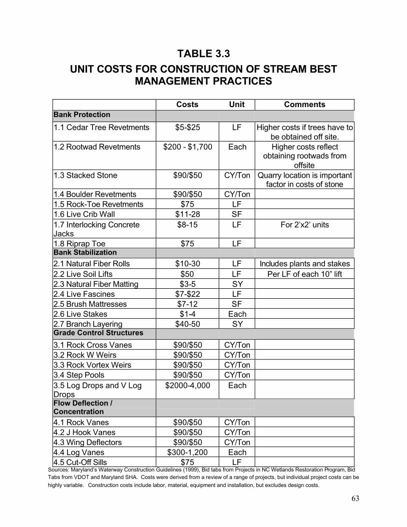
63
TABLE 3.3UNIT COSTS FOR CONSTRUCTION OF STREAM BEST
MANAGEMENT PRACTICES
Costs Unit CommentsBank Protection 1.1 Cedar Tree Revetments $5-$25 LF Higher costs if trees have to
be obtained off site. 1.2 Rootwad Revetments $200 - $1,700 Each Higher costs reflect
obtaining rootwads from offsite
1.3 Stacked Stone $90/$50 CY/Ton Quarry location is important factor in costs of stone
1.4 Boulder Revetments $90/$50 CY/Ton 1.5 Rock-Toe Revetments $75 LF 1.6 Live Crib Wall $11-28 SF 1.7 Interlocking Concrete Jacks
$8-15 LF For 2’x2’ units
1.8 Riprap Toe $75 LF Bank Stabilization 2.1 Natural Fiber Rolls $10-30 LF Includes plants and stakes2.2 Live Soil Lifts $50 LF Per LF of each 10” lift2.3 Natural Fiber Matting $3-5 SY 2.4 Live Fascines $7-$22 LF 2.5 Brush Mattresses $7-12 SF 2.6 Live Stakes $1-4 Each 2.7 Branch Layering $40-50 SY Grade Control Structures 3.1 Rock Cross Vanes $90/$50 CY/Ton 3.2 Rock W Weirs $90/$50 CY/Ton 3.3 Rock Vortex Weirs $90/$50 CY/Ton 3.4 Step Pools $90/$50 CY/Ton 3.5 Log Drops and V Log Drops
$2000-4,000 Each
Flow Deflection / Concentration
4.1 Rock Vanes $90/$50 CY/Ton 4.2 J Hook Vanes $90/$50 CY/Ton 4.3 Wing Deflectors $90/$50 CY/Ton 4.4 Log Vanes $300-1,200 Each 4.5 Cut-Off Sills $75 LF
Sources: Maryland’s Waterway Construction Guidelines (1999), Bid tabs from Projects in NC Wetlands Restoration Program, Bid Tabs from VDOT and Maryland SHA. Costs were derived from a review of a range of projects, but individual project costs can be highly variable. Construction costs include labor, material, equipment and installation, but excludes design costs.

64
TABLE 3.4UNIT COSTS FOR INCIDENTAL CONSTRUCTION ITEMS
Item Costs UnitsConstruction Office $750 Month
Excavation $3-20 CYClearing and Grubbing
(Woodland)$5,000-10,000
Acre
Silt Fence $2 LFBlaze Orange Fence $2 LF
Coir Erosion Control Matting $5 SYTemporary Construction Entrance $1,500-
2,000Each
Temporary Stream Crossing / Ford $2,000-5,000
Each
Permanent Seeding $1,000-$2,000
Ac
Temporary Seeding $100-125 AcHerbaceous Plugs $1.50 Each
Containerized Shrubs (12-24”) $12 EachTubling Shrubs $3 Each
Bare Root Woody $1.5 EachContainerized Trees (3-4’) $20 Each
Ball and Burlap Trees $300 EachLime $200 Ton
2 “ Topsoil (salvaged) $2,500 Ac6 “ Topsoil (Furnished) $5,000 Ac
Source: Costs of Incidental Items drawn from bid tabulations from a variety of projects by VDOT, MSHA, and NC Wetlands Restoration Program. Construction costs include labor, material, equipment and installation, but excludes design costs.

65
3.4 Construction Inspection and Maintenance Costs
In-stream projects have the potential to face difficulties during construction such as:• Contractor’s lack of familiarity with stream construction.
• Need to modify design in the field due to unforeseen conditions such as buried utilities and unsuitable conditions (soils, hydrology).
• Potential for storm events to disrupt work.
• Time of Year restrictions – Planting in dormant season, grading in low flow periods, permit restrictions during spawning seasons.
• Difficulty in obtaining correct materials (properly sized and shaped rock, live stakes in dormant condition, etc.)
Inspectors knowledgeable with stream techniques and methods are critical to the success of a project. If project owners are not familiar with stream construction, they should contract with the designer or third party inspectors to provide construction inspection services. Inspection costs are typically $10-15 per linear foot, or 10-30% of the construction costs depending on the frequency of inspection.
Stream projects may require repair and maintenance within the first 1-2 years. Storm events are more likely to cause erosion or to displace bank protection until the vegetation on the site is mature and able to hold the bank and floodplain soils in place.Typical activities which should be anticipated include replanting of dead plant materials, reseeding of bare areas, controlling invasive plants, modifying grade control structures, fencing repair, etc. In addition, the fine-tuning of a percentage (10-20%) of the step/pools or cross vanes to function more efficiently may be needed. During the first 1-2 years, this follow-up maintenance and inspection is critical to the long-term success of the site. You should anticipate expending up to 10-20% of the original construction costs on maintenance. The amount actually expended is often dependent on the number of significant storm events and other weather factors. Maintenance should be separate from the construction contract or a separate line item in the construction document so that owners do not pay for repairs if they are not required.

66
3.5 Monitoring Costs
Long-term monitoring of the site for regulatory purposes is an additional cost that will become more common as the regulatory program in Virginia places more requirements on projects for post-construction monitoring. The monitoring costs will vary based on type of monitoring and frequency of site visits required by the agencies and the size of the project.
Monitoring efforts may include physical measurement of cross-sections and longitudinal profiles as well as assessments of biological communities. Channel stability and erosional patterns can be assessed utilizing pebble counts, bar samples, and bank and bed pins. In addition, it can also be beneficial to perform as-built surveys or aerial photographs, on a yearly basis, to provide a graphical representation of changes to the profile, plan form and cross-section of both the channel and floodplain.
Costs for monitoring will become more defined as the regulatory agencies develop consistent guidance concerning post-construction monitoring. In North Carolina, where post-construction monitoring regulations are established, post-construction monitoring costs approximately $7,500-$10,000 per year.
Acknowledgement
A number of professionals provided information and input into the development of this chapter including:
Asad Rouhi, Northern Virginia Soil and Water Conservation DistrictJohn Denisten, Maryland State Highway AdministrationAdrian Fremont, City of Fairfax. Dave Hirschmen, Albemarle CountySuzanne Klimek, North Carolina Wetlands Restoration Program

67
CHAPTER 4:BEST MANAGEMENT PRACTICES

69
Introduction
This chapter describes a number of physical practices and structures used in stream design projects. While Chapter Two describes approaches to designing a stable dimension, pattern, and profile, this chapter describes practices that are used to ensure the stability of the streambed and banks. The majority of the techniques try to replicate natural stream conditions by using vegetation, rock, and natural materials. The focus is on using “softer” engineering techniques than those traditionally utilized by civil engineers in channelization, flood control, and drainage improvement projects. However, the specific techniques employed must be able to withstand the erosive forces associated with stream flows for different storm events.
The techniques are presented as separate practices. In reality, it is common to combine techniques into integrated treatments to ensure the stability of the bed and banks. The possible combinations are almost endless, and each project should be evaluated individually. The drawings presented in this guide are typical details and should be revised to reflect project conditions. Stream designers are encouraged to create specific bed and bank treatments for every project.
This chapter does not present a comprehensive list of every technique ever used in a stream project. Instead, it pulls from a number of technical sources and the collective experience of stream practitioners to present a synthesis of the major techniques currently used in the design of dynamically stable streams. The designer should not be discouraged to employ other measures (such as habitat enhancement structures) as she or he sees fit on a project-by-project basis.
Section One of this chapter presents bank protection guidelines. As mentioned in Chapter 2, shear stresses are greater in the lower third of the streambank. In addition, toe scour can undermine the streambank and result in bank failure. A scour depth analysis should always be conducted for toe treatment to ensure that they are not undermined during higher flow events. Refer to Section 2.7 for scour analysis references.
It should be noted that Standard and Specification 3.19: Riprap in the Virginia Erosion and Sediment Control Handbook can be used as a streambank treatment. This method uses rock to protect the entire bank, not just the lower portion. Its use should be reserved for those situations where site and economic constraints prevent the use of other Section One practices.
Section Two of this chapter describes bank stabilization guidelines. These practices are commonly referred to as bioengineering techniques. They rely heavily on the use of dormant woody vegetation and degradable manufactured natural fiber products. Techniques from Section Two can be used for the upper two-thirds of the bank as an integrated bank treatment when a more rigid technique from Section One is required for the lower third and toe of the streambank. They can also be used for the lower third of the bank when velocities, shear stresses, and scour potential are relatively low. Where

70
conditions allow, the use of bank stabilization techniques is preferred over more rigid, structural stream protection techniques.
Section Three moves from the streambank to the streambed. Streams that are vertically unstable and/or incised may require grade control. Grade control can be used to stop the upstream migration of a head cut, to raise the elevation of an incised channel, or to tie a new channel into an existing channel. Some grade control structures can also be used to train flow away from the banks and into the channel.When a project includes grading a completely new channel, grade control structures help to insure channel stability until the channel stabilizes. The first four practices included in this section are rock grade control structures and are most appropriate for medium to large streams with predominately cobble and gravel streambeds. The log structures detailed in Section 3.5 are well-suited for smaller, steeper systems. Rock structures can be hard to build in smaller streams and have a tendency to subside in sand and clay/silt dominated systems.
Section Four techniques are used to redirect or concentrate stream flow. Rock, J-hook,and log vanes are used to direct shear stresses and velocities away from the streambank towards the thalweg. The choice of rock or wood is driven by the same conditions described above. Wing deflectors and cut-off sills are used for over-widenedstreams or nested channels when baseflow is included as a design discharge. These structures allow for the concentration and conveyance of lower flows without losing channel capacity for the transportation of larger discharges.
Section Five describes several in-stream construction techniques that are specific to stream channel projects and are not described in the Virginia Erosion and Sediment Control Handbook. These techniques are extremely useful in maintaining stream flow during construction. They are typically used when construction must occur in the active stream channel and dry conditions are required for grading activities and for the installation of structures. While this guide provides information on many best management practices for stream stabilization and restoration activities, there are many other practices and information available which also could be used. Readers must consult other references and resources in order to successfully complete a stream channel project. In addition, the use of this guide and the practices described herein does not guarantee project approval by the regulatory agencies, as site-specific considerations often play a significant role.

71
SECTION 1BANK PROTECTION GUIDELINES
PRACTICE 1.1. CEDAR TREE REVETMENTS PRACTICE 1.2. ROOTWAD REVETMENTS
PRACTICE 1.3. STACKED STONE
PRACTICE 1.4. BOULDER REVETMENTS PRACTICE 1.5. ROCK-TOE REVETMENTS
PRACTICE 1.6. LIVE CRIB WALL PRACTICE 1.7. INTERLOCKING CONCRETE JACKS
References:
North Carolina State University Cooperative Extension. River Course Fact Sheet Number 4. Using Root Wads and Rock Vanes for Streambank Stabilization.
Maryland Department of the Environment. 1999. Waterway Construction Guidelines.
Washington State Aquatic Habitat Guidelines Program. 2003. Integrated Streambank Protection Guidelines.
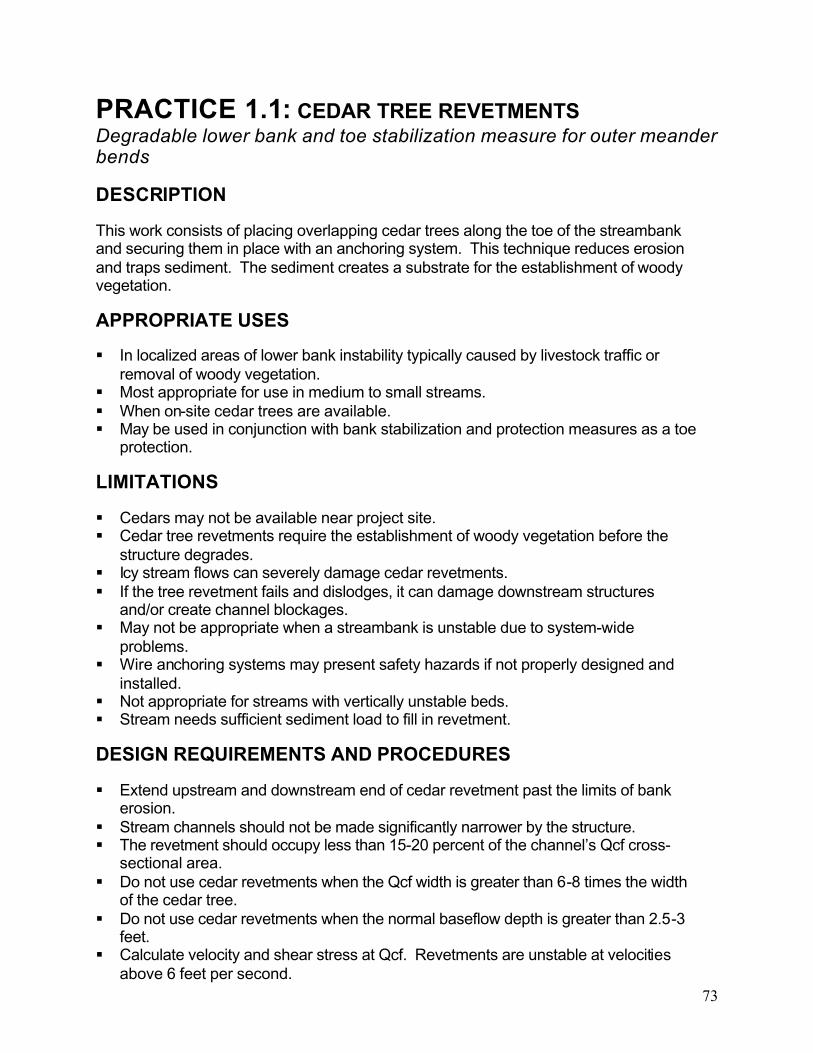
73
PRACTICE 1.1: CEDAR TREE REVETMENTSDegradable lower bank and toe stabilization measure for outer meander bends
DESCRIPTION
This work consists of placing overlapping cedar trees along the toe of the streambank and securing them in place with an anchoring system. This technique reduces erosion and traps sediment. The sediment creates a substrate for the establishment of woody vegetation.
APPROPRIATE USES
In localized areas of lower bank instability typically caused by livestock traffic or removal of woody vegetation.
Most appropriate for use in medium to small streams. When on-site cedar trees are available. May be used in conjunction with bank stabilization and protection measures as a toe
protection.
LIMITATIONS
Cedars may not be available near project site. Cedar tree revetments require the establishment of woody vegetation before the
structure degrades. Icy stream flows can severely damage cedar revetments. If the tree revetment fails and dislodges, it can damage downstream structures
and/or create channel blockages. May not be appropriate when a streambank is unstable due to system-wide
problems. Wire anchoring systems may present safety hazards if not properly designed and
installed. Not appropriate for streams with vertically unstable beds. Stream needs sufficient sediment load to fill in revetment.
DESIGN REQUIREMENTS AND PROCEDURES
Extend upstream and downstream end of cedar revetment past the limits of bank erosion.
Stream channels should not be made significantly narrower by the structure. The revetment should occupy less than 15-20 percent of the channel’s Qcf cross-
sectional area. Do not use cedar revetments when the Qcf width is greater than 6-8 times the width
of the cedar tree. Do not use cedar revetments when the normal baseflow depth is greater than 2.5-3
feet. Calculate velocity and shear stress at Qcf. Revetments are unstable at velocities
above 6 feet per second.

74
Maximum bank height for cedar tree revetments is 12 feet. The diameter of the tree’s crown should be about two-thirds the height of the eroding
bank.
MATERIAL SPECIFICATIONS
Revetment Trees: Trees should have numerous limbs and fine branches. Tree species other than cedar can be used if they are resistant to decay and have a similar growth form.
Anchors: Duckbill, arrowhead, disc, or fencepost anchors per manufacturers’ specifications made of a rust resistant metal material. Anchors should be sized to resist 1200 pound pullout force at a minimum.
Clamps: Rust resistant saddle clamps or figure 8 sleeves. Cable: 3/16 inch aircraft cable or equivalent.
CONSTRUCTION RECOMMENDATIONS
Late winter and early spring are usually the best times to build cedar revetments, since trees placed in early summer can dry out and lose their needles before being flooded.
A post-driver (manual or electric) is required to set the anchors. Each tree in the structure should be anchored at both ends at a point on the trunk
near the toe of the streambank. No large, single limbs should protrude into the channel. Trees should be harvested as close to time of installation as possible before they
become desiccated and prone to breaking. Sections of the tree trunk without limbs should be removed, as the limbs reduce
velocities and trap sediment to protect the bank.
INSTALLATION GUIDELINES
Using a tractor or similar equipment, stage trees on top of the streambank. Starting at a stable area of the streambank downstream from the eroded areas,
place the tree along the toe of the eroded streambank, with the top end pointed downstream.
Attach cable to the anchor and drive anchor into the streambank a minimum of 5 feet using a post driver. Drive an anchor and cable at the trunk end and the top end of the tree.
Secure the top end firmly against the toe of the bank and pull cable tight using tractor or equivalent. Tighten clamp.
Move next tree into place so it overlaps the butt end with the first tree. Overlap the second tree on top of the first tree so that there are no gaps between them. Use the cable placed into the bank at the butt of the first tree to secure the top end of the second tree, thereby securing both trees. Tighten and clamp as described above.
Drive an anchor and cable into the streambank for securing the butt of the second tree and the top end of the third tree.
Repeat the above two steps for all additional trees until a stable area of streambank upstream of the eroding bank is reached.

75
Place riprap at the upstream end of the cedar tree revetment to prevent scour and erosion.


77
PRACTICE 1.2: ROOTWAD REVETMENTSRigid lower bank and toe protection measure for outer meander bends
DESCRIPTION
A rootwad revetment consists of the lower trunk and root fan of a tree (rootwad), a footer log, and large boulders or graded riprap. Individual rootwads are placed in series along the outer meander bend in the lower portion of the streambank and provide immediate bank protection.
APPROPRIATE USES
In outer mender bends where a rigid protection strategy is needed that also has high habitat value.
When on-site materials are available for making rootwad revetment. Used as a component of an integrated bank treatment for rigid stabilization of the toe
and lower bank region. Used in combination with a vane device such as PRACTICE 4.1: Rock Vanes and
PRACTICE 4.2: J-Hook Vanes. Often used to repair streams after major floods, as trees are readily available.
LIMITATIONS
Site must be accessible to heavy equipment. Structures can degrade after 5-15 years. Long-term stability depends on
establishment of woody vegetation. Species selection can increase life of structure. Rootwads collect litter in urban areas and can cause public perception problems. Rootwad revetments can be very expensive if onsite materials are not available. Not well suited for smaller, headwater streams. May be undermined or flanked if the channel is still experiencing plan form or vertical
adjustments. Ensuring the upstream meander bend is stable minimizes risk of failure.
Not suitable for highly sandy banks (<15% silt and clay).
DESIGN REQUIREMENTS AND PROCEDURES
The bottom of the footer log and root fan must extend slightly below the design scourdepth.
Effective design hinges on determining a stable meander radius of curvature. Length of the rootwad trunk determined by anticipated scour behind the rootwad.
Size trunk so that 3/4 of its length remains embedded in bank at maximum anticipated scour.
Spacing and orientation of rootwads to flow is highly variable in practice and in the literature. Designer must ensure that velocity current is deflected away from the

78
streambank along the outer meander bend. Some suggestions and ranges are given below:
Spacing: Rootwads can be placed along the banks so the root fans overlap. This is sometimes called root wrap and provides the most complete bank protection. At a maximum, rootwads can be spaced at radius of curvature to top widths (Rc/W) of greater than 3.0. At less than 2.5, the rootwads no longer deflect flow. A general rule is that the rootwads should be spaced 3-4 times the length they extend past the bank. Orientation: Typically, the face of a single root fan is positioned at 90
degrees to the incoming flow, but can be rotated as much as 15 degrees toward the stream channel (away from the streambank). In root wrap, the orientation is parallel to the bank.
Thresholds and allowable stress guidelines have not been developed. A hydraulic analysis of near bank erosional forces can minimize risk.
Erosion most often occurs in unprotected or poorly compacted soil around roodwad.Design should address need for bank stability behind Rootwad.
If Qcf elevation provides less than 1.5 feet of cover over the trunk of the rootwad, the placement of bracing boulders on top of the rootwad will improve stability and counter buoyancy of rootwad.
MATERIAL SPECIFICATIONS
Rootwad: Lower portion of a preferably rot-resistant tree species consisting of a root fan and a trunk. The root fan shall have a diameter roughly equal to the vertical distance from the design scour depth to the Qcf elevation. Root fans shall have relatively few broken branches and be securely attached to the trunk. Trunks shall be relatively straight and free of breaks, and splits. Trunks shall be long enough so that 3/4 of their length is securely embedded in the bank at maximum scour. A minimum length of 10 feet and a maximum length of 20 feet are recommended.Trunks should have a minimum diameter of 12 inches.
Footer Logs: Minimum of 12-inch diameter log meeting the same specifications as the rootwad trunk above. Length is determined by overall design of structure.
Boulders and Riprap: Used as anchors and backfill. Size and material choice vary.
CONSTRUCTION RECOMMENDATIONS
Requires use of track hoe with pneumatic or mechanical thumb to place rootwads. Trees used for rootwads can consist of any species that provides a dense, flattened
root mass, although hardwoods are preferred. Trees with a deep tap-root are not generally suitable for rootwads.
Backfill material should be relatively free-draining and should not create high pore water pressures that could cause the slope to fail.

79
INSTALLATION GUIDELINES
There are two basic methods of installing rootwads. The preferred method pushes or drives the trunk into the bank. This approach minimizes excavation, and reduces disturbance to the bank and floodplain. If site conditions do not allow for this approach, the trunk can be trenched into the bank. This approach requires additional attention to compacting the backfill around the trunk and controlling sedimentation into the stream channel.
Excavate a trench along the streambank toe for the footer logs. Excavate slightly below the design scour depth and to a length 1-2 feet longer than the length of the footer logs.
Starting at the downstream end, place footer logs parallel to the streambank.Ensure that the bottom of the footer log is placed slightly below the design scourdepth.
Either drive the rootwad into the bank with track hoe, or trench it into the bank. If driving the rootwad into the bank, sharpen the trunk end to a point.
Place the rootwad so that the back of the root fan rests against the front of the footerlog and the bottom of the root fan is placed slightly below the design scour depth. Ensure that the rootwad is oriented properly with the flow.
Moving upstream, the next footer log is placed in the trench with its downstream end extending behind the first footer log and the next root wad is put in place. This process continues until all rootwads have been installed.
Large boulders are placed on the top and sides of the footer log and rootwad to hold them in place. Boulders can be placed as an even course across the whole bench or in strategic locations on the front and back ends of the footer log. Boulders placed in between rootwads limits lateral movement. Header or cut-off logs meeting the same specifications as footer logs can be placed on top of the rootwads from the front of one rootwad to the front of the adjacent rootwad or from front to back for added stability.
Backfill with fill, riprap or aggregate as needed to achieve a stable, free draining streambank. Compact fill with bucket of excavator.
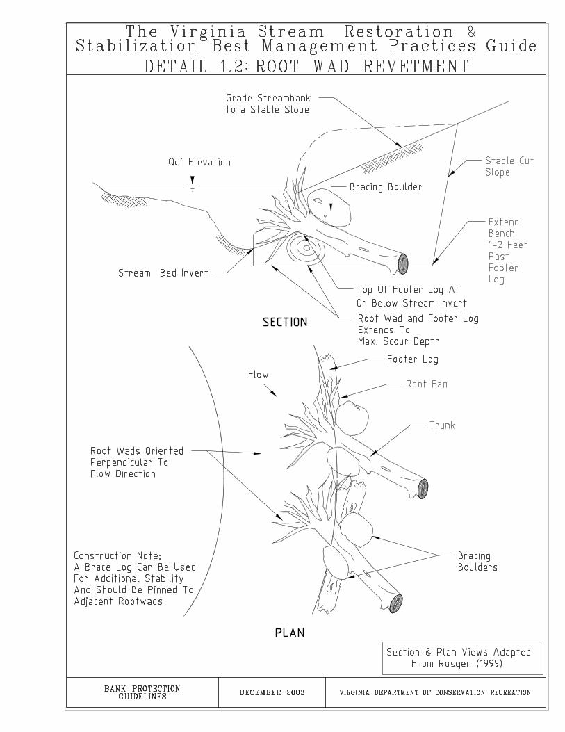

81
PRACTICE 1.3: STACKED STONERigid engineering technique for bank protection
DESCRIPTION
Layers of stacked angular rock built into the streambank in an imbricated (arranged with regular overlapping edges) fashion with a course of free draining gravel backfill behind it. Stacked stone provides rigid bank protection from erosion, mass wasting, and seepage.
APPROPRIATE USES
Areas where a highly durable bank protection is required due to soil conditions, near-bank erosional forces, expected vegetative cover, and groundwater conditions require a permanent structural treatment.
For areas where the proposed streambank slope is greater than 1:1 (Horizontal:Vertical).
In areas where potential for vegetative establishment is low or where woodyvegetation is not desirable.
LIMITATIONS
Heavy equipment is necessary for installation. The stone used for this technique is typically not a standard product and may require
hand selection at a quarry. The costs of quarrying, transporting, and placing the stone can be high.
DESIGN REQUIREMENTS AND PROCEDURES
A scour analysis should be performed to determine the depth of the toe trench. Minimum width for stacked stone is 1/3 the vertical height of the wall. Minimum
length of stone is 1.5 times the width. The minimum width for stacked stone is 24 inches.
Stacked stone walls higher than 10 feet in vertical height require structural engineering and geotechnical slope stability analysis.
MATERIAL SPECIFICATIONS
Filter Fabric: shall consist of a material meeting the requirement for filter fabric used with riprap as detailed in Table 3.19 D in section 3.19 of the Virginia Erosion and Sediment Control Handbook Third Edition, 1992, page III-171.
Toe Riprap: Rock revetment shall consist of an appropriately sized graded class of riprap as defined in the Virginia Erosion and Sediment Control Handbook Third Edition, 1992, Standard and Specification 3.19: Riprap. See Virginia Erosion and Sediment Control Handbook for detailed procedures in determining riprap class.

82
Stacked Stones: Stones should be blocky in shape such that they are stackable and sufficiently large to resist displacement by both the design storm event and the site-specific lateral earth stresses.
Porous Backfill: shall be VDOT Va. Size No. 78 or No. 8, minimum Grade B aggregate as described in Section 204—Stone For Masonry, Riprap, Porous Backfill, and Gabions of the VDOT Road and Bridge Specifications 2002.
Topsoil: Fertile, friable, loamy soil, containing not less than 1.5% organic matter;reasonably free from subsoil, refuse, roots, heavy or stiff clay, stones larger than 1 inch, coarse sand, noxious seeds, sticks, brush, litter, and other deleterious substances; suitable for the germination of seeds and the support of vegetative growth.
Staples: 0.125 inch diameter new steel wire formed into a “U” shape not less than 6 inches in length with a throat of 1 inch in width.
CONSTRUCTION RECOMMENDATIONS
Level of difficulty is high due to specialized materials and heavy equipment requirements.
A track hoe with a hydraulic or mechanical thumb is required to place stacked stones.
A contractor familiar with dry laid stone techniques can add valuable expertise and experience and enhance the success of the project.
INSTALLATION GUIDELINES
Loose material at the toe of the embankment should be excavated until a stable foundation is reached.
Excavate the streambank until a stable slope angle is achieved. The subgrade should be smooth, firm, and free from protruding objects or voids that would effectthe proper positioning of the first layer of stones and filter fabric.
Place filter fabric on the face of the cut slope and toe trench. Place filter fabric loosely and evenly on the prepared slope and secured with staples on 2 foot centers. Adjacent strips should overlap 12 inches and be stapled on 12 inch centers. The upslope filter fabric should always be placed over the downslope filter fabric. If the filter fabric is torn or damaged, it should be repaired or replaced.
Place footer rocks below the stream bed invert with the waterside edge of the footer rock at the proposed toe of slope. Footer stones should extend below the depth of potential scour.
Stack the first layer of rock ensuring that the rocks are stacked so the placed stone rests on two stones in the tier below it. Use smaller stones in voids between the tiers to ensure that stacked stones rest solidly on the tier below with minimal opportunity for movement.
Install toe trench to slightly below design scour depth. See PRACTICE 1.5: RockToe Revetment for guidance.
Place filter fabric and porous backfill at the completion of each tier of stacked stones.

83
Continue placing tiers of stones and porous backfill until the design height is achieved. Leave space for placement of topsoil behind the uppermost tier of stacked stone.
Place topsoil, tamp firmly, seed and water. Maximum finished slope is 2:1 (H:V) and must be at least 0.5% to achieve positive drainage.
Protect the upstream and downstream ends of the stacked stone wall with appropriately sized riprap. See Standard and Specification 3.19: Riprap of the Virginia Erosion and Sediment Control Handbook Third Edition, 1992 for information on sizing riprap.


85
PRACTICE 1.4: BOULDER REVETMENTSRigid technique for bank protection
DESCRIPTION
This technique consists of placing a boulder or boulders in the toe of the streambank to provide rigid toe protection.
APPROPRIATE USES
In areas of the lower streambank and toe that are subject to erosion and require a permanent, rigid toe protection.
When there is a local supply of appropriate boulders. Can be a single, double, or large boulder revetment. As the toe protection in an integrated bank treatment. Can be placed at near vertical slopes and therefore are useful in areas that are
horizontally constricted along the toe of the bank.
LIMITATIONS
Requires the use of heavy equipment. The costs of finding, transporting, and placing the stone can be high when compared
to PRACTICE 1.5: Rock Toe Revetment. Smaller streams may not have adequate bottom width to install boulders without
constricting the channel.
DESIGN REQUIREMENTS AND PROCEDURES
Treatment must extend vertically into the stream bed below the design scour depth. Boulders should be sized to withstand expected near-bank velocities and shear
stresses.
MATERIAL SPECIFICATIONS
Boulders: Large, irregularly shaped boulders collected onsite or found and transported. Size varies, but a minimum intermediate axis of 2 feet is recommended. For a single or large boulder revetment, the intermediate axis must extend below the depth of scour and above the normal baseflow elevation.
Filter Fabric: shall consist of a material meeting the requirement for filter fabric used with riprap as detailed in Table 3.19 D in section 3.19 of the Virginia Erosion and Sediment Control Handbook Third Edition, 1992, page III-171. A granular filter may be substituted for filter fabric. See standard and specification 3.19: Riprap for granular filter material specifications. If a granular filter is used, it should be at least 6 inches thick.

86
CONSTRUCTION RECOMMENDATIONS
A track hoe with a hydraulic or mechanical thumb is required to place boulders. Void spaces in between boulders can be planted with vegetation.
INSTALLATION GUIDELINES
Excavate a trench along the toe of the streambank to a depth slightly below the design scour depth.
Place filter cloth or install granular filter along backside of trench. Place filter fabric loosely and evenly on the prepared slope and secured with staples on 2 foot centers. Adjacent strips should overlap 12 inches and be stapled on 12 inch centers. The upstream or upslope filter fabric should always be placed over the downstream or downslope filter fabric. If the filter fabric is torn or damaged, it shouldbe repaired or replaced.
For single and double boulder revetments, place a layer of footer boulders at or slightly below the stream bed invert with the waterside edge of the footer boulder at the proposed toe of slope. Footer boulders should be flat and rectangular and provide an even surface for revetment boulders. Place revetment boulders on top of footer boulders to a height above the normal baseflow level.
For large boulder revetments, place the boulder in the trench with the longest axis oriented at a near vertical angle or parallel to the proposed streambank slope. Ensure that bottom of large boulder is below design scour depth and top of large boulder is above normal baseflow elevation.

89
PRACTICE 1.5: ROCK TOE REVETMENTRigid technique for lower bank protection
DESCRIPTION
A rock toe revetment involves placing a course of properly sized riprap at and above the streambank toe. This technique provides protection against erosion and creates a stable toe for the bank.
APPROPRIATE USES
In areas of the lower streambank that are prone to erosion and require permanent, rigid toe protection.
As the toe protection in an integrated bank treatment.
LIMITATIONS
Toe protection should not be used on actively incising streams unless measureshave been taken to promote vertical stability.
Riprap in channels is perceived as “unnatural” and may not be considered favorable by some stakeholders.
DESIGN REQUIREMENTS AND PROCEDURES
See Standard and Specification 3.19: Riprap of the Virginia Erosion and Sediment Control Handbook for design procedures.
Treatment must extend into the stream bed below the design scour depth and to an elevation above the normal baseflow elevation.
MATERIAL SPECIFICATIONS
Riprap: Standard and specification 3.19: Riprap of the Virginia Erosion and Sediment Control Handbook Third Edition, 1992 and Section 204—Stone For Masonry, Riprap, Porous Backfill, and Gabions of the VDOT Road and Bridge Specifications 2002.
Filter Fabric: shall consist of a material meeting the requirement for filter fabric used with riprap as detailed in Table 3.19 D in section 3.19 of the Virginia Erosion and Sediment Control Handbook Third Edition, 1992, page III-171. A granular filter may be substituted for filter fabric. See standard and specification 3.19: Riprap for granular filter material specifications. If a granular filter is used, it should be at least 6 inches thick.
CONSTRUCTION RECOMMENDATIONS
Void spaces may need to be hand chocked to achieve aesthetic slope and structural stability.

90
Requiring inspection of riprap or a gradation report prior to installation may prevent placing of improperly sized material.
Requires the use of heavy equipment for excavating the trench along the toe of the bank and for placement of the rock.
PRACTICE 2.6: Live Stakes can be placed in the voids between rocks to add vegetative stability. Drive live stakes into the voids until the basal end is in contact with native soil.
INSTALLATION GUIDELINES
Excavate a trench along the toe of the streambank to slightly below the design scour depth.
Place filter cloth or install granular filter along backside of trench. Place filter fabric loosely and evenly on the prepared slope and secured with staples on 2 foot centers. Adjacent strips should overlap 12 inches and be stapled on 12 inch centers. The upstream or upslope filter fabric should always be placed over the downstream or downslope filter fabric. If the filter fabric is torn or damaged, it should be repaired or replaced.
When used in combination with PRACTICE 2.3: Natural Fiber Matting, the matting should be stapled in place in the trench so that it will be firmly secured behind the riprap.
Place riprap starting in the bottom of the trench working up the bank. Riprap may have to be hand placed in voids to achieve desired result. Use smaller rock (<D15)to fill voids.


93
PRACTICE 1.6: LIVE CRIB WALLStructural system for bank protection with woody vegetation
DESCRIPTION
Live crib walls are hollow, box-like frameworks of logs or untreated timbers. The structure is filled with properly contained rock, soil and live branch cuttings. Live crib walls provide rigid and immediate toe and lower streambank protection and long term vegetative stability.
APPROPRIATE USES
In areas where erosion potential requires a rigid structural stream toe and bank. Where infrastructure constraints require steep finished bank slopes. When both a structural bank protection and a vegetative/natural practice are
required. To stabilize the lower portion of a cut or fill slope.
LIMITATIONS
Maximum height of 7-8 vertical feet and horizontal length of 20 feet. Arsenic-freetreated timbers can be used to construct larger structures.
Not intended to resist large lateral earth stresses. Live cribwalls should not be placed in areas that experience larger, lateral earth stresses or mass wasting.
Requires a stable toe. PRACTICE 1.4: Boulder Revetments recommended for use with moderate to large cribwall structures.
Site must be accessible by equipment. Site must be suitable to promote vegetative growth. Practice requires successful establishment and long-term survival of live branches.
Timbers decompose over time and live branches become structural bank protection.
DESIGN REQUIREMENTS AND PROCEDURES
Requires a stone toe. Stone toe must extend into the stream bed below the design scour depth and to an elevation above the normal baseflow elevation.
Structural engineering and geotechnical slope stability analysis are recommended for live cribwalls taller than 4 vertical feet.
MATERIAL SPECIFICATIONS
Front, Intermediate and Rear Beams: 4-12 inch diameter logs or 6”x8” hardwood timbers with a maximum length of 20 feet. Logs should have branches and bark removed. Removing bark improves rot resistance. Logs should be relatively straight and free of splits and rot.
Cross Beams: Same as above with length equal to the proposed height of the structure.
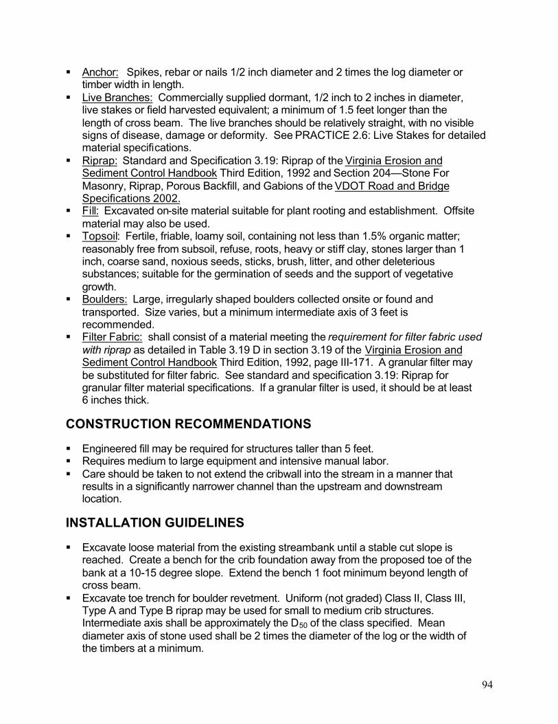
94
Anchor: Spikes, rebar or nails 1/2 inch diameter and 2 times the log diameter or timber width in length.
Live Branches: Commercially supplied dormant, 1/2 inch to 2 inches in diameter, live stakes or field harvested equivalent; a minimum of 1.5 feet longer than the length of cross beam. The live branches should be relatively straight, with no visible signs of disease, damage or deformity. See PRACTICE 2.6: Live Stakes for detailed material specifications.
Riprap: Standard and Specification 3.19: Riprap of the Virginia Erosion and Sediment Control Handbook Third Edition, 1992 and Section 204—Stone For Masonry, Riprap, Porous Backfill, and Gabions of the VDOT Road and Bridge Specifications 2002.
Fill: Excavated on-site material suitable for plant rooting and establishment. Offsite material may also be used.
Topsoil: Fertile, friable, loamy soil, containing not less than 1.5% organic matter; reasonably free from subsoil, refuse, roots, heavy or stiff clay, stones larger than 1 inch, coarse sand, noxious seeds, sticks, brush, litter, and other deleterious substances; suitable for the germination of seeds and the support of vegetative growth.
Boulders: Large, irregularly shaped boulders collected onsite or found and transported. Size varies, but a minimum intermediate axis of 3 feet is recommended.
Filter Fabric: shall consist of a material meeting the requirement for filter fabric used with riprap as detailed in Table 3.19 D in section 3.19 of the Virginia Erosion and Sediment Control Handbook Third Edition, 1992, page III-171. A granular filter may be substituted for filter fabric. See standard and specification 3.19: Riprap for granular filter material specifications. If a granular filter is used, it should be at least 6 inches thick.
CONSTRUCTION RECOMMENDATIONS
Engineered fill may be required for structures taller than 5 feet. Requires medium to large equipment and intensive manual labor. Care should be taken to not extend the cribwall into the stream in a manner that
results in a significantly narrower channel than the upstream and downstream location.
INSTALLATION GUIDELINES
Excavate loose material from the existing streambank until a stable cut slope is reached. Create a bench for the crib foundation away from the proposed toe of the bank at a 10-15 degree slope. Extend the bench 1 foot minimum beyond length of cross beam.
Excavate toe trench for boulder revetment. Uniform (not graded) Class II, Class III, Type A and Type B riprap may be used for small to medium crib structures. Intermediate axis shall be approximately the D50 of the class specified. Mean diameter axis of stone used shall be 2 times the diameter of the log or the width of the timbers at a minimum.

95
Follow procedures for installation of PRACTICE 1.4: Boulder Revetment for installation of filter fabric, footer boulder, and revetment boulder.
Place Riprap or aggregate in bench so that the top of the placed material is even with the top of the revetment boulder at their point of intersection. The placed material must slope away from this point if intersection at 10-15 degrees.
Place first course of front and rear beams on bench spaced 4-5 feet on center. For crib walls taller than 4-5 feet, a center beam is required. Space front, rear, and center beams equally. Leave room for 3-6 inch overlap of front and rear beam by cross beams.
Place cross beams perpendicular to front and rear beams. Allow 3-6 inch overlap at front and rear beam. Pound anchors through the cross beam into the underlying beam to a maximum of one-third the diameter/width of the underlying beam.
Backfill inside of structure with riprap in tiers below normal baseflow elevation. Continue filling tiers with riprap until above normal baseflow elevation.
For each tier above normal baseflow elevation, place 8-12 live branches per linear foot in a criss-crossed fashion, parallel to the cross beams. Orient live branches with buds facing upwards such that a minimum of 6 inches of the top end extends beyond the finished face of the cribwall and a minimum of 1 foot of the terminal ends extends beyond the back of the structure. Align live branches so that they extend on top of the front beam and extend underneath the rear beam for a given course. Cover live branches with an even course of topsoil, tamp and water thoroughly.
Repeat above three steps until design height is achieved. Backfill inside of structure above normal baseflow elevation with fill or fill amended with topsoil.


97
PRACTICE 1.7: INTERLOCKING CONCRETE JACKSPrefabricated concrete structures for lower-bank protection.
DESCRIPTION
Interlocking Concrete Jacks (commonly referred to as A-JacksTM, the name used by one manufacturer) are formed from two identical interlocking, pre-cast concrete armor units.The units assemble into a highly permeable, interlocking matrix, similar to toy jacks.Voids in the matrix are filled with soil and/or stone and provide a rigid and resistant streambank toe with limited void spaces for habitat and vegetative establishment.
APPROPRIATE USES
In areas of the lower streambank that experience significant erosion potential and require permanent, rigid toe protection.
As the toe protection in an integrated bank treatment. Where site access constrains bringing in heavy loads of riprap or wide trucks.
Interlocking Concrete Jacks come in pallets and can be brought in by smaller and lighter equipment. Small Interlocking Concrete Jacks can be carried by hand for short distances.
Can be used in conjunction with vegetative plantings to provide habitat and control lower bank erosion.
LIMITATIONS
Units can break during transport. Structures may break if impacted by debris. Instream debris loads should be
considered. Site must be accessible to heavy equipment if using large-sized Interlocking
Concrete Jacks. Intensive manual labor required.
DESIGN REQUIREMENTS AND PROCEDURES
Choose size and number of tiers of Interlocking Concrete Jacks to ensure they can withstand expected flow conditions and that the bottom-most Interlocking Concrete Jack is below the design scour depth and above the normal baseflow elevation.
If riprap is used to fill voids, choose a class with a D50 that is at least 1/3 the arm length of the Interlocking Concrete Jack.
MATERIAL SPECIFICATIONS
Interlocking Concrete Jacks: Two commercially supplied interlocking, identical pre-cast porous concrete armor units. Interlocking Concrete Jacks are available in arm lengths of 24”-96” arms. 24”-36” arms are typical for restoration of small to medium

98
size streams. The following table provides an example of one manufacturer’s Interlocking Concrete Jack sizes, dimensions and weights.
InterlockingConcreteJacks
L(in) T(in) H(in) C(in) Vol(ft3)
Wt(lbs)
AJ-24 24 3.36 3.68 1.84 0.56 78AJ-36 36 5.52 5.52 2.76 1.89 265AJ-48 48 7.36 7.36 368 4.49 629
Table 1.1. Example Interlocking Concrete Jack specifications. Source: Armortec (www.armortec.com)
Figure 1.1. Typical specified dimensions for Interlocking Concrete Jacks
Riprap: Standard and Specification 3.19: Riprap of the Virginia Erosion and Sediment Control Handbook Third Edition, 1992 and Section 204—Stone For Masonry, Riprap, Porous Backfill, and Gabions of the VDOT Road and Bridge Specifications 2002.
Fill: Excavated on-site material from installation of Interlocking Concrete Jacks. If using with dormant live cuttings, addition of topsoil to the fill is recommended.
Topsoil: Fertile, friable, loamy soil, containing not less than 1.5% organic matter; reasonably free from subsoil, refuse, roots, heavy or stiff clay, stones larger than 1 inch, coarse sand, noxious seeds, sticks, brush, litter, and other deleterious substances; suitable for the germination of seeds and the support of vegetative growth.
CONSTRUCTION RECOMMENDATIONS
Placing PRACTICE 2.6: Live stakes between and behind the Interlocking Concrete Jacks is recommended for added vegetative stability. Backfill with fill and topsoil when using live stakes. Minimize use of riprap when using live stakes to areas
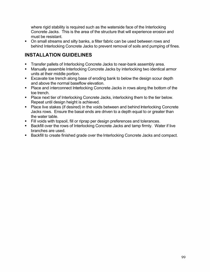
99
where rigid stability is required such as the waterside face of the Interlocking Concrete Jacks. This is the area of the structure that will experience erosion and must be resistant.
On small streams and silty banks, a filter fabric can be used between rows and behind Interlocking Concrete Jacks to prevent removal of soils and pumping of fines.
INSTALLATION GUIDELINES
Transfer pallets of Interlocking Concrete Jacks to near-bank assembly area. Manually assemble Interlocking Concrete Jacks by interlocking two identical armor
units at their middle portion. Excavate toe trench along base of eroding bank to below the design scour depth
and above the normal baseflow elevation. Place and interconnect Interlocking Concrete Jacks in rows along the bottom of the
toe trench. Place next tier of Interlocking Concrete Jacks, interlocking them to the tier below.
Repeat until design height is achieved. Place live stakes (if desired) in the voids between and behind Interlocking Concrete
Jacks rows. Ensure the basal ends are driven to a depth equal to or greater than the water table.
Fill voids with topsoil, fill or riprap per design preferences and tolerances. Backfill over the rows of Interlocking Concrete Jacks and tamp firmly. Water if live
branches are used. Backfill to create finished grade over the Interlocking Concrete Jacks and compact.


101
SECTION 2BANK STABILIZATION GUIDELINES
PRACTICE 2.1. NATURAL FIBER ROLLS
PRACTICE 2.2. LIVE SOIL LIFTS PRACTICE 2.3. NATURAL FIBER MATTING
PRACTICE 2.4. LIVE FASCINES
PRACTICE 2.5. BRUSH MATTRESSES PRACTICE 2.6. LIVE STAKES
PRACTICE 2.7. BRANCH LAYERING
Selected References Maryland Department of the Environment. 1999. Waterway Construction Guidelines.
Washington State Aquatic Habitat Guidelines Program. 2003. Integrated Streambank Protection Guidelines.
Miller, D. E. and T.R. Hoitsma. 1997. Fabric-encapsulated soil method of streambank bioengineering: Case Studies of Five Recent Projects. GeotechnicalFabrics Report 15(1): 48-53 (available from Interfluve, Inc. website (www.interfluve.com)).

103
PRACTICE 2.1: NATURAL FIBER ROLLSToe stabilization for enhancing bank stability
DESCRIPTION
A toe and lower bank protection technique using fiber rolls made from coir (coconut) fiber and netting. The natural fiber roll stabilizes the toe of the bank in areas of low stress. The natural fiber rolls promote trapping of sediment and provide a medium for the establishment of vegetation.
APPROPRIATE USES
Toe stabilization on gravel and sand bed streams with stable beds and base flow for a significant portion of the growing season.
Areas where an aesthetic and environmental treatment is preferred. Over time, the natural fiber roll degrades and the trapped sediments and plant materials become the stabilizing factor of the streambank.
As toe protection in ponds and lakes in areas with low erosion potential. Natural fiber rolls may be stacked in rows to form vertical tiers as a stabilization
measure for the lower portion of the streambank. Natural fiber rolls are typically used in combination with PRACTICE 2.3: Natural
Fiber Matting. Natural fiber rolls may also be placed in rows above a more rigid toe-protection
technique such as PRACTICE 1.5: Rock Toe Protection and PRACTICE 1.7: Interlocking Concrete Jacks.
LIMITATIONS
Natural fiber rolls should be avoided in channels with unstable beds that are actively incising/downcutting.
Long-term success of treatment assumes establishment of vegetation. Manufacturers estimate the product has an effective life of four to six years.
Natural fiber rolls are not appropriate in streams with bedrock or boulder beds because staking cannot be accomplished.
Not appropriate in reaches with large debris loads and/or potential for significant ice build up.
Encroachment of the fiber roll into the channel should be minimized. Follow manufacturers technical specifications for allowable water velocity or shear
stress based on the diameter of the natural fiber roll. Do not use natural fiber rolls in areas that exceed the maximum recommended shear stresses and velocities.
Care should be taken when rolls are placed in the outer meander bend because of the potential for significant erosional forces.

104
DESIGN REQUIREMENTS AND PROCEDURES
An analysis of near bank shear stress and/or velocity should be performed to determine that erosional forces are within the manufacturer’s technical specifications.
Used when minimal disturbance is required, as hand labor is often used for installation.
The stream’s normal baseflow level should keep 1/3 to 1/2 of the fiber roll submerged to ensure viability of plantings.
An investigation of the stream should be conducted to ensure there are no active downstream headcuts that may migrate upstream to the design site.
MATERIAL SPECIFICATIONS
Natural Fiber Roll: 100% mattress grade coir (coconut) fiber roll, min. 7 pounds per linear foot in 12, 16 or 20-inch diameter rolls, typically 20-feet in length with an outer netting comprised of 100% coir twine or yarn, with approximately 2 inches rhombic mesh openings, hand tied at the junctions. Yarn or twine with a tensile strength of 55 pounds when dry, or 40 pounds when wet. Maximum permissible shear stress and velocities vary by roll diameter and product specifications.
Plant Plugs: Vegetative plantings chosen according to their adaptability to site-specific soil, hydraulic, and hydrologic conditions and design objectives. PRACTICE 2.6: Live Stakes may be planted into the roll.
Hardwood stakes: Hardwood stakes (oak preferred) should be 2 inches by 2 inches with a length of 3 feet. Stakes should be notched on one side approximately 5 inches from the top of the stake to allow twine to be placed to anchor the roll.
Synthetic twine: tensile strength of 200 pounds, minimum.
CONSTRUCTION RECOMMENDATIONS
Logs must be kept dry prior to installation. Stakes may be placed directly opposite from each other on either side of the log or
alternating on either side along the length of the log.
INSTALLATION GUIDELINES
Excavate trench as necessary along the toe of the bank to place the natural fiber roll so that 1/2 to 2/3 of the roll will be below the normal baseflow elevation and the fiber roll will rest firmly against the streambank.
Staple in place PRACTICE 2.3: Natural Fiber Matting along bottom of trench if using in combination with natural fiber rolls.
Place natural fiber roll along the toe, tying together adjacent rolls with synthetic twine looped through the outer netting by making a number of passes in the end netting between the logs and pulling the twine taut. Where a fiber roll does not abut another fiber roll, the end should be bent inward and buried in the bank to prevent water from
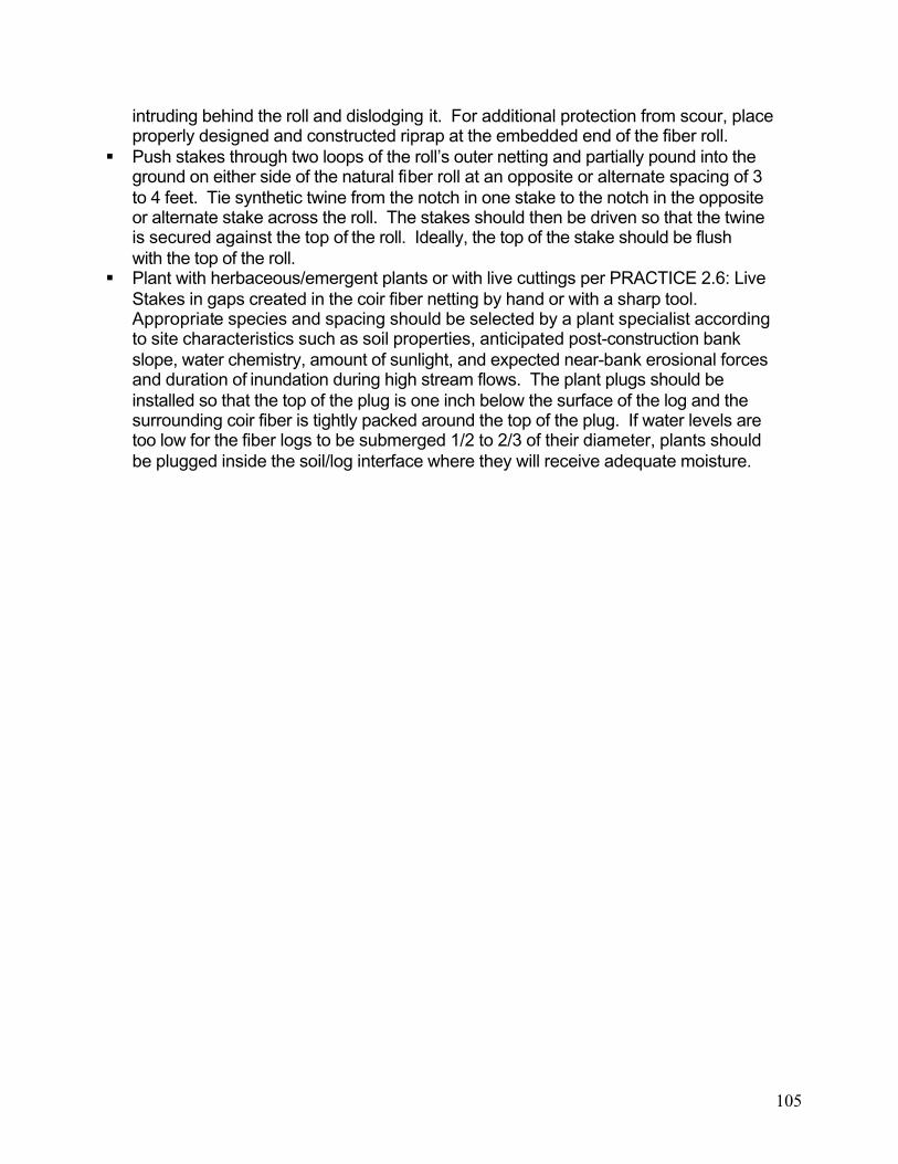
105
intruding behind the roll and dislodging it. For additional protection from scour, place properly designed and constructed riprap at the embedded end of the fiber roll.
Push stakes through two loops of the roll’s outer netting and partially pound into the ground on either side of the natural fiber roll at an opposite or alternate spacing of 3 to 4 feet. Tie synthetic twine from the notch in one stake to the notch in the opposite or alternate stake across the roll. The stakes should then be driven so that the twine is secured against the top of the roll. Ideally, the top of the stake should be flush with the top of the roll.
Plant with herbaceous/emergent plants or with live cuttings per PRACTICE 2.6: Live Stakes in gaps created in the coir fiber netting by hand or with a sharp tool. Appropriate species and spacing should be selected by a plant specialist according to site characteristics such as soil properties, anticipated post-construction bank slope, water chemistry, amount of sunlight, and expected near-bank erosional forces and duration of inundation during high stream flows. The plant plugs should be installed so that the top of the plug is one inch below the surface of the log and the surrounding coir fiber is tightly packed around the top of the plug. If water levels are too low for the fiber logs to be submerged 1/2 to 2/3 of their diameter, plants should be plugged inside the soil/log interface where they will receive adequate moisture.


107
PRACTICE 2.2: LIVE SOIL LIFTSBank protection technique for rebuilding and establishing stable streambanks
DESCRIPTION
The practice consists of constructing soil lifts above a toe protection. The soil lifts are comprised of material suitable for plant growth wrapped in natural fiber matting with live branches and topsoil placed between the lifts.
APPROPRIATE USES
In areas where there are concerns about shallow sliding, mass wasting, or internal seepage occurring in the streambank after the restoration is complete.
In areas where rebuilding an over widened/steep streambank requires placement of fill to establish final grade.
In areas where rebuilding the streambank requires fill, and the finished grade is 2:1 (Horizontal: Vertical) or steeper or for cut and fill slopes where the bank materials are non-cohesive (silts and sands).
As a component of a bank stabilization project in conjunction with PRACTICE 1.2:Rootwad Structures, PRACTICE 1.4: Boulder Revetment, PRACTICE 1.5: Rock Toe Revetment, PRACTICE 1.6: Live Crib Wall, and/or PRACTICE 1.7: InterlockingConcrete Jacks.
LIMITATIONS
Fill slopes steeper than 1.5:1 (H:V). Use of soil lifts requires a toe protection measure for areas below the normal or
spring baseflow elevation, as the lifts can deteriorate quickly in saturated conditions. Stability of the structure is dependent on the establishment of vegetation into the soil
lift and adequate toe protection. Not appropriate for use in areas that do not favor the establishment of vegetative
cover (due to low light levels, etc.).
DESIGN REQUIREMENTS AND PROCEDURES
Geotechnical analysis recommended. Select fill consisting of topsoil or a mix of topsoil and borrow free of sticks, stones,
and debris must be used to construct the soil lift. Sand, gravel, cobble, and clay are not suitable materials.
The contract document should contain an inspection and approval requirement for all materials to be used in the construction of soil lifts.
The contract document should include a guarantee/warranty regarding percent survivability of the live branches for a minimum of one year and a maximum of three years after installation.

108
MATERIAL SPECIFICATIONS
Live Branches: Commercially supplied or locally harvested dormant, 1/2” to 2” diameter, live stakes; 1-2 feet longer than the width of proposed soil lift. The live branches should be relatively straight, with no visible signs of disease, damage or deformity. See PRACTICE 2.6: Live Stakes for detailed material specifications.
Coarse Aggregate: Coarse aggregate as defined in the VDOT Road and Bridge Specifications 2002 Section 203-Coarse Aggregate.
Natural Fiber Matting: Machine produced woven un-seamed degradable natural fiber fabric with an outer layer and inner layer tied together at regular intervals meeting the following minimum specifications:
Material Outer: 100% coir (coconut) fiber twine (yarn). Inner: 100% jute twine (yarn).Thickness 0.30 inches Maximum Elongation (outer) 40% X 33%(Machine vs. Transverse) Tensile Strength (outer) 95 x 65 lbs/in (Machine vs. Transverse) (outer)Stiffness/Flexibility 0.0112 x 0.0071 lbs-inMass per unit area 29.5 oz/sq. ydWater Absorption 146%
Select Fill: Soil used to build the lifts shall be one of the following: Topsoil: Fertile, friable, loamy soil, containing not less than 1.5% organic
matter; reasonably free from subsoil, refuse, roots, heavy or stiff clay, stones larger than 2 inch, coarse sand, noxious seeds, sticks, brush, litter, and other deleterious substances; suitable for the germination of seeds and the support of vegetative growth. 50% Topsoil (described above); 50% Satisfactory Soil Material: ASTM D
2487 soil classification groups GW, GP, GM, SW, SP, SM, GC, SC, ML, and CL; free of rock or gravel larger than 1 inch in any dimension, debris, waste, frozen materials, vegetation and other deleterious matter.
Staples: 0.125 inch diameter new steel wire formed into a “U” shape not less than 6 inches in length with a throat of 1 inch in width.
CONSTRUCTION RECOMMENDATIONS
Soil Lifts should be used in combination with toe protection such as PRACTICE 1.2:Rootwad Structures, PRACTICE 1.4: Boulder Revetment, PRACTICE 1.5: Rock Toe Revetment, PRACTICE 1.6: Live Crib Wall, and PRACTICE 1.7: InterlockingConcrete Jacks for the portion of the streambank below the normal baseflow elevation.
Live branches should only be installed in the dormant season. This is the period after leaf drop in the fall and before bud break in the spring.
Natural fiber matting with an inner and outer layer meeting the specifications described above is required for soil lifts.

109
In dry periods, plant materials must be properly watered and maintained to ensure survival.
Fill placed behind the soil lifts should be placed in 8 inch lifts and properly compacted. Must be hand tamped and not mechanically compacted to ensure vegetative success.
Soil lifts are most commonly used in fill scenarios to re-establish an eroded streambank but can be used in cut scenarios. However, they require a large amount of excavation in this application.
INSTALLATION GUIDELINES
Live branches should be soaked for a minimum of 24 hours before planting. It should be noted that soaking for 5-7 days is considered ideal and promotes establishment.
The initial step in the installation of live soil lifts is to excavate the existing streambank slope until a stable, undisturbed surface is encountered. A flat bench should be created from the toe of the stable cut slope to the toe of the proposed streambank. Excavate a trench along the proposed toe of the streambank to accommodate the toe protection measure to be used.
Next, install the aggregate filter and toe protection. Place a lift of fill, behind the aggregate filter and compact properly. The aggregate filter should exhibit a 10-15degree slope away from the proposed streambank toe.
Place a batter board and jig (see detail 2.2b) and lay natural fiber matting along bottom of bench. Overlap adjacent matting by 1 foot.
Drape excess fabric over front of jig. Place select fill to a vertical depth of between 6 and 24 inches and a minimum of 4 feet in length along a 10- to 15-degree angleaway from the proposed streambank toe.
Tamp soil firmly. Apply seed mixture to front portion of lift that will be left exposed. Pull natural fiber matting over to cover lift and staple in place. After the soil lift is completed, the live branches are criss-crossed on top of the lift at
8 to 12 branches per linear foot. The basal end of the branches should extend at least 1 foot past the back of the soil lift. No more than 6 inches of the budding end of the live branch should extend past the front or finished face of the soil lift. Orient the branches so the exposed portions have their buds facing upwards and remove the terminal bud to promote root and stem development.
Cover the live branches with topsoil to create an even surface for the construction of the next lift.
Repeat the previous step and this step until a minimum of 3 soil lifts have been created. If there is less than 2 vertical feet of slope to be filled after three soil lifts have been created, then finish the slope.
In fill sections, soil lifts may be tapered back in areas where there is less than 4 horizontal feet of slope to be filled to avoid extra excavation. In this case, lifts that are one foot shorter than the lift below it can be built until less than 2 horizontal feetof slope remain to be filled. The slope can then be finished with natural fiber matting and compacted fill.

110
On both terminal ends of the soil lifts, excess matting shall be used to fold over the ends of the lift and stapled firmly. Backfill or fill adjacent to the end of the lift and compact to secure it firmly.


113
PRACTICE 2.3: NATURAL FIBER MATTINGTechnique for stabilizing raw earth banks using a machine-produced woven product
DESCRIPTION
The practice consists of placing and securing the natural fiber matting on a prepared slope. Typically a salvaged topsoil course is applied and the slope is seeded prior to placing the matting. In addition, trees and shrubs may be planted through the matting.
APPROPRIATE USES
As a stabilization measure on streambanks graded during construction. Graded streambanks with slopes of 2:1 (Horizontal:Vertical) or less. Used as an upper bank treatment in combination with a more rigid lower bank or toe
treatment. Used in combination with PRACTICE 2.1: Natural Fiber Roll for streams with low
erosional forces. Used as a component of PRACTICE 2.2: Live Soil Lifts. Used in combination with PRACTICE 2.6: Live Stakes.
LIMITATIONS
Should not be used for large fill sections and steeper fill slopes. For large fill sections, use PRACTICE 2.2: Live Soil Lifts.
Fiber matting biodegrades over time. Therefore, the established vegetation provides long-term stability to the bank.
Areas with higher velocities and shear stresses may require additional geosynthetic slope stabilization or erosion control matting. A hybrid product with a natural fiber layer and a geosynthetic layer may be suitable based on site conditions.
Should not be used in areas where livestock have access to the stream. Straw and jute matting are limited to use in floodplains and outside of main channel.
DESIGN REQUIREMENTS AND PROCEDURES
Select a natural fiber matting with a specified velocity and shear stress greater than or equal to the near bank velocity and shear stress of the design storm.
Ensure that the streambank is graded to a stable slope for use with natural fiber matting based on site-specific conditions and manufacturers specifications for the product.
MATERIAL SPECIFICATIONS
Natural Fiber Matting is available from many suppliers and in a number of different grades and combinations with other stabilization matting. Specifications for strawand jute matting are not given. Manufacturers can provide specifications and

114
recommendations on these products based on shear stress and velocities. There are many types of erosion control matting made of coir fibers. Shear stress is the main factor dictating the type of erosion control matting used. The following example represents the minimum specifications for a single layer matting consistingof a machine-produced woven coir yarn matting:
Material: 100% coir fiber twine or yarnMinimum Thickness: 0.30 inchesElongation (Dry/Wet): 33%/36% (approximate)Minimum weight: 11.8 oz/SYMaximum Open Area: 65%Minimum Life Expectancy: 3 yearsTensile Strength: 504 x 480 lbs/ftWater Velocity: 8 feet per secondShear Stress: 3.2 psi
Staples: 0.125 inch diameter new steel wire formed into a “U” shape not less than 6 inches in length with a throat of 1 inch in width.
Topsoil: Fertile, friable, loamy soil, containing not less than 1.5% organic matter; reasonably free from subsoil, refuse, roots, heavy or stiff clay, stones larger than 1 inch, coarse sand, noxious seeds, sticks, brush, litter, and other deleterious substances; suitable for the germination of seeds and the support of vegetative growth.
Plant Materials: The selection of plant materials is based on climate, topography, soils, land use and planting season. Vegetation established should, at a minimum, comply with table 3.22–B STD and SPEC 3.22 Vegetative Streambank Stabilization of the Virginia Erosion and Sediment Control Handbook.
CONSTRUCTION RECOMMENDATIONS
Site preparation is relatively easy. Bank grading may require the use of heavy equipment. Natural fiber matting should be stored in a secure area and protected from moisture. For high vertical slopes, unroll matting from top of bank to toe of bank. For
moderate to low vertical slopes unroll matting parallel with the face of the slope.
INSTALLATION GUIDELINES
Grade the banks to provide a smooth soil surface free from stones, clods, or debris. Place and tamp 2-inch deep course of topsoil.
Seed is applied to the graded bank prior to the installation of the matting. Seed should be lightly raked into the soil.
Unroll and place matting as recommended above. Ensure full contact of the matting with the topsoil and that the matting is free of tears, folds, holes, or other inconsistencies in its final placement.
If PRACTICE 1.5: Rock Toe Revetment or PRACTICE 2.1: Natural Fiber Roll is used in combination with matting, the lower end of the matting should be secured and buried behind the toe.

115
Where more than one roll of matting is required, the ends of each mat shall overlap one foot for both vertical and horizontal overlaps. Rolls that are overlapping along ends parallel to the bank shall be lapped such that the upstream roll is on top of the downstream role. Rolls that are overlapping along edges perpendicular to the bank shall be lapped such that the upslope roll is on top of the downslope roll.
Matting should extend 2 feet beyond the limits of grading at the top of slope and be keyed into a 6 inch deep trench. The matting is stapled in place along the bottom of the trench at 1 foot maximum spacing and the trench is backfilled and tamped. If there is no adjacent mat, the edge of the mat shall be keyed-in to a depth of 6 inches into the bank. If there is no toe treatment below the matting, the matting shall be keyed-in a minimum of 1 foot deep into the stream bed and backfilled with bed material at the toe of bank. Matting should be securely fastened in place with staples driven vertically into the soil and flush to the surface. Staples are placed two feet apart on center. Place staples across the matting at ends, overlaps, and key-intrenches, approximately 1 foot apart.


117
PRACTICE 2.4: LIVE FASCINESA woody vegetative measure to assist in bank stabilization
DESCRIPTION
Live fascines are bundles of dormant cuttings or branches bound together with twine and placed in covered trenches along the streambank parallel to the stream. When rooted, live fascines improve vegetative stabilization of the bank.
APPROPRIATE USES
Used to create breaks on long slopes. This traps sediment and intercepts runoff, thereby creating a series of functionally smaller slopes.
Used in combination and upslope of toe protection techniques such as PRACTICE1.5: Rock Toe Revetment or PRACTICE 2.1: Natural Fiber Roll. Can also be integrated with PRACTICE 2.3: Natural Fiber Matting.
Used for toe-protection in low energy streams. Have the potential to be used where shallow slide protection is required (less than
12”). Typically used above baseflow elevation.
LIMITATIONS
Not appropriate for use in situations where there are rocky soils, dry or well drained slopes or heavy shade that would limit growth of the cuttings.
Live fascines should only be installed during the dormant season. This is the period after leaf drop in the fall and before bud break in the spring.
Soil protecting the fascine may be eroded during high flows. Therefore, avoid use in lower bank areas unless covered with matting.
May require watering to ensure that cuttings establish. Requires that the toe of the streambank is stable in its existing condition or a stable
toe should be provided. Not appropriate on slopes undergoing mass movement.
DESIGN REQUIREMENTS AND PROCEDURES
Care should be taken when using fascines in areas with high shear stresses and velocities.
For 3:1 (Horizontal:Vertical) slopes or steeper, use in combination with PRACTICE 2.3: Natural Fiber Matting.
The contract document should include a guaranty / warranty regarding proper handling and installation of the live branches to promote survival and growth of the fascines.
The contract document should include a guarantee/warranty regarding percent survivability of the plant material used in the fascines for a minimum of one year and a maximum of three years after installation.

118
MATERIAL SPECIFICATIONS
Live Branches: Commercially supplied or field harvested, with diameters varying between 1/2 to 2 inches and length between 5 and 10 feet. The live branches should be relatively straight, with no visible signs of disease, damage or deformity.See PRACTICE 2.6: Live Stakes for detailed material specifications.
Synthetic Twine or Wire: Tensile strength of 200 pounds, minimum with 2mm diameter minimum.
Stakes: Stakes should be 2 by 4-inch lumber cut on the diagonal to a length of 3 feet.
CONSTRUCTION RECOMMENDATIONS
Manual labor is required to assemble and install the fascines. Live branches should only be installed in the dormant season. This is the period
after leaf drop in the fall and before bud break in the spring. Always construct the lowest fascine first and work upslope to construct additional
fascines. Place fascines at a slight angle to facilitate drainage on wet slopes. Place parallel to
the contour on dry slopes. When planning for live fascines, design should consider bundles 6 to 8 inches in
diameter. For flatter slopes, mulch, straw, or jute/straw matting should be used for slope
surface protection.
INSTALLATION GUIDELINES
Soak the live branches for a minimum of 24 hours in flowing water before planting. Soaking for 5-7 days is considered ideal and should promote establishment.
Assemble the fascine by laying out live branches with the cut ends placed in opposite directions in a long sausage-like bundle.
Tie bundles with twine at 12”-18” increments. Finished bundles should be between 6 and 9 inches in diameter.
Fascines should be installed beginning at the lowest elevation on the bank and continuing upslope.
Excavate a horizontal trench along the slope. The trench should be one inch deeper than the diameter of the bundle for total coverage of the fascine. If the bundle is not to be covered fully, the trench should be 2/3 the diameter of the bundle.
Place bundles in trench backfill, tamp and water. Cover with matting, if desired. Stake at a 2-4 foot spacing through the center of the bundle. Leave 3 inches of
stakes above bundle. Repeat above steps for upslope fascines. For a guide in fascine spacing, see the
following chart:

119
Table 2.1 Fascine SpacingSlope H:V Slope distance
between trenches (ft) Dry Slope
Slope distance between trenches (ft) Wet Slope
Maximum slope length (ft)
1.5:1 to 2:1 4-5 3-5 202:1 to 2.5:1 5-6 3-5 302.5:1 to 3:1 6-8 4-5 403:1 to 4:1 8-9 6-9 504:1 to 5:1 9-10 9-10 60
Source: USDA 1992


121
PRACTICE 2.5: BRUSH MATTRESSESA woody vegetative measure to assist in bank stabilization
DESCRIPTION
Brush mattresses are formed from dormant live branches that are bound together to create a mat used to protect against erosion. This mat is secured to the bank by live and/or dead stakes and partially covered with topsoil.
APPROPRIATE USES
For areas where protection is needed to establish a vegetative cover. Where total coverage of slope with vegetation is desirable. On slopes less than 2:1 (Horizontal:Vertical). Maximum slope length is 10 feet.
LIMITATIONS
Not suited for slopes experiencing mass movement. Requires a stable toe below the brush mattress (existing or provided). Watering may be required in dry periods. Brush mattresses should only be installed during the dormant season. This is the
period after leaf drop in the fall and before bud break in the spring. Drains or geotextiles may be required if there is a potential for seepage under the
brush mattress.
DESIGN REQUIREMENTS AND PROCEDURES
Brush mattresses must be designed and constructed to withstand the near bank shear stresses and velocities that impact the streambank.
Brush mattresses should achieve approximately an 80% cover in the area of application.
The contract document should include a guaranty/warranty regarding proper handling and installation of the live branches to promote survival and growth of the brush mattresses.
The contract document should include a guarantee/warranty regarding percent survivability of the live branches for a minimum of one year and a maximum of three years after installation.
MATERIAL SPECIFICATIONS
Live Branches: Commercially supplied or field harvested, with diameters varying between 1/2 to 2 inches and lengths between 5 and 10 feet. The live branches should be relatively straight, with no visible signs of disease, damage or deformity.See section PRACTICE 2.6: Live Stakes for detailed material specifications.

122
Hardwood stakes: Hardwood (oak preferred) 2 inches by 2 inches by 3 feet in length. Stakes should be notched on one side approximately 2 inches from theirtops.
Synthetic Twine or Wire: Tensile strength of 200 pounds, minimum with 2mm diameter minimum.
Topsoil: Fertile, friable, loamy soil, containing not less than 1.5% organic matter; free from subsoil, refuse, roots, heavy or stiff clay, stones, coarse sand, noxious seeds, sticks, brush, litter, and other deleterious substances; suitable for the germination of seeds and the support of vegetative growth. The pH value shall be between 6.0 and 7.5.
CONSTRUCTION RECOMMENDATIONS
Manual labor is required to assemble and install brush mattresses. Live branches should only be installed in the dormant season. This is the period
after leaf drop in the fall and before bud break in the spring.
INSTALLATION GUIDELINES
Soak the live branches for a minimum of 24 hours before planting. Soaking for 5-7days is considered ideal and should promote establishment.
Starting at the lowest position on the slope to be stabilized with brush mattresses, lay the live branches vertically on the bank with their basal (bottom) end toward the water and the bud end toward the top of the bank. Use approximately 5 to 15 live branches per linear foot of streambank length. The thickness of the mattress should be 6-9 inches.
Drive stakes a minimum of 2 feet into the ground on a grid or square pattern. Space stakes 2-3 feet apart.
Stand on the brush mattress and tie the wire or string in a diamond pattern around the stakes. Wrap the wire or string firmly around the notch in the stake.
Drive the stakes as far as possible to compress and secure the branches firmly against the streambank.
Place topsoil on the top of the branches, work topsoil into the branches with water, and repeat until the depth of soil equals at least 3/4 of the depth of the mattress. Water thoroughly when completed.
For adjacent upslope mattresses, overlap 1-2 feet. The upslope mattress should overlap the downslope mattress.


125
PRACTICE 2.6: LIVE STAKES
Vegetative technique to assist in bank stabilization
DESCRIPTION
Live stakes are dormant woody cuttings that are driven into the soil to root, grow, and create vegetative cover to stabilize the streambank.
APPROPRIATE USES
Used to stabilize graded or eroding streambanks where a natural, vegetative practice is preferred.
Used as an integrated component of all the practices described in Chapter 4, Sections 1 and 2 of this guide. Live staking combined with other practices can add an additional measure of stability.
Can be used as a stand-alone practice on 4:1 (Horizontal:Vertical) or gentler slopes. As a streambank stabilization method above a toe treatment such as PRACTICE
2.1: Natural Fiber Roll or PRACTICE 1.5: Rock Toe Revetment.
LIMITATIONS
Limited use in areas with low moisture and rocky soils, and high, dry banks. Most successful where stakes will have some contact with a seasonally high water table.
Live stakes must be planted after leaf drop in the fall and before bud burst in the spring.
Live stakes will not establish well in shaded areas and north facing slopes. Most species will not thrive below normal or spring baseflow elevation. Select wetter
tolerant species such as Buttonbush for areas near or below baseflow elevation. May require watering. Vegetation growth is relatively slow compared to other methods. Depending on the species planted, may be prone to beaver predation. May require regular cutting back to maintain aesthetic preferences in urban areas.
On small streams, live stakes on both banks tend to promote a closed canopy. This may be perceived as unsafe or unattractive. The vegetation may also collect litter in streams adjacent to roads.
DESIGN REQUIREMENTS AND PROCEDURES
Do not use in areas where near-bank shear stress exceeds 2lb/ft2 or velocities exceed 5-10 fps.
Stake lengths should be long enough to reach soil suitable for rooting when used with other practices.
Select species to match site conditions, including shading, flood and drought tolerances, and aesthetics.

126
The contract document should include a guaranty/warranty regarding proper handling and installation of the live branches to promote survival and growth of the live stakes.
The contract document should include a guarantee/warranty regarding percent survivability of the live branches for a minimum of one year and a maximum of three years after installation.
MATERIAL SPECIFICATIONS
Live stakes: Commercially supplied or field harvested, dormant stakes with diameters ranging from 1/2” to 2 inches; length determined by application. The live stakes should be relatively straight, with no visible signs of disease, damage or deformity. The stakes should have all side branches removed. The bottom or basal end of the cutting should be cleanly cut at a 45 degree or sharper angle and the top end should be cut square (flat). Stakes must be harvested after leaf drop in the fall and before bud break in the spring. The use of rooting hormone Indoleacetic acid (IAA) will increase success of live stakes. The following native species are viable for use as dormant, live planting material in
the Commonwealth of Virginia. Note that some species may not be native to particular regions of the state.

127
Common Name/Scientific Name Region Tolerance
to FloodingToleranceto Drought
Toleranceto
Deposition
Toleranceto Shade
Box elderAcer negundo
C, P, M H H H L
Groundsel bushBaccharis halimifolia C, P (lower) M M H L
ButtonbushCephalanthusoccidentalis
C, P, M H L L L
Silky dogwoodCornus amomum P, M L M L M
Red osier dogwoodCornus stolonifera P, M L M H M
Eastern cottonwoodPopulus deltoides
C, P, M M M H L
Bankers willow*Salix cotteti P, M H M H L
Black willowSalix nigra C. P. M H H H L
Streamco willow**Salix purpurea
C, P, M H H H L
American elderberrySambucuscanadensis
P, M H M M M
Southern arrowwoodViburnum dentatum C, P, M M M M M
NannyberryViburnum lentago
C, P, M M M L M
Source: Adapted from the USDA Soil Conservation Service Engineering Field Handbook, Chapter 18*Bankers willow – hybrid, naturalized, may be considered noxious by some agencies**Streamco willow – introduced, naturalized, may be considered noxious by some agencies
Legend:Tolerance to flooding, drought, deposition, and shadeH=high, M=medium, L=lowRegionC=Coastal Plain, P=Piedmont, M=Mountains
CONSTRUCTION RECOMMENDATIONS
Live stakes must be installed after leaf drop in the fall and before bud break in the spring.
Stakes that are splintered, split or broken during installation must be replaced. The use of a punch/planting bar or an auger may be used to pre-drive a hole for live
stakes. Live staking is often one of the last construction activities in streambank stabilization
and protection work and is accomplished manually. Therefore, it provides a good opportunity for volunteer efforts.
Store live stakes in a cool, shaded location in damp peat moss, sand, wrapped in newspaper in ventilated plastic bags, or in burlap sacks and topsoil for a maximum

128
of 48 hours. If live branches cannot be installed within 48 hours of delivery, then they shall be stored in a cooler between 33 and 40 degree Fahrenheit in one of the moist mediums listed above. If live stakes are stored onsite, the storage locations should be continually shaded and protected from wind and direct sunlight. Live branches shall remain moist at all times before planting.
Live branch cuttings should be shipped within 48 hours after harvesting, and should be shipped next-day or 2-day.
INSTALLATION GUIDELINES
Soak the live branches for a minimum of 24 hours before planting. Soaking for 5-7days is considered ideal and should promote establishment.
Drive stake directly into the streambank, basal/angled end first. Stakes can set vertically or perpendicular to the bank angle. Use an auger or punch/planting bar to create a pilot hole slightly smaller than diameter of stake, as needed.
Tap the stake into the ground using a rubber mallet so that 80% of the length of the stake is below finished grade and 20% of the length of the stake is above finished grade.
Using loppers, cut stakes after installation, leaving 3 inches exposed above ground. Fill the hole as needed with topsoil and water slurry. Tamp around the stake and
water. Place stakes in squared or staggered rows at 1-4 foot spacing. This achieves a
typical density of 2 to 4 stakes per square yard.

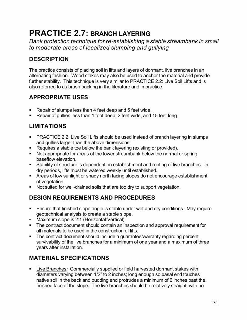
131
PRACTICE 2.7: BRANCH LAYERINGBank protection technique for re-establishing a stable streambank in small to moderate areas of localized slumping and gullying
DESCRIPTION
The practice consists of placing soil in lifts and layers of dormant, live branches in an alternating fashion. Wood stakes may also be used to anchor the material and provide further stability. This technique is very similar to PRACTICE 2.2: Live Soil Lifts and is also referred to as brush packing in the literature and in practice.
APPROPRIATE USES
Repair of slumps less than 4 feet deep and 5 feet wide. Repair of gullies less than 1 foot deep, 2 feet wide, and 15 feet long.
LIMITATIONS
PRACTICE 2.2: Live Soil Lifts should be used instead of branch layering in slumps and gullies larger than the above dimensions.
Requires a stable toe below the bank layering (existing or provided). Not appropriate for areas of the lower streambank below the normal or spring
baseflow elevation. Stability of structure is dependent on establishment and rooting of live branches. In
dry periods, lifts must be watered weekly until established. Areas of low sunlight or shady north facing slopes do not encourage establishment
of vegetation. Not suited for well-drained soils that are too dry to support vegetation.
DESIGN REQUIREMENTS AND PROCEDURES
Ensure that finished slope angle is stable under wet and dry conditions. May require geotechnical analysis to create a stable slope.
Maximum slope is 2:1 (Horizontal:Vertical). The contract document should contain an inspection and approval requirement for
all materials to be used in the construction of lifts. The contract document should include a guarantee/warranty regarding percent
survivability of the live branches for a minimum of one year and a maximum of three years after installation.
MATERIAL SPECIFICATIONS
Live Branches: Commercially supplied or field harvested dormant stakes with diameters varying between 1/2” to 2 inches; long enough so basal end touches native soil in the back and budding end protrudes a minimum of 6 inches past the finished face of the slope. The live branches should be relatively straight, with no
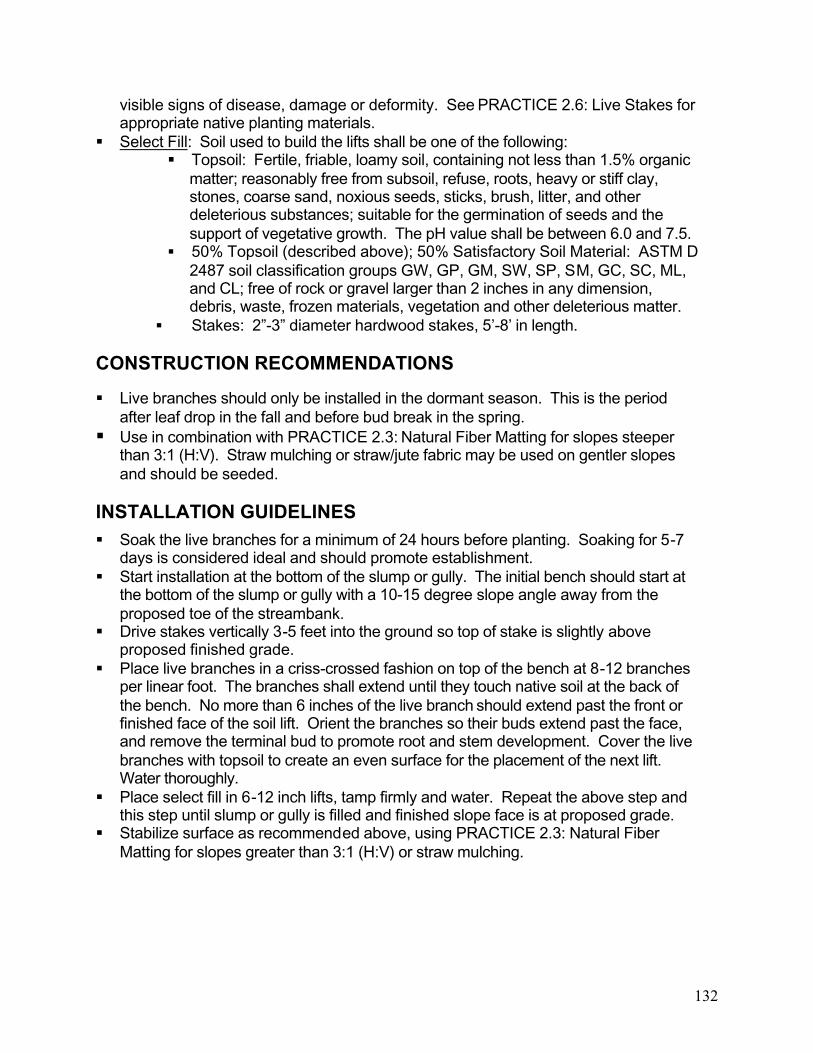
132
visible signs of disease, damage or deformity. See PRACTICE 2.6: Live Stakes for appropriate native planting materials.
Select Fill: Soil used to build the lifts shall be one of the following: Topsoil: Fertile, friable, loamy soil, containing not less than 1.5% organic
matter; reasonably free from subsoil, refuse, roots, heavy or stiff clay, stones, coarse sand, noxious seeds, sticks, brush, litter, and other deleterious substances; suitable for the germination of seeds and the support of vegetative growth. The pH value shall be between 6.0 and 7.5.
50% Topsoil (described above); 50% Satisfactory Soil Material: ASTM D 2487 soil classification groups GW, GP, GM, SW, SP, SM, GC, SC, ML, and CL; free of rock or gravel larger than 2 inches in any dimension, debris, waste, frozen materials, vegetation and other deleterious matter.
Stakes: 2”-3” diameter hardwood stakes, 5’-8’ in length.
CONSTRUCTION RECOMMENDATIONS
Live branches should only be installed in the dormant season. This is the period after leaf drop in the fall and before bud break in the spring. Use in combination with PRACTICE 2.3: Natural Fiber Matting for slopes steeper
than 3:1 (H:V). Straw mulching or straw/jute fabric may be used on gentler slopes and should be seeded.
INSTALLATION GUIDELINES Soak the live branches for a minimum of 24 hours before planting. Soaking for 5-7
days is considered ideal and should promote establishment. Start installation at the bottom of the slump or gully. The initial bench should start at
the bottom of the slump or gully with a 10-15 degree slope angle away from the proposed toe of the streambank.
Drive stakes vertically 3-5 feet into the ground so top of stake is slightly above proposed finished grade.
Place live branches in a criss-crossed fashion on top of the bench at 8-12 branches per linear foot. The branches shall extend until they touch native soil at the back of the bench. No more than 6 inches of the live branch should extend past the front or finished face of the soil lift. Orient the branches so their buds extend past the face, and remove the terminal bud to promote root and stem development. Cover the live branches with topsoil to create an even surface for the placement of the next lift.Water thoroughly.
Place select fill in 6-12 inch lifts, tamp firmly and water. Repeat the above step and this step until slump or gully is filled and finished slope face is at proposed grade.
Stabilize surface as recommended above, using PRACTICE 2.3: Natural Fiber Matting for slopes greater than 3:1 (H:V) or straw mulching.
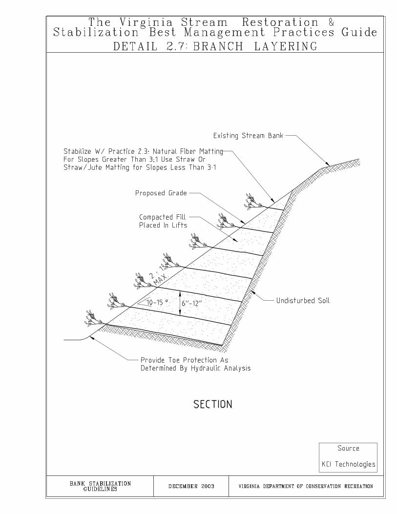

135
SECTION 3GRADE CONTROL STRUCTURES GUIDELINES
PRACTICE 3.1. ROCK CROSS VANES PRACTICE 3.2. ROCK W WEIRS
PRACTICE 3.3. ROCK VORTEX WEIRS PRACTICE 3.4. STEP POOLS
PRACTICE 3.5. LOG DROPS AND V LOG DROPS
Selected References Zimmermann, S. ad M. Church. 2001. Channel Morphology, Gradient profiles and bed stresses during flood in a step-pool channel. Geomorphology 40:311-327.
Chin, A. 1999. The morphological structure of step-pools in mountain streams. Geomorphology 27: 191-204.
Rosgen, D. 2001. The Cross-vane, W-Weir and J-Hook Vane Structures. Their description, design and application for stream stabilization and river restoration. ASCE Conference, Reno, NV, 2001
Moses, T. and M. Lower. Natural Channel Design of Step-pool Watercourses Using the “Keystone” Concept. http://www.pubs.asce.org/journals/EWRINatChannelDesign.pdf

137
PRACTICE 3.1: ROCK CROSS VANESIn-stream rock structure for directing erosional forces away from the streambanks and establishing grade control
DESCRIPTION
A rock cross vane is a stone structure consisting of footer and vane rocks constructed in a way that provides grade control and reduces bank erosion. The vane is composed of a center section perpendicular to the streambanks joined to two arms that extend into the streambank at the Qcf height. The rock cross vane accumulates sediment behind the vane arms, directs flow over the cross vane, and creates a scour pool downstream of the structure.
APPROPRIATE USES
Where stabilization of a vertically unstable stream bed requires grade control. To direct erosional forces away from the streambanks and to the center of the
channel. When fish habitat enhancement and grade control are both desired. For bridge protection, cross vanes provide grade controls, prevent lateral migration
of channels, increase sediment transport capacity and competence, and reduce footer scour.
To enhance or create recreational paddling opportunities. Most suitable for rapid-dominated stream systems (Rosgen Class B) with
gravel/cobble substrate.
LIMITATIONS
The Qcf height must be accurately located for the stream as the vane arm is set into the streambank at the Qcf elevation.
Rock cross vanes used in streams with a significant portion of sand, silt or clay in their beds must be sealed using filter fabric and/or a properly sized and placed open class aggregate.
Large rock size requirements make it difficult to use in small streams. Requires heavy equipment and skilled operators to place rock correctly. Rock may sink or subside in streams with sand and clay beds, which makes proper
construction difficult. Additional foundation design may be required.
DESIGN REQUIREMENTS AND PROCEDURES
Vane arms should intersect the bank at an angle between 20 and 30 degrees. The angle is measured upstream from the tangent line where the vane intercepts the bank. A smaller angle produces a longer arm. A longer arm provides more linearfeet of bank protection.
Vane arm slopes range from 2-15 percent. The center vane is flat (no slope). When designing cross vanes in larger systems, a 2-7 percent slope can result in excessive

138
vane arm lengths. The designer can choose a steeper slope for the vane arms when practical. However, steeper vanes tend to be less stable.
Specify elevation and offset values for both ends of the vane arms. This ensures exact placement of the structure by the contractor.
Always use at least two vane rocks for the middle 1/3 of the structure. Streams have a tendency to erode around a single vane rock in the middle of the structure.
Rock cross vanes may create blockages to fish migration. Vane rocks in the center 1/3 of the structure can be gapped to allow fish passage. However, when rocks are gapped, it is important to understand that the top of the footer rock becomes the invert elevation for grade control, not the top of the vane rocks.
Designer must specify a design depth for the scour pool immediately downstream of the cross vane. A scour depth analysis is recommended to aid in specifying the depth.
Cross vane arms must terminate at the Qcf elevation. If the top of bank is above Qcf elevation, then a floodplain bench should be created at the Qcf elevation.
Rock cross vanes should be designed for a maximum vertical drop (protrusion height) of 6 inches. If more than 6 inches of drop is required over a short section of stream, use a series of step pools per PRACTICE 3.4: Step Pools.
For designs using multiple cross vanes to achieve grade control the following rule of thumb can be used to determine spacing of structures along the stream channel:
Ps=8.2513S-0.9799
Where Ps=the ratio of pool to pool spacing/Qcf widthS=Channel slope in percent
This relationship is derived from data on natural streams and rivers with slope generally greater than 2% (Rosgen 2001).
MATERIAL SPECIFICATIONS
Rock: Footer and vane rocks must be large enough to achieve the design height and appropriately sized to resist movement due to stream flow characteristics.Rocks shall be relatively rectangular in shape, uniform in size, and have a minimum intermediate (b) axis greater than 1.5 feet (0.5 meters) at a minimum. An example of rock size as a function of Qcf shear stress is given below:

139
Figure 3.1: Minimum Rock Size for Rock Cross Vane’s as a function of Qcf shear stress. Source: Rosgen 2001. Riprap: Riprap per Standard and Specification 3.19: Riprap of the Virginia Erosion
and Sediment Control Handbook for sill rocks, bank armoring, and toe protection. Open Class Aggregate: If used for sealing behind structure, should be properly
sized to be minimally mobilized and displaced in supercritical flow events. Salvaged alluvial channel material can be substituted for aggregate if properly sized.
Filter Fabric: If used for sealing the structure, filter fabric shall consist of a material meeting the requirement for filter fabric used with riprap as detailed in Table 3.19 D in section 3.19 of the Virginia Erosion and Sediment Control Handbook Third Edition, 1992, page III-171. A granular filter may be substituted for or used with filter fabric. See Standard and Specification 3.19: Riprap for granular filter material specifications.
CONSTRUCTION RECOMMENDATIONS
Placement of rock requires a track hoe with a hydraulic thumb. Require an inspection of the rock material before it is placed. Rock size and shape
requirements are specific and often inappropriate material is installed and must be removed or ultimately leads to structural failure.
Rock cross vanes must be sealed with filter fabric, a properly sized and placed open class filter aggregate, and/or riprap if the channel bed material is fine enough to pass the structure. This is especially true in sand, silt, and clay stream beds. Material passing through the structure can fill the scour pool. In addition, passing of bed material undermines one of the key benefits of the structure, which is the accumulation of sediment behind the rock cross vane.
Ensure no leakage/flow under or around the structure by properly grading, sealing, and compacting under and around the structure.
After installation, check proper function/flow path by observing flow over structure. Repair as needed to ensure proper function.

140
INSTALLATION GUIDELINES
Excavate a trench along the bottom of the stream bed and to the Qcf elevation in the streambank for the center section and arms of the cross vane. The trench should be perpendicular to the streambanks in the middle 1/3 Qcf width for the center sectionand excavated to the design angle in the 1/3 Qcf width for each arm. The vane arms should be properly tied into the bank at the Qcf elevation. Excavate a Qcf bench if the top of bank is not at the Qcf elevation. The trench shall be excavated to the minimum footer rock depth (see description below).
Place one or two courses of footer rocks to the minimum footer rock depth. The minimum footer rock is measured from the stream bed invert and is equal to a depth 3 times the protrusion height of the vane rock for cobble and gravel bed streams and 6 times the protrusion height for sand bed or finer streams (see detail 3.1). Be sure to leave space above the footer rocks for the below invert portion of the vane rocks
Place vane rocks on top of footer rocks so that each half of the vane rock rests on one half of a footer rock below. Offset the vane rock in the upstream direction and place so they slope slightly against the flow direction. A portion of the vane rocks should be below the stream bed invert with a portion above the invert to the specified protrusion height. The maximum protrusion height is 6 inches.
Extend the structure into the bank a minimum of 2 feet at the Qcf elevation, and armor with riprap upstream and downstream as needed for stability.
At the Qcf elevation, create a sill of placed rock perpendicular to the streambank extending away from the end of the vane arm. Construct the sill per PRACTICE 4.5: Cut-Off Sills and Linear Deflectors. The rock should be smaller than the vane and footer rocks but large enough to resist displacement during high flow events.
Seal the structure on the upstream side for streams with a high proportion of sand, clay, and silt bed material. The detail below (figure 3.2) shows a typical sealing scenario for rock cross vanes.
Excavate the scour pool to the design depth.
Figure 3.2. Typical sealing detail for rock grade control structures. Adapted from Buck Engineering.


143
PRACTICE 3.2: ROCK W-WEIRSIn-stream rock structure for directing erosional forces away from the streambanks and establishing grade control. Rock W-Weirs are similar to Rock Cross Vanes with the W shape pointing upstream and creating two scour pools.
DESCRIPTION
A rock W-weir is a stone structure consisting of footer and vane rocks that provides grade control and reduces bank erosion. The weir consists of four weir arms arranged in a “W” fashion across the channel. The weir accumulates sediment behind the weir arms and creates two scour pools downstream of the structure.
APPROPRIATE USES
W-weirs are best used in streams with Qcf widths greater than 40 feet. Where restoration of an unstable stream bed requires a fixed stream bed elevation. To direct erosional forces away from the streambank and to the center of the
channel. When fish habitat enhancement and/or grade control are desired. For protection of 3 cell/two pier bridge. W-weirs provide grade control, prevent lateral
migration of channels, increase sediment transport capacity and competence, andreduce footer scour.
To enhance or create recreational paddling opportunities.
LIMITATIONS
The Qcf height must be accurately located for the stream as the vane arm is set into the streambank at the Qcf elevation.
W-weirs used in streams with a significant portion of sand, silt or clay in their beds must be sealed using filter fabric or a properly sized and placed open class aggregate.
Large rock size requirements and the W-shaped pattern make it difficult to use in smaller streams (less than 40 foot width).
Requires heavy equipment and skilled operators to place rock correctly. Rock may sink or subside in streams with sand and clay beds, which makes proper
construction difficult.
DESIGN REQUIREMENTS AND PROCEDURES
Weir arm should intersect the bank at an angle between 20 and 30 degrees. The angle is measured upstream from the tangent line where the weir intercepts the bank. A smaller angle produces a longer arm. A longer arm provides more linear feet of bank protection.
Weir arm slopes are typically 2-15 percent. When designing W-weirs in larger systems, a 2-7 percent slope can result in excessive weir arm lengths. The designer

144
can choose a steeper slope for the weir arms when practical. However, steeper weirs tend to be less stable, and protect less of the bank.
Specify elevation and offset values for both ends of all four weir arms. This ensures exact placement of the structure by the contractor.
W-weirs may create blockages to fish migration. Weir rocks in the center 1/2 of the structure can be gapped to allow fish passage. However, when rocks are gapped, it is important to understand that the top of the footer rock becomes the invert elevation for grade control, not the top of the vein rocks.
Designer must specify a design depth for the two scour pools immediately downstream of the W-weir. A scour depth analysis is recommended to aid in this effort.
The outer two weir arms must terminate at the Qcf elevation. If the top of bank is above Qcf, the outer weir arms must be properly connected or entrenched into the bank at the Qcf elevation and a Qcf bench must be created at the Qcf elevation.
Rock W-weirs should be designed for a maximum vertical drop (protrusion height) of 6 inches. If more than 6 inches of drop is required over a short section of stream, use a series of step pools with 6 inch drops per PRACTICE 3.4: Step Pools.
For designs using multiple W-weirs to achieve grade control, the following rule of thumb can be used to determine spacing of structures along the stream channel:
Ps=8.2513S-0.9799
Where Ps=the ratio of pool to pool spacing/Qcf widthS=Channel slope in percent
This relationship is derived from data on natural streams and rivers with slope generally greater than 2% (Rosgen 2001).
MATERIAL SPECIFICATIONS
Rock: Footer and weir rocks must be large enough to achieve the design height and appropriately sized to resist movement due to stream flow characteristics. Rocks shall be relatively rectangular in shape, uniform in size, and have a minimum intermediate axis greater than 1.5 feet. An example of rock size as a function of Qcf shear stress is given in Figure 3.1 of PRACTICE 3.1: Rock Cross Vanes.
Riprap: Riprap per Standard and Specification 3.19: Riprap of the Virginia Erosion and Sediment Control Handbook as needed for sill rocks, bank armoring, and toe protection.
Open Class Aggregate: Used for sealing behind structure. Should be properly sized to be minimally mobilized and displaced in supercritical flow events. Salvaged alluvial channel material can be substituted for aggregate if properly sized.
Filter Fabric: If used for sealing the structure, filter fabric shall consist of a material meeting the requirement for filter fabric used with riprap as detailed in Table 3.19 D in section 3.19 of the Virginia Erosion and Sediment Control Handbook Third Edition, 1992, page III-171. A granular filter may be substituted for or combined with filter fabric. See Standard and Specification 3.19: Riprap for granular filter material specifications.

145
CONSTRUCTION RECOMMENDATIONS
Ensure no leakage/flow under or around the structure by properly grading, sealing, and compacting under and around the structure.
After installation, check proper function/flow path by observing flow over structure. Repair as needed to ensure proper function.
Placement of rock may require a track hoe with a hydraulic thumb. Require an inspection of the rock material before it is placed. Rock size and shape
requirements are specific and often inappropriate material is installed and must be removed or ultimately leads to structural failure.
Rock W-weirs must be sealed with filter fabric, a properly sized and placed open class aggregate, and/or riprap if a significant portion of channel bed material is fine enough to pass the structure. This is especially true in sand, silt, and clay bed streams. Material passing through the structure can fill the scour pool. In addition, passing of bed material undermines one of the key benefits of the structure, which is the accumulation of sediment behind the rock W-weir.
INSTALLATION GUIDELINES
Installation will depend in part on how stream flow is maintained around the site and how much of the site, if any, is de-watered during construction. Within the work area, excavate a trench along the bottom of the stream bed and to the Qcf elevation in the streambank for the four arms of the rock W-weir. Excavate a Qcf bench if the top of bank is not at the Qcf elevation. The trench shall be excavated to the minimum footer rock depth (see description below). The weir arms should be properly tied into the bank at the Qcf elevation.
Place one or two courses of footer rocks to the minimum footer rock depth. The minimum footer rock is measured from the stream bed invert and is equal to a depth 3 times the protrusion height of the two apex weir rocks for cobble and gravel bed streams and 6 times the protrusion height for sand bed or finer streams (see detail 3.1). Be sure to leave space above the footer rocks for the below invert portion of the weir rocks.
Place weir rocks on top of footer rocks so that each half of the weir rock rests on one half of a footer rock below. Offset the weir rock in the upstream direction and place so they slope slightly against the flow direction. A portion of the weir rocks should be below the stream bed invert with a portion above the invert to the specified protrusion height. The maximum protrusion height is 6 inches.
Extend the structure into the bank a minimum of 2 feet and armor upstream and downstream as needed for stability with riprap.
At the Qcf elevation, create a sill of placed rock perpendicular to the streambank extending away from the end of the vane arm. Construct the sill per PRACTICE 4.5: Cut-Off Sills and Linear Deflectors. The rock should be smaller than the vane and footer rocks but large enough to resist displacement during high flow events.
Seal the structure on the upstream side for streams with a high proportion of sand, clay, and silt bed material. See Figure 3.2 of PRACTICE 3.1: Rock Cross Vanes for a typical sealing scenario.
Excavate the scour pools to the design depth.


149
PRACTICE 3.3: ROCK VORTEX WEIRSIn-stream rock structure for directing erosional forces away from the streambanks and establishing grade control. Rock vortex weirs are similar to rock cross vanes but have a parabolic form and open gaps in structure.
DESCRIPTION
A rock vortex weir consists of footer and vane rocks arranged to provide grade control, provide scour hole, and reduce bank erosion. The form of the rock vortex weir is parabolic and spans the Qcf channel width. The rock vortex weir accumulates sediment behind the weir arms and creates a scour pool downstream of the structure.
APPROPRIATE USES
Can be used in larger systems but also in smaller streams where the Qcf width limits the use of a rock cross vane.
Where stabilization of an unstable stream bed requires providing a fixed stream bed elevation.
To direct erosional forces away from the streambank and to the center of the channel.
When fish habitat enhancement and grade control are both desired.
LIMITATIONS
Vortex weirs can be used in place of cross vanes, but are more difficult to construct correctly, due to the critical spacing of the gaps in the structure.
The Qcf height must be accurately located for the stream, as the weir is set into the streambank at the Qcf elevation.
Vortex weirs used in streams with a significant portion of sand, silt or clay in their beds must be sealed using filter fabric or a properly sized and placed open class aggregate.
Smaller rock sizes may be used due to size constraints of the stream, however, rock must be sized to withstand anticipated flow conditions as well as movement by the public.
Rock may sink or subside in streams with sand and clay beds, which makes proper construction difficult.
In urban watersheds and smaller streams, litter and debris may clog the gaps in the structure.
DESIGN REQUIREMENTS AND PROCEDURES
Vortex weirs should intersect the bank at an angle between 20 and 30 degrees. The angle is measured upstream from the tangent line where the weir intercepts the bank. A smaller angle produces a longer arm. A longer arm provides more linear feet of bank protection.

150
Weir arm slopes are typically 2-7 percent. The designer can choose a steeper slope for the weir arms when practical. A higher slope can be used, but the structure will be less stable.
Specify elevation and offset values for both ends and the center of the structure. This ensures exact placement of the structure by the contractor.
Designer must specify a design depth for the scour pool immediately downstream of the vortex weir. A scour depth analysis is recommended to aid in this effort.
The vortex weir must terminate at the Qcf elevation. If the top of bank is above Qcf, the weir arms should be properly tied into the bank at the Qcf elevation and a Qcf bench must be created at the Qcf elevation.
Rock vortex weirs should be designed for a maximum vertical drop of 6 inches. If more than 6 inches of drop is required over a short section of stream, use a series of step pools with 6 inch drops per PRACTICE 3.4: Step Pools.
For designs using multiple vortex weirs to achieve grade control, the following rule of thumb can be used to determine spacing of structures along the stream channel.
Ps=8.2513S-0.9799
Where Ps=the ratio of pool to pool spacing/Qcf widthS=Channel slope in percent
This relationship is derived from data on natural streams and rivers with slope generally greater than 2% (Rosgen 2001).
MATERIAL SPECIFICATIONS
Rock: Footer and weir rocks must be large enough to achieve the design height and appropriately sized to resist movement during storm events.
Riprap: Riprap per Standard and Specification 3.19: Riprap of the Virginia Erosion and Sediment Control Handbook as needed for bank armoring, and toe protection.
Open Class Aggregate: Used for sealing behind structure. Should be properly sized to be minimally mobilized and displaced in supercritical flow events. Salvaged alluvial channel material can be substituted for aggregate if properly sized.
Filter Fabric: If used for sealing the structure, filter fabric shall consist of a material meeting the requirement for filter fabric used with riprap as detailed in Table 3.19 D in section 3.19 of the Virginia Erosion and Sediment Control Handbook Third Edition, 1992, page III-171. A granular filter may be substituted for or combined with filter fabric. See Standard and Specification 3.19: Riprap for granular filter material specifications.
CONSTRUCTION RECOMMENDATIONS
Ensure no leakage/flow under or around the structure by properly grading, sealing, and compacting under and around the structure.
After installation, check proper function/flow path by observing flow over structure. Repair as needed to ensure proper function.

151
Require an inspection of the rock material before it is placed. Rock size and shape requirements are specific and often inappropriate material is installed and must be removed or ultimately leads to structural failure.
INSTALLATION GUIDELINES
Excavate a trench along the bottom of the stream bed and to the Qcf elevation in the streambank for the vortex weir. The trench shall be excavated to the minimum footer rock depth (see description below). Excavate a Qcf bench if the top of bank is not at the Qcf elevation.
Place one or two courses of footer rocks to the minimum footer rock depth. The minimum footer rock is measured from the stream bed invert and is equal to a depth 3 times the protrusion height of the apex weir rock for cobble and gravel bed streams and 6 times the protrusion height for sand bed or finer streams (see Detail 3.1). Be sure to leave space above the footer rocks for the below invert portion of the weir rocks.
Place weir rocks on top of footer rocks so that each half of the weir rock rests on one half of a footer rock below. Offset the weir rock in the upstream direction and place so the weir rock slopes slightly against the flow direction. A portion of the weir rocks should be below the stream bed invert with a portion above the invert to the specified protrusion height, typically 1/10th the Qcf depth.
Gap the weir rocks in the middle third of the structure. Ensure the middle third of the structure is properly shaped to direct the flow into the center of the channel.
Extend the structure into the bank a minimum of 2 feet at the Qcf elevation, and armor upstream and downstream with PRACTICE 1.5: Rock Toe Revetment.
At the Qcf elevation, create a sill of placed rock perpendicular to the streambank extending away from the end of the vane arm. Construct the sill per PRACTICE 4.5: Cut-Off Sills and Linear Deflectors. The rock should be smaller than the vane and footer rocks but large enough to resist displacement during high flow events.
Seal the structure on the upstream side for streams with a high proportion of sand, clay, and silt bed material. See Figure 3.2 of PRACTICE 3.1: Rock Cross Vanes for a typical sealing scenario.
Excavate the scour pool to the design depth.


155
PRACTICE 3.4: STEP POOLSIn-stream rock structure for establishing grade control in higher gradient streams
DESCRIPTION
Step pools are rock grade control structures constructed in the stream channel that recreate natural step-pool channel morphology. Step pools are constructed in higher gradient channels where a fixed bed elevation is required. Step pools are built in series and allow for “stepping down” the channel over a series of drops. The steps are constructed of large rock with the pools containing smaller rock material. As flow tumbles over the step, energy is dissipated into the plunge pool.
APPROPRIATE USES
Most appropriate for confined channels with slopes greater than 3%. As grade control structures with aquatic habitat value. For grade control applications requiring vertical drops greater than 6 inches, such as
arresting the movement of a headcut. Step-pools can be used to backwater a culvert, providing improved fish passage. Step-pools can be used to connect two reaches with different elevations.
LIMITATIONS
There are few studies of natural step-pools and how to use them to design step-poolstructures, so there are few firm design guidelines.
Step pools used in streams with a significant portion of sand, silt or clay in their beds must be sealed using filter fabric or a properly sized and placed open class aggregate.
May require heavy equipment and skilled operators to place rock correctly. Rock may sink or subside in streams with sand and clay beds, which makes proper
construction difficult.
DESIGN REQUIREMENTS AND PROCEDURES
Designer should review literature on natural step-pools. Design criteria for spacing, step height, and other design features are not well developed. In natural systems, step height appears a function of the particle size, and step wavelength (spacing) a function of discharge.
Natural step-pool spacing averages from 0.5 to 2.0 of Qcf channel width. For channel slopes greater than 6.5%, use a pool spacing equal to a maximum of one Qcf channel width. For channel slopes between 3-6.5%, use a pool spacing between one to four Qcf channel widths. For some channels, step height and spacing will have to be adjusted to maintain channel slope.
Designers should consider “keystone” concepts found in literature to better mimic natural step-pool systems.

156
Specify elevation and offset values for both ends and the center of the step. This ensures exact placement of the structure by the contractor.
As a general guideline, channel stability is maximized when the ratio of the mean steepness, defined as the averaged value of step height over step length (H/L), to the average channel slope (S), lies in the range of 1 to 2. (H/L)/S=1-2. However, some researchers have found values greater than 2 for slopes less than 7.5 percent.
Designer must calculate a maximum scour depth for all plunge pools. Step height (above downstream pool water surface elevation) should be limited to 6
inches where fish passage is a concern. However, many natural step-pools have step heights of 1-2 feet. Step height typically increases with increasing channel slope so that steep channels have taller steps.
Step pools must be sealed with filter fabric, properly sized and placed open-classaggregate, and/or riprap if a significant portion of channel bed material is fineenough to pass the structure. This is especially true in sand, silt, and clay bed streams.
MATERIAL SPECIFICATIONS
Rock: Footer and step rocks must be large enough to achieve the design height and appropriately sized to resist movement due to stream flow characteristics. Rock should be relatively rectangular and uniformly sized. Refer to PRACTICE 3.1: Rock Cross Vanes for rock requirements for larger streams. Step pools can be constructed with woody material.
Riprap: Riprap per Standard and Specification 3.19: Riprap of the Virginia Erosion and Sediment Control Handbook as needed for bank armoring, and toe protection.
Open Class Aggregate: Used for sealing behind structure. Should be properly sized to be minimally mobilized and displaced in supercritical flow events. Salvaged alluvial channel material can be substituted for aggregate if properly sized.
Filter Fabric: If used for sealing the structure, filter fabric shall consist of a material meeting the requirement for filter fabric used with riprap as detailed in Table 3.19 D in section 3.19 of the Virginia Erosion and Sediment Control Handbook Third Edition, 1992, page III-171.
CONSTRUCTION RECOMMENDATIONS
Require an inspection of the rock material before it is placed. Rock size and shaperequirements are specific and often undersized material is installed and must be removed or ultimately leads to structural failure.
Ensure no leakage/flow under or around the structure by properly grading, sealing, and compacting under and around the structure.
After installation, check proper function/flow path by observing flow over structure. Repair as needed to ensure proper function.

157
INSTALLATION GUIDELINES
Excavate a trench along the bottom of the stream bed and lower banks to accommodate the footer rocks of the step.
Place footer rocks to an elevation below the maximum scour depth. Be sure to leave space above the footer rocks for the below invert portion of the step rocks.
Place step rocks on top of footer rocks horizontally so that each half of the step rock rests on one half of a footer rock below. The step rock should rest on two footer rocks along the profile. Place step rocks so they slope slightly against the flow direction.
Construction typically moves from upstream to downstream, constructing the step with the highest elevation first, since this step is controlling the invert of the upstream reach. When steps are complete, place open class aggregate in the plunge pool to the maximum scour depth.
Extend the structure into the bank a minimum of 2 feet and armor upstream and downstream as needed PRACTICE 1.5: Rock Toe Revetment.
Seal the structure on the upstream side of the step for streams with a high proportion of sand, clay, and silt bed material. Alternatively, a compacted core canbe placed within the steps. See Figure 3.2 of PRACTICE 3.1: Rock Cross Vanes for a typical sealing scenario.


161
PRACTICE 3.5: LOG DROPS AND V LOG DROPS In-stream wood structure for providing grade control
DESCRIPTION
Log drop structures are grade control structures made of wood logs that provide a fixed bed elevation and a downstream scour pool that provides habitat value. Log drop structures are typically used in high gradient (>3% slope), perennial and intermittentheadwater streams, and ephemeral gullies.
APPROPRIATE USES
For use in Rosgen A and B channels with slope >3 percent, where step-poolmorphology is desired. Log drops can be built in a series and function as PRACTICE 3.4: Step Pools
Potentially useful in coastal plain streams. These streams are influenced by large, woody debris. Log drops more closely mimic naturally occurring grade control points in these stream systems than rock structures.
For small erosional gully repair. Log drops can be built in series on these systems to provide grade control.
LIMITATIONS
In flatter streams (<4% slopes) the channel tends to migrate around structure. Structure may biodegrade over time, but may last decades. Height of drop and width of log may create barriers to fish migration.
DESIGN REQUIREMENTS AND PROCEDURES
Designer must determine maximum scour depth for scour pool. Maximum drop from bottom of notch to the water surface elevation should be less
than or equal to 6 inches.
MATERIAL SPECIFICATIONS
Logs: 12+ inches in diameter, rot-resistant logs (i.e. sycamore) for footer and drop log. Length should be equal to 1.8 times the channel width from toe of bank to toe of bank. If two logs are stacked, place flat to allow better stacking.
Open class aggregate: Used for lining plunge pools. Aggregate should be properly sized to be minimally mobilized and displaced in supercritical flow events. Salvaged channel material can be substituted for aggregate if properly sized. For larger structures, riprap can be used.
Filter Fabric: If used for sealing the structure, filter fabric shall consist of a material meeting the requirement for filter fabric used with riprap as detailed in Table 3.19 D in section 3.19 of the Virginia Erosion and Sediment Control Handbook Third Edition, 1992, page III-171. A granular filter may be substituted for or combined with filter

162
fabric. See Standard and Specification 3.19: Riprap for granular filter material specifications.
Anchors: 1/4” diameter minimum rebar or drift pin for anchoring logs into place. Anchor must have sufficient length to pass through both logs and enter the ground at least 6 inches.
CONSTRUCTION RECOMMENDATIONS
Ensure no leakage/flow under or around the structure by properly grading, sealing, and compacting under and around the structure.
After installation, check proper function/flow path by observing flow over structure. Repair as needed to ensure proper function.
Require an inspection of logs and anchors before they are placed. It is important that properly sized logs and anchors be installed to protect against structural failure.
INSTALLATION GUIDELINES
Excavate a trench across the bottom of the stream bed and lower bank area to accommodate the log drop structure.
Place the bottom course of footer logs below the maximum scour depth. Ensure that the logs extend into the banks for a distance equal to 0.4 times the width of the channel bottom.
Place the notched drop log on top of the footer log. Ensure that the notch is in the center of the channel and is of appropriate dimensions to maintain the scour pool. Secure logs with anchors at a maximum spacing of 2 feet on center. A single log can be both the footer and the drop log if it is a large enough diameter. For V-weirdrops, attach the brace logs behind the drop log at a 90-degree angle with an anchor.
Place filter fabric behind the drop log and along the bottom of the stream bed. Cover filter fabric with an appropriately sized open class aggregate or salvaged alluvial channel bed material.
Excavate the scour pool to the design depth.


165
SECTION 4FLOW DEFLECTION/CONCENTRATION GUIDELINES
PRACTICE 4.1. ROCK VANES
PRACTICE 4.2. J HOOK VANES PRACTICE 4.3. WING DEFLECTORS
PRACTICE 4.4. LOG VANES
PRACTICE 4.5. CUT-OFF SILLS

167
PRACTICE 4.1: ROCK VANESIn stream rock structure designed to direct near bank erosional forces away from streambank
DESCRIPTION
Rock vanes are used to deflect near-bank erosional forces away from unstable streambanks and to improve/create aquatic habitat through the formation of scour pools.
APPROPRIATE USES
To deflect erosional forces away from the streambank at the upstream end of the outer mender bend or other unstable areas.
Rock vanes are most appropriate in streams with gravel or larger substrate. In low gradient coastal streams, or sand-bed streams, consider use of log vanes.
When fish habitat enhancement and/or flow deflection are desired.
LIMITATIONS
The Qcf height must be accurately located for the stream as the vane is set into the streambank at the Qcf elevation.
Rock vanes used in streams with a significant portion of sand, silt or clay in their beds must be sealed using filter fabric or a properly sized and placed open class aggregate. PRACTICE 4.4: Log Vanes may be more appropriate for these conditions.
Large rock size requirements may make it difficult to use in small streams. May require heavy equipment and skilled operators to place rock correctly. Rock may sink or subside in streams with sand and clay beds, which makes proper
construction difficult. Vanes should not be used in stream reaches with channel slopes greater than 3%.
DESIGN REQUIREMENTS AND PROCEDURES
Vane arm should intersect the bank at an angle between 20 and 30 degrees. Theangle is measured upstream from the tangent line where the vane intercepts the bank. A smaller angle produces a longer arm. A longer arm provides more linear feet of bank protection.
Vane arm slopes are typically 2-15 percent. When designing Rock Vanes in larger systems, a 2-7 percent slope can result in excessive vane arm lengths. The designer can choose a steeper slope for the vane arms when practical. However, steeper vanes tend to be less stable, and protect less of the bank.
Specify elevation and offset values for both ends of the vane arm. This ensures exact placement of the structure by the contractor.
Horizontal placement is typically along the outer bank on the upstream end of a meander bend. This placement reduces bank erosion along the outer meander.

168
Designer must specify a design depth for the scour pool immediately downstream of the rock vane. A scour depth analysis is recommended to aid in this effort.
The rock vane must terminate at the Qcf elevation. If the top of bank is above theQcf elevation, the rock vane arms must be properly connected or entrenched into the bank and a floodplain bench must be created at the Qcf elevation.
MATERIAL SPECIFICATIONS
Rock: Footer and vane rocks must be large enough to achieve the design heightand appropriately sized to resist movement due to stream flow characteristics. Rocks shall be relatively rectangular in shape, uniform in size, and have a minimum intermediate axis greater than 1.5 feet. An example of rock size as a function of Qcf shear stress is given in Figure 3.1 of PRACTICE 3.1: Rock Cross Vanes.
Riprap: Riprap per Standard and Specification 3.19: Riprap of the Virginia Erosion and Sediment Control Handbook for bank armoring and toe protection.
Open Class Aggregate: Used for sealing behind structure. Should be properly sized to be minimally mobilized and displaced in supercritical flow events. Salvaged alluvial channel material can be substituted for aggregate if properly sized.
Filter Fabric: If used for sealing the structure, filter fabric shall consist of a material meeting the requirement for filter fabric used with riprap as detailed in Table 3.19 D in section 3.19 of the Virginia Erosion and Sediment Control Handbook Third Edition, 1992, page III-171. A granular filter may be substituted for or combined with filter fabric. See Standard and Specification 3.19: Riprap for granular filter material specifications.
CONSTRUCTION RECOMMENDATIONS
Ensure no leakage/flow under or around the structure by properly grading, sealing,and compacting under and around the structure.
After installation, check proper function/flow path by observing flow over structure. Repair as needed to ensure proper function.
Placement of rock may require a track hoe with a hydraulic thumb. Require an inspection of the rock material before it is placed. Rock size and shape
requirements are specific and often inappropriate material is installed and must be removed or ultimately leads to structural failure.
Rock vanes must be sealed with filter fabric, open class aggregate, and/or riprap if a significant portion of channel bed material is fine enough to pass the structure. This is especially true in sand, silt, and clay bed streams. Material passing through the structure can fill the scour pool.
The vane arm should span a maximum of 1/3 of the Qcf width. The larger the channel, the shorter the vane should be relative to the channel width.

169
INSTALLATION GUIDELINES
Excavate a trench along the bottom of the stream bed and to the Qcf elevation in the streambank for the rock vane. Excavate a Qcf bench if the top of bank is not at the Qcf elevation. The trench shall be excavated to the minimum footer rock depth (see description below). The rock vane arms should be properly tied into the bank at the Qcf elevation.
Place one or two courses of footer rocks to the minimum footer rock depth. The minimum footer rock is measured from the stream bed invert and is equal to a depth 3 times the protrusion height of the apex rock for cobble and gravel bed streams and6 times the protrusion height for sand bed or finer streams (see detail 3.1). Be sure to leave space above the footer rocks for the below invert portion of the vane rocks.
Place vane rocks on top of footer rocks so that each half of the vane rock rests on one half of a footer rock below. Offset the vane rock in the upstream direction and place so they slope slightly against the flow direction. A portion of the vane rocks should be below the stream bed invert with a portion above the invert to the specified protrusion height. The maximum protrusion height is 6 inches.
Extend the structure into the bank a minimum of 2 feet and armor upstream and downstream as needed for stability with riprap.
At the Qcf elevation, create a sill of placed rock perpendicular to the streambank extending away from the end of the vane arm. Construct the sill per PRACTICE 4.5: Cut-Off Sills and Linear Deflectors. The rock should be smaller than the vane and footer rocks but large enough to resist displacement during high flow events.
Seal the structure on the upstream side for streams with a high proportion of sand, clay, and silt bed material. See Figure 3.2 of PRACTICE 3.1: Rock Cross Vanes for a typical sealing scenario.
Excavate the scour pools to the design depth.


171
PRACTICE 4.2: J-HOOK VANESIn stream rock structure similar to a rock vane designed to direct near bank erosional forces away from streambank
DESCRIPTION
J-hook vanes are used to deflect near-bank erosional forces away from unstable streambanks and to improve/create aquatic habitat through the formation of scour pools. The structure is identical to a rock vane (as described in PRACTICE 4.1:Rock Vanes) with the addition of several gapped rocks placed in the middle third of the channel in a parabolic arc. The additional “J-rocks” create a scour pool with moderate to high fish habitat value.
APPROPRIATE USES
To deflect erosional forces away from the streambank at the upstream end of the outer mender bend.
J-Hook vanes are most appropriate in streams with gravel or larger substrate. In low gradient coastal streams, or sand-bed streams, consider use of log vanes or combination of log and rock to create J-Hook Vane.
When fish habitat enhancement and/or flow deflection are desired. Compatible with recreational boating in medium to large rivers.
LIMITATIONS
The Qcf height must be accurately located for the stream as the top of the streambank must be at Qcf height or a Qcf bench must be created for use with J-hook vanes. The vane is set into the streambank at the Qcf elevation.
J-hook vanes used in streams with a significant portion of sand, silt or clay in their beds must be sealed using filter fabric or a properly sized and placed open class aggregate. PRACTICE 4.4: Log Vanes may be more appropriate for these conditions.
Large rock size requirements may make it difficult to use in small streams. May require heavy equipment and skilled operators to place rock correctly. Rock may sink or subside in streams with sand and clay beds, which makes proper
construction difficult. J-hook vanes should not be used in stream reaches with channel slopes greater
than 3%.
DESIGN REQUIREMENTS AND PROCEDURES
Vane arm should intersect the bank at an angle between 20 and 30 degrees. The angle is measured upstream from the tangent line where the vane intercepts the bank. A smaller angle produces a longer arm. A longer arm provides more linear feet of bank protection.

172
On large rivers, it is impractical to extend the vane to the 1/3 Qcf width, so a specificangle is selected.
Vane arm slopes are typically 2-15 percent. When designing J-hook Vanes in larger systems, a 2-7 percent slope can result in excessive vane arm lengths. The designer can choose a steeper slope for the vane arms when practical. However,steeper vane arms tend to be less stable, and protect less bank.
Specify elevation and offset values for both ends of the vane arms and the terminal “J-rock.” This ensures exact placement of the structure by the contractor.
Designer must specify a design depth for the scour pool immediately downstream of the rock vane. A scour depth analysis is recommended to aid in this effort.
The J-hook vane must terminate at the Qcf elevation. If the top of bank is above Qcf, the J-hook vane must be properly connected or entrenched into the bank and a Qcf bench must be created at the Qcf elevation.
Gap the “J-rock” 1/3 to 1/2 of the diameter of the rock.
MATERIAL SPECIFICATIONS
Rock: Footer and vane rocks must be large enough to achieve the design height and appropriately sized to resist movement due to stream flow characteristics. Rocks shall be relatively rectangular in shape, uniform in size, and have a minimum intermediate axis greater than 1.5 feet. An example of rock size as a function of Qcf shear stress is given in Figure 3.1 (PRACTICE 3.1: Rock Cross Vanes).
Riprap: Riprap per Standard and Specification 3.19: Riprap of the Virginia Erosion and Sediment Control Handbook for bank armoring and toe protection.
Open Class Aggregate: Used for sealing behind structure. Should be properly sized to be minimally mobilized and displaced in supercritical flow events. Salvaged alluvial channel material can be substituted for aggregate if properly sized.
Filter Fabric: If used for sealing the structure, filter fabric shall consist of a material meeting the requirement for filter fabric used with riprap as detailed in Table 3.19 D in section 3.19 of the Virginia Erosion and Sediment Control Handbook Third Edition, 1992, page III-171. A granular filter may be substituted for or combined with filter fabric. See standard and specification 3.19: Riprap for granular filter material specifications.
CONSTRUCTION RECOMMENDATIONS
Ensure no leakage/flow under or around the structure by properly grading, sealing, and compacting under and around the structure.
After installation, check proper function/flow path by observing flow over structure. Repair as needed to ensure proper function.
Placement of rock requires a track hoe with a hydraulic thumb. Require an inspection of the rock material before it is placed. Rock size and shape
requirements are specific and often inappropriate material is installed and must be removed or ultimately leads to structural failure.
J-hook vanes must be sealed with filter fabric, open class aggregate, and/or riprap if a significant portion of channel bed material is fine enough to pass the structure.

173
This is especially true in sand, silt, and clay bed streams. Material passing through the structure can fill the scour pool.
The vane arm should span a maximum of 1/3 of the Qcf width and the J-hook rocks should span the center 1/3 of the Qcf width. The larger the channel, the shorter the vane should be relative to the channel width.
INSTALLATION GUIDELINES
Excavate a trench along the bottom of the stream bed and to the Qcf elevation in the streambank for the j-hook vane. The vane arms should be properly tied into the bank at the Qcf elevation and a Qcf bench should be excavated if the top of bank is not at the Qcf elevation. The trench shall be excavated to the minimum footer rock depth (see description below).
Place one or two courses of footer rocks to the minimum footer rock depth. The minimum footer rock is measured from the stream bed invert and is equal to a depth 3 times the protrusion height of the apex rocks for cobble and gravel bed streams and 6 times the protrusion height for sand bed or finer streams (see detail 3.1). Be sure to leave space above the footer rocks for the below invert portion of the vane rocks.
Place vane rocks on top of footer rocks so that each half of the vane rock rests on one half of a footer rock below. Offset the vane rock in the upstream direction and place so they slope slightly against the flow direction. A portion of the vane rocks should be below the stream bed invert with a portion above the invert to the specified protrusion height. The maximum protrusion height is 6 inches.
Extend the structure into the bank a minimum of 2 feet and armor upstream and downstream as needed for stability with riprap.
At the Qcf elevation, create a sill of placed rock perpendicular to the streambank extending away from the end of the vane arm. Construct the sill per PRACTICE 4.5: Cut-Off Sills and Linear Deflectors. The rock should be smaller than the vane and footer rocks but large enough to resist displacement during high flow events.
Seal the structure on the upstream side for streams with a high proportion of sand, clay, and silt bed material. See Figure 3.2 of PRACTICE 3.1: Rock Cross Vanes for a typical sealing scenario.
Excavate the scour pools to the design depth.
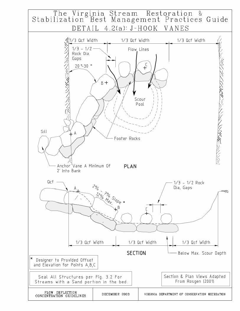


177
PRACTICE 4.3: WING DEFLECTORSIn-stream rock or log structure designed to narrow channels and concentrate low flows
DESCRIPTION
Single or double wing deflectors are installed in the stream channel to provide a narrower base and low flow channel. Thereby, they accelerate normal flows through the constricted section. The deflector provides for improved competence and conveyance of low flows and improves habitat conditions by facilitating upstream deposition and creating scour pools.
APPROPRIATE USES
When channel adjustment processes have produced an overly widened baseflow channel.
When an increase in depth and flow velocity are desired. In straight or riffle sections of predominately gravel/cobble bed streams. In streams with a channel slope of less than 3%. In streams that have adjusted to changes in watershed hydrology to the point where
they exhibit relatively stable plan and profile form but do not have a clearly defined baseflow channel.
Single wing deflectors can be placed in an alternating pattern to initiate meander development.
LIMITATIONS
Deflectors should not be used in streams with large sediment or debris loads. The deflector may cause upstream deposition that can create channel blockages in high sediment load systems.
Deflectors are ineffective in bedrock channels since minimal bed scouring occurs. In addition, streams with sand, silt, or clay beds may not be suited for deflectors because the scour potential in these systems may undercut and destroy the structure.
Single wing deflectors may cause excessive erosion on the opposite streambank. Double wing deflectors may experience excessive erosion of both streambanks up and downstream of the structure. Proper analysis, design and construction can minimize the occurrence of excessive erosion.
DESIGN REQUIREMENTS AND PROCEDURES
The designer should complete a scour depth analysis and ensure that the framing logs or rocks are placed below the design scour depth
No more than 6 inches of the deflector should be above the normal baseflow level.

178
Double wing deflectors are typically designed to reduce the stream width from 25 to 80 percent depending on specific site conditions such as relative bank stability,substrate size, and design flow with associated hydraulic characteristics.
For single deflectors, the distance from the streambank to the tip of the deflector should be no more than 1/2 to 3/4 of the channel bottom width.
For deflectors placed in series, refer to the spacing guidelines given in PRACTICE 3.4: Step Pools.
When placed to initiate meander development, single deflectors should be spaced 5 to 7 Qcf widths apart and arranged on alternating banks.
Deflectors should be placed not to exceed a downstream angle of 30 to 40 degrees with the streambank. The greater the flow velocity, the smaller the angle of deflection.
Triangular deflectors may be constructed with only and “A” and “B” arms (see detail).
MATERIAL SPECIFICATIONS
Logs: 8 inches to 12+ inches in diameter rot-resistant logs. Rock: Footer and vane rocks must be large enough to achieve the design height
and appropriately sized to resist movement due to stream flow characteristics. Rocks shall be relatively rectangular in shape, and uniform in size. Uniform riprap may be used in smaller systems.
Riprap or Coarse Aggregate: Appropriately sized to withstand flow conditions of the stream.
Anchors: 1/4 inch minimum rebar or drift pin for anchoring and connecting logs.Length should be 18 inches at a minimum.
CONSTRUCTION RECOMMENDATIONS
For log deflectors, all logs should be firmly anchored into the streambank a minimum of 5 to 6 feet.
All logs should be anchored into the stream bed to a depth greater than the design scour depth at a spacing of 5 feet on center. A minimum of 3 anchors per log shall be used.
Footer rocks should extend to a depth below the design scour depth. Ensure no leakage/flow under or around the structure by properly grading, sealing,
and compacting under and around the structure. After installation, check proper function/flow path by observing flow over structure.
Repair as needed to ensure proper function. Placement of rock may require a track hoe with a hydraulic thumb. Require an inspection of the rock material before it is placed. Rock size and shape
requirements are specific and often inappropriate material is installed and must be removed or ultimately leads to structural failure.
Reinforce the bank opposite of a single wing deflector as necessary to ensure bank stability.

179
INSTALLATION GUIDELINES
Excavate a trench in the channel bed and toe of bank to a depth below the design scour depth.
Place the footer rocks or logs. Place the arm rocks or logs on top of the footer course. Anchor logs per construction guidelines.
Secure logs 5-6 feet into the banks. Secure rocks a minimum of 1 foot into the banks.
Fill the frame with riprap, coarse aggregate, or salvaged channel material. Pack tightly.
Reinforce the opposite bank for single deflectors and the upstream and downstream bank for double deflectors as needed to prevent excessive erosion.
If riprap is used, it should be designed and constructed per Standard and Specification 3.19 of the Virginia Erosion and Sediment Control Handbook.


181
PRACTICE 4.4: LOG VANESIn-stream wood structure designed to direct near bank erosional forces away from streambank
DESCRIPTION
Log vanes are used to deflect near bank erosional forces away from unstable streambanks and to improve/create aquatic habitat through the formation of scour pools.
APPROPRIATE USES
To deflect erosional forces away from the streambank at the upstream end of the outer mender bend or other unstable areas.
In sand, silt, and clay bed streams or in streams where a design preference for woody material is expressed.
When fish habitat enhancement or flow deflection are desired.
LIMITATIONS
The Qcf height must be accurately located for the stream as the vane is set into the streambank at the Qcf elevation.
Vanes should not be used in stream reaches with channel slopes greater than 3%. Log vanes have limited lengths, so may not be suitable for large rivers. Logs degrade over time and may need to be periodically maintained or replaced.
DESIGN REQUIREMENTS AND PROCEDURES
Log Vanes should intersect the bank at an angle between 20 and 30 degrees. The angle is measured upstream from the tangent line where the vane intercepts the bank. A smaller angle produces a longer arm. A longer arm provides more linear feet of bank protection.
Log Vane slopes are typically 2-15 percent. Slopes are constrained by length of available logs. The steeper the slope of the vane, the less stable it may be.
Specify elevation and offset values for both ends of the vane arms. This ensures exact placement of the structure by the contractor.
Designer must specify a design depth for the scour pool immediately downstream of the log vane. A scour depth analysis is recommended to aid in this effort.
The log vane must terminate at the Qcf elevation. If the top of bank is above Qcf, a Qcf bench must be created. The log vane must be properly connected or entrenched into the bank at the Qcf elevation.

182
MATERIAL SPECIFICATIONS
Logs: 8 inches to 12+ inches in diameter rot-resistant logs. Anchors: 1/4 inch minimum diameter, 3 foot long rebar or drift pins for anchoring
and connecting logs. Support Pilings: 3 inches to 6 inches in diameter logs with one angled and one flat
end. Long enough to extend from the normal baseflow elevation to a minimum of one foot below the design scour depth.
Riprap: Riprap per Standard and Specification 3.19: Riprap of the Virginia Erosion and Sediment Control Handbook for bank armoring and toe protection.
CONSTRUCTION RECOMMENDATIONS
Ensure no leakage/flow under or around the structure by properly grading, sealing, and compacting under and around the structure. After installation, check proper function/flow path by observing flow over structure.
Repair as needed to ensure proper function. The log vane should span a maximum of 1/3 of the Qcf width.
INSTALLATION GUIDELINES
Excavate a trench along the bottom of the stream bed and to the Qcf elevation in the streambank for the log vane. Excavate a Qcf bench if the top of bank is not at the Qcf elevation. The log vane must be properly connected or entrenched into the bank at the Qcf elevation.
Anchor logs into the stream bed to a depth below the design scour depth. Logs should be anchored together with anchor rods at a spacing of 5 feet on center.Place an anchor on both sides of the support piling at the streamside end of the structure.
Place the support piling on the downstream side of the log. The support piling should be driven into the bottom below the anticipated scour depth. Anchor the support piling to the log vane with one anchor per log comprising the vane.
The log vane should extend into the bank a minimum of 5 to 6 feet. Riprap may be needed upstream and downstream of where the log vane enters the bank to enhance stability. If riprap is used, it should be designed and constructed per Standard and Specification 3.19 of the Virginia Erosion and Sediment Control Handbook.
Excavate the scour pools to the design depth.

185
PRACTICE 4.5: CUT-OFF SILLSIn-stream rock or vegetative structure designed to concentrate low flows and accumulate sediment
DESCRIPTION
Cut off sills are installed in the stream channel to provide a narrower base and low flow channel and accumulate sediment behind the sills. The sills function similarly to wing deflectors with the key difference being that the frame formed by the sill is not filled.The sills are designed to build up over time by creating conditions for sediment deposition.
APPROPRIATE USES
When channel adjustment processes have produced an overly widened baseflowchannel and an increase in depth and flow velocity are desired.
In straight or riffle sections of predominately gravel/cobble bed streams. In streams with a channel slope of less than 3%. In streams that have adjusted to changes in watershed hydrology to the point where
they exhibit relatively stable plan and profile form but do not have a clearly defined baseflow channel.
A linear deflector can be used to provide a stable feature to define the edge of the sill.
A vegetative sill can be used for finer bed streams with lower erosional forces.
LIMITATIONS
Sills are ineffective in bedrock channels. Requires a sediment load that will encourage deposition behind the sills. Low
sediment load streams are not suited for cut-off sills.
DESIGN REQUIREMENTS AND PROCEDURES
The designer should complete a scour depth analysis and ensure that sill rocks are placed at a depth below the design scour depth.
No more than 6 inches of the sill should be above the normal baseflow level. The terminal end of the sill should not extend further than 1/2 to 3/4 of the channel
Qcf width. Sills should be placed not exceed a downstream angle of 20 to 30 degrees with the
streambank. The greater the flow velocity, the smaller the angle of deflection.
MATERIAL SPECIFICATIONS
Rock: rocks large enough to achieve the design height and sized to resist movement due to stream flow characteristics. Rocks shall be relatively rectangular in shape, and uniform in size. Uniform riprap may be used in smaller systems.

186
Vegetation: Woven live cuttings or emergent plant material tied together at the base with wire or synthetic twine. See PRACTICE 2.6: Live Stakes for live cuttings specifications. See PRACTICE 2.4: Fascines for additional vegetative specifications. See PRACTICE 2.4: Natural Fiber Roll for synthetic twine specifications. See PRACTICE 2.5: Brush Mattresses for wire specifications
CONSTRUCTION RECOMMENDATIONS
All sill rocks should be placed to a depth below the design scour depth. Extend the sill a minimum of 1 foot into the streambank.
Ensure no leakage/flow under or around the structure by properly grading, sealing, and compacting under and around the structure.
After installation, check proper function/flow path by observing flow over structure. Repair as needed to ensure proper function.
Require an inspection of the rock material before it is placed. Rock size and shape requirements are specific and often inappropriate material is installed and must be removed or ultimately leads to structural failure.
Reinforce the bank opposite of a cut-off sill as necessary to ensure bank stability.
INSTALLATION GUIDELINES
Excavate a trench in the channel bed and toe of bank to a depth below the design scour depth.
Place the sill rocks and anchor into the bank a minimum of 1 foot. Place optional linear deflector if used. Reinforce the opposite bank for single deflectors and the upstream and downstream
bank for double deflectors as needed to prevent excessive erosion.


189
SECTION 5TEMPORARY FLOW DIVERSION GUIDELINES
PRACTICE 5.1. PUMP-AROUND DIVERSION PRACTICE 5.2. SANDBAG/STONE DIVERSION
PRACTICE 5.3. DIVERSION PIPE PRACTICE 5.4. PORTABLE DAMS/BARRIERS
PRACTICE 5.5. TEMPORARY DIVERSION CHANNELS

191
PRACTICE 5.1: PUMP-AROUND DIVERSIONDewatering practice for temporarily pumping flow around segments of the stream channel during construction
DESCRIPTION
This practice involves installing a temporary pump-around system and in-streambarriers to divert flow around sections or reaches of the stream.
APPROPRIATE USES
Where construction activities require that a linear segment of the stream be dewatered and maintained in a dry condition.
When restoration practices (such as PRACTICE 3.1: Rock Cross Vanes) that span the entire width of the stream are installed.
For watersheds less than 1 square mile in size.
LIMITATIONS
Amount of flow capable of being diverted is determined by the capacity of the pump and the height of the in-stream barriers.
Costs are proportional to diversion requirements. Pumps can break down and cause delays.
DESIGN REQUIREMENTS AND PROCEDURES
Pump selection requires the computation of Total Dynamic Head (TDH):TDH = static suction lift + static discharge head + friction loss+ velocity head (Godwin 2003).
Height of in-stream barriers shall be the normal base flow depth + 1 foot of freeboard for pump-around diversions that will be installed and removed in the same workday.
Height of in-stream barriers for a continuous pump-around shall be the 2-year storm elevation + 1 foot of freeboard. The minimum in-stream barrier height is 2 feet.
Always requires a pump with a capacity greater than that required to pump the desired flow.
MATERIAL SPECIFICATIONS
In-stream Barrier: Either riprap per Specification 3.19: Riprap of the Virginia Erosion and Sediment Control Handbook or sandbags. Sandbags may be filled on site or pre-filled and made of burlap or polypropylene materials which are resistant to ultra-violet radiation, tearing, and puncture and should be woven tightly enough to prevent leakage of the fill material (i.e., sand, fine gravel, etc.).
Sheeting: Seamless polyethylene plastic sheeting with a minimum 4-mil thickness impervious and resistant to puncture, tearing and ultraviolet degradation or equivalent.

192
Pumping Equipment: Electric, diesel or gasoline venturi, vacuum, or centrifugal primed pump. Appropriately sized rigid intake and discharge pipe/hose with positive restrained joints. Necessary connectors and properly stored fuel.
Dewatering Structure: Per Standard and Specification 3.26 in the Virginia Erosion and Sediment Control Handbook or sediment/dirt bag per manufacturers specifications.
Velocity Dissipater: Riprap or sandbag lined “plunge pool” sized to be non-erosiveat the discharge pipe velocity.
CONSTRUCTION RECOMMENDATIONS
Sandy material may be used to fill sandbags. If permitted, material from the channel may be used to fill the bags.
The length of stream dewatered should be determined by the amount of work that can be completed in one workday. Continuous pumping adds increased costs and risks of failure and delays.
Where possible, utilize existing pools within the stream in place of an excavated sump-hole.
Strategic placement of the in-stream barrier can eliminate multiple installations during construction.
Remove all large debris located within the foundation of the barrier to ensure proper sealing and reduce leakage through the barrier.
Sandbag/stone barrier should be monitored daily for leakage and repaired as necessary.
INSTALLATION GUIDELINES
Excavate sump hole or identify existing pool upstream of the work area. Install velocity dissipater downstream of the work area. Set up pump and hose/pipe. Install upstream and downstream barriers and start pump. Use de-watering pump and dewatering device to remove water left between the in-
stream barriers after primary pump installation and as needed during construction. Complete in-stream construction activities and remove in-stream barriers. Restore/repair impacted stream areas.


195
PRACTICE 5.2: SANDBAG/STONE DIVERSIONDewatering practice for temporarily diverting stream flow around a portion of a stream’s width during construction
DESCRIPTION
This practice involves installing a barrier in a portion of the stream channel for the purpose of diverting flow around an area of the stream to provide dry conditions during construction.
APPROPRIATE USES
When installation of stream practices requires diverting flow around an area of the streambank and a portion of the stream bed to maintain workable conditions.
To enhance construction conditions to repair small, localized areas of bank failure or implement bank stabilization/protection measures.
LIMITATIONS
Results in smaller area of stream access compared to other temporary in-streamconstruction methods.
May fail and erode during storm events. For large channels, PRACTICE 5.4:Portable Dams/Barriers may be more suitable.
DESIGN REQUIREMENTS AND PROCEDURES
Height of in-stream barriers shall be the normal base flow depth + 1 foot of freeboard.
In-stream barrier shall not be greater than 55% of the stream bottom width. De-watering pump must be diverted through a dewatering structure per Standard
and Specification 3.26 in the Virginia Erosion and Sediment Control Handbook.
MATERIAL SPECIFICATIONS
In-stream Barrier: Either riprap per Standard and Specification 3.19: Riprap of the Virginia Erosion and Sediment Control Handbook or sandbags. Sandbags may be filled on site or pre-filled and made of burlap or polypropylene materials which are resistant to ultra-violet radiation, tearing, and puncture and should be woven tightly enough to prevent leakage of the fill material (i.e., sand, fine gravel, etc.).
Sheeting: Seamless polyethylene plastic sheeting with a minimum 4-mil thickness impervious and resistant to puncture, tearing and ultraviolet degradation or equivalent.
Pumping Equipment: (As needed) Electric, diesel or gasoline venturi, vacuum, or centrifugal primed pump. Appropriately sized rigid intake and discharge pipe/hose with positive restrained joints. Necessary connectors and properly stored fuel.

196
Dewatering Structure: (As needed) Per Standard and Specification 3.26 in the Virginia Erosion and Sediment Control Handbook or sediment/dirt bag per manufacturers specifications.
CONSTRUCTION RECOMMENDATIONS
Sandbag/stone barrier should be monitored daily for leakage and repaired as necessary.
Remove all large debris located within the foundation to ensure proper sealing and reduce leakage through the barrier.
In-stream barrier should extend upstream and downstream of the area to be disturbed so its placement does not interfere with in-stream construction.
Sandy material should be used to fill sandbags. If permitted, material from the channel may be used to fill the bags.
The length of stream dewatered should be determined by the amount of work that can be completed in one workday.
INSTALLATION GUIDELINES
The diversion structure should be installed from upstream to downstream. Use de-watering pump and dewatering device to remove water left between the in-
stream barriers after installation and as needed during construction. Complete in-stream construction activities and remove in-stream barriers. Restore/repair impacted stream areas.


199
PRACTICE 5.3: DIVERSION PIPESDewatering practice for temporarily diverting flow into a pipe through a segment of the stream during construction
DESCRIPTION
This practice consists of installing and removing stream flow diversion pipes in combination with sandbag or stone barriers when construction activities occur across the width of the stream.
APPROPRIATE USES
Where construction activities require that a reach of the stream be dewatered and maintained in a dry condition.
When restoration practices that span the entire width of the stream are installed. When the flow required to be diverted can be accomplished without pumping. For watersheds less than 1 square mile in area.
LIMITATIONS
Diversion pipes can only be used for a maximum drainage area of 1 square mile. Diversion pipes may reduce equipment access and maneuverability to in-stream
work area because pipes may rest on the channel bottom. Placing cover over the pipe may improve work conditions.
Difficult to use for grade control structures which span the entire channel, After installation, apparatus is difficult to adjust or move without completely
removing.
DESIGN REQUIREMENTS AND PROCEDURES
Requires a positive slope to allow flow through pipes. Size pipe diameter to allow for greater than required flow capacity. The pipe should
be sized to a 2-year storm if it is to be in place for less than 14 days (refer to Table 3.24A in the Virginia Erosion and Sediment Control Handbook).
Multiple pipes can be used for greater flow capacity, but may take up too much space in the de-watered work area.
Height of instream barriers should be the normal base flow depth + a minimum of 1 foot of freeboard for sandbag/stone diversions that will be installed and removed in the same workday. The minimum instream barrier height is 2 feet.

200
MATERIAL SPECIFICATIONS
Pipes: High Density Polyethylene Pipe (HDPE) or equivalent of appropriate thickness and diameter to accomplish diversion of stream flow. The pipe shall extend a minimum of one foot beyond the upstream and downstream toes of the barriers.
In-stream Barrier: Either riprap per Standard and Specification 3.19: Riprap of the Virginia Erosion and Sediment Control Handbook or sandbags. Sandbags may be filled on site or pre-filled and made of burlap or polypropylene materials which are resistant to ultra-violet radiation, tearing, and puncture and should be woven tightly enough to prevent leakage of the fill material (i.e., sand, fine gravel, etc.).
Sheeting: Seamless polyethylene plastic sheeting with a minimum 4-mil thickness impervious and resistant to puncture, tearing and ultraviolet degradation or equivalent.
Pumping Equipment: (As needed) Electric, diesel or gasoline venturi, vacuum, or centrifugal primed pump. Appropriately sized rigid intake and discharge pipe/hose with positive restrained joints. Necessary connectors and properly stored fuel.
Dewatering Structure: (As needed) Per Standard and Specification 3.26 in the Virginia Erosion and Sediment Control Handbook or sediment/dirt bag per manufacturers specifications.
Filter Fabric: If used for sealing the structure, filter fabric shall consist of a material meeting the requirement for filter fabric used with riprap as detailed in Table 3.19 D in section 3.19 of the Virginia Erosion and Sediment Control Handbook Third Edition, 1992, page III-171. A granular filter may be substituted for or used with filter fabric. See Standard and Specification 3.19: Riprap for granular filter material specifications.
CONSTRUCTION RECOMMENDATIONS
Riprap can be installed on the barriers to maintain the pipe in place. Barrier should be monitored daily for leakage and repaired as necessary. Instream Barrier location should extend beyond (upstream and downstream) area to
be disturbed so its placement does not interfere with in-stream construction. Remove all large debris located within the foundation of the barrier to ensure proper
sealing and reduce leakage through the dike. Sandy material should be used to fill sandbags. Due to stability issues, equipment cannot be driven over pipes. If there is a
possibility of the pipes being driven over by construction equipment, at least 12 inches of stone needs to be placed around the pipe.

201
INSTALLATION GUIDELINES
Install upstream and downstream in-stream barriers and pipe. Use dewatering pump and dewatering device to remove water left between the in-
stream barriers after installation and as needed during construction. The invert elevation of the pipe should be installed on the natural streambed grade
per Standard and Specification 3.24: Temporary Vehicular Stream Crossing in theVirginia Erosion and Sediment Control Handbook.
Filter fabric or stone shall be placed under the pipe and should extend one-footbeyond the pipe. Width of filter fabric or stone used under the pipe should be sized according to Standard and Specification 3.24: Temporary Vehicular Stream Crossing in the Virginia Erosion and Sediment Control Handbook.
Complete in-stream construction activities and remove in-stream barriers. Restore/repair impacted stream areas.


203
PRACTICE 5.4: PORTABLE DAMS/BARRIERSMeasures and materials for creating easily moved in-stream barriers to control stream flow
DESCRIPTION
This practice consists of installing portable stream flow barriers to allow for de-watering of a work area within a stream channel or lake.
APPROPRIATE USES
For use in larger rivers, lakes or along shorelines. Can be used for water depths of 7+ feet.
As an alternative to stone and sandbag barriers, based on material availability. When specific conditions of the dewatering site encourage the use of
alternatives to stone and sandbags as barriers.
LIMITATIONS
Apparatus may be difficult to adjust or move when properly installed.
DESIGN REQUIREMENTS AND PROCEDURES
Height of in-stream barriers shall be the normal base flow depth + 1 foot of freeboard for diversions that will be installed and removed in the same workday.
Height of in-stream barriers for a continuous pump around shall be the 2-yearstorm elevation + 1 foot of freeboard. The minimum in-stream barrier height is 2 feet.
MATERIAL SPECIFICATIONS
Modular dams: shall consist of self-contained impermeable containers per manufacturers specifications filled with sand.
Jersey Wall Barrier: shall consist of concrete jersey wall barriers per manufacturers specifications covered with polyethylene sheeting.
Inflatable dams: shall consist of self-contained impermeable dams per manufacturers specifications filled with water.
Sheeting: Seamless polyethylene plastic sheeting with a minimum 4-milthickness impervious and resistant to puncture, tearing and ultraviolet degradation or equivalent.
Pumping Equipment: (As needed) Electric, diesel or gasoline venturi, vacuum, or centrifugal primed pump. Appropriately sized rigid intake and discharge pipe/hose with positive restrained joints. Necessary connectors and properly stored fuel.

204
Dewatering Structure: (As needed) Per Standard and Specification 3.26 in the Virginia Erosion and Sediment Control Handbook or sediment/dirt bag per manufacturers specifications.
CONSTRUCTION RECOMMENDATIONS
Dams/barriers shall be installed before any work is done in the stream channel. Dams/barriers should be monitored daily for leakage and repaired as
necessary. Dam locations should extend beyond (upstream and downstream) area to be
disturbed so its placement does not interfere with in-stream construction. A de-watering pump is required to handle seepage. Remove all large debris located within the foundation of the barrier to ensure
proper sealing and reduce leakage through the barrier.
INSTALLATION GUIDELINES
Refer to detail 5.4 (a) through 5.4(c) for installation guidelines. Complete in-stream construction activities and remove in-stream barriers. Restore/repair impacted stream areas.


209
PRACTICE 5.5: TEMPORARY FLOW DIVERSIONDewatering practice for temporarily diverting flow around a segment of the stream during construction
DESCRIPTION
This practice consists of installing and removing a temporary diversion channel around an area of the stream to provide dry conditions during construction.
APPROPRIATE USES
Where stream restoration construction activities require that a linear segment of the stream be dewatered and maintained in a dry condition.
When stream restoration practices (such as PRACTICE 3.1: Rock Cross Vanes) that span the entire width of the stream are installed.
When the flow required to be diverted can be accomplished without pumping.
LIMITATIONS
Diversion channel cannot easily be adjusted or moved when properly installed.
Diversion channel may reduce equipment access and maneuverability to in-stream work area.
May not be practical in large channels.
DESIGN REQUIREMENTS AND PROCEDURES
Requires a positive slope to allow flow through channel. Requires a sufficient area to construct the diversion channel. Refer to the latest Virginia Department of Transportation Road and Bridge
Standards, Volume I (TD-CL, section 113.01) for proper construction and materials.
MATERIAL SPECIFICATIONS
Refer to the latest Virginia Department of Transportation Road and Bridge Standards, Volume I (TD-CL, section 113.01) for proper material specifications.
CONSTRUCTION RECOMMENDATIONS
Bottom width of temporary diversion channel shall approximate the bottom width of the natural stream channel.
Once started, any work to relocate a stream (plugs) shall not be discontinued until it is completed.

210
Linings and barrier should be monitored daily for leakage and repaired as necessary.
INSTALLATION GUIDELINES
The diversion structure should be installed from upstream to downstream. Complete in-stream construction activities and remove in-stream barriers. Restore/repair impacted stream areas. Follow the “General Notes” for standard TD-CL located within The Virginia
Department of Transportation Road and Bridge Standards, Volume I.
Standard TD-CL (TEMPORARY DIVERSION CHANNEL & ACCEPTABLE LININGS) is included on the following page for reference purposes. This Standard is excerpted from The Virginia Department of Transportation, Road andBridge Standards, Volume 1 (page 113.01).


I
APPENDIX

III
Glossary
Aggradation: The geologic process by which a streambed is raised in elevation by the deposition of additional material transported from upstream (opposite of degradation).
Alluvial stream: Streams that have erodible boundaries and are free to adjust dimensions, shape, pattern and gradient in response to change in slope, sediment supply or discharge.
Alluvium: Sedimentary deposits created by streams on river beds, floodplains and as alluvial fans. The term applies to stream deposits of recent time.
Anastomosing channel: A channel that is divided into several smaller channels, which successively meet and then redivide.
Avulsion: A significant and abrupt change in channel alignment resulting in a new channel across the floodplain.
Bankfull discharge: A flow of water large enough to fill the width and depth of a stable, alluvial stream. Water fills the channel up to the first flat depositional surface (active floodplain) in the stream. Such a discharge typically occurs every 1.5 years or so.
Baseflow: Flow in a channel generated by moisture in the soil or groundwater.
Batter: The receding, upward slope of a wall or the face of a structure. To give a structure or wall a receding, upward slope.
Bed: The part of a channel below the ordinary high water lines of state waters.
Bed erosion: The process by which water loosens and wars away soil and rock from the bottom of a body of water, usually resulting in a deepening of the body of water.
Bedload: The part of a channel’s sediment transport that is not in suspension, consisting of coarse material that is moving on or near the channel bed.
Bioengineering: An engineering technique that applies biological knowledge when designing and constructing earth and water constructions and when dealing with unstable slopes and streambanks.
Braided channel: A river channel having multiple subchannels that meander away from each other and then reunite at intervals.

IV
Coir: Coconut fiber used in a variety of ways to protect streambanks from erosion.
Colluvium: A general term for loose deposits of soil and rock moved by gravity; e.g. talus.
Competence: The maximum size of particle that a stream can carry. This is governed by water velocity.
Cross section: The characteristics of an object when viewed crosswise; for streams, a transect taken at right angles to flow direction.
D50,/D100: The particle size for which 50 and 100 percent of the sample is finer.
Degradation: The removal of streambed materials caused by the erosional force of water flow that results in a lowering of the bed elevation throughout the reach (opposite of aggradation).
Deposition: The settlement of material onto the channel bed.
Discharge: The rate of flow expressed in volume per unit of time. For example, cubic feet per second. Discharge is the product of the mean velocity and the cross-sectional area of flow.
Dominant discharge: The discharge that has the greatest impact on the channelboundaries. In theory, maintaining the dominant discharge continuously in the channel would result in the same channel boundary configuration that would form from the fluctuations of natural hydrologic occurrences. This discharge is responsible for the largest volume of sediment transport over a long period of record. It is typically a one- to three-year event.
Effective discharge: The single discharge event that transports the largest volume of sediment. This discharge is determined by combining graphical representations of flow duration and sediment transport for each interval.
Erosion: A process or group of processes whereby surface soil and rock is loosened, dissolved, or worn away and moved from one place to another by natural processes. Erosion usually involves relatively small amounts of material at a time; but, over a long period of time, it can involve very large volumes of material.
Fascine: A long bundle of live cuttings bound together and secured to the streambank or floodplain with live and dead stakes.
Floodplain: Any lowland that borders a stream and is inundated periodically by the stream’s waters.

V
Fluvial geomorphology: The science of or pertaining to river processes. Also, the distinctive channel features produced by the action of a stream or river.
Grade Controls: Hard points in the bed of a channel which hold a set elevation in the longitudinal profile. Can be natural features such as rock outcrops or large boulder deposits, or manmade features of riprap, concrete, etc. which resist erosion and head cut migrations.
Headcuts: The erosion of the channel bed, progressing in an upstream direction, recognized as small drops or waterfalls or abnormally over-steepened channel segments.
Hydraulic gradient: (a) The slope of the water surface. (b) The drop in pressure head per length in the direction of stream flow.
Hydraulic radius: The cross-sectional area of a stream divided by the wetted perimeter.
Hydrology: The properties, distribution and circulation of water in a stream channel.
Imbricated: Overlapping, as shingles or tiles on a roof.
Incised: Cut down into or entrenched.
Incised channel: A stream channel that has deepened, becoming disconnected from its floodplain.
Incision: The change in channel cross section resulting from the process of degradation.
Manning’s n: An empirical coefficient for computing stream bottom roughness used in determining water velocity in stream discharge calculations.
Meander: The snake-like appearance of the reach of a stream. More specifically, a stream reach is said to be meandering if its length is 1.5 times (or more) the length of the valley through which it passes. Any reach that exceeds the length of the valley can be taken as evidence of meandering, but 1.5 is the standard minimum used to confirm meandering activity.
Meander width: Measure of projected distance between outer banks of two successive meanders in a channel.
Planform: The characteristics of a river as viewed from above (in an aerial photo, on a map, etc.), which are generally expressed in terms of pattern, sinuosity

VI
(channel length/valley length) and individual meander attributes such as amplitude, wavelength and radius of curvature.
Point bar: A stream depositional feature, usually found on the side opposite the concave bank, that helps move bedload from one meander to the next.
Qcf: (also Qcf) The channel-forming discharge; Qcf is a theoretical discharge which is responsible for shaping and maintaining the morphology of a dynamically stable alluvial stream.
Recurrence interval: Expected or observed time intervals between hydrological events of a particular magnitude described by stochastic or probabilistic models (log-log plots). Also called “return period.”
Revetment: Bank protection accomplished by armoring the bank with erosion-resistant material.
Riffle: A reach of stream in which the water flow is more shallow and more rapid than the reaches above and below; natural streams often consist of a succession of pools and riffles.
Riprap: Large, durable materials (usually rocks, sometimes broken concrete, etc.) used to protect a streambank from erosion; also refers to the materials used for this purpose.
Riparian: The area adjacent to flowing water (e.g., rivers, perennial or intermittentstreams, seeps or springs) that contains elements of both aquatic and terrestrial ecosystems
Riparian buffer: A swath of riparian vegetation along a channel bank that provides some measure of protection from the erosive forces of water along thechannel margins.
Rock toe: A structure composed of rock materials, installed at the base of a bank slope to protect the base of the bank from the erosive forces of stream flow.
Rootwad: The root mass of a tree.
Scour: The process of removing material from the bed or banks of a channel through the erosive action of flowing water.
Sediment: Any mineral or organic matter of any size in a stream channel.
Sediment load: the sum total of sediment available for movement in a stream, whether in suspension (suspended load) or at the bottom (bedload).

VII
Shear stress: A measure of the erosive force acting on and parallel to the channel boundary. It is expressed as force per unit area (lb/ft2). In a channel, shear stress is created by water flowing parallel to the boundaries of the channel; bank shear is a combined function of the flow magnitude and duration, as well as the shape of the bend and channel cross section.
Stream power: The rate of doing work, or a measure of the energy available for moving rock, sediment particles, or woody or other debris in the stream channel, as determined by discharge, water surface slope, and the specific weight of water.
Sinuosity: The ration of stream-channel length, measured in the thalweg from the top of the valley to the bottom of the valley, or ratio of the valley slope to the channel slope.
Substrate: Mineral and organic material that forms the bed of a stream.
Terrace: A level bench breaking the continuity of a slope, usually a remnant or historic floodplain surface.
Thalweg: The path or thread of main flow, usually follows the deepest path in the stream channel.
Toe erosion: The erosion of particles from the streambank and/or bed which results in the undermining of the toe and subsequent gravity collapse or sliding of overlying layers.
Watershed: An area of land surface that collects precipitation, draining it into a stream.
Velocity: The distance that water travels in a given direction during a given interval of time.
Selected References
Washington State Aquatic Habitat Guidance program. Integrated Streambank Protection Guidelines. 2003.
Dave Miller. Inter-Fluve Inc. 2001. White Paper - Channel Design. Submitted to Washington Department of Fish and Wildlife, Department of Ecology and Dept. of Transportation.

VIII
Information resources
1. www.vims.edu/ccrm/wetlands/handbook/: Includes the Virginia Wetlands Management Handbook in .pdf format. This handbook includes the WetlandsGuidelines written by VIMS and VMRC.Subaqueous Guidelines, VMRC.2. Shoreline Development BMPs, VMRC.3. Laws of Virginia Relating to Submerged Lands, Wetlands and Coastal Primary Sand Dunes and Beaches, VMRC.4. Virginia Erosion and Sediment Control Handbook for Standards and Specifications, Virginia Department of Conservation and Recreation (DCR) http://www.dcr.state.va.us.5. Virginia Stormwater Handbook, Virginia Department of Conservation and Recreation (DCR) http://www.dcr.state.va.us.6. Shoreline Management in the Chesapeake Bay, VIMS.7. http://laws.fws.gov: Lists many federal laws with explanations in easy to read language. Virginia Water Protection Permit information can be found at http://www.deq.state.va.us.
Selected Federal Agencies
The mission of the National Oceanographic and Atmospheric Administration (NOAA), an agency within the U.S. Department of Commerce, is to describe and predict changes in the earth’s environment and to conserve and wisely manage the nation’s coastal and marine resources to ensure sustainable economic opportunities. NOAA provides a wide range of observational, assessment, research, and predictive services for estuarine and coastal ocean regions. NOAA has developed an array of programs to address national-scale estuarine issues and specific problems affecting individual estuarine and coastal ocean systems. In partnership with EPA, NOAA implements the Coastal Zone Act Reauthorization Amendments of 1990.
The Natural Resources Conservation Service (NRCS) is responsible for providing conservation planning and technical assistance to prevent soil erosion,improve water quality, and improve and protect natural resources. NRCS works with farmers, city planners, watershed groups, state and local governments, civic organizations, and individual homeowners to provide science-based solutions to environmental concerns. When providing assistance, NRCS focuses on the sound use and management of soil, water, air, plant, and animal resources. Participation in NRCS programs is voluntary, and is based upon the premise that clients will make and implement sound decisions when they understand their resources, natural resource problems and opportunities, and the effects of their decisions.

IX
The U. S. Army Corps of Engineers (COE) is responsible for ensuring adequate flood control, hydropower production, navigation, water supply storage, recreation, and fish and wildlife habitat. The Corps contracts and regulates coastal engineering projects, particularly harbor dredging and beach renourishment projects. They also review and permit coastal development and artificial reefprojects. A joint permit from the Virginia Marine Resources Commission and the Corps of Engineers is required for all dredging projects.
The U.S. Environmental Protection Agency (EPA) is responsible for ensuring that environmental protections are considered in U.S. policies concerning economic growth, energy, transportation, agriculture, industry, international trade, and natural resources; ensuring national efforts to reduce environmental risk are based on the best available scientific information; and providing access to information on ways business, state and local governments, communities, and citizens can prevent pollution and protect human health and the environment. The Office of Water is responsible for implementing, among other laws, the CleanWater Act, portions of the Coastal Zone Act Reauthorization Amendments of 1990, and the Resource Conservation and Recovery Act. Activities are targeted to prevent pollution wherever possible and to reduce risk to people and ecosystems in the most cost effective manner.
The U.S. Fish and Wildlife Service (FWS) mission is working with others to conserve, protect and enhance fish, wildlife and plants and their habitats for the continuing benefit of the American people. The Service enforces Federal wildlife laws, protects endangered species, manages migratory birds, restores nationally significant fisheries, and conserves and restores wildlife habitat such as wetlands.
The U.S. Geological Survey (USGS) a bureau of the Department of the Interior, has the principal responsibility within the Federal government for mapping the Nation, assessing its geologic resources, and providing hydrologic information for appraising the Nation’s water resources. The Virginia District Office is primarily involved in conducting water-resources investigations.

X
Selected State Agencies
The Chesapeake Bay Local Assistance Department (CBLAD) is the state agency that provides support to local governments in carrying out the requirements of the Bay Act. The Bay Act established a cooperative program between state and local government aimed at reducing nonpoint source pollution. The Bay Act Program is designed to improve water quality in the Chesapeake Bay and its tributaries by requiring wise resource management practices in the use anddevelopment of environmentally sensitive land features. At the heart of the Bay Act is the idea that land can be used and developed in ways that minimize impact on water quality. Major Department efforts in implementing the Bay Act include administering a competitive grants program for localities and planning districts, providing training for local government planners and engineers, and reviewing local comprehensive plans and ordinances for compliance.
The Virginia Department of Conservation and Recreation (DCR) enhancesnatural and recreational resources through land management, funding, education and regulation. The main program areas for DCR are State Parks, Natural Heritage, Soil and Water Conservation, Dam Safety and Recreational Planning. In particular is the statewide responsibility for erosion and sediment control (implemented through local ordinance) and stormwater management.
The Virginia Department of Environmental Quality (DEQ) administers the requirements of many federal laws and programs. The Virginia Water Protection Program is responsible for the administration of the water quality programs delegated to the Commonwealth under the Clean Water Act and as required by the State Water Control Law. Under both State and Federal Law, the Departmentfunctions as the principal water quality management agency within the Commonwealth of Virginia. The goal of the Virginia Water Protection Program is to ensure the protection of the beneficial uses of State waters including nontidal wetlands, prevent degradation of valuable water resources, and work toward the restoration of waters whose quality has been degraded. The Department issues permits for all activities that may result in the physical, biological or chemical alteration of State waters.
The Virginia Department of Forestry (DOF) assists non-industrial, private landowners with forest protection, land conservation, forest health, and resource management issues. Program areas include development of Stewardship Plans, inspection of silvicultural operations for compliance with water quality laws, technical assistance with riparian restoration and reforestation, and forestry research.
The Virginia Department of Game and Inland Fisheries (DGIF) is responsible for management and regulatory jurisdiction of the Commonwealth’s wildlife and freshwater fisheries resources including state and federal endangered and

XI
threatened species. They also provide environmental analysis of projects or permit applications coordinated through the Department of Environmental Quality, Marine Resource Commission and the Corps of Engineers.
The Virginia Marine Resources Commission (VMRC) serves the citizenry of the Commonwealth of Virginia by combining a public interest review process with effective management, regulation and protection of the State’s marine fisheries, submerged lands (state wide) and coastal resources (tidal wetlands and coastal sand dunes/beaches). It is the goal of the Commission’s Habitat Management division to act as stewards of the Commonwealth’s submerged lands and ensure the protection and wise use of these coastal lands and natural resources through the implementation of a regulatory review process and permitting program.
Contact Information
Areas of responsibility – State Organizations
Chesapeake Bay (Protection, Program Status)Alliance for the Chesapeake Bay (804) 775-0951Chesapeake Bay Foundation (804) 780-1392Department of Environmental Quality (800) 592-5482
Chesapeake Bay Preservation Act (Technical Assistance)Chesapeake Bay Local Assistance Department (800) 243-7229Planning/Zoning Office Contact locality
Coastal ResourcesDepartment of Conservation and Recreation (804) 786-2064Department of Environmental Quality, Coastal Program (800) 592-5428Marine Resources Commission (Habitat Management) (804) 247-2200
Conservation of Natural ResourcesDepartment of Conservation and Recreation (804) 786-2064Virginia Association of Soil and Water Conservation Districts (804) 371-2356

XII
Endangered SpeciesDepartment of Conservation and Recreation
Division of Natural Heritage (804) 786-7951Department of Game and Inland Fisheries (804) 367-1000
Environmental LegislationLegislative Services, Virginia General Assembly (804) 786-6530
Erosion and Sediment Control and Stormwater ManagementPlanning/Zoning Office (Codes & Enforcement) Contact localityDepartment of Conservation and Recreation
Division of Soil and Water Conservation (804) 786-2064
Native PlantsDepartment of Conservation and RecreationDivision of Natural Heritage (804) 786-7951Virginia Native Plant Society (703) 672-3814
Polluted Runoff (Nonpoint Source Pollution)Department of Conservation & Recreation
Division of Soil & Water Conservation (804) 786-2064
Preservation of Estuarine HabitatsChesapeake Bay National Estuarine Research Reserve in VA(804) 684-7135Department of Conservation and Recreation
Division of Natural Heritage (804) 786-7951
Preservation of Rare/Unique HabitatsDepartment of Conservation and Recreation
Division of Natural Heritage (804) 786-7951The Nature Conservancy, Virginia Chapter (804) 295-6106
River/Stream PollutionDepartment of Environmental Quality (800) 592-5482

XIII
Shoreline Erosion & StabilizationDepartment of Conservation & Recreation
Division of Soil & Water Conservation (804) 786-2064Virginia Institute of Marine Science Wetlands Section (804) 642-7108
Wetlands (Preservation, Regulations)Chesapeake Bay Local Assistance Department (800) 243-7229Marine Resources Commission (757) 247-2200Virginia Institute of Marine Science: Wetlands Section (804) 642-7108Local Wetlands Board See list below
State Contacts
Chesapeake Bay Local Assistance DepartmentJames Monroe Building101 North 14th Street, 17th FloorRichmond, VA 23219(804) 225-3440 or (800) 243-7229Fax: (804) 225-3447http://www.cblad.state.va.us/
Virginia Department of Conservation and Recreation203 Governor Street, Suite 206Richmond, VA 23219-2094(804) 786-2064Fax: (804) 786-1798http://www.dcr.state.va.us
Virginia Department of Environmental Quality629 East Main Street, Richmond, Va. 23219P.O. Box 10009, Richmond, Va. 23240(804) 698-4000 or toll-free in Virginia, 1-800-592-5482Fax: (804) 698-4319http://www.deq.state.va.us
Virginia Department of Forestry900 Natural Resources DriveSuite 800Charlottesville, VA 22903434-977-6555Fax: (434) 296-2369http://www.vdof.org

XIV
Virginia Department of Game and Inland Fisheries4010 West Broad StreetRichmond, VA 23230(804) 367-1000http://www.dgif.state.va.us/
Virginia Institute of Marine ScienceWetlands SectionRt. 1208 Greate Rd.Gloucester Point, VA 23062(804) 642-7108Fax: (804) 684-7097http://www.vims.edu
Virginia Marine Resources Commission2600 Washington AvenueNewport News, VA 23607-0756(757) 247-2200http://www.mrc.state.va.us
Federal Contacts
Army Corps of EngineersNorfolk District 803 Front Street Norfolk, VA 23510-1096(757) 441-7500http://www.usace.army.mil/
Chesapeake Bay National Estuarine Research Reserve in VirginiaVirginia Institute of Marine ScienceRt. 1208 Greate Rd.Gloucester Point, VA 23062(804) 684-7135Fax: (804) 684-7120http://www.vims.edu/cbnerr
Natural Resources Conservation Service1606 Santa Rosa Road, Suite 209Richmond, VA 23229-5014(804) 287-1691Fax: (804) 287-1736http://www.va.nrcs.usda.gov

XV
U.S. Environmental Protection AgencyU.S. Environmental Protection AgencyRegion III, Office of External Affairs841 Chestnut BuildingPhiladelphia, PA 19107(215) 597-9076http://www.epa.gov/
Chesapeake Bay Program410 Severn Ave, #109Annapolis, MD 214031-800-968-7229http://www.chesapeakebay.net
US Fish and Wildlife ServiceRegional Office300 Westgate Center DriveHadley, MA 01035-9589(413) 253-8200Fax: (413) 253-8308http://www.fws.gov/
US Geological SurveyU.S. Geological SurveyWater Resources of Virginia1730 East Parham RoadRichmond, Virginia 23228(804) 261-2600Fax: (804) 261-2659http://www.usgs.gov
Non-profit groups
Alliance for the Chesapeake BayBayScapes ProgramP.O. Box 1981Richmond, VA 23218(804) 775-0951Fax: (804) 775-0954http://www.alliancechesbay.org

XVI
AudubonNational Audubon Society 700 Broadway New York, NY 10003(212) 979-3000Fax: (212) 979-3188http://www.audubon.org/
Chesapeake Bay FoundationPhillip Merrill Environmental Center6 Herndon AvenueAnnapolis, MD 21403(410) 268-8833http://www.cbf.org
Izaak Walton League707 Conservation LaneGaithersburg, MD 20878(800) 453-5463Fax: (301) 548-0416http://www.iwla.org/
Ocean Conservancy1725 DeSales Street, Suite 600Washington, DC 20036(202) 429-5609Fax: (202) 872-0619http://www.oceanconservancy.org
Sierra Club85 Second Street, Second Floor
San Francisco CA, 94105-3441 (415) 977-5500
Fax: (415) 977-5799http://www.sierraclub.org/

XVII
Local Wetlands Boards (Tidewater, Virginia)
Accomack County (757) 787-5721Cape Charles County (757) 331-3259Charles City County (804) 829-9217Chesapeake (804) 547-6248Colonial Heights (804) 520-9275Essex County (804) 443-4951Fairfax County (703) 324-1210Fredericksburg (540) 372-1179Gloucester County (804) 693-4040Hampton (757) 727-6142Hopewell (804) 541-2267Isle of Wight (804) 357-3191James City County (804) 253-6622King George County (804) 775-7111King William County (804) 769-4927Lancaster County (804) 462-5220Mathews County (804) 725-5025Middlesex County (804) 758-4305New Kent County (804) 966-9861Newport News (757) 247-8437Norfolk (757) 441-2152Northampton County (804) 678-5872Northumberland County (804) 580-8910Poquoson (757) 868-7151Portsmouth (757) 393-8836Prince William County (804) 335-6830Richmond County (804) 333-3415Stafford County (804) 659-8668Suffolk (757) 934-3111Surry County (804) 294-5210Virginia Beach (757) 426-5790Westmoreland County (804) 493-0121West Point (804) 843-3330Williamsburg (757) 220-6130York County (757) 890-3538