THE VIERENDEEL TRUSS: PAST AND PRESENT OF AN …
19
v.15 n.1 2019 DOI: 10.4013/arq.2019.151.11 THE VIERENDEEL TRUSS: PAST AND PRESENT OF AN INNOVATIVE TYPOLOGY A VIGA VIERENDEEL: PASSADO E PRESENTE DE UMA TIPOLOGIA INOVADORA Josep Maria Pons-Poblet 1 Abstract In the late 19th century, Belgian engineer Jules Arthur Vierendeel registered the patent for a new type of beam. This would be later on better known as the Vierendeel truss. It is characterized by the frame’s lack of diagonal members, something which would appear to contradict conditions of steadiness and balance, along with its notable deformation and difficult calculation, caused technicians in his time to be skeptical about its applicability. Nevertheless, its application surged in popularity during the 20th century, being used both in civil engineering and architecture. What are the advantages of the Vierendeel truss as compared to other types, such as diagonal trusses? In this article, the Vierendeel typology will be introduced along with its main features, its calculation as well as its implementation in civil engineering and architectural works. Keywords: Vierendeel, Pratt, statistically indeterminate structures. Resumo No final do século XIX, o engenheiro belga Jules Arthur Vierendeel registou a patente de um novo tipo de viga. Isto seria mais tarde mais conhecido como a armação de Vierendeel. Caracteriza-se pela falta de elementos diagonais do quadro, algo que pareceria contradizer as condições de estabilidade e equilíbrio, juntamente com a sua notável deformação e difícil cálculo, fez com que os técnicos de sua época fossem céticos quanto à sua aplicabilidade. No entanto, sua aplicação cresceu em popularidade durante o século XX, sendo utilizada tanto na engenharia civil quanto na arquitetura. Quais são as vantagens da treliça de Vierendeel em relação a outros tipos, como as treliças diagonais? Neste artigo, a tipologia Vierendeel será introduzida juntamente com suas principais características, seu cálculo e sua implementação em obras de engenharia civil e arquitetura. Palavras-chave: Vierendeel, Pratt, estruturas estatiscamente indeterminadas. 1 Universitat Politècnica de Catalunya, [email protected]
Transcript of THE VIERENDEEL TRUSS: PAST AND PRESENT OF AN …

v.15 n.1 2019
DOI: 10.4013/arq.2019.151.11
THE VIERENDEEL TRUSS: PAST AND PRESENT OF AN INNOVATIVE TYPOLOGY
A VIGA VIERENDEEL: PASSADO E PRESENTE DE UMA TIPOLOGIA INOVADORA
Josep Maria Pons-Poblet1
Abstract
In the late 19th century, Belgian engineer Jules Arthur Vierendeel registered the patent for a new type of beam. This would be later on better known as the Vierendeel truss. It is
characterized by the frame’s lack of diagonal members, something which would appear to contradict conditions of steadiness and balance, along with its notable deformation and difficult calculation, caused technicians in his time to be skeptical about its applicability.
Nevertheless, its application surged in popularity during the 20th century, being used both in civil engineering and architecture. What are the advantages of the Vierendeel truss as
compared to other types, such as diagonal trusses? In this article, the Vierendeel typology will be introduced along with its main features, its calculation as well as its implementation in
civil engineering and architectural works.
Keywords: Vierendeel, Pratt, statistically indeterminate structures.
Resumo
No final do século XIX, o engenheiro belga Jules Arthur Vierendeel registou a patente de um novo tipo de viga. Isto seria mais tarde mais conhecido como a armação de Vierendeel. Caracteriza-se pela falta de elementos diagonais do quadro, algo que pareceria contradizer
as condições de estabilidade e equilíbrio, juntamente com a sua notável deformação e difícil cálculo, fez com que os técnicos de sua época fossem céticos quanto à sua aplicabilidade.
No entanto, sua aplicação cresceu em popularidade durante o século XX, sendo utilizada tanto na engenharia civil quanto na arquitetura. Quais são as vantagens da treliça de
Vierendeel em relação a outros tipos, como as treliças diagonais? Neste artigo, a tipologia Vierendeel será introduzida juntamente com suas principais características, seu cálculo e
sua implementação em obras de engenharia civil e arquitetura.
Palavras-chave: Vierendeel, Pratt, estruturas estatiscamente indeterminadas.
1 Universitat Politècnica de Catalunya, [email protected]

Josep Maria Pons-Poblet THE VIERENDEEL TRUSS
ArquiteturaRevista, v.15, n.1, jan/jun, 2019 194
THE VIERENDEEL TRUSS In May 1897 a Belgian engineer registered the patent for a lattice truss without diagonal lines but rather organized using only vertical and horizontal members. This structure would end up being known as the Vierendeel truss, honoring this Belgian engineer: Jules Arthur Vierendeel (1852–1940).
Figure 1: Outline of the Vierendeel type.
This new type of truss constituted a true novelty when compared to existing beam types. Among several others, the most prominent were the Pratt i , Howeii, and Warreniii beams, each one with specific features of their own.
Figure 2: Outline of the Pratt typology.
Figure 3: Outline of the Warren and Howe typologies.
As can be noted, the Vierendeel type dispensed with diagonal lines, which, working with traction (Pratt), compression (Howe), compression-traction (Warren) doubled as bracing elements of the frame. This was at the origin of an important debate around the Vierendeel truss’s suitability as there were concerns about its structural safety, and it showed greater deformation when compared to the other models. In addition to these items of discussion, the subject of its calculation came up, which couldn’t be tackled using the classic procedures of statics.

Josep Maria Pons-Poblet THE VIERENDEEL TRUSS
ArquiteturaRevista, v.15, n.1, jan/jun, 2019 195
A SIDE NOTE: ISOSTATIC STRUCTURE VERSUS HYPERSTATIC STRUCTURE
Isostatic structures
Statistically determinate structures. They are defined by having three unknowns to be solved.
Figure 4: Outline of an isostatic beam with tree unknowns.
Applying the Rouché-Frobenius (Rouché-Capelli) theorem, we consequently need three independent equations to solve it. These relations are determined by equations of statics, which were perfectly well-known in Vierendeel’s day.
�𝐹𝐹𝑥𝑥 = 0,�𝐹𝐹𝑦𝑦 = 0,�𝑀𝑀𝑧𝑧 = 0
Hyperstatic structures
Statistically indeterminate structures. As opposed to the ones described above, hyperstatic structures present more unknowns than equations. The system, therefore, is compatible but indeterminate. Therein lies the main problem. How are unknowns to be determined if the number of equations is not enough?
Figure 5: Outline of a beam with four unknowns
The expert (whether an architect or an engineer) would have to face a difficult situation. To devise isostatic structures — easy to solve but at the cost of some values, such as the section of the material to be used — or otherwise hyperstatic structures, more desirable from the point of view of design and economy but harder to calculate. In truth, resorting to the classic formulations by Mohr (1835-1918) and Castigliano (1847–1884), among others, was a possibility, but it wouldn’t prevent it from being a really tedious problem.

Josep Maria Pons-Poblet THE VIERENDEEL TRUSS
ArquiteturaRevista, v.15, n.1, jan/jun, 2019 196
An initial examination of the Vierendeel truss allows us to note it is externally isostatic, with its unknowns to be determined being the one corresponding to the pin joint A (Ax and Ay), and its counterpart related to movable joint B (By). Three easily solvable unknowns by using equations of statics.
Figure 6: Example of a Vierendeel beam with loads.
Figure 7: System of resolutive equations of the previous isostatic system.
The problem lies with the determination of stresses in each of its elements, the preliminary step prior to the dimensioning of the structure. This case stops being statically solvable and becomes a hyperstatic problem instead (internally).
As stated previously, a study of the Vierendeel type using the aforementioned hyperstatic methods (Mohr, Castigliano), along with others, such as the integration of the elastics equation, would initiate a process that could turn out to be extremely tedious. As a matter of fact, in general, new formulations should be sought in order to endow the technician with the same accuracy while facilitating the resolution of structures, especially hyperstatic ones. Let’s have a closer look at this interesting part of structures calculation.

Josep Maria Pons-Poblet THE VIERENDEEL TRUSS
ArquiteturaRevista, v.15, n.1, jan/jun, 2019 197
Figure 8: Vierendeel truss. Madrid. (Source: https://cinesdemadrid.blogspot.com/2010_07_11_archive.html )
A first study would take us back in time into 1878, when the calculation of structures has taken a dramatic turn thanks to the essays presented by Benoit Émile Clapeyron (1799–1864) at the Académie des Sciences.
The Frenchman, by means of his Theorem of the three moments, introduced a relatively agile solution for the hyperstatic truss. This new contribution, along with a number of existing solutions, opened a new scenario in the fields of strength of materials and structures theory. In all fairness, the result obtained by Clapeyron is occasionally attributed to Henri Bertot (according to Jacques Heyman), since he penned in 1855 a similar text in the same journal. Nevertheless, a majority of experts attribute the result to Clapeyron. There is no doubt about the enormous importance of the method. It became a staple in the bibliography of university lecturers and professional technicians, as much in Europe as in America at a later point. Starting from this important contribution, the calculation of hyperstatic structures would become greatly simplified.
A closer examination of the Vierendeel truss reveals how it possesses a significant degree of hyperstaticity with parametric states in relation to its degrees of freedom. This further complicated the operative, causing that, even when using Clapeyron’s formulation, its solution remained cumbersome.
Theory of Structures required, once again, to obtain more agile formulations than the existing ones because the increased number of members of the frames, along with their high hyperstaticity, led to a system of resolutive equations, which implied long calculations in order to obtain the desired result. New methods were needed in order to simplify calculations without sacrificing accuracy or safety. In spite of the formulation in some highly useful and rigorous methods (Bendixen-Wilson, 1914; Maney, 1915), only after the early 1930s, a new approach would be discovered in the calculation of structures. This is due to the apparition of an iterative resolution method, which would come to be known as the Cross Method, named after its originator Hardy Cross (1885–1959). His publication (1930) in American Society of Civil Engineers of an article bearing the title Analysis of continuous frames by

Josep Maria Pons-Poblet THE VIERENDEEL TRUSS
ArquiteturaRevista, v.15, n.1, jan/jun, 2019 198
distributing fixed-end moments was a major milestone in the calculation of structures.
Figure 9: American Society of Civil Engineers. (Source: Proceedings of the American Society of Civil Engineers 1930,
https://archives.library.illinois.edu/erec/University%20Archives/1105037/Cross_Analysis_of_Continuous_Frames_opt.pdf )
Hardy Cross himself, in his Synopsis, clearly introduces the aim of his method:
The purpose of this paper is to explain briefly a method which has been found useful in analyzing frames which are statistically indeterminate. The essential idea which the writer wishes to present involves no mathematical relations, except the simplest arithmetic.
The reactions in beams, bents, and arches which are immovably fixed at their ends have been extensively discussed. They can be found comparatively readily by methods which are more or less standard (Cross, 1930).
Once the method had been formulated, it found widespread acceptance both in scholar and technical works, as well as in calculation reports, as the literature on the subject illustrates (Eaton, 2006). Most existing methods were displaced by this one, it being much more nimble, faster, and providing the same security in the end result.
VIERENDEEL TRUSS CALCULATION As it has been previously said, criticism by detractors of the Vierendeel truss originally focused on its calculation. Compared to other typologies, it actually appeared to be a lot more complicated. We were referring to the Pratt truss (or any of the others), which is also widely used in civil engineering. It is commonly accepted in the case of these typologies to calculate (on a first

Josep Maria Pons-Poblet THE VIERENDEEL TRUSS
ArquiteturaRevista, v.15, n.1, jan/jun, 2019 199
instance) considering them as a hinge joint, which proves, consequently, that the equations of statics are perfectly applicable in order to obtain the results very swiftly. These can be subsequently used to dimension the beam or to verify its various components.
Figure 10: Solution of a Pratt truss.
This simplification can’t be applied to the Vierendeel truss since we begin with the premise of a rigid joint and, therefore, the existence of a bending moment M, as well as its corresponding axial force N and shear force T which cannot be taken out of the calculation. This is a consequence of the rigid joint, which ensures the overall stability, and is affected by the lack of diagonal elements, diagonals being precisely what makes calculations notably more difficult. The introduction of the Cross method simplified the problem to a great extent.
Figure 11: Efforts considered in a generic section of a Vierendeel truss.
TWO NEW PROBLEMS... THE BENDING MOMENT AND DEFORMATION Once the problem of calculation of the Vierendeel typology has been partially solved thanks to the Cross method, two more problems of utmost importance ensue: the distribution of the bending moment and the structural deflection.
Let us compare a generic Vierendeel typology (Fig. 12) with a truss of comparable features (Fig. 13).

Josep Maria Pons-Poblet THE VIERENDEEL TRUSS
ArquiteturaRevista, v.15, n.1, jan/jun, 2019 200
Figure 12: Example of a Vierendeel truss with punctual load distribution.
Figure 13: Example of a Pratt truss with punctual load distribution.
In the case of Bending Moments, the Vierendeel typology provides significantly superior values (Fig. 14) as compared to those obtained by the Pratt typology (Fig. 15). This fact has notable effects in the proposed pre-dimensioning or dimensioning solution. Merely as a side note, it should be noted that, if the previous structure had been solved using L50·5 angulars and two-meter tracts, the Vierendeel typology would display the values shown on the indicated figures.
Figure 14: Distribution of bending moments in a Vierendeel typology.
Figure 15: Distribution of bending moments in a Pratt typology.

Josep Maria Pons-Poblet THE VIERENDEEL TRUSS
ArquiteturaRevista, v.15, n.1, jan/jun, 2019 201
On the other hand, the lack of diagonals also conditioned the structure’s deformation. These, acting as propping elements, allowed the structure to deform less, minimizing this phenomenon noticeably. Just like in the aforementioned examples, the use of L50·5 angulars and two-meter beams would imply a 3,287 mm drop in the average point in the case of the Vierendeel typology, and a 21.3 mm drop for the Pratt truss (being these obviously theoretical values, which aim at demonstrating the influence of the diagonals).
Figure 16: Outline of the deformation in a Vierendeel typology applying the previous stress. Maximum subsidence 3,287 mm.
Figure 17: Outline of the deformation in a Pratt typology applied the previous stress. Maximum subsidence 21.3 mm.
Putting into practice the hinged joint hypothesis, with which we simplified the problem, using a Pratt typology, we would obtain similar values to the corresponding pin joints hypothesis in terms of deformation values with corresponding null moments (obviously due to considering hinged joints).
These values are reflected in the following table (Table 1) where it can be clearly seen how the Vierendeel truss responds worse to the action effects of Bending Moments and deformation as compared to an analogous triangulated truss.
Table 1: Comparative values for maximum bending moment and deformation of a Vierendeel beam versus Pratt Truss with rigid and articulated joints.
Maximum moment (kNm)
Maximum deformation (mm)
Vierendeel truss 35.74 3,287
Pratt trellice (rigid joint) 0.08 21.3
Pratt trellice (articulated joint) 0 21.3
We deemed it of interest to comment on the very wide-ranging values which appear on the previous chart.

Josep Maria Pons-Poblet THE VIERENDEEL TRUSS
ArquiteturaRevista, v.15, n.1, jan/jun, 2019 202
A priori, the Pratt truss, having a lower deformation and being subjected to lower stress, allows for the implementation of profiles with lower inertia than the Vierendeel truss. As for the latter, the existence of considerably high bending moments and shear strength values compels to use sturdier profiles. In the case shown, since we were drawing on the same profile for both typologies, the deformation is proved to be considerably higher in the case of the Vierendeel truss, which would have to be predesigned using profiles of higher inertia in order to obtain lower deformation values.
Consequently: keeping the same profile (case shown in Table 1), the deformation of the Vierendeel truss is much higher than that of the Pratt lattice beam. Should one wish to obtain more appropriate deformation values, we would have to penalize the Vierendeel’s inertia.
ITS APPLICATION IN ARCHITECTURE AND ENGINEERING The data extracted from hyperstatic calculations (simplified with the Cross method) as well as a survey of its forces and deformations, seem to indicate that Vierendeel structures are not perceived in such favorable light as other comparable existing models. But the reality is that the Vierendeel typology has been actually widely used in architecture (as well as in civil engineering), and it still is.
Figure 18: Outline and appearance of a Vierendeel truss.
Figure 19: Outline and appearance of a Vierendeel truss.

Josep Maria Pons-Poblet THE VIERENDEEL TRUSS
ArquiteturaRevista, v.15, n.1, jan/jun, 2019 203
Figure 20: Vierendeel bridge on the Albert canal, Lanaye.
Figure 21: Vierendeel truss. International Agricultural Corporation plant in Chicago.
More recent examples could be mentioned: Louis Kahn’s Salk Institute, a work of the architect Louis Kahn (1901–1974), as well as Norman Foster’s (1935) Commerzbank, among other relevant buildings.
Therefore, it would seem logical at least to raise the following question: being the Vierendeel truss a structural element, which is often brought into question, how is it possible that it has not yet been superseded with a better model? Why was, and still is, its inclusion so widespread in works of architecture and civil engineering?
The answer is not to be found exclusively in its calculation method but in its design. The Vierendeel truss allows the architect (the engineer) to design large, open spaces with great spans, which would be hindered by the presence of diagonals or crosses. That is the reason its use has been so relevant in works of architecture as well as in civil engineering.

Josep Maria Pons-Poblet THE VIERENDEEL TRUSS
ArquiteturaRevista, v.15, n.1, jan/jun, 2019 204
Figure 22: Disposition of components in a Vierendeel truss versus a Pratt beam.
The previous illustrative example (Figure 22) attempts to prove how, placing rectangular and elliptical elements (generic features of any typology) becomes impossible in most types of truss because diagonals literally will not allow room for them. Removing the diagonals is required in order to place the former properly. This typology, which disposes with diagonal lines, takes us back to the shape conceived by Mr. Jules Arthur Vierendeel.
As an illustrative example of the application of the Vierendeel truss in the architectural world here is shown the Pabellón-Puente project (2014), located in the Calamuchita Valley (Córdoba, Argentina), a work by architects Joaquín Alarcia (1982) and Federico Ferrer Deheza (1981), who have been kind enough to allow us to publish the mentioned material.
Figure 23: Appearance of the Pabellón-Puente, 2014. (Source: Ferrer & Alarcia, 2014)
Spanning 85 m2, the Pavilion is located in a eucalyptus forest by the Los Molinos lake, and it is adjacent at right angles to a canal of the old road crossing the Calamuchita Valley. With that purpose, a suspended pavilion in the shape of a bridge is perched transversely on the canal, resting on both banks on top of two concrete walls which define this architectural intervention and its scale.

Josep Maria Pons-Poblet THE VIERENDEEL TRUSS
ArquiteturaRevista, v.15, n.1, jan/jun, 2019 205
Figure 24: Axonometric view of the Pabellón. (Source: Ferrer & Alarcia, 2014)
Its location in this particular environment prioritizes the notion of visual pleasure, which would have been seriously hindered had diagonal structures been included on the windows. Self-evidently, a different structural solution could have been found using a classical truss frame, but that would have made difficult one of the architect bureau’s objectives, that of the distribution of space used for sightseeing reduced to a minimum number of elements, including structural elements.
Figure 25: Comparative structures. With diagonals (Pratt), without them (Vierendeel). Pabellón. (Source: Ferrer & Alarcia, 2014)
Thus, the structural problem was solved by the architect’s bureau using a (metal) Vierendeel truss acting like the whole of the volume, as well as using supports on both banks of the canal.

Josep Maria Pons-Poblet THE VIERENDEEL TRUSS
ArquiteturaRevista, v.15, n.1, jan/jun, 2019 206
Figure 26: Assembly of a Vierendeel truss. Pabellón. (Source: Ferrer & Alarcia, 2014) This constructive outline allows for a definitive solution — diaphanous and free
of bothersome visual obstructions, allowing us to appreciate the unique beauty of the landscape.
Figure 27: Definitive solution. Pabellón. (Source: Ferrer & Alarcia, 2014)

Josep Maria Pons-Poblet THE VIERENDEEL TRUSS
ArquiteturaRevista, v.15, n.1, jan/jun, 2019 207
AN INESCAPABLE REFERENCE: LELÉ (1932-2014).
João da Gama Filgueiras, o “Lelé”, como é conhecido, além do grande arquiteto que é, circulando como poucos entre a arte e a técnica, é uma admirável figura humana.iv
A few additional words should suffice to introduce this great Brazilian architect (in the hypothetical case, an introduction is necessary at all). Our aim here is not to offer a presentation of the man, or of the enormous body of work by someone regarded as one of the great standard-bearers of the Modern Movement.
However, in keeping with the general aim of this article, we will try to display Filgueiras’ use of the structural typologies we have presented previously, showcasing some of the works in which he incorporated them. It is worth noting that, given the architect’s sheer number of works, we were only able to choose a few of them. We would like to recommend interested readers to refer to the existing literature on this subject.
With that premise, we could begin by one of his greatest works: Residência para Ministro de Estado (1965) – The Residence for the State Minister. In this case, the aim is to enhance the visibility of the environment around the building as well as an attempt towards seamless environment-building integration. The solution favored by the architect was the Vierendeel typology, which, far from “blocking” the view, emphasizes it.
O emprego dessas vigas possibilitou a existência de grandes vãos no 1º nível, proporcionando, assim, melhor integração entre os ambientes de piscina, estar, jogos, etc. Por outro lado, a construção adquiriu leveza e sobretudo o caráter de maior dignidade que o programa exigiu.v
Figure 28: Residência para Ministro de Estado. (Source:Carvalho & Latorraca, 2000, p. 39)
Josep Maria Pons-Poblet THE VIERENDEEL TRUSS
ArquiteturaRevista, v.15, n.1, jan/jun, 2019 208
Figure 29: Residência para Ministro de Estado. Detail Warren typology versus Vierendeel. (Source:Carvalho & Latorraca, 2000, p. 39)
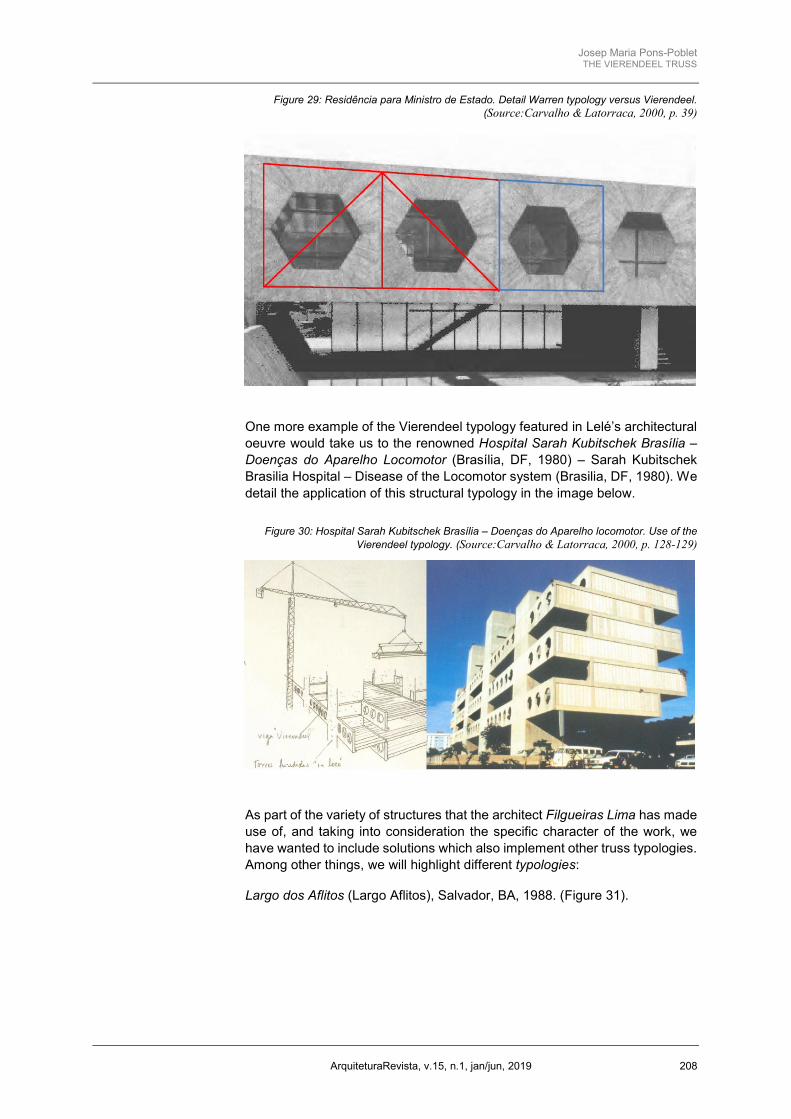
One more example of the Vierendeel typology featured in Lelé’s architectural oeuvre would take us to the renowned Hospital Sarah Kubitschek Brasília – Doenças do Aparelho Locomotor (Brasília, DF, 1980) – Sarah Kubitschek Brasilia Hospital – Disease of the Locomotor system (Brasilia, DF, 1980). We detail the application of this structural typology in the image below.
Figure 30: Hospital Sarah Kubitschek Brasília – Doenças do Aparelho locomotor. Use of the Vierendeel typology. (Source:Carvalho & Latorraca, 2000, p. 128-129)
As part of the variety of structures that the architect Filgueiras Lima has made use of, and taking into consideration the specific character of the work, we have wanted to include solutions which also implement other truss typologies. Among other things, we will highlight different typologies:
Largo dos Aflitos (Largo Aflitos), Salvador, BA, 1988. (Figure 31).

Josep Maria Pons-Poblet THE VIERENDEEL TRUSS
ArquiteturaRevista, v.15, n.1, jan/jun, 2019 209
Figure 31: Largo dos Aflitos. (Source:Carvalho & Latorraca, 2000, p. 176)
The Sede do Tribunal de Contas da União no Estado da Bahia (Headquarters of the Federal Court of Accounts in the State of Bahia), Salvador, BA, 1995. (Figure 32).
Figure 32: Sede do Tribunal de Contas da União no Estado da Bahia. (Source:Carvalho & Latorraca, 2000, p. 218)
And the Centro de pesquisas agropecuárias do Cerrado (Cerrado Farming Research Center), Brasília, DF, 1978) (Figure 33).
Conclusions
Jules Arthur Vierendeel introduced a new structural typology characterized by being a framed truss, featuring high degrees of hyperstaticity, as well as upright members which are very firmly pinned to the chords. From its introduction by the Belgian engineer, the lack of diagonals caused a certain mistrust in the typology, which only slowly came to be overcome, becoming in the process a structural typology to be found nowadays in any treatise of this field.

Josep Maria Pons-Poblet THE VIERENDEEL TRUSS
ArquiteturaRevista, v.15, n.1, jan/jun, 2019 210
Structurally, this truss typology requires much more complex calculations due to the rigid conditions created by the existence of bending, shear, and axial forces.
But the said negative attributes can’t overshadow its aesthetic and physical benefits. The absence of diagonals allows for more space, increases the feeling of transparency and, furthermore, it makes it for people or other elements to pass through it, as opposed to other classical typologies, which make this practically impossible.
Figure 33: Centro de pesquisas agropecuárias do Cerrado. (Source:Carvalho & Latorraca, 2000, p. 95).
REFERENCES BENDIXEN, A. 1914. Die Methode der Alpha-Gleichungen zur Berechnung von Rahmenkonstruktionen. Berlín, 86 p. https://doi.org/10.1007/978-3-662-26154-5
CASTIGLIANO, A. 1879. Théorie de l'équilibre des systèmes élastiques et ses applications. Turín, 480 p.
CLAPEYRON, B. P. E. 1857. Calcul d’une poutre élastique reposant librement sur des appuis inégalement espacés. Comptes Rendus hebdomadaires des Séances de l'Académie des Sciences, 45: 1076-1080.
CROSS, H. 1930. Analysis of Continuous Frames by Distributing Fixed-End Moments. Proceeding of the American Society of Civil Engineers, 56: 919-28.
EATON, L. K. 2006. Hardy Cross American Engineer. Champaign, IL: University of Illinois Press, 136 p.
CARVALHO, M., LATORRACA, G. 2000. João Filgueiras Lima Lelé: Arquitetos Brasileiros = Brazilian Architects. Lisboa, Portugal: Editorial Blau; São Paulo, SP, Brasil: Instituto Lina Bo e P.M. Bardi, 263 p.

Josep Maria Pons-Poblet THE VIERENDEEL TRUSS
ArquiteturaRevista, v.15, n.1, jan/jun, 2019 211
HEYMAN, J. 1998. Structural Analysis: A Historical approach. Cambridge: Cambridge University Press, 220 p. https://doi.org/10.1017/CBO9780511529580
MOHR, O. C. 1874. Beitrag zur Theorie der Bogenfachwerkstränger. Zeitschrift des architekten und Ingenieur-Vereins zu Hannover, 20: 223.
VIERENDEEL, A. 1920. Cours de stabilité des constructions. Louvain: A. Uystpruyst, 191 p.
WILSON, MANEY. 1915. Bulletin 80 Univers. Illinois. Eng. Exp. Station.
FERRER, F. ALARCIA, J. 2014. Alarcia Ferrer Arquitectos: Pabellón-Puente. Disponível em: http://www.alarciaferrer.com.ar/index.php. Acesso em: 25/02/2019.
NOTES
i The Pratt truss owes its name to engineer Thomas W. Pratt (1812–1875) and his father Caleb Pratt. ii The Howe truss owes its name to architect William Howe (1803–1852). iii The Warren truss owes its name to engineer James Warren (1806–1908). iv Joao da Gama Filgueiras, or “Lelé” as he is best known, on top of being the great architect he is, encompassing art and technology as few can, is an admirable person (Marcelo Carvalho Ferraz). v The use of these beams made the existence of large spans of the first level possible, thereby providing a better integration between the pool, living, and game environments, etc. Also, the construction gained lightness and above all a character of greater dignity required by the program.
Submetido: 02/03/2018 Aceito: 25/06/2018