
THE VIBRATION AND BALANCING OF AN UNBALANCED …
12
66 THE VIBRATION AND BALANCING OF AN UNBALANCED FLEXIBLE ROTOR By R. E. D. Bishop* and G. M. L. Gladwellt The motion of a flexible unbalanced rotating shaft is examined. The effects of balancing such a shaft (as a ‘rigid body’) in a conventional low-speed balancing machine are explained. The underlying theory of a general method of balancing flexible rotors, mode by mode, is then given. The paper contains a discussion of the effects of dead weight on the deflection of a rotating shaft. INTRODUCTION A SHAFT may be said to be ‘out of balance’ if its mass axis does not coincide with its elastic axis. Lack of balance produces the phenomenon of whirling and this paper is concerned with the way in which it does so. The first satisfactory treatment of this problem was given by Jeffcott (1)). In his well-known paper on the subject, he first describes the salient features of shafl whirling in qualitative terms and then states that : ‘It is proposed. . . to discuss to some extent how want of balance causes these (whirling) phenomena, and to what extent in good practice balancing should be carried. It should be pointed out, however, that an adequate mathematical treatment of the general case of a loaded shaft is a matter of considerable diffculty, and that the discussion . . . does not pretend to be more than illustra- tive.’ The nature of his investigation is best described in his ‘For the sake of simplicity in illustrating the character of these vibrations we will consider the case of a light uniform shaft supported freely in bearings at its ends and carrying a mass m at the centre of its span, the mass centre, however, being slightly eccentric by a distance a from the elastic centre of the shaft.’ Now Jeffcott’s analysis, while it clearly deals with a very highly idealized system, has the great merit of simplicity. Accordingly, it is reproduced in several textbooks on vibration and, as a consequence, has become very familiar. The MS. of this paper was received at the Institution on 11th March 1959. * Kennedy Professor of Mechanical Engineering in the University of London (University College). Associate ‘Member of the ITlStitUtiOTl. t Assistant Lecturer in Mathematics, University College, London. $ A numerical list of references is given in Appendix II Journal Mechanical Engineering Scimce own words : It was intended to give a simple mathematical picture of whirling phenomena and this it does admirably. But the theory is not suitable for the quantitative analysis of real rotors, for which it was never intended. A less drastic idealization is desirable for the purpose and an attempt is made to satisfy this need in this paper. The problem of a rotating, massive, uniform shaft with an initial lack of straightness is related to that of an un- balanced shaft. The former has been treated by Johnson (2) and the treatment of the latter (which is given here) was suggested by his work. Now Johnson’s discussion of initial lack of straightness was amplified in a previous paper (Bishop (3)) and it will be convenient at several points, here, to draw on the results found previously. It may be mentioned that the processes which are described in this article are also applicable to shafts of non-uniform section. The theoretical justification for this is a little more complicated and will be given in a later article devoted to non-uniform shafts in general. Notation The notation is, in general, that used in Bishop (3). The following are the more important additional symbols which are employed in this report; symbols which are defined and only used locally in the text are not listed here. a, a’ g ml,m2 . . . n Components of eccentricity of mass axis in directions OU, OV (being functions of x only). = a+ia’ See equations (92). = a,+ia,‘ rth coefficientof a series representing unity (see equation (78)). Acceleration due to gravity. Balancing masses. Balancing masslunit length. Vol I No I I959
Transcript of THE VIBRATION AND BALANCING OF AN UNBALANCED …

66
THE VIBRATION AND BALANCING OF AN UNBALANCED FLEXIBLE ROTOR
By R. E. D. Bishop* and G. M. L. Gladwellt The motion of a flexible unbalanced rotating shaft is examined. The effects of balancing such a shaft (as a ‘rigid body’) in a conventional low-speed balancing machine are explained. The underlying theory of a general method of balancing flexible rotors, mode by mode, is then given. The paper contains a discussion of the effects of dead weight on the deflection of a rotating shaft.
INTRODUCTION A SHAFT may be said to be ‘out of balance’ if its mass axis does not coincide with its elastic axis. Lack of balance produces the phenomenon of whirling and this paper is concerned with the way in which it does so.
The first satisfactory treatment of this problem was given by Jeffcott (1)). In his well-known paper on the subject, he first describes the salient features of shafl whirling in qualitative terms and then states that :
‘It is proposed. . . to discuss to some extent how want of balance causes these (whirling) phenomena, and to what extent in good practice balancing should be carried. It should be pointed out, however, that an adequate mathematical treatment of the general case of a loaded shaft is a matter of considerable diffculty, and that the discussion . . . does not pretend to be more than illustra- tive.’ The nature of his investigation is best described in his
‘For the sake of simplicity in illustrating the character of these vibrations we will consider the case of a light uniform shaft supported freely in bearings at its ends and carrying a mass m at the centre of its span, the mass centre, however, being slightly eccentric by a distance a from the elastic centre of the shaft.’ Now Jeffcott’s analysis, while it clearly deals with a very
highly idealized system, has the great merit of simplicity. Accordingly, it is reproduced in several textbooks on vibration and, as a consequence, has become very familiar.
The MS. of this paper was received at the Institution on 11th March 1959.
* Kennedy Professor of Mechanical Engineering in the University of London (University College). Associate ‘Member of the ITlStitUtiOTl.
t Assistant Lecturer in Mathematics, University College, London. $ A numerical list of references is given in Appendix I I
Journal Mechanical Engineering Scimce
own words :
It was intended to give a simple mathematical picture of whirling phenomena and this it does admirably. But the theory is not suitable for the quantitative analysis of real rotors, for which it was never intended. A less drastic idealization is desirable for the purpose and an attempt is made to satisfy this need in this paper.
The problem of a rotating, massive, uniform shaft with an initial lack of straightness is related to that of an un- balanced shaft. The former has been treated by Johnson (2) and the treatment of the latter (which is given here) was suggested by his work. Now Johnson’s discussion of initial lack of straightness was amplified in a previous paper (Bishop (3)) and it will be convenient at several points, here, to draw on the results found previously.
It may be mentioned that the processes which are described in this article are also applicable to shafts of non-uniform section. The theoretical justification for this is a little more complicated and will be given in a later article devoted to non-uniform shafts in general.
Notation The notation is, in general, that used in Bishop (3). The following are the more important additional symbols which are employed in this report; symbols which are defined and only used locally in the text are not listed here. a, a’
g ml, m2 . . . n
Components of eccentricity of mass axis in directions OU, OV (being functions of x only).
= a+ia’ See equations (92). = a,+ia,‘ rth coefficient of a series representing
unity (see equation (78)). Acceleration due to gravity. Balancing masses. Balancing masslunit length.
Vol I No I I959

THE VIBRATION AND BALANCING OF AN UNBALANCED FLEXIBLE ROTOR 67
XI, x2 . . .
ff) a’
Radius of shaft. Co-ordinates defining the points of
attachment of masses ml, m 2 . . . (see Fig. 3) with respect to the rotating axes O W .
Co-ordinates of centre of mass (being functions of x and t ) defining its position with respect to the fixed axes OYZ.
Values of x defining the transverse planes in which masses ml, m 2 . . . are attached.
Components of eccentricity of mass axis in directions OU, OV after balancing masses are attached (functions of x only).
= cc+ia’ See equations (40). = ar+ia,‘ Angle by which the deflection due to
forced motion in the rth pair of modes lags behind the correspond- ing components of eccentricity.
ASSUMPTIONS AND EQUATIONS OF MOTION
Consider a shaft of uniform circular cross-section. If this shaft is bent slightly, its geometric axis is neither extended nor compressed since it is common to all neutral planes of flexure. This conclusion is reached without reference to the way in which the mass of the shaft is distributed through it, but it is concerned with the Young’s modulus (which is supposed uniform throughout the material). It will be convenient to refer to this axis, which is neither extended nor contracted, as the ‘elastic axis’.
Let the shaft have constant mass Ap per unit length, but suppose that the mass centres of the thin discs, into which the shaft may be imagined cut, lie on a line which does not coincide exactly with the elastic axis. This might be regarded as the result of slight lack of uniformity of density in the material and its effect is to make the shaft unbalanced.
Following the notation of Bishop (3), the axes OXYZ in Fig. 1 are fixed in space with OX coinciding with the undeflected elastic axis of the shaft. The axes O X W rotate with the angular velocity Q of the shaft. Thus a line which is imagined drawn parallel to OU on some cross- section of the shaft will remain parallel to that axis although the section may move about (in translation only) relative to the rotating plane UOV. We now consider the motion of the thin slice of the shaft which is distant x along the axis OX from 0 and whose thickness is 6x (Fig. 1).
The co-ordinates of the intersection E of the elastic axis with the plane faces of the slice are v, Y’ and these quantities are time-dependent. The centre of mass C of the slice has the coordinates v+u, v’+a’, where a and a‘ do not vary with time, being functions only of x. Journal Mechanical Engineering Science
Fig. 1. Slice of Shaft Shoeving Positive Directions of Shearing Force and Bending Moment
Consider the motion of the slice in the direction OU under the influence of the components Sly S2 of shearing force. The equation of motion is
S,-S2 = Ap . ~x[W-(V+U)G-~ .L%’] (1) so that, in the limit as Sx + 0,
* (2) -- as - Ap[w-(v+a)Q2-2.L%’] ax
The relation between the bending moment and shearing force is found by taking moments about an axis parallel to ov; this gives
M ~ - M ~ + S S X = 0 * * (3) provided that the rotatory inertia of the element about a diametral axis is neglected. This result becomes, in the limit
. . * * (4) aM S = -- ax
The bending moment is related to the curvature of the shaft by the relation
We may now substitute back into equation (2) to eliminate S and so reach the equation
EI a4v a+ --- = W-(V+U)Q’-~.Q~’ . (6)
The equation for motion pardel to OV may be found in a like manner and it is, in fact
--- = W’-(v’+a‘)$22+rn+ . (7) A~ a+
An allowance both for internal and external damping may be incorporated in this theory and there is no necessity to show here how this may be done, because the appropriate terms have been found by Bishop (3) and they may be used directly in equations (6) and (7). It will be seen by reference
Vol I No 1 1959

68 R. E. D. BISHOP AND G. M. L. GLADWELL
to equations (70) and (71) of Bishop (3) that the equations of motion become
EZa4v bi be AptW Ap Ap
&(v+a)Q2-2&j' = ----- w-- ( tx2v ' )
i EZa4v' bi be $-(v'+a')Q2+2Q6 = -- --- v --($+Qv) ~ ~ a x 4 A~ A,,
. . - (8) where bi and be are the coefficients of internal and external damping respectively. It is worth remarking here that the external damping force has been taken as being propor- tional to the velocity of E and not the mass centre C; if it were related to C the last term in the first of equations (8) would contain the factor i-Q(v'+a') instead of (6-Qv').
Let 7 = v+iv'; ti = a+ia' . . (9)
so that equations (8) become
. . . (10)
[ = u + i ~ ' = 7 & ~ . . - (11)
When referred to the fixed axes OYZ, the position of the elastic axis is given by the co-ordinate t, where
Substituting the expression .fe-iQr for 7 in equation (10) gives the relation
This form of the equation of motion is often the one whose solution is the more useful since the components u, u' of 6 are readily measured by means of stationary pick-ups.
Solution of the Equations of Motion The equations governing 5 and r ] having been found, they may be solved by the method used in (3)-that is, by seeking a solution in the form of a series of the characteristic functions r$l(~), r$2(~), . . . of the shaft.
It is first necessary to express the eccentricity d in series form. Let
t i ( X ) = C E & ) . . * (13) r= 1
where the complex constants cir produce a real series (representing a(x)) and an imaginary series (representing ia'(~)). Turning to equation (lo), we now consider a solution of the form
W
7(x, t> = 2 vr(t) * - * (14) r = l
where the complex coeffidents r ] , yield a real series for .(x, t) and an imaginary series for iv'(x, t). These series for (r and 7 may now be substituted in equation (10). If th is is done and the result (used in (3))
is used, together with the notation bi = 2~,w,.Ap; be = 2prwrAp . . (16)
then it is found that
+r+ 2[(/++vr)wr+ al.ir + (w? - Q2+ 2iprwrQ) vr = Q*Zr . . . (17)
where w, is the rth natural frequency of free flexural vibration in the absence of damping. As was the case previously (3), the co-ordinates 7, remain independent when damping is included in the theory, indicating that the modal shapes for damped free vibration are the same as the principal modes.
The solution of equation (17) consists of a particular integral and a complementary function. The latter portion is the general solution of the equation when the term on the right-hand side is replaced by zero so that it represents the 'free motion' of the shafi. The nature of th is free motion need not be discussed here since it has been dis- cussed previously (in (3)); it is sufficient, for present purposes, to remember that the free motion will be unstable if
Q tLr+vr ->- '"r "r
So far as the limited problem that Jefkott took up is con- cerned, the introduction of an allowance for internal damping (and hence the possibility of instability) can be discussed by adapting the work of Fujii (4).
Consider now the forced motion; a particular integral of equation (17) is
. . . . (18)
. . . (19) where
This result may now be interpreted in terms of the deflec- tions in the principal modes of the shaft, since the rth pair of principal co-ordinates are p , and p,' where
7r=Pr+ipr' - - - (21) When 52 < wry 7, and 5, are both small. The elastic axis
thus suf€ers only slight distortion in the rth pair of modes; what distortion there is in these modes occurs in a plane that almost coincides with that containing the rth com- ponent dr of the eccentricity a(~ ) . The arrangement at any section is as shown in Fig. 2a in which the axes and shaft are supposed to rotate about 0 while remaining stationary with respect to each other. This state of affairs persists, with bigger and bigger deflections, if Q/w, is taken larger, until this ratio approaches the value unity.
AS Q/wr + 1,
$nmnal Mechanical Engineering Science
9%
Vol I No I 1959

THE VIBRATION AND BALANCING OF AN UNBALANCED FLEXIBLE ROTOR 69
so that the configuration is as shown in Fig. 2b. The distortion of the elastic axis is large and it occurs almost entirely in the rth pair of principal modes; it lags behind the rth component of d by 7r/2 radians. This condition of the shafi exists at the rth whirling speed.
a W C b
Fig. 2. Defection in rth Mode Relative to Rotating Axes O W During Forced Motion
a Below resonance. b At resonance. c Above resonance.
axis in the rth modes tends to the value If f2 is much greater than wr, the distortion of the elastic
yr = fire-,, . . . - (23) This indicates that the mass axis (rather than the elastic axis) comes into near-coincidence with the line of bearings; the configuration is as shown in Fig. 2c.
The phenomenon of whirling may thus be described in the following terms. As the angular velocity f2 of the shaft is slowly increased, whirling will take place in the first, second, . . . modes as f2 passes through the values wl, w2, . . . In the vicinity of the whirling condition the distortion of the shaft will be large and it may be regarded as being confined almost entirely to one of the pairs of modes. The distortion in these modes will then be in quadrature with the corresponding components of the unbalance. This r6gime breaks down, however, if the condition of instability is reached (in accordance with equation (18)); in this event the shaft will execute an outward spiral motion in its first pair of principal modes with angular velocity wl, of the type described in (3).
The foregoing observations relate to the solution of equation (10). Equation (12) may be solved in a similar way. Consider the trial solution
rn
The complex coefficients 5, produce a real series and an imaginary one, the former representing u(x, t ) and the latter iu’(x, t). If this series is substituted in equation (12) it yields
~ r + 2 ( ~ , + ~ r ) ~ r ~ r + ( ~ y 2 - 2 i ~ r ~ ~ ) t r = S22dr@ (25) and the solution is again composed of a complementary function (representing free motion) and a particular integral (giving the forced motion). The nature of that part of the solution relating to the free motion is described in (3). On the other hand the forced motion is again given by equation (19), when the extra multiplying factor e‘Jat is added. Journal Mechanical Etlgineering Science
ALTERNATIVE FORMS OF THE ANALYSIS In the above analysis, we have chosen to fix the position of the elastic axis by the co-ordinate y so that the position of the mass axis is defined by y+d. The reason for doing this is that the elastic axis is assumed to be coincident with the geometric axis, the motion of which might be detected with pick-ups; the variation of 7 can be measured by pick- ups which rotate with the shaft. But there is no funda- mental reason why the. elastic axis should coincide with the geometric axis and another, alternative set of assumptions is that the mass axis should do so. In this case we could use y to define the (measurable) deflection of the mass axis and let 7-6 give the position of the elastic axis. If this latter scheme is adopted and the theory is again traced through, it is found that equations (10) and (12) are again reached with the difference that the factor wr2 appears on the right- hand side in place of Q2 in each case. While this change of viewpoint is of little practical significance, it has an interesting effect on the side of theory; for it makes the present problem (of an unbalanced shaft) mathematically identical with that of an initial bent shaft (3).
The effect of this change is to remove the symbol a from equation (2), leaving it otherwise unaltered. Equation (4) is unchanged while equation (5) becomes
Thus equations (6) and (7) become
and the analysis now proceeds as before.
CONVENTIONAL ‘LOW-SPEED’ BALANCING The process of balancing a shaft involves the addition of small masses at the surface ih such a way as to cancel out the effects of the eccentricity 6(x). Ideally, this should mean that, by means of a judiciously selected distribution of mass, the mass axis is brought into coincidence with the elastic axis. Since this is both impossible and unnecessary, the alternative scheme could be adopted of balancing for the first, second, third . . . modes in turn until there is no necessity to go any further. This possibility is referred to in the next section.
At low speeds of rotation (such that $2 < wl) the rotor behaves as a rigid body; that is, its distortion is negligible. Even so, it may be necessary to improve the balance so as to diminish the forces which must be sustained by the rotor bearings. The process of balancing a rigid rotor is discussed by Den Hartog (5) and we need not discuss the technique here in detail.
The process of ‘rigid body’ or ‘low-speed’ balancing has two objects. The first of these is to ensure that the centre of mass of the rotor lies on the centre line of the bearings so that no net force must be applied to the shaft due to
Vol I No I 1959

70 R. E. D. BISHOP AND G. M. L GLADWELL
centrifugal action*. Expressed analytically, this means that it is ensured that
Jo Apa(x) . Q2dx = 0 =I, Apa'(x) . S22d.x (28)
any corrections being made by the addition of smal l masses ml and m2 whose position on the surface at the balancing planes x = x1 and x = x2 are (rl, r i ) and (r2, r i ) respec- tively (Fig. 3). Thus, if equation (28) is not satisfied for a given shaft, the relations
are made to hold as a result of 'static balancing'.
V
Fig. 3. Notation Used When a Balancing Mass ml is Attached to Shaft at Section x = x1
The second purpose of low-speed balancing is to ensure that the rotating shafl does not transmit to its bearin@ a rotating couple (whose axis is perpendicular to the axis of the shaft) due to centrifugal acti0n.j- This would be the state of affairs, with a rigid rotor, if
I 1.' Apa(x) .B2xdx = 0 = Apa'(x)@xdx (30)
In general, of course, this condition is not satisfied by an unbalanced shaft so that, by the process of 'dynamic balancing', the relations
\ (31) , : ~ ( x ) . ~22xdx+m~r~a2x~+m~r2a2x2 = o f ~ p a ' ( x ) . ~ 2 2 x d ~ + m ~ r l l a 2 x ~ + m ~ r 2 ) ~ 2 2 x ~ = o
are satisfied. In the absence of balancing masses, the contributions
made by the lack of balance to the 'unbalance' in the rth mode are given by
I
1 = 7 a(x> * 1
1 - a: =zJ
where
2 =I' [+,(X)]2dx . . . (33) 0
* Since the shaft is presumed rigid, gravity effects may simply be su$erimposed so that an upward force equal to its weight must be supplied at the bearings. t It should be noted that the adjective VyMmic', when applied to balancing, is not always used in this sense (cf. Grobel (6)); here it wall be used in this way however.
. ' h m l Mechanical Engineering Science
If balancing masses are added, e.g. in conformity with equations .(29) and (31), these expressions for a, and a,' are modified and the way in which they are changed will now be examined.
Let the position of the mass axis (after the balancing masses have been added) be given by
so that the symbol a replaces a. We shall here suppose that masses are added at two planes x1 and x2 only, the method of extending the theory to more planes being obvious. The function G(x) is everywhere the same as Z(x) except over any segment where there is a balancing mass. If a balancing mass is added over an interval of length 6x about the section x = x1 then for x1-8x/2 Q x < x1+6x/2 we have
- 01 ( x ) = Cr(x)+ia'(x) . . - (34)
} (35) Ap+) = Apa(x)+nlt.l Apa'(x) = Apa'(x)+nlrlr
where nl represents the applied masslunit axial length (nl < Ap). That is
a(x) = a@)+- . . (36)
01'(x) = a'@) + - AP 1
*I X 1
Fig. 4. Modification of the Projecth of the M a s Axis on the Plane OUX Produced by Attaching Balancing Masses ml andm2 at x = x1 a n d x = x2
The addition to a(x) which gives a(x) is therefore of the form shown in Fig. 4 (where the offset at x = x2 is also shown). This addition may be expressed in the form of a series in the functions +,(x), the coefficient of the rth term being
If we now let h16x = ml and n26x = m2 and let Sx tend to zero while ml and m2 remain finite we find that this coefficient reduces to
Thus
m I
r = l . . . (39) Vol I No I 1959
THE VIBRATION AND BALANCING OF AN UNBALANCED FLEXIBLE ROTOR 71
where the coeflicients a,, a,.’ of the original series are given by equations (32).
If, during the process of low-speed balancing a mass is added at a node of deflection in the rth principal mode, then equation (39) shows that the amplitude of whirling at the rth critical speed will not be altered thereby. In general, however, the tendency to whirl at any given critical speed will be modified, either for the better or the worse.
The significance of the functions a(x) and a’(x) can be seen by reference to equation (19). These quantities are given in series form in equation (39), being of the form
W W
r= 1 r= 1
The complex quantities
replace the quantities E, in equation (19) since they repre- sent the new unbalances in the modes after the addition of balancing masses.
The remainder of this section is devoted to a discussion of the effects on the ‘modal unbalance’ (i.e. on the com- ponents of eccentricity) of conventional low-speed balancing. It is first noted that, as a result of static balancing
- a, = a,+ia,‘ . . . . (41)
s,’ Apa(x) . sZ2dx = 0 = Apa‘(x) . Q2dx (42) s,’
loZ while the dynamic balancing gives
f Apa(x) . Q2xd.x = 0 = Apa‘(x) . Q~XCLX (43)
These results are obtained by replacing a(x) and a’(%) by a(.) and a’(#) in equations (28) and (30). These restrictions on the final unbalance Z(x) are only of an ‘averaging’ nature and the problem is now to examine what individual com- ponents E, may remain after balancing. In other words, the question of what lack of balance will satis6 equations (42) and (43) is now examined.
When the series (40) are substituted into equations (42) and the constants Ap and Q2 are cancelled out, it is found that, after static balancing,
W m
where A, = +,(x)dx . . . (45)
The analogous result, corresponding to dynamic balancing, may be found from equation (43); it is
2 Bra, = 0 = 2 Bra,’ . . r=l r = l
(46)
where B, = f x+,(x)dx . . * (47)
Integration by parts of this expression yields the result
B, = 1 Joz +r(x)h-J:{jox +rWdx}h (4)
3@ Mechanical Engineering Science
or
where B,= IAr-C, . . . * (49)
To s u m up, then, low-speed balancing ensures that m m
TA,Zr = 0 = 2 C;, . . (51) 4 r = l r=l
These results may be expressed in a particularly simple form in the case of a pinned-pinned shaft. The charac- teristic function +,(x) is sin(r~x/Z) so that A , and C, are easily evaluated. They are, in fact,
(r even) f0 . . (52) I A,= 21
(r odd) t 12 c, = - -m
The results (51) now reduce to
The static balancing accounts for the odd modes and the dynamic balancing for the even ones in this particular case*.
The important thing to notice i s that, not only is there the possibility of residual ‘modal unbalances’ GI(#) after low-speed balancing, but the contribution in any particular pair of modes may be increased. Whether or not this is so depends on whether or not the expression (38) increases a, and a similar expression increases a:.
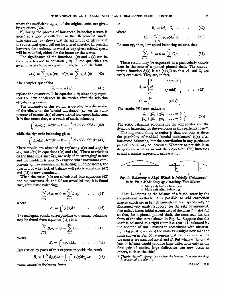
U b Fig. 5. Balancing a Shaft Which is Initially Unbalanced
in its First Mode Only by Attaching Two Masses a Mass axis before balancing. b Mass axis after balancing.
That, in improving the balance of o ‘rigid’ rotor by the conventional methods, it is possible to add correction masses which are in fact detrimental at high speeds may be illustrated very easily. Suppose, for the sake of argument, that a shaft has an initial eccentricity of the form d = E,+,(x) so that, for a pinned-pinned shaft, the mass axis has the form of the sine curve shown in Fig. 5a. Suppose that the shaft is balanced as a rigid rotor (i.e. that it is balanced by the addition of small masses in accordance with observa- tions taken at low speed) the mass axis might now take the form shown in Fig. 5b, assuming that the regions at which the masses are attached are A and B. But whereas the initial lack of balance would produce large deflections only in the first pair of modes, large deflections can now occur in others, such as the third. * Clearly this will always be so when the bearings in which the shaft
is supported are identical. Vol 1 No 1 1959

72 R. E. D. BISHOP AND G. M. L. GLADWELL
THE BALANCING OF FLEXIBLE ROTORS In the last section the effects on a flexible rotor of low-speed balancing were discussed. Now it has been recognized for years that low-speed balancing is inadequate for flexible shafts that must run through critical speeds and alternative techniques have been proposed (for example, see Grobel(6) and Den Hartog (5)). Rather than enter into a detailed discussion of these procedures here, the general theory of how balancing should be carried out will now be taken up.
It is seen from equation (19) that, as the speed s1 of a shaft increases towards the value wl, the distortion in the first mode becomes large. The elastic axis moves away from the line of bearings, as we have seen, and the bowing is such that the ‘heavy side’ is outward. This is illustrated in Fig. 6 where the axis OU has been affixed to the shaft so as to coincide with the plane of the initial eccentricity in the first pair of modes. The dotted line shows the path of E and a few positions of E and C (each corresponding to a Werent value of s1) are shown by the lines EIC1, E2C2 . . . which always remain parallel to the axis OU. For each of these positions, an arc has been described with E as the centre and a small cross is placed on each arc at the furthest point from 0; this is the point which would be marked by a stationary scriber, brought up to touch the shaft. Fig. 6 shows that, as the shaft speed sd approaches the
value w1 the stationary scriber will mark the shaft on rhe trailing side of the plane containing the eccentricity. It has been suggested by Jeffcott (1) that, by reversing the direc- tion of rotation and hence marking the shaft on the other side of the plane, it should be possible to determine the position of that plane. This, however, can only be satis- factory if the two marks obtained in this way are close together, sipce the speed range corresponding to most of
”\
Fig. 6. Positions of the LineJoining the Intersection E of the Elastic Axis with a Cross-section and the Intersection C of the First Component of Unbalance with that Cross- section fm Various Speeds
Journal Mechanical Engineering Science
the dotted locus E1E7 in Fig. 6 is relatively smaU and it is difficult to maintain a steady speed near whirling.
A more practical method of locating the plane of the eccentricity dl+l(x) is to run the shaft dowe the critical speed so that it is marked on the ‘light side’. The mark will then lead the required plane slightly and reversal of the direction of rotation will give a second mark from which the plane of the eccentricity may be found. A difKculty in this is that some higher mode than the first may become dominant if $2 exceeds w1 to the extent of approaching wZ; but this can be met by marking the shaft at a node of the second pair of principal modes so that it is the remoteness of L? from w3 which remains to be thought of*.
When the plane of the eccentricity til+l(x) has been determined, a distribution of balancing masses should be added on the light side of the shaft. The purpose of this is to diminish the quantity dl as far as possible without increasing the quantities d2, t i 3 . . . The nature of this requirement may be seen by reference to Fig. 7 in which
@ n. 6~
Fig. 7. Attachment of Mass n Per Unit Run to Counteract
EC is the component of eccentricity corresponding to the first pair of modes, whose plane is supposed to have been found. In order to bring C into coincidence with E, mass n per unit run must be added to the s h p on the light side; thus for a length Sx of the shaft
so that
the Ec~enh.icity si1+1(~)
n . 6%. r = Ap .ax. dl+l(x) . . (54)
APdl n = -+&) . . . (55) r where r is the radius of the shaft. In general dl will not be known so that the intendy of the correction will have to be found by trial and error; but its dependence on x is through the fhction +l(x).
The second component of eccentricity may now be balanced out in the same way as the first. And so the process should go on until the shaft is sufficiently well balanced for the purpose that it has .to serve. This is doubtless more easily said than done. In general it is not possible to distribute the balancing
mass along the shaft, and instead it must be added in discrete portions. Suppose that this is the case. The plane of the eccentricity dl+l(x) in the first mode may be found as before and balancing masses may be attached so as to eliminate this component. This could be done in several ways, the simplest being merely to use a single balancing * When rotors are balanced at high speed, the use of a scriber in
these ways is quite impracticable; however, a simple electrical method can be used.
Vol 1 No I 1959

THE VIBRATION AND BALANCING OF AN UNBALANCED FLEXIBLE ROTOR 73
(that is, transverse-) plane, at x = xl, say; if the axis OU lies in the plane of the eccentricity (so that al’ is zero) then it is only necessary that
as will be seen from equation (39). The value ml of the added mass must be found by trial and error. It will be seen that, for a given unbalance al, the least value of ml that will be required is that corresponding to the maximum value of +l(x); thus the balance mass should be placed at the ‘loop’ of the first mode (as intuition would suggest) if it is to be as effective as possible. A suitable arrangement is shown in Fig. 8a for a pinned-pinned shaft; since +1(x) is always positive for this system, it follows that a positive value of al requires a negative mass ml. That is, the balance weight must be attached on the back of the shaft as indicated.
X X
a b
Fig. 8. Balancing a Shaft Mo&-@-Mode a Mass mi balancing the first component of eccentricity (a1 being
b Masses m2 and m3 balancing the second component of eccen-
The mass ml will affect the components of unbalance in the second, third . . . modes unless it lies at an appropriate node of deflection. Thus if the rotor in question is not intended to run much above its first critical speed, it may be sufficient to add the balancing mass at the node in the second mode (so that 62+2(x) retains its original magnitude) and to rely on the remoteness of w3, w4, . . . fiom subsequent running speeds to limit the deflections.
Having eliminated the first-mode component of the eccentricity, it may be necessary to eliminate the second; this will be the original component Z2+2(x) plus whatever was added when the first component was got rid of. The first thing is to find the plane in which the second com- ponent of unbalance lies and the method is similar to that described previously. Let this be the plane XOU so that a; = 0.
Now it is not usually possible to balance the second mode using only one balancing plane without destroying the balance in the first. This may be seen by inspection of equation (39) since to do so would require there to be a node of deflection in the first mode. It is possible, however, to proceed, using two balancing planes; let these be at x = x2 and x3 and let the corresponding balancing masses be m2 and m3. In order that the balance in the first mode shall not be impaired it is necessary that
while, for balance in the second mode,
much exaggerated).
tricity (a2 being much exaggerated).
m2+1(x2)+m3+l(x3) = 0 - - (57)
Journal Mechanical Engineering Science
The sections x2 and x3 may be chosen almost at random; it is necessary only that
Once these planes are chosen, the ratio m2/m3 is fixed by equation (57). For most types of end-fixings, this ratio will be negative so that m2 and m3 are of opposite sign (since deflections in the first mode all have the same sign). This means that m2 and m3 are on opposite sides of the axis in the plane XOU. The balance masses are now most effective if they are used at the points of maximum deflection in the second mode (where +2(x) has maximum values). A suitable arrangement is shown in Fig. 8b for balancing the second mode of a pinned-pinned shaft. Having balanced the first two components of eccentricity,
we may now wish to neutralize the third so that the plane of this component must be found. This can be done by running the shaft at or near its third ctitical speed and, when this plane has been found, balancing may be achieved by attaching balancing masses at the surface in that plane. It is at once clear that more than one mass must be used since a single attachment must cause unbalance in either the first or second modes.
If two balancing planes (with x = x4 and x = xs) are to be sufficient then it is necessary that
m4dl(x4)+mS#l(xS> = m4d2(x4)+mS$2(xS) = 0
It is clear that the two balancing planes cannot be chosen at random since we should then have three equations governing the values m4 and mS of the two masses. In fact it is possible to solve equations (60) only if
With this provision, it might be possible to use two-mass balancing ofthe third mode for certain types of shaft end- fixing. It is not likely to be easy, however, and is not possible for a pinned-pinned shaft, in particular. For in this case equation (61) becomes
so that either
or
The solutions of these equations are x4= 0 or 1 and xs = 0 or 1, or alternatively, x4 = x5. Thedore the masses must either be added at the ends or both be added in the same transverse plane. In the latter case, equation (60)
Vol I No I 1959

74 R. E. D. BISHOP AND G. M. L. GLADWELL
shows that the total mass added, m4+m5, is zero. None of these distributions have any effect on the third, or any other, mode.
It would be far more reasonable to attempt to use three masses m4, m5, and m6 at x4, x5, and x6 respectively. It is then necessary that
m441(x4) +m54 1(x5) + m6$1(x6) =
m442(x4)+ m542(x5> +m642(x6) =
Now x4, x5J and x6 can be chosen almost at random so that the coeflicients of m4, m5, and m6 are determined. And in general the equations can be solved for the masses, it being
As already mentioned, the three points may be chosen at random, subject to equation (66). The ratios of the masses to be added are then known, and their absolute magnitudes may be found by trial and error; for the magnitude of u3 will not be known.
In theory, the procedure for the fourth and higher com- ponents of the eccentricity is quite straight-forward. For the rth mode, we should have first to find the appropriate plane of the unbalance i,+,(x); it would then be necessary to add balancing masses in r transverse planes such that they satisfy r equations. Of the latter equations, r- 1 ensure that no new unbalance is introduced into the lowest r-1 modes. By this method only r balancing planes are needed in order to be able to balance the first r modes. It is only necessary that there are two, x2 and x3 for equations (57) and (58), three x4, x5, and x,5 for equation (65). The points x4, x5 may be the same as x2, x3, etc.
MODIFICATION OF THE BALANCING PROBLEM DUE TO INITIAL LACK OF
STRAIGHTNESS IN THE SHAFT So far, the whirling and balancing of a thin rotor have been considered in relation to the forcing motion generated by the cenn&gal force arising from the separation of the elastic and mass axes of the rotor. It has been shown (Johnson (2) and Bishop (3)) that initial lack of straightness Journal Mechanical Engineering Science
in the rotor will also produce a forced whirling motion. The lack of straightness reduces the elastic restoring force against any displacement and it is t h i s reduction in the elastic force which creates the forced motion. In any prac- tical case, both of these effects will be present and we shall now explain how this affects the foregoing analysis.
The rotor will be given a forced motion by the resultant of the two forces whose origins have been described. An analytical expression for this forced motion may be obtained by combining equation (19) with equation (80) of Bishop (3). It is
Balancing therefore becomes a process of adding masses until ir+Z, = 0, which state of affairs is achieved when the maximum amplitude of the vibration in the rth mode is annulled.
If the notation 2
b, = ir+@) Zr . . . (70)
is used, then q,, representing the forced motion in the rth mode, may be written
The plane of this displacement will vary from being in phase to being exactly out of phase with zr as Sa varies fiom very much less to well above w,; this phase change is identical with that described previously since 5, is the same. But now 6, is not constant and also varies in both magnitude and direction with SZ; for this reason the variation of 7, with speed is not the same as it would be in the absence of initial bend.
The balancing procedure outlined theoretically in the present report is st i l l applicable however if the relevant' equations are modified by replacing ir by i r + Z , (r = 1,2,3, . . .). After balancing in the manner which has been described, ip will have been altered such that 5, = -Zr, and the forced motion of the rotor in its rth mode will then be given by
This forced motion will always be small (that is, of order 2r) because, near a critical speed the numerator is small, while the denominator is large at other speeds.
Vol 1 No 1 1959

THE VIBRATION AND BALANCING OF AN UNBALANCED FLEXIBLE ROTOR 75
THE EFFECT OF THE WEIGHT OF THE SHAFT
When a shafi rotates with its axis horizontal, it sags slightly under its own weight. This effect will now be examined. The equations of motion of the shaft may be set up with allowance for this effect either by modifying the equations governing v and v’ or those governing u and u‘. The former case will be considered here.
The w&ght of the thin slice of the shaft (shown in Fig. 1) is Apg.8~ and it acts parallel to the fixed axis ZO. Equation (1) must therefore contain the additional term -Apg.Gx.sin Qnt on the left-hand side. This change modifies equation (6) so that it reads
EI a4v -- - = ii-(v+u)Q*-rnW‘+g sin St (73) ax4
where allowance has been made for lack of balance, but not initial bend. Similarly equation (7) becomes
EI a4v’
ax4 -_-- - i;’-(v‘+u’)QZ+rnW+g cos SZt (74)
If the damping terms are now incorporated, as in equations (8), and these results are now combined in the usual way, then they give
= 0%-ige-i” . . . (75) By the use of equation (11) it is now possible to find the
equation for 1. This is, in fact, .- b,+bi . EI a41 b.Q <+- <+---i‘- 5 = Qz&@t-ig (76) ~ ~ a f i
It is the solution of this latter form of the equations of motion which is of most interest and it is this which we shall now discuss.
If the series (24) is substituted in equation (76) and equation (15) is used to simplify the result, then equation (76) becomes ~r+2(~r+vr)wr$r+ (wt2-2ivrw~)~,
* (77) - QZdreiQl-- ig - zl +,(x)h - -
The last term may be arrived at by the following reasoning. Let
00
1 = erq5r(x) . . . (78) +=I
where el, e2, e3 . . . are a suitably chosen set of coefficients. Adopting the usual method for evaluating the coefficients of such a series, we multiply throughout by +,(x) and then integrate over the range 0 Q x Q 1. Since
this gives
Journal Mechanical Engineering Science
It follows that the last term in equation (76) may be written in the form
m
r = l
from which the last term in equation (77) is obtained. The appearance of the constant term
-4 [‘+r(x)dx . J o
on the right-hand side of equation (77) means that the particular integral of equation (25) must be supplemented by a new term which is independent of d and of the free motion. That is to say, in the steady state the distortion due to the weight is both coexistent with the forced motion and unaffected by it.
That part of the particular integral of equation (77) which arises from the weight of the shaft is
- (83) 5, = . . - ige, ( ~ ~ 2 - 2iv,w$)
This may be written in the form
(84) The negative value of q i indicates that the shaft sags in the shape of its rth mode. But the amount of the sag in this modal shape depends both on the rotational speed 8 and on the internal damping, having the value
?+,(x) . . . . (85) W t
when the shaft is stationary; this latter result may be verified directly. As the speed is increased, the sag decreases; moreover, the sag is also smaller, the higher the internal damping. There is no sag in modes for which e, = 0 and, for a pinned-pinned shaft, these are the even modes.
The positive value of qr in equation (84) shows that the shaft swings sideways in the direction OY as the speed l2 is increased, provided that e, is not zero. Again, this sideways displacement is dependent on the internal damping and it might afford a method of measuring this quantity (for example, see Lazan and W u (7)). It is notoriously diflicult to separate internal and external damping for the purposes of measurement.
The expression for the sag in the rth mode may be written in the polar form
gere -i t a n - l ( i i i )
* + r b ) (86) tr+r(x) = w . I J [ 1 + 4 v q w.I
Both magnitude and direction of the ‘sag’ of the rotor in any given mode are then influenced by the speed of rotation.
Vol I No I 1959

76 R. E. D. BISHOP AND G. M. L. GLADWELL
An elementary explanation, of a semi-qualitative nature, is given for this by Timoshenko (8).
APPENDIX I
LAGRANGE’S METHOD
The kinetic energy of the unbalanced shaft is
DERIVATION OF T H E E Q U A T I O N S OF M O T I O N BY
T = )J Ap(Uc~+rjc’2)dx . . . (87) 0
where uc, uc’ are the co-ordinates of the centre of mass C of the slice measured as shown in Fig. 9. We may now refer the motion to the rotating axes OUVX (in which case uc, uc’ must be expressed in terms of v, u’) or to the stationary axes OXYZ (which would require use of the co-ordinates u, u3.
Fig. 9. Notation Used to Locate Centre of Mass C by Reference to Fixed Axes OYZ
TO derive the equations of motion in terms of the co-ordinates u and v’, we first note that
so that uc+iuc‘ = (v+E)eiQr . . . . (88)
} - (89) uc = (.+a) cos Qt -(.‘+a? sin nt u/ = (.+a) sin Qt+(w’+a? cos Qt
If these expressions are differentiated with respect to time, squared and added, they give
li,Z+#,‘Z = w 2 + ~ ’ 2 + ( w + a ) z Q 2 + ( w ’ + a ~ 2 Q z
-2Q[6(d+d)-6’(v+a)] . . . (90) Let
W m
and W m
a = 2 ar$r(x); 4’ = 2 at‘drQ - (92) r = l r = l
If these sezies are substituted into the expression (90) for iC,Z +&’z and the integration of equation (87) is performed, it is found that
m
2T = A p Z C ~~‘+~~2+(Pt+ar)’SZ’+(p,’+a,32Q2 r = l
-2n~r(pr’+ar?--A’(pr+rrrll} . . (93) The contributions from the kinetic energy terms of the Lagrangean equations are thus
The contributions of the dissipation function and of the potential energy may be found by the methods described in Appendix I of (3).
If, instead of the co-ordinates v and u‘, the Co-ordinates u and I(‘ are to be employed, then alternative substitutions must be made for Gc and ti/ in equation (87). Now
so that uc+iuc‘ = s+ZeiQt . . . . (95)
- * (96) u, = u+acosQt-a’sinQr
uc’ = u’+a sin Qf +a’ cos Qt } It is thus found that
i r C 2 + l i C ‘ Z = 2;2+k’2+SE2(a2+a”)-22Jaii(a sin Qt+a’cos Qt)
+2Qk’(acos‘Qr-a’sinQr) . . . . (97)
Let the displacements u, u’ be expressed in series form such that
W 00
u = 2 q&X); U’ = 2 qr’(x) . . (98) r = l r = l
If these series, together with those for a and a’ are introduced into equation (97) and the integration of equation (87) is per- formed, then it is found that
m
2T = ApZ C (4r’+~r’2+Qz(ar2+~’z) r = l
-2Q&(ar sin Qt+ar‘ cos Qt)
+2Q&’(~r cos Qt-ar’sin Qt)} . . (99)
The contributions of the kinetic energy to the Lagrangean equations are
The contributions of the dissipation function and of the potential energy may be found as in Appendix I1 of (3) and, when assembled, these various contributions yield equation (25) as they should.
Consider now the effect of the weight of the shaft. The potential energy is modified. This quantity is increased by the amount
V = Apguc‘& . . . . (101) !: where, by equations (96) and (98),
r = l
The appropriate contributions of the term (101) in the complete expression for V, to the Lagrangean equations, are
This is in agreement with the result found in the text.
APPENDIX I1
REFERENCES
(1) JEFFCOTT, H. H. 1919 Phil. Mag. (Series 6), vol. 37, p. 304, ‘The Lateral Vibration of Loaded Shafts in the Neigh- bourhood of a whirling Speed: The Effect of Want of - - Balance’.
Vibration of a Rotating Elastic Body’. (2) JOHNSON, D. C. 1952 Aircr. Engng, vol. 24, p. 234, ‘Free
Journal Mechaniial Engiieering Science Vol I No I 1959

THE VIBRATION AND BALANCING OF AN UNBALANCXD FLEXIBLE ROTOR 77
(3) BISHOP, R. E. D. 1959 J. mech. Engng Sci. vol 1, p. 50, ‘The Vibration of Rotating Shafts’.
(4) FUJII, S. 1951 Proc. 1st Japan Nut. Cong. appl. Mech., p. 599, ‘The Poles of Resistances in the Vibration of a Rotating Shaft’.
(5) DEN HARTOG, J. P. 1956 ‘Mechanical Vibrations’, fourth edition, chapter 6 (McGraw-Hill Book Co., New York and London).
Journal Mechanical Engineering Science
(6) GROBEL, L. P.
(7) LAZIUJ, B. J. and Wu, T.
1953 Gm. Elec. Rev., vol. 56, No. 4, p. 22, ‘Balancd’ Turbine-Generator Rotors’.
1951 Proc. Amer. SOC. Test. Muter., vol. 51, p. 649, ‘Damping, Fatigue and Dynamic Stress- Strain Properties of Mild Steel’.
(8) TMOSHENKO, S. P. 1955 ‘Vibration Problems in Engineer- ing’, third edition, p. 230 (Van Nostrand, New York and London).
Vol I No I I959